Building Design Services in a Distributed Service...
50
Building Design Services in a Distributed Service Architecture Charles S. Han 1 , John C. Kunz 2 , Kincho H. Law 3 Center for Integrated Facility Engineering Stanford University Stanford, CA 94305-4020 Abstract This paper describes a distributed service architecture that enables the delivery of building design services over the Internet. The architecture of an individual service is three-tiered. The first tier is a common communication protocol interface. The middle tier is the common product model interface. The third tier is the core of the design service. With the standardization of the first two tiers, it is possible to rapidly deploy various design services, both new and legacy applications, that can be easily accessed via the Internet. As examples of building design services, the prototype implements a project manager service with a companion CAD package, a disabled building code analysis service, and a service that generates and displays an accessible path for a wheelchair for a given building design using motion planning and animation techniques. Key Words automation, distributed object environment, Common Object Request Broker Architecture (CORBA), World-Wide Web (WWW), Computer-Aided Design (CAD), disabled access, robotics, motion planning, animation, Virtual Reality Modeling Language (VRML), product model, Industry Foundation Classes (IFC) 1 Graduate Student, Department of Civil and Environmental Engineering, Stanford University, Stanford, CA 94305, [email protected] 2 Senior Research Associate, Center for Integrated Facility Engineering, Stanford University, Stanford, CA 94305, [email protected] 3 Professor, Department of Civil and Environmental Engineering, Stanford University, Stanford, CA 94305, [email protected] 1
Transcript of Building Design Services in a Distributed Service...
Building Design Services in a Distributed Service Architecture
Charles S. Han1, John C. Kunz2, Kincho H. Law3
Center for Integrated Facility Engineering Stanford University Stanford, CA 94305-4020
Abstract
This paper describes a distributed service architecture that enables the delivery of
building design services over the Internet. The architecture of an individual service is
three-tiered. The first tier is a common communication protocol interface. The middle
tier is the common product model interface. The third tier is the core of the design
service. With the standardization of the first two tiers, it is possible to rapidly deploy
various design services, both new and legacy applications, that can be easily accessed via
the Internet. As examples of building design services, the prototype implements a project
manager service with a companion CAD package, a disabled building code analysis
service, and a service that generates and displays an accessible path for a wheelchair for a
given building design using motion planning and animation techniques.
Key Words
automation, distributed object environment, Common Object Request Broker
Architecture (CORBA), World-Wide Web (WWW), Computer-Aided Design (CAD),
disabled access, robotics, motion planning, animation, Virtual Reality Modeling
Language (VRML), product model, Industry Foundation Classes (IFC)
1 Graduate Student, Department of Civil and Environmental Engineering, Stanford University, Stanford, CA 94305, [email protected] 2 Senior Research Associate, Center for Integrated Facility Engineering, Stanford University, Stanford, CA 94305, [email protected] 3 Professor, Department of Civil and Environmental Engineering, Stanford University, Stanford, CA 94305, [email protected]
1
Introduction
Traditional CAD systems are monolithic in that all functions or “services” are bundled in
a software package. With the maturation of information and communication
technologies, the concept that distributed CAD services are delivered over the Internet,
Internet-based Computer-Aided Design (I-CAD), is becoming a reality. Regli (1997)
outlined the technologies that are now readily available to make the network-enabled
CAD environment possible. Specifically, the technologies include:
1. A standard product model.
2. A distributed object environment that allows for the development and transfer of a
design based on the standard product model.
This paper describes a prototype implemented to illustrate a framework that provides
building design services over the Internet.
The benefits of the framework for distributed design services are at least twofold. First,
the framework provides a means to distribute design services in a modular and systematic
way. With this infrastructure, users have the ability to select appropriate design services
(as opposed to having to use a large monolithic design tool) and can easily replace a
service if a superior service becomes available without having to recompile the existing
services being used. Second, it provides a means to seamlessly integrate a legacy
application as one of the modular design services in the infrastructure. With the
standardization of the communication protocol and the exchange of product model data,
integration of legacy applications as well as deployment of new design packages
becomes a straightforward task.
In the prototype implementation, a project manager service with a companion CAD
package and two design applications with companion viewers have been developed to
demonstrate the operation of the infrastructure. The project manager service acts as a
building design (model) repository as well as a portal to direct a client application to
other services provided in the infrastructure. A companion CAD package, a client
2

application of the project manager service, has access to the building design repository of
the project manager service and queries the project manager service for the location of
other appropriate services available over the Internet. The first design application is the
integration of a service that performs compliance checking of a design against a building
code for disabled accessibility (Han et al.1998). The second design application is a
service that generates and displays a wheelchair accessible route for a given floor plan
design.
The distributed object environment layer of the services is implemented with the
Common Object Request Broker Architecture (CORBA) (Vogel and Duddy 1997), and
the International Alliance for Interoperability (IAI) Industry Foundation Class (IFC)
product model is used for the common product model layer (Industry 1997). For the
CAD service implementation as well as views of the data generated by the design
services, standard World-Wide Web (WWW) browser technologies are employed
although the use of these technologies is not mandatory for the functionality of a service
or a view of a service within the infrastructure. However, using a standard browser
interface leverages the most widely available Internet environment as well as being a
convenient means of quick prototyping.
Infrastructure Framework
Figure 1 shows the conceptual network-enabled framework for a distributed service with
three application services and a broker. In this framework, each individual service
adheres to a three-tiered architecture. The first tier, a communication protocol interface,
gives the application services a common means to send and receive design data over the
Internet. The middle tier, the common product model interface, is a standard protocol
that describes the design data. The third tier is the core of the design service—the design
service extracts the appropriate information of the building design through the common
product model interface and either modifies the design data or generates a report based
on the analysis of the data. As shown in Figure 1, the broker does not need the product
model interface that is present in the services. An application package will register with
3

the broker to advertise its services in the infrastructure. Another service will query the
broker for the existence of services in the distributed service architecture. The
registration and query service is based on a predetermined constraint language, but the
broker does not have to be aware of the underlying product model that is being used to
exchange design data between services. In the following, the design of the three-tiered
architecture is examined in detail.
The Communication Protocol Interface
Methods that define the communication protocol interface that are made publicly
available by the broker and the services are illustrated in Figure 2. Following the object-
oriented paradigm, the “exposed” methods are the points of entry into the broker and the
services, but the actual implementation of these methods is dependent on the individual
broker or service. The following discussion describes the minimum requirements for the
communication protocol.
In the simple prototype implementation, the broker interface defines only two methods,
register() and query(). When an application registers its services with the
broker, it provides two arguments, the service that is being registered and a string that
describes the service. When the broker is queried for a service, the broker returns a
registered service that matches the description of the query argument. In a real
implementation of this infrastructure, a more sophisticated broker protocol would be
necessary. For example the client would need to provide client registration information
and, for building code analysis services, geographic location and a more specific
description of the type of building code (structural, mechanical, electrical, etc). An even
more sophisticated protocol would involve a more extensive communication sequence
between a client and the broker. For example, the client could query the broker for a set
of existing services that match a specific set of constraints, and then the client could
choose among the services returned by the broker. For the purposes of the prototype, this
simple interface is sufficient to illustrate the minimum specification of the broker. For
further description on a broker protocol, see the discussion on the CORBA Trading
Service by Vogel and Duddy (1997).
4

The service interface for communication is also very simple with put() and get()
being the most important methods. The put() method sends the product model to the
service with two arguments, a string identifying the name of the model and a stream of
data that defines the model. The get() method returns a model with the name
identified by the single string argument.
Services themselves have the ability to process a query concerning the existence of other
services through a project manager service module. The motivation for providing this
ability is that in an enterprise environment, the user of a CAD package may not be given
the responsibility of knowing what services should be used. The project manager service
has the responsibility of filtering the information given by the broker.
Finally, when a service is initiated, it can be queried for its status with the status()
method since a service may not necessarily process the information or complete the work
immediately. With this small set of methods for the broker and a service, the
communication protocol layer is fully functional and can be utilized by an application
that operates within the distributed network-based environment.
The Product Model Interface
In order to create an infrastructure in which design services can be incrementally added
and since each service will have its own representation of the design data, the availability
of multiple services suggests a mapping of each service’s design data representation to a
common model. Without this lingua franca, a process that needs to use a specific service
would need to have a mapping of its representation of the design data to the service’s
design data representation, and the need to use a new service would require additional
mapping.
With the three-tiered service architecture illustrated in Figure 1, the product model
interface has been deliberately decoupled from the communication protocol interface.
Using a distributed object paradigm, it would have been possible to expose the objects or
building components of a common product model in the communication protocol
5

interface, thus combining the communication protocol and product model layers.
However, if the objects (and their attributes and relationships) are made public at the
communication protocol level, as the product model evolves, the communication protocol
must also evolve to take into account the product model evolution. By decoupling the
two layers, it is up to the individual service whether the product model interface needs to
be modified to accommodate the product model evolution.
As previously noted, the put() and get() methods of the communications protocol
interface take as input and output a stream of design data as strings. In decoupling the
two layers and keeping the infrastructure general, the trade-off comes in the efficiency of
sending the design data. The integrated approach of defining the objects at the
communication protocol layer would be much more efficient but requires the continuing
evolution of the communication protocol as the product model evolves. Although there
are no restrictions on how the string array is imposed by the infrastructure itself, in the
prototype, the string array is a description of the model in EXPRESS format to conform
with the standard IFC product model (Industry 1997).
The product model interface stores the design data according to the individual service’s
needs. In the implementation of the prototype, all application services (as well as the
client CAD package) store the design data in a hash table keyed by the building
component identification string. The critical constraint is that each individual service is
able to understand the common product model that has been agreed upon a priori.
However, by making the product model storage consistent across the infrastructure, it
would be easier to reuse methods to extract and to send the critical data from the product
model to the core of the design service for the appropriate analysis.
The Core of the Design Service
Any application service needs to extract a view or a diagram from the product model
(Clancy 1985). The transformation from the product model to a view or a diagram is
unique to the application. The core of the design service needs to map the common
product model data to its own design data representation. If part of the task of the design
6

service is to modify the product model that has been deposited into its repository, the
service must then perform a reverse mapping from its own design data representation
back to the common product model to update the model. Otherwise, the service simply
generates a report.
In the prototype, the two design applications simply generate a report after mapping the
common product model to their own design data representation and performing some
analysis. Therefore, each of these services represents a one-way exchange of design data.
To generate their respective reports, these services translate their own internal design
data representations into human-readable formats. If the services were to report their
findings directly to the originating process, a two-way exchange of design data would be
required. The project manager is an example of a service that performs both input and
output of a design model, a two-way exchange of design data. Even though the project
manager is only a repository and does not modify the design data, it still must perform a
mapping and a reverse mapping corresponding to the input and the output of a building
model.
The Distributed Service Architecture Prototype
This section describes the technologies used to implement the distributed service
architecture for building design services as illustrated in Figure 3. For the design
services, the communication protocol layer is implemented using CORBA, and the IAI
IFC (Industry 1997) is employed as the common product model. A seamless interface
between CORBA and the IAI IFC would be critical for the proliferation of
communication and services across the Internet for building design applications. The IAI
IFC product model effort is the only building product model that has the support of major
CAD vendors and manufacturers associated with the building industry.
CORBA provides a high-level distributed object paradigm that is well-suited to
implement a network-based distributed service architecture. Specific desirable features
include interface implementation independence, object access independent of the
7

implemented programming language, object access independent of location, and access
to standard distributed object services and facilities (Vogel and Duddy 1997).
Java is employed as the programming language to implement most parts of the
distributed service architecture, both the services as well as the service clients. Java’s
well-designed object-oriented structure and platform independence were the influencing
factors in using it as the implementing programming language. The wide proliferation of
the Internet can be attributed to the ease of World-Wide Web access, so taking advantage
of this environment was appropriate. When interaction was needed within the Web
browser environment, Java applets could be seamlessly integrated into the Java-written
distributed architecture. The client CAD package and the accessible path viewer employ
Java applets to create browser-based interfaces.
The disadvantage of Java’s implementation of platform independence is execution speed.
Thus, the motion planner and the animator are application service programs written in
C++ for optimal computational performance. Since Java provides simple methods for
incorporating external processes, the integration of the C++-written applications within
the Java-written infrastructure was straightforward.
The Common Distributed Object Environment
The communication protocol interface shown in Figure 2 is the Interface Definition
Language (IDL) file used to generate the CORBA-related Java source code. Using an
IDL-to-Java generator (provided by the Java Development Kit 1.2 from Sun
Microsystems), source code known as stubs and skeletons is generated for the broker and
the services. Note that a service is an application program that interacts with the broker
in the form of registration and queries, and the CAD client is the program that interacts
with the project manager service. Once the stubs and skeletons associated with the IDL
file are generated, the developer can simply implement the exposed methods following
the object-oriented paradigm. Though applications access objects and their methods
defined in the IDL file in a distributed object environment across the Internet, from the
8

application’s point of view, these objects and methods are treated as local entities. This
concept underlines the power of the CORBA paradigm.
One feature of CORBA is the Naming Service which allows distributed objects or
applications to register and locate other distributed objects or applications at a common
location by name (Vogel and Duddy 1997). The order in which the various distributed
applications are launched is critical: The Naming Service must be launched first. For the
prototype, a broker called “SimpleTrader” is the first process that registers with the
Naming Service since the design services will register with the broker. The design
services must be launched before their respective clients (the CAD package is a client to
the project manager service, and the path-viewing is a client to the path planning service).
It is the responsibility of the project manager service to query the broker for the
availability of design services. If a design service has not been launched (and therefore
has not registered with the broker), when the broker is queried by the project manager
service for that design service, the broker will simply inform the project manager service
that the requested design service is not available.
When a design service is initialized, it queries the Naming Service for the broker object.
The Naming Service returns the broker object to the design service, which can now
register with the broker. Similarly, when a client of a design service is initialized, it
queries the Naming Service for a specific design service object. For example, the client
CAD package queries the Naming Service for the project manager service by its name
“ProjectManager”. Once the Naming Service returns the service object to the client, the
client can interact with the service using the exposed methods that are described in the
IDL file.
The Common Building Product Model
The communication protocol interface specifies methods for sending and retrieving a
building model from a service without the interface having any knowledge about the
semantics of the building model. However, understanding the semantics of the building
model is the responsibility of the product model interface. There have been several
9

research efforts to develop object-oriented CAD systems and object-oriented building
models that contain the necessary geometric, functional, and behavioral relationships of
building components (de Waard 1992, Garrett et al. 1989, Ito et al. 1989). Currently,
there is an effort by the International Alliance of Interoperability (IAI), a consortium of
CAD vendors and other AEC industry partners, to develop standards for a three-
dimensional project model that enables interoperability between applications by different
software vendors (Industry 1997). The development of IFC-compliant CAD and analysis
packages to enable interoperability is the main goal of the IAI. The same motivation for
developing a standard building product model applies to the development of the
distributed service architecture. The IAI’s effort includes defining a set of objects called
Industry Foundation Classes (IFCs) that adhere to the object-oriented paradigm.
IAI defines two standard formats for IFCs for sharing project data: a standard EXPRESS
file format and a distributed object specification using IDL. The IFC (Release 1.5)
project model is used as the point of departure for the common product model interface.
However, the EXPRESS file format (in the form of a data stream as opposed to a static
file) was chosen over the IDL specification to decouple the communication protocol
interface and the common product model interface.
The IFC-compliant design data stream transfers from one application via the
communication protocol interface to the product model interface of another service. The
product model interface constructs an IFC-compliant internal representation of the design
data from the data stream. A Java class structure that mirrors the IFC EXPRESS
schema’s class hierarchy, attributes, and relationships has been constructed for the
internal representation (see Figure 4). The communication protocol interface or the
common product model interface does not specify how the design data is stored, but in
the prototype implementation, the data is stored in a hash table keyed by the
identification string of the building component. The only restriction mandated by the
common product model interface is that the core of the design service accesses the
building components in the repository by the name of the model and the name of the
building component. Once the building components are stored in the hash table, the core
10

of the design service can extract the necessary data from the table to perform a particular
analysis.
The Design Services
A variety of the design services implemented using the prototype infrastructure
demonstrate the flexibility of the distributed service architecture. The combination of the
project manager service and a client CAD package illustrates a new application
developed specifically for the distributed service architecture, while the two design
services are legacy applications to various degrees. As shown in Figure 3, the client
applications of the design services vary in their use of the communication protocol
interface and the product model interface.
The Project Manager Service with a Client CAD Package
The project manager is a very simple service to illustrate the functionality of the
communication protocol and product model interface. Since the main function of the
project manager service is to act as a repository of building models, the service core layer
does not perform any design data extraction and analysis from the building model that
resides in the product model interface. The only other function the project manager
service has is to process queries from the client CAD package by first passing the queries
to the broker and then transferring the service object that the broker has returned back to
the CAD package. In an enterprise environment, instead of simply acting as a pass-
through mechanism, the project manager service may act as a security agent that would
filter the CAD package’s service request depending on the constraints of the specific
project.
The client CAD package, a combination of a Java Applet and a Virtual Reality Modeling
Language (VRML) (“Information” 1997) interface, is launched when its Web page is
accessed (refer to Figure 5 for a detailed diagram of the CAD package architecture). The
CAD package has a three-tiered architecture that is very similar to the service
architecture illustrated in Figure 3, but the CORBA communication protocol interface is
the complement of the service communication protocol: it sends requests to the project
11

manager using the get() and put() exposed methods. The applet first retrieves the
project manager service object from the CORBA Naming Service. Since the CAD
package has its own local repository of building components, its product model interface
is identical to the service product model interface. The third tier of the client CAD
package includes the UI. The Java applet handles the textual UI, and the applet
communicates with the VRML graphical UI using the VRML External Authoring
Interface (EAI) (Marrin 1997). The various aforementioned Web browser-associated
technologies allowed rapid prototyping of the client CAD package. Any commercial
IFC-compliant CAD package that could incorporate the CORBA communication
protocol could also be used.
The CAD package can retrieve building models either from the project manager service
repository or from a static local model file, which is an IFC-compliant file in EXPRESS
file format. The retrieved model can be viewed, modified, and saved back to the project
manager repository. In addition, the CAD package queries the project manager for the
available design applications that have been registered, and it can send the model that is
currently being developed to the design application.
The Disabled Access Code Analysis Service
The disabled access code analysis service is an example of a legacy client/server
application (Han et al. 1998) that is wrapped by the service. Once wrapped, the legacy
application can be integrated into the distributed service architecture. The legacy
client/server application shown in Figure 6 has its own proprietary communication
protocol interface and a different product model interface, an earlier Release 1.0 version
of the IAI IFC. Therefore, the core of the Java’s application service is to map the
common product model to the legacy application’s product model. Once the design data
is mapped, the service launches the legacy application which then sends the stream of
design data to the server where the code compliance checker resides.
The legacy server application receives the design data, runs a code compliance analysis
on the building model, and generates a Web page with a VRML model of the design with
redlines. The redlines have hyperlinks to code comments, and the code comments have
12
hyperlinks to the actual building code document, in this case, the Americans with
Disabilities Act Accessibility Guidelines (1997). Note that since the report generated by
the legacy application is a Web page with only simple hyperlink interaction, as illustrated
in Figure 3 and Figure 6, the Web page report has no CORBA communication protocol
or IFC product model interface.
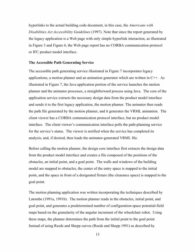
The Accessible Path Generating Service
The accessible path generating service illustrated in Figure 7 incorporates legacy
applications, a motion planner and an animation generator which are written in C++. As
illustrated in Figure 7, the Java application portion of the service launches the motion
planner and the animator processes, a straightforward process using Java. The core of the
application service extracts the necessary design data from the product model interface
and sends it to the first legacy application, the motion planner. The animator then reads
the path file generated by the motion planner, and it generates the VRML animation. The
client viewer has a CORBA communication protocol interface, but no product model
interface. The client viewer’s communication interface polls the path-planning service
for the service’s status. The viewer is notified when the service has completed its
analysis, and, if desired, then loads the animator-generated VRML file.
Before calling the motion planner, the design core interface first extracts the design data
from the product model interface and creates a file composed of the positions of the
obstacles, an initial point, and a goal point. The walls and windows of the building
model are mapped to obstacles, the center of the entry space is mapped to the initial
point, and the space in front of a designated fixture (the clearance space) is mapped to the
goal point.
The motion planning application was written incorporating the techniques described by
Latombe (1991a, 1991b). The motion planner reads in the obstacles, initial point, and
goal point, and generates a predetermined number of configuration-space potential-field
maps based on the granularity of the angular increment of the wheelchair robot. Using
these maps, the planner determines the path from the initial point to the goal point.
Instead of using Reeds and Shepp curves (Reeds and Shepp 1991) as described by
13

Latombe (1991a, 1991b) to create the non-holonomic path from a generated holonomic
path, the wheelchair robot is forced to go either forward or turn right or left at a
predefined radius. Thus, the path-planner creates a non-holonomic path from the
beginning. It uses a priority queue to prioritize the three choices in the event that the
wheelchair robot follows a local minimal path.
The motion planner creates a file with the sequence of positions of the wheelchair from
the initial point to the goal point. The animator reads in this two-dimensional
information to generate the motion of a wheelchair in VRML by calculating the major
and minor wheel movements and the arm motion of the wheelchair occupant.
Example Scenario
In this section, an example of how the distributed service architecture can be used is
presented. Referring to Figure 3, a broker process starts by registering itself with the
CORBA Naming Service. As noted earlier, the Naming Service is the mechanism that
allows other services to locate the broker. The two design services are initialized and
they locate and register with the broker. Finally, the project manager is initialized and
registers with the Naming Service so that the client CAD package can in turn locate the
project manager. Although the project manager does not register with the broker,
communications between the project manager and the broker are established in order to
access the services that do register with the broker, in this case the two design
applications.
When the client CAD package is brought up in a Web browser, the CAD package
establishes communications with the project manager. Once this communication is
established, the client CAD package can retrieve and save building designs to the project
manager. When the designer is interested in running a specific design service from the
client CAD environment, the client CAD package queries the project manager whether
that design service has been registered, and the project manager in turn queries the
broker. The broker returns the design service object to the client CAD package via the
14

project manager. At this point, the client CAD package sends the design data to the
design application and the design application can then proceed and perform the service
required.
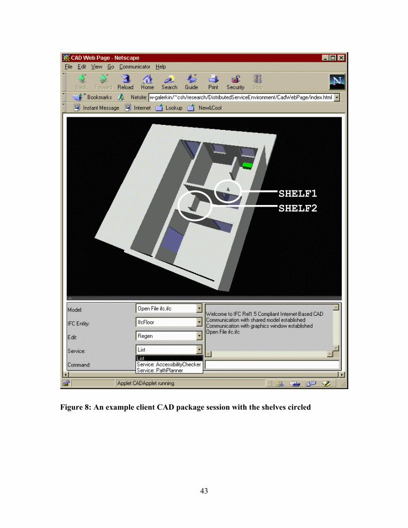
A designer can retrieve a model from the project manager service or from a local file as
illustrated in Figure 8 using the client CAD package. As shown in the figure, there are
two shelves included in the CAD model. The IFC-compliant model was created in an
IFC-enhanced AutoCAD environment (see Figure 9). AutoCAD blocks are mapped to
IFC building components; an AutoLisp program was written to extract this design data
and generate the IFC EXPRESS text file. When available, commercial IFC-compliant
CAD packages could be linked to the distributed service infrastructure as clients to the
project manager service by providing the communication protocol within the CAD
environment (Since no commercial IFC-compliant CAD packages were available when
the prototype was implemented, a simple browser-based IFC-compliant client CAD
package was developed in this study).
The designer executes the disabled access code-checking service to analyze the design
for local geometric code violations. The service generates the Web page shown in Figure
10 reporting that one of the doors, door001, does not comply with a building code
provision. Specifically, shelf1 intrudes upon a maneuvering clearance of door001.
When shelf1 is deleted and the disabled access code-checking service is run again,
door001 now complies with the regulations as shown in Figure 11.
To further explore the accessibility path from the entrance to the location of a building
component, the designer runs the wheelchair path-generating service. The generated path
shows the wheelchair having to go through an extra room in order to reach the designated
goal point, in this case a sink, because shelf2 blocks the middle hallway. Figure 12
illustrates the path generated by the motion planner, and Figure 13 illustrates the motion
planning results presented in the client viewer’s Web page. When the designer removes
the shelf from the design and runs the wheelchair path-generating service again, the
service generates the path illustrated in Figure 14 showing that the wheelchair can now
15

reach the room with the sink by going through the middle hallway. Figure 15 shows a
snapshot of the generated animation.
Discussion
This paper has described a distributed service architecture that allows design services to
be incorporated into a modular network-enabled infrastructure. Three such services, a
project manager and two design applications, were implemented. By providing a
modular infrastructure, services can be added or updated without re-compilation or re-
initialization of existing services. While this work has focused on automated disabled
access building design analysis, other building-design-related services can be
implemented and linked to the network infrastructure. For example, if a building
component inventory service is implemented, a designer could query such a service for
the availability and pricing of a specific component such as a fixture, an appliance, etc.
The infrastructure is contingent on two common interfaces, the communication protocol
interface and the common product model interface. As demonstrated, standardizing a
communication protocol and decoupling it from the product model interface has its
advantages and drawbacks. The major advantage is that the communication protocol
interface does not depend on changes (updates and evolution) of the product model since
the stream of design data is object-independent; it is the responsibility of the product
model protocol to parse the design data stream. The major disadvantage is the
inefficiency of the transmission of the design data from service to service.
Standardization of the product model is more of a challenge. While the services
demonstrated have simple mappings from the common product model to their own design
representations without loss of critical information, other services may need more
information than is provided in the standard product model, thus bringing up issues such
as object overloading. There are at least two issues that need to be addressed. First, the
product model must have a formal mechanism to extend the model with new attributes
and relationships. Second, in order to address the object overloading issue, there must be
16

a formal mechanism for a service to query the process that calls the service to extract
only the necessary attributes and relationships of a building design model.
Finally, the distributed service architecture prototype described in this paper does not
address issues of security raised by Regli (1997) and others (for example, see Wiederhold
et al. (1997) and version control (Krishnamurthy 1996)). Security issues could be
addressed in the communication protocol interface and the project manager service while
version control could be incorporated in the common product model interface.
Acknowledgments
This research is partially sponsored by the Center for Integrated Facility Engineering at
Stanford University.
References
Americans with Disabilities Act accessibility guide. (1997). Access Board, U.S.
Architectural and Transportation Barriers Compliance Board, Washington, D.C.
Clancy, W. J. (1985). Heuristic classification in artificial intelligence, Elsevier
Publishers B.V., North-Holland.
de Waard, M. (1992). “Computer aided conformance checking: checking residential
building designs against building regulations with the aid of computers,” PhD thesis,
Technische Universiteit Delft, The Hague, The Netherlands.
Garrett, J.H., Basten, J., Breslin, J., and Andersen, T. (1989). “An object-oriented model
for building design and construction,” Proc., Struct.Congress, ASCE, Reston, Va., 332-
341.
Han, C.S., Kunz, J.C., and Law, K.H. (1998). “A client/server framework for on-line
building code checking,” J. Comp. in Civ. Engrg., ASCE, 12(4), 181-194.
17

Industry foundation classes release 1.5, specifications volumes 1-4. (1997). International
Alliance for Interoperability, Washington D.C.
“Information technology—computer graphics and image processing—the virtual reality
modeling language (VRML)—Part 1: Functional specification and UTF-8 encoding.”
(1997). ISO/IEC 14772-1:1997, International Standards Organization, Geneva,
Switzerland.
Ito, K., Ueno, Y., Levitt, R.E., and Darwiche, A. (1989). “Linking knowledge-based
systems to CAD design data with an object-oriented building product model,” Tech. Rep.
17, Ctr. for Integrated Fac. Engrg., Stanford University, Stanford, Calif.
Krishnamurthy, K. (1996). “A data management model for change control in
collaborative design environments,” PhD Thesis, Dept. of Civ. Engrg., Stanford
University, Stanford, Calif.
Latombe, J.C. (1991a). Robot motion planning, Kluwer Academic Publishers, Norwell,
Mass.
Latombe, J.C. (1991b). “A fast planner for a car-like indoor mobile robot,” Proc., Ninth
National Conference on Artificial Intelligence, Anaheim, Calif., 659-665.
Marrin, C. (1997). Proposal for a VRML 2.0 Informative Annex: External Authoring
Interface Reference, an unpublished draft of a proposal to the ISO.
Reeds, J.A., and Shepp, R.A. (1991). “Optimal Paths for a Car that Goes both Forward
and Backaward,” Pacific J. Math., 145(2), 367-393.
Regli, W.C. (1997). “Internet-Enabled Computer-Aided Design,” IEEE Internet
Computing, IEEE 1(1), 39-50.
Vogel, A., and Duddy, K. (1997). Java programming with CORBA, John Wiley and
Sons, Inc., New York, N.Y.
18

Wiederhold, G., Bilello, M., Sarathy, V., and Qian, X.L. (1996). "Protecting
Collaboration,” Proc., NISSC'96 National Information Systems Security Conference,
Baltimore Md., 561-569.
19

Broker CoreCommunication
Interface
Service Core
CommunicationInterface
Product ModelInterface
Internet
Service Core
CommunicationInterface
Product ModelInterface
Service Core
CommunicationInterface
Product ModelInterface
20

// --------------------------------------------------------------------// Name: DistributedServiceArchitecture.idl// Author: Chuck Han//// --------------------------------------------------------------------//
module DistributedServiceArchitecture{
typedef sequence<string> StringArray;
interface Service;
interface TradingService // the broker{
void register(in Service service, in string serviceType);Service query(in string serviceType);
};
interface Service // the service{
void put(in string whichModel, in StringArray stringArray);StringArray get(in string whichModel);StringArray list();void tradingService(in TradingService tradingService);Service query(in string serviceType);short status(in string session);
};};
21

CORBANaming Service
SERVICEPath Planner
CORBA
IFC
BROKER:Trading Service
CORBA
SERVICEAccessibility
CORBA
IFC
SERVICEProject Mgr
CORBA
IFC
CLIENTCAD UI
CORBA
IFC
Internet
CLIENTViewer
CLIENTViewer
CORBA
22

IfcRoot
IfcModelingAid
IfcRelationship
IfcObject
IfcLocalPlacement
IfcGeometricRepresentation
IfcRelationship1toN
IfcProductIfcSpatialElement
IfcElement
IfcRelVoidsElements
IfcRelFillsElements
IfcSpace
IfcOpeningElement
IfcBuildingElementIfcBoundingBox
IfcDirection
IfcPlacement
IfcPoint IfcCartesianPoint
IfcAxis2Placement2D
IfcAxis2Placement3D
IfcDoor
IfcFixtureIfcFloor
IfcRoofSlab
IfcWallIfcWindow
23

Repository,Filter
CORBA
IFCJavaApplication:
CAD core,UI
CORBA
IFC
Internet
Java Applet:
VRML World:
Project Manager Service Client CAD Package
24

Mapper,Launcher
CORBA
IFC
Internet
JavaApplication:
LegacyClient/ServerPair:
Access Checking Service Checker Results
abcClient
abcServer
25

Mapper,Launcher
CORBA
IFC
Internet
JavaApplication:
LegacyApplications:
MotionPlanner
Animator
Poller,UI
CORBA
Java Applet:
VRML World:
Path Planning Service Path Animation Viewer
26

SHELF2SHELF1
27

28

door001
29

door001
30

31

32

33

34

List of Figures
Figure 1: A conceptual diagram of the distributed service architecture
Figure 2: The communication protocol interface
Figure 3: A distributed service architecture implementation
Figure 4: The IFC hierarchy implemented for the common product model
Figure 5: The program manager service and the client CAD package
Figure 6: The accessibility analysis service and the generated report
Figure 7: The wheelchair path planning service and the animation viewer
Figure 8: An example client CAD package session with the shelves circled
Figure 9: The design generated in an IFC-enhanced AutoCAD environment
Figure 10: Accessibility Checker results with the non-compliant door circled
Figure 11: Accessibility Checker results of the revised design
Figure 12: The path generated by the motion planner after the first design revision
Figure 13: The animated view after the first design revision
Figure 14: The generated path after the second design revision
Figure 15: The animated view after the second design revision
35

Broker CoreCommunication
Interface
Service Core
CommunicationInterface
Product ModelInterface
Internet
Service Core
CommunicationInterface
Product ModelInterface
Service Core
CommunicationInterface
Product ModelInterface
Figure 1: A conceptual diagram of the distributed service architecture
36

// --------------------------------------------------------------------// Name: DistributedServiceArchitecture.idl// Author: Chuck Han//// --------------------------------------------------------------------//
module DistributedServiceArchitecture{
typedef sequence<string> StringArray;
interface Service;
interface TradingService // the broker{
void register(in Service service, in string serviceType);Service query(in string serviceType);
};
interface Service // the service{
void put(in string whichModel, in StringArray stringArray);StringArray get(in string whichModel);StringArray list();void tradingService(in TradingService tradingService);Service query(in string serviceType);short status(in string session);
};};
Figure 2: The communication protocol interface
37

CORBANaming Service
SERVICEPath Planner
CORBA
IFC
BROKER:Trading Service
CORBA
SERVICEAccessibility
CORBA
IFC
SERVICEProject Mgr
CORBA
IFC
CLIENTCAD UI
CORBA
IFC
Internet
CLIENTViewer
CLIENTViewer
CORBA
Figure 3: A distributed service architecture implementation
38

IfcRoot
IfcModelingAid
IfcRelationship
IfcObject
IfcLocalPlacement
IfcGeometricRepresentation
IfcRelationship1toN
IfcProductIfcSpatialElement
IfcElement
IfcRelVoidsElements
IfcRelFillsElements
IfcSpace
IfcOpeningElement
IfcBuildingElementIfcBoundingBox
IfcDirection
IfcPlacement
IfcPoint IfcCartesianPoint
IfcAxis2Placement2D
IfcAxis2Placement3D
IfcDoor
IfcFixtureIfcFloor
IfcRoofSlab
IfcWallIfcWindow
Figure 4: The IFC hierarchy implemented for the common product model
39

Repository,Filter
CORBA
IFCJavaApplication:
CAD core,UI
CORBA
IFC
Internet
Java Applet:
VRML World:
Project Manager Service Client CAD Package
Figure 5: The program manager service and the client CAD package
40

Mapper,Launcher
CORBA
IFC
Internet
JavaApplication:
LegacyClient/ServerPair:
Access Checking Service Checker Results
abcClient
abcServer
Figure 6: The accessibility analysis service and the generated report
41

Mapper,Launcher
CORBA
IFC
Internet
JavaApplication:
LegacyApplications:
MotionPlanner
Animator
Poller,UI
CORBA
Java Applet:
VRML World:
Path Planning Service Path Animation Viewer
Figure 7: The wheelchair path planning service and the animation viewer
42
SHELF2SHELF1
Figure 8: An example client CAD package session with the shelves circled
43
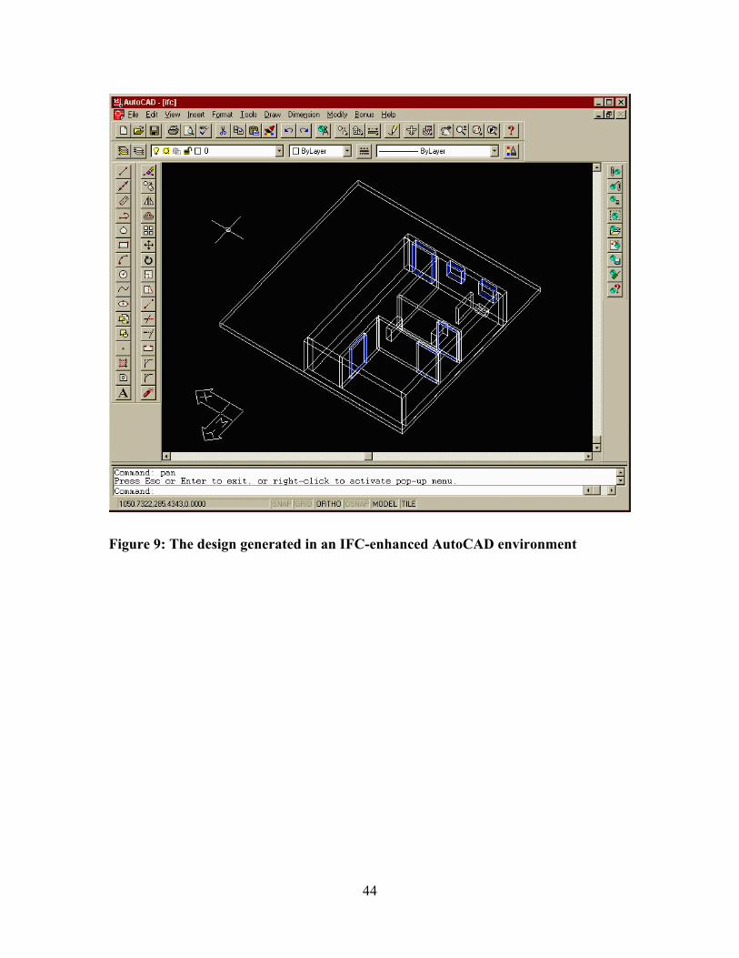
Figure 9: The design generated in an IFC-enhanced AutoCAD environment
44

door001
Figure 10: Accessibility Checker results with the non-compliant door circled
45

door001
Figure 11: Accessibility Checker results of the revised design
46
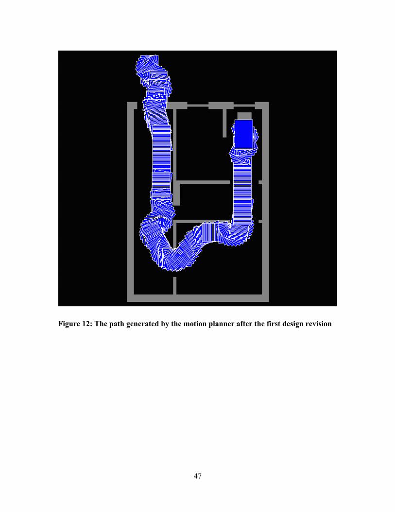
Figure 12: The path generated by the motion planner after the first design revision
47

Figure 13: The animated view after the first design revision
48

Figure 14: The generated path after the second design revision
49

Figure 15: The animated view after the second design revision
50