Building Code Handbook - Gila County, Arizona
41
GILA COUNTY RESIDENTIAL BUILDING CODE HANDBOOK Gila County Community Development 1400 E Ash St (mail only) 745 N Rose Mofford Way 608 E Highway 260 Globe, Arizona 85501 Payson, Arizona 85541 928-402-4224 928-474-9276 800-304-4452 Ext 4224 800-304-4452 Ext 7110 Fax: 928-425-0829 Fax: 928-474-0802 www.gilacountyaz.gov
Transcript of Building Code Handbook - Gila County, Arizona

GILA COUNTY
RESIDENTIAL
BUILDING CODE HANDBOOK
Gila County Community Development 1400 E Ash St (mail only) 745 N Rose Mofford Way 608 E Highway 260 Globe, Arizona 85501 Payson, Arizona 85541 928-402-4224 928-474-9276 800-304-4452 Ext 4224 800-304-4452 Ext 7110 Fax: 928-425-0829 Fax: 928-474-0802
www.gilacountyaz.gov

Building Code Handbook 2
Gila County Community Development March 30, 2011
The information contained in this Handbook is based primarily on the 2003 International Residential Code. It is intended to answer some of the most commonly asked questions regarding residential construction and to assist you in designing and building in compliance with the Building Code. If you do not find the information you need here, please check our website at www.gilacountyaz.gov or call our office in Payson at (928)474-9276 or our Globe office at (928)402-4224.
Building Code Handbook 3
Gila County Community Development March 30, 2011
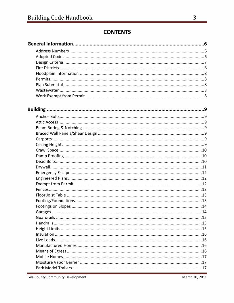
CONTENTS
General Information...............................................................................................6 Address Numbers ................................................................................................................. 6 Adopted Codes ..................................................................................................................... 6 Design Criteria ...................................................................................................................... 7 Fire Districts ......................................................................................................................... 8 Floodplain Information ........................................................................................................ 8 Permits................................................................................................................................. 8 Plan Submittal ...................................................................................................................... 8 Wastewater ......................................................................................................................... 8 Work Exempt from Permit ................................................................................................... 8
Building ..................................................................................................................9
Anchor Bolts ......................................................................................................................... 9 Attic Access .......................................................................................................................... 9 Beam Boring & Notching ...................................................................................................... 9 Braced Wall Panels/Shear Design ......................................................................................... 9 Carports ............................................................................................................................... 9 Ceiling Height ....................................................................................................................... 9 Crawl Space ........................................................................................................................ 10 Damp Proofing ................................................................................................................... 10 Dead Bolts .......................................................................................................................... 10 Drywall ............................................................................................................................... 11 Emergency Escape.............................................................................................................. 12 Engineered Plans ................................................................................................................ 12 Exempt from Permit ........................................................................................................... 12 Fences ................................................................................................................................ 13 Floor Joist Table ................................................................................................................. 13 Footing/Foundations .......................................................................................................... 13 Footings on Slopes ............................................................................................................. 14 Garages .............................................................................................................................. 14 Guardrails .......................................................................................................................... 15 Handrails ............................................................................................................................ 15 Height Limits ...................................................................................................................... 15 Insulation ........................................................................................................................... 16 Live Loads........................................................................................................................... 16 Manufactured Homes ........................................................................................................ 16 Means of Egress ................................................................................................................. 16 Mobile Homes .................................................................................................................... 17 Moisture Vapor Barrier ...................................................................................................... 17 Park Model Trailers ............................................................................................................ 17

Building Code Handbook 4
Gila County Community Development March 30, 2011
Retaining Walls .................................................................................................................. 17 Roof Rafter Tables .............................................................................................................. 18 Roof Load ........................................................................................................................... 19 Room Sizes ......................................................................................................................... 19 Skylights ....................................................................................................................................... 19 Snow Load .......................................................................................................................... 20 Soil Bearing Capacity .......................................................................................................... 20 Stairways ............................................................................................................................ 20 Swimming Pools, Spas & Hot Tubs ...................................................................................... 20 Termite Pre-Treatment ...................................................................................................... 24 Ventilation ......................................................................................................................... 24 Window Wells .................................................................................................................... 24 Wood-Protection Against Decay ......................................................................................... 25
Plumbing .............................................................................................................. 26
Backflow Prevention .......................................................................................................... 26 Clearances .......................................................................................................................... 26 Exempt from Permit ........................................................................................................... 26 Gas Piping Systems & Appliances ....................................................................................... 26 Installation ......................................................................................................................... 27 Testing of Systems.............................................................................................................. 27 Tracer Wires and Caution Tape .......................................................................................... 28 Valves ................................................................................................................................ 28 Vents .................................................................................................................................. 29 Waste Outlet Traps & Trap Arm Minimum Diameter .......................................................... 29 Waste Systems ................................................................................................................... 30 Water Conservation Standards ........................................................................................... 30 Water Heaters .................................................................................................................... 30 Water Pipe Sizing ............................................................................................................... 31 Water Supply ..................................................................................................................... 31
Mechanical ........................................................................................................... 33
Appliance Access ................................................................................................................ 33 Dryer Exhaust ..................................................................................................................... 33 Exempt from Permit ........................................................................................................... 33 Heat Source........................................................................................................................ 34

Building Code Handbook 5
Gila County Community Development March 30, 2011
Electric .................................................................................................................. 35 Bonding .............................................................................................................................. 35 Branch—Circuit Requirements .......................................................................................... 35 Conductor Types & Sizes .................................................................................................... 35 Electrical Equipment Location & Clearances ....................................................................... 36 Electrical Service Disconnect .............................................................................................. 37 Electrical Service Minimum ................................................................................................ 37 Exempt from Permit ........................................................................................................... 38 Receptacle Outlets ............................................................................................................. 38 Smoke Detectors ................................................................................................................ 39 Temporary Construction Power.......................................................................................... 39 Tracer Wires and Warning Ribbon ...................................................................................... 40 Trench ................................................................................................................................ 40 Wall Space ......................................................................................................................... 40

Building Code Handbook 6
Gila County Community Development March 30, 2011
GENERAL INFORMATION
ADDRESS NUMBERS:
Approved numbers or addresses must be plainly visible and legible from the street or road fronting the property. Addresses must conform to Gila County’s Rural Addressing System. For questions on Rural Addressing, call (800)304-4452, ext. 8510. (R321.1)
ADOPTED BUILDING CODES* EFFECTIVE MARCH 22, 2007
• 2003 International Building Code
• Arizonans with Disabilities Act (replaces Chapter 11 of the IBC)
• 2003 International Mechanical Code
• 2003 International Residential Code
• 2003 International Existing Building Code
• 2002 National Electrical Code
• 2000 Uniform Swimming Pool, Spa and Hot Tub Code
• 2006 International Plumbing Code
• 2006 International Fuel Gas Code
• The Latest Publication of Manufactured Home and Factory Built Buildings Installation Standards
*With amendments as listed in the Building Code Ordinance of Gila County

Building Code Handbook 7
Gila County Community Development March 30, 2011
CLIMATIC AND GEOGRAPHIC DESIGN CRITERIA: [TABLE R301.2(1)]
ROOF/GROUND SNOW LOADS * (psf)
below 2000 ft 2000 to 4500 ft 4500 to 6000 ft Above 6000 ft
= Roof 0 / Ground 0 = Roof 20/ Ground 25 = Roof 40/ Ground 50 = per historical data available
WIND SPEED
90 m.p.h. – 3 second gust wind velocity 75 m.p.h. – fastest mile wind speed
SEISMIC DESIGN CATEGORY**
B includes the following sites and vicinities: Pine, Strawberry, Payson, Control Rd., Christopher Creek, Rye, Gisela, Jakes Corner, Punkin Center, Tonto Basin, Young, Armer Ranch, Carrizo and Canyon Day
C includes the following sites and vicinities: Roosevelt Lake Dam, Roosevelt, Globe, Miami, Claypool, Hayden, Winkelman, Rose Creek Campground, Aztec Peak, Armer Mountain, Cutter, San Carlos, Sawmill and Seneca Lake
WINTER DESIGN TEMPERATURE
4500 ft and above below 4500 ft
= 15° = 24°
ICE SHIELD UNDERLAYMENT REQUIRED
NO
FLOOD HAZARDS
As determined by the Floodplain Department/Engineer
AIR FREEZING INDEX
Less than 1500 cumulative degree days below freezing County-wide
MEAN ANNUAL TEMPERATURE
61.8° average County-wide
SUBJECT TO DAMAGE FROM WEATHERING Moderate at 4600 feet and above
Negligible below 4600 feet FROST (footing depths)
Below 4900 feet Bottom of footing must be a min. of 12” below finish grade and a min. of 12” into undisturbed soil.
4900 feet and above
Bottom of footing must be a min. of 18” below finish grade and a min. of 12” into undisturbed soil.
TERMITES Moderate to Heavy DECAY None to Slight
* Roofs must be designed to support loads as specified in R301.6 or the snow load shown here, whichever is greater. (Ground Snow Load x .8 ≈ Roof Snow Load) ** See Seismic Design Category maps maintained by Community Development for locations not listed.

Building Code Handbook 8
Gila County Community Development March 30, 2011
FIRE DISTRICTS: Both Pine/Strawberry and Hellsgate are Fire Districts in Gila county with an adopted Fire Code. Any project within those districts that requires a building permit will require approval of the Fire District with jurisdiction.
Pine/Strawberry Fire Department 928-476-4272 Hellsgate Fire Department 928-474-3835
FLOODPLAIN STATUS REPORTS, CLEARANCES AND USE PERMITS: Contact: Carlos Ozuna at (928)402-8509 or 800-304-4452 x8509 (Globe area to Tonto Basin) Sine Scott at (928)474-7117 or 800-304-4452 x7117 (All remaining areas)
PERMITS REQUIRED:
Any owner or authorized agent who intends to construct, enlarge, alter, repair, move, demolish, or change the occupancy of a building or structure, or to erect, install, enlarge, alter, repair, remove, convert or replace any electrical, gas, mechanical or plumbing system, the installation of which is regulated by the 2003 IRC, or to cause any such work to be done, shall first make application to the building official and obtain the required permit. (R105.1)
PLAN SUBMITTAL REQUIREMENTS: See separate Gila County handout titled “Plan Submittal Checklist”
WASTEWATER: Contact Angela Parker at 928-474-9276 in Payson, or Jim Berry at 928-402-4223 in Globe
WORK EXEMPT FROM PERMIT: Per section R105.2 of the International Residential Code, certain work is exempt from permit requirements. See page 12 for Building Exemptions. See page 26 for Plumbing exemptions. See page 33 for Mechanical exemptions. See page 38 for Electrical exemptions. Exemption from the permit requirements of this code shall not be deemed to grant authorization for any work to be done in any manner in violation of the provisions of this code or any other laws or ordinances of this jurisdiction.

Building Code Handbook 9
Gila County Community Development March 30, 2011
BUILDING
ANCHOR BOLTS: Must be a minimum ½ inch in diameter spaced a maximum of 6 foot on center with 7 inches minimum embedment and be within 12 inches of corners, openings, or breaks in the plate or not less than 7 bolt diameters from each end of the plate. There must be 2 bolts minimum per section of plate. A nut and washer shall be tightened on each bolt to the plate. (R403.1.6 and Table R603.3.1)
ATTIC ACCESS: • Required in buildings with combustible ceilings or roof construction for attic areas
that exceed 30 square feet and have vertical height of 30 inches or greater. • Rough-framed openings shall not be less than 22 inches x 30 inches and shall be
located in hallways or other readily accessible location. • 30 inches minimum unobstructed headroom in the attic space shall be provided at
some point above access opening. • See Mechanical section for access requirements where mechanical equipment is
located in attics. • Switched light required if area is used for storage or contains equipment requiring
servicing. (R807.1, E3803.4)
BEAM BORING & NOTCHING: See R502.8.1 and R802.7.1 for sawn lumber restrictions. Not allowed in engineered beams
unless approved by the beam manufacturer or an engineer. (R502.8, R802.7)
BRACED WALL PANELS / LATERAL ANALYSIS / SHEAR DESIGN: See separate Gila County handout titled “Wall Bracing Handout”
CARPORTS: • Shall be open on at least two sides. • Floor surfaces shall be of approved noncombustible material. • The area of floor used for parking of automobiles or other vehicles shall be sloped to
facilitate the movement of liquids to a drain or toward the main vehicle entry doorway. (R309.4)
CEILING HEIGHT: • Habitable rooms, hallways, corridors, bathrooms, toilet rooms, laundry rooms and
basements shall have a ceiling height of not less than 7 feet.

Building Code Handbook 10
Gila County Community Development March 30, 2011
• Ceilings in basements without habitable spaces may project to within 6 feet, 8 inches of the finished floor; and beams, girders, ducts or other obstructions may project to within 6 feet, 4 inches of the finished floor.
• Bathrooms shall have a minimum ceiling height of 6 feet, 8 inches over the fixture. • A shower or tub equipped with a showerhead shall have a minimum ceiling height of
6 feet 8 inches at the showerhead. (R305.1)
CRAWL SPACE/UNDER FLOOR ACCESS: Access shall be provided to all under-floor spaces.
• Access openings through the floor shall be a minimum of 18 inches x 24 inches. • Openings through a perimeter wall shall be 16 inches x 24 inches. • Through wall access openings shall not be located under a door to the residence. • See Mechanical section for requirements where mechanical equipment is located
under floors. (R408.3)
DAMP PROOFING: • Foundation walls that retain earth and enclose habitable or usable spaces located
below grade shall be damp proofed from the top of the footing to the finished grade.
• French type drain system or equivalent may also be required to be installed. (R406.1)
DEAD BOLTS
All egress doors shall be readily openable from the inside without the use of a key or special knowledge or effort. (R311.4.4)
Building Code Handbook 11
Gila County Community Development March 30, 2011
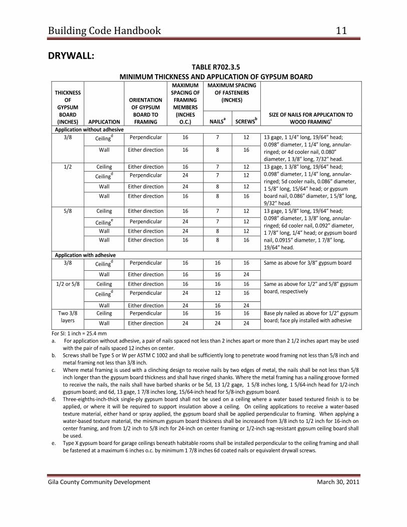
DRYWALL: TABLE R702.3.5
MINIMUM THICKNESS AND APPLICATION OF GYPSUM BOARD
THICKNESS OF
GYPSUM BOARD
(INCHES) APPLICATION
ORIENTATION OF GYPSUM BOARD TO FRAMING
MAXIMUM SPACING OF
FRAMING MEMBERS
(INCHES O.C.)
MAXIMUM SPACING OF FASTENERS
(INCHES)
SIZE OF NAILS FOR APPLICATION TO WOOD FRAMINGc NAILSa SCREWSb
Application without adhesive 3/8 Ceilingd Perpendicular 16 7 12 13 gage, 1 1/4” long, 19/64” head;
0.098” diameter, 1 1/4” long, annular-ringed; or 4d cooler nail, 0.080” diameter, 1 3/8” long, 7/32” head.
Wall Either direction 16 8 16
1/2 Ceiling Either direction 16 7 12 13 gage, 1 3/8” long, 19/64” head; 0.098” diameter, 1 1/4” long, annular-ringed; 5d cooler nails, 0.086” diameter, 1 5/8” long, 15/64” head; or gypsum board nail, 0.086” diameter, 1 5/8” long, 9/32” head.
Ceilingd Perpendicular 24 7 12
Wall Either direction 24 8 12
Wall Either direction 16 8 16
5/8 Ceiling Either direction 16 7 12 13 gage, 1 5/8” long, 19/64” head; 0.098” diameter, 1 3/8” long, annular-ringed; 6d cooler nail, 0.092” diameter, 1 7/8” long, 1/4” head; or gypsum board nail, 0.0915” diameter, 1 7/8” long, 19/64” head.
Ceilinge Perpendicular 24 7 12
Wall Either direction 24 8 12
Wall Either direction 16 8 16
Application with adhesive 3/8 Ceilingd Perpendicular 16 16 16 Same as above for 3/8” gypsum board
Wall Either direction 16 16 24
1/2 or 5/8 Ceiling Either direction 16 16 16 Same as above for 1/2” and 5/8” gypsum board, respectively Ceilingd Perpendicular 24 12 16
Wall Either direction 24 16 24 Two 3/8
layers Ceiling Perpendicular 16 16 16 Base ply nailed as above for 1/2” gypsum
board; face ply installed with adhesive Wall Either direction 24 24 24
For SI: 1 inch = 25.4 mm a. For application without adhesive, a pair of nails spaced not less than 2 inches apart or more than 2 1/2 inches apart may be used
with the pair of nails spaced 12 inches on center. b. Screws shall be Type S or W per ASTM C 1002 and shall be sufficiently long to penetrate wood framing not less than 5/8 inch and
metal framing not less than 3/8 inch. c. Where metal framing is used with a clinching design to receive nails by two edges of metal, the nails shall be not less than 5/8
inch longer than the gypsum board thickness and shall have ringed shanks. Where the metal framing has a nailing groove formed to receive the nails, the nails shall have barbed shanks or be 5d, 13 1/2 gage, 1 5/8 inches long, 1 5/64-inch head for 1/2-inch gypsum board; and 6d, 13 gage, 1 7/8 inches long, 15/64-inch head for 5/8-inch gypsum board.
d. Three-eighths-inch-thick single-ply gypsum board shall not be used on a ceiling where a water based textured finish is to be applied, or where it will be required to support insulation above a ceiling. On ceiling applications to receive a water-based texture material, either hand or spray applied, the gypsum board shall be applied perpendicular to framing. When applying a water-based texture material, the minimum gypsum board thickness shall be increased from 3/8 inch to 1/2 inch for 16-inch on center framing, and from 1/2 inch to 5/8 inch for 24-inch on center framing or 1/2-inch sag-resistant gypsum ceiling board shall be used.
e. Type X gypsum board for garage ceilings beneath habitable rooms shall be installed perpendicular to the ceiling framing and shall be fastened at a maximum 6 inches o.c. by minimum 1 7/8 inches 6d coated nails or equivalent drywall screws.

Building Code Handbook 12
Gila County Community Development March 30, 2011
EMERGENCY ESCAPE: Basements with habitable space and every sleeping room shall have at least one openable
emergency escape and rescue opening. Where basements contain one or more sleeping rooms, emergency egress and rescue opening shall be required in each sleeping room, but shall not be required in adjoining areas of the basement.
• Sill height of not more than 44 inches above the floor. • Minimum net clear opening height of 24 inches. • Minimum net clear opening width of 20 inches. • Shall be operational from the inside without the use of tools or keys. • Minimum net clear opening of 5.7 square feet.
Exception: Grade floor openings shall have a net clear opening of 5 square feet. (R310)
All egress doors shall be readily openable from the side from which egress is to be made without the use of a key or special knowledge or effort. (R311.4.4)
ENGINEERED PLANS: Construction documents shall be submitted in one or more sets with each application for a permit. The construction documents shall be prepared by a registered design professional where required by the statutes of the jurisdiction in which the project is to be constructed. Where special conditions exist, the building official is authorized to require additional construction documents to be prepared by a registered design professional. (R106.1)
EXEMPT FROM PERMIT: Permits shall not be required for the following. Exemption from the permit requirements of this code shall not be deemed to grant authorization for any work to be done in any manner in violation of the provisions of this code or any other laws or ordinances of this jurisdiction.
1. One-story detached accessory structures used as garages, carports, storage sheds, tool sheds, playhouses, garden structures and other similar non-habitable uses, provided the floor area does not exceed 200 square feet (plumbing, electrical, & mechanical work will require separate permit).
2. Fences not over 6 feet high. 3. Retaining walls that are not over 4 feet in height measured from the bottom
of the footing to the top of the wall, unless supporting a surcharge. 4. Water tanks supported directly upon grade if the capacity does not exceed
5,000 gallons and the ratio of height to diameter or width does not exceed 2 to 1.
5. Sidewalks and driveways not more than 30 inches above adjacent grade and not over any basement or story below.
6. Painting, papering, tiling, carpeting, cabinets, counter tops and similar finish work.

Building Code Handbook 13
Gila County Community Development March 30, 2011
7. Prefabricated swimming pools that are less than 24 inches deep. 8. Swings and other playground equipment accessory to a one or two-family
dwelling. 9. Window awnings supported by an exterior wall which do not project more
than 54 inches from the exterior wall and do not require additional support. Note: Zoning, Floodplain and other regulations may still apply to exempt structures.
(R105.2)
FENCES: Fences not over 6 feet high do not require a building permit. However, they must comply with Gila County Zoning regulations.
FLOOR JOISTS:
FOOTING/FOUNDATIONS: Minimum width of concrete of masonry footings:
• Conventional light-frame construction: 1 story: 12 inches, 2 story; 15 inches, 3 story: 23 inches.
• 4 inch brick veneer over light frame or 8 inch hollow concrete masonry: 1 story: 12 inches, 2 story: 21 inches, 3 story: 32 inches.
• 8 inch solid or fully grouted masonry: 1 story: 16 inches, 2 story: 29 inches, 3 story: 42 inches.
• All exterior footings shall be placed at least 12 inches below the undisturbed ground surface or provide soils compaction report to office for approval.
• All footings installed at elevations below 4900 feet shall be a minimum 12 inches below finished grade for frost protection.
• All footings installed at elevations of 4900 feet and above shall be a minimum18 inches below finished grade for frost protection.
FLOOR JOIST TABLE 2003 IRC R502.3.1(2)
Size Spacing HF #2 DF #2 2x6 16" O.C. 9'-1" 9'-9"
24" O.C. 7'-11" 8'-1" 2x8 16" O.C. 12'-0" 12'-7"
24" O.C. 10'-2" 10'-3" 2x10 16" O.C. 15'-2" 15'-5"
24" O.C. 12'-5" 12'-7" 2x12 16" O.C. 17'-7" 17'-10"
24" O.C. 14'-4" 14'-7"

Building Code Handbook 14
Gila County Community Development March 30, 2011
• Assumed soil bearing capacity = 1500 p.s.f. (unless information/engineering provided to the contrary)
• Spread footings shall be at least 6 inches in thickness. (Table R403.1 and R403.1.4)
FOOTINGS ON OR ADJACENT TO SLOPES: (R403.1.7)
GARAGES: • Openings from a private garage directly into a room used for sleeping shall not be
permitted. • Other openings between the garage and the residence shall be equipped with solid
wood, not less than 1 3/8 inches thick, solid or honeycomb core steel, not less than 1 3/8 inches thick or 20 minute fire rated doors. Door shall be self-closing and self latching.
• The garage shall be separated from the residence and its attic areas with not less than 5/8 inch type ‘X’ gypsum board. Where separation is a floor – ceiling assembly, the structural supporting the separation shall also be protected by not less than 5/8 inch type ‘X’ gypsum board.
• The floor surfaces shall be of approved noncombustible material. • The area of floor used for parking of automobiles or other vehicles shall be sloped to
facilitate the movement of liquids to a drain or toward the main vehicle entry doorway.
• Termite pre-treatment required if attached to habitable space. (R309) • Private garages classified as Group U occupancies shall not exceed 1,000 square feet
in area or one story in height except as provided in section 406.1.2 of the International Building Code. (IBC 406.1.1)
• Group U occupancies used for the storage of private or pleasure-type motor vehicles where no repair work is done or fuel dispensed are permitted to be 3,000 square feet when the provisions of the International Building Code section 406.1.2 are met. (IBC 406.1.2)

Building Code Handbook 15
Gila County Community Development March 30, 2011
GUARDRAILS: • Porches, balconies or raised floor surfaces located more than 30 inches above the
floor or grade below shall have guards not less than 36 inches in height. • Open sides of stairs with a total rise of more than 30 inches above the floor or grade
below shall have guards not less than 34 inches in height measured vertically from the nosing of the treads.
• Porches and decks which are enclosed with inset screening shall be provided with guards where the walking surface is located more than 30 inches above the floor or grade below.
• Openings shall not allow passage of a sphere 4 inches or more in diameter. (R312)
HANDRAILS: • Handrail height measured vertically from the sloped plane adjoining the tread
nosing shall not be less than 34” and not more than 38”. (R311.5.6.1) • Handrails for stairways shall be continuous for the full length of the flight from a
point directly above lowest riser of the flight. Handrail ends shall terminate in newel posts or safety terminals. (R311.5.6.2)
• Handrails shall be provided on at least one side of each continuous run of treads or flight with 4 or more risers. (R311.5.6)
• Handrail grip must be one of the following types: (R311.5.6.3) o Type I. Handrails with a circular cross section shall have an outside diameter
of at least 1 ¼ inches and not greater than 2 inches. If the handrail is not circular it shall have a perimeter dimension of at least 4 inches and not greater than 6 ¼ inches with a maximum cross section dimension of 2 ¼ inches.
o Type II. Handrails with a perimeter greater than 6 ¼ inches shall provide a graspable finger recess area on both sides of the profile. The finger recess shall begin within a distance of ¾ inch measured vertically from the tallest portion of the profile and achieve a depth of at least 5/16 inch within 7/8 inch below the widest portion of the profile. This required depth shall continue for at least 3/8 inch to a level that is not less than 1 ¾ inches below the tallest portion of the profile. The minimum width of the handrail above the recess shall be 1 ¼ inches to a maximum of 2 ¾ inches. Edges shall have a minimum radius of 0.01 inches.
HEIGHT LIMITS: See separate Gila County handout titled “Height Limits”

Building Code Handbook 16
Gila County Community Development March 30, 2011
INSULATION: TABLE N 1102.1
Prescriptive “R” and “U” values for insulation and glazing for the unincorporated areas of Gila County.
Maximum Glazing
U Factor
Minimum Insulation R Value
Ceilings Walls Floors Basement Walls
0.50 R-30 R-13 R-19 R-8
LIVE LOADS: Minimum Uniformly Distributed Live Loads (in pounds per square foot)
• Attics With Storage: 40 psf • Attics Without Storage: 10 psf • Decks: 40 psf • Exterior Balconies: 60 psf • All Sleeping, Stairs* and Other Rooms: 40 psf
*Individual stair treads shall be designed for the uniformly distributed live load or a 300 pound concentrated load acting over an area of 4 square inches, whichever produces the greatest stresses. (Table R301.5)
MANUFACTURED HOMES: See separate State of Arizona handout titled “Consumer Installation Guidebook”
MEANS OF EGRESS:
• Not less than one exit door shall provide direct access from the habitable space to the exterior without passing through the garage.
• The minimum width of exit door shall not be less than 36 inches, and not less than 6 foot 8 inches in height.
• The minimum width of hallways shall be 36 inches. • Enclosed accessible space under stairs shall have walls, under stair surface and any
soffits protected on the enclosed side with 5/8 inch type ‘X’ gypsum board. • All egress doors shall be readily openable from the side from which egress is to be
made without the use of a key or special knowledge or effort. (R311)

Building Code Handbook 17
Gila County Community Development March 30, 2011
MOBILE HOMES (PRE-HUD): A permit shall not be issued for the installation or relocation of a manufactured home within the unincorporated areas of Gila County unless the home can be shown to comply with the manufactured home construction and safety standards adopted by the US Department of Housing and Urban Development. It shall be the responsibility of the applicant to provide proof of compliance with this requirement. A label certifying that the manufactured home has been inspected and constructed in accordance with the requirements of the US Department of Housing and Urban Development in effect at the time of manufacture constitutes proof of compliance provided that date of manufacture is not prior to June 15, 1976. (Building Code Ordinance Section 1.I)
MOISTURE VAPOR BARRIER In all framed walls, floors and roof/ceilings comprising elements of the building thermal
envelope, a vapor retarder shall be installed on the warm–in-winter side of the insulation. Exception: Where the framed cavity or space is ventilated to allow moisture to escape. (R318)
PARK MODEL TRAILERS: Park Model trailers will be permitted and inspected in the same manner as manufactured
homes. However, Park Model trailers are classified as Recreational Vehicles and, as such, are subject to the zoning, building and other regulations that apply to RVs. (Building Code Ordinance Section 1. I)
RETAINING WALLS: See separate Gila County handout titled “Standards for Walls Retaining Earth” or submit
engineered plans.

Building Code Handbook 18
Gila County Community Development March 30, 2011
ROOF RAFTERS:
ROOF RAFTER TABLE 2003 IRC R802.5.1(4)(6)
40 PSF SNOW LOAD with or without CEILING
Size Spacing HF #2 DF #2
2x6 16" O.C. 9'-7" 9'-9"
24" O.C. 7'-10" 7'-11"
2x8 16" O.C. 12'-2" 12'-4"
24" O.C. 9'-11" 10'-1"
2x10 16" O.C. 14'-10" 15'-1"
24" O.C. 12'-1" 12'-4"
2x12 16" O.C. 17'-3" 17'-6"
24" O.C. 14'-1" 14'-3"
ROOF RAFTER TABLE 2003 IRC R802.5.1(2)
20 PSF SNOW LOAD with CEILING
Size Spacing HF #2 DF #2
2x6 16" O.C. 13-1" 14'-1"
24" O.C. 11'-5" 11'-9"
2x8 16" O.C. 17'-3" 18'-2"
24" O.C. 14'-8" 14'-10"
2x10 16" O.C. 21'-11" 22'-3"
24" O.C. 17'-10" 18'-2"
2x12 16" O.C. 25'-5" 25'-9"
24" O.C. 20'-9" 21'-0"

Building Code Handbook 19
Gila County Community Development March 30, 2011
ROOF LOAD: See Climatic and Geographic Design Criteria on page 7
ROOM SIZES:
• Every dwelling unit shall have at least one habitable room that shall have not less than 120 square feet of gross floor area.
• Other habitable rooms shall have a floor area of not less than 70 square feet, except kitchens.
• Habitable rooms shall not be less than 7 feet in any horizontal dimension, except kitchens.
• Portions of a room with a sloping ceiling measuring less than 5 feet or a furred ceiling measuring less than 7 feet from the finished floor to the finished ceiling shall not be considered as contributing to the minimum required habitable area for that room. (R304)
SKYLIGHTS, CURBS FOR: All unit skylights installed in a roof with a pitch flatter than three units vertical in 12 units
horizontal shall be mounted on a curb extending at least 4 inches above the plane of the roof unless otherwise specified in the manufacturer’s installation instructions. (R308.6.8)
ROOF RAFTER TABLE 2003 IRC R802.5.1(1)
20 PSF SNOW LOAD without CEILING
Size Spacing HF #2 DF #2
2x6 16" O.C. 14-2" 14'-4"
24" O.C. 11'-7" 11'-9"
2x8 16" O.C. 17'-11" 18'-2"
24" O.C. 14'-8" 14'-10"
2x10 16" O.C. 21'-11" 22'-3"
24" O.C. 17'-10" 18'-2"
2x12 16" O.C. 25'-5" 25'-9"
24" O.C. 20'-9" 21'-0"

Building Code Handbook 20
Gila County Community Development March 30, 2011
SNOW LOAD: See Climatic and Geographic Design Criteria on page 7
SOIL BEARING CAPACITY: In Gila County, soil bearing capacity is assumed to be 1500 pounds per square foot. In areas
likely to have expansive, compressive, shifting or other unknown soil characteristics, the building official shall determine whether to require a soil test. (R401.4)
STAIRWAYS:
• Minimum tread depth shall be 10 inches. • Maximum riser height shall be 8 inches. • Minimum headroom of 6 feet, 8 inches. • Minimum stairway width shall be 36 inches. Handrails shall not project more than
4.5 inches on either side of the stairway and the minimum clear width at and below the handrail height, including treads and landings, shall not be less than 31.5 inches where handrail is installed and 27 inches where handrails are provided on both sides.
• There shall be a floor or landing at the top and bottom of each stairway. Exception: Not required at the top of an interior flight of stairs, provided a door does not swing over the stairs.
• Stairs shall not have a vertical rise greater than 12 feet between floor levels or landings.
• The width of each landing shall not be less than the stairway served. Every landing shall have a minimum dimension of 36 inches in the direction of travel.
• Individual stair treads shall be designed for the uniformly distributed live load of 40 lbs. psf, or a 300 lb concentrated load acting over an area of 4 square inches, whichever is greater. (R311.5, TABLE 301.5)
• See Handrail section on page 15.
SWIMMING POOLS: BARRIERS AND ENTRAPMENT AVOIDANCE In-ground, above-ground and on-ground swimming pools, hot tubs and spas containing
water over 24 inches deep intended for swimming or recreational bathing must meet the following requirements of the International Residential Code, Appendix G.
BARRIERS
• Top of barrier shall be 48 inches above grade measured on the side opposite the pool. Maximum vertical clearance between grade and the bottom of the barrier shall be 2 inches measured on the side opposite the pool.
• Where the top of the pool is above grade (above-ground pool), the barrier may be the pool structure itself or mounted on the pool structure. Where the barrier is

Building Code Handbook 21
Gila County Community Development March 30, 2011
mounted on the pool structure, the maximum vertical clearance between the pool structure and the barrier shall be 4 inches.
• The barrier shall not have openings that allow passage of 4 inch diameter sphere. • Solid barriers (masonry or stone walls) shall not contain indentations or protrusions
except for normal construction tolerances and tooled masonry joints. • Barriers composed of horizontal and vertical members with a vertical distance
between the tops of horizontal members of less than 45 inches shall be on the pool side of the barrier. Spacing between vertical members shall not exceed 1 3/4 inches in width. Decorative cutouts in vertical members shall not exceed 1 3/4 inches in width.
• Barriers composed of horizontal and vertical members with a vertical distance between the tops of horizontal members of 45 inches or more shall have 4 inch maximum spacing between the vertical members. Decorative cutouts in vertical members shall not exceed 1 3/4 inches in width.
• Chain link fences shall have a maximum mesh size of 2 1/4 inches square unless provided with slats fastened at the top and bottom with openings that do not exceed 1 3/4 inches.
• Barriers composed of diagonal members shall have openings that do not exceed 1 3/4 inches.
• Barriers shall be located so permanent structures or equipment cannot be used to climb the barrier.
BARRIER GATES • Gates shall open away from the pool. Gates shall be self-closing and self-latching.
For release mechanisms less than 54 inches from the gate bottom, release mechanisms and openings shall comply with the following:
o Release mechanism shall be located on the pool side of the gate at least 3 inches below the top of the gate.
o Gate and barrier shall have no opening greater than 1/2 inch within 18 inches of the release mechanism.
WHERE DWELLING WALLS ARE PART OF THE BARRIER • Pool shall have a powered safety cover complying with ASTM F1346 or • All doors with direct access to the pool shall have an alarm that produces audible
warning when the door and screen (if present) is opened. Alarm shall sound continuously for 30 seconds immediately after the door is opened and be capable of being heard throughout the house. Alarm shall automatically reset. Alarm shall manually deactivate for a single opening. Deactivation shall last 15 seconds maximum. Deactivation switch(es) shall be located 54 inches minimum above the door threshold or
• Other means of protection approved by the governing body shall be acceptable such as self-latching, self-closing doors as long as the degree of protection afforded equals those above.

Building Code Handbook 22
Gila County Community Development March 30, 2011
WHERE ABOVE-GROUND POOL USED AS A BARRIER • Where an above-ground pool structure is used as a barrier or the barrier is mounted
on the pool structure and means of access is a ladder or steps, the following apply: o Ladder or steps shall be capable of being secured, locked or removed to
prevent access or o Ladder or steps shall be surrounded by a barrier meeting the requirements
for barriers described above. o When the ladder or steps are secured, locked or removed, it shall not create
an opening that allows the passage of a 4-inch diameter sphere.
EXEMPTION Spas or hot tubs with a safety cover complying with ASTM F1346 are exempt from the barrier regulations listed above.
ENTRAPMENT AVOIDANCE: • Suction outlets shall be protected against user entrapment. (AG106.1) • All pool and spa suction outlets shall be provided with a cover or a 12” x 12” or
larger drain grate or an approved channel drain system. (AG 106.2) • All pool and spa outlet circulation systems shall be equipped with atmospheric
vacuum relief. Such systems shall include at least one of the following: o Safety vacuum release system conforming to ASME A112.19.17 or o Any approved gravity drainage system
• Single or multiple pump circulation systems shall be provided with 2 (minimum) approved type suction outlets with a minimum of 3 feet horizontal or vertical separation. (AG106.4)
• Where provided, vacuum on pressure cleaner fittings shall be located in an accessible position at least 6 inches and no more than 12 inches below the minimum operational water level or attached to the skimmer. (AG106.5)
An above-ground or below-ground swimming pool or other contained body of water intended for swimming containing water 18 inches deep or more at any point and wider than 8 feet at any point must meet the following requirements of ARS 36-1681.
BARRIERS • Must be entirely enclosed by a 5 foot wall, fence or barrier as measured on the
exterior side. • Cannot have openings through which a 4-inch diameter sphere can pass. • Horizontal components of the wall, fence or barrier shall be spaced not less than 45
inches apart measured vertically or shall be placed on the pool side of the wall, fence or barrier which shall not have an opening greater than 1 3/4 inches measured horizontally. Wire mesh or chain link shall have a maximum mesh size of 1 3/4 inches measured horizontally.

Building Code Handbook 23
Gila County Community Development March 30, 2011
• The wall, fence or barrier shall not contain openings, handholds or footholds accessible from the exterior side of the enclosure that can be used to climb the wall, fence or barrier.
• The wall, fence or barrier shall be at least 20 inches from the water’s edge. BARRIER GATES • Gates for the enclosure shall be self-closing and self-latching, with the latch 54
inches minimum above ground or on the pool side of the gate with the release at least 5 inches below the top of the gate and no opening greater than 1/2 inch within 24 inches of the release, or be secured by a lock requiring a key or electric opener with the latch at any height.
• Gates shall open outward from the pool. WHERE THE RESIDENCE IS PART OF THE BARRIER
If a residence or living area is part of the enclosure required, in lieu of the barrier requirements above, there shall be one of the following:
• Between the pool and the residence or living area, a 4 foot wall, fence or barrier meeting all the wall, fence or barrier requirements listed above.
• The pool shall be protected by a motorized safety cover requiring the use of a key switch.
• All ground level door or other doors with direct access to the pool shall be self-closing and self-latching with the latch 54 inches minimum above the ground or on the pool side of the door with the release at least 5 inches below the top of the door and with no opening greater than ½ inch within 24 inches of the release or be secured by a lock requiring a key or electric opener with the latch at any height. Emergency escape windows from sleeping rooms with access to the pool shall be equipped with a latching device not less than 54 inches above the floor. All other windows with access shall be equipped with a screwed-in-place wire mesh screen or keyed lock that prevents opening the window more than 4 inches or a latching device 54 inches minimum above the floor.
WHERE ABOVE-GROUND POOL IS USED AS A BARRIER
The pool shall be above-ground with non-climbable exterior sides a minimum of 4 feet high. Access ladder or steps shall be removable without tools and secured in an inaccessible position with a latching device 54 inches minimum above the ground when the pool is not in use.
EXEMPTIONS
This statute does not apply to irrigation systems, livestock/agricultural watering systems, public or semi-public pools, political subdivisions with more stringent rules than these or a residence where no one less than 6 years old resides.

Building Code Handbook 24
Gila County Community Development March 30, 2011
NOTES: 1. Pools that by definition are regulated by both Code and Statute must comply with the
strictest rule that applies. 2. Pools serving more than 1 single family residence are subject to the requirements of the
Virginia Graeme Baker Act. 3. Public and Semi-Public pools and spas as defined in section R-18-5-10.1 of the Arizona
Administrative Code must meet Arizona Department of Environmental Quality (ADEQ) requirements.
TERMITE PRE-TREATMENT: Chemical soil treatment is required for concrete slab on grade under habitable structures and enclosed additions to those structures. It must be applied by a state licensed exterminator. (R320.1)
VENTILATION: ATTIC/ROOF VENTILATION (R806): • Enclosed attic and enclosed rafter spaces shall have cross ventilation for each
separate space by ventilating openings protected against the entrance of rain or snow.
• Vent openings shall be provided with corrosion-resistant wire mesh with 1/8 inch minimum or ¼ inch maximum openings.
• Total net free ventilating area shall not be less than 1:150 of area ventilated. Area may be reduced to 1:300 provided at least 50% and not more than 80% of required ventilation is provided by ventilators located in upper portions of space to be ventilated at least 3 feet above eave or cornice vents with balance of ventilation provided by eave or cornice vents.
CRAWL SPACE/UNDER FLOOR VENTILATION (R408): • Minimum net areas of ventilation openings shall not be less than 1 square foot for
each 150 square feet of under-floor area. • One such ventilating opening shall be within 3 feet of each corner of the building. (R806, R408)
WINDOW WELLS: • Minimum horizontal area of window well shall be 9 square feet. • Minimum horizontal projection and width of 3 feet. • The area of the window well shall be fully open above, not located below decks. • Window wells with a depth greater than 44 inches shall be equipped with a
permanently affixed ladder or steps, usable with the window in the fully open position.

Building Code Handbook 25
Gila County Community Development March 30, 2011
• Ladders shall have an inside width of at least 12 inches, shall project at least 3 inches from the wall, and be spaced not more than 18 inches on center for the full height of the window well.
• Ladders may encroach a maximum of 6 inches into the required window well dimensions. (R310.2)
WOOD – PROTECTION AGAINST DECAY REQUIRED: • Wood joists or the bottom of a wood structural floor when closer than 18 inches or
wood girders when closer than 12 inches to exposed ground crawl spaces or unexcavated area located within the periphery of the building foundation.
• All wood framing members that rest on concrete or masonry exterior foundation walls and are less than 8 inches from the exposed ground.
• Sills and sleepers on a concrete or masonry slab that is in direct contact with the ground unless separated from such slab by an impervious moisture barrier.
• The ends of wood girder entering exterior masonry or concrete walls having clearances of less than ½ inch on tops, sides and ends.
• Wood siding, sheathing and wall framing on the exterior of a building having a clearance of less than 6 inches from the ground.
• Field cut ends, notches and drilled holes of pressure treated wood shall be retreated in the field. (R319)

Building Code Handbook 26
Gila County Community Development March 30, 2011
PLUMBING BACKFLOW PREVENTION:
A potable water supply system shall be designed and installed in such a manner as to prevent contamination. Connections shall not be made to a potable water supply in a manner that could contaminate the water supply or provide a cross-connection between the supply and source of contamination unless an approved backflow prevention device is provided. (R2902)
CLEARANCES: • The centerline of water closets or bidets shall not be less than 15 inches from
adjacent walls or partitions. (P2705) • There shall be 21 inches clear in front of water closets, bidet or lavatory to any wall,
fixture or door. (P2705) • Shower compartments shall not be less than 30 inches in its minimum dimension
and have a minimum 900 square inches of internal cross-sectional area. (P2708)
EXEMPT FROM PERMIT:
Permits shall not be required for the following. Exemption from the permit requirements of this code shall not be deemed to grant authorization for any work to be done in any manner in violation of the provisions of this code or any other laws or ordinances of this jurisdiction.
• The stopping of leaks in drains, water, soil, waste or vent pipe; provided, however, that if any concealed trap, drainpipe, water, soil, waste or vent pipe becomes defective and it becomes necessary to remove and replace the same with new material, such work shall be considered as new work and a permit shall be obtained and inspection made as provided in this code.
• The clearing of stoppages or the repairing of leaks in pipes, valves or fixtures, and the removal and reinstallation of water closets, provided such repairs do not involve or require the replacement or rearrangement of valves, pipes or fixtures.
• Gas: 1. Portable heating, cooking or clothes drying appliances. 2. Replacement of any minor part that does not alter approval of equipment or
make such equipment unsafe. 3. Portable fuel cell appliances that are not connected to a fixed piping system
and are not interconnected to a power grid. (R105.2)
GAS PIPING SYSTEMS AND APPLIANCES:
See separate Gila County handout titled “Residential Checklist for Installation of Gas Piping and/or Appliances”.

Building Code Handbook 27
Gila County Community Development March 30, 2011
INSTALLATION: • Clothes Washer discharge shall be through an air break. (P2718.1) • The standpipe shall extend a minimum 18 inches and a maximum 42 inches above
the trap weir. (P2706.2) • Dishwashing machine water supply shall be protected by an air gap or integral
backflow preventer. (P2717.1)
TRENCHES: • Water piping shall be installed not less than 12 inches deep or less than 6 inches
below the frost line, to the top of the pipe. (P2603.6) • Above 4900 feet, frost line is 18 inches deep. Below 4900 feet, frost line is 12 inches
deep. • Waste lines shall be installed a minimum of 12 inches (cover) below finished grade,
to top of pipe, for protection. • Utilities in shared trenches (recommended): Provide minimum 12 inch horizontal
and 12 inch vertical separation between utilities below grade. Waste line lowest in trench.
• Piping shall be installed in trenches so that the piping rests on solid and continuous bearing. When over excavated the trench shall be backfilled to the proper grade with compacted earth, sand, fine gravel or similar granular material. Piping shall not be supported on rocks or blocks at any point. (P2604.1)
• Pipes through footings or foundation walls: Any pipe that passes under a footing or through a foundation wall shall be provided with a relieving arch; or there shall be built into the masonry wall a pipe sleeve two pipe sizes greater than the pipe passing through. (P2603.5)
• Backfill shall be free from rocks, broken concrete and frozen chunks. The pipe shall be covered by at least 12 inches of tamped earth, placed evenly on both sides of the pipe, in 6 inch layers and tamped in place. (P2604.3)
TESTING OF SYSTEMS:
GAS PIPING SYSTEMS: • Piping must be pressure tested at not less than 1 ½ times the maximum working
pressure but not less than 3 psig. WASTE SYSTEMS: • A test shall be performed on the drainage system for under slab plumbing before
the slab is poured and the entire system shall be tested at the time of the rough inspection before drywall.
• Water Test: shall be applied to the drainage and vent piping. All openings in the piping shall be tightly closed, except the highest opening which is filled with water to over flowing, to a point 10 feet minimum above the highest fixture opening. The water level shall be maintained for 15 minutes.

Building Code Handbook 28
Gila County Community Development March 30, 2011
• Air Test: tightly close all opening except on one opening. Install an air inlet-pressure gauge assembly. Pressurize the system with air to 5 psi and the pressure shall be maintained for 15 minutes.
WATER SYSTEMS: • At the time of the rough plumbing inspection, a test shall be performed on the
entire water supply system. Tightly close all openings except on one opening, install an air inlet-pressure gauge assembly. Pressurize the system with 50 psi and the pressure shall be maintained for 15 minutes. Water under pressure of not less than the working pressure of the system may be substituted.
• Water pipe yard lines that have glued joints and are not continuous below grade shall be pressure tested as above.
All required piping tests shall be inspected prior to concealment or backfill.
TRACER WIRES AND CAUTION TAPE: • All new and active underground facilities installed in any real property shall be
installed with a detectible underground location device (tracer wire) unless the facility is capable of being detected from above ground with an electronic locating device or the facility is installed within single family residential property and is beneath a pool, permanent pool decking that is less than 48” from the pool or a permanent building. This includes water, sewer, gas, and electric pipes, conduits, lines and wires but not landscape irrigation systems with piping 2” or less in diameter. (ARS 40-360.22)
• A yellow insulated copper tracer wire or other approved conductor shall be installed adjacent to underground nonmetallic piping. Access shall be provided to the tracer wire or the tracer wire shall terminate above ground at each end of the nonmetallic piping. The tracer wire size shall not be less than 18 AWG and the insulation type shall be suitable for direct burial. (G2415.14.3)
• Underground plastic gas piping systems shall be installed a minimum of 18 inches below grade with caution tape installed 6” above the plastic pipes. (G2415.9)
VALVES: • Service valve: Each dwelling unit shall be provided with an accessible main shutoff
valve near the entrance of the water service. (P2903.9.1) • Water heater valve: A readily accessible full-open valve shall be installed in the cold-
water supply pipe to each water heater at or near the water heater. (P2903.9.2) • Valves serving individual fixture, appliances, risers and branches shall be provided
with access. An individual shutoff valve shall be required on the fixture supply pipe to each plumbing fixture other than bathtubs and showers. (P2903.9.3)
• All exterior hose bibs to be the frost free and anti-siphon type

Building Code Handbook 29
Gila County Community Development March 30, 2011
• Pressure temperature relief valve: Required for appliances and equipment used for heating or storing water. (P2803.1)
VENTS: TERMINATION: • All open vent pipes which extend through a roof shall be terminated at least 6 inches
above the roof or 6 inches above the anticipated snow accumulation whichever is greater. (P3103.1)
• An open vent terminal from a drainage system shall not be located less than 4 feet directly beneath any door, openable window, or other air intake opening of the building or of an adjacent building, nor shall any such vent terminal be within 10 feet horizontally of such an opening unless it is at least 2 feet above the top of such opening. (P3103.5)
• Vent terminals extending through the wall shall terminate a minimum of 10 feet from the lot line and 10 feet above the highest adjacent grade within 10 feet horizontally of the vent terminal.
• Vent terminals shall not terminate under the overhang of a structure with soffit vents.
• Side wall vent terminals shall be protected to prevent birds or rodents from entering or blocking the vent opening. (P3103.6)
SIZE OF VENTS: (P3113.1) • Pipes shall be not less than 1 ¼ inch in diameter. • Vents exceeding 40 feet in developed length shall be increased by one nominal pipe
size for the entire developed length of the vent pipe.
WASTE OUTLET TRAPS AND TRAP ARM MINIMUM DIAMETER: Lavatories 1.25 inch Sinks 1.5 inches Laundry tubs 1.5 inches Food waste grinders 1.5 inches Floor Drains 2 inches Bathtub 1.5 inches Clothes washing machine 2 inches Water Closet 3 inches Shower 2 inches Bidet 1.25 inches (P3201.7, Table P3201.7)

Building Code Handbook 30
Gila County Community Development March 30, 2011
WASTE SYSTEMS: CLEANOUTS: (P3005.2) • Cleanouts shall be installed not more than 100 feet apart in horizontal drainage
lines. • When installed underground, cleanouts shall be extended vertically to or above
finished grade either inside or outside the building. • Cleanouts shall be installed at each change of direction greater than 45 degrees,
except not more than one cleanout shall be required in each 40 feet of run regardless of change in direction.
• Cleanouts shall be accessible. Minimum clearance in front of cleanouts shall be 18 inches for 3 inch and larger pipes and 12 inches for smaller pipes.
• Accessible cleanouts shall be provided near the base of each vertical waste or soil stack. Alternatively, such cleanouts may be installed outside the building within 3 feet of the building wall.
• There shall be a cleanout near the junction of the building drain and building sewer.
WATER CONSERVATION STANDARD: No person may install or replace any plumbing fixture for use in Gila County in any new or existing residential construction, unless those fixtures meet the following water saving performance standard:
• Lavatory faucets and replacement aerators shall be designed to deliver no more than an average of three (3) gallons of water per minute at a pressure of 80 psi.
• Kitchen faucets and replacement aerators shall be designed to deliver no more than an average of three (3) gallons of water per minute at a pressure of 80 psi.
• Shower heads shall be designed to deliver no more than an average of three (3) gallons of water per minute at a pressure of 80 psi.
• Water closets shall be designed to use no more than an average of one and six-tenths gallons of water per flush.
• Urinals shall be designed to use no more than an average of one gallon of water per flush. No urinals may be installed that use a timing device to flush periodically regardless of demand.
• Evaporative cooling systems and decorative fountains shall be equipped with water recycling or reuse systems. (BUILDING CODE ORDINANCE SECTION 7.1)
WATER HEATERS: New or replacement water heater installations require a plumbing permit.
PROHIBITED LOCATIONS: (M2005.2) • Fuel-fired water heaters shall not be installed in a room used as a storage closet. • Water heaters located in a bedroom or bathroom shall be installed in a sealed
enclosure so that combustion air will not be taken from the living space. Access to

Building Code Handbook 31
Gila County Community Development March 30, 2011
such enclosure shall be through a solid door, with self closing device and weather-stripped (P2801.4)
• Direct vent water heaters are not required to be installed within an enclosure.
Access to water heaters that are located in an attic or under floor crawl space is permitted to be through a closet located in sleeping room or bathroom where ventilation of those spaces is in accordance with the code. (M2005.2.1) Where water heaters or hot water storage tanks are installed in locations where leakage of the tanks or connections will cause damage, the tank or water heater shall be installed in a galvanized steel pan having a minimum thickness of 24 gage or other pans for such use. (P2801.5) Water heaters having an ignition source (both electric and gas type) installed in garages shall be elevated such that the source of ignition is not less than 18 inches above the garage floor. (P2801.6) RELIEF VALVES REQUIRED: • A separate pressure-relief valve and a separate temperature-relief valve; or a
combination pressure and temperature-relief valve. • Pressure relief valves shall be set to open at least 25 psi above the system pressure
but not over 150 psi, or exceeding the tanks rated working pressure. • Temperature relief valves shall be installed such that the temperature-sensing
element monitors the water within the top 6 inches of the tank. The valve shall be set to open at a maximum temperature of 210 degrees.
• The outlet shall not be directly connected to the drainage system. • The diameter of the discharge piping shall not be less than the diameter of the relief
valve outlet. • The discharge pipe shall be installed so as to drain by gravity flow and shall
terminate atmospherically, outside of the building, not less than 6 inches nor more than 24 inches above finish floor or finish grade. (P2803 Amended)
WATER PIPE SIZING: • The minimum size water-service pipe shall be ¾ inch. (P2903.7) • The minimum size of individual distribution lines shall be 3/8 inch unless a larger size
is specified by the fixture manufacturer. (P2903.8.2) • The maximum length of individual distribution lines shall be 60 feet. (P2903.8.3)
WATER SUPPLY: • The water line serving a building shall be located on the parcel of the building served
unless a legal easement or shared well agreement exists. • Water supply piping shall be installed with backflow prevention device.

Building Code Handbook 32
Gila County Community Development March 30, 2011
• Alternative water source: If a well or water utility company service is not available an alternative water source system can be utilized. See separate Gila County handout titled “Alternate Residential Water Supply System”.

Building Code Handbook 33
Gila County Community Development March 30, 2011
MECHANICAL
APPLIANCE ACCESS:
Appliances shall be accessible for inspection, service, repair and replacement without removing permanent construction.
• 30 inches deep by 30 inches wide working space shall be provided in front of the control side to service an appliance. Room heaters shall be permitted to be installed with at least an 18 inch working space.
• Appliances in Attics and under floors; Minimum 30 inches height x 22 inches wide unobstructed passageway, must allow for the removal of the largest appliance in the space, and not more than 20 feet from access opening.
• A lighting fixture controlled by a switch located at the required passageway opening and a receptacle outlet shall be provided at or near the appliance location. (M1305)
DRYER EXHAUST: • Dryer exhaust systems shall be independent of all other systems, shall convey the
moisture to the outdoors and shall terminate on the outside of the building. • Flexible transition ducts used to connect the dryer to the exhaust duct system shall
be limited to single lengths, not to exceed 8 feet in length and shall not be concealed within construction.
• The maximum length of duct shall not exceed 25 feet from the dryer location to the wall or roof termination or the maximum length of the exhaust duct, including any transition duct, shall be permitted to be in accordance with the dryer manufacturer's installation instructions.
• The maximum length of the duct shall be reduced 2.5 feet for each 45 degree bend and 5 feet for each 90 degree bend. (M1501)
EXEMPT FROM PERMIT: Permits shall not be required for the following. Exemption from the permit requirements of this code shall not be deemed to grant authorization for any work to be done in any manner in violation of the provisions of this code or any other laws or ordinances of this jurisdiction. 1. Portable heating appliance 2. Portable ventilation appliances 3. Portable cooling unit 4. Steam, hot or chilled water piping within any heating or cooling equipment regulated by
this code. 5. Replacement of any minor part that does not alter approval of equipment or make such
equipment unsafe. 6. Portable evaporative cooler
Building Code Handbook 34
Gila County Community Development March 30, 2011
7. Self-contained refrigeration systems containing 10 pounds or less of refrigerant or that are actuated by motors of 1 horsepower or less.
8. Portable fuel cell appliances that are not connected to a fixed piping system and are not interconnected to a power grid. (R105.2)
HEAT SOURCE: All habitable rooms shall be provided with heating facilities capable of maintaining a
minimum room temperature of 68 degrees at a point 3 feet above the floor and 2 feet from the exterior walls. The installation of one or more portable space heaters shall not be used to achieve compliance. (R303.8)

Building Code Handbook 35
Gila County Community Development March 30, 2011
ELECTRICAL
BONDING: • Metal piping where installed in or attached to a building or structure, including hot
and cold water piping and gas piping, shall be bonded to the service panel with not less than a #4 copper conductor, solid or stranded, bare or insulated.
• The points of attachment for bonding shall be accessible. (E3509)
BRANCH-CIRCUIT REQUIREMENTS: 15 amp circuit protection requires 14 gauge copper conductors 20 amp circuit protection requires 12 gauge copper conductors 30 amp circuit protection requires 10 gauge copper conductors 40 amp circuit protection requires 8 gauge copper conductors 50 amp circuit protection requires 6 gauge copper conductors
CONDUCTOR TYPES AND SIZES FOR 120/240-VOLT, AND 120/208-VOLT, 3-WIRE, SINGLE-PHASE DWELLING SERVICES AND FEEDERS:
Conductor (AWG or kcmil)
FPN: for single-phase panels feed from a 3-phase system, the grounded conductor cannot be reduced in size for 120/208-volt system, see 220.22 [TABLE 310.15(B)(6)(Amended)]
Copper Aluminum or Copper-Clad Aluminum
Service or Feeder Rating (Amperes) ≤30°C (86°F) >30°C (86°F)
4 2 100 3 1 110 2 1/0 125 100 1 2/0 150 125
1/0 3/0 175 150 2/0 4/0 200 175 3/0 250 225 200 4/0 300 250 225 250 350 300 250 350 500 350 300 400 600 400 350 500 750 400

Building Code Handbook 36
Gila County Community Development March 30, 2011
ELECTRICAL EQUIPMENT LOCATION AND CLEARANCES:
• Panelboards, service equipment and similar enclosures shall not be located in bathrooms, toilet rooms and clothes closets.
• Working space shall not be designated for storage. • Working space shall be a minimum of 30 inches wide by 36 inches deep, minimum 6
feet 6 inches height. • Workspaces shall be provided with artificial lighting where located indoors. • In all cases, the work space shall allow at least a 90 degree opening of equipment
doors or hinged panels. • Overhead service-drop: Open conductors and multiconductor cables without an
overall outer jacket shall have a clearance of not less than 3 feet from the sides of doors, porches, decks, stairs, ladders, fire escapes, and balconies, and from the sides and bottom of windows that open.
• Above roofs: Conductors shall have a vertical clearance of not less than 8 feet above the roof surface. The vertical clearance above the roof level shall be maintained for a distance of not less than 3 feet in all directions from the edge of the roof. If roof slope is 4/12 or greater, the minimum clearance shall be 3 feet. (E3305)

Building Code Handbook 37
Gila County Community Development March 30, 2011
ELECTRICAL SERVICE DISCONNECT: A means shall be provided to disconnect all conductors in a building or other structure from the service entrance. • Shall be installed at a readily accessible location either outside of a building or inside
nearest the point of entrance of the service conductors. • Service disconnecting means shall not be installed in bathrooms. • Each occupant shall have access to the disconnect serving the dwelling unit in which
they reside. • Maximum number of disconnects: Not more than six switches or six circuit breakers
mounted in a single enclosure or in a group of separate enclosures. (E3501.6)
ELECTRICAL SERVICE MINIMUM: For one-family dwellings, the rating of the underground conductors shall be not less than
100 amps, 3 wire. For all other installations, the rating of the underground conductors shall be not less than 60 amps. (E3502)

Building Code Handbook 38
Gila County Community Development March 30, 2011
EXEMPT FROM PERMIT: Permits shall not be required for the following. Exemption from the permit requirements of this code shall not be deemed to grant authorization for any work to be done in any manner in violation of the provisions of this code or any other laws or ordinances of this jurisdiction.
• Repairs and Maintenance: A permit shall not be required for minor repair work, including the replacement of lamps or the connection of approved portable electrical equipment to approved permanently installed receptacles. (R105.2)
RECEPTACLE OUTLETS:
Appliance receptacle outlets installed for specific appliances, such as laundry equipment, shall be installed within 6 feet of the intended location of appliance.
KITCHEN AND DINING ROOMS • A receptacle outlet shall be installed at each wall counter space 12 inches or wider
and so that at no point along the wall line is more than 24 inches away, measured horizontally from a receptacle outlet in that space.
• At least one receptacle outlet shall be installed at each island counter or peninsular space with a long dimension of 24 inches or greater and a short dimension of 12 inches or greater.
• Receptacles shall not be located greater than 20 inches above the countertop and or installed in a face-up position in the countertop.
• All receptacles that serve countertop surfaces in a kitchen shall have ground-fault circuit-interrupter protection.
• Receptacles installed in a kitchen shall be supplied by not less than two 20-ampere small-appliance branch circuits.
BATHROOMS: • At least one wall receptacle outlet shall be installed, located within 36 inches of the
outside edge and on the wall that is adjacent to of each lavatory basin. • All receptacles shall have ground-fault circuit-interrupter protection. BEDROOMS:
All circuits supplying 125-volt, single phase, 15- and 20-amp outlets in a bedroom shall be protected by an arc-fault circuit interrupter listed to provide protection of the entire branch circuit.
OUTDOOR RECEPTACLES: • At least one receptacle outlet, accessible at grade level and not more than 6 feet 6
inches above grade, shall be installed outdoors at the front and back of each dwelling unit having direct access to grade.
• A receptacle installed outdoors in a location protected from the weather or in other damp locations shall have an enclosure for the receptacle that is weatherproof

Building Code Handbook 39
Gila County Community Development March 30, 2011
when the receptacle cover(s) is closed and an attachment plug cap is not inserted. A receptacle shall be considered to be in a location protected from the weather where located under roofed open porches, canopies and similar structures and not subject to rain water runoff.
• Where installed outdoors in a wet location, 15- and 20-ampere, 125- and 250-volt receptacles shall have an enclosure that is weatherproof whether or not the attachment plug cap is inserted.
• All receptacles located in a garage shall be ground-fault circuit-interrupter protected except for a single receptacle or a duplex receptacle for two appliances located within a dedicated space for each appliance that in normal use is not easily moved from place to another, and that is cord and plug-connected.
• Accessory buildings, crawl space, unfinished basements, bar sink, boathouse shall be GFCI protected. (E3801, E3802)
SPACING: Receptacles shall be installed so that no point along the floor line in any wall space is
more than 6 feet, measured horizontally, from an outlet in that space.
SMOKE DETECTORS: • In each sleeping room. • Outside each separate sleeping area in the immediate vicinity of the bedrooms. • One in each story, including basements, not including crawl spaces and
uninhabitable attics. • Smoke detectors shall be interconnected in such a manner that the actuation of one
alarm will activate all of the alarms. • When interior alteration, repairs or additions requiring a permit occur, or when one
or more sleeping rooms are added or created in existing dwellings, the individual dwelling unit shall be provided with smoke alarms located as required for new dwelling.
• Smoke alarms shall be interconnected and hard wired, with battery back-up and when installed in a bedroom, must be arc fault protected.
• Locate no closer than 3 feet from: door to kitchen, door to bath with shower, air supply register, or tip of ceiling fan blade. (R313, E3802.11)
TEMPORARY CONSTRUCTION POWER: See separate Gila County handouts titled “Gila County Requirements for Electrical Service Hook-Up Construction Power” and “Temporary Construction Power Agreement.”

Building Code Handbook 40
Gila County Community Development March 30, 2011
TRACER WIRES AND WARNING RIBBONS: • All new and active underground facilities installed in any real property shall be
installed with a detectible underground location device (tracer wire) unless the facility is capable of being detected from above ground with an electronic locating device or the facility is installed within single family residential property and is beneath a pool, permanent pool decking that is less than 48” from the pool or a permanent building. This includes water, sewer, gas, and electric pipes, conduits, lines and wires but not landscape irrigation systems with piping 2” or less in diameter. (ARS 40-360.22)
• Underground service conductors that are not encased in concrete and that are buried 18 inches or more below grade shall have their location identified by a warning ribbon that is placed in the trench not less than 12 inches above the underground installation. (E3703.2)
TRENCH: MINIMUM COVER REQUIREMENTS:
• UF Cable: 24 inches. • Rigid Metal Conduit: 6 inches. • PVC Conduit: 18 inches.
WALL SPACE: Any space that is 2 feet or more in width (including space measured around corners), and
that is unbroken along the floor line by doorways, fireplaces, and similar openings. The space created by fixed room dividers such as railings and freestanding bar-type counters and the space occupied by fixed panels in exterior walls excluding sliding panels.

Building Code Handbook 41
Gila County Community Development March 30, 2011
Date Revision
May 13, 2010 p. 24, “Termite Pre-Treatment” May 25, 2010 p. 27, “GAS PIPING SYSTEMS” July 20, 2010 p. 16, Table N 1102.1 September 24, 2010 p. 8, “Wastewater,” changed phone October 22, 2010 p. 20/p. 39, moved “Smoke Detectors” from Building to Electrical February 22, 2011 front cover, changed Globe address March 30, 2011 front cover, added Globe mailing add.