Building Both Galaxy Objects and InTouch Screens with · PDF fileBuilding Both Galaxy Objects...
26
1/26 Building Both Galaxy Objects and InTouch Screens with the Code192 Graphics Bulk Import Tool Introduction For a long time now, many integrators have dreamed of an automated tool to harvest data already embedded in AutoCAD® files. At last that is possible thanks to the folks at Code192. This Tech Note demonstrates the functionality using an example galaxy and .DWG file. Both files were shipped with this document. The following topics are covered in this Tech Note: ● Restoring the sample galaxy ● Importing the sample AutoCAD® file ● Deploying and running the application ● Getting Clever Assumptions This Tech Note assumes that you have already installed the Code192 Graphics Bulk Import Tool. For information on installing an licensing the Code192 Graphics Bulk Import Tool refer to the installation guide Application Version: ● Wonderware Application Server 2014 (version 4.0) or later
-
Upload
vuongduong -
Category
Documents
-
view
225 -
download
2
Transcript of Building Both Galaxy Objects and InTouch Screens with · PDF fileBuilding Both Galaxy Objects...
1/26
Building Both Galaxy Objects and InTouch Screens with the Code192
Graphics Bulk Import Tool
Introduction For a long time now, many integrators have dreamed of an automated tool to harvest data already embedded in
AutoCAD® files. At last that is possible thanks to the folks at Code192.
This Tech Note demonstrates the functionality using an example galaxy and .DWG file. Both files were shipped with
this document.
The following topics are covered in this Tech Note:
● Restoring the sample galaxy
● Importing the sample AutoCAD® file
● Deploying and running the application
● Getting Clever
Assumptions
This Tech Note assumes that you have already installed the Code192 Graphics Bulk Import Tool. For information on
installing an licensing the Code192 Graphics Bulk Import Tool refer to the installation guide
Application Version:
● Wonderware Application Server 2014 (version 4.0) or later
2/26
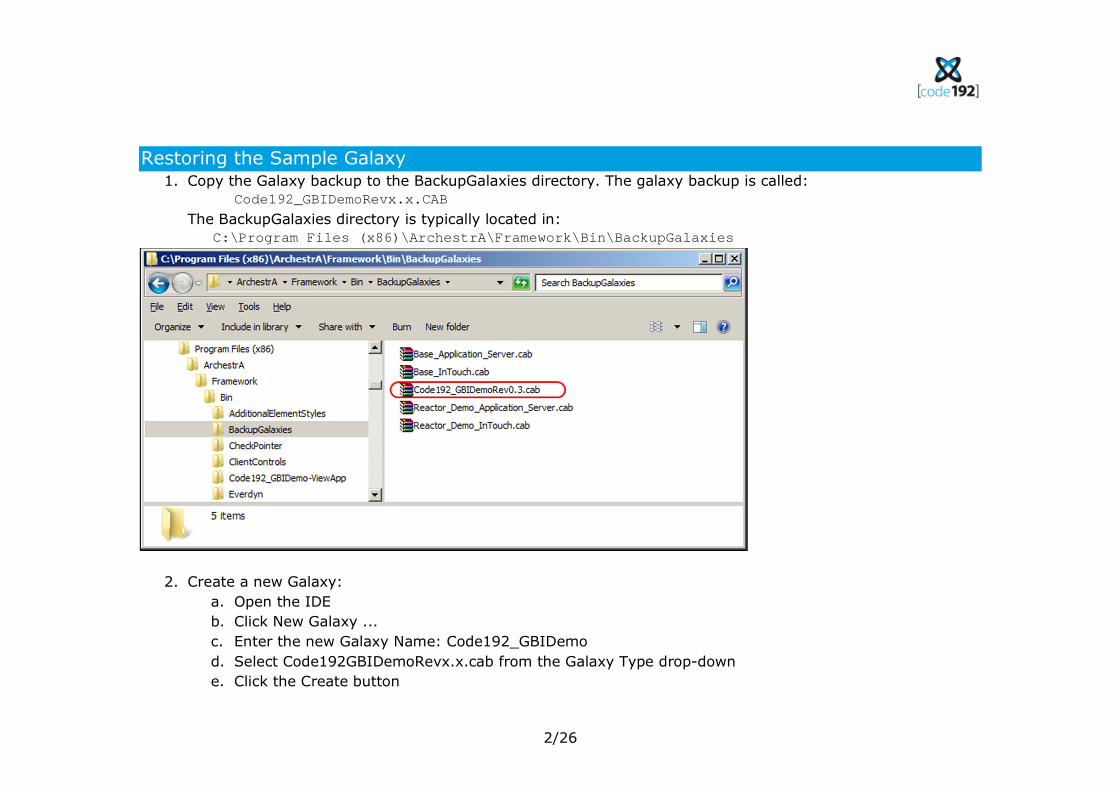
Restoring the Sample Galaxy 1. Copy the Galaxy backup to the BackupGalaxies directory. The galaxy backup is called:
Code192_GBIDemoRevx.x.CAB
The BackupGalaxies directory is typically located in:
C:\Program Files (x86)\ArchestrA\Framework\Bin\BackupGalaxies
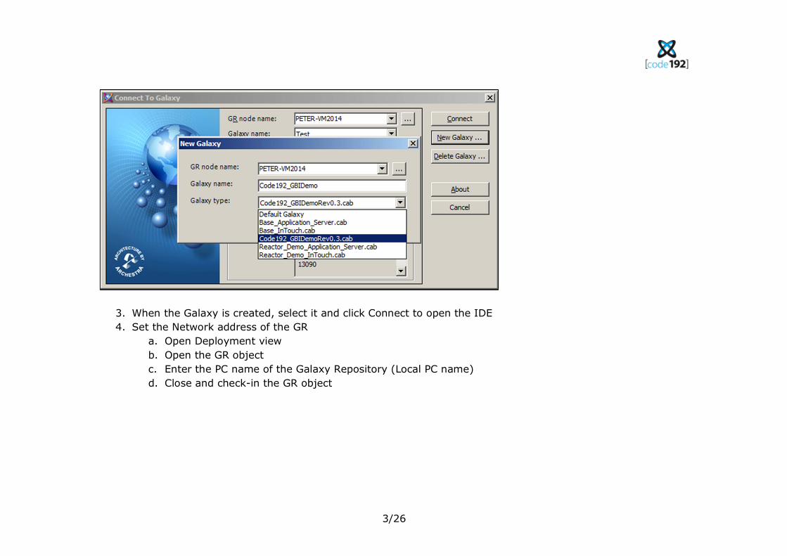
2. Create a new Galaxy:
a. Open the IDE
b. Click New Galaxy ...
c. Enter the new Galaxy Name: Code192_GBIDemo
d. Select Code192GBIDemoRevx.x.cab from the Galaxy Type drop-down
e. Click the Create button
3/26
3. When the Galaxy is created, select it and click Connect to open the IDE
4. Set the Network address of the GR
a. Open Deployment view
b. Open the GR object
c. Enter the PC name of the Galaxy Repository (Local PC name)
d. Close and check-in the GR object
4/26
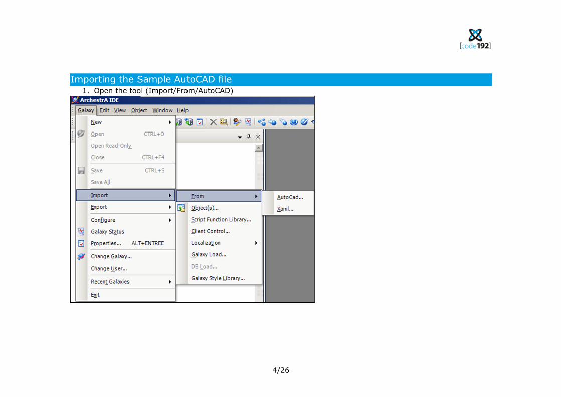
Importing the Sample AutoCAD file 1. Open the tool (Import/From/AutoCAD)
5/26
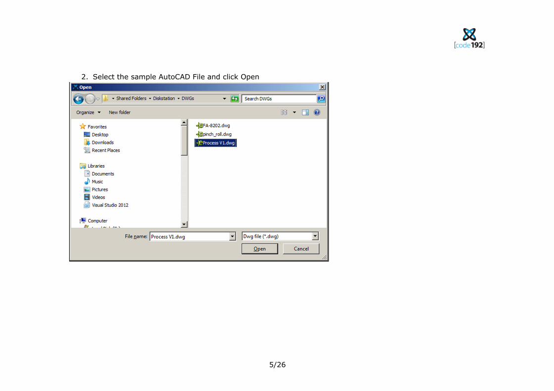
2. Select the sample AutoCAD File and click Open
6/26
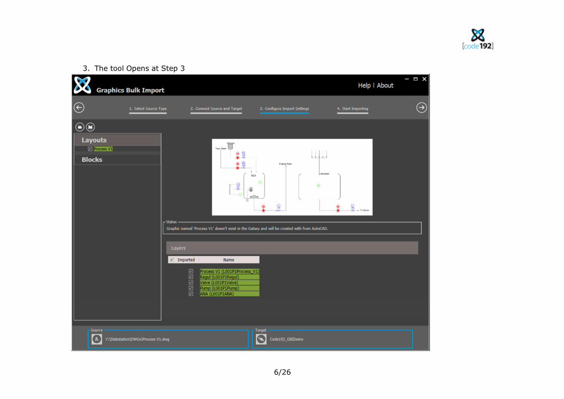
3. The tool Opens at Step 3
7/26
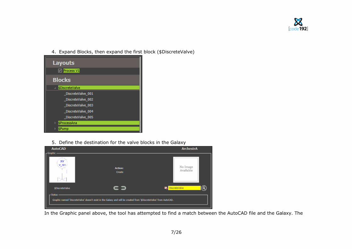
4. Expand Blocks, then expand the first block ($DiscreteValve)
5. Define the destination for the valve blocks in the Galaxy
In the Graphic panel above, the tool has attempted to find a match between the AutoCAD file and the Galaxy. The
8/26
block has been named $DiscreteValve by a helpful draftsperson. While a block is similar to an ArchestrA template,
the graphical representation needs to map to a symbol. Legal names for symbols might be DiscreteValue or
$DiscreteValue.Mimic. The tool has recognised that $DiscreteValve is not a legal symbol name, so has decided to
import the symbol into the Graphic Toolbox and has corrected the name to DiscreteValve. Note the symbol icon. To
show the user that a correction has been automatically applied, the text is highlighted in Yellow.
Let’s go ahead and correct this here. There is no need to edit the AutoCAD file.
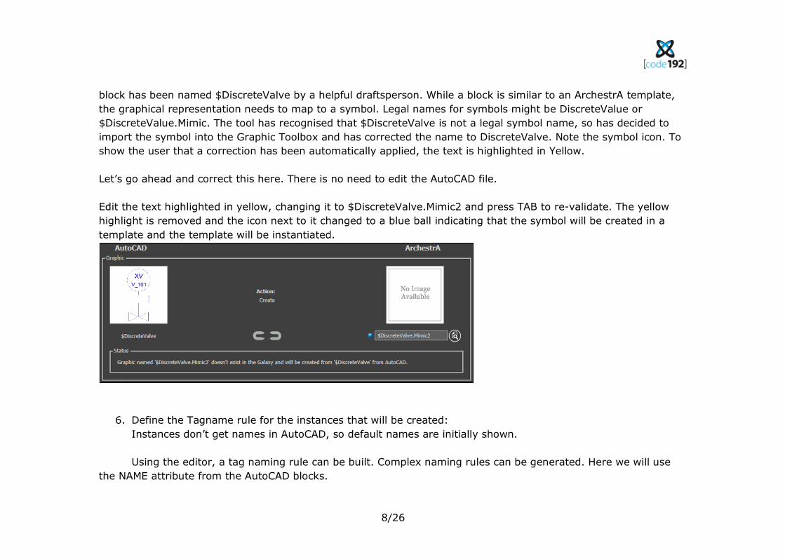
Edit the text highlighted in yellow, changing it to $DiscreteValve.Mimic2 and press TAB to re-validate. The yellow
highlight is removed and the icon next to it changed to a blue ball indicating that the symbol will be created in a
template and the template will be instantiated.
6. Define the Tagname rule for the instances that will be created:
Instances don’t get names in AutoCAD, so default names are initially shown.
Using the editor, a tag naming rule can be built. Complex naming rules can be generated. Here we will use
the NAME attribute from the AutoCAD blocks.
9/26
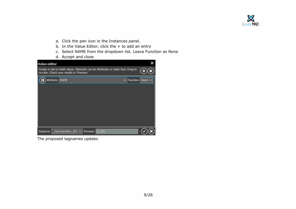
a. Click the pen icon in the Instances panel.
b. In the Value Editor, click the + to add an entry
c. Select NAME from the dropdown list. Leave Function as None
d. Accept and close
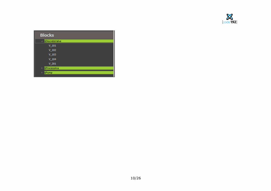
The proposed tagnames update:
10/26
11/26
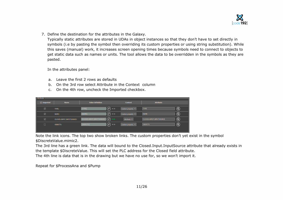
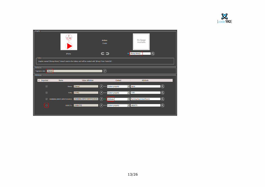
7. Define the destination for the attributes in the Galaxy.
Typically static attributes are stored in UDAs in object instances so that they don’t have to set directly in
symbols (i.e by pasting the symbol then overriding its custom properties or using string substitution). While
this saves (manual) work, it increases screen opening times because symbols need to connect to objects to
get static data such as names or units. The tool allows the data to be overridden in the symbols as they are
pasted.
In the attributes panel:
a. Leave the first 2 rows as defaults
b. On the 3rd row select Attribute in the Context column
c. On the 4th row, uncheck the Imported checkbox.
Note the link icons. The top two show broken links. The custom properties don’t yet exist in the symbol
$DiscreteValue.mimic2.
The 3rd line has a green link. The data will bound to the Closed.Input.InputSource attribute that already exists in
the template $DiscreteValue. This will set the PLC address for the Closed field attribute.
The 4th line is data that is in the drawing but we have no use for, so we won’t import it.
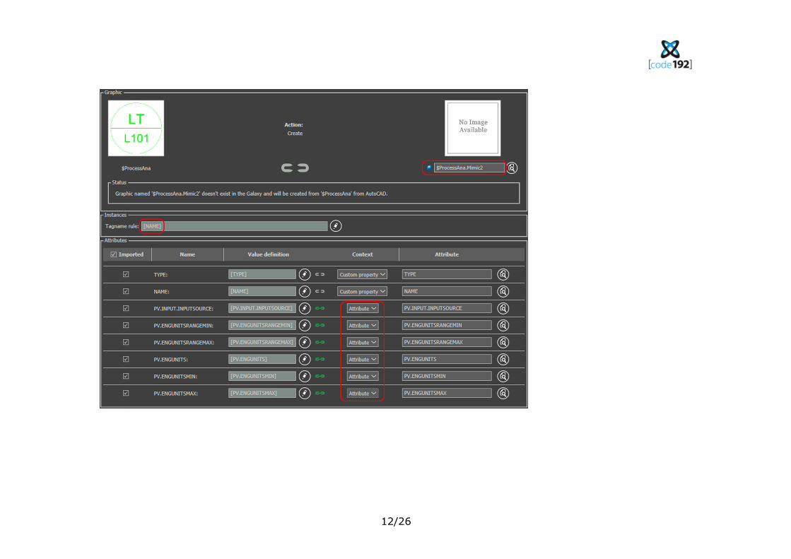
Repeat for $ProcessAna and $Pump
12/26
13/26
14/26
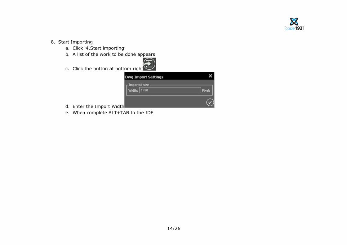
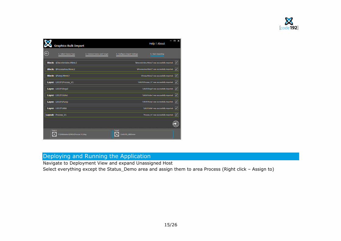
8. Start Importing
a. Click ‘4.Start importing’
b. A list of the work to be done appears
c. Click the button at bottom right
d. Enter the Import Width
e. When complete ALT+TAB to the IDE
15/26
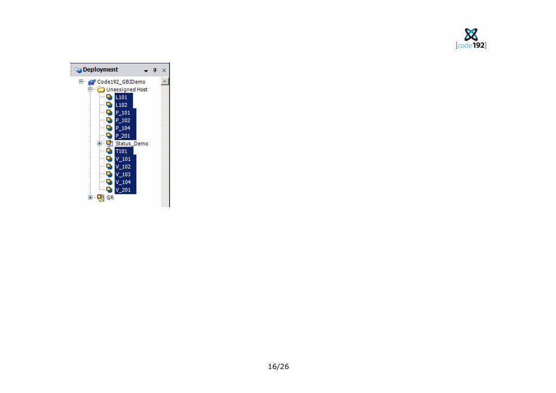
Deploying and Running the Application Navigate to Deployment View and expand Unassigned Host
Select everything except the Status_Demo area and assign them to area Process (Right click – Assign to)
16/26
17/26
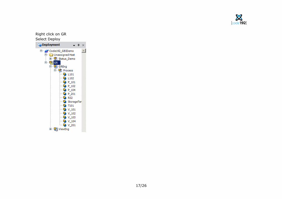
Right click on GR
Select Deploy
18/26
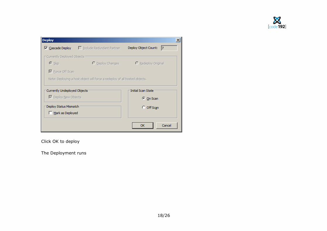
Click OK to deploy
The Deployment runs
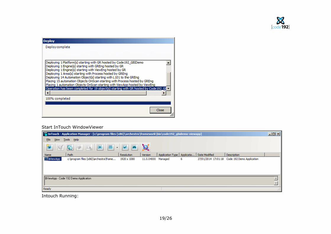
19/26
Start InTouch WindowViewer
Intouch Running:
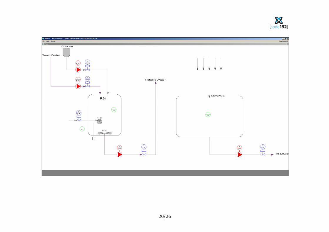
20/26
21/26
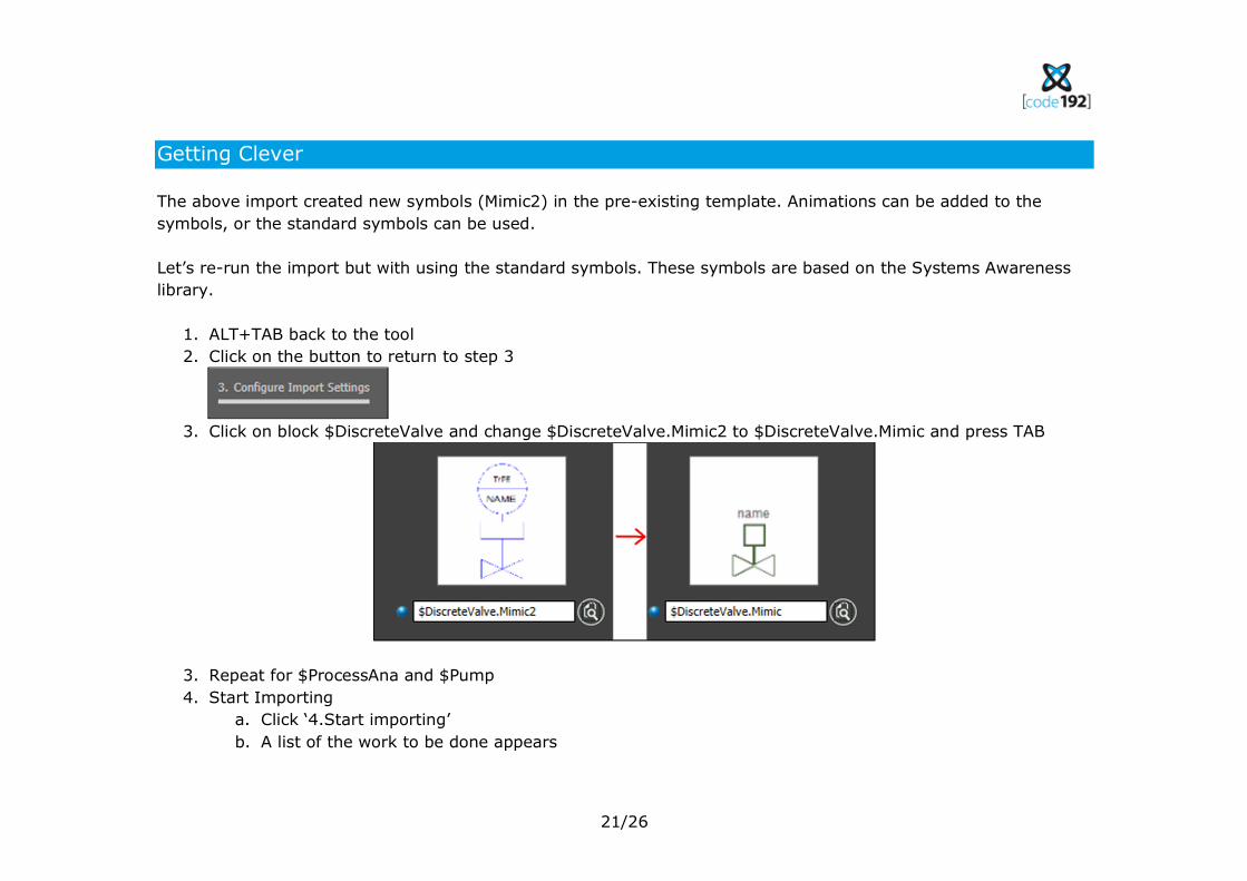
Getting Clever
The above import created new symbols (Mimic2) in the pre-existing template. Animations can be added to the
symbols, or the standard symbols can be used.
Let’s re-run the import but with using the standard symbols. These symbols are based on the Systems Awareness
library.
1. ALT+TAB back to the tool
2. Click on the button to return to step 3
3. Click on block $DiscreteValve and change $DiscreteValve.Mimic2 to $DiscreteValve.Mimic and press TAB
3. Repeat for $ProcessAna and $Pump
4. Start Importing
a. Click ‘4.Start importing’
b. A list of the work to be done appears
22/26
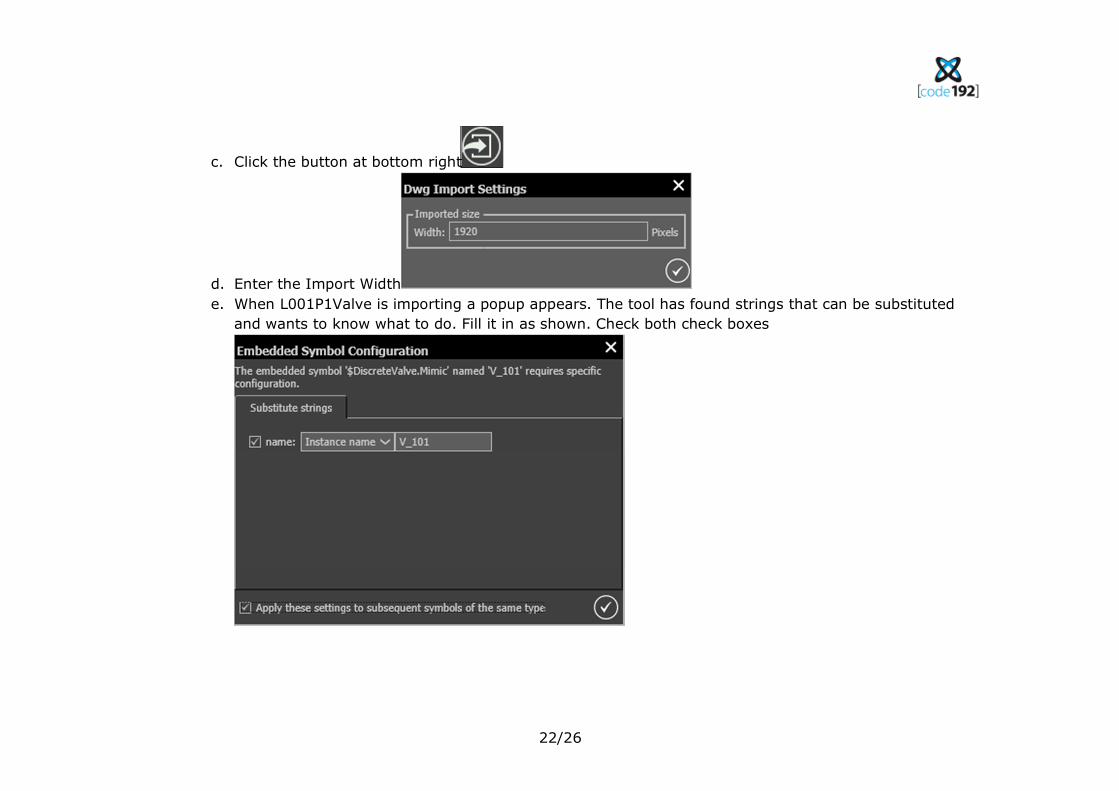
c. Click the button at bottom right
d. Enter the Import Width
e. When L001P1Valve is importing a popup appears. The tool has found strings that can be substituted
and wants to know what to do. Fill it in as shown. Check both check boxes
23/26
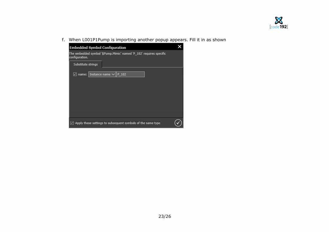
f. When L001P1Pump is importing another popup appears. Fill it in as shown
24/26
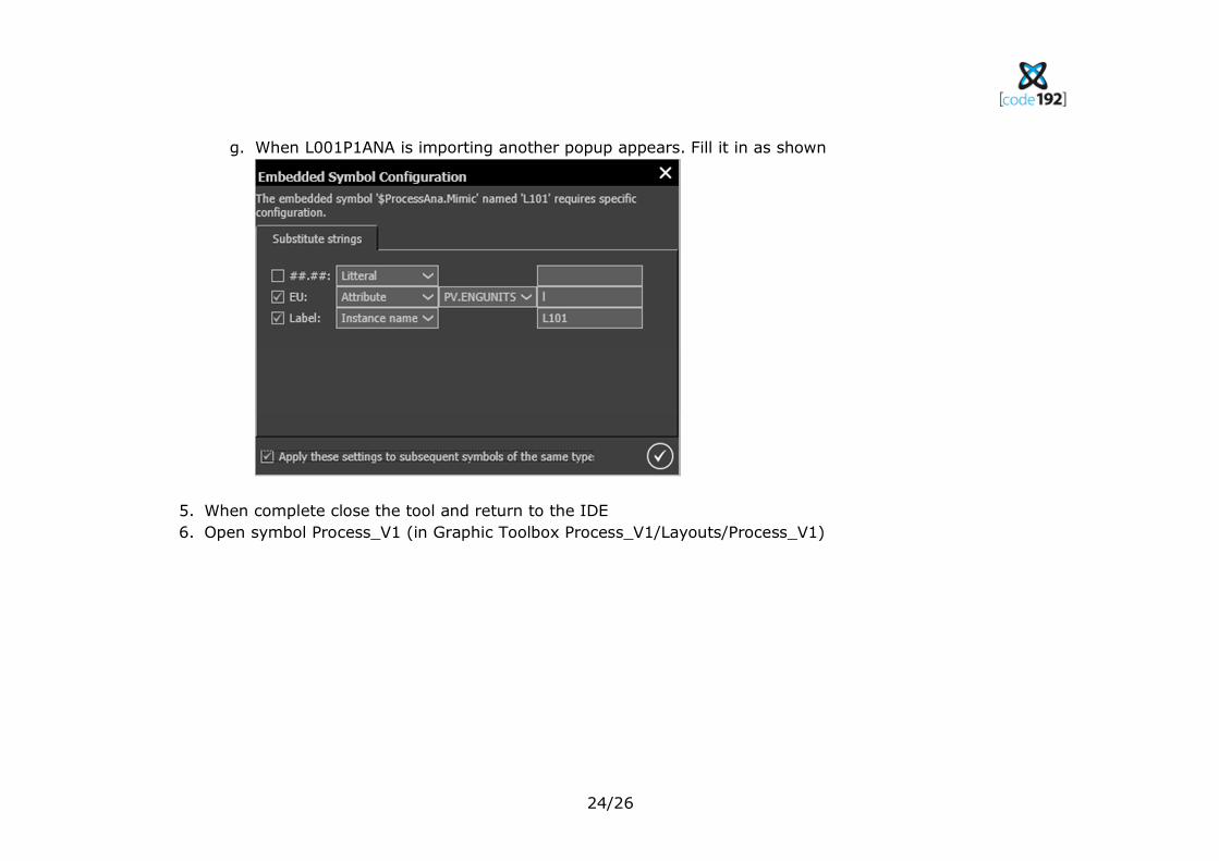
g. When L001P1ANA is importing another popup appears. Fill it in as shown
5. When complete close the tool and return to the IDE
6. Open symbol Process_V1 (in Graphic Toolbox Process_V1/Layouts/Process_V1)
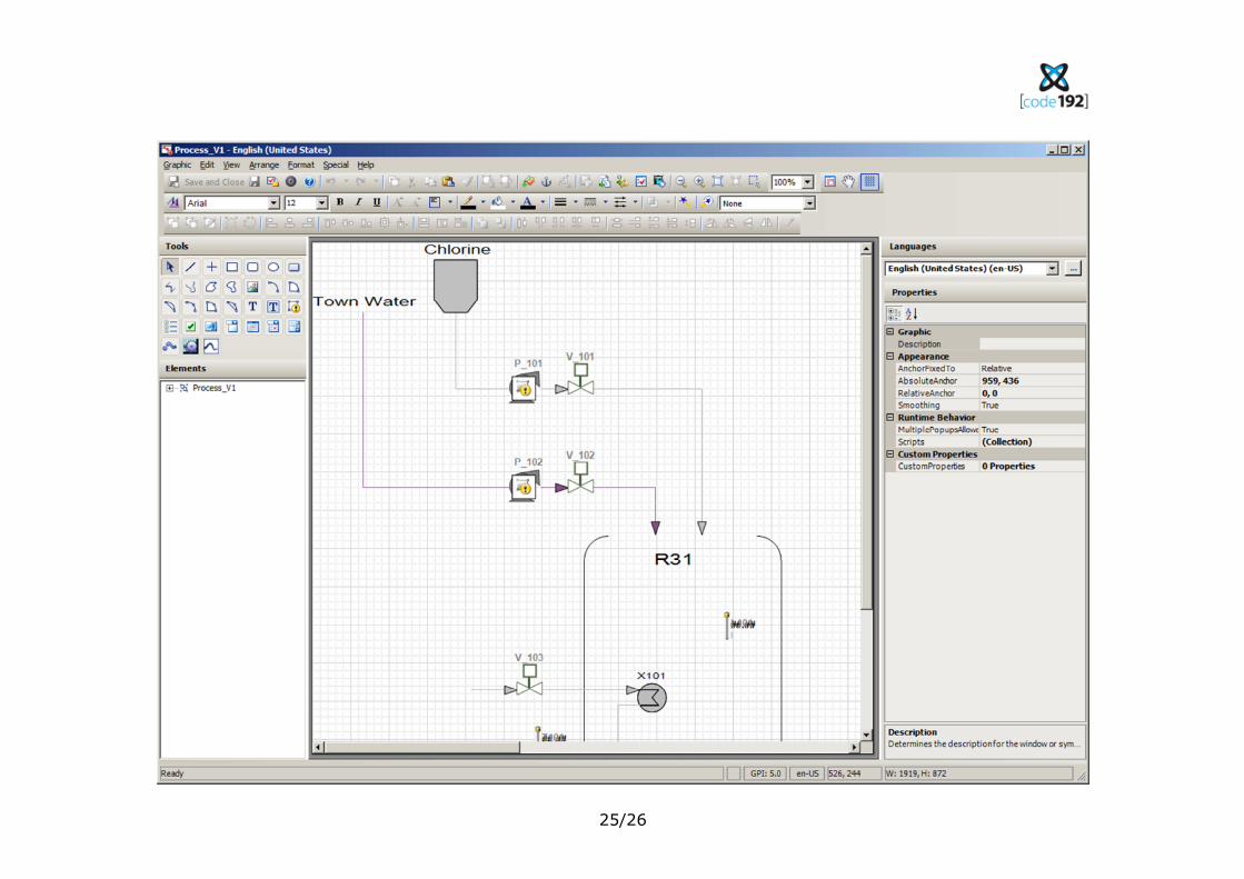
25/26
26/26
Note how the symbols are no longer the symbols in the AutoCAD file. They have been replaced with the symbols
from the Template. Note also that in design view the names of the symbols have been added by the tool. This is
often too tedious and error prone to do my hand, but makes navigating large screens much faster.