Building Better Outcomes
12
LONG-SPAN BRIDGE SERIES Building Better Outcomes WITH REINFORCED CONCRETE Going The Distance For Long-Span Bridges Photo: ©FIGG
Transcript of Building Better Outcomes

LONG-SPAN BRIDGE SERIES
Building Better Outcomes with ReinfORced cOncRete
Going the distance for Long-Span Bridges
Photo: ©FIGG
Reinforced concrete: Goes the
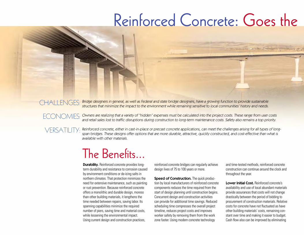
Bridge designers in general, as well as Federal and state bridge designers, have a growing function to provide sustainable structures that minimize the impact to the environment while remaining sensitive to local communities’ history and needs.
Owners are realizing that a variety of “hidden” expenses must be calculated into the project costs. These range from user costs and retail sales lost to traffic disruptions during construction to long-term maintenance costs. Safety also remains a top priority.
Reinforced concrete, either in cast-in-place or precast concrete applications, can meet the challenges arising for all types of long-span bridges. These designs offer options that are more durable, attractive, quickly constructed, and cost-effective than what is available with other materials.
CHALLENGES:
ECONOMIES:
VERSATILITY:
the Benefits...Durability. Reinforced concrete provides long-term durability and resistance to corrosion caused by environment conditions or de-icing salts in northern climates. That protection minimizes the need for extensive maintenance, such as painting or rust prevention. Because reinforced concrete offers a monolithic and durable design, moreso than other building materials, it lengthens the time needed between repairs, saving labor. Its spanning capabilities minimize the required number of piers, saving time and material costs, while lessening the environmental impact. Using current design and construction practices,
reinforced concrete bridges can regularly achieve design lives of 75 to 100 years or more.
Speed of Construction. The quick produc-tion by local manufacturers of reinforced concrete components reduces the time required from the start of design planning until construction begins. Concurrent design and construction activities can provide for additional time savings. Reduced scheduling time compresses the overall project timeline, reduces project costs and improves worker safety by removing them from the work zone faster. Using modern concrete technology
and time-tested methods, reinforced concrete construction can continue around the clock and throughout the year.
Lower Initial Cost. Reinforced concrete’s availability and use of local abundant materials provide assurances that costs will not change drastically between the period of bidding to procurement of construction materials. Relative costs for concrete have not fluctuated as have other building materials’ costs, remaining con-stant over time and making it easier to budget. Cash flow also can be improved by eliminating

distance for Long-Span Bridges
initial expenses and minimizing transportation and staging logistics. By standardizing details, costs for embankment work, casting forms, and other equipment, operations can be minimized. Reinforced concrete construction provides a short design-to-build interval and allows quick completion, reducing construction risks and financing costs.
Lower Long-Term Costs. The durability provided by reinforced concrete minimizes long-term budgets for maintenance labor and materi-als. The long service life that can be achieved with reinforced concrete means replacement of the structure won’t need to be considered for generations.
Design Flexibility. The ability of reinforced concrete construction to adapt easily to field changes speeds construction and minimizes delays. New technologies, including spliced girders and segmental construction, extend the lengths of bridge spans. These approaches minimize the number of piers and meet specific site challenges. Reinforced concrete also offers
the capability to create shallow profiles, which can provide greater underpass openings and access for waterways or roadways.
Architectural Enhancements. Reinforced concrete can replicate a variety of finishes in-cluding stone and brickwork, at lower cost and with better durability than the actual materi-als. It also can achieve a multitude of shapes, including contemporary or historic-looking
arches, and include intricate railings, pedestrian alcoves, benches, and other amenities. This ver-satility ensures the bridge complements existing structures or neighborhoods or replicates the
original structure’s historic design.
Sustainable Design. Reinforced concrete uses locally available and manufactured materi-als, minimizing transportation and staging
costs. It is typically cast to specifications, with little excess produced. Waste created can be recycled for further use. Reinforced concrete’s high-strength capabilities can minimize the number of piers, saving material and reducing environmental impact.
The reinforcing bar used in concrete consists of nearly 100% recycled material, while con-crete mixtures typically incorporate industrial co-products such as fly ash, ground granulated blast furnace slag, silica fume, and other supplemental cementitious materials. These reduce the amount of cement required while significantly improving durability. Many cement and ready-mix concrete plants have instituted water-recycling programs and other processes to further reduce the impact of manufactur-ing on the environment. At the end of the structure’s useful service life, there is the option for concrete to be recycled as a substitute for natural aggregate materials.
Greater Fire Resistance. Reinforced concrete’s inherent durability resists heat from
intense fires caused by vehicle accidents. In many cases, damaged concrete bridges require only minor repairs to restore them to full use. With reinforced concrete, fire protection is an integral part of the structural element.
Seismic Design. Reinforced concrete struc-tures can be designed to withstand seismic events in any seismic zone, ensuring the bridge’s infrastructure remains serviceable even if an earthquake strikes. Concrete footings, piers and superstructures can work together to save lives and maintain traffic access.
Concrete Decks. Reinforced concrete decks provide a smooth, consistent driving surface. New technologies are speeding up installation times, improving durability and enhancing the ride quality. These decks represent the final part of a complete concrete bridge design that provides single-source responsibility for the key components.
A Quick, Permanent ReplacementI-35W Bridge, Minneapolis, Minnesota
i-35w Bridge over the Mississippi River
LocationMinneapolis, Minnesota
OwnerMinnesota Department of Transportation
DesignerFIGG
Tallahassee, Florida
Contractor Joint Venture
Flatiron Construction Corporation Longmont, Colorado
Manson Construction Company Seattle, Washington
Reinforcing Bar FabricatorGerdau Ameristeel
West Allis, Wisconsin
Epoxy Coating FabricatorSimcote
St. Paul, Minnesota
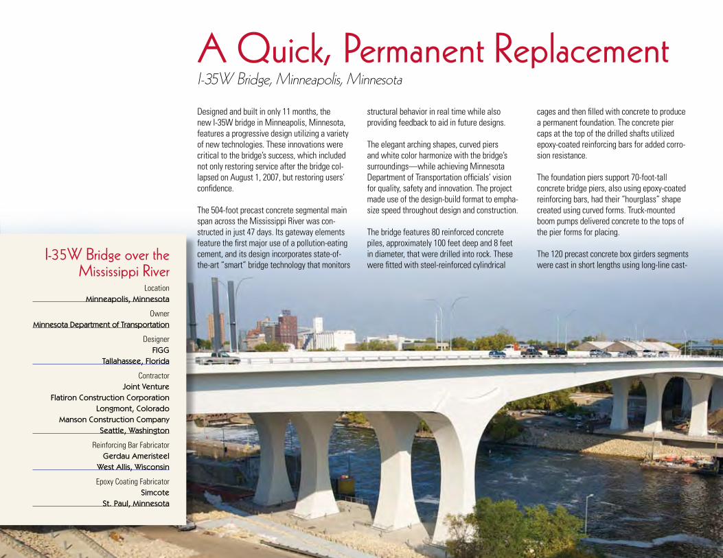
Designed and built in only 11 months, the new I-35W bridge in Minneapolis, Minnesota, features a progressive design utilizing a variety of new technologies. These innovations were critical to the bridge’s success, which included not only restoring service after the bridge col-lapsed on August 1, 2007, but restoring users’ confidence.
The 504-foot precast concrete segmental main span across the Mississippi River was con-structed in just 47 days. Its gateway elements feature the first major use of a pollution-eating cement, and its design incorporates state-of-the-art “smart” bridge technology that monitors
structural behavior in real time while also providing feedback to aid in future designs.
The elegant arching shapes, curved piers and white color harmonize with the bridge’s surroundings—while achieving Minnesota Department of Transportation officials’ vision for quality, safety and innovation. The project made use of the design-build format to empha-size speed throughout design and construction.
The bridge features 80 reinforced concrete piles, approximately 100 feet deep and 8 feet in diameter, that were drilled into rock. These were fitted with steel-reinforced cylindrical
cages and then filled with concrete to produce a permanent foundation. The concrete pier caps at the top of the drilled shafts utilized epoxy-coated reinforcing bars for added corro-sion resistance.
The foundation piers support 70-foot-tall concrete bridge piers, also using epoxy-coated reinforcing bars, had their “hourglass” shape created using curved forms. Truck-mounted boom pumps delivered concrete to the tops of the pier forms for placing.
The 120 precast concrete box girders segments were cast in short lengths using long-line cast-

Reinforced-concrete framing helped reduce energy consumption in the bridge by 90%.
ing beds set up on the existing roadway and then delivered to a staging area for erection. Adjacent side spans constructed over land feature cast-in-place concrete elements, using the same box girder shape.
High-strength, high-performance concrete was placed over mats of epoxy-coated reinforcing steel, with high-strength steel post-tensioning strands located along the length and width of the bridge. Transverse post-tensioning tendons compress the top slab, providing additional strength and extending the life of the driving surface by keeping crack widths tight. Multi-strand tendons, consisting of 19 to 27 strands, run longitudinally along the bridge’s length creating levels of design redundancy.
The use of precast, segmental box girders provided for long, open spans that eliminated the need for piers to be placed in the river,
minimizing the environmental impact. Utilities, data monitors, lighting conduits, and drainage pipes are hidden in the box girders—providing safe and easy maintenance access while offer-ing pleasing aesthetics.
The three cast-in-place bridge spans located over land were constructed simultaneously with the precast segments spanning the river. This saved considerable time in the schedule and ensured the project met its aggressive opening date.
Economy and efficiency were maintained, even on a tight schedule, through the use of various reinforcing bar diameter, steel strength, and concrete strength combinations. The innovative geometry of this project was easily constructed through the use of reinforced concrete. Approx-imately 10.9 million pounds of steel reinforcing bar were used in the project.
Total project size:
1,223 ft Overall Span 505 ft Main Span 315 ft / 248 ft Back Spans 147 ft Approach Span
Total project cost:
$234 million
i-35w Bridge by the numbers.
Photos: ©FIGG
Photo: Shutterstock

Victory Bridge replaced an aging swing-span bridge and represents the first concrete segmental bridge built in New Jersey. The twin 3,971-foot structures, which honors World War II servicemen, feature fully match-cast, 440-foot main spans, a record in the United States at the time. Built sequentially to maintain traffic during construction, the first bridge opened to traffic 15 months after notice to proceed, while the second structure opened only nine months later — ahead of schedule.
The aggressive completion was achieved with the use of precast reinforced concrete box piers, some as tall as 100 feet, which were each assembled in just one day. The approach spans then were erected using span-by-span construction concurrent with erection of the main span unit, which was built using the balanced-cantilever method.
The construction team also took advantage of the using the existing 3-D CAD production drawings which eliminated the time and money needed to prepare and review new shop drawings. The drawings included details on reinforcing bar bends, segment geometry and tendon stressing.
Total project cost:
$109.1 million
Victory Bridge by the numbers.
Bridging endurance and GratitudeVictory Bridge, Perth Amboy and Sayreville, New Jersey
Total project size:
3,971 ft Overall Span 440 ft Main Span (2) 330 ft Back Spans
3-d color cAd drawing of a main span pier segment half. Various colors were used to indicate different reinforcing bar sizes, post-tensioning ducts and other structural framing details.

The 440-foot main span provides 355 feet of horizontal clearance, an increase of 227 feet from the previous structure. This dramatically improved safety and traffic flow. Superstruc-ture segments vary in depth from 21 feet at the piers to 10 feet at mid-span, creating an arching effect over the river. The approach spans feature a constant depth, which allowed for ease of construction of the span-by-span sequence.
A 1¼-inch layer also was cast with the seg-ment to provide a durable, integral wearing surface. All superstructure segments were cast with a ½-inch sacrificial layer of concrete
on the top slab. After erection was completed, the top slabs were ground to achieve the desired surface for rideability.
The design and use of reinforced concrete produced a bridge that was cost efficient to construct ($220 per square foot in an expensive labor market), offers a service life exceeding 100 years, and projects a dramatic image that will reflect the history of the former swing-span bridge at the site. Four concrete obelisks, two at each end, display the original bronze markers, along with new ones, rededicating the bridge to the World War II veterans’ honor.
Victory BridgeLocation
Perth Amboy and Sayreville, New Jersey
OwnerNew Jersey Department of Transportation
DesignerFIGG
Tallahassee, Florida
Contractor George Harms Construction Company
Farmingdale, New Jersey
Reinforcing Bar FabricatorHarris Rebar
Bethlehem, Pennsylvania
with a service life exceeding 100 years, it offers unique aesthetics that honor new Jersey veterans who served in wwi.

The NW Maple Avenue Bridge provides a link for the City of Redmond across Dry Canyon, a scenic natural feature providing recreational space for citizens. City officials wanted to create a structure that presented minimal interference with this open space while also providing a pleasing appearance suited for its surroundings.
The 780-foot-long, cast-in-place concrete design consists of three continuous 210-foot deck arch spans and two 75-foot post-tensioned approach spans. The arches support a double-tee stemmed deck section, with the two stems matching the trans-
concrete reinforced steel arches add to the beauty and functionality of the bridge by conforming to the canyon.
Maple Avenue BridgeLocation
Redmond, Oregon
OwnerCity of Redmond
DesignerOBEC Consulting Engineers
in conjunction with Jiri Strasky, Consultng Engineer
Eugene, Oregon
Contractor Cascade Bridge LLC
Vancouver, Washington
Reinforcing Bar FabricatorFarwest Steel,
Eugene, Oregon R2M2 Rebar & Stressing
Portland, Oregon
natural SpanMaple Avenue Bridge, Redmond, Oregon

verse spacing of the arch ribs below. The superstructure section for the arch spans con-tinues across the approach spans, where the longer spans of the shallow beams required post-tensioning. All other elements, including substructure, arches, columns, and decks, were conventionally reinforced.
Double columns were placed at each arch rib end, with spandrel columns placed midway between rib ends and composite crown segments. The columns are monolithic, with T-beams above and arch ribs or footings below. They were designed as structurally slender members along the bridge and wide members transverse to the bridge. This created unbraced transverse rigid frames. The arch ribs are composite T-beams with 50 foot mid-spans.
Each arch span has a different profile to provide a uniform length with variable rise relative to each arch support, conforming to the canyon’s topography. The two arch ribs are fixed to the footings at the ends of the three-span series, and are pinned to and continuous across the end footings at the intermediate bents. This arrangement allows the ribs to appear to lightly touch the canyon floor at the interior bents.
Intermediate deck diaphragms, transverse beams, and transverse arch braces were made unnecessary by the design approach, contributing to the openness of the structure. Spandrel and bent columns were designed to be architecturally similar, with their slender dimensions relative to height nearly constant.
At the bents, the column pair is one column architecturally but two columns function-ally, with one of the pair on each side of a transverse deck expansion joint.
Cast-in-place reinforced concrete easily accommodated the variability required in the arch shapes, with special formwork needed only to create the arch curvature that pro-vided the unique and aesthetically pleasing final shape.
Total project cost:
$8.3 million
Maple Avenue Bridge by the numbers.
Photos: OBEC Consulting Engineers
Total project size:
780 ft Overall Span (3) 210 ft Arch Spans (2) 75 ft Approach Spans

Photo: Kiewit Pacific Company
Photo: T.Y. Lin International
Unshakeable LifelineBenicia-Martinez Bridge, Martinez, California
The new five-lane, 7,500-foot-long Benicia-Martinez Bridge serves northern California as a lifeline bridge in a seismically active region. The “lifeline” designation requires the structure to remain structurally functional after a major earthquake. To achieve that goal, designers produced the first cast-in-place, reinforced concrete segmental bridge built in California in 20 years.
Lightweight, high-performance reinforced concrete was used for the superstructure to
reduce the loading impact on the piers during a seismic event. The reinforced concrete had to weigh approximately 20% less than normal structural concrete while achieving a strength requirement of 10,000 psi and a stringent modulus of elasticity to limit deflection. After more than 100 test mixes and multiple field trials, a concrete mix was selected.
Grade 60 reinforcing bar was used in the project. The reinforcing bar was epoxy coated to protect against corrosion, as required by California statutes for structures built over water. Special guidance from consulting engineers was used to develop detailing and spacing of the reinforcing bars to ensure the most effective design.
Total project cost:
$660 million
Benicia-Martinez Bridgeby the numbers.
epoxy-coated reinforcing bar was used to provide added protection against corrosion.
Total project size:
7,434 ft Overall Span 1,692 ft / 2,113 ft / 2,662 ft / 952 ft Spans
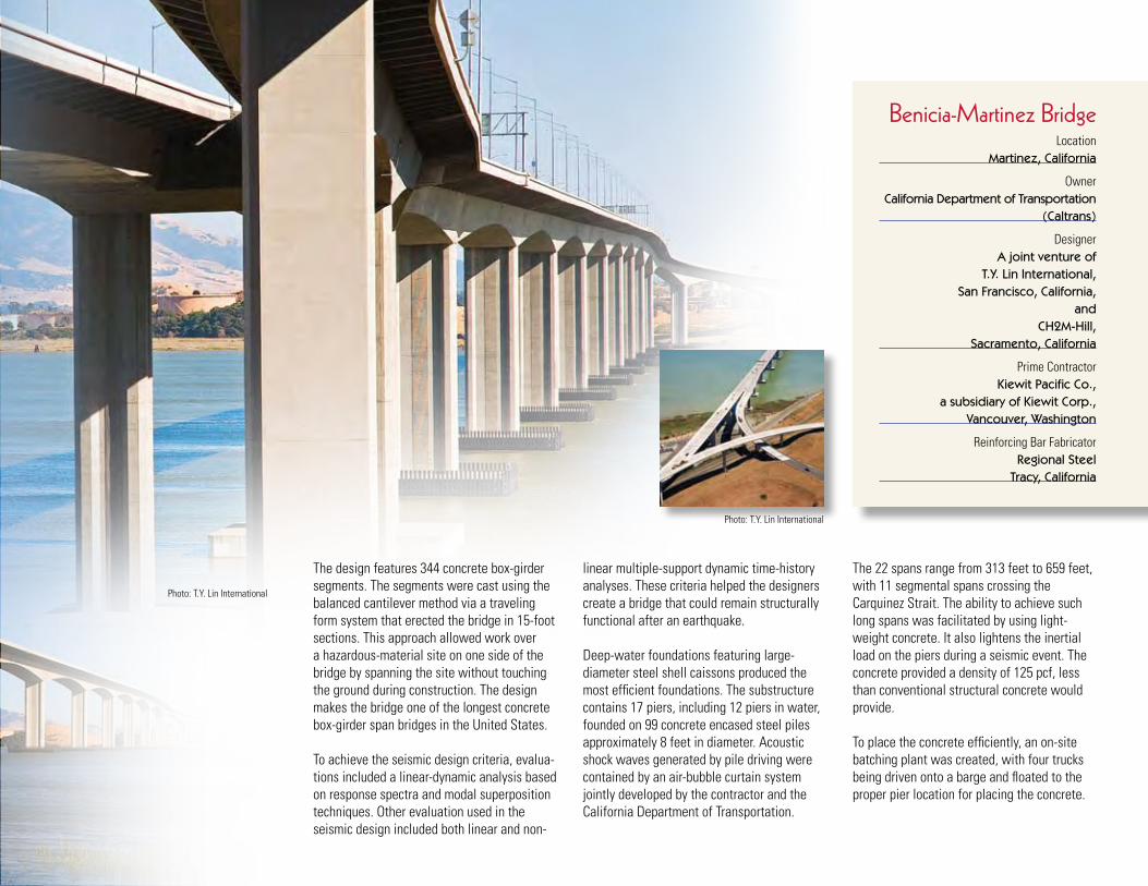
Photo: T.Y. Lin International
Photo: T.Y. Lin International
The design features 344 concrete box-girder segments. The segments were cast using the balanced cantilever method via a traveling form system that erected the bridge in 15-foot sections. This approach allowed work over a hazardous-material site on one side of the bridge by spanning the site without touching the ground during construction. The design makes the bridge one of the longest concrete box-girder span bridges in the United States.
To achieve the seismic design criteria, evalua-tions included a linear-dynamic analysis based on response spectra and modal superposition techniques. Other evaluation used in the seismic design included both linear and non-
linear multiple-support dynamic time-history analyses. These criteria helped the designers create a bridge that could remain structurally functional after an earthquake.
Deep-water foundations featuring large-diameter steel shell caissons produced the most efficient foundations. The substructure contains 17 piers, including 12 piers in water, founded on 99 concrete encased steel piles approximately 8 feet in diameter. Acoustic shock waves generated by pile driving were contained by an air-bubble curtain system jointly developed by the contractor and the California Department of Transportation.
The 22 spans range from 313 feet to 659 feet, with 11 segmental spans crossing the Carquinez Strait. The ability to achieve such long spans was facilitated by using light-weight concrete. It also lightens the inertial load on the piers during a seismic event. The concrete provided a density of 125 pcf, less than conventional structural concrete would provide.
To place the concrete efficiently, an on-site batching plant was created, with four trucks being driven onto a barge and floated to the proper pier location for placing the concrete.
Benicia-Martinez BridgeLocation
Martinez, California
OwnerCalifornia Department of Transportation
(Caltrans)
DesignerA joint venture of
T.Y. Lin International, San Francisco, California,
and CH2M-Hill,
Sacramento, California
Prime ContractorKiewit Pacific Co.,
a subsidiary of Kiewit Corp., Vancouver, Washington
Reinforcing Bar FabricatorRegional Steel
Tracy, California

GREAT LAKESREGION
ATLANTICREGION
CENTRALREGION
GREATER SOUTHWESTERNREGION
SOUTHERNREGION
WESTERNREGION
For more information on how reinforced concrete can assist with your design goals, contact:
933 North Plum Grove Road ❘ Schaumburg IL 60173847.517.1200 ❘ www.crsi.org
©2009 CRSI
Atlantic Region ManagerMichael Mota, 856-264-3851 [email protected]
Central Region ManagerJack Gibbons, 847-517-1200 [email protected]
Great Lakes Region ManagerTony Johnson, 248-726-0500 [email protected]
Southern Region ManagerSteven R. Hawkins, 772-321-6880 [email protected]
Greater Southwestern Region ManagerJohn B. Turner, 214-281-8830 [email protected]
Western Region ManagerBethany Hennings, 209-499-4740 [email protected]
Pacific Northwest ManagerJim Fullerton, 360-933-4126 [email protected]
Regional Offices Nationwide.
Photo: OBEC Consulting Engineers