
Building a 1/5 Scale M-4 Sherman · PDF fileBuilding a 1/5 Scale M-4 Sherman Tank Riding Toy...
81
Building a 1/5 Scale M-4 Sherman Tank Riding Toy "I really have a secret satisfaction in being considered rather mad." - W. Heath Robinson 2 st Edition June 15, 2003 © 2003 W. E. Johns
Transcript of Building a 1/5 Scale M-4 Sherman · PDF fileBuilding a 1/5 Scale M-4 Sherman Tank Riding Toy...

Building a 1/5 ScaleM-4 Sherman Tank
Riding Toy
"I really have a secret satisfaction in beingconsidered rather mad."
- W. Heath Robinson
2st EditionJune 15, 2003
© 2003 W. E. Johns

2
Disclaimer
YOU AGREE TO ASSUME ALL RISK AND LIABILITY RESULTINGFROM THE USE OR MISUSE OF ANY INFORMATION CONTAINED
HEREIN. YOU ALSO AGREE TO INDEMNIFY ME IN THE EVENT OFANY LOSS INCURRED BY ANYONE AS A CONSEQUENCE OF THE
USE OR MISUSE OF ANY INFORMATION CONTAINED HEREIN, ANDTO DEFEND ME AGAINST ANY SUIT BROUGHT BY ANY THIRD
PARTY FOR ANY REASON BASED UPON THIS AGREEMENT ORUPON THE USE OR MISUSE OF ANY INFORMATION CONTAINED
HEREIN.
USE OR MISUSE OF ANY INFORMATION CONTAINED HEREINCONSTITUTES ACCEPTANCE OF THESE TERMS.

3
Table of Contents
Disclaimer.......................................... 2Table of Contents................................... 3Introduction........................................ 4
Safety............................................ 7Part I: Cutting the Plywood......................... 8
Cutting Layout.................................... 9Parts Details.................................... 10
Part II: Assembling the Hull....................... 15Part III: Assembling the Suspension................ 30
Bogies and Road Wheels........................... 30Drive Axles, or Half-Shafts...................... 36Track Sprocket................................... 38Rear Axle and Idler Wheels....................... 42Track............................................ 43Tank Cradle and Lifting Rig (optional)........... 46
Part IV: The Turret................................ 47Turret Plans..................................... 48The Gun.......................................... 56Paint............................................ 57
Part V: The Electrical System...................... 58Running 12v Accessories on 24v................... 58Wire............................................. 59Batteries........................................ 59Motor Selection.................................. 62Installing the Motors............................ 62Motor Control.................................... 66Battery Compartment Fan.......................... 71Lights........................................... 72
Conclusion......................................... 75Appendix I: Sources................................ 76Appendix II: Glossary.............................. 77Appendix III: Motor Calculations................... 79

4
IntroductionIt would probably be best to not call this a “model”, but rather a
“caricature”, as it is not completely anatomically correct. For example,the turret is too far back (to increase legroom), the rear end is all messedup (to make room for the batteries), 6 teeth on the sprocket instead of13, etc. I had to find a compromise between realism and buildability, andbetween detail and durability. However, it looks like a Sherman tank –anyone who has ever seen a Sherman will instantly recognize it. Onlytrue Sherman experts will be able to pick out the flaws.
This project took me well over two hundred hours, perhaps asmany as three hundred, and this doesn’t include time I spent onresearch! I started in June of 2002, thinking that I had plenty of time toget it finished as a birthday present for my 6-year-old son in November,but I didn’t quite make it in time. It should take you considerably lesstime than it took me – I think at least half of my time was spent juststaring at it, deep in thought, solving some design problem or another.

5
With luck I’ve remembered to include all of my solutions in this text, soyou will do considerably less staring than I have.
The tank can be built as a remote control toy, or as a “ride-in” toyfor a child; a husky six-year-old, or a petit eight-year-old. If it is to be fora child, certain extra steps have to be taken to make it safe, suchenclosing the drive chains.
Construction is divided into five major phases:
• cutting the plywood sheets;• assembling the hull;• assembling the suspension and tracks;• assembling the turret and gun;• and the installing motors and electrical system.
The last two can be done in either order.
There are no particularly difficult construction techniques involved,although some parts (like the track) are rather tedious. A drill press,table saw, a band saw, and a disk or belt sander are nice, but no specialpower tools are required. The only special accessory required is a holesaw, preferably adjustable.
The biggest expense is the motors, at around $100 each. Thesecond biggest expense is the batteries, at around $50 each. There area few specialty parts that the typical hardware store doesn't have, likechains and sprockets, that also add up to a fair sum. There are ways tosave quite a bit of money, however.
You could use much less expensive motors – perhaps as little as$30 each – if you are willing to sacrifice a lot of speed for torque.Smaller motors will also allow you to use smaller, cheaper, batteries; youmay even be able to get by with one battery and a 12v system. If youhappen to have acceptable motors in your junk pile, you can save asignificant amount of money. If you don't mind extremely short run-times, and you have a steady source of replacements, used car batterieswill work instead of deep-cycle batteries.
And don’t forget eBay. eBay often has good deals – I got the 5/8”bearings I used from eBay for under $1 each, and the chain andsprockets for $15 – but what you want can’t always be found there, andeven if it is, it may not go for a great price. Also, I have found that the

6
sellers often don’t give sufficient information about what they are selling.("Electric motor, good condition. Buyer pays shipping.").
The surplus market often carries useful stuff for great prices. The24v 30a relays I used came from CPI Surplus for a mere $1.25 each,versus perhaps $20 new. The disadvantage to the surplus market is thatyou don’t always know what you’re getting, since the seller often doesn’tknow either, and there is usually a no-returns policy.
And, of course, don’t forget to just scrounge. The chines and trackparts used in the tank all came from scrap 2x4s that I pulled out of adumpster at a construction site. A few passes on the table saw and Ihad sixteen eight-foot ¾” square pieces of trim that would have cost $5each at the lumber store – a savings of $75.

7
Safety
Some things to remember:
• Remove the batteries from the tank before charging them.• Disconnect the batteries when not in use.• Never attempt to lift the tank with the batteries in place.• Never touch the headlights.• Keep hands, feet, etc away from the tracks.
In addition, if you build this for use as a ride-in toy for a child:
• Use gel-cell, AGM, or other batteries that cannot spill acid.• Do not attempt to lift the tank with a child in it.• Stay out of the road.• Enclose the drive sprockets and chains.• Use properly sized fuses.• Do not permanently attach the turret.• Do not attempt to negotiate steep slopes.• Supervise your child, and all other children nearby, at ALL times.
Above all, USE COMMON SENSE.

8
Part I: Cutting the PlywoodThe hull is made from a single sheet of 3/16" plywood. Cutting
the sheet of plywood into 24” x 48” quarters greatly simplified handling,though this isn’t strictly necessary. I did it mainly because there was noother way to get a sheet of plywood into my car! The lumber yard wasnice enough to cut them for me for no extra charge, and they did areasonably accurate job of it. Laying it out this way also gave me theoption of scaling it up by a factor of two (tempting, isn't it?) and still beingable to use standard 4’x8’ sheets of plywood.
The wood I used was Lauan, a “hardwood” plywood usually usedfor hollow-core doors, with a veneer of dark wood (sometimes called“Philippine Mahogany”) on one side and light wood on the other; it costonly $9.50 per sheet. I arranged all the pieces so the light side would beinward, and the hull came out looking so nice I almost varnished itinstead of painting it! But that would have looked silly.
The only two surfaces of the hull that are not 3/16" plywood arethe very front, which is made from a length of 4” PVC drain pipe, and thevery back, which is made from 1-5/8” pine. I call this rear piece the “rearplate” – it has to be strong as it will take the tension on the rear axle fromthe tracks. Since it is so strong, I put a metal loop on it to serve as a towhitch (less so I could tow things than so I had an easy way to attach arope and tow it home when it breaks).
Where it is indicated that two are required, the parts are mirrorimages of each other. If you make them identical, you will end up withone side showing the dark side of the plywood, and the other sideshowing the light side.
When you lay out the parts, remember to leave a bit of spacebetween parts to allow for the width of the saw blade. Take your timeand get it right, and you won’t have any trouble assembling the tank.

9
Cutting Layout
Cutting Plan General Layout

10
Parts Details
Deck Layout
If you are building this as a remote control model, you shouldmove the turret hole in the deck forward (down, in the drawing) twoinches. It is only back as far as it is to provide a bit of extra legroom forthe driver.

11
Upper Glacis Layout(Front edge chamfered 45°.)
Lower Glacis Layout
Sponson Top Layout (2 required)

12
Upper Side Layout (2 required)
Sponson Bottom Layout (2 required)
Lower Side Layout (2 required)

13
Back Layout
Rear Deck Hatch Layout

14
Bottom Layout
Rear Plate Profile (14¼“ long)

15
Part II: Assembling the HullThe various pieces of plywood are attached together using what
I am calling chines – a boat-building term applied to longitudinal strips ofwood that support the hull surface at the corners of a v-hull. These are¾” square strips of wood, and provide a backing to hold the screws.
Example of hull construction
These chines were cut from 2x4s on my table saw, eight fromeach 2x4 (actually, the chines along the bottom of the hull I cut to be 1-1/8” wide, so I only got six from each 2x4, but this isn’t necessary – infact, it proved to be a hassle later on). Cutting 2x4s is an inexpensivesolution, especially since I had several laying around, but it requires atable saw. Similar shapes are also available as molding.
All the chines are inside the hull, except those underneath thesponsons, and those are hidden behind the tracks. The chines along theedges of the rear deck have to be trimmed at a very strange angle, but atable saw can do this easily. If you lack a table saw, try a wood plane.

16
1” wallboard screws are the right length for assembling the hull,but the tips tend to stick out – grind the tip off to prevent them fromscratching. Pre-drill all holes 1/8” to avoid splitting the chines, andcountersink. There are special drill bits available to do this in oneoperation, or you can a ½” twist drill and countersink each hole by hand.
To evenly space the screws and produce a nice looking joint,measure the length of each seam, subtract 2”, and divide the remaininglength into approximately 3” or 4” sections– this will give you a lot morescrews than you really need, but it will look good. Along one side of theseam, offset each screw ¼” in one direction, and on the other side of theseam, ¼” in the other direction, to keep the screws on each side of thejoint from interfering with each other.
DO NOT glue the edges of the plywood parts in addition toscrewing them together, as you’ll want to be able to take it apart again,both during assembly, and for maintenance and the inevitable repair.Specifically, you’ll want to be able to remove the glacis (sloped frontplate) to access the motors, sprockets, and chains; the side of thesponson so you can access the joystick; and the sloped top rear of thesponson to access the relays.
First, lay the bottom on a workbench at a convenient height, andattach chines, at least 43” long, along each edge. The chines do not lineup exactly with each edge, but are 3/16" in from the edge, to allow for thethickness of the sides. Line up the front ends of the chines 1½” backfrom the front edge of bottom, but leave the back ends overhanging byan inch.

17
Attach the sides. Line up the back bottom corner with the rearedge of the bottom.
Trim the ends of the chines to match the angle of the sides.

18
Attach chines along the upper edge of the sides, on the outside.Align the front of the chines with the corner of the sides, but leave theback long.
Trim the back of the chines two inches ahead of the rear edge ofthe sides. This keeps them from being visible from behind the tank. Thetotal length of the chines will be approximately 41".

19
Attach the sponson bottoms. Align the inner edges with theoutside edge of the sides.
Trace the curved front edge of the sides on a piece of ¾” x 3-5/8”pine, and cut out three pieces with the same profile. Attach two of thesealigned with the front edge of the sides.

20
Attach the lower glacis. Use at least three screws into each ¾”support.
Attach 60” chines to the outer edges of the sponson bottoms,leaving one inch sticking out past back edge of the sponson bottoms,and the considerable extra sticking out the front. Like we did with thebottom chines, align them 3/16” in from the edge to leave space for thesponson sides.

21
Attach the sponson sides. Align the rear corner with the rearcorner of the sponson bottoms.
Trim the front and back ends of the chines flush with the edgesof the sponson sides. Save the long pieces cut from the front for thenext step.

22
Flip them over and attach them to the front edges of the sponsonsides. You’ll find that the angle is already cut, saving a step. Neat trick,huh?
Trim the ends off the chines flush with the sponson sides. Again,save the pieces for the next step.

23
Flip the over again, and attach them to the upper edges of thesponson sides. Again, the angles are already cut for you.
Trim the ends of the chines at the point where the angle of thetop edge of the sponson sides changes. It’s getting a bit floppy, so we’llattach the deck to keep it rigid.

24
Line up the front corners of the deck with the outer front cornersof the sponson sides. We could attach the glacis at this point, but we’llleave that for later after we install the motors.
Instead, we’ll work on the back. Attach chines between thebottom chines and the rear corners of the deck. Place them flushagainst the inside surface of the lower sides, and use a square to makethem perpendicular to the bottom. Align them with the rear edge of thedeck – note that they will meet the deck about ¼” in from the corners.Drive screws into them through the lower sides from the outside.

25
Make the rear plate from a piece of 3-5/8” x 1-5/8" pine (a two-by-four). Drive screws through the sides into the ends of the rear platefrom the outside.
Attach chines to the rear of the sponson bottoms. These willneed to be trimmed to match the angle of the sides.

26
Attach the back, aligning the bottom edge with the bottom edgeof the sponson bottoms. Drive at least three screws into each of thechines and, at least five into the rear plate. This part will act as a trusswhen lifting, so you’ll want to keep it rigid.
Attach chines to the upper edge of the sponson sides. Thesepieces are chamfered 17.8º where the sponson top meets the upperside, and 7.6º at the end where they meet the deck. Take your time.
27
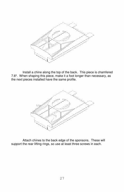
Install a chine along the top of the back. This piece is chamfered7.6º. When shaping this piece, make it a foot longer than necessary, asthe next pieces installed have the same profile.
Attach chines to the back edge of the sponsons. These willsupport the rear lifting rings, so use at least three screws in each.

28
Attach a chine to the rear edge of the deck. This piece shouldbe 1½” wide, twice the width of a normal chine. Half of it will need to bechamfered 7.6º to match the angle of the sponson sides.
Attach chines to the angled sections of the sides of the deck.These too will need to be 1½” wide. The top is chamfered 19.2º wherethe deck meets the sponson top, and the ends are tapered 22.7º.

29
Attach the sponson tops. You’re now done with the hull, exceptfor two parts – the glacis, which will wait until we install the motors, and asmall section of the back, which will wait until we install the rear axle andtensioning mechanism.

30
Part III: Assembling the Suspension
The suspension is by far the most complex part of the tank, andrequires the most precision in its construction if it is to work withouttrouble. The concept is simple – the drive sprocket teeth engage thelinks on the edge of the track and pull it forward. The track pulls on theidler wheel at the back of the tank, and the hull rolls forward on wheelsthat ride along the track. In execution, it is a bit more complex, as thesprocket must fit the track closely, requiring that the track spacing bevery uniform.
Bogies and Road Wheels
The tank rides on six “bogies”, each consisting of four roadwheels, two suspension arms, and a spring. They’re each mounted to a½” steel rod that is attached to the bottom of the tank.
These rods are by far the least realistic part of the tank, butthey’re underneath where you can’t see them. They are ½” steel rods,25½” long. They pass through wood blocks which are screwed throughbottom of the hull into the chines. These blocks are drilled 15/32” andforce-fit onto the rods, so nothing is required to hold the rods place,though if a problem develops, I may go back and either pin them or useepoxy. These blocks can be any size, but the center of the axle shouldbe 1-1/2" from the bottom of the tank.

31
The front axle is 7-7/16" back from the front edge of the bottom;the second and third axles are on a 13" spacing. This should leave justabout 9" from the rear axle to the rear edge of the bottom.
The rods I used came from the local hardware store at about $4or $5 each, but that is the expensive way to buy them. Home Depot hasthem cheaper, and McMaster-Carr sells them even cheaper yet,although shipping is a factor. All were originally 36” long – when you cutthem to 25½”, save the 10½” piece cut off. Later you’ll cut it into three3½“ pieces to use as axles for the road wheels.
Automotive valve springs are ideal for this purpose. I juststopped at my mechanic's shop and asked him if he had any extra valvesprings off an old engine, and he gave them to me free. It doesn’t matterwhat engine they’re from, as long as you get six matched ones. Theyseem too stiff at first, but when you put the weight of the batteries anddriver on them, they’ll won’t seem so stiff.
The suspension arms are designed to be cut from 2x4s. Yourbest bet is to cut a pattern out of a scrap of 1/4" plywood and trace it ontothe 2x4. This will assure that they're all the same, and it goes a lot fasterthan measuring each one individually. You can get a more of them froma smaller piece of wood by alternating their direction, so they fit togetherlike puzzle pieces.

32
Suspension Arm Layout
Cut 12 “arms”, six “male” and six “female” - the “male” pieces willhave a single 13/16” wide tab centered on the thickness, while the“female” pieces will have a matching notch (see the pictures below).
Cutting the Suspension Arms
To help cut these tabs, I made a simple jig to hold thesuspension arms so that I could cut them with by band saw. There are

33
only two critical dimensions to this jig - the angle of the triangular piece is45º, and the distance between the tip of the triangle and the stop is5/16". By placing the arm in this jig upside down, it is held firmly enoughthat you can run it under the band saw to cut the tabs. The end of the jiggets cut when it is used, but this is okay. Just be careful where you putthe nails when you assemble it, so you don't hit them with the blade.
Jig for Cutting the Suspension Arms
Using the Cutting Jig

34
Assemble pairs (one male, one female) with a wooden blockwhere the spring belongs. This block should be the same length as thedesired compressed length of the springs you’re using. The tank weighsaround 250 pounds loaded, but the suspension has a mechanicaladvantage of about 2.2 to 1, so each spring will be under approximately90 pounds of compression. In the case of the automotive springs I used,this force seems to compress them around ½", so the block of wood Iused was 1-3/4", ½” shorter than the 2-1/4" relaxed length of the springs.
Drilling the Suspension Arms
Once you have the pairs of suspension arms assembled aroundthe block, drill the ½” hole through the two arms. This will assure thateverything lines up when assembled. Number the arms so you can keepmatched pairs together.
Install one ½” shaft collar on each of the suspension rods. Theouter face of the shaft collar should be 3" from the side of the hull. Cutthe bottom ½” off of a dozen 35mm film canisters, and nail them to thespring face of the suspension arms with small nails. Insert the spring intothe cups, slide the two suspension arms together, and slide them ontothe suspension rods sticking out from the sides of the tank. You can

35
either thread the ends of the axles and use nylon locking nuts to hold thearms in place, or you can just use shaft collars or snap rings. I did thefirst, but I’d recommend shaft collars.
The road wheels are twenty-four 4½” circles cut from ¾” plywood– pine will NOT do as it will be weak along the grain. I cut a whole pile of4½” squares and then rounded them on the table saw – a dangerouspractice that I do not recommend – and as a result, some have flat spotsbecause I didn’t get them centered exactly. This is okay, in my opinion,as it increases the “rumble factor”, but the tank would probably roll a biteasier if they were all perfectly round. A far more accurate and saferprocedure would be to lay them out with a compass and cut them on theband saw.
Suspension Exploded View
The road wheel axles are made from 3½” lengths of ½” steel rod– the leftover pieces from the suspension rods, cut into thirds. (This willonly give you two-thirds of what you need, however, so you’ll need to cutup another rod.) Chuck each one in a drill press and hold a hacksawagainst them 1/16” from the end, to create a grove for an E-style snapring. I adjusted the table of the drill press to the same height as thedesired groove, and held the blade flat against the table. While the axleis in the drill press, polish it with a piece of fine sand paper.

36
Drill the road wheels 15/32" and force-fit them onto the axles byclamping them in a vice; fit one wheel onto the axle, insert the axle intothe suspension arm, and then fit the other wheel. Adjust by taping gentlywith a hammer, and install the snap rings.
If one of the axles turns out to be too short, you can still use it.Just use a 1” drill bit to carefully counter-bore (drill a shallow depressionaround the bore, a bit like countersinking) into the inner road wheel,effectively making the inner road wheel a bit thinner to give you a bitmore clearance to insert the snap ring. Another alternative is to replacethe inner 3/4" thick wheel with a ½" thick wheel.
I did not use any bushings or bearings on the axles, though itwould have been easy enough to do. McMaster-Carr sells ½” bushingsquite inexpensively. Washers are used between the road wheels andthe suspension arms to keep the wheels from rubbing.
Drive Axles, or Half-Shafts
There are two drive axles, 5/8” rods 14½“ long. I suppose Ishould call them “half-shafts”, as each only reaches the center of thetank, where they are connected together with bearings so they can turnindependently. It is necessary to have two separate axles simply so eachtrack can be driven separately. Otherwise the tank would only go in astraight line!
Drill 1/8” holes through the 3/16” sides of the hull and the ¾”supports inside the hull, at the exact center of the radius of the front – 2-1/8” up from the lower edge of the side (not the bottom, which overlapsthe side), and 2-1/8” back from the front edge. If you used a compass tolay out the side, then this point will already be marked. The ¾” supportsare then removed. Using the drilled holes as guides, the two supportsare then drilled 1-3/8” to accept the bearings. The sides of the hull aredrilled 5/8” to accept the axle.
The two supports are then reattached to the hull, using severalscrews behind the axle, as this is where most of the force on the axle willbe. Two 499502H or similar bearings (preferably with clip rings) areinserted from the inside. It doesn't matter if they fit snugly or a bit lose,as the chain sprockets will hold them in place.

37
Center Assembly Exploded View
The central axle assembly is made up of any piece of pipe 6"long with an inner diameter of equal to the outer diameter of thebearings, 1-3/8" in this case. A chain link fence sleeve works admirably,as there is a small ridge in the center that helps locate the innerbearings, no cutting is required, and it's cheap ($1.29) and readilyavailable at almost any hardware store.
The half-shafts run in two R10-2RS and two 499502H bearingswith clip rings. Any bearing with a 5/8” ID and 1-3/8” OD will do, really.The two bearings without clip rings are inserted into the sleeve, followedby short sections of 1" PVC pipe just long enough to fill the spacebetween the inner and outer bearings and keep them from wanderingaround inside the tube - mine came out to be 2-1/8" long. The two clip-ring bearings are inserted into the ends of the pipe. They will probablynot be tight, but the shaft collars will hold them in place.
The two half-shafts are then run through the bearings in the sideof the hull, through the chain sprockets and shaft collars, and into theassembly, carefully centered so each half-shaft is supported in one of thetwo center bearings. Tighten the shaft collars on the half-shafts againstthe bearings in the center assembly, while the chain sprockets areinstalled against the bearings in the hull to keep them in place as well. Ifthe chain sprockets are held with a set screw, grind a flat spot on theaxle where the screw contacts it, to keep the sprocket from slipping.

38
Drive Axle Center Assembly, Sprockets, and Chains
Note that some of the pictures in this book show a piece of 3/4"pine in the center instead of this assembly - that was the original design.It worked satisfactorily, but this works better.
Track Sprocket
The track sprocket was a challenge. I laid out the sprocket in aCAD program, plotted it, cut it out, and glued it to a piece of ½” plywood.This gave me an accurate pattern to follow while cutting it out on myband saw. If you have access to any kind of CAD software and a goodprinter, I recommend this method. If you don’t, it is not that difficult to layout the pattern by hand.
Start by cutting a circle from ½” plywood 6-9/16” in diameter. Onthis lay out a circle exactly 5-13/16” in diameter; this will be the “pitchcircle”, the effective diameter of the sprocket.
Take a pair of dividers, one set to exactly 1”, and one set toexactly 2”, and mark alternating 1” and 2” steps around the pitchdiameter. You should end in exactly the same place you started – if you

39
don’t, redraw the pitch circle a smidgen (a third of the distance youmissed by) larger or smaller and try again. Keep at it until you’ve got aperfect 12-sided figure with alternating 1” and 2” sides.
Figure 1: Track Sprocket Layout
The points marked on the pitch circle are the centers of the toothbase radii. Draw 3/4” diameter circles around each of these points.Connect the inside edges of pairs on the 1” distance with straight lines -this will match the profile of the track links. Swing a 1-5/8” radius arcaround each center to form the profile of the opposite side of the toothnext to each circle - this traces out the path that the track link takes as itswings away from the sprocket. Examine the picture if I’ve confusedyou.
Take your time and make the sprockets as perfectly as you can.It will pay off with a smooth running track later on. Once you get one

40
sprocket made, use it as a template to make three more. Trace it with avery sharp pencil to minimize error.
Sprocket Assembly Detail
The spacers between the sprocket sides are cut from ¾”plywood using a 2-½” hole-saw, and then drilled out 5/8”. Five arerequired for each side. Once all the pieces are ready, stick a piece of5/8” rod in a vice, and put one sprocket on it, up against the vice. Addfive spacers, each coated with wood glue, and finally another sprocket.Put a spring, one of the same springs that will be later used in thesuspension, over the rod. Compress it and hold it in place with a pair ofvice grips. This will keep pressure on the glue as it sets. Before the gluesets, CAREFULLY align the two sprockets by eye. If you have a piece oftrack ready, lay this over the sprocket to make sure it meshes properly.
Once the glue is dry, drill four ¼" holes, ¾” from the center of thesprocket, all the way through the sprocket assembly. To keep them fromwandering too far off, drill from one side halfway through, and then fromthe other side all the way through. If you don't have a 1/4" drill bit longenough, you can drill each piece separately, before they're gluedtogether. Just be careful to make sure all the holes line up when youassemble it. Pass 5" long ¼” carriage bolts through the four holes, with

41
the head on the side of the sprocket away from the hull, and tighten themdown.
To hold the assembled sprocket onto the drive axle, drill a ¼”hole entirely through the middle spacer, being careful to avoid the screwsand to get the hole centered. Replace the sprocket on the axle andinsert a ¼” bit into the hole and mark the axle for drilling. I left about 1/8”of the drive axle sticking out, but this isn’t necessary. Drill the drive axle¼” on the drill press, being careful to center it exactly.
If you’re not used to drilling steel, then here are some tips:
• use lots of cutting oil (not motor oil or WD-40)• use a new, sharp bit,• use a low drill speed,• drill the hole 1/8” first, then 3/16”, and finally ¼” (this is called
step drilling)• back the bit out frequently to clear the chips• clamp the work firmly so it won’t spin and whack you if the bit
jams• wear safety glasses• don't brush the chips away with your hand - they're sharp!• take your time.
HINT: To clean up magnetic metal chips easily, turn a plasticsandwich bag inside out and drop a magnet into it. Wave it around untilall the chips are stuck to the magnet through the bag. Turn the bag backright side out, and the chips are now in the bag! You can pull the magnetoff and throw the bag away.
Finally, reinstall the sprocket on the rod, line the holes up, anddrive a ¼” steel rod through the whole thing. This is a touchy operation,as if you didn’t get the holes centered correctly, it may be difficult orimpossible to make the holes line up enough to get the pin in. Taperingthe end of the ¼” rod will help. In my case, the holes were ever soslightly off – just enough to make a nice, tight fit so the ¼” rod wouldn’tfall back out.
In the picture above, the ¼” rod is not in place – instead a 3/16”bolt is shown.

42
Rear Axle and Idler Wheels
The rear axle is a 5/8” rod that passes through slots in the side ofthe hull. The slots are necessary to allow the track tension to beadjusted. They need to be as long as the pitch of the track plus thediameter of the axle – in this case, 3-5/8". If you need more adjustmentthan this, you can add or remove a link. The center of the slot is 2-1/8"above the lower edge of the side (not the bottom, which over laps theside). Shaft collars keep the rear axle from moving sideways.
Track Tensioning Mechanism, also showing Battery Tray and Fan
The axle is passed through two 3/4" diameter 4” long eye boltsthat pass through the rear of the tank. Cranking down the nuts on theeye bolts draws the bolts, and the axle, toward the rear. Obviously, theholes for the eye bolts are aligned with the slots, 2-1/8" above the loweredge of the side. Their location in from the outer edge is about 1-½" orso - it doesn't matter much.
The idler wheels are 5” in diameter, and are assembled verysimilarly to the way the drive sprockets were assembled – two outerwheels and a series of inner spacers, held together with glue andscrews. Because it only needs to be as wide as the bells, and not the

43
entire track, only two ½” spacers and one ¾” spacer were used. It is notpinned to the 5/8” axle, but rather left to turn freely. Shaft collars areused to keep it in place.
Track
Building the track is very tedious, but don’t rush it. The moreaccurately you build the tracks, the less trouble you’ll have with themlater. (By the way - they're tracks, not treads.)
The track is made from 3-5/8” wide by ¾” thick lengths of pine – Icut a 2x4 in half lengthwise. Four eight foot lengths are required. Sincethe tracks are going to be beaten up and abused, there is no point inusing nice wood - if you’ve got an old warped 2x4 covered in paint anddirt and nail holes, this is the place to use it.
You might also consider using recycled "plastic lumber", whichwouldn't have a tendency to split. It's more expensive, however.
Cut these into seventy 2¾” x 3-5/8” pieces (“pads”) and seventy1¾” x 3-5/8” pieces. Half of these latter pieces are cut, parallel to thegrain, into quarters 13/16” wide (assuming a 1/8” kerf) to make 140“connectors”. The remaining pieces are cut into 1-5/8” squares to form“bells”.
It is tempting to cut a length of ¾” pine to a width of 1¾”, roundthe edges on a wood shaper, and then cut it into ¾” pieces, as this willproduce connectors with the ends already rounded. However, if this isdone, the grain will be perpendicular to the length of the connector, andmuch weaker. These connectors are already the “weak links” in thetrack.
You will probably want an extra length of track to replace brokenparts in the field. Real Shermans often carried several short sectionsattached to the glacis, sides, or turret.

44
Track Construction
Track Drilling Jig

45
Build a jig to drill 1/8” holes in the sides of the connectors andpads, 3/8” in from the edge and from either surface. It is very importantthat these holes be exactly 2” apart in the pads, and 1” apart in theconnectors, as the track will not mesh with the sprocket if thesedimensions are not strictly followed. The holes must pass entirelythrough the connectors, and at least an inch into the pads. Yes, I knowthis is a total of 560 holes. If you think this part is tedious, you’ll lovewhat comes next!
Sand or otherwise round (I used a disk sander) the ends of eachconnector to a radius of 3/8”. That’s 560 edges. Have fun, and if youuse a sander, wear a dust mask. If you can figure out how to make a jigto do this, go for it – it will result in more accurately shaped links and asmoother running track.
When you’re FINALLY done, you can assemble the tracks. Eachtrack takes 35 pads and 70 connectors. You can use 2” wallboardscrews, but DO NOT screw them all the way in unless you countersinkthe holes in the links, as the trumpet shape of the underside of the headwill split the connector. A 2” screw with a round (flat-backed) head wouldbe better (in fact, I suppose you could even use nails). The finer thethread pitch the better, as the connector will tend to “climb” the threads,moving slightly inward and outward, as the connector turns on the screw.Some wallboard screws have many threads per inch, but they actuallyhave more than one thread, so the pitch is coarser than it appears.
Don’t tighten the screws down, as the connectors must be free tomove. Insert a piece of paper between the connector and the pad to actas a spacer as you assemble it to insure free movement.
Once you’ve got 35 complete links in a row, lay them out in astraight line and look them over. If they aren’t straight, you will find a linkor a pad that is either too short or too long. Replace it.
Once the track looks nice and straight, draw a centerline downthe length of the track, followed by two more lines 13/16” on either sideof it. These lines will guide you as you glue the bells in place.
Install the tracks on the tank. The easiest way is to remove therear idler wheels, and then reinstall them when the track is in place.
Once the track is in place, you can adjust the bogies and the rearidler wheels in or out to line up with the sprockets. With the tank sitting

46
on the tracks, adjust the track tension until the tank rolls freely, but thetop of the track doesn’t hang down and hit the bogies. In theory, the tankshould have track return rollers above each bogie to support the trackacross the top, but I have found that they weren’t necessary.
Tank Cradle and Lifting Rig (optional)
About now you’ll notice that the tank is getting awfully damnedheavy, and it’s big enough to be really awkward to try to lift. You mightconsider building a cradle and lifting rig to make handling it a little easier.
The cradle I built was simply an old microwave stand, whichholds the tank at just the right height to work on, and the wheels on themicrowave stand allow me to roll the tank around easily - once you getthe motors installed, you will find that this is about the only way to movethe tank without the batteries in it!
I screwed a pair of 1½” square strips to the top of the microwavestand, and notched them to accept the axles under the tank, between theblocks that hold them to the bottom of the tank. This holds the tanksecurely, yet leaves the tracks free for adjustment and testing.
To lift the tank up onto the cradle, I installed 3/8” lifting rings inthe front corners of the deck, and the rear corners of the sponson tops.These pass through the plywood and chines, and are bolted underneath.These lifting rings accept s-hooks attached to a 3/8” rope that passesover a pulley attached to a floor joist in my basement.
Do not attempt to lift the tank with the batteries in place! Theyare far too heavy for 3/8” rope and 3/8” lifting rings, and if you drop thetank, the batteries will not only destroy the tank, but probably crack openand spill acid everywhere. Naturally, you must never attempt to lift thetank with a child in it, and never let anyone underneath the tank when itis suspended.
For what it is worth, I have dropped the tank; the rope jammed inthe pulley and then broke. The tank fell a distance of about 30", with atremendous crash, and I was sure it was destroyed. However, only afew of the suspension arms were broken (split along the grain), and wereeasily repaired. The track survived without any damage at all.

47
Part IV: The Turret
The turret was by far the most complex part of the tank todesign. After half a dozen tries, I finally developed a turret that actuallylooked like a turret. It was more complex then I liked, but simpler turretslooked really stupid. This one takes a while to build because of thecurved surfaces, but it looks really sharp.
The upper, lower, front, and the rear surfaces are made of 3/16”plywood – the sides are cardboard, though 1/8" plywood would workbetter. There is a piece of ¾” plywood (pine would work fine too) in theback to hold the bustle in shape, and a pair of ¾” pine (plywood wouldwork fine too) triangles in front to hold the fascia at the right angle (60°).Again, ¾” chines at the joints hold it all together.
If you’re building this as a remote control model, you skip cuttingout the top of the turret.
If you save the piece cut out of the top of the turret, you couldmake a "cap" that fits back in the hole and carries a few extra details, likehatches and antennas.

48
Turret Plans
Exploded View of Turret

49
Turret Rear Layout
Turret Bustle Bottom Layout

50
Bustle Frame Layout (3/4” pine)
Bustle Top Layout

51
Turret Top
Turret Front

52
Turret Base

53
Turret Ring Construction
You should probably start with the turret ring - I started with thefront and gun, and it made gluing the ring a real interesting challenge, asI could not lay it flat.
The turret ring is assembled from two layers of 2” wide strips of1/8” plywood, 44” long, bent to form a circle. Insert one piece into thehole in the turret bottom, and trim it to a tight fit, so the ends touch but donot overlap. Insert the other piece inside the first piece, and trim that to atight fit as well. Remove the inner layer, apply a good layer of wood glueon the inside of the outer layer, and reinsert the inner layer, locating thejoint 180º from the joint in the outer layer. If you have a good, tight fit,you won’t need any c-clamps.
The strips of 1/8” plywood I had available turned out to beseveral inches too short to go all the way around the opening. Ipositioned the gaps in the inner and outer layers opposite each other,and filled them in with additional short pieces. Once the glue has dried,you can glue the ring in place in the turret bottom. Fill any gaps withwood putty.

54
HINT: A cheap and effective wood putty is made by mixing finesawdust with wood glue. Coarse sawdust works too, but has a terriblesurface. Lay on thinly and let it dry before sanding.
Turret Bearings
Make “bearings” out of little plastic wheels, riding on axles madefrom finishing nails. The wheels I used were salvaged from McDonald’sHappy Meal toys, but any small disk will work as long as the axle hole isin the exact center. You’ll need at least three wheels, though the morethe better.
The turret is held to the hull by three pins – I used 3/16” bolts.One is located at the back of the turret in the center, passing through theturret ring below the hull surface. Two more, located near 45° left andright of forward, are mounted on springs so that they can be easilywithdrawn from their holes, allowing the turret to be lifted free of the hull.
The turret front is attached to the base by a pair of triangles, cutfrom 3/4" pine. These are 60º right triangles, the short side of which is2”. They are screwed to the turret front flush with the edges of thesquare hole and the bottom edge. Saw a shallow notch in the

55
hypotenuse of the triangle at the midpoint of the opening to accept afinishing nail that serves an axle for the gun.
Turret Construction
The bustle, or the part of the turret that sticks out toward theback, is supported in the center by a piece of 3/4" pine (I actually usedplywood, it doesn't matter) that holds the three bustle surfaces in place.Be sure to the edges of this piece are perfectly square to the surface.
Once the plywood parts are assembled, the sides are glued on.Simply cut a large rectangle of whatever material you are using, and uselots of duct tape to hold it in place while the glue dries. Start with thebustle and work forward. Once the glue is dry, trim the sides to fit.
I used corrugated cardboard for the sides. I had to slice the innersurface between each corrugation to get it to curve smoothly, but thatdidn’t take long and doesn’t seem to have effected its strength much. Ifilled the edges of the cardboard with wood putty (sawdust and glue) togive in a nice smooth edge.
A better material to use for the sides would be 1/8” plywood,probably the rest of the sheet that provided the parts for the turret ring.

56
Gun Mount Construction
Sheet metal will also work for the sides of the turret, but be sureto turn the edges over so they aren’t sharp. To achieve the properrounded shape of the original Sherman turret (which was cast), papier-mâché could be used.
The Gun
The barrel of the gun is a piece of 1" nominal diameter PVCpipe, 18" long. Later Shermans had the 76mm gun, which had a longerbarrel, so you could use a 30" piece instead.
The gun mount is a piece of 4" diameter PVC drain (DWV) pipe,7" long. Cut this piece as square as possible, as any runout on the endwill cause it to bind against the sides of the hole.
Plug the ends of this piece with circles of plywood cut to fit tightlyand glued in place. Whatever method you use to cut the circles, be surethey are very round, and mark the center accurately.

57
To make sure the barrel went through the exact center of the gunmount, mark the center of one hole on one side of the gun mount,exactly 3-½" from either end, measure the circumference, and divide bytwo. Measure both ways around the mount to minimize any error, andthen mark the center of the hole on the other side.
Drill a hole to match the outside diameter of your PVC barrel.Mine is 1.315" in diameter, and since I didn't have a drill that size, Idrilled it 1-1/4" and opened it up with a carpet knife. You want a fairlytight fit. You can use either PVC cement or epoxy to hold the barrel inplace.
Drive small finishing nails into the centers of the circles at theends of the gun mount to act as axles, and fit them into the notches inthe triangular supports holding the front of the turret, as shown.
Paint
If you’ve made it this far, you’re ready for paint! You can paintyour tank in pretty much any scheme you want, as the Sherman wasused my many armies all over the world for quite a long time, sowhatever color you choose, it probably has a precedent somewhere.
I chose the basic WW II olive drab scheme. I understand thatolive drab is often available in spray cans car parts stores. I was notable to find any, so I used Krylon "Hunter Green" instead.
It took a total of two spray cans of green, three of gray primer,and one of white to do it all. Apply a coat of gray primer to the entiretank, including the tracks, followed by a coat of dark green to the hull andsuspension only, leaving the tracks gray.
Cut a star 6” in diameter in a piece of cardboard – the back of apad of paper works well – and use it as a stencil to spray white stars onthe sides of the turret, the sides of the sponsons, and the glacis. If youwant, you can also get some small stencils and put a number on thesides near the back.
The original Sherman (and I believe all US tanks since) had theinterior painted white. I considered this, but decided that the lightplywood color was close enough.

58
Part V: The Electrical SystemThe tank uses a 24v electrical system instead of a more typical
12v system. By doubling the voltage, the same amount of power can bedelivered to the motors with half the current, keeping the required wiregauge down.
Running 12v Accessories on 24v
However, using a 24v system did make wiring up the rest of it abit complicated, as 12v automotive accessories couldn’t be easily used.There are several ways to use 12v accessories in a 24v system – use abig resistor, use a DC to DC converter, or wire two identical 12vaccessories in series. (You could also tap 12v off one of the batteries,but then the load on the batteries would be unequal.)
Using a big resistor cheap and easy, but rather wasteful. Iadvise against it, but I’ll tell you how it’s done in case you can't avoid it.In a nutshell, you simply calculate the resistance of the load, and thepower dissipated by the load at 12v, and put it in series with a resistorwith the same values. For example, the 12v fan in the batterycompartment of the tank (I guess you could call it a “bilge blower”) drawsone-half amp. Using Ohm’s Law (I=E/R) we can calculate that it’simpedance (effective resistance, in the case of a motor, due to thecounter EMF generated in the armature and the inductance of thewindings) is 24 ohms (12 volts divided by 0.5 amps equals 24 ohms). Tomake the motor run on 12v in a 24v system, we need to put a 24 ohmresistor in series with it. This resistor will need to dissipate six watts ofheat (12 volt drop times 0.5 amps equals 6 watts). That’s a rather largeamount of power to be wasting, but it’s insignificant compared to thepower consumed by the motors, and even the headlights.
You can also wire pairs of identical loads in series. The voltagedrop across two loads in series is equal to the proportion of it’sresistance to the total resistance in the circuit, so if the two loads are ofequal resistance, they’ll each drop half the voltage – 12v in a 24vsystem. The lights on the tank, for example, are pairs of 12v lights wiredin series. This is effectively the same as using a resistor, except that the“resistor” is doing something useful instead of just getting hot.

59
A better way would be to use a DC-to-DC converter, a smallelectronic device that takes in 24v and puts out 12v. This is done withhigh-speed switching transistors and so on, rather than pure resistiveloads, so there is very little loss of power. However, DC-to-DCconverters aren’t all that cheap, though if you have any electronicsexperience, you can build one quite cheaply. There is a schematic for anice-looking one on the web, at http://www.romanblack.com/smps.htm.
Wire
Naturally, the components of the electrical system – wires,relays, switches, etc – must be sized to handle the maximum current themotors will draw.
Wire Gauge Current6 100 amps8 50 amps10 30 amps12 20 amps16 10 amps
The bigger the wire, the less the voltage drop across it, so themore power reaches your motor. The smaller the wire, the greater thevoltage drop, and the more power it will convert into heat. At some point,the wire will become dangerously hot, and can even burst into flame.
You will need about three feet of 6 gauge wire (between thebatteries and the relays), about 20 feet of 8 gauge wire (between therelays and the motors), and all the rest can be done with about fifty feetof 16 gauge wire.
Batteries
The batteries are the second most expensive parts of thisproject. Take good care of them and they’ll outlast the tank and be readyto serve in another project.
The batteries I used are 12v, 75ah deep-cycle marine batteries,the size and shape of a “standard” car battery, wired in series so they actas a single 24v 75ah battery. They weigh 42.5 pounds each – togetherthey weigh as much as the rest of the tank! I bought them from a local

60
car parts store for $40 each plus a $10 core charge (here is your chanceto get rid of those old car batteries you’ve got in the garage). By theway, when the salesman tells you they’re sold fully charged, don’tbelieve him.
DO NOT discharge batteries any more than necessary.Batteries last a finite number of cycles – how many is determined by thedepth of discharge. A battery that dies after 50 full discharges couldeasily last 400 50% discharges, or more. A battery may well last foreverif only exposed to 25% discharges. Marine and deep-cycle batteries aremuch better at withstanding “deep” discharges than are car batteries, buteven they benefit from shallow discharges.
Nor should you leave a battery even partially discharged, as thisencourages the growth of sulfur crystals on the plates, clogging thepores and damaging the battery. Charge them up, and keep themcharged up.
Consider an automatic battery charger. These decrease thecharging current as the battery approaches full charge, and shut offwhen it reaches full charge, preventing overcharging. Overcharging candamage the battery, as well as spewing battery acid all over. Anautomatic battery charger can be put on the battery and then forgotten.They’re not much more expensive than a manual battery charger.
You can estimate the state of charge of a 12v lead-acid batteryby measuring the specific gravity of the electrolyte, or by measuring it’svoltage. The latter is certainly easier, especially with “maintenance-free”and sealed batteries.
State of Charge Specific Gravity Voltage100% 1.265 12.6875% 1.225 12.4550% 1.190 12.2425% 1.155 12.06Dead 1.120 11.89
Consider a minimum voltage cutoff circuit. This will disconnectthe batteries when they reach a preset voltage, preventing accidentalover-discharging.

61
Treat batteries this size with respect. There is a tremendousamount of energy in them, and if it comes out all at once (short circuit),you’ll regret it. I've got burns to prove it! Properly sized fuses are anabsolute requirement.
The batteries fill the engine compartment
The batteries are located side by side in the back, where theoriginal Sherman had the engine. If you build this tank as a remotecontrol toy, move the batteries to the middle of the tank, under the turret.
I turned them so the terminals faced away from each other, tomake it a bit harder to drop a wrench across the terminals and shortthem out. The battery supports are made of 1½” square lengths of pine,cut from 2x4. The top was notched ¼” deep 1¼” wide, leaving a ¼” lip.The bottom ends of the tray were notched ¾” to sit on the chines andattached with screws. The image earlier in this text showing the tracktensioning mechanism also shows one of the battery supports.
DO NOT CHARGE THE BATTERIES IN THE TANK.

62
Motor Selection
You need two worm gear motors, with a bare minimum stalltorque of 30 ft-lbs of torque (each), and a free rpm of 150 rpm. They willprobably be called ¼ hp, and you can expect them to draw 10 ampseach under a normal load, and as much as 30 amps stalled. Try to getright and left motors (mirror images of each other), as this will makeinstallation easier.
HINT: Beware the phenomenon known as “gear-limited”. This issalesman-speak for “we’re too cheap to put decent gears in our motors.”Some gear motors can generate enough torque to shred the gears in thegearboxes, so the maximum torque given for these motors is themaximum that the gearbox can handle, and not the most the motor cangenerate. Any time you load such a motor heavily – like when turning orgoing up a hill – there is a danger that you’ll overload the gearboxes andthey will die a noisy and expensive death. Avoid gear-limited motors likethe absurdities they are.
The first motors I bought came from Surplus Center, a surplusdistributor. I believe they had originally been made by AM Equipment,part number 224-1103. I timed them at 67 RPM with no load, andaccording to AM Equipment, they generated 17 ft-lbs of torque. Theyproved to be adequate for driving the tank straight ahead, but they hadinsufficient power to pirouette, and worse, the were “gear-limited”. If Ihad geared them down sufficiently, say 3 to 1, they probably would haveworked, but the tank would have been very, very slow.
After trying unsuccessfully to locate replacement gears for them,I bought another pair of AM Equipment motors, part number 265-1002,though BotParts.com. Originally designed as heavy-duty electricwheelchair motors, these motors generate 47 ft-lbs of torque and draw43 amps at stall, and turn 82 RPM with no load, according to dataprovided by AM Equipment. Due to wire losses, in practice these motorsdraw somewhat less current and probably generate less torque. Theyhave proven to be quite adequate for my needs. They mount with three6mm screws, and have 12mm shafts.
Installing the Motors
The motors are located at the front of the sponsons, attached to3/4" pine boards that run vertically from the lower side to the main deck.

63
The exact location and dimensions of this piece will depend on themotors you use. Mine are 3-3/4" wide, 3/4" thick, and long enough toreach from the top of the lower chines to the bottom of the deck, wherethey fit into slots in the chine at the front of the main deck. The slots areto keep the motor mounts from twisting under load and loosening thechain.
Because the motors are identical, rather than being mirrorimages of each other, the right motor is mounted almost an inch lowerthan the other, and rotated 15°.
Motor Mount Details.
Chains carry the power to the drive axles. I first used #25 chainand 40 tooth sprockets, but later switched to #35 chain and 15 toothsprockets, as the #25 chain tended to jump off the sprockets under load.#35 chain also has a much higher operating strength (480 lbs versus 140lbs). Use the largest sprockets you can physically fit, as they will resultin lower chain tension and less strain on the motor mounts.
I had difficulty finding a #35 sprocket that would mount on a12mm shaft. (Don't confuse #35 sprockets with #30 sprockets, which Idid find for a 12 mm shaft - the roller diameter is different.) In the end Ihad to use sprockets with a 1/2" bore and install a thin (0.008") metal

64
shims around the shafts to bring them up to the proper size. To attachthem firmly, I drilled a 3/16" hole through the sprockets and the motorshafts and pinned them in place.
To adjust the tension on the chain, I made the motor mountspivot around their lower rear corner, where I attached them to the side ofthe hull with a 3/8" carriage bolt. Tension is provided by a 6" 1/4" boltthat passes through a steel bracket attached to the motor mount by oneof the same 6mm bolts that attaches the motor, and a second identicalbracket bolted to the upper side chine about 10" behind the motor mount.
Motor Mount Tensioner (joystick in background)
I made these brackets, as the only commercial brackets I couldfind appeared to flimsy. I bought a strap of 1/8" thick 3/4" wide steel, andcut it into four 3-1/4" lengths. I drilled these pieces 1/4", 3/8" from theends and centered on the width. Then, using a large vice and ahammer, I bent 3/4" of one end over to form an L shape. The 6" boltpasses through the short end of the L. You can use a carriage bolt if youuse a file to make the hole in the bracket square.

65
Drive Motor Installation, showing motor, mount, 40 tooth sprocket and#25 chain (later replaced with 15 tooth sprocket and #35 chain), and
chain guard. Chain guards are a MUST if this is to be a ride-in toy for achild.
If this is intended as a ride-in toy for a child, you MUST cover thechains with guards. I made guards from 3/16” plywood. One easy wayto make a chain guard is to cut a piece of plywood that follows the pathof the chain but is about 3/8" larger, and edge it with a piece of plasticedge protector, a piece of clear plastic "angle iron" used to protect wallcorners.
To get the plastic edge protector to bend around the sprockets,cut one surface off. It cuts easily with wire cutters, sheet metal shears, acarpet knife, or on the band saw, and with one side removed, it becomesvery flexible. Attach it to the plywood with small nails, bent over on theother side so they don't interfere with the chain.
Small spacer blocks hold the chain guard in place. It shouldn'trub against the chain, as that will cause derailments.

66
Chain Guard
Once you've finished installing the motors, sprockets, chains,and chain guards, you may install the glacis. You can use screws, ofcourse, but you might also use Velcro to make the glacis easilyremovable for adjustments to the chains.
Motor Control
To control the motors, I decided to use relays. They’re simple,cheap, and reliable. Their drawback is that they only provide two states– on and off. I would have preferred to use some kind of proportionalcontrol, but I didn’t want to get into that yet. It should be a simpleprocess to retrofit the tank with PWM motor controllers at some point inthe future.
I used four 24v 30a DPST relays. I bought them from CPISurplus (http://www.cpisurplus.com) for a mere $1.25 each. Using pairsof DPST relays allowed me, in effect, to simulate a pair of DPDT center-off switches, which would allow me not only reverse the motors, but alsostart and stop them without resorting to a separate switch.

67
Relays and Fuse Block
The relays are all mounted in the right rear sponson, next to thebatteries. A four-fuse block also sits back there. The schematic shows50A fuses protecting the motors, but they should be sized to match thestall current of the motor. The fan is on the same circuit as the controlrelays, so that the tank cannot be operated if the fan fuse blows. It isprobably not necessary, but I wanted the fan running at all times whenthe tank is in use.
You'll save a lot of wire if you put the relays on the same side asthe joystick.

68
Schematic
The relays are controlled by a single arcade-style joystickmounted in one of the sponsons – I put in on the left, since my son is alefty, but it doesn’t matter where you put it. I bought this joystick oneBay, but you can also get them directly from X-Arcade (www.x-arcade.com) for a mere $6 plus shipping. This joystick has a really solidfeel to it, much better than the creaking plastic joysticks used for PCcomputer games, but it is strictly binary control – on or off – so it won’t

69
work with any kind of proportional control system. I had to shorten thestick a bit to make it fit in the sponson. I did this by putting the stick inmy drill press and holding a hacksaw blade against it as it turned at lowspeed. I made the notch for the clip-ring the same way.
Joystick Installation
The joystick is mounted at a 45º angle around the vertical axis,so that pushing it forward triggers not just one switch, but two – thistriggers both motors, and the tank moves forward. Pulling it backtriggers the other two switches, which triggers both motors in the otherdirection, and the tank moves backwards. Pushing the stick to one sidetriggers one of the forward switches and one of the reverse switches,causing the tank to pirouette.
The front right switch is hooked to the relay that drives the leftmotor forward, and the front left switch is hooked to the relay that drivesthe right motor forward. This may seem backward, but remember thatthe tank will turn away from the driven track. When backing, however,the tank will turn toward the driven track, so the rear right switch ishooked to the relay that drives the right motor backwards, and the rearleft switch is hooked to the relay that drives the left motor backward.

70
By pushing the stick straight forward, both forward switches areclosed, and both forward relays are energized, causing the tank to moveforward. Pushing the stick right will energize the relays that drive the lefttrack forward, and the right track backward, causing the tank to pirouette.By not pushing the stick in any direction, all the switches are left open, allthe relays remain off, and the tank does not move.
Joystick Detail, showing Stop, Forward, and Right Pirouette positions
The diagrams above show SPST switches, but the X-arcadejoystick I used actually has SPDT switches. The common terminal ofeach switch was connected together and (through a fuse) to the positiveterminal of the battery, and the normally open terminal of each switchwas connected to its associated relay coil. The other terminal of eachrelay coil was connected to the negative terminal of the battery.
The joystick could easily be replaced with a remote controlreceiver. It can also be supplemented with a second remote joystick,connected by a 5-conductor cable, to allow the tank to be operated whilewalking along side it. However, if you do that you’d have to be carefulnot to operate both joysticks at once as that could generate a shortcircuit.
The tank has no brakes – rather, the worm gears in the motorsact as brakes. Most worm gears have the peculiar property of beingnon-reversible, in the sense that you cannot make the input shaft turn byapplying a torque to the output shaft. This is a very effective means ofbraking, as simply removing power from the motors will cause the tank tostop. Best of all, it requires no additional components! Unfortunately, thisalso means that the only way to make the tracks turn is to apply power tothe motors – pushing or pulling will not work. If the tank breaks downand needs to be towed home, the chains must be slipped off thesprockets (so bring a wrench).
71
Battery Compartment Fan
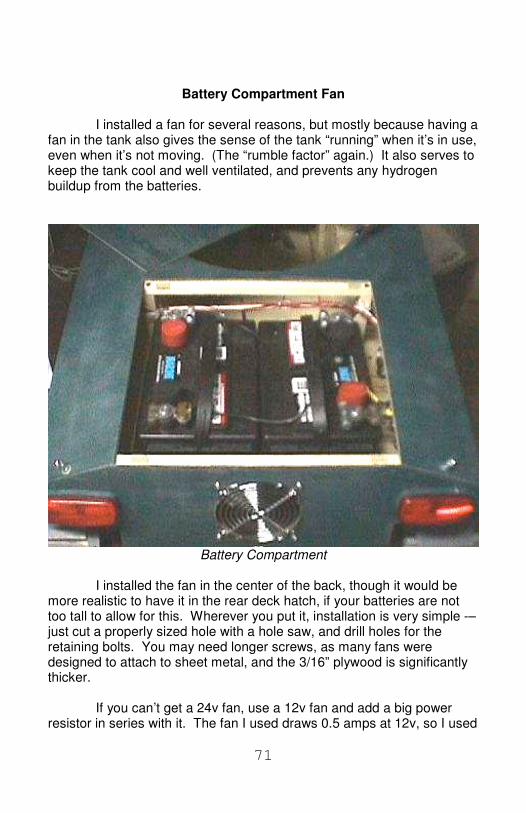
I installed a fan for several reasons, but mostly because having afan in the tank also gives the sense of the tank “running” when it’s in use,even when it’s not moving. (The “rumble factor” again.) It also serves tokeep the tank cool and well ventilated, and prevents any hydrogenbuildup from the batteries.
Battery Compartment
I installed the fan in the center of the back, though it would bemore realistic to have it in the rear deck hatch, if your batteries are nottoo tall to allow for this. Wherever you put it, installation is very simple -–just cut a properly sized hole with a hole saw, and drill holes for theretaining bolts. You may need longer screws, as many fans weredesigned to attach to sheet metal, and the 3/16” plywood is significantlythicker.
If you can’t get a 24v fan, use a 12v fan and add a big powerresistor in series with it. The fan I used draws 0.5 amps at 12v, so I used

72
a 24 ohm resistor (12v divided by 0.5 amps = 24 ohms). Technically, Ionly needed a 6 watt resistor (12v times 0.5 amps = 6 watts), but I useda 55 watt resistor because that is what I had. If you can’t find one withthe right power rating, you can mount a slightly smaller one directlybehind the fan, where the airflow will keep it cool. I found that a 3 wattresistor worked, but got painfully hot.
Once all the wiring is done, you can install the rear deck hatch. Ihold mine in place with a small patch of Velcro in each corner. I put thehook side of the Velcro on the hatch in three corners, and the loop sidein the remaining corner, to make sure the hatch is installed in the properposition, as it is not quite square.
Lights
The lights are purely optional. They are pairs of 12v lights wiredin series. They are all controlled by a single 6-amp switch located in theright sponson of the tank, convenient to where the driver can reach it.
The tail lights are trailer lights I picked up at a RV store for about$4 each, though you can find them much cheaper elsewhere. Any oldlight will do, as long as it has a red lens (and even that is optional, really)and is small enough to fit where you want to put it. The ones I used drawa half an amp at 12v.
The headlights are 50 watt MR-16 bulbs I bought off eBay forunder $2 each. Metal housings are available for MR-16 bulbs, but Ihave not been able to find them retail, only wholesale with hugeminimum order requirements. The part number, QLV-1, seems to bestandard between manufacturers.
Instead, I made my own housings. They’re made out of wood,and I was wary of the effect that the heat of the bulbs would have onthem. I tested them by running the bulbs in these housings for a half anhour on my workbench, and while the wood got warm, it never got toohot to touch. Even so, I’d recommend 20 watt bulbs instead of the 50watt bulbs I used, if only to keep power consumption down – 50 wattbulbs draw just over 4 amps of power at 12v.
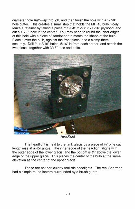
The construction of the headlights is simple. Start with a 2½” x3-3/16” piece of 3/16” plywood, and mark the center of the headlight 1¼”in from one end and from the sides. Using a hole cutter, cut a 2”
73
diameter hole half-way through, and then finish the hole with a 1-7/8”hole cutter. This creates a small step that holds the MR-16 bulb nicely.Make a retainer by taking a piece of 2-3/8” x 2-3/8” x 3/16” plywood, andcut a 1-7/8” hole in the center. You may need to round the inner edgesof this hole with a piece of sandpaper to match the shape of the bulb.Place it over the bulb, against the front piece, and c-clamp themsecurely. Drill four 3/16” holes, 5/16” in from each corner, and attach thetwo pieces together with 3/16” nuts and bolts.
Headlight
The headlight is held to the tank glacis by a piece of ¾” pine cutlengthwise at a 45º angle. The inner edge of the headlight aligns withthe outer edge of the lower glacis, and the bottom is ¾” above the loweredge of the upper glacis. This places the center of the bulb at the sameelevation as the center of the upper glacis.
These are not particularly realistic headlights. The real Shermanhad a simple round lantern surrounded by a brush guard.

74
Headlight Dimensions and Exploded View
I was unable to find sockets for bulbs with this kind of base(known as a G6.3), so I soldered wires directly to the pins. I have sinceheard that “European style” barrier strips will fit. The wires pass througha 3/16” hole in the glacis, located anywhere convenient.
MR-16 bulbs can get VERY HOT, so drill into your youngster thatthey must never touch them, even if they’re off. If you can get largenumbers of white LEDs for a reasonable price, it would be a simple thingto build a pair of LED clusters to use instead of halogen bulbs. They’lldraw significantly less power, and won’t get hot, but they won’t be asbright, either (fairly bright white LED puts out 8000 micro-candela,whereas a 50w MR-16 bulbs put out 160 million mcd).

75
Conclusion And that's it! Take it outside and scare the neighbors! Mount apaintball gun in it and defend the homestead from vandals on Halloween!Build a dozen and stage war games! I know one person who wants toequip one with a shot gun, a TV camera, and R/C controls so he can godeer hunting from the comfort of his living room. (Yes, he's nuts, and no,I don't recommend it.) Personally, I'd rather equip it with a plow andclear my driveway without going outside (the snow plow may hesitate toblock up the end of my driveway if it knew it had a Sherman Tank to dealwith…)
On a slightly more serious note, you might also consider using the trackand suspension design as a platform for a toy bulldozer or excavator.
Please feel free to contact me at [email protected] if you haveany questions or comments (especially photos of your own work) aboutthis project.
I hope you have as much fun building this tank as I had.
- W. E. Johns

76
Appendix I: SourcesMcMaster-Carrhttp://www.mcmaster.com/
The Home Depothttp://www.homedepot.com/
eBayhttp://pages.ebay.com/index.html
[email protected] sells 499503H and R10-2RS bearingson eBay, usually for about $12 for 10 bearings, plus shipping.
AM Equipmenthttp://www.amequipment.com/motor.html
BotPartshttp://www.botparts.com/
Surplus Centerhttp://www.surpluscenter.com/
X-Arcade (joystick)http://xgaming.net/
CPI Surplus (relays)http://www.cpisurplus.com/
Alltronicshttp://www.alltronics.com/

77
Appendix II: GlossaryBustle – the protrusion on the back of the turret. In modern tanks,ammunition is usually stored here. In the Sherman, it was used for aradio.
Bell – The little bump on the inside of the track, on either side of whichpass the road wheels. It serves to keep the wheels “on track”.
Bogie – A set of road wheels (in the case of the Sherman, four) attachedto a common suspension point. [Origin unknown.]
Cannon – a big, mounted gun, usually in the turret. For what it’s worth, agun fires a high velocity projectile on a flat trajectory. A howitzer (fromthe German Haubitze, catapult) fires a slower projectile on a highertrajectory. A mortar fires low velocity projectiles on very high trajectories.Most Shermans were equipped with 75mm or 76mm guns, but somewere equipped with 75mm Howitzers. I saw a photo of a Sherman usedin Korea that appeared to have both a 76mm gun and a 75mm Howitzer,mounted side by side, but I don’t know how common this was (or even ifit was real).
Gear Limited – A phrase used to indicate that the maximum torque agear motor can generate is limited, not by the power of the motor, but bythe strength of the gears in the gearbox. Translates roughly to “do notbuy this motor.”
Gear Motor – A motor with a built-in gearbox. Also Gearmotor, Gear-head Motor, Reduction Motor.
Glacis – the sloped front of the tank. Sloping armor is tougher topenetrate than vertical armor.
Idler – the wheel that takes up the slack in the track. In the Sherman, itis the wheel all the way at the back, and is sometimes called the trailingwheel for this reason.
Mantle – A small shield at the base of the gun, serving to protect the gunmount.
Pirouette – to turn in one place, accomplished by driving the tracks inopposite directions. Requires a lot of torque.

78
Road Wheels – the wheels that roll upon the track. In the case of theSherman, four of them form a bogie. See Bogie.
Sponson – A structure that projects from the side of the hull. In theSherman, the sponsons were the parts of the hull that projects out overthe tracks.
Sprocket – the gear-like wheel having teeth that engage and drive thetracks. Generically, a gear-like wheel having teeth that engage and drivea chain.
Turret – the rotating structure housing the gun. I bet you knew this.
Turret Ring – the circular bearing that attaches the turret to the hullallowing the turret to turn.

79
Appendix III: Motor Calculations
The speed I aimed for was “walking speed”, about 3-4 feet persecond. A little math told me that the RPM of the drive sprocket, with apitch diameter of 5.8”, should be around 120 rpm. How did I do that?The pitch diameter is the effective diameter of the sprocket. 5.8” times pi(3.1415) gives us a circumference of 18.5”, or 1.5 feet (give or take). Tomove 3 feet in one second, the sprocket will have to turn twice persecond, or 120 times in a minute. (Actual top speed for a Sherman tankwas 25 mph, but that was all out, and only on roads.) However, don’tworry too much about the speed, as long as it is close – by choosing thechain sprockets correctly, you can adjust the speed up or down to meetyour requirements (though at the expense of torque).
Torque is a bit harder to calculate. The best way to figure outhow much torque you need is to push the tank and see how hard it is tomove. There are a few ways to do this – perhaps the easiest is to tie arope to the front of the tank, run it under a pulley (this keeps the ropepulling straight forward) and then up over a pulley and back down to aweight. By adjusting the weight, you can find exactly how much force ittakes to barely move the tank. Another method uses a fish scale, and soon. Be creative. Or do as I did and just guess.
Note that a lot of things will effect how much force it takes tomove the tank. Weight, track tension, uphill or downhill, groundcondition, and so on. All this makes any accurate measurementimpossible at worst, and pointless at best. The best you can do is arough ballpark figure. Unless you did something very wrong duringconstruction, you should need around 5 to 10 lbs of force on a smoothhard floor.
Take the required force (in pounds) and divide it by half of thepitch diameter of the drive sprocket in feet (0.25), and that gives youfoot-pounds of torque. 20 ft-lbs of torque is typical. Remember thatthere are two motors, so each motor only needs to supply only half ofthis. But also remember that this is a bare minimum, as you’ll be goingup hills and over bumps, not to mention turning (which requires asurprising amount of torque). If each motor can supply twice the entireamount of torque required, you should be in good shape. Again,remember that by choosing the sprockets carefully, you can increase thetorque available from any particular motor (though at the expense ofspeed).

80
Knowing the torque and speed requirements, we can calculatemechanical power – simply multiply torque in foot-pounds by RPM anddivide by 5252. 20 ft-lbs of torque at 120 rpm is the equivalent of 0.45horsepower.
Unfortunately, knowing the mechanical power required isn’t allthat useful when it comes to shopping for motors, simply because thereare an infinite number of combinations of torque and RPM that willproduce a given amount of power. What you need to look for are freeRPM and stall torque. Free RPM is how fast the motor turns with noload. Stall torque is how much torque the motor generates with the shaftlocked. What we need to do is find a motor that will turn about one thirdfaster than the desired RPM, and generate about four times the requiredtorque at stall.

81
Let me tell you a secret about permanent magnet DC motors.They generate the most torque at stall. As RPM increases, theygenerate less and less torque, until they generate no torque at all at theirfree (maximum) RPM. The relationship between torque and RPM islinear, so if you know stall torque and free RPM, you can calculate torqueat any RPM, and RPM at any torque. This relationship between currentand torque and RPM doesn’t follow exactly when worm gears are used,but it’s reasonably close. Usually.
This graph is based on the data given by the AM Equipment formy motors. Torque is measured in ft-lbs, and power (mechanical) inwatts.
Notice that efficiency peaks at 75% of free RPM – this is prettytypical. The location of this peak is a function of the ratio of stall currentto free current – the lower this ratio, the lower the RPM of the peakefficiency (and the lower the efficiency, too).
The linear nature of the relationship between torque and RPMmeans we can calculate one if we know the other.
Torque = ((free RPM - target RPM) / (free RPM)) * stall torque
RPM = free rpm * (1 - (torque / stall torque))
The first motors I chose generated 18 ft-pounds of torque at stall,and turned 67 RPM without a load. Using these motors as an example, Ican calculate how much torque they generated at 40 RPM:
Torque = ((free RPM - target RPM) / (free RPM)) * stall torque
Torque = ((67 - 40) / (67)) * 18
Torque = 7.25 ft-lbs


![USTA TrafficAnalysisBriefing V7 0 20150530 FINAL[1] · PDF file1."Executive"Summary" ... In2014thethreemajorGulfcarriers" –"Emirates,"Qatar"Airways"and"Etihad" Airways"–"carried"some"4.3"million"passengers"intoandout"of"the](https://static.fdocuments.us/doc/165x107/5aa125967f8b9a46238b5bf2/usta-trafficanalysisbriefing-v7-0-20150530-final1-in2014thethreemajorgulfcarriers.jpg)