Build Your Own Clone Tweed Royal Kit Instructions · 2 - Circuit board standoffs w/matching screws...
158
1 Build Your Own Clone Tweed Royal Kit Instructions (revision 1.0.2) WARNING!!! HIGH VOLTAGE!!!! Tube amplifiers contain high voltage that can cause injury and even death. Please use extreme caution and common sense when building this kit. Do not attempt to do anything to your amp while it is plugged in other than take voltage readings as necessary or actually playing an instrument through it as it was intended. Don't just turn the power off!!! Always unplug the power cord from the socket before working on your amp!!! The mains supply can still electrocute you AND the power filter capacitors can still retain a charge powerful enough to kill you. Always unplug the power cord from the socket before working on your amp.
Transcript of Build Your Own Clone Tweed Royal Kit Instructions · 2 - Circuit board standoffs w/matching screws...

1
Build Your Own Clone Tweed Royal
Kit Instructions (revision 1.0.2)
WARNING!!! HIGH VOLTAGE!!!! Tube amplifiers contain high voltage that can cause injury and even death. Please use extreme caution and common sense when building this kit. Do not attempt to do anything to your amp while it is plugged in other than take voltage readings as necessary or actually playing an instrument through it as it was intended. Don't just turn the power off!!! Always unplug the power cord from the socket before working on your amp!!! The mains supply can still electrocute you AND the power filter capacitors can still retain a charge powerful enough to kill you. Always unplug the power cord from the socket before working on your amp.

2
DISCLAIMER Build at your own risk!!! BYOC, Inc. is not liable or responsible for any damages, injuries, or deaths that may incur from or while building this kit. It is your own responsibility to follow proper safety precautions. Never attempt to build, modify, repair, or perform any sort of maintenance on your amplifier while the power cord is plugged into an AC power source. This kit contains only the amplifier chassis. It is intended to be housed in a non-conductive, electrically insulated cabinet or enclosure. This kit does not come with any such cabinet or enclosure and is not intended to be used without one. It is your responsibility to house this amplifier kit in a proper cabinet or enclosure before attempting to use it. Warranty: BYOC, Inc. guarantees that your kit will be complete and that all parts and components will arrive as described, functioning and free of defect. Soldering, clipping, cutting, stripping, or using any of the components in anyway voids this guarantee. BYOC, Inc. guarantees that the instructions for your kit will be free of any majors errors that would cause you to permanently damage any components in your kit, but does not guarantee that the instructions will be free of typos or minor errors. BYOC, Inc. does not warranty the completed kit as a whole functioning unit, nor do we warranty any of the individual parts once they have been used. If you have a component that is used, but feel it was defective prior to you using it, we reserve the right to determine whether or not the component was faulty upon arrival. Please direct all warranty issues to: [email protected] This would include any missing parts issues. Return: BYOC, Inc. accepts returns and exchanges on all products for any reason, as long as they are unused. We do not accept partial kit returns. Returns and exchanges are for the full purchase price less the cost of shipping and/or any promotional pricing. Return shipping is the customer’s responsibility. This responsibility not only includes the cost of shipping, but accountability of deliver as well. Please contact [email protected] to receive a return authorization before mailing. Tech Support: BYOC, Inc. makes no promises or guarantees that you will successfully complete your kit in a satisfactory manor. Nor does BYOC, Inc. promise or guarantee that you will receive any technical support. Purchasing a product from BYOC, Inc. does not entitle you to any amount of technical support. BYOC, Inc. does not promise or guarantee that any technical support you may receive will be able

3
to resolve any or all issues you may be experiencing. That being said, we will do our best to help you as much as we can. Our philosophy at BYOC is that we will help you only as much as you are willing to help yourself. We have a wonderful and friendly DIY discussion forum with an entire section devoted to the technical support and modifications of BYOC kits. www.buildyourownclone.com/board When posting a tech support thread on the BYOC forum, please post it in the correct lounge, and please title your thread appropriately. If everyone titles their threads “HELP!”, then it makes it impossible for the people who are helping you to keep track of your progress. A very brief description of your specific problem will do. It will also make it easier to see if someone else is having or has had the same problem as you. The question you are about to ask may already be answered. Here is a list of things that you should include in the body of your tech support thread: 1. A detailed explanation of what the problem is. (not just, “It doesn’t work, help”) 2. Photo that clearly shows your circuit board. 3. Photo that clearly shows the tube-side of inside of the chassis. 4. Photo that clearly shows the inside of the front of the chassis. 5. Photo that clearly shows your wiring going from the circuit board to the pots and any other switches (only if your kit has non-PC mounted pots and switches). 6. Does the indicator light come on? Also, please only post photos that are in focus. You're only wasting both parties' time if you post out of focus, low-resolution photos from your cell phone.
Credits: Written by: J. O’Mealey & K. Vonderhulls Artwork by: J. O’Mealey & K. Vonderhulls Edited by: R. Matthews & K. Vonderhulls Revision Notes: Rev 1.0.1 current: typos, artwork, and editing errors from 1.0 corrected. Rev 1.0.2 current: Changed orange cloth wire to blue cloth wire. Copyrights: All material in this document is copyrighted 2012 by BYOC, Inc.

4
TWEED ROYAL KIT
INSTRUCTION INDEX
Parts Checklist………………………………..............…….....page 5 - 8 Populating the Circuit Board (top side)...………...................page 9 – 25 Populating the Circuit Board (under side)………………….page 26 - 49 Chassis Build Up………………………………………….…..page 50 - 93 Adding the Circuit Board........................….............................page 94 - 118 Wiring the S.E./standby/P.P. Switch…....................................page 119 – 132 Heater Wiring………………………………………………….page 133 - 141 Finishing Up……………………………………………….…..page 142 – 144 Turning Your Amp on for the First Time…………………..page 145 – 149 Operating Overview…………………………………………..page 150 - 152 Diagrams and Schematic……………………………………..page 153 - 157

5
Parts Checklist for Tweed Royal Kit Resistors: 1/2watt carbon composition: 1 – 820 ohm (gray/red/brown/gold) *this is an extra part for modification 5 - 1k5 (brown/green/red/gold) *there is one extra for modification 1 – 2k2 (red/red/red/gold) 1 - 22k (red/red/orange/gold) 2 - 56k (green/blue/orange/gold) 4 - 68k (blue/gray/orange/gold) 3 - 100k (brown/black/yellow/gold) 2 - 220k (red/red/yellow/gold) 3 - 1M (brown/black/green/gold) 2watt metal oxide: 2 – 470Ω (yellow/purple/brown/gold or it will just say “470”) *these are extras for modification 1 – 4k7 (yellow/purple/red/gold or it will just say “4k7”) 1 - 22k (red/red/orange/gold or it will just say “22k”) 5watt wire wound: 2 - 470ohm(large white block says “470” on it) Capacitors: 1 – 470pf ceramic disc or silver mica 1 – 0.0047uf axial leaded film 1 - .022uf axial leaded film
6
4 - .1uf axial leaded film 3 - 16uf/475v axial leaded aluminum electrolytic 3 - 25uf/25v axial leaded aluminum electrolytic
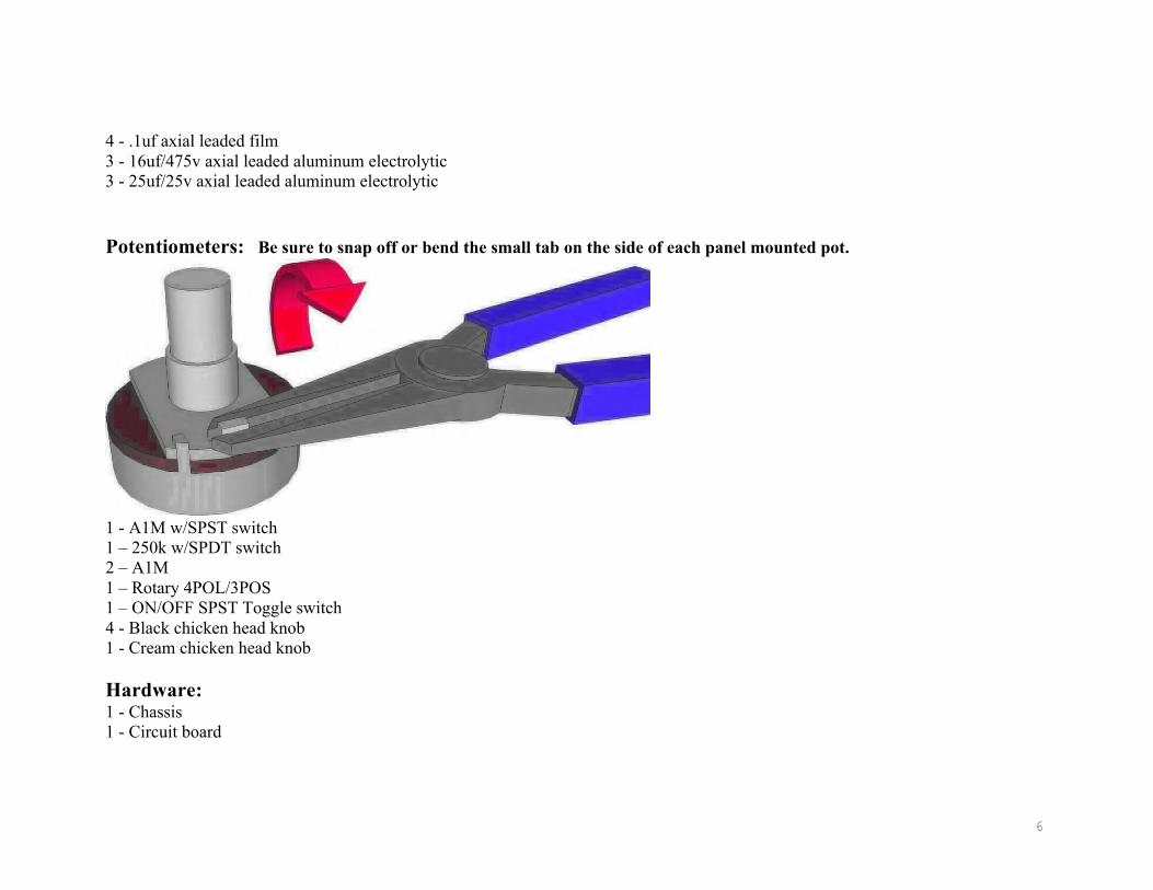
Potentiometers: Be sure to snap off or bend the small tab on the side of each panel mounted pot.
1 - A1M w/SPST switch 1 – 250k w/SPDT switch 2 – A1M 1 – Rotary 4POL/3POS 1 – ON/OFF SPST Toggle switch 4 - Black chicken head knob 1 - Cream chicken head knob Hardware: 1 - Chassis 1 - Circuit board

7
2 - Circuit board standoffs w/matching screws and nuts(M3 size thread) 3 - 8 pin tube sockets w/retainer 2 - 9 pin tube socket w/shield 1 - 1/4” mono w/ nut, flat washer and lock washer 4 - 1/4” mono shorting jacks (switchcraft 12A) w/ nut, flat washer and lock washer 1 - Lamp (bayonet style #47 6.3v) 1 - Lamp holder 1 - Lamp jewel 1 - 6' 3-conductor power cord 1 - Power cord socket 1 - Panel mounted fuse holder 1 - Fuse (3AG 2amp slow-blow) 3 - Rubber Grommets 6 - #4 screw 6 - #4 nut 6 - #4 split ring lock washer 10 - 6/32 x 3/8” screw 10 - 6/32 nut 10 - #6 internal lock washer 2 - Wire nuts 2 - #8 Internal lock washer/Solder terminals 4 - #8 nuts 2 - #8 internal lock washers Wire: NOTE: If your kit comes with push-back cloth wire, you do not need to strip the wire prior to soldering. Ignore the directions when they tell you to strip the wire. Just simply cut the wire to length and then slide the cover back to reveal enough conductor to make your solder connection. After soldering, push the cover back into place. We try to supply push-back wire whenever possible, but supplies at this time are sporadic. You can tell push-back cloth covered wire from regular cloth covered wire because the regular wire will still have PVC insulation under the cloth cover. Push-back wire will always have either solid core conductor or stranded conductor that is so thoroughly tinned that it can appear solid, and it will never have an inner PVC coating.

8
4’ – Green 18AWG or 22AWG 4' - White 20AWG 1' - Black 20AWG 4' - Yellow 20AWG 4' - Brown 20AWG 1' - Red 20AWG 6” – Blue 20AWG 1' - Bare Bus
Tubes (optional): 2 - 12AX7/ECC83 (JJ/Tesla) 2 - 6V6 (JJ/Tesla) 1 - 5Y3 (JJ/Tesla) Transformers: 1 – BYOC-TRPT 1 – BYOC-TROT1 1 – BYOC-TROT2

9
Populating the Circuit Board (top side)
A note before you get started: Follow the order of these instructions. Some of the components need to be ”layered” in a certain order. It will make it much easier when you get to the underside of the
circuit board.
Step 1 - Add the brass standoffs. Do not solder anything yet.

10
Step 2: Add the bare bus wire. Do not solder anything yet.

11
Step 3: Add the 25uf capacitor. The capacitor is polarized. It is EXTREMELY important that you orient these correctly. The positive end with be labeled with a “+” symbol. The positive end will also have an indentation around it. Again, do not solder anything yet. Add the 470Ω resistor to the same terminal lugs as the 25uf cap.

12
Step 4: Next, place the 2watt 4.7k and 22k resistors as shown. Install the three 16uf capacitors. Again, the capacitors are polarized. It is EXTREMELY important that you orient these correctly. The positive end with be labeled with a “+” symbol. The positive end will also have an indentation around it and should be installed with
the resistors.

13
Step 5: Cut a 2.5” piece of the black 22 gauge wire, strip an 1/8” of cover off each end. Place one end into terminal end with the 16uf cap, as shown in photo above. Next, cut a 4” piece of both brown wire and white wire. Strip a 1/8” of cover off each end of both wires. Insert the white wire into the terminal lug with the 25uf cap/470Ω resistor. Insert the brown wire into the terminal lug where the 4.7k/22k resistors & 16uf cap are installed. It may be necessary to curve the brown wire end and hook onto side of the terminal lug should it not fit into it. Solder points highlighted with green arrows; do not solder points highlighted with red arrows.

14
Step 6: Install the 1.5k, 56k, and 1M resistors as shown.

15
Step 7: Install the first 0.1uf capacitor and the two 220k resistors as shown above.

16
Step 8: Cut a 2.5” piece of the yellow 20 gauge wire, strip an 1/8” of cover off both end, and insert one end into the terminal post with the 1M resistor. Then, cut a 3” piece of the white 22 gauge wire, strip 1/8” off each end, and insert one
end into the terminal post with 1.5k resistor & 0.1uf cap. Solder points highlighted by green arrows; do not solder points highlighted by red arrows, as shown in photo below.

17
Step 9: Install the second 0.1uf capacitor, the 0.022uf capacitor, and the 56k, and 100k resistors as shown.

18
Step 10: Cut a 2.5” piece of the yellow wire, strip an 1/8” of cover off both end, and insert one end into the terminal post with the 100k resistor & 0.022 cap. Then, cut a 3” piece of the brown wire, strip 1/8” off each end, and insert one end into
the terminal post with 56k resistor & 0.1uf cap. Solder points highlighted by green arrows; do not solder points highlighted by red arrows, as shown in photo above.

19
Step 11: Add the 1.5k resistor and the third 0.1uf capacitor as shown

20
Step 12: Next, add two of the 68k and two 100k resistors, as shown.

21
Step 13: Install the fourth 0.1uf capacitor as shown.

22
tep 14: Cut three 3.5” pieces of brown wire, two 3.5” pieces of white wire, two pieces of 3.5” yellow wire, and a 3.5” piece of black wire. Strip 1/8” of cover off the ends of all wire. From left to right, along the bottom row of turret lugs in the diagram above, insert
one end of brown wire into the 1.5k lug, one end of yellow wire into the .1uF/100k lug, and one end of white wire into the other 00k/.1uF lug. From left to right, along the top row of turret lugs in the diagram above, insert one end of black wire into the 1.5k lug, ne end of brown wire into the .1uF lug, one end of white wire into the 68k lug, one end of yellow wire into the next 68k lug, and one nd of brown wire into the other .1uF lug. Solder where highlighted by the green arrows. Do not solder where highlighted by the red
arrows.

23
Step 13: Install two 68k resistors as shown. Then, install the 2k2 resistor and the 25uf capacitor into the same terminal post, as
shown. *The 2.2k resistor can be replaced with a 1.5k for more gain or an 820 ohm for even more gain. A 1.5k resistor would be more the “original” specs, but the 2.2k will give you a slightly greater range of clean tones. This amp has a lot of gain on tap. We highly recommend sticking with the 2.2k.

24
Step 16: Cut two 2.5” pieces of white wire. Strip a 1/8” of cover off ends. Insert the one wire into the terminal lug with the 68k resistor, as shown above. Insert the second wire into the terminal lug with the 1.5k resistor & 25uf cap. Next, cut a 2.5” piece of yellow wire, stripping a 1/8” of cover off each end. Insert wire into terminal lug with 68k resistor, as shown above. Then, cut a 2.5” piece of black wire and strip a 1/8” of cover off both ends. Insert wire into terminal lug with 1.5k resistor &
25uf cap, as shown above. Solder where highlighted by green arrows, do not solder where highlighted by red arrows.

25
By now, your board should look like photo above.

26
Circuit Board (underside)
Step 1: Cut a 1 &7/8” piece of black wire and strip a 1/8” of cover off each end. Install on the underside of the board as shown above by the black dashed line, from the terminal lug with your base wire & 16uf cap to the post where both 220k resistors are installed. See below photo; solder where highlighted by green arrows. Ensure the components installed on the topside of these
lugs are securely soldered in place as well.

27
28
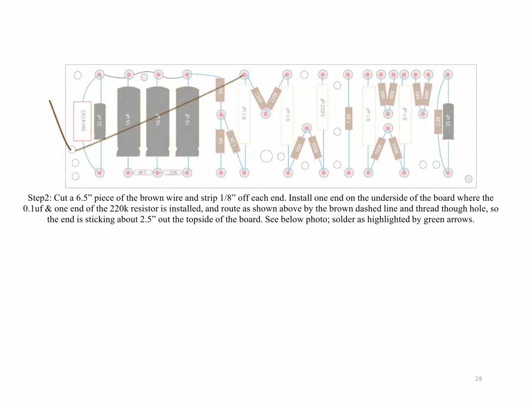
Step2: Cut a 6.5” piece of the brown wire and strip 1/8” off each end. Install one end on the underside of the board where the
0.1uf & one end of the 220k resistor is installed, and route as shown above by the brown dashed line and thread though hole, so the end is sticking about 2.5” out the topside of the board. See below photo; solder as highlighted by green arrows.

29

30
Step 3: Cut a 4.5” piece of red wire. Strip a1/8” of cover off both ends. Install one end on the underside of the board at the terminal where the 16uf & 2watt/4.7k resistor are installed, and route through hole in board so the wire is sticking out the
topside, as you did with the brown wire in the last step. See below photo; solder as highlighted by green arrows.

31

Step 4: Cut a 2.5” piece of red wire and strip an 1/8” of cover off each end. Insert on the underside of the board and route as
shown above by the red dashed line. Solder where highlighted by the green arrows; do not solder yet where highlighted by the red arrows. See photo below.
32

33

34
Step 5: Cut a 6.25” piece of the white wire (shown above in blue) and strip a 1/8” of cover off each end. Insert into the underside of the board, threading it through the holes in the board, so the ends come up through the topside, as shown above. This wire does
not get soldered at all, simply threaded through the holes. See photo below.

35

36
Step 6: Cut a 2.25” piece of the red wire and strip a 1/8” of cover off each end. Insert into the underside of the board and route as
shown above by the red dashed line. Solder as highlighted by the green arrows. See photo below.

37
38
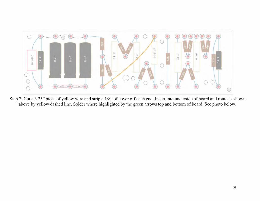
Step 7: Cut a 3.25” piece of yellow wire and strip a 1/8” of cover off each end. Insert into underside of board and route as shown
above by yellow dashed line. Solder where highlighted by the green arrows top and bottom of board. See photo below.

39

40
Step 8: Cut a 8.75” piece of yellow wire and strip a 1/8” of cover off both ends. Install on underside of board with one end at the 0.1uf cap, and route through hole in board, so the wire is sticking out of the topside of the board, as shown above by the yellow
dashed line. Solder where highlighted by the green arrows top and bottom of board. See photo below.

41

42
Step 9: Cut a 3” piece of brown wire and strip a 1/8” of cover off both ends. Insert into the underside of board with one end inserted at the point with 68k resistors and the other end routed through the hole to the topside of the board, as shown above by
the brown dashed line. Solder where highlighted by the green arrows. See photo below.

43

Step10: Cut a 2.75” piece of yellow wire and strip a 1/8” of cover off each end. Install on underside of board, inserting one end of the wire into the point with the other two 68k resistors, and route through hole to topside of board, as shown above by the
yellow dashed line. Solder where highlighted by green arrows. See photo below.
44

45
46
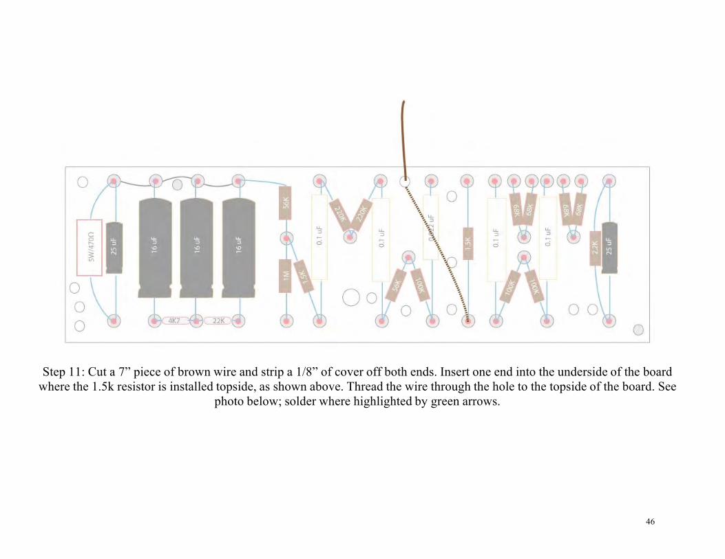
Step 11: Cut a 7” piece of brown wire and strip a 1/8” of cover off both ends. Insert one end into the underside of the board where the 1.5k resistor is installed topside, as shown above. Thread the wire through the hole to the topside of the board. See
photo below; solder where highlighted by green arrows.

47

48
Step 12: Cut a 5.5” piece of white wire and strip a 1/8” of cover off both ends. Insert into underside of the board where the 470Ω resistor & 25uf cap are installed on top, as shown above. Thread wire through hole to topside of board. See photo below; solder
where highlighted by green arrows.

49
Now that you’ve installed all the under board wiring, flip the circuit board right side up and solder all the turret lugs that have
not been soldered yet.

50
Chassis Build Up
Step 1: Install the three rubber grommets into the holes in the chassis.
51
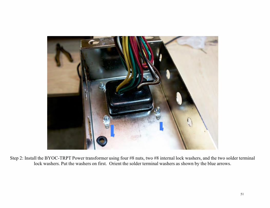
Step 2: Install the BYOC-TRPT Power transformer using four #8 nuts, two #8 internal lock washers, and the two solder terminal lock washers. Put the washers on first. Orient the solder terminal washers as shown by the blue arrows.
52
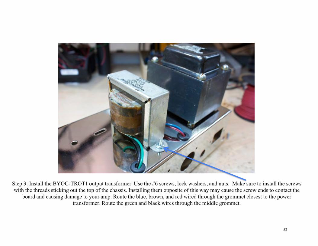
Step 3: Install the BYOC-TROT1 output transformer. Use the #6 screws, lock washers, and nuts. Make sure to install the screws with the threads sticking out the top of the chassis. Installing them opposite of this way may cause the screw ends to contact the
board and causing damage to your amp. Route the blue, brown, and red wired through the grommet closest to the power transformer. Route the green and black wires through the middle grommet.

53
Step 4: Install the BYOC-TROT2 output transformer. Again, use the #6 hardware, and make sure to install the screws with the threads sticking out the top of the chassis. Installing them opposite of this way may cause the screw ends to contact the board
and causing damage to your amp. Route the blue and orange wires through the middle grommet. Route the green and black wires through the grommet farthest away from the power transformer.

54
Step 5: Install the power cord strain relief receptacle. Use the #4 screws, split lock washers, and nuts.

55
Step 6: Install the fuse holder.

56
Step 7: Install the Power On/Off switch.

57
Step 8: Install the power indicator lamp holder. Note; it is not necessary to install the lens jewel cover at this time.
58
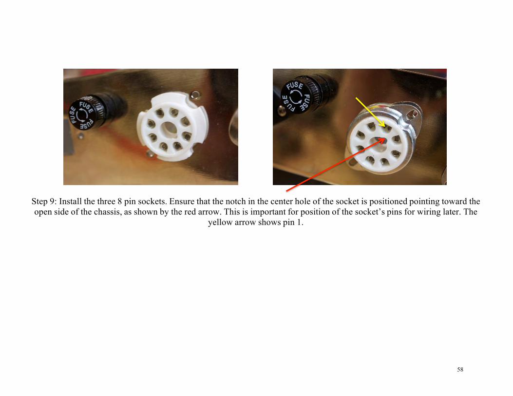
Step 9: Install the three 8 pin sockets. Ensure that the notch in the center hole of the socket is positioned pointing toward the open side of the chassis, as shown by the red arrow. This is important for position of the socket’s pins for wiring later. The
yellow arrow shows pin 1.

59
Then, install the octal tube retainer and mount to chassis with #6 screws, lock washers, and nuts. The final install for the three sockets will look like photo below.

60
Step 10: Install the Rotary 4POL/3POS switch as shown above. Note: The rotary switch shown in this picture has SOLDER terminals. Your kit may have PC terminals.
61
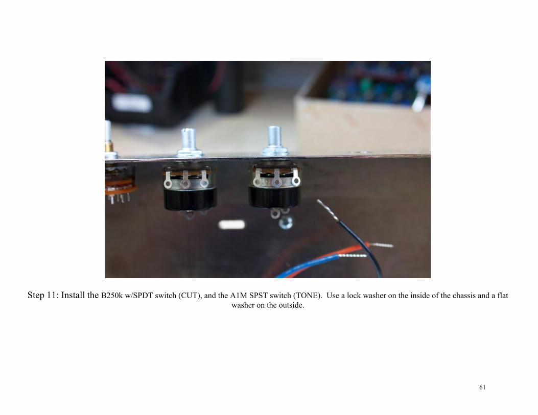
Step 11: Install the B250k w/SPDT switch (CUT), and the A1M SPST switch (TONE). Use a lock washer on the inside of the chassis and a flat
washer on the outside.
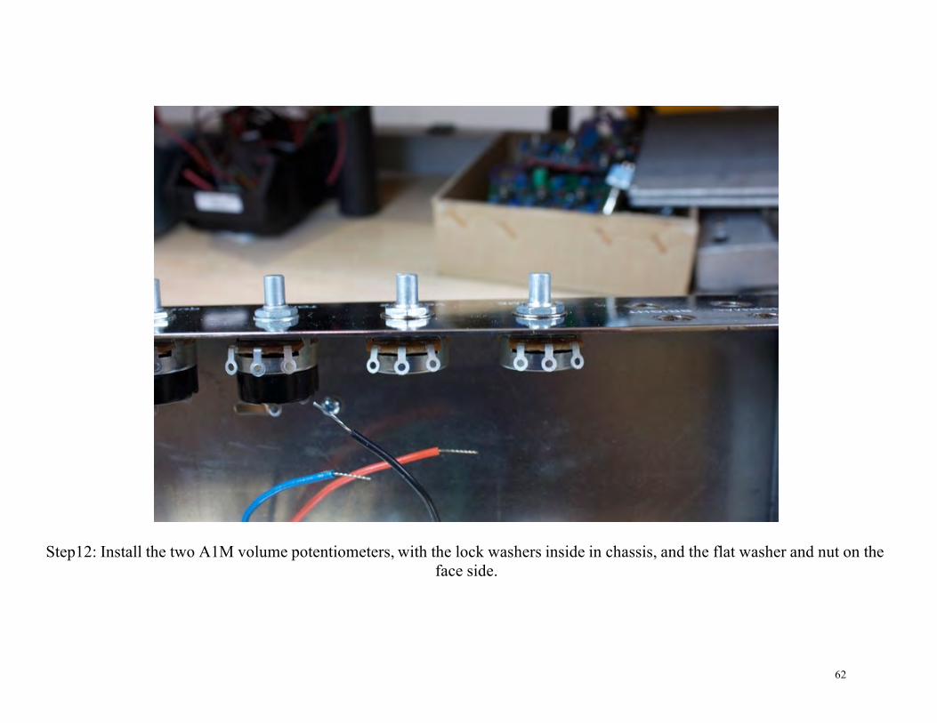
62
Step12: Install the two A1M volume potentiometers, with the lock washers inside in chassis, and the flat washer and nut on the face side.

63
Step 13: Install the four ¼” stereo shorting jacks, with lock washers inside the chassis, and flat washer and nuts on face side. Position the jacks as shown above, so that the middle solder terminals of the jacks on the bottom are pointing to 12 o’clock and
the middle solder terminals of the jacks on the top are pointing to 3 o’clock.

64
Step 14: Install the two 9 pin preamp sockets with #4 screws, lock washers, and nuts. Ensure you position them as shown
above. This will be important for wiring the socket later. Pin 1 is highlighted by the yellow.

65
Step 15: Install the Speaker jack as shown below. Make sure this is the non-shorting mono jack. Place the lock washer on the inside of the chassis, the flat washer and nut on the outside. Be sure to turn the jack so that the sleeve solder terminal is
pointing up and out of the chassis when you mount the jack to the chassis. This will be important later on. The tip prong will short out on one of the turret lugs of the circuit board is you do not orient the jack this way.

66
Wiring
Step 1: Connect both of the green output transformer wires to the tip of the speaker out jack, but do not solder yet. Another wire needs to connect to this terminal as well.

67

68
Step 2: Take a piece of the excess green wire you cut off the transformers in the last step. Connect one end to the TIP of the OUT JACK along with the other green wires from the output transformers. You can now solder all 3 wires at the TIP of the
OUT JACK. The other end of this green wire will connect to lug 1 of the CUT pot. You want to make this connection as short as possible, but at the same time you need to keep in mind that the circuit board will be going on top of this wire, so you need
to allow enough length so that you can route this wire under the circuit board. The circuit board is shown in the diagram above, but it has not been installed in the chassis yet.

69

70
Step 3: Connect the high voltage center tap wire (red/yellow striped) and heater center tap wire (green/yellow striped) to the solder terminal lock washer closest to the fuse holder, but do not solder yet. There is another wire that needs to be added to it
still.

71

72
Step 4: Use a piece of green wire that you cut off of the output transformers to connect the EARTH terminal of the power cord socket to the same solder terminal lock washer. Solder at the green arrows. Keep in mind that the lock washer is connected to the chassis. The chassis will act as a huge heat sink, so this solder joint will take a lot of heat and you will need to hold your
solder iron to the terminal for a long time to make a good solder joint. Make sure all 3 wires are properly soldered.

73

74
Step 5: Install a 1.5k resistor into each of the 6V6 sockets. MAKE SURE YOU DO NOT ADD A RESISTOR TO THE 5Y3 RECTIFIER SOCKET!!!!! Install the resistor so that it jumpers from terminal 5 to terminal 6. Solder the connection at
terminal 5. Do not solder at terminal 6.
TIP: Also take a look at the entire wiring diagram to get a better idea of which tube sockets are being used in this step.

75
Step 6: Connect the blue wires from both output transformers to terminal 3 of the 6V6 socket shown in the diagram above.
TIP: Take a look at the entire wiring diagram to get a better idea of which socket is being used in this step.

76

77
Step 7: Connect the black wires from both output transformers to the SLEEVE terminal of the OUTPUT JACK.

78
Step 8: Cut a 3.5” piece of Blue (previously orange) wire and strip ¼” of cover of both ends. Take the orange wire from TRPT1 output transformer and the piece of wire you just cut. Connect them together with one of the wire nuts, as shown above.
Do not solder this wire into the Rotary switch yet. We will cover the wiring of this switch in the next chapter.

79
Step 9: Connect the solid red wires from the power transformer to terminals 4 and 6 of the rectifier tube socket. It does not
matter which red wire goes to which terminal.

80
Step 10: Connect the solid yellow wires from the power transformer to terminals 2 and 8 of the rectifier socket. It does not matter which yellow wire goes to which terminal. Solder at terminal 2, but do not solder terminal 8 yet. Another wire will be
connected at terminal 8 in a later step.

81
Step 11: Install the 0.0047uf capacitor into lug 1 of both the TONE pot and Channel 2 VOLUME potentiometer. Then, take a 3.5” piece of bare bus wire and create a jumper from lug 1 of both VOLUME 1 & 2 potentiometers, as shown above. Solder
where highlighted by green arrows; do not solder where highlighted by red arrows. You will also need to solder the jumper to the back of both VOLUME potentiometers for grounding. See below photo.
TIP: The backs of the potentiometers are usually covered with a material that prevents solder from adhering. Before you solder the bare bus wire, use a file, some steel wool, a brillo pad, sand paper, emery cloth, or some sort of abrasive to score the
back of the pots were you plan to solder. This will make it much easier for the solder to stick to the pot. Also keep in mind that this connection is “heat sinked” by the chassis and will require more time and heat that most other solder joints, so make
sure you hold your iron to this joint long enough to make a good solder joint.

82

83
Step 12: Connect one terminal of the SPST switch attached to the TONE pot to lug 3 of VOLUME pot #2. Connect lug 3 of VOLUME pot #2 to lug 3 of VOLUME pot #1. Solder the switch terminal and lug 3 of VOLUME pot #2, but do not solder
lug 3 of VOLUME pot #1 yet.

84

85
Step 13: Install the 470 pF capacitor into lug 3 of the TONE pot and lug 2 of VOLUME pot #2, as shown above. Solder where highlighted by green arrows.

86

87
Step 14: Connect the solid green heater wires from the power transformer to the solder terminals of the lamp. Each solder terminal on the lamp will have two holes. Be sure not to get solder in the unused holes. You will need to connect wires in
these holes later in the build.

88

89
Step 15: EXTREMELY IMPORTANT STEP!!!! If this step is not 100% clear to you, please stop what you are doing, and contact BYOC to have this step explained to you in greater detail.
You will need to select your AC mains power supply voltage. Are you going to be using 120VAC (North America and most of Asia) or are you going to be using 240VAC (EU, UK, Australia)? The wires in the diagram above are shown in pink but
represents the brown and white power transformer wires.
120V: Connect the BROWN wire to the fuse holder. Cap off the WHITE wire with a wire nut. 240V: Connect the WHITE wire to the fuse holder. Cap off the BROWN wire with a wire nut.

90
Step 16: Use the excess brown wire from Step 15 (or white if building for 240V). Connect the “N” terminal of the power cord socket to one solder terminal of the power toggle switch. Connect the other solder terminal of power toggle switch to the other
open terminal of the fuse holder. Also, connect the black wire from the power transformer to the “L” terminal of the power cord socket.

91

92
Step 17: Use a piece of brown wire and jumper terminals 4 of both 6V6 sockets. Solder the terminal of the socket closer to the power transformer. Do not solder the terminal of the other socket yet. There will be another wire added to this terminal in a
later step. Take a look at the entire wiring diagram to make sure you are connecting the correct sockets.

93
Step 18: Connect the brown wire from BYOT-TROT1 to terminal 3 of the 6V6 socket closest to the power transformer. Take a
look at the entire wiring diagram to make sure you are connecting to the correct socket.

94
Adding the Circuit Board

95
Carefully turn the chassis onto the end with the power transformer resting on your workbench. Install the circuit board so that the threaded screw portion of the standoffs passes threw there respective slots in the chassis. Use the M3 nuts on the outside of
the chassis to secure the circuit board.
96
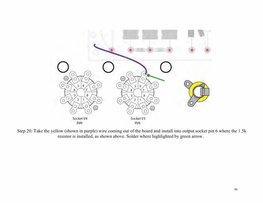
Step 20: Take the yellow (shown in purple) wire coming out of the board and install into output socket pin 6 where the 1.5k resistor is installed, as shown above. Solder where highlighted by green arrow.

97
Step 21: Take the brown from the board, as shown above, and insert end into output socket 1 pin 6, where the 1.5k resistor is installed. Solder where highlighted by green arrow.
98
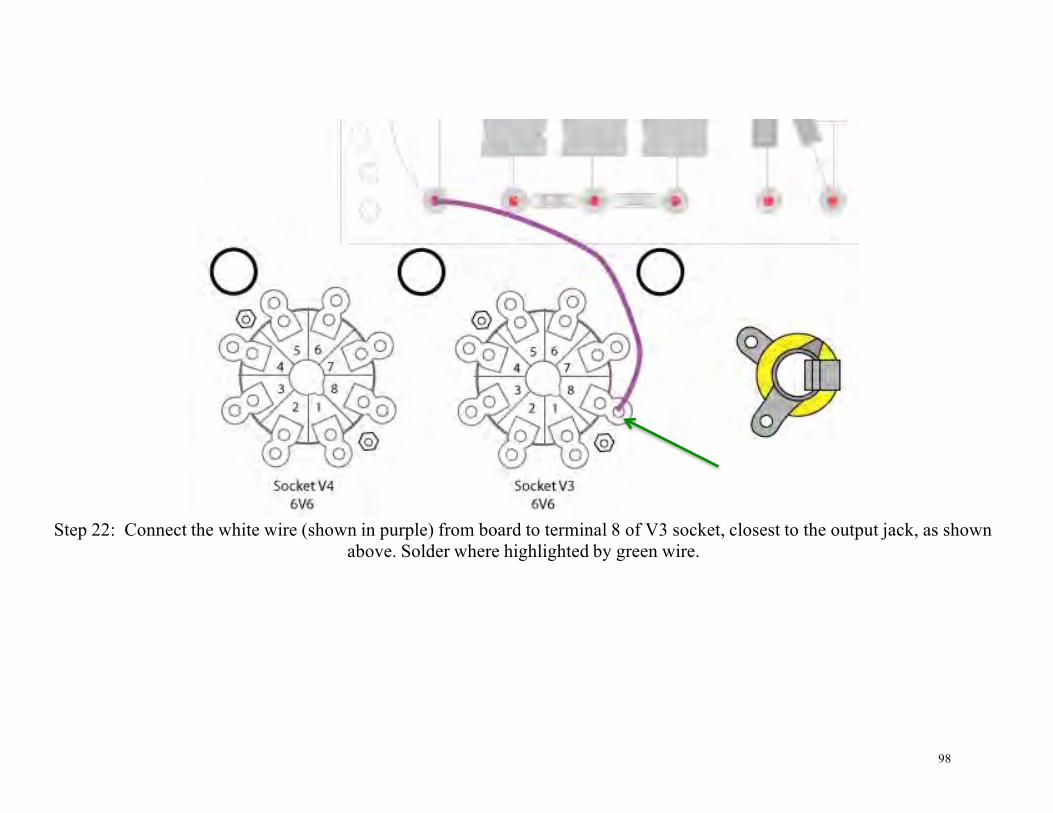
Step 22: Connect the white wire (shown in purple) from board to terminal 8 of V3 socket, closest to the output jack, as shown
above. Solder where highlighted by green wire.
99
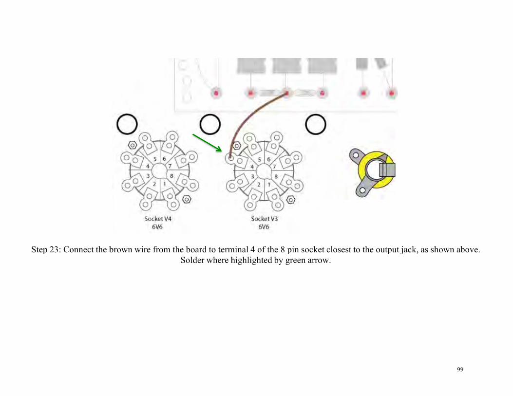
Step 23: Connect the brown wire from the board to terminal 4 of the 8 pin socket closest to the output jack, as shown above. Solder where highlighted by green arrow.
100
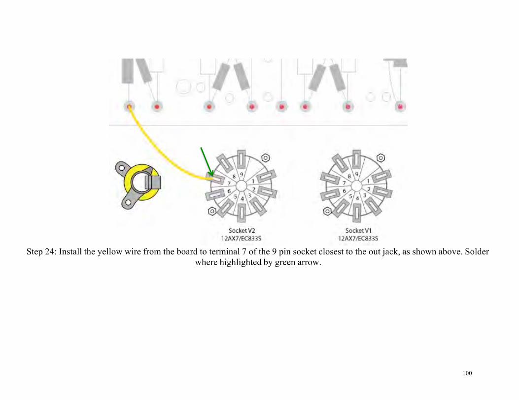
Step 24: Install the yellow wire from the board to terminal 7 of the 9 pin socket closest to the out jack, as shown above. Solder where highlighted by green arrow.

101
Step 25: Install the white wire (shown in purple) from board to terminal 8 of the 9 pin socket closest to the out jack, as shown above. Solder where highlighted by green arrow.

102
Step 26: Install the brown wire from board to terminal 6 of the 9 pin socket closest to the out jack, as shown above. Solder
where highlighted by green arrow.

103
Step 27: Install the yellow wire from board to terminal 1 of the 9 pin socket closest to the out jack, as shown above. Solder
where highlighted by green arrow.

104
Step 28: Install the white wire (shown in purple) from the board to terminal 2 of the 9 pin socket, as shown above. Solder where highlighted by green arrow.

105
Step 29: Install the brown wire from the board to terminal 3 of the 9 pin socket, as shown above. Solder where highlighted by
green arrow.

106
Step 30: Install the yellow wire from the board to terminal 6 of the 9 pin socket, as shown above. Solder where highlighted by green arrow.

107
Step 31: Install the white wire (shown in purple) from the board to terminal 8 AND terminal 3, as shown above. You can use two separate pieces of wire to do this, but it’s easier if you strip about 1” off the end of the wire and thread it through both
solder terminals. Solder at both points highlighted by the green arrows.

108
Step 32: Install the brown wire from the board to terminal 7 of the 9 pin socket, as shown above. Solder where highlighted by green arrow.

109
Step 33: Install the white wire (shown in purple) from the board to terminal 1 of the 9 pin socket, as shown above. Solder where highlighted by green arrow.
110
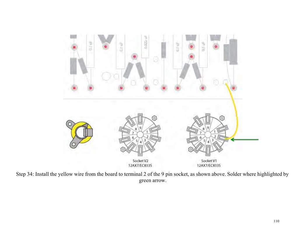
Step 34: Install the yellow wire from the board to terminal 2 of the 9 pin socket, as shown above. Solder where highlighted by
green arrow.

111
Step 35: Wire Channel 1 “Normal” input jacks as shown above. The white wire is show as purple in the diagram above. First thread one end of the 1M resistor through both the shorting terminal and sleeve terminal of the first jack on the top. Then
thread the other end of the 1M resistor through both the tip and the shorting terminal of the second jack. Connect the white wire to the tip of the first jack. Connect the yellow wire to the tip of the second jack. Connect the black wire to the sleeve of
the first jack. Solder at all the points highlighted in yellow.

112
Step 36: Wire Channel 2 “Bright” input jacks. You will do this exactly the same way you just wired the “Normal” input jacks, but this time you connect the black wire to the sleeve of the second jack, and also make a ground connection with a black wire
to lug 1 of VOLUME pot #1.

113
Step 37: Connect the brown and white (shown in purple) wires from the board to Volume 1 as shown above. Solder where
highlighted by green arrows.
114
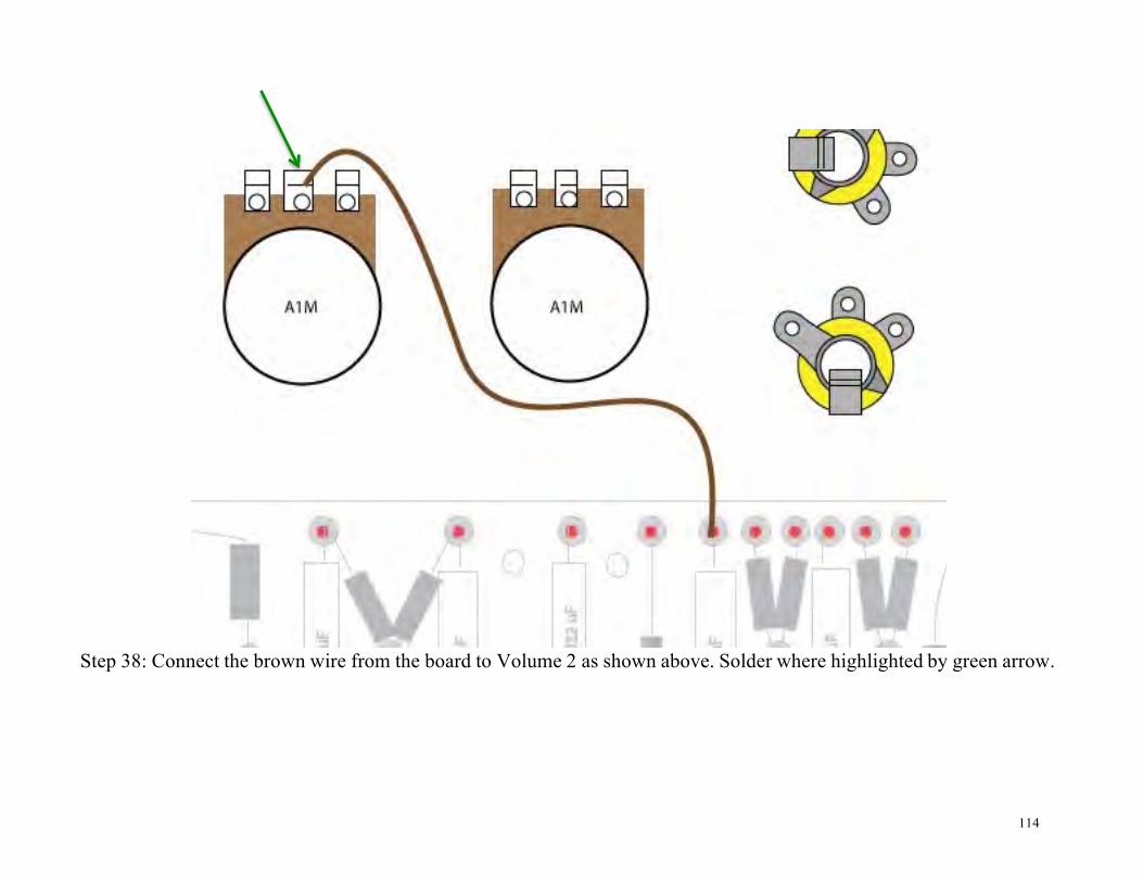
Step 38: Connect the brown wire from the board to Volume 2 as shown above. Solder where highlighted by green arrow.
115
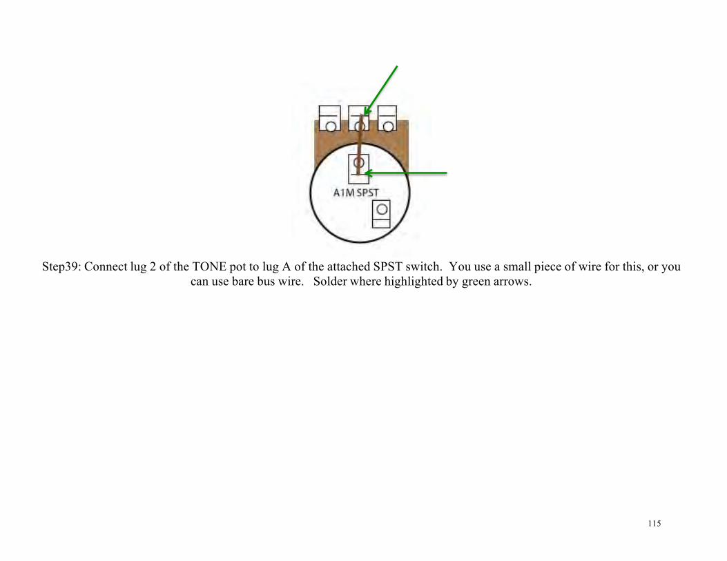
Step39: Connect lug 2 of the TONE pot to lug A of the attached SPST switch. You use a small piece of wire for this, or you
can use bare bus wire. Solder where highlighted by green arrows.

116
Step 40: Connect the brown wire from the board to lug C of the SPDT switch attached to the CUT pot. Solder where
highlighted by the green arrow.

117
Step 41: Use the 22k resistor to jumper between lug 2 of the CUT pot and lug A of the attached SPDT switch. Connect the 25uF capacitor between lug B of the attached SPDT switch and the Circuit Board. You can wrap the capacitor lead around one of the tiers of the turret lug. Be certain to orient the capacitor so that the positive end connects to the switch and the negative
end connects to the circuit board.

118
Step 42: Connect the black wire from the circuit board to the solder terminal lock washer. Solder where highlighted by green arrow. Another wire will be added to this terminal, so try not to get solder in the other hole.

119
S.E./STANDBY/P.P. Switch
There are no actual markings on the rotary switch. The letters and numbers shown in the diagram above are just arbitrary
designators that we have assigned to make it easier to keep track of.

120
Step 1: Connect lug C to the other hole in the solder terminal lock washer. Solder where highlighted by green arrows.

121
NOTEtheorangeclothwireisnowblueclothwire
122
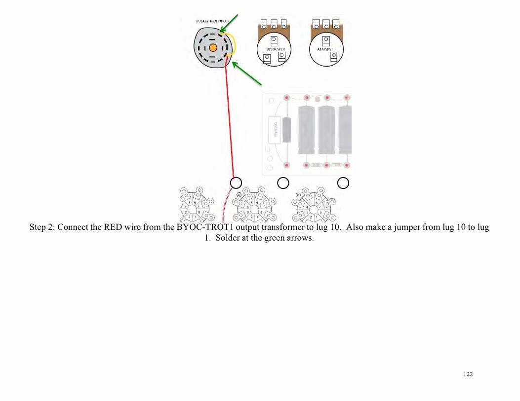
Step 2: Connect the RED wire from the BYOC-TROT1 output transformer to lug 10. Also make a jumper from lug 10 to lug 1. Solder at the green arrows.

123
NOTE:Theorangeclothwireisnowblueclothwire

124
Step 3: Connect the red wire from the circuit board to lug D. Solder where highlighted by green arrows.

125
Step 4: Connect lug B to terminal 8 of the middle 8 pin socket. Solder where highlighted by green arrows.

126
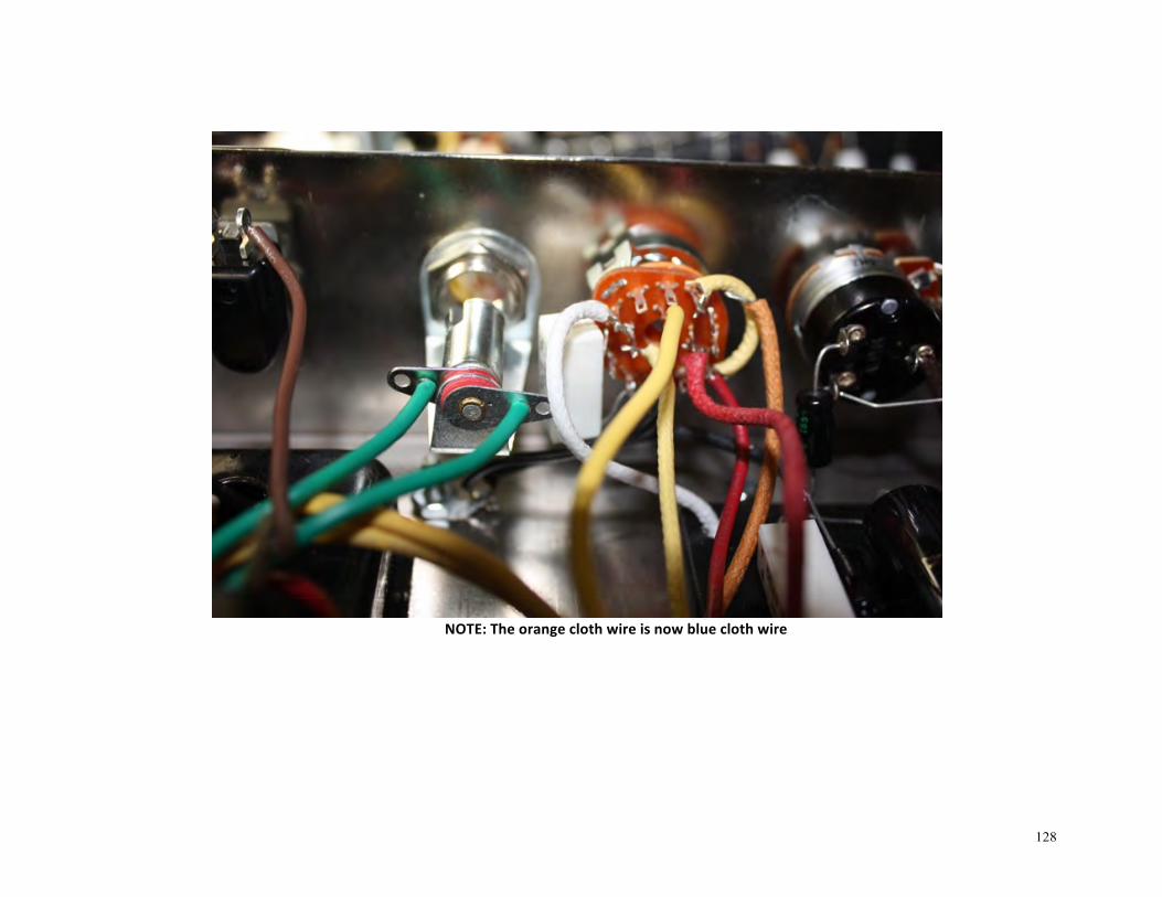
NOTE:Theorangeclothwireisnowblueclothwire
127
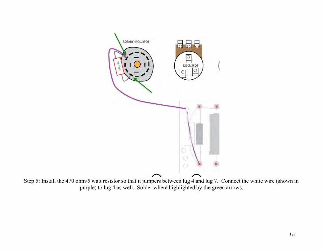
Step 5: Install the 470 ohm/5 watt resistor so that it jumpers between lug 4 and lug 7. Connect the white wire (shown in purple) to lug 4 as well. Solder where highlighted by the green arrows.
128
NOTE:Theorangeclothwireisnowblueclothwire

129
Step 6: Connect lug A to pin 8 of the RECTIFIER socket. Solder where highlighted by green arrows.
130
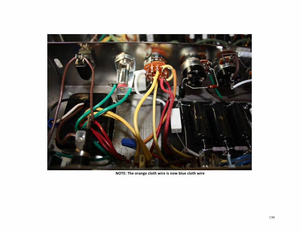
NOTE:Theorangeclothwireisnowblueclothwire

131
Step 7: Take the orange wire from the TROT2 output transformer (Wiring-Step 8) and connect it to lug 12. Also make a jumper from lug 12 to lug 3. Solder where highlighted by green arrows.

132
NOTE:Theorangeclothwireisnowblueclothwire

133
Heater Wiring
134
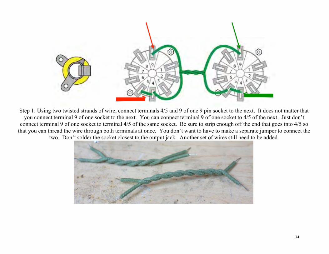
Step 1: Using two twisted strands of wire, connect terminals 4/5 and 9 of one 9 pin socket to the next. It does not matter that you connect terminal 9 of one socket to the next. You can connect terminal 9 of one socket to 4/5 of the next. Just don’t
connect terminal 9 of one socket to terminal 4/5 of the same socket. Be sure to strip enough off the end that goes into 4/5 so that you can thread the wire through both terminals at once. You don’t want to have to make a separate jumper to connect the
two. Don’t solder the socket closest to the output jack. Another set of wires still need to be added.
135

136
Step 2: Using another two twisted strands, connect 4/5 and 9 of the previous 9 pin socket to terminals 2 and 7 of the next 8 pin socket. Just as before, it does not matter which strand goes to 2 and which strand goes to 7. Solder the terminals on the 9 pin
socket, but do not solder the 8 pin socket yet. Another set of wires will be added.

137

138
Step 3: Use another 2 twisted strands to connect terminals 2 and 7 to 2 and 7 of the next socket. As before, solder the first socket, but do not solder the last.

139
140
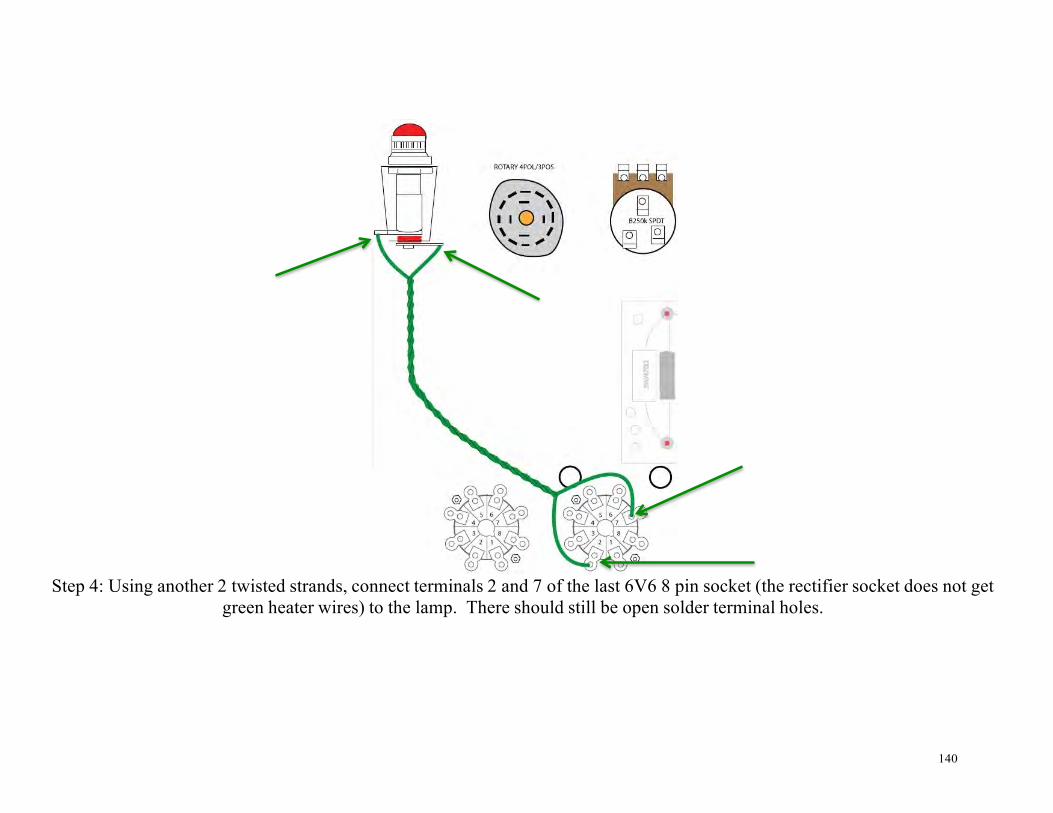
Step 4: Using another 2 twisted strands, connect terminals 2 and 7 of the last 6V6 8 pin socket (the rectifier socket does not get green heater wires) to the lamp. There should still be open solder terminal holes.

141

142
Finishing Up.
1. Install the knobs. The white knob goes on the S.E./Standby/P.P. rotary switch. 2. Install the fuse in the holder. There’s actually a trick to this. Put the fuse into the cap first. Then insert the fuse and cap
into the fuse holder.

143
3. Install the lamp into lamp holder and install jewel lamp cover.

144
4. Install the power cord into the break-away socket.
145
Turning your amp on for the first time
Step 1: Make sure your AC power cord is NOT plugged in. Do NOT install any of the tubes yet. Do not plug a speaker into the speaker jack. Do not plug any instruments into the input jacks. Step 2: Do not test your amp on a metal table or any surface that can conduct electricity. Situate yourself and your amp so that the AC power outlet you will be using is within arm's length. Step 3: Install your amplifier chassis into the cabinet or enclosure that you should have. You should never apply power to the amplifier while it is not inside its cabinet or enclosure. If you insist on supplying power to the amplifier while it is not inside its cabinet or enclosure, the safest way to do so is with the chassis laying on a non- conductive, flame retardant surface with the transformer side facing down and the open side of the chassis facing up, making sure that no foreign objects (especially any of your body parts) are touching any part of the amp. Step 6: Turn the amplifier's power switch on, but still do not plug the power cord in yet. Also turn the S.E./Standby/P.P. switch to “P.P.” mode.
Step 7: Orient the amp so that you can see the indicator light. When you plug the power cord into the AC power supply, you should be able to see the indicator light come on immediately.
Step 8: Double check - the amp is not plugged in; none of the tubes are installed; there are no instruments plugged into the input jacks; there is no speaker plugged into the speaker jack; and the on/off switch is in the on position.
Step 9: Now it is time to plug the amp in. Do not touch the amp itself. Grab only the insulated 3-prong AC power cord and plug it into the AC power supply socket. You should see the indicator light come on immediately. If it does not come on, remove the plug and figure out what you did wrong. If the light does come on, observe the amp

146
for a few moments to make sure there's no sparks, smoke, heat, or burning smells. If you notice anything other than just the indicator light coming on, unplug the power cord immediately.
Step 10: Unplug the AC power cord. Ok....so now you know your power transformer is working properly.
Step 11: With the AC power cord unplugged, the on/off switch in the on position, and no speaker or instruments plugged in, install the 5Y3 rectifier tube. Do NOT install the 12AX7 or 6V6 yet.
Step 12: Plug the AC power cord back in exactly as you did in step 9. Once again, you should see the indicator

147
light come on immediately. Once again, if you notice any sparks, smoke, heat, or burning smells, unplug the power cord immediately and figure out what you did wrong. Take a moment to observe the rectifier tube. You should see that it is beginning to warm up and glow. If it's doing this and the fuse hasn't blown, you can assume
that it is working properly. As the tube starts to get hot, you will probably get a faint smell of something burning. If you'd like to test voltage before proceeding to the next step, you may.
When testing your amp voltages, always keep one hand in your pocket and wear shoes with rubber soles. This doesn't reduce the risk of electrocution, but it will reduce the amount of damage that will be done if you get do electrocuted. It won't make you impervious to electrocution, but the less “grounded” you are, the less the amount of current that will be able to flow through your body. Doing things like going barefoot or holding onto a metal drain pipe with your free hand while working with electricity won't increase the risk of electrocution, but they will increase how well you conduct current to ground, and that increases the amount of damage you can do to yourself if you are electrocuted.
To test the rectified DC voltage, first set your meter to test DC voltage 500V or greater. Then connect the black probe to chassis ground. Then touch the red probe to the turret lug that connects to the positive end of the first 16uF aluminum electrolytic capacitor. You should see somewhere around 425VDC. This voltage can vary by as much as 20volts over or under depending on the actual voltage of your AC power supply. Also keep in mind, that this voltage will drop significantly when the other tubes are added.
Step 13: Unplug the AC power cord again.

148
Step 14: Install the 12AX7/EC833S preamp tubes, but do not install the 6V6 tube yet.
Step 15: Plug the AC power cord back in, just as you did in step 9. You should see the 12AX7 start to glow. If you see this, and there's no smoke and a fuse hasn't blown, you can assume that everything is working properly.
Preamp tubes do not get very hot. They just get warm, so it should not produce any sort of burning smell. If you'd like to test for voltage, you should see approximately 2VDC on the turret lug where the 1.5k resistor; 25uf
aluminum electrolytic capacitor; and brown wire that connects to pin 3 of the first 12AX7 all meet. This voltage can vary by 1/2 a volt.
Step 16: Unplug the AC power cord.
Step17: VERY IMPORTANT BEFORE YOU ADD THE 6V6 TUBES!!! Be sure to plug a speaker into the speaker jack. You should never turn your amp on when the power tube is installed without the proper speaker load. Doing so will damage your output transformer. Plug a speaker into the speaker jack. Make sure the

149
impedance of the speaker is 8 ohms. This is very important too.
Step 18: Install the 6V6 power tube into its socket and turn the volume knobs counter clockwise to their minimum volume level.
Step 19: Plug the AC power cord back into the power socket and repeat all the instructions in step 9 again. You should see the tube start to glow and it should begin to heat up. As the tube starts to get hot, it will probably produce a faint smell. This amp will produce a LOT of heat, so do not be shocked at how hot it gets.
Step 20: Slowly turn the volume knob up and listen for sound coming out of the speaker. You should hear the normal amount of white noise you'd expect to hear coming out of an amp with no input signal.
Step 21: Turn the rotary switch to standby and then turn the power toggle switch off.
Step 22: You are now almost ready to start playing. Please take just a few more minutes to read the operating overview. There are a few things that are unique to this amp.

150
Operating Overview
The most important thing about this amp: Always allow it to be in standby for 3 seconds before switching from S.E.
mode to P.P. mode and vice versa.
Inputs: Your amp has two channels. The typical “Fender” inputs: 2 x normal inputs; 2 x bright inputs. Try jumpering the two
channels with a patch cable for a “linked” tone.
Volume Knobs: The knob on the left controls the “normal” volume. The knob on the right controls the “bright” volume. Even when you’re only plugged into one channel, you can still expect some very minor interaction from the volume knob of the other
channel.
Tone: Pretty straight forward…clockwise produces a brighter tone. Counter-clockwise produces a darker tone. Turning it all the way counter-clockwise with flip a switch and remove the tone stack completely. Expect to hear a bit of a volume boost
when you do this. Turn the tone knob off for a “champ” EQ.
151
Cut: This is kind of like a presence knob. It controls the amount of negative feedback. Turning it clockwise increases the amount of negative feedback. The knob may seem like it’s wired backwards, because turning it up will reduce the amount of gain. The 5F1 Champ had it’s negative feedback loop hardwired. For a more “champ” sound, turn the cut knob full turn clockwise. For the 5E3 Deluxe sound, turn it full turn counter-clockwise till the switch turns off. This will remove the negative feedback loop from the circuit. S.E./standby/P.P: This allows you to select between Single Ended/Class A output just like the 5F1 Champ or Push- Pull/Class AB output just like the 5E3 Deluxe.
Power Switch: Pretty straight forward here too…in the up position, the power is on. In the down position, the power is off.
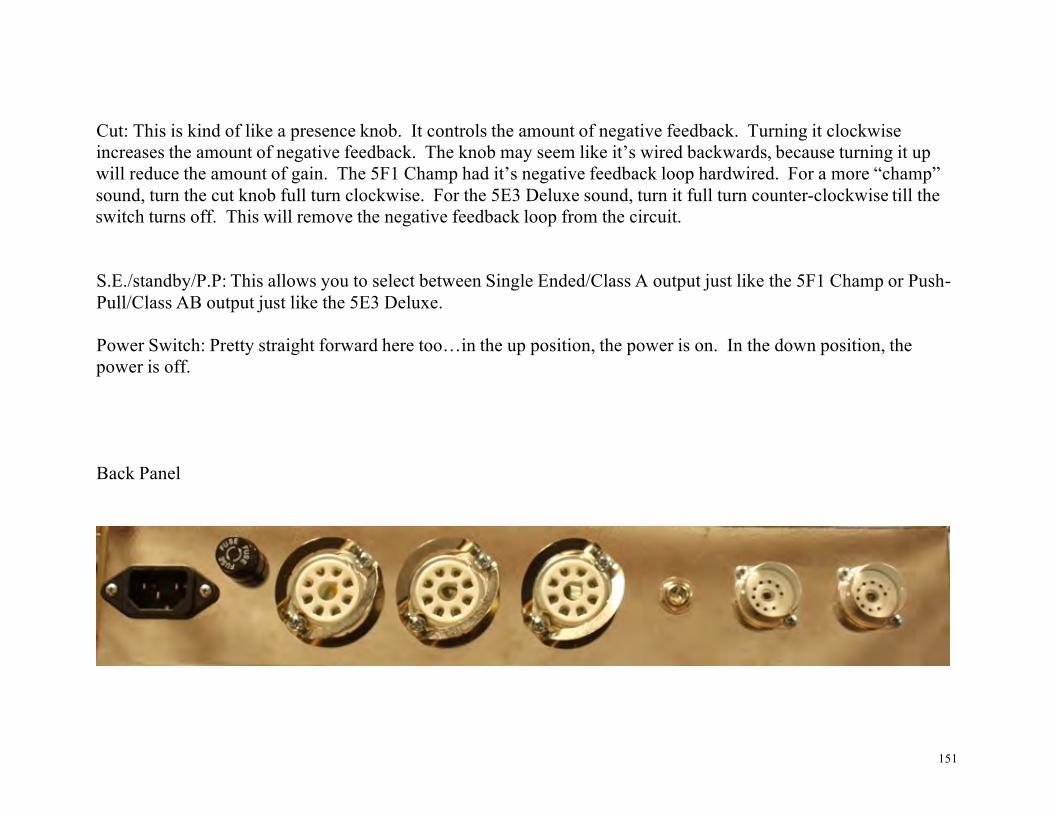
Back Panel

152
Power Cord Socket: Plug your power cord in to this guy.
Fuse Holder: This is where the fuse goes. Always use a 3AG 2 slo-blo amp fuse.
Speaker Jack: Insert speaker cable here. ALWAYS USE AN 8 OHM SPEAKER OR CABINET RATED FOR AT LEAST 15 WATTS

153
Diagrams and Schematic
Circuit board (top side)

!54
Circuit Board Wiring (underside)
0
155
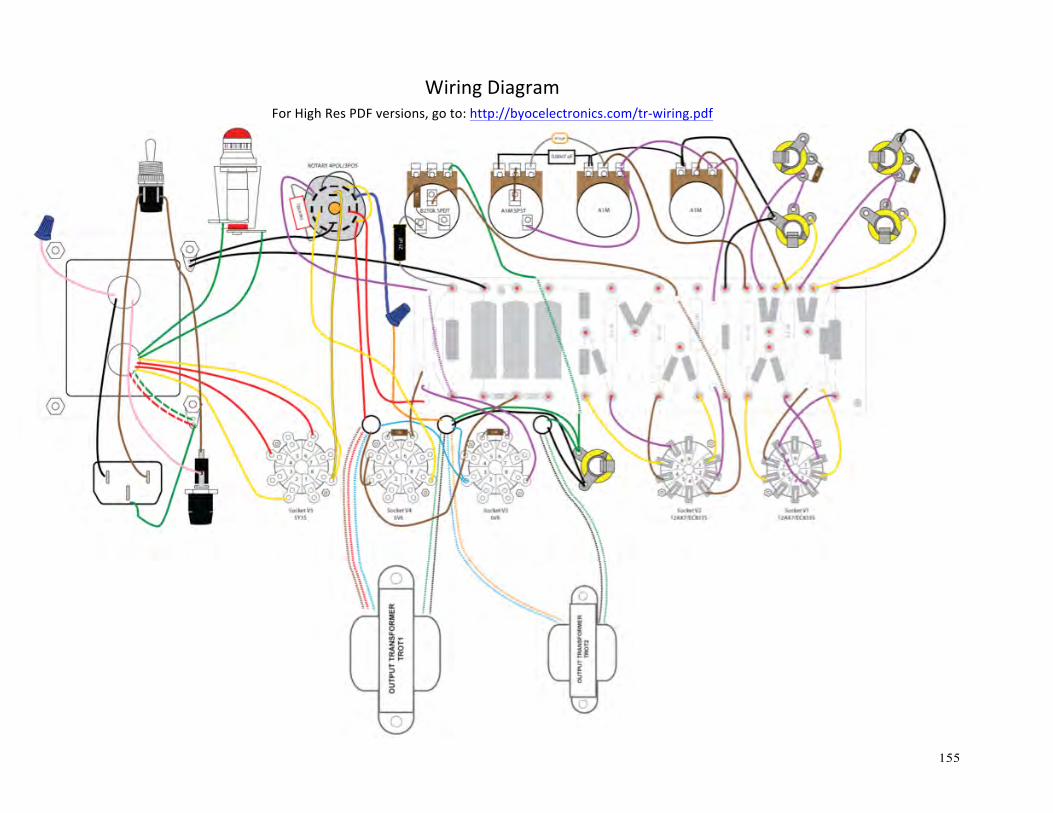
WiringDiagram
ForHighResPDFversions,goto:http://byocelectronics.com/tr-wiring.pdf

156
Heater Wiring
for hi res pdf go to http://www.buildyourownclone.com/tr heater
157
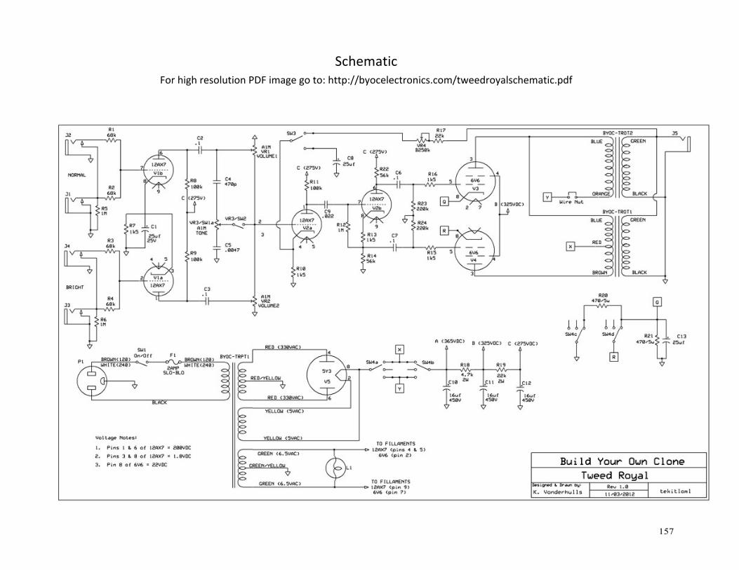
SchematicForhighresolutionPDFimagegoto:http://byocelectronics.com/tweedroyalschematic.pdf

158
For technical support, visit http://www.byocelectronics.com/board
Written by: J. O’Mealey & K. Vonderhulls
Artwork by: J. O’Mealey & K. Vonderhulls
Edited by: R. Matthews & K. Vonderhulls
Copyright BYOC, Inc. 2012