BSI Standards Publication - iso-iran.ir EN 60079-1-2014 , Explosive... · National foreword This...
96
BSI Standards Publication Explosive atmospheres Part 1: Equipment protection by flameproof enclosures “d” BS EN 60079-1:2014
Transcript of BSI Standards Publication - iso-iran.ir EN 60079-1-2014 , Explosive... · National foreword This...

BSI Standards Publication
Explosive atmospheres
Part 1: Equipment protection by flameproof enclosures “d”
BS EN 60079-1:2014

National foreword
This British Standard is the UK implementation of EN 60079-1:2014. It is identical to IEC 60079-1:2014. It supersedes BS EN 60079-1:2007 which is withdrawn.
BSI, as a member of CENELEC is obliged to publish BS EN 60079-1 as aBritish Standard. However, attention is drawn to the fact that during thedevelopment of this European Standard, the UK voted against its approvalas a European Standard. The reason for this disapproval was that the passcriteria for the test relating to cemented joints in subclause 6.1.2 is con-sidered to be not as robust when compared with the previously published edition.
Other National Standard Bodies have also recorded a negative vote on thedocument citing the identical concern in the difference between the 2007edition and the 2014 edition. Many manufacturers had no difficulty incomplying with the previous requirement when choosing appropriate ce-ments and the UK committee did not see any justification for revising the requirement.
The UK participation in its preparation was entrusted to TechnicalCommittee EXL/31, Equipment for explosive atmospheres.
A list of organizations represented on this committee can be obtained onrequest to its secretary.
This publication does not purport to include all the necessary provisions ofa contract. Users are responsible for its correct application.
© The British Standards Institution 2014.Published by BSI Standards Limited 2014
ISBN 978 0 580 75475 3ICS 13.230; 29.260.20
Compliance with a British Standard cannot confer immunity fromlegal obligations.
This British Standard was published under the authority of theStandards Policy and Strategy Committee on 31 October 2014.
Amendments/corrigenda issued since publication
Date Text affected
BRITISH STANDARDBS EN 60079-1:2014

EUROPEAN STANDARD
NORME EUROPÉENNE
EUROPÄISCHE NORM
EN 60079-1
October 2014
ICS 29.260.20 Supersedes EN 60079-1:2007
English Version
Explosive atmospheres - Part 1: Equipment protection by flameproof enclosures "d"
(IEC 60079-1:2014)
Atmosphères explosives - Partie 1: Protection de l'appareil par enveloppes antidéflagrantes "d"
(CEI 60079-1:2014)
Explosionsgefährdete Bereiche - Teil 1: Geräteschutz durch druckfeste Kapselung "d"
(IEC 60079-1:2014)
This European Standard was approved by CENELEC on 2014-08-01. CENELEC members are bound to comply with the CEN/CENELEC Internal Regulations which stipulate the conditions for giving this European Standard the status of a national standard without any alteration.
Up-to-date lists and bibliographical references concerning such national standards may be obtained on application to the CEN-CENELEC Management Centre or to any CENELEC member.
This European Standard exists in three official versions (English, French, German). A version in any other language made by translation under the responsibility of a CENELEC member into its own language and notified to the CEN-CENELEC Management Centre has the same status as the official versions.
CENELEC members are the national electrotechnical committees of Austria, Belgium, Bulgaria, Croatia, Cyprus, the Czech Republic, Denmark, Estonia, Finland, Former Yugoslav Republic of Macedonia, France, Germany, Greece, Hungary, Iceland, Ireland, Italy, Latvia, Lithuania, Luxembourg, Malta, the Netherlands, Norway, Poland, Portugal, Romania, Slovakia, Slovenia, Spain, Sweden, Switzerland, Turkey and the United Kingdom.
European Committee for Electrotechnical Standardization Comité Européen de Normalisation Electrotechnique
Europäisches Komitee für Elektrotechnische Normung
CEN-CENELEC Management Centre: Avenue Marnix 17, B-1000 Brussels
© 2014 CENELEC All rights of exploitation in any form and by any means reserved worldwide for CENELEC Members.
Ref. No. EN 60079-1:2014 E
BS EN 60079-1:2014

EN 60079-1:2014 - 2 -
Foreword
The text of document 31/1111/FDIS, future edition 7 of IEC 60079-1, prepared by IEC/TC 31 "Equipment for explosive atmospheres" was submitted to the IEC-CENELEC parallel vote and approved by CENELEC as EN 60079-1:2014. The following dates are fixed:
• latest date by which the document has to be implemented at national level by publication of an identical national standard or by endorsement
(dop) 2015-05-01
• latest date by which the national standards conflicting with the document have to be withdrawn
(dow) 2017-08-01
This document supersedes EN 60079-1:2007. Attention is drawn to the possibility that some of the elements of this document may be the subject of patent rights. CENELEC [and/or CEN] shall not be held responsible for identifying any or all such patent rights. This document has been prepared under a mandate given to CENELEC by the European Commission and the European Free Trade Association, and supports essential requirements of EU Directive. For the relationship with EU Directive see informative Annex ZZ, which is an integral part of this document.
Endorsement notice
The text of the International Standard IEC 60079-1:2014 was approved by CENELEC as a European Standard without any modification.
BS EN 60079-1:2014
- 3 - EN 60079-1:2014
Annex ZA (normative)
Normative references to international publications with their corresponding European publications
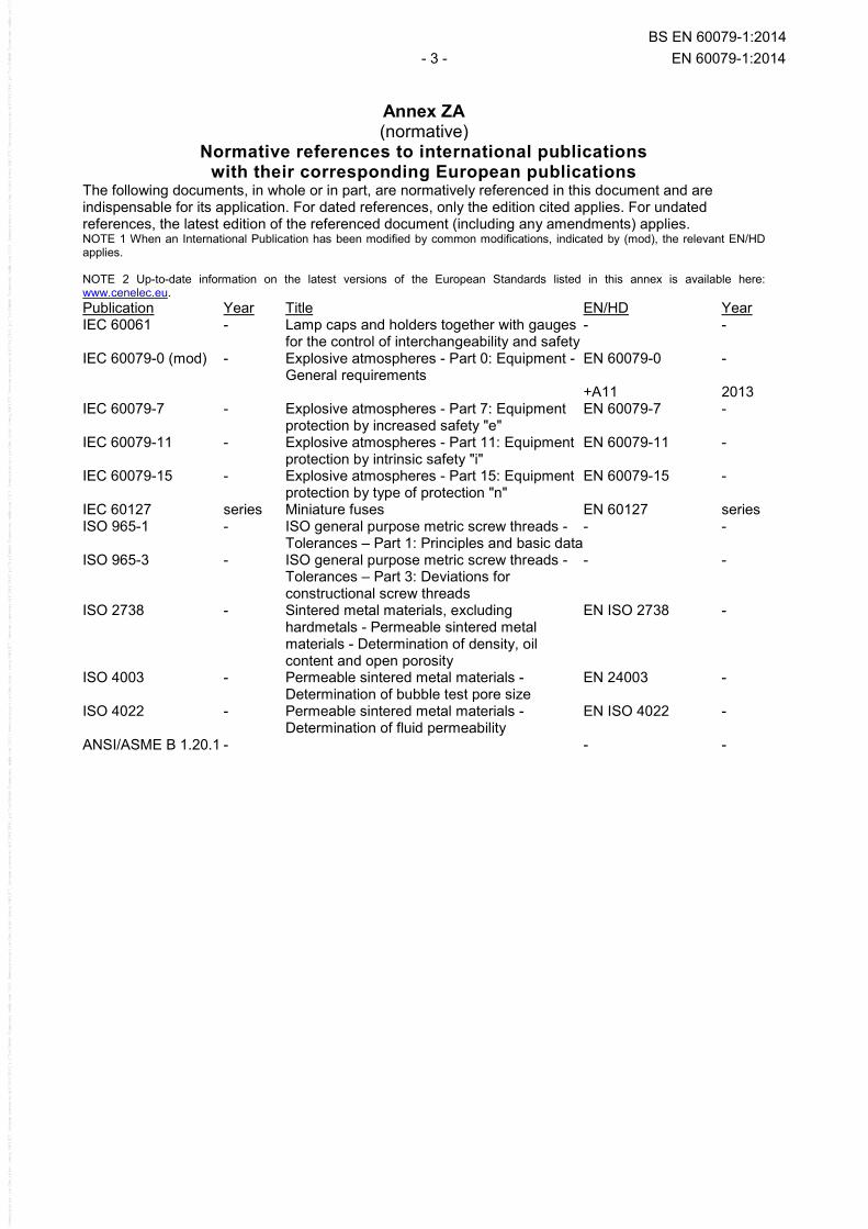
The following documents, in whole or in part, are normatively referenced in this document and are indispensable for its application. For dated references, only the edition cited applies. For undated references, the latest edition of the referenced document (including any amendments) applies. NOTE 1 When an International Publication has been modified by common modifications, indicated by (mod), the relevant EN/HD applies. NOTE 2 Up-to-date information on the latest versions of the European Standards listed in this annex is available here: www.cenelec.eu. Publication Year Title EN/HD Year IEC 60061 - Lamp caps and holders together with gauges
for the control of interchangeability and safety - -
IEC 60079-0 (mod) - Explosive atmospheres - Part 0: Equipment - General requirements
EN 60079-0 -
+A11 2013 IEC 60079-7 - Explosive atmospheres - Part 7: Equipment
protection by increased safety "e" EN 60079-7 -
IEC 60079-11 - Explosive atmospheres - Part 11: Equipment protection by intrinsic safety "i"
EN 60079-11 -
IEC 60079-15 - Explosive atmospheres - Part 15: Equipment protection by type of protection "n"
EN 60079-15 -
IEC 60127 series Miniature fuses EN 60127 series ISO 965-1 - ISO general purpose metric screw threads -
Tolerances – Part 1: Principles and basic data - -
ISO 965-3 - ISO general purpose metric screw threads - Tolerances – Part 3: Deviations for constructional screw threads
- -
ISO 2738 - Sintered metal materials, excluding hardmetals - Permeable sintered metal materials - Determination of density, oil content and open porosity
EN ISO 2738 -
ISO 4003 - Permeable sintered metal materials - Determination of bubble test pore size
EN 24003 -
ISO 4022 - Permeable sintered metal materials - Determination of fluid permeability
EN ISO 4022 -
ANSI/ASME B 1.20.1 - - -
BS EN 60079-1:2014

EN 60079-1:2014 - 4 -
Annex ZY (informative)
Significant changes between this European Standard and EN 60079-1:2007
This European Standard supersedes EN 60079-1:2007.
The significant changes with respect to EN 60079-1:2007 are as listed below.
Type
Significant Changes Clause Minor and editorial changes
Extension Major technical changes
Normative references (Removal of the edition date from the reference for IEC 60079-0)
2 X
Requirements for level of protection “da” (Catalytic sensors for combustible gas detectors)
4.2 X
Requirements for level of protection “dc” (“Enclosed break” devices from IEC 60079-15)
4.4, 15.5 X
Flameproof joints, General requirements (Documentation clarification and examples of corrosion inhibiting grease)
5.1 X
Flameproof joints, General requirements (Specific Conditions of Use that joints are not intended to be repaired)
5.1 X
Flameproof joints, General requirements (Electroplating more than 0.008 mm think)
5.1 X
Non-threaded joints, Gap (i) (Intentional gaps between surface for flanged joints)
5.2.2 X
Serrated joints (Use and test requirements)
5.2.8 X
Multi-step joints (Not less than 3 adjacent segments and two path changes)
5.2.9 X
Minimum width of joint and maximum gap for enclosures of groups IIA and IIB (Maximum gaps for flanged, cylindrical or spigot joints of 9,5 mm minimum width and volume greater than 2,000 cm3)
Table 2 X
Minimum width of joint and maximum gap for enclosures of groups I, IIA, IIB and IIC (ISO 80000-1 for constructional value rounding)
Table 2, Table 3
X
Cylindrical threaded joints (ISO 965-1 standard in respect of thread form or quality of fit)
Table 4 X
Taper threaded joints (External and internal thread construction)
Table 5 X
Cemented joints (Supplemental mechanical means of securement) 6.1.2 C1
Cemented joints (Evaluation criteria if there is leakage)
6.1.2 X
Fused glass joints (Glass-to-metal joints)
6.2 X
BS EN 60079-1:2014

- 5 - EN 60079-1:2014
Type
Significant Changes Clause Minor and editorial changes
Extension Major technical changes
Thermal tests of breathing and draining devices (Temperature class based on external surface temperature after the 10 min test period)
10.9.3.2 X
Test of the ability of the breathing and draining device to withstand pressure (Relocated from before thermal tests to after the non-transmission test)
10.9.3.4 X
Ex component certificate (Service temperature range for non-metallic enclosures per IEC 60079-0)
10.9.4 X
Fasteners and openings (Relocation of blanking element content to Clauses 13.8 and C.2.3)
11 X
Fasteners and openings, Property class or yield stress (Certificate specific condition of use)
11.3 X
Fasteners and openings (Openings in the wall of the enclosure)
11.8 X
Materials (Material limitation in acetylene atmospheres)
12.8 C2
Entries for flameproof enclosures, General (Metric and NPT threaded entries)
13.1 X
Entries for flameproof enclosures, General (Group I non-threaded joints)
13.1 X
Entries for flameproof enclosures, Non-threaded holes (Group I application)
13.3 X
Entries for flameproof enclosures, Cable glands (Group I application)
13.4 X
Cable glands, Conduit sealing devices (Documentation to facilitate mounting)
13.4,13.5 X
Plugs and sockets and cable couplers (Load requirement for arc-quenching test)
13.6.4 C3
Bushings (Documentation to facilitate mounting)
13.7 X
Blanking elements (Relocated from Clause 11)
13.8 X
Verification and tests (Maximum surface temperature conditions)
Table 6 X
Type tests (Sequence and number of samples for tests)
15 X
Determination of explosion pressure, General (Devices that can cause turbulence)
15.2.2.2 X
Determination of explosion pressure, General (Number of tests for Group IIC)
15.2.2.2 X
Determination of explosion pressure, General (Pressure pilling for Group IIB)
15.2.2.4 X
Determination of explosion pressure, General (Equipment marked for a single gas)
15.2.2.5 X
Overpressure test, General (Low ambient overpressure tests not required)
15.2.3 X
BS EN 60079-1:2014

EN 60079-1:2014 - 6 -
Type
Significant Changes Clause Minor and editorial changes
Extension Major technical changes
Overpressure test – First method (static) (3 times option when routine batch testing)
15.2.3.2 X
Overpressure test – First method (static) (Adjustment for low ambient due to small size of equipment)
15.2.3.2 X
Overpressure test – Second method (dynamic) (Number of tests to be made)
15.2.3.3 X
Test for non-transmission of an internal ignition (Clarification regarding grease)
15.3 X
Reduction in length of a threaded joint for non-transmission test (ISO 965-1 and 965-3 standards in respect of thread form and quality of fit)
Table 9 X
Test factors to increase pressure or test gap (Group IIC adjustments for elevated ambients)
Table 10 X
Test for non-transmission of an internal ignition, Groups I, IIA and IIB (Number of tests to be made)
15.3.2.3 X
Test for non-transmission of an internal ignition, Group IIC testing by increased gap (Number of tests to be made)
15.3.3.2 X
Test for non-transmission of an internal ignition, Group IIC (Oxygen enrichment of test gases)
15.3.3.4 X
Thermal tests of enclosures with breathing and draining devices (Temperature class based on external surface temperature after the 10 min test period)
15.4.3.1 X
Tests for “dc” devices (“Enclosed break” devices from IEC 60079-15)
15.5 X
Routine tests, General (Adjustment for low ambient due to small size of equipment)
16.1.2 X
Routine tests, General (Options when second method is chosen)
16.1.3 X
Routine tests, General (Welded joint inspection options)
16.3 X
Routine tests, General (Allowance for batch testing)
16.6 X
Switchgear for Group I (Clarifying need for compliance with EPL Mb types of protection)
17.2.2, 17.2.3
X
Non-metallic enclosures and non-metallic parts of enclosures, General (Exception for cemented joints)
19.1 X
Non-metallic enclosures and non-metallic parts of enclosures, Resistance to tracking and creepage distances (Reference to both IEC 60079-7 and or IEC 60079-15)
19.2 X
Non-metallic enclosures and non-metallic parts of enclosures, Requirements for type tests (Clarification of test sequence)
19.3 X
BS EN 60079-1:2014
- 7 - EN 60079-1:2014
Type
Significant Changes Clause Minor and editorial changes
Extension Major technical changes
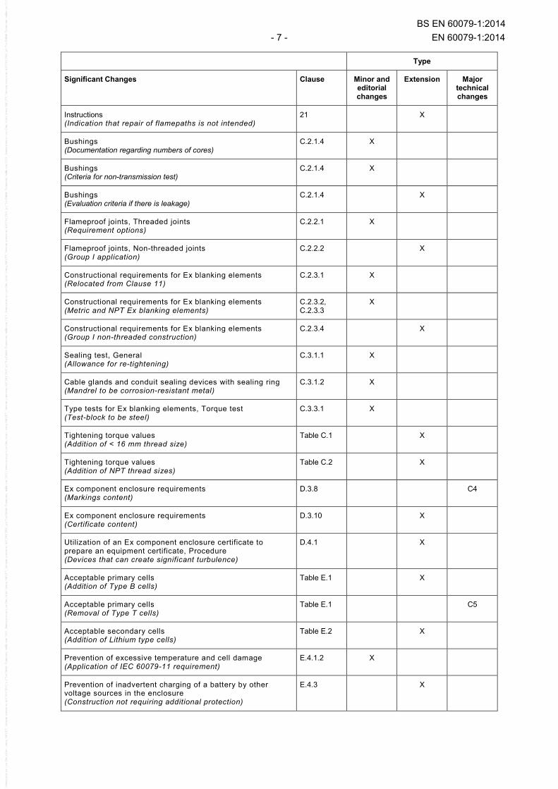
Instructions (Indication that repair of flamepaths is not intended)
21 X
Bushings (Documentation regarding numbers of cores)
C.2.1.4 X
Bushings (Criteria for non-transmission test)
C.2.1.4 X
Bushings (Evaluation criteria if there is leakage)
C.2.1.4 X
Flameproof joints, Threaded joints (Requirement options)
C.2.2.1 X
Flameproof joints, Non-threaded joints (Group I application)
C.2.2.2 X
Constructional requirements for Ex blanking elements (Relocated from Clause 11)
C.2.3.1 X
Constructional requirements for Ex blanking elements (Metric and NPT Ex blanking elements)
C.2.3.2, C.2.3.3
X
Constructional requirements for Ex blanking elements (Group I non-threaded construction)
C.2.3.4 X
Sealing test, General (Allowance for re-tightening)
C.3.1.1 X
Cable glands and conduit sealing devices with sealing ring (Mandrel to be corrosion-resistant metal)
C.3.1.2 X
Type tests for Ex blanking elements, Torque test (Test-block to be steel)
C.3.3.1 X
Tightening torque values (Addition of < 16 mm thread size)
Table C.1 X
Tightening torque values (Addition of NPT thread sizes)
Table C.2 X
Ex component enclosure requirements (Markings content)
D.3.8 C4
Ex component enclosure requirements (Certificate content)
D.3.10 X
Utilization of an Ex component enclosure certificate to prepare an equipment certificate, Procedure (Devices that can create significant turbulence)
D.4.1 X
Acceptable primary cells (Addition of Type B cells)
Table E.1 X
Acceptable primary cells (Removal of Type T cells)
Table E.1 C5
Acceptable secondary cells (Addition of Lithium type cells)
Table E.2 X
Prevention of excessive temperature and cell damage (Application of IEC 60079-11 requirement)
E.4.1.2 X
Prevention of inadvertent charging of a battery by other voltage sources in the enclosure (Construction not requiring additional protection)
E.4.3 X
BS EN 60079-1:2014
EN 60079-1:2014 - 8 -
Type
Significant Changes Clause Minor and editorial changes
Extension Major technical changes
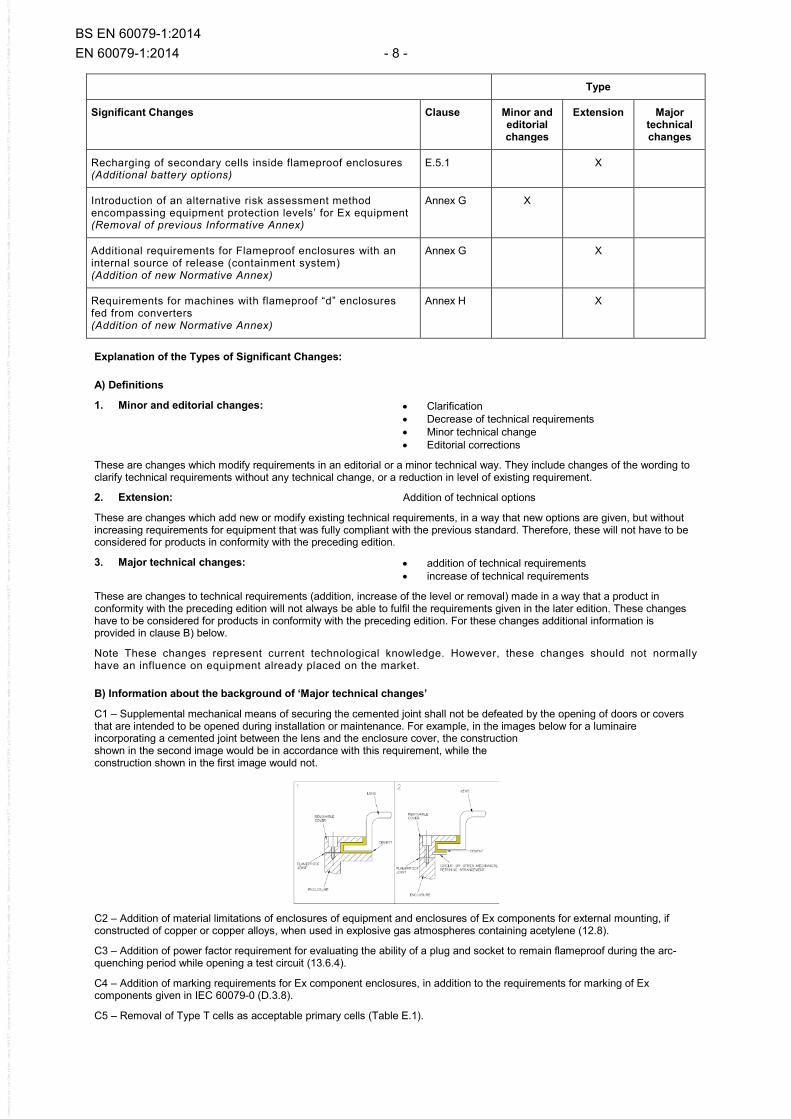
Recharging of secondary cells inside flameproof enclosures (Additional battery options)
E.5.1 X
Introduction of an alternative risk assessment method encompassing equipment protection levels’ for Ex equipment (Removal of previous Informative Annex)
Annex G X
Additional requirements for Flameproof enclosures with an internal source of release (containment system) (Addition of new Normative Annex)
Annex G X
Requirements for machines with flameproof “d” enclosures fed from converters (Addition of new Normative Annex)
Annex H X
Explanation of the Types of Significant Changes:
A) Definitions
1. Minor and editorial changes: • Clarification • Decrease of technical requirements • Minor technical change • Editorial corrections
These are changes which modify requirements in an editorial or a minor technical way. They include changes of the wording to clarify technical requirements without any technical change, or a reduction in level of existing requirement.
2. Extension: Addition of technical options
These are changes which add new or modify existing technical requirements, in a way that new options are given, but without increasing requirements for equipment that was fully compliant with the previous standard. Therefore, these will not have to be considered for products in conformity with the preceding edition.
3. Major technical changes: • addition of technical requirements • increase of technical requirements
These are changes to technical requirements (addition, increase of the level or removal) made in a way that a product in conformity with the preceding edition will not always be able to fulfil the requirements given in the later edition. These changes have to be considered for products in conformity with the preceding edition. For these changes additional information is provided in clause B) below.
Note These changes represent current technological knowledge. However, these changes should not normally have an influence on equipment already placed on the market.
B) Information about the background of ‘Major technical changes’
C1 – Supplemental mechanical means of securing the cemented joint shall not be defeated by the opening of doors or covers that are intended to be opened during installation or maintenance. For example, in the images below for a luminaire incorporating a cemented joint between the lens and the enclosure cover, the construction shown in the second image would be in accordance with this requirement, while the construction shown in the first image would not.
C2 – Addition of material limitations of enclosures of equipment and enclosures of Ex components for external mounting, if constructed of copper or copper alloys, when used in explosive gas atmospheres containing acetylene (12.8).
C3 – Addition of power factor requirement for evaluating the ability of a plug and socket to remain flameproof during the arc-quenching period while opening a test circuit (13.6.4).
C4 – Addition of marking requirements for Ex component enclosures, in addition to the requirements for marking of Ex components given in IEC 60079-0 (D.3.8).
C5 – Removal of Type T cells as acceptable primary cells (Table E.1).
BS EN 60079-1:2014
- 9 - EN 60079-1:2014
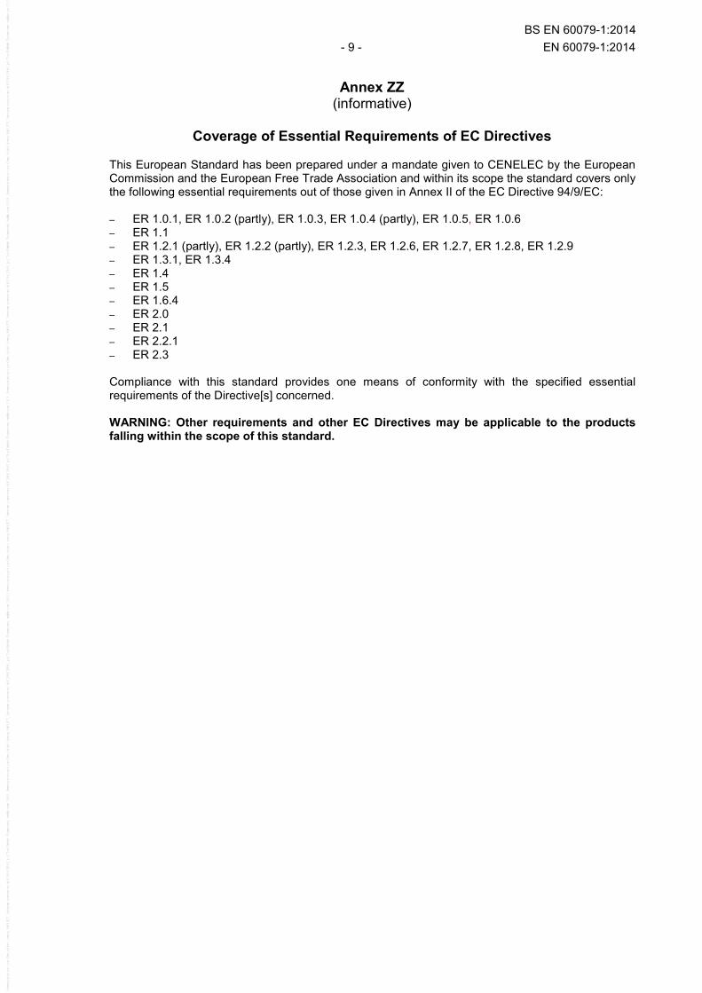
Annex ZZ
(informative)
Coverage of Essential Requirements of EC Directives This European Standard has been prepared under a mandate given to CENELEC by the European
Commission and the European Free Trade Association and within its scope the standard covers only the following essential requirements out of those given in Annex II of the EC Directive 94/9/EC: – ER 1.0.1, ER 1.0.2 (partly), ER 1.0.3, ER 1.0.4 (partly), ER 1.0.5, ER 1.0.6 – ER 1.1 – ER 1.2.1 (partly), ER 1.2.2 (partly), ER 1.2.3, ER 1.2.6, ER 1.2.7, ER 1.2.8, ER 1.2.9 – ER 1.3.1, ER 1.3.4 – ER 1.4 – ER 1.5 – ER 1.6.4 – ER 2.0 – ER 2.1 – ER 2.2.1 – ER 2.3
Compliance with this standard provides one means of conformity with the specified essential requirements of the Directive[s] concerned.
WARNING: Other requirements and other EC Directives may be applicable to the products
falling within the scope of this standard.
BS EN 60079-1:2014

– 10 – IEC 60079-1:2014 © IEC 2014
CONTENTS
1 Scope ............................................................................................................................ 16 2 Normative references .................................................................................................... 16 3 Terms and definitions .................................................................................................... 17 4 Level of protection (equipment protection level, EPL) .................................................... 19
4.1 General ................................................................................................................. 19 4.2 Requirements for level of protection “da” .............................................................. 19 4.3 Requirements for level of protection “db” .............................................................. 20 4.4 Requirements for level of protection “dc” ............................................................... 20
4.4.1 General ......................................................................................................... 20 4.4.2 Construction of “dc” devices .......................................................................... 20 4.4.3 Tests for “dc” devices .................................................................................... 20
5 Flameproof joints ........................................................................................................... 21 5.1 General requirements ........................................................................................... 21 5.2 Non-threaded joints .............................................................................................. 22
5.2.1 Width of joints (L) .......................................................................................... 22 5.2.2 Gap (i) ........................................................................................................... 22 5.2.3 Spigot joints................................................................................................... 22 5.2.4 Holes in joint surfaces ................................................................................... 23 5.2.5 Conical joints ................................................................................................. 25 5.2.6 Joints with partial cylindrical surfaces (not permitted for Group IIC) ............... 25 5.2.7 Flanged joints for acetylene atmospheres ...................................................... 26 5.2.8 Serrated joints ............................................................................................... 26 5.2.9 Multi-step joints ............................................................................................. 27
5.3 Threaded joints ..................................................................................................... 30 5.4 Gaskets (including O-rings) ................................................................................... 30 5.5 Equipment using capillaries .................................................................................. 32
6 Sealed joints.................................................................................................................. 32 6.1 Cemented joints .................................................................................................... 32
6.1.1 General ......................................................................................................... 32 6.1.2 Mechanical strength....................................................................................... 32 6.1.3 Width of cemented joints ............................................................................... 33
6.2 Fused glass joints ................................................................................................. 33 6.2.1 General ......................................................................................................... 33 6.2.2 Width of fused glass joints ............................................................................. 33
7 Operating rods ............................................................................................................... 33 8 Supplementary requirements for shafts and bearings..................................................... 34
8.1 Joints of shafts ..................................................................................................... 34 8.1.1 General ......................................................................................................... 34 8.1.2 Cylindrical joints ............................................................................................ 34 8.1.3 Labyrinth joints .............................................................................................. 34 8.1.4 Joints with floating glands .............................................................................. 34
8.2 Bearings ............................................................................................................... 36 8.2.1 Sleeve bearings ............................................................................................. 36 8.2.2 Rolling-element bearings ............................................................................... 36
BS EN 60079-1:2014

IEC 60079-1:2014 © IEC 2014 – 11 –
9 Light-transmitting parts .................................................................................................. 36 10 Breathing and draining devices which form part of a flameproof enclosure .................... 37
10.1 General ................................................................................................................. 37 10.2 Openings for breathing or draining ........................................................................ 37 10.3 Composition limits ................................................................................................. 37 10.4 Dimensions ........................................................................................................... 37 10.5 Elements with measurable paths ........................................................................... 37 10.6 Elements with non-measurable paths .................................................................... 37 10.7 Removable devices ............................................................................................... 38
10.7.1 General ......................................................................................................... 38 10.7.2 Mounting arrangements of the elements ........................................................ 38
10.8 Mechanical strength .............................................................................................. 38 10.9 Breathing devices and draining devices when used as Ex components ................. 38
10.9.1 General ......................................................................................................... 38 10.9.2 Mounting arrangements of the elements and components .............................. 38 10.9.3 Type tests for breathing and draining devices used as Ex components .......... 38 10.9.4 Ex component certificate ............................................................................... 41
11 Fasteners and openings ................................................................................................ 42 12 Materials ....................................................................................................................... 43 13 Entries for flameproof enclosures .................................................................................. 44
13.1 General ................................................................................................................. 44 13.2 Threaded holes ..................................................................................................... 44 13.3 Non-threaded holes (for Group I only) ................................................................... 44 13.4 Cable glands ......................................................................................................... 45 13.5 Conduit sealing devices ........................................................................................ 45 13.6 Plugs and sockets and cable couplers .................................................................. 46 13.7 Bushings ............................................................................................................... 47 13.8 Blanking elements................................................................................................. 47
14 Verification and tests ..................................................................................................... 47 15 Type tests ..................................................................................................................... 48
15.1 General ................................................................................................................. 48 15.2 Tests of ability of the enclosure to withstand pressure .......................................... 49
15.2.1 General ......................................................................................................... 49 15.2.2 Determination of explosion pressure (reference pressure) ............................. 49 15.2.3 Overpressure test .......................................................................................... 52
15.3 Test for non-transmission of an internal ignition .................................................... 53 15.3.1 General ......................................................................................................... 53 15.3.2 Electrical equipment of Groups I, IIA and IIB.................................................. 55 15.3.3 Electrical equipment of Group lIC .................................................................. 56
15.4 Tests of flameproof enclosures with breathing and draining devices ..................... 57 15.4.1 General ......................................................................................................... 57 15.4.2 Tests of ability of the enclosure to withstand pressure ................................... 57 15.4.3 Thermal tests ................................................................................................. 58 15.4.4 Test for non-transmission of an internal ignition ............................................. 58
15.5 Tests for “dc” devices ........................................................................................... 59 15.5.1 General ......................................................................................................... 59 15.5.2 Preparation of “dc” samples ........................................................................... 59 15.5.3 Test conditions for “dc” devices ..................................................................... 59
BS EN 60079-1:2014

– 12 – IEC 60079-1:2014 © IEC 2014
16 Routine tests ................................................................................................................. 60 16.1 General ................................................................................................................. 60 16.2 Enclosures not incorporating a welded construction .............................................. 61 16.3 Enclosures incorporating a welded construction .................................................... 61 16.4 Bushings not specific to one flameproof enclosure ................................................ 61 16.5 Acceptance criteria ............................................................................................... 61 16.6 Batch testing ......................................................................................................... 61
17 Switchgear for Group I ................................................................................................... 62 17.1 General ................................................................................................................. 62 17.2 Means of isolation ................................................................................................. 62
17.2.1 General ......................................................................................................... 62 17.3 Doors or covers .................................................................................................... 62
17.3.1 Quick-acting doors or covers ......................................................................... 62 17.3.2 Doors or covers fixed by screws .................................................................... 62 17.3.3 Threaded doors or covers .............................................................................. 63
18 Lampholders and Iamp caps .......................................................................................... 63 18.1 General ................................................................................................................. 63 18.2 Device preventing lamps working loose ................................................................. 63 18.3 Holders and caps for lamps with cylindrical caps................................................... 63 18.4 Holders for lamps with threaded caps ................................................................... 63
19 Non-metallic enclosures and non-metallic parts of enclosures ....................................... 63 19.1 General ................................................................................................................. 63 19.2 Resistance to tracking and creepage distances on internal surfaces of the
enclosure walls ..................................................................................................... 64 19.3 Requirements for type tests .................................................................................. 64 19.4 Test of erosion by flame ........................................................................................ 64
20 Marking ......................................................................................................................... 64 20.1 General ................................................................................................................. 64 20.2 Caution and warning markings .............................................................................. 65 20.3 Informative markings ............................................................................................. 65
21 Instructions .................................................................................................................... 65 Annex A (normative) Additional requirements for crimped ribbon elements and multiple screen elements of breathing and draining devices .................................................. 66 Annex B (normative) Additional requirements for elements, with non-measurable paths of breathing and draining devices ................................................................................ 67
B.1 Sintered metal elements ....................................................................................... 67 B.2 Pressed metal wire elements ................................................................................ 67 B.3 Metal foam elements ............................................................................................. 68
Annex C (normative) Additional requirements for flameproof entry devices .......................... 69 C.1 General ................................................................................................................. 69 C.2 Constructional requirements ................................................................................. 69
C.2.1 Sealing methods ............................................................................................ 69 C.2.2 Flameproof joints ........................................................................................... 70 C.2.3 Constructional requirements for Ex blanking elements ................................... 71 C.2.4 Constructional requirements for Ex thread adapters....................................... 73
C.3 Type tests ............................................................................................................. 73 C.3.1 Sealing test ................................................................................................... 73 C.3.2 Test of mechanical strength ........................................................................... 74
BS EN 60079-1:2014

IEC 60079-1:2014 © IEC 2014 – 13 –
C.3.3 Type tests for Ex blanking elements .............................................................. 75 C.3.4 Type tests for Ex thread adapters .................................................................. 76
Annex D (normative) Empty flameproof enclosures as Ex components ................................. 78 D.1 General ................................................................................................................. 78 D.2 Introductory remarks ............................................................................................. 78 D.3 Ex component enclosure requirements .................................................................. 78 D.4 Utilization of an Ex component enclosure certificate to prepare an equipment
certificate .............................................................................................................. 80 D.4.1 Procedure ...................................................................................................... 80 D.4.2 Application of the schedule of limitations ....................................................... 80
Annex E (normative) Cells and batteries used in flameproof “d” enclosures ......................... 81 E.1 Introductory remarks ............................................................................................. 81 E.2 Acceptable electrochemical systems ..................................................................... 81 E.3 General requirements for cells (or batteries) inside flameproof enclosures ............ 82 E.4 Arrangement of safety devices .............................................................................. 82
E.4.1 Prevention of excessive temperature and cell damage ................................... 82 E.4.2 Prevention of cell polarity reversal or reverse charging by another cell
in the same battery ........................................................................................ 83 E.4.3 Prevention of inadvertent charging of a battery by other voltage sources
in the enclosure ............................................................................................. 83 E.5 Recharging of secondary cells inside flameproof enclosures ................................. 84 E.6 Rating of protection diodes and reliability of protection devices ............................. 85
Annex F (informative) Mechanical properties for screws and nuts ........................................ 86 Annex G (normative) Additional requirements for flameproof enclosures with an internal source of release (containment system) ................................................................... 87
G.1 General ................................................................................................................. 87 G.2 Release conditions................................................................................................ 87
G.2.1 No release ..................................................................................................... 87 G.2.2 Limited release of a gas or vapour ................................................................. 88 G.2.3 Limited release of a liquid .............................................................................. 88
G.3 Design requirements for the containment system .................................................. 88 G.3.1 General design requirements ......................................................................... 88 G.3.2 Infallible containment system ......................................................................... 88 G.3.3 Containment system with a limited release .................................................... 89
G.4 Type tests for the containment system .................................................................. 89 G.4.1 Overpressure test .......................................................................................... 89 G.4.2 Leakage test for an infallible containment system .......................................... 89 G.4.3 Leakage test for a containment system with a limited release ........................ 90
Annex H (normative) Requirements for machines with flameproof “d” enclosures fed from converters ..................................................................................................................... 91
H.1 General ................................................................................................................. 91 H.2 Construction requirements for bearings ................................................................. 91 H.3 Temperature requirements .................................................................................... 91
Bibliography .......................................................................................................................... 92
Figure 1 – Example of construction for indirect checking of a flanged Group I flameproof joint ..................................................................................................................... 22 Figure 2 – Spigot joints ......................................................................................................... 23 Figure 3 – Holes in surfaces of flanged joints, example 1 ...................................................... 24
BS EN 60079-1:2014
– 14 – IEC 60079-1:2014 © IEC 2014
Figure 4 – Holes in surfaces of flanged joints, example 2 ...................................................... 24 Figure 5 – Holes in surfaces of flanged joints, example 3 ...................................................... 24 Figure 6 – Holes in surfaces of spigot joints, example 1 ........................................................ 24 Figure 7 – Holes in surfaces of spigot joints, example 2 ........................................................ 25 Figure 8 – Holes in surfaces of spigot joints, example 3 ........................................................ 25 Figure 9 – Examples of joint constructions ............................................................................ 26 Figure 10 – Illustration of the requirements concerning gaskets – Example 1 ........................ 31 Figure 11 – Illustration of the requirements concerning gaskets – Example 2 ........................ 31 Figure 12 – Illustration of the requirements concerning gaskets – Example 3 ........................ 31 Figure 13 – Illustration of the requirements concerning gaskets – Example 4 ........................ 31 Figure 14 – Illustration of the requirements concerning gaskets – Example 5 ........................ 31 Figure 15 – Illustration of the requirements concerning gaskets – Example 6 ........................ 31 Figure 16 – Illustration of the requirements concerning gaskets – Example 7 ........................ 32 Figure 17 – Example of cylindrical joint for shaft of rotating electrical machine .................... 35 Figure 18 – Example of labyrinth joint for shaft of rotating electrical machine ....................... 35 Figure 19 – Example of joint with floating gland for shaft of rotating electrical machine ........ 35 Figure 20 – Joints of shaft glands of rotating electrical machines .......................................... 36 Figure 21 – Component test rig for breathing and draining devices ....................................... 39 Figure 22 – Example of possible documentation ................................................................... 45 Figure 23 – Example of a regular shaped waveform .............................................................. 51 Figure 24 – Example of an irregular shaped waveform .......................................................... 51 Figure C.1 – Examples of blanking elements for unused entries ............................................ 72 Figure C.2 – Device for the sealing tests for cable glands ..................................................... 74 Figure C.3 – Examples of Ex thread adapters ....................................................................... 77 Figure E.1 – Fitting of diode arrangement for three cells in series ......................................... 83 Figure E.2 – Fitting of blocking diodes to meet E.4.3 (third example) .................................... 84 Figure G.1 – Flameproof enclosure with containment system ................................................ 87
Table 1 – Number of non-transmission tests for level of protection “da” ................................ 20 Table 2 – Minimum width of joint and maximum gap for enclosures of Groups I, IIA and IIB .................................................................................................................................. 28 Table 3 – Minimum width of joint and maximum gap for Group IIC enclosures ...................... 29 Table 4 – Cylindrical threaded joints ..................................................................................... 30 Table 5 – Taper threaded joints a, c ...................................................................................... 30 Table 6 – Conditions for the determination of maximum surface temperature ........................ 48 Table 7 – Test factors for reduced ambient conditions .......................................................... 50 Table 8 – Relative pressures for small equipment ................................................................. 52 Table 9 – Reduction in length of a threaded joint for non-transmission test ........................... 54 Table 10 – Test factors to increase pressure or test gap (iE) ................................................. 54 Table 11 – Minimum distance of obstructions from flameproof “d” flange openings ............... 54 Table 12 – Gas/air mixtures .................................................................................................. 55 Table 13 – Static pressures .................................................................................................. 60 Table 14 – Text of caution or warning markings .................................................................... 65
BS EN 60079-1:2014

IEC 60079-1:2014 © IEC 2014 – 15 –
Table 15 – Text of informative markings................................................................................ 65 Table C.1 – Tightening torque values, metric ........................................................................ 76 Table C.2 – Tightening torque values, NPT ........................................................................... 77 Table E.1 – Acceptable primary cells .................................................................................... 81 Table E.2 – Acceptable secondary cells ................................................................................ 82 Table F.1 – Mechanical properties for screws and nuts ......................................................... 86
BS EN 60079-1:2014
– 16 – IEC 60079-1:2014 © IEC 2014
EXPLOSIVE ATMOSPHERES –
Part 1: Equipment protection by flameproof enclosures “d”
1 Scope
This part of IEC 60079 contains specific requirements for the construction and testing of electrical equipment with the type of protection flameproof enclosure “d”, intended for use in explosive gas atmospheres.
This standard supplements and modifies the general requirements of IEC 60079-0. Where a requirement of this standard conflicts with a requirement of IEC 60079-0, the requirement of this standard will take precedence.
2 Normative references
The following documents, in whole or in part, are normatively referenced in this document and are indispensable for its application. For dated references, only the edition cited applies. For undated references, the latest edition of the referenced document (including any amendments) applies.
IEC 60061 (all parts), Lamp caps and holders together with gauges for the control of interchangeability and safety
IEC 60079-0, Explosive atmospheres – Part 0: Equipment – General requirements
IEC 60079-7, Explosive atmospheres – Part 7: Equipment protection by increased safety “e”
IEC 60079-11, Explosive atmospheres – Part 11: Equipment protection by intrinsic safety “i”
IEC 60079-15, Explosive atmospheres – Part 15: Equipment protection by type of protection "n"
IEC 60127 (all parts), Miniature fuses
ISO 965-1, ISO general-purpose metric screw threads – Tolerances – Part 1: Principles and basic data
ISO 965-3, ISO general-purpose metric screw threads – Tolerances – Part 3: Deviations for constructional screw threads
ISO 2738, Sintered metal materials, excluding hardmetals – Permeable sintered metal materials – Determination of density, oil content and open porosity
ISO 4003, Permeable sintered metal materials – Determination of bubble test pore size
ISO 4022, Permeable sintered metal materials – Determination of fluid permeability
ANSI/ASME B1.20.1, Pipe threads, general purpose (inch)
BS EN 60079-1:2014

IEC 60079-1:2014 © IEC 2014 – 17 –
3 Terms and definitions
For the purposes of this document, the terms and definitions given in IEC 60079-0 as well as the following apply.
NOTE Additional definitions applicable to explosive atmospheres can be found in IEC 60050-426 [1]1.
3.1 flameproof enclosure “d” enclosure in which the parts which can ignite an explosive gas atmosphere are placed and which can withstand the pressure developed during an internal explosion of an explosive mixture, and which prevents the transmission of the explosion to the explosive gas atmosphere surrounding the enclosure
3.2 volume total internal volume of the enclosure
Note 1 to entry: For enclosures in which the contents are essential in service, the volume to be considered is the remaining free volume.
Note 2 to entry: For luminaries, the volume is determined without lamps fitted.
3.3 flameproof joint or flamepath place where the corresponding surfaces of two parts of an enclosure, or the conjunction of enclosures, come together and which prevents the transmission of an internal explosion to the explosive gas atmosphere surrounding the enclosure
3.4 width of flameproof joint L shortest path through a flameproof joint from the inside to the outside of an enclosure
Note 1 to entry: This definition does not apply to threaded joints.
3.5 distance l shortest path through a flameproof joint, when the width of the flameproof joint L is interrupted by holes intended for the passage of fasteners for assembling the parts of the flameproof enclosure
3.6 gap of flameproof joint i distance between the corresponding surfaces of a flameproof joint when the electrical apparatus enclosure has been assembled
Note 1 to entry: For cylindrical surfaces, forming cylindrical joints, the gap is the difference between the diameters of the bore and the cylindrical component.
3.7 maximum experimental safe gap (for an explosive mixture) MESG maximum gap of a joint of 25 mm in width which prevents any transmission of an explosion during 10 tests made under the conditions specified in IEC 60079-20-1 [2]
________________ 1 References in square brackets refer to the bibliography.
BS EN 60079-1:2014
– 18 – IEC 60079-1:2014 © IEC 2014
3.8 shaft part of circular cross-section used for the transmission of rotary movement
3.9 operating rod part used for the transmission of control movements which may be rotary or linear or a combination of the two
3.10 pressure-piling results of an ignition, in a compartment or subdivision of an enclosure, of a gas mixture pre-compressed, for example, due to a primary ignition in another compartment or subdivision
3.11 quick-acting door or cover door or cover provided with a device which permits opening or closing by a simple operation, such as the movement of a lever or the rotation of a wheel
Note 1 to entry: The device is arranged so that the operation has two stages:
• one for locking or unlocking, and
• another for opening or closing.
3.12 door or cover fixed by threaded fasteners door or cover, the opening or closing of which requires the manipulation of one or more threaded fasteners (screws, studs, bolts or nuts)
3.13 threaded door or cover door or cover which is assembled to a flameproof enclosure by a threaded flameproof joint
3.14 breathing device device which permits an exchange between the atmosphere within an enclosure and the surrounding atmosphere and which maintains the integrity of the type of protection
3.15 draining device device which permits liquids to flow out from an enclosure and which maintains the integrity of the type of protection
3.16 Ex equipment blanking element threaded blanking elements for Group I or II, and non-threaded blanking elements for Group I, that
– are intended to close unused entries, – are tested separately from the equipment enclosure, – have an equipment certificate, and – are intended to be fitted to the equipment enclosure without further consideration
Note 1 to entry: This does not preclude a component certificate for Ex component blanking elements in accordance with IEC 60079-0. Examples of blanking elements are shown in Figure C.1.
Note 2 to entry: Non-threaded blanking elements are not equipment for Group II applications.
BS EN 60079-1:2014
IEC 60079-1:2014 © IEC 2014 – 19 –
3.17 Ex equipment thread adapter thread adapter tested separately from the enclosure but having an equipment certificate and which is intended to be fitted to the equipment enclosure without further consideration
Note 1 to entry: This does not preclude a component certificate for Ex component thread adapters in accordance with IEC 60079-0. Examples of thread adapters are shown in Figure C.3.
3.18 Ex component enclosure empty flameproof enclosure provided with an Ex component certificate, without the internal equipment being defined, so as to enable the empty enclosure to be made available for incorporation into an equipment certificate without the need for repetition of type testing
4 Level of protection (equipment protection level, EPL)
4.1 General
Electrical equipment with flameproof enclosure “d” shall be one of the following:
– level of protection “da” (EPL “Ma” or “Ga”); – level of protection “db” (EPL “Mb” or “Gb”); or – level of protection “dc” (EPL “Gc”).
The requirements of this standard shall apply to all levels of protection unless otherwise stated.
4.2 Requirements for level of protection “da”
Level of protection “da” is only applicable to catalytic sensors of portable combustible gas detectors.
The following are the additional specific requirements for level of protection “da” that modify or supplement the requirements of this standard:
– the maximum free internal volume shall not exceed 5 cm3; – the electrical conductors into the sensor shall employ a sealed joint, in accordance with
Clause 6, directly in the wall of the enclosure; – the breathing device of the sensor shall comply with Clause 10, and shall be bonded to the
wall of the enclosure so as to eliminate any gaps (such as cementing per 6.1 or sinter bonding) or shall be press-fitted to the wall of the enclosure with supplemental mechanical means of securing (such as swaging);
– supplied by a circuit of Level of Protection “ia”, with a maximum dissipated power limited to 3,3 W for Group I and 1,3 W for Group II; and
NOTE Catalytic elements operate normally at a high temperature. If the power dissipation is increased beyond normal operating levels, the element fails to an open circuit. Therefore, the required power limitation provides a limitation of the external surface temperature.
– the non-transmission tests of 15.3 or 15.4.4 (if applicable) are modified to increase the number of non-transmission tests as shown in Table 1.
BS EN 60079-1:2014
– 20 – IEC 60079-1:2014 © IEC 2014
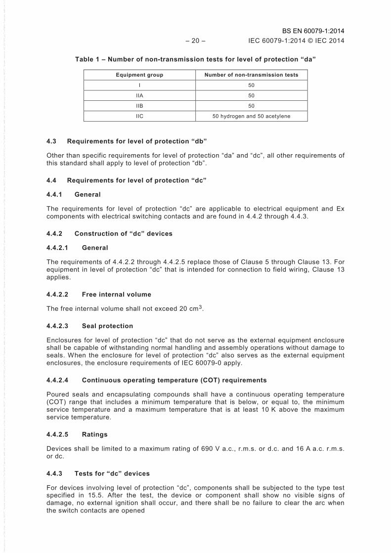
Table 1 – Number of non-transmission tests for level of protection “da”
Equipment group Number of non-transmission tests
I 50
IIA 50
IIB 50
IIC 50 hydrogen and 50 acetylene
4.3 Requirements for level of protection “db”
Other than specific requirements for level of protection “da” and “dc”, all other requirements of this standard shall apply to level of protection “db”.
4.4 Requirements for level of protection “dc”
4.4.1 General
The requirements for level of protection “dc” are applicable to electrical equipment and Ex components with electrical switching contacts and are found in 4.4.2 through 4.4.3.
4.4.2 Construction of “dc” devices
4.4.2.1 General
The requirements of 4.4.2.2 through 4.4.2.5 replace those of Clause 5 through Clause 13. For equipment in level of protection “dc” that is intended for connection to field wiring, Clause 13 applies.
4.4.2.2 Free internal volume
The free internal volume shall not exceed 20 cm3.
4.4.2.3 Seal protection
Enclosures for level of protection “dc” that do not serve as the external equipment enclosure shall be capable of withstanding normal handling and assembly operations without damage to seals. When the enclosure for level of protection “dc” also serves as the external equipment enclosures, the enclosure requirements of IEC 60079-0 apply.
4.4.2.4 Continuous operating temperature (COT) requirements
Poured seals and encapsulating compounds shall have a continuous operating temperature (COT) range that includes a minimum temperature that is below, or equal to, the minimum service temperature and a maximum temperature that is at least 10 K above the maximum service temperature.
4.4.2.5 Ratings
Devices shall be limited to a maximum rating of 690 V a.c., r.m.s. or d.c. and 16 A a.c. r.m.s. or dc.
4.4.3 Tests for “dc” devices
For devices involving level of protection “dc”, components shall be subjected to the type test specified in 15.5. After the test, the device or component shall show no visible signs of damage, no external ignition shall occur, and there shall be no failure to clear the arc when the switch contacts are opened
BS EN 60079-1:2014

IEC 60079-1:2014 © IEC 2014 – 21 –
5 Flameproof joints
5.1 General requirements
All flameproof joints, whether permanently closed or designed to be opened from time to time, shall comply, in the absence of pressure, with the appropriate requirements of Clause 5.
The design of joints shall be appropriate to the mechanical constraints applied to them.
The dimensions given in 5.2 to 5.5 specify the essential parameters of flamepaths. In instances where any of the following apply (for example, in order to comply with the test for non-transmission of an internal ignition):
– the minimum length of the flameproof joint as stated by the documentation is greater than the relevant minimum; or
– the maximum gap of the flameproof joint as stated by the documentation is less than the relevant maximum; or
– the minimum number of threads engaged for the flameproof joint as stated by the documentation is more than the relevant minimum;
NOTE 1 IEC 60079-0 defines the documentation as the documents that give a full and correct specification of the explosion safety aspects of the electrical equipment.
the equipment certificate number shall include the "X" suffix in accordance with the marking requirements of IEC 60079-0 and the specific conditions of use listed on the certificate and in the instructions shall detail one of the following:
– dimensions of the flameproof joints shall be detailed; or – specific drawing referenced that details the dimensions of the flameproof joints; or – specific guidance noted to contact the original manufacturer for information on the
dimensions of the flameproof joints; or – specific indication that the flameproof joints are not intended to be repaired.
NOTE 2 IEC 60079-0 permits the use of an advisory marking on the equipment as an alternative for the requirements for the “X” marking.
The surface of joints may be protected against corrosion.
Coating with paint or powder-coat finish is not permitted. Other coating material may be used if the material and application procedure have been shown not to adversely affect the flameproof properties of the joint.
Corrosion inhibiting grease, such as petrolatum or soap-thickened mineral oils, may be applied to joint surfaces before assembly. The grease, if applied, shall be of a type that does not harden because of ageing, does not contain an evaporating solvent, and does not cause corrosion of the joint surfaces. Verification of suitability shall be in accordance with the grease manufacturer's specifications.
Joint surfaces may be electroplated. The metal plating, if applied, shall be in accordance with the following:
– if not more than 0,008 mm thick, no additional consideration is necessary; – if more than 0,008 mm thick, then the maximum gap without the plating shall still be in
accordance with the applicable joint requirements, and shall be tested for flame transmission based on the gap dimension that would exist without the plating.
BS EN 60079-1:2014
– 22 – IEC 60079-1:2014 © IEC 2014
5.2 Non-threaded joints
5.2.1 Width of joints (L)
The width of joints shall not be less than the minimum values given in Tables 2 and 3.
The width of joints for cylindrical metallic parts press-fitted into the walls of a metallic flameproof enclosure of a volume not greater than 2 000 cm3 may be reduced to 5 mm, if
a) the design does not rely only on an interference fit to prevent the part being displaced during the type tests of Clause 15,
b) the assembly meets the impact test requirements of IEC 60079-0, taking the worst-case interference fit tolerances into account, and
c) the external diameter of the press-fitted part, where the width of the joint is measured, does not exceed 60 mm.
NOTE There is no prohibition of press-fit combinations of other than metallic parts into metallic flameproof enclosures. In these other combinations, the minimum width of joint requirements of Tables 2 or 3 apply.
5.2.2 Gap (i)
The gap, if one exists, between the surfaces of a joint shall nowhere exceed the maximum values given in Tables 2 and 3.
The surfaces of joints shall be such that their average roughness Ra does not exceed 6,3 µm.
NOTE Average roughness is derived from ISO 468. Determination can be made by visual comparison to a reference plate.
For flanged joints of other than quick-acting doors or covers, there shall be no intentional gap between the surfaces other than that created by the flatness tolerances of the mating parts.
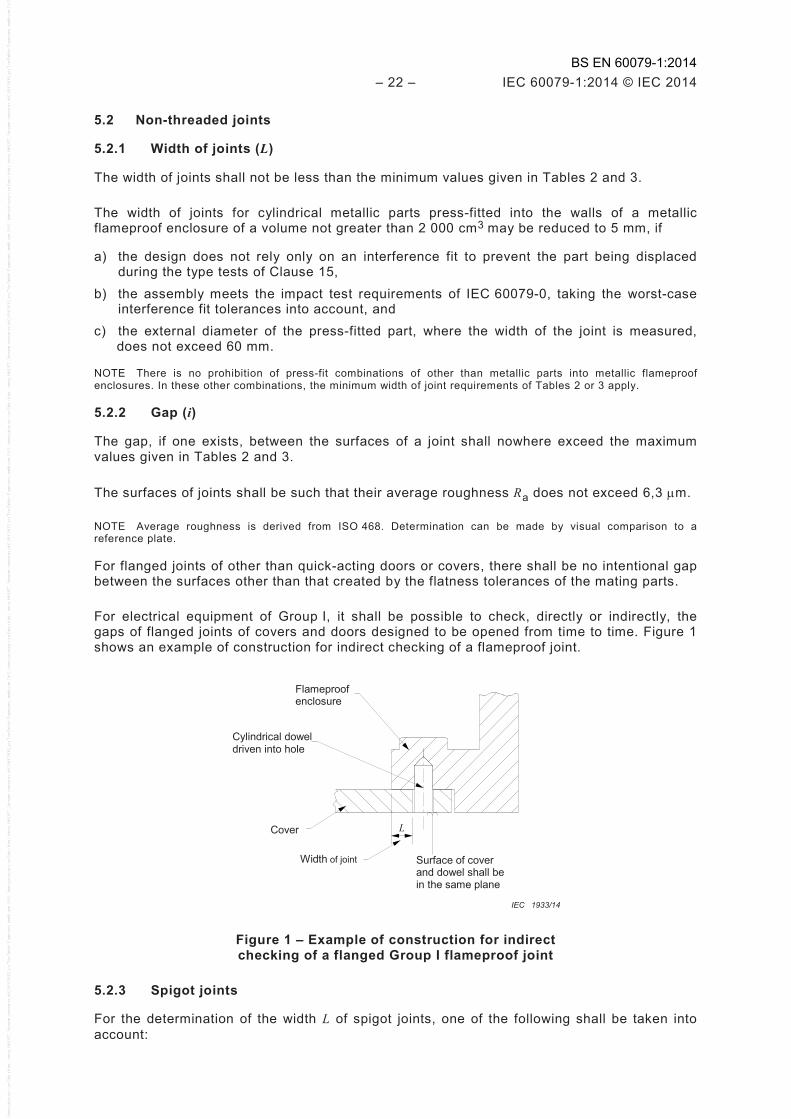
For electrical equipment of Group I, it shall be possible to check, directly or indirectly, the gaps of flanged joints of covers and doors designed to be opened from time to time. Figure 1 shows an example of construction for indirect checking of a flameproof joint.
Flameproof enclosure
Cylindrical dowel driven into hole
Surface of cover and dowel shall be in the same plane
L Cover
Width of joint
IEC 1933/14
Figure 1 – Example of construction for indirect checking of a flanged Group I flameproof joint
5.2.3 Spigot joints
For the determination of the width L of spigot joints, one of the following shall be taken into account:
BS EN 60079-1:2014
IEC 60079-1:2014 © IEC 2014 – 23 –
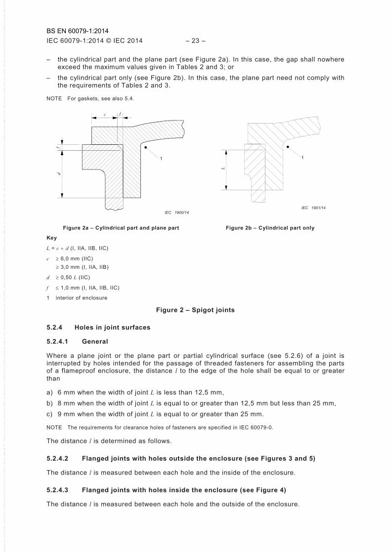
– the cylindrical part and the plane part (see Figure 2a). In this case, the gap shall nowhere exceed the maximum values given in Tables 2 and 3; or
– the cylindrical part only (see Figure 2b). In this case, the plane part need not comply with the requirements of Tables 2 and 3.
NOTE For gaskets, see also 5.4.
1
c f
f d
IEC 1900/14
1
L
IEC 1901/14
Figure 2a – Cylindrical part and plane part Figure 2b – Cylindrical part only
Key
L = c + d (I, IIA, IIB, IIC)
c ≥ 6,0 mm (IIC) ≥ 3,0 mm (I, IIA, IIB)
d ≥ 0,50 L (IIC)
f ≤ 1,0 mm (I, IIA, IIB, IIC)
1 interior of enclosure
Figure 2 – Spigot joints
5.2.4 Holes in joint surfaces
5.2.4.1 General
Where a plane joint or the plane part or partial cylindrical surface (see 5.2.6) of a joint is interrupted by holes intended for the passage of threaded fasteners for assembling the parts of a flameproof enclosure, the distance l to the edge of the hole shall be equal to or greater than
a) 6 mm when the width of joint L is less than 12,5 mm, b) 8 mm when the width of joint L is equal to or greater than 12,5 mm but less than 25 mm, c) 9 mm when the width of joint L is equal to or greater than 25 mm.
NOTE The requirements for clearance holes of fasteners are specified in IEC 60079-0.
The distance l is determined as follows.
5.2.4.2 Flanged joints with holes outside the enclosure (see Figures 3 and 5)
The distance l is measured between each hole and the inside of the enclosure.
5.2.4.3 Flanged joints with holes inside the enclosure (see Figure 4)
The distance l is measured between each hole and the outside of the enclosure.
BS EN 60079-1:2014
– 24 – IEC 60079-1:2014 © IEC 2014
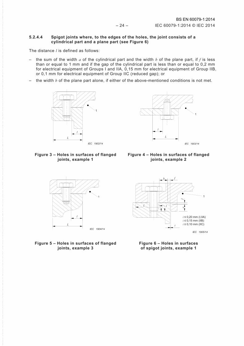
5.2.4.4 Spigot joints where, to the edges of the holes, the joint consists of a cylindrical part and a plane part (see Figure 6)
The distance l is defined as follows:
– the sum of the width a of the cylindrical part and the width b of the plane part, if f is less than or equal to 1 mm and if the gap of the cylindrical part is less than or equal to 0,2 mm for electrical equipment of Groups I and IIA, 0,15 mm for electrical equipment of Group IIB, or 0,1 mm for electrical equipment of Group IIC (reduced gap); or
– the width b of the plane part alone, if either of the above-mentioned conditions is not met.
L
1
l
IEC 1902/14
l
L
1
IEC 1903/14
Figure 3 – Holes in surfaces of flanged joints, example 1
Figure 4 – Holes in surfaces of flanged joints, example 2
L
1
l
IEC 1904/14
1
b f
L l
i
a f
i ≤ 0,20 mm (I,IIA) i ≤ 0,15 mm (IIB) i ≤ 0,10 mm (IIC)
IEC 1905/14
Figure 5 – Holes in surfaces of flanged joints, example 3
Figure 6 – Holes in surfaces of spigot joints, example 1
BS EN 60079-1:2014
IEC 60079-1:2014 © IEC 2014 – 25 –
1 L
l
IEC 1906/14
l
1
L
IEC 1907/14
Figure 7 – Holes in surfaces of spigot joints, example 2
Figure 8 – Holes in surfaces of spigot joints, example 3
Key
1 interior of enclosure
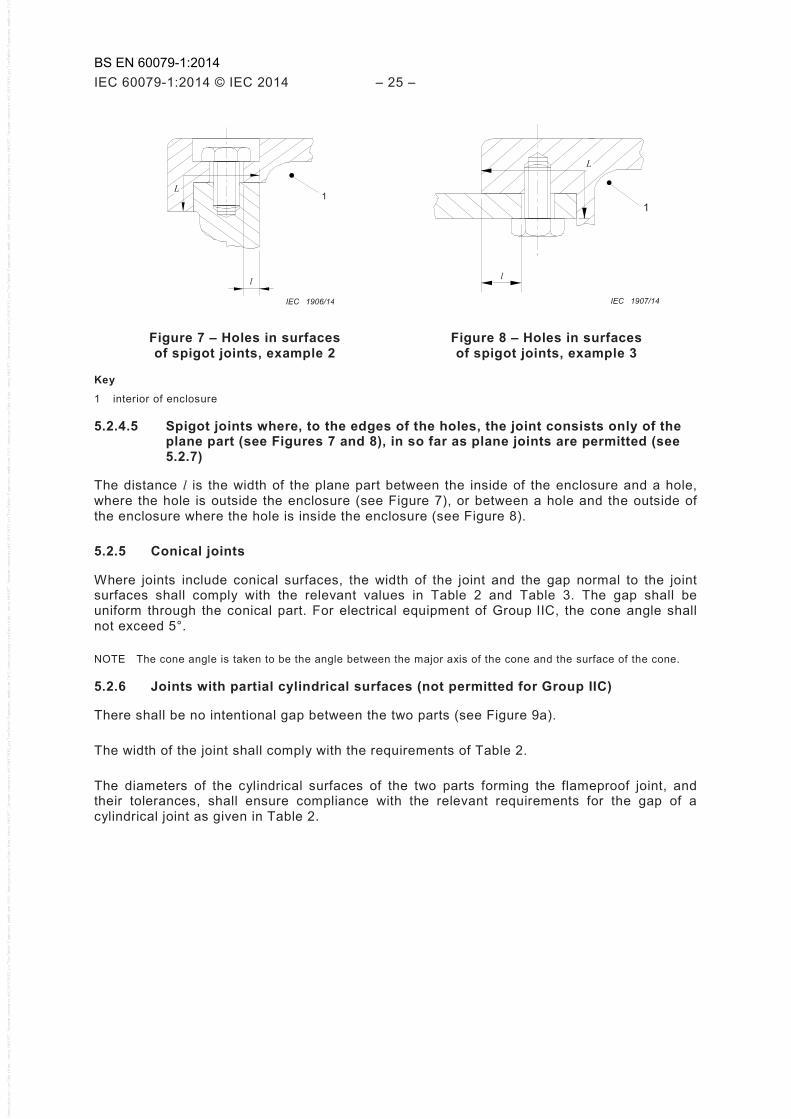
5.2.4.5 Spigot joints where, to the edges of the holes, the joint consists only of the plane part (see Figures 7 and 8), in so far as plane joints are permitted (see 5.2.7)
The distance l is the width of the plane part between the inside of the enclosure and a hole, where the hole is outside the enclosure (see Figure 7), or between a hole and the outside of the enclosure where the hole is inside the enclosure (see Figure 8).
5.2.5 Conical joints
Where joints include conical surfaces, the width of the joint and the gap normal to the joint surfaces shall comply with the relevant values in Table 2 and Table 3. The gap shall be uniform through the conical part. For electrical equipment of Group IIC, the cone angle shall not exceed 5°.
NOTE The cone angle is taken to be the angle between the major axis of the cone and the surface of the cone.
5.2.6 Joints with partial cylindrical surfaces (not permitted for Group IIC)
There shall be no intentional gap between the two parts (see Figure 9a).
The width of the joint shall comply with the requirements of Table 2.
The diameters of the cylindrical surfaces of the two parts forming the flameproof joint, and their tolerances, shall ensure compliance with the relevant requirements for the gap of a cylindrical joint as given in Table 2.
BS EN 60079-1:2014

– 26 – IEC 60079-1:2014 © IEC 2014
Figure 9a – Example of a joint with partial cylindrical surfaces
Figure 9b – Example of serrated joint
Figure 9 – Examples of joint constructions
5.2.7 Flanged joints for acetylene atmospheres
Flanged joints are only permitted for electrical equipment of Group IIC intended for use in explosive gas atmospheres containing acetylene provided all of the following conditions are met:
– gap i ≤ 0,04 mm;
– width L ≥ 9,5 mm; and
– volume ≤ 500 cm3.
5.2.8 Serrated joints
Serrated joints need not comply with the requirements of Tables 2 and 3 but shall have
– at least five fully engaged serrations, – a pitch greater than or equal to 1,25 mm, and
– an included angle of 60° (± 5°).
Serrated joints shall only be used for joints that are fixed in place during operation.
Serrated joints shall satisfy the test requirements of 15.3, with a) the test gap, iE, between the mating serrations as specified in 15.3, based on the manufacturer’s maximum constructional gap, iC, and b) the test length reduced to Y / 1,5.
IEC 1908/14
T α
Y
Y ≥ 5T Test length = Y
1,5 T ≥ 1,25mm α = 60°(±5°)
IEC 1909/14
BS EN 60079-1:2014
IEC 60079-1:2014 © IEC 2014 – 27 –
If the manufacturer’s maximum constructional gap is different to that shown in Tables 2 or 3 for a flanged joint of the same length (determined by multiplying the pitch by the number of serrations), the “conditions of use” requirements of 5.1 apply.
See Figure 9b.
5.2.9 Multi-step joints
A multi-step joint shall consist of not less than 3 adjacent segments where the path changes direction not less than two times by 90° ± 5°.
Multi-step joints need not comply with the requirements of Tables 2 or 3 but shall satisfy the test requirements of 15.3 with the test length of each segment reduced to not more than 75 % of the manufacturer’s specified design minimum lengths.
For flameproof enclosures that incorporate multi-step joints, the equipment certificate number shall include the "X" suffix in accordance with the marking requirements of IEC 60079-0 and the specific conditions of use listed on the certificate shall detail one of the following:
– dimensions of the flameproof joints shall be detailed; or – specific drawing referenced that details the dimensions of the flameproof joints; or – specific guidance noted to contact the original manufacturer for information on the
dimensions of the flameproof joints; or – specific indication that the flameproof joints are not intended to be repaired.
NOTE 1 IEC 60079-0 permits the use of an advisory marking on the equipment as an alternative for the requirements for the “X” marking.
NOTE 2 Multi-step joints are distinct from labyrinth joints on rotating shafts as addressed in this standard (see 8.1.3).
BS EN 60079-1:2014
– 28 – IEC 60079-1:2014 © IEC 2014
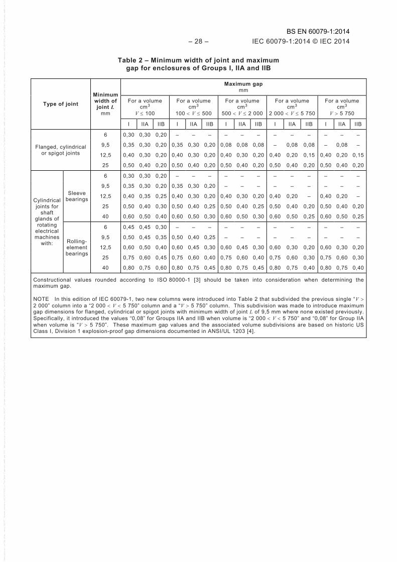
Table 2 – Minimum width of joint and maximum gap for enclosures of Groups I, IIA and IIB
Type of joint Minimum width of joint L
mm
Maximum gap mm
For a volume cm3
V ≤ 100
For a volume cm3
100 < V ≤ 500
For a volume cm3
500 < V ≤ 2 000
For a volume cm3
2 000 < V ≤ 5 750
For a volume cm3
V > 5 750
I IIA IIB I IIA IIB I IIA IIB I IIA IIB I IIA IIB
Flanged, cylindrical or spigot joints
6 0,30 0,30 0,20 – – – – – – – – – – – –
9,5 0,35 0,30 0,20 0,35 0,30 0,20 0,08 0,08 0,08 – 0,08 0,08 – 0,08 –
12,5 0,40 0,30 0,20 0,40 0,30 0,20 0,40 0,30 0,20 0,40 0,20 0,15 0,40 0,20 0,15
25 0,50 0,40 0,20 0,50 0,40 0,20 0,50 0,40 0,20 0,50 0,40 0,20 0,50 0,40 0,20
Cylindrical joints for
shaft glands of rotating
electrical machines
with:
Sleeve bearings
6 0,30 0,30 0,20 – – – – – – – – – – – –
9,5 0,35 0,30 0,20 0,35 0,30 0,20 – – – – – – – – –
12,5 0,40 0,35 0,25 0,40 0,30 0,20 0,40 0,30 0,20 0,40 0,20 – 0,40 0,20 –
25 0,50 0,40 0,30 0,50 0,40 0,25 0,50 0,40 0,25 0,50 0,40 0,20 0,50 0,40 0,20
40 0,60 0,50 0,40 0,60 0,50 0,30 0,60 0,50 0,30 0,60 0,50 0,25 0,60 0,50 0,25
Rolling-element bearings
6 0,45 0,45 0,30 – – – – – – – – – – – –
9,5 0,50 0,45 0,35 0,50 0,40 0,25 – – – – – – – – –
12,5 0,60 0,50 0,40 0,60 0,45 0,30 0,60 0,45 0,30 0,60 0,30 0,20 0,60 0,30 0,20
25 0,75 0,60 0,45 0,75 0,60 0,40 0,75 0,60 0,40 0,75 0,60 0,30 0,75 0,60 0,30
40 0,80 0,75 0,60 0,80 0,75 0,45 0,80 0,75 0,45 0,80 0,75 0,40 0,80 0,75 0,40
Constructional values rounded according to ISO 80000-1 [3] should be taken into consideration when determining the maximum gap.
NOTE In this edition of IEC 60079-1, two new columns were introduced into Table 2 that subdivided the previous single “V > 2 000” column into a “2 000 < V < 5 750” column and a “V > 5 750” column. This subdivision was made to introduce maximum gap dimensions for flanged, cylindrical or spigot joints with minimum width of joint L of 9,5 mm where none existed previously. Specifically, it introduced the values “0,08” for Groups IIA and IIB when volume is “2 000 < V < 5 750” and “0,08” for Group IIA when volume is “V > 5 750”. These maximum gap values and the associated volume subdivisions are based on historic US Class I, Division 1 explosion-proof gap dimensions documented in ANSI/UL 1203 [4].
BS EN 60079-1:2014
IEC 60079-1:2014 © IEC 2014 – 29 –
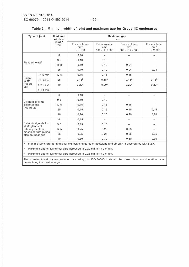
Table 3 – Minimum width of joint and maximum gap for Group IIC enclosures
Type of joint Minimum width of joint L
mm
Maximum gap mm
For a volume cm3
V ≤ 100
For a volume cm3
100 < V ≤ 500
For a volume cm3
500 < V ≤ 2 000
For a volume cm3
V > 2 000
Flanged jointsa
6 0,10 – – –
9,5 0,10 0,10 – –
15,8 0,10 0,10 0,04 –
25 0,10 0,10 0,04 0,04
Spigot joints (Figure 2a)
c ≥ 6 mm 12,5 0,15 0,15 0,15 –
d ≥ 0,5 L 25 0,18b 0,18b 0,18b 0,18b
L = c + d 40 0,20c 0,20c 0,20c 0,20c
f ≤ 1 mm
Cylindrical joints Spigot joints (Figure 2b)
6 0,10 – – –
9,5 0,10 0,10 – –
12,5 0,15 0,15 0,15 –
25 0,15 0,15 0,15 0,15
40 0,20 0,20 0,20 0,20
Cylindrical joints for shaft glands of rotating electrical machines with rolling element bearings
6 0,15 – – –
9,5 0,15 0,15 – –
12,5 0,25 0,25 0,25 –
25 0,25 0,25 0,25 0,25
40 0,30 0,30 0,30 0,30 a Flanged joints are permitted for explosive mixtures of acetylene and air only in accordance with 5.2.7. b Maximum gap of cylindrical part increased to 0,20 mm if f < 0,5 mm. c Maximum gap of cylindrical part increased to 0,25 mm if f < 0,5 mm.
The constructional values rounded according to ISO 80000-1 should be taken into consideration when determining the maximum gap.
BS EN 60079-1:2014

– 30 – IEC 60079-1:2014 © IEC 2014
5.3 Threaded joints
Threaded joints shall comply with the requirements given in Tables 4 or 5.
Table 4 – Cylindrical threaded joints
Pitch ≥ 0,7 mm a
Thread form and quality of fit Medium or fine tolerance quality according to ISO 965-1 and ISO 965-3b
Threads engaged ≥ 5
Depth of engagement
Volume ≤ 100 cm3 ≥ 5 mm
Volume >100 cm3 ≥ 8 mm a Where the pitch exceeds 2 mm, special manufacturing precautions may be necessary (for example, more
threads engaged) to ensure that the electrical equipment can pass the test for non-transmission of an internal ignition which is prescribed in 15.3.
b Cylindrical threaded joints which do not conform with ISO 965-1 and ISO 965-3 in respect of thread form or quality of fit are permitted if the test for non-transmission of an internal ignition, prescribed in 15.3, is passed, when the width of the threaded joint specified by the manufacturer is reduced by the amount specified in Table 9.
Table 5 – Taper threaded joints a, c
Threads provided on each part ≥ 5 b a Internal and external thread shall have the same nominal size. b Threads shall conform to the NPT requirements of ANSI/ASME B1.20.1 and shall be made-up wrench tight.
External threaded parts shall be provided with:
1) an effective thread length not less than the “L2” dimension; and
2) if a shoulder is provided, a length not less than the “L4” dimension between the face of the shoulder and end of the thread.
Internal threads shall gauge at “flush” to “2 turns large” using an L1 plug-gauge. c Where the tapered threaded joint consists of both the internal and external threaded parts with at least 4,5
fully engaged threads, the requirements of footnote b in this table need not be applied.
NOTE See Annex C for tapered thread requirements applicable to flameproof entry devices.
5.4 Gaskets (including O-rings)
If a gasket of compressible or elastic material is used, for example, to protect against the ingress of moisture or dust or against leakage of a liquid, it shall be applied as a supplement, that is to say neither be taken into account in the determination of the width of the flameproof joint nor interrupt it.
The gasket shall then be mounted so that
a) the permissible gap and width of flanged joints or the plane part of a spigot joint are maintained, and
b) the minimum width of joint of a cylindrical joint or the cylindrical part of a spigot joint are maintained before and after compression.
These requirements do not apply to cable glands (see 13.4) or to joints which contain a sealing gasket of metal or of a non-flammable compressible material with a metallic sheath. Such a sealing gasket contributes to the explosion protection, and in this case the gap between each surface of the plane part shall be measured after compression. The minimum width of the cylindrical part shall be maintained before and after compression.
BS EN 60079-1:2014
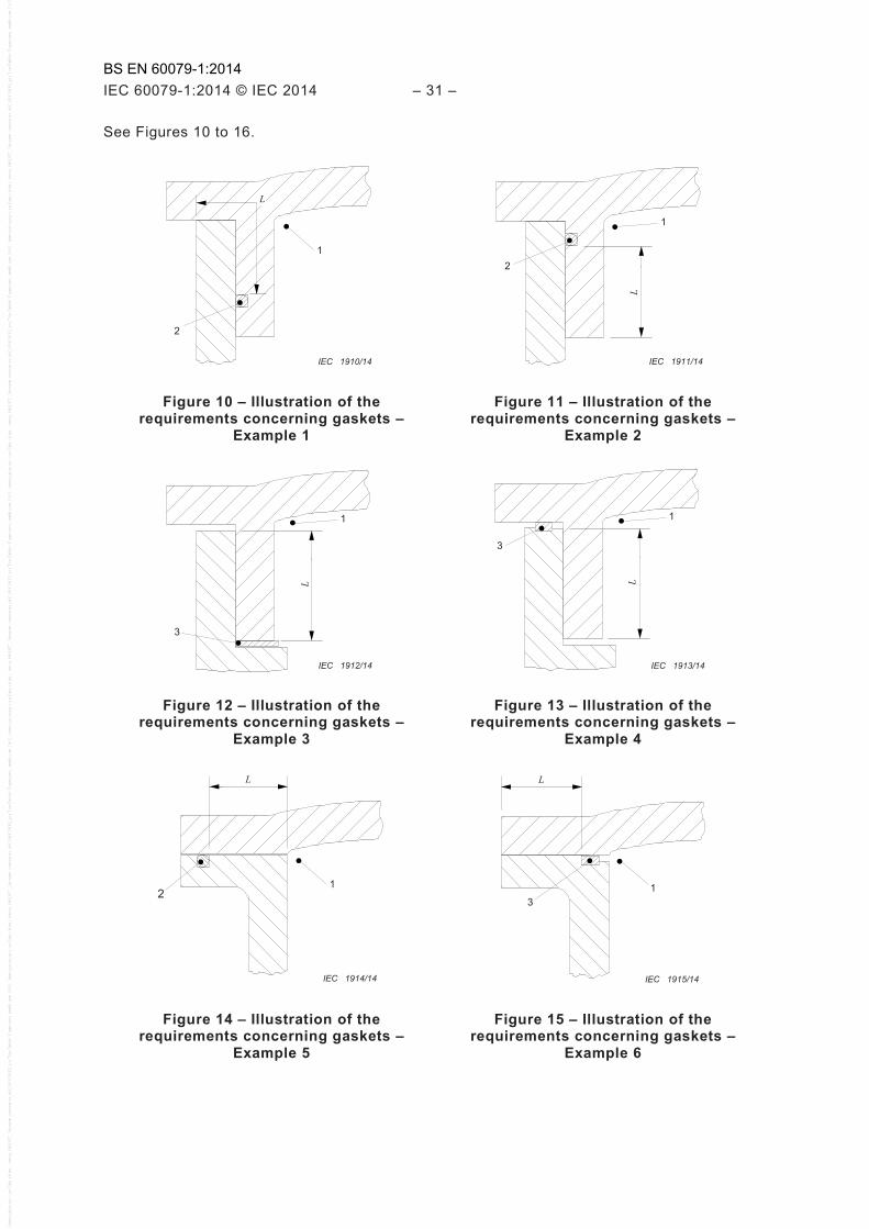
IEC 60079-1:2014 © IEC 2014 – 31 –
See Figures 10 to 16.
1
2
L
IEC 1910/14
1
2
L
IEC 1911/14
Figure 10 – Illustration of the requirements concerning gaskets –
Example 1
Figure 11 – Illustration of the requirements concerning gaskets –
Example 2
1
3
L
IEC 1912/14
1
3
L
IEC 1913/14
Figure 12 – Illustration of the requirements concerning gaskets –
Example 3
Figure 13 – Illustration of the requirements concerning gaskets –
Example 4
1 2
L
IEC 1914/14
1
L
3
IEC 1915/14
Figure 14 – Illustration of the requirements concerning gaskets –
Example 5
Figure 15 – Illustration of the requirements concerning gaskets –
Example 6
BS EN 60079-1:2014
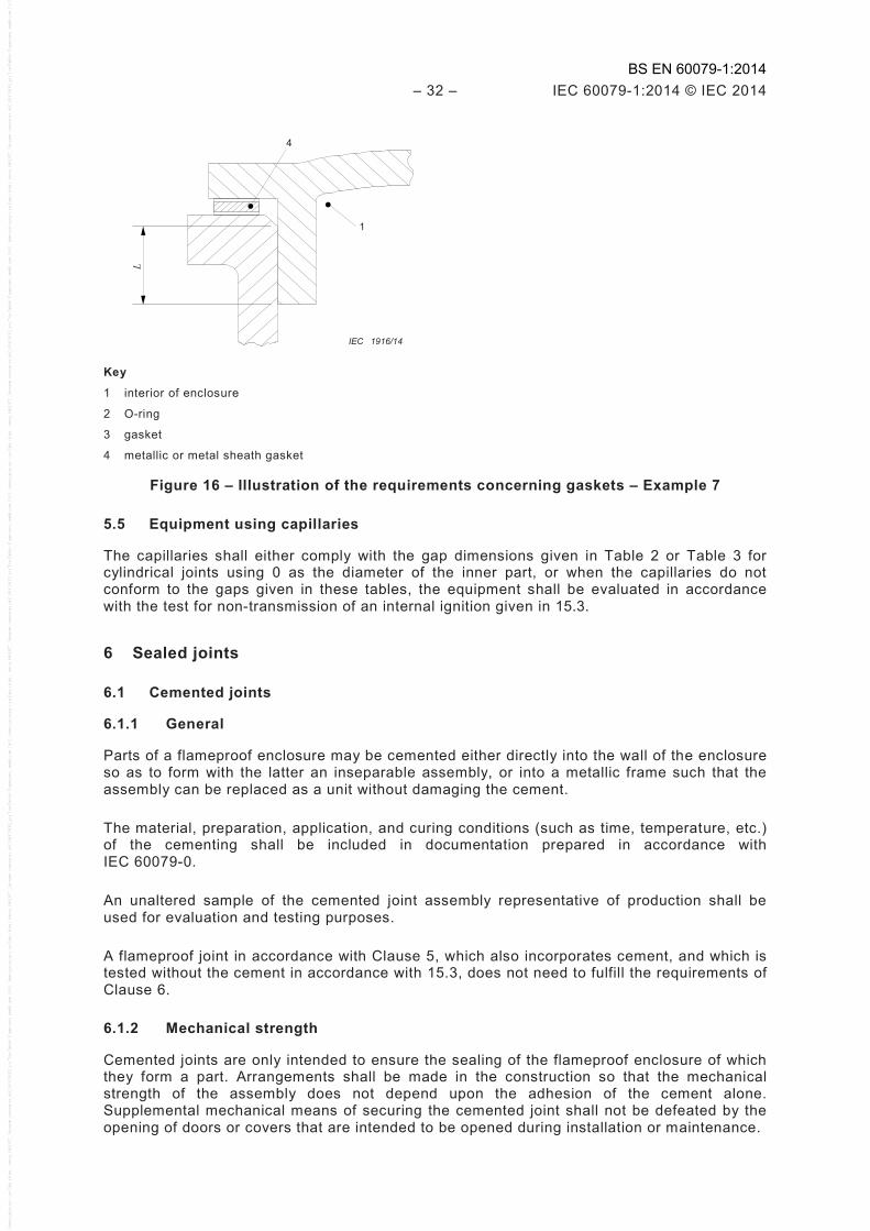
– 32 – IEC 60079-1:2014 © IEC 2014
1
4 L
IEC 1916/14
Key
1 interior of enclosure
2 O-ring
3 gasket
4 metallic or metal sheath gasket
Figure 16 – Illustration of the requirements concerning gaskets – Example 7
5.5 Equipment using capillaries
The capillaries shall either comply with the gap dimensions given in Table 2 or Table 3 for cylindrical joints using 0 as the diameter of the inner part, or when the capillaries do not conform to the gaps given in these tables, the equipment shall be evaluated in accordance with the test for non-transmission of an internal ignition given in 15.3.
6 Sealed joints
6.1 Cemented joints
6.1.1 General
Parts of a flameproof enclosure may be cemented either directly into the wall of the enclosure so as to form with the latter an inseparable assembly, or into a metallic frame such that the assembly can be replaced as a unit without damaging the cement.
The material, preparation, application, and curing conditions (such as time, temperature, etc.) of the cementing shall be included in documentation prepared in accordance with IEC 60079-0.
An unaltered sample of the cemented joint assembly representative of production shall be used for evaluation and testing purposes.
A flameproof joint in accordance with Clause 5, which also incorporates cement, and which is tested without the cement in accordance with 15.3, does not need to fulfill the requirements of Clause 6.
6.1.2 Mechanical strength
Cemented joints are only intended to ensure the sealing of the flameproof enclosure of which they form a part. Arrangements shall be made in the construction so that the mechanical strength of the assembly does not depend upon the adhesion of the cement alone. Supplemental mechanical means of securing the cemented joint shall not be defeated by the opening of doors or covers that are intended to be opened during installation or maintenance.
BS EN 60079-1:2014

IEC 60079-1:2014 © IEC 2014 – 33 –
Cemented joints shall be subjected to the following tests:
a) Two samples representative of production shall be subjected to an overpressure test with water in accordance with 15.2.3.2. The test is considered satisfactory if blotting paper, placed under each sample under test, is free from any trace of leakage.
b) Either the same two samples from a) above, or a separate set of samples, shall be subjected to the tests of enclosures in IEC 60079-0, as applicable. Subsequent to this conditioning, the samples shall be subjected to an overpressure test with water in accordance with 15.2.3.2. The test is considered satisfactory if blotting paper, placed under each sample under test, is free from any trace of leakage.
NOTE The tests of enclosures in IEC 60079-0 permit the tests to be conducted on either a set of two samples or a set of four samples, with the difference being the number of tests conducted on each sample.
If there is any leakage on the blotting paper as a result of the test on the samples from 6.1.2 b), then the cemented joint for one sample that leaks after being subjected to the tests of enclosures and hydraulic pressure testing shall be subjected to the following tests:
– the flame erosion test in 19.4 but with no modifications to the cemented joints of the test samples, followed by
– the test for non-transmission in 15.3.2.1, or the test for non-transmission in 15.3.3.3 or 15.3.3.4, as applicable for the equipment group, with no further modifications to the cemented joints of the test sample.
The cemented joint is judged satisfactory if this test for non-transmission is satisfactory.
Routine overpressure testing of cemented joints (per Clause 16) shall be performed whenever 1,5 times or 3 times the reference pressure is necessary to comply with 6.1.2.
6.1.3 Width of cemented joints
The shortest path through a cemented joint from the inside to the outside of a flameproof enclosure of volume V shall be
≥ 3 mm if V ≤ 10 cm3
≥ 6 mm if 10 cm3 < V ≤ 100 cm3
≥ 10 mm if V > 100 cm3
6.2 Fused glass joints
6.2.1 General
Fused glass joints are glass-to-metal joints formed by the application of molten glass into a metal frame that results in either a chemical or physical bond between the glass and the metal frame.
6.2.2 Width of fused glass joints
The path through a fused glass joint from the inside to the outside of a flameproof enclosure shall be ≥ 3 mm.
7 Operating rods
Where an operating rod passes through the wall of a flameproof enclosure, the following requirements shall be met:
– if the diameter of the operating rod exceeds the minimum width of the joint specified in Tables 2 and 3, the width of the joint shall be at least equal to this diameter but without, however, having to exceed 25 mm;
BS EN 60079-1:2014
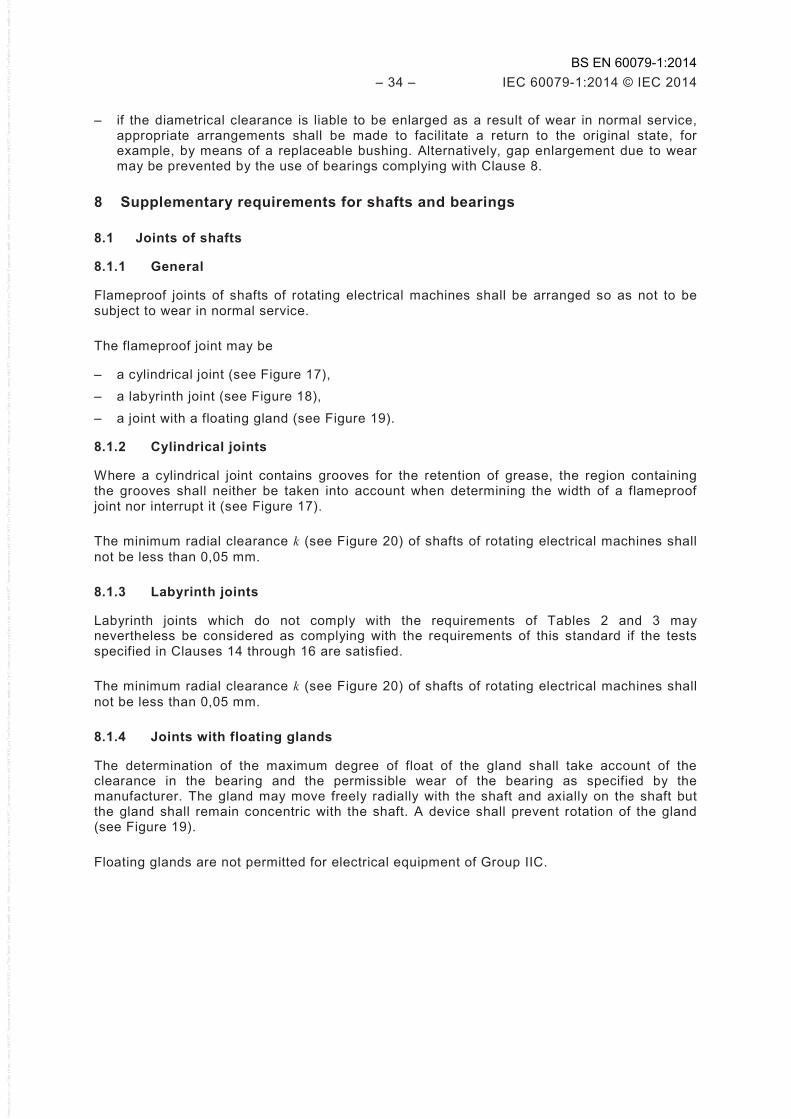
– 34 – IEC 60079-1:2014 © IEC 2014
– if the diametrical clearance is liable to be enlarged as a result of wear in normal service, appropriate arrangements shall be made to facilitate a return to the original state, for example, by means of a replaceable bushing. Alternatively, gap enlargement due to wear may be prevented by the use of bearings complying with Clause 8.
8 Supplementary requirements for shafts and bearings
8.1 Joints of shafts
8.1.1 General
Flameproof joints of shafts of rotating electrical machines shall be arranged so as not to be subject to wear in normal service.
The flameproof joint may be
– a cylindrical joint (see Figure 17), – a labyrinth joint (see Figure 18), – a joint with a floating gland (see Figure 19).
8.1.2 Cylindrical joints
Where a cylindrical joint contains grooves for the retention of grease, the region containing the grooves shall neither be taken into account when determining the width of a flameproof joint nor interrupt it (see Figure 17).
The minimum radial clearance k (see Figure 20) of shafts of rotating electrical machines shall not be less than 0,05 mm.
8.1.3 Labyrinth joints
Labyrinth joints which do not comply with the requirements of Tables 2 and 3 may nevertheless be considered as complying with the requirements of this standard if the tests specified in Clauses 14 through 16 are satisfied.
The minimum radial clearance k (see Figure 20) of shafts of rotating electrical machines shall not be less than 0,05 mm.
8.1.4 Joints with floating glands
The determination of the maximum degree of float of the gland shall take account of the clearance in the bearing and the permissible wear of the bearing as specified by the manufacturer. The gland may move freely radially with the shaft and axially on the shaft but the gland shall remain concentric with the shaft. A device shall prevent rotation of the gland (see Figure 19).
Floating glands are not permitted for electrical equipment of Group IIC.
BS EN 60079-1:2014
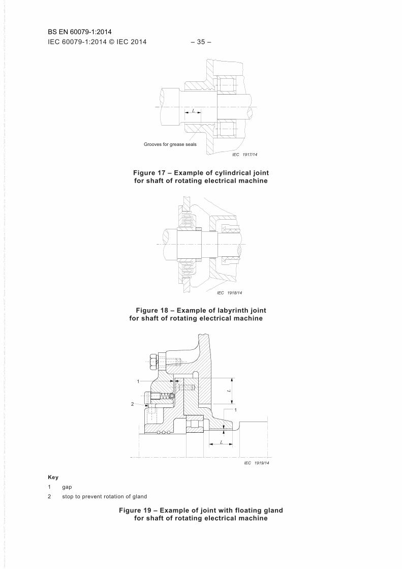
IEC 60079-1:2014 © IEC 2014 – 35 –
L
Grooves for grease seals
IEC 1917/14
Figure 17 – Example of cylindrical joint for shaft of rotating electrical machine
IEC 1918/14
Figure 18 – Example of labyrinth joint for shaft of rotating electrical machine
1
2 1
L
L
IEC 1919/14
Key
1 gap
2 stop to prevent rotation of gland
Figure 19 – Example of joint with floating gland for shaft of rotating electrical machine
BS EN 60079-1:2014
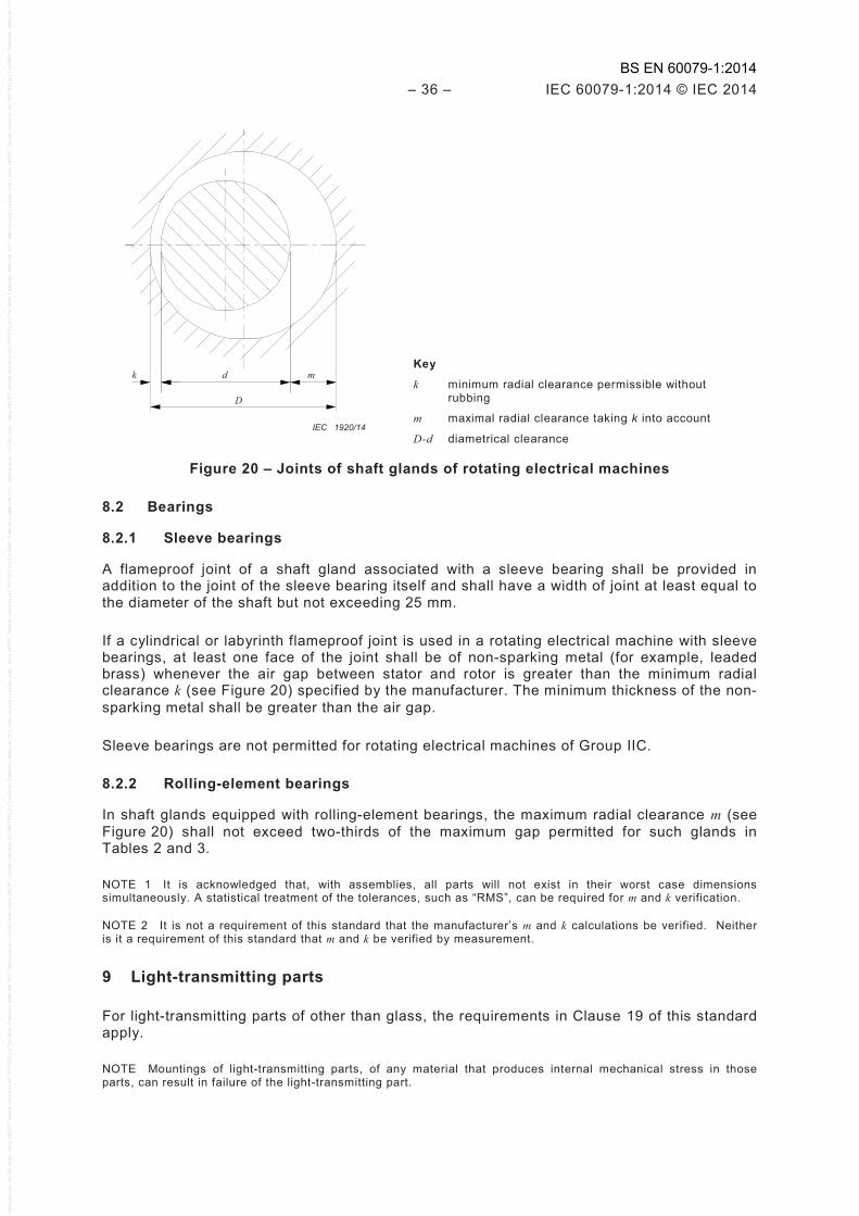
– 36 – IEC 60079-1:2014 © IEC 2014
d k m
D
IEC 1920/14
Key
k minimum radial clearance permissible without rubbing
m maximal radial clearance taking k into account
D-d diametrical clearance
Figure 20 – Joints of shaft glands of rotating electrical machines
8.2 Bearings
8.2.1 Sleeve bearings
A flameproof joint of a shaft gland associated with a sleeve bearing shall be provided in addition to the joint of the sleeve bearing itself and shall have a width of joint at least equal to the diameter of the shaft but not exceeding 25 mm.
If a cylindrical or labyrinth flameproof joint is used in a rotating electrical machine with sleeve bearings, at least one face of the joint shall be of non-sparking metal (for example, leaded brass) whenever the air gap between stator and rotor is greater than the minimum radial clearance k (see Figure 20) specified by the manufacturer. The minimum thickness of the non-sparking metal shall be greater than the air gap.
Sleeve bearings are not permitted for rotating electrical machines of Group IIC.
8.2.2 Rolling-element bearings
In shaft glands equipped with rolling-element bearings, the maximum radial clearance m (see Figure 20) shall not exceed two-thirds of the maximum gap permitted for such glands in Tables 2 and 3.
NOTE 1 It is acknowledged that, with assemblies, all parts will not exist in their worst case dimensions simultaneously. A statistical treatment of the tolerances, such as “RMS”, can be required for m and k verification.
NOTE 2 It is not a requirement of this standard that the manufacturer’s m and k calculations be verified. Neither is it a requirement of this standard that m and k be verified by measurement.
9 Light-transmitting parts
For light-transmitting parts of other than glass, the requirements in Clause 19 of this standard apply.
NOTE Mountings of light-transmitting parts, of any material that produces internal mechanical stress in those parts, can result in failure of the light-transmitting part.
BS EN 60079-1:2014

IEC 60079-1:2014 © IEC 2014 – 37 –
10 Breathing and draining devices which form part of a flameproof enclosure
10.1 General
Breathing and draining devices shall incorporate permeable elements which can withstand the pressure created by an internal explosion in the enclosure to which they are fitted, and which shall prevent the transmission of the explosion to the explosive atmosphere surrounding the enclosure.
They shall also withstand the dynamic effects of explosions within the flameproof enclosure without permanent distortion or damage which would impair their flame-arresting properties. They are not intended to withstand continuous burning on their surfaces.
These requirements apply equally to devices for the transmission of sound but do not cover devices for
– relief of pressure in the event of internal explosion, – use with pressure lines containing gas which is capable of forming an explosive mixture
with air and is at a pressure in excess of 1,1 times atmospheric pressure.
10.2 Openings for breathing or draining
The openings for breathing or draining shall not be produced by deliberate enlargement of gaps of flanged joints.
NOTE Environmental contaminants (such as from the accumulation of dust or paint) can cause breathing and draining devices to become inoperative in service.
10.3 Composition limits
The composition limits of the materials used in the device shall be specified either directly or by reference to an existing applicable specification.
The elements of breathing or draining devices for use in an explosive gas atmosphere containing acetylene shall comprise not more than 60 % of copper by mass to limit acetylide formation.
10.4 Dimensions
The dimensions of the breathing and draining devices and their component parts shall be specified.
10.5 Elements with measurable paths
Interstices and measurable lengths of path need not comply with the values given in Tables 2 and 3, provided that the elements pass the tests of Clauses 14 through 16.
Additional requirements for crimped ribbon elements and multiple screen elements are given in Annex A.
10.6 Elements with non-measurable paths
Where the paths through the elements are not measurable (for example, sintered metal elements), the element shall comply with the relevant requirements of Annex B.
The elements are classified according to their density as well as their pore size in accordance with the standard methods for the particular material and the particular manufacturing methods (see Annex B).
BS EN 60079-1:2014
– 38 – IEC 60079-1:2014 © IEC 2014
10.7 Removable devices
10.7.1 General
If a device can be dismantled, it shall be designed to avoid reduction or enlargement of the openings during re-assembly.
10.7.2 Mounting arrangements of the elements
The breathing and draining elements shall be sintered, or fixed by other suitable methods:
– either directly into the enclosure to form an integral part of the enclosure; or – in a suitable mounting component, which is clamped or screwed into the enclosure so that
it is replaceable as a unit.
Alternatively, the element can be mounted, for example press-fitted in accordance with 5.2.1, so as to form a flameproof joint. In this case, the appropriate requirements of Clause 5 shall be applied, with the exception that the surface roughness of the element need not comply with 5.2.2, if the element arrangement passes the type test in Clauses 14 through 16.
If necessary, a clamping ring or similar means can be used to maintain the integrity of the enclosure. The breathing or draining element can be mounted
– either from within, in which case the accessibility of screws and clamping ring shall be possible only from the inside; or
– from outside the enclosure, in which case the fasteners shall comply with Clause 11.
10.8 Mechanical strength
The device and its guard, if any, shall, when mounted normally, pass the test for resistance to impact of IEC 60079-0.
10.9 Breathing devices and draining devices when used as Ex components
10.9.1 General
In addition to 10.1 through 10.7 inclusive, the following requirements shall apply to breathing and draining devices which are evaluated as Ex components.
10.9.2 Mounting arrangements of the elements and components
The breathing and draining elements shall be sintered or cemented in accordance with Clause 6, or fixed by other methods into a suitable mounting part to form the mounting component.
The mounting component is secured by clamping or by fasteners or screwed into the enclosure as a replaceable unit complying with the relevant requirements of Clauses 5 and 6 and, where appropriate, Clause 11.
10.9.3 Type tests for breathing and draining devices used as Ex components
10.9.3.1 General
Attachment of the sample device under test shall be made on the end of the test rig enclosure in the same manner as it would normally be mounted on a flameproof enclosure. The test shall be performed on the sample after the impact test of 10.8 and in accordance with 10.9.3.2 to 10.9.3.4.
The impact test may be performed on the sample, separate from the test enclosure, when it is mounted on a plate that forms the end part of the test rig enclosure.
BS EN 60079-1:2014

IEC 60079-1:2014 © IEC 2014 – 39 –
For devices with non-measurable paths, the maximum bubble test pore size of the sample shall be not less than 85 % of the specified maximum bubble test pore size. See B.1.2.
10.9.3.2 Thermal tests
10.9.3.2.1 General
After the bubble test in 10.9.3, breathing and draining devices as Ex components shall be subjected to the thermal tests based on the maximum intended flameproof enclosure volume, but no less than the volume of the test rig in Figure 21.
NOTE When using the test rig in Figure 21, the maximum volume is approximately 2,5 l.
Breathing and draining devices intended for multiple use in any single flameproof enclosure shall be tested additionally with the enclosure.
10.9.3.2.2 Test procedure
For enclosure volumes of less than or equal to 2,5 l, the test rig assembly with all four sections, as shown in Figure 21, shall be used, and the test procedure shall be carried out as follows:
a) the position of the ignition source shall be at the enclosure inlet and 50 mm from the inside of the end-plate housing the device and the results observed;
b) the test mixtures shall be as for 15.4.3.1, as appropriate; c) the temperature of the external surface of the device shall be monitored during tests; d) any device shall be operated as specified by the manufacturer's documentation. After
each of five tests, the explosive mixture shall be maintained external to the device for a sufficient time to allow any continuous burning on the face of the device to become evident, for at least 10 min, so as to increase the temperature of the external surface of the device or to make temperature transfer to the outer face possible; and
NOTE The temperature of the external surface after the 10 min test period is used in determining the temperature class in accordance with 10.9.3.3.3.
e) the tests shall be carried out five times for each gas mixture for the gas groups in which the device is intended for use.
174 500 500 500 500
Section 1 Section 2 Section 3 Section 4 Base section with:
∅40 (internal)
∅75 (internal) IG
Exh.
TS PT
IG
IG
I
IEC 1921/14
Key
TS test sample position
I inlet
Exh. exhaust outlet
IG ignition source
PT pressure transducer
Figure 21 – Component test rig for breathing and draining devices
BS EN 60079-1:2014
– 40 – IEC 60079-1:2014 © IEC 2014
For enclosure volumes of greater than 2,5 l, a representative enclosure of the intended volume shall be used, and the test procedure shall be carried out as follows:
1) the test mixtures shall be as for 15.4.3.1, as appropriate; 2) the temperature of the external surface of the device shall be monitored during tests; 3) any device shall be operated as specified by the manufacturer's documentation. After
each of five tests, the explosive mixture shall be maintained external to the device for a sufficient time to allow any continuous burning on the face of the device to become evident, for at least 10 min, so as to increase the temperature of the external surface of the device or to make temperature transfer to the outer face possible; and
4) the tests shall be carried out five times for each gas mixture for the gas groups in which the device is intended for use.
10.9.3.2.3 Acceptance criteria
During the thermal tests, no flame transmission shall occur and no continuous burning shall be observed. The device shall show no evidence of thermal or mechanical damage or deformation which could affect its flame-arresting properties.
The measured external surface temperature rise of the device shall be multiplied by a safety factor of 1,2 and added to the maximum service temperature of the device for the determination of the temperature class of the electrical equipment.
NOTE Breathing and draining devices which fail any of the tests of 10.9 are excluded from evaluation as a component device. However, when used as an integral part of a flameproof enclosure, they are tested with the specific enclosure in accordance with 15.4.
10.9.3.3 Test for non-transmission of an internal ignition
10.9.3.3.1 General
After the bubble test in 10.9.3, this test shall be carried out on a standard test rig, as illustrated in Figure 21, and made in accordance with 15.4.4, with the following additions and modifications.
10.9.3.3.2 Test procedure
The position of the ignition source shall be as shown in Figure 21:
a) at the inlet end; and b) at 50 mm from the inside of the end-plate housing the device.
For the purposes of the test, the test rig shall be assembled for each gas group, in accordance with Figure 21, and have the following number of sections:
– Group I and Group IIA: one section of test rig assembly; – Group IIB and Group IIC: four sections of test rig assembly.
The gas mixture within the test rig enclosure shall be ignited and the tests shall be made five times at each ignition point.
For breathing and draining devices of Groups I, IIA and IIB having either measurable paths or non-measurable paths, the non-transmission test of 15.3.2 shall be applied.
For breathing and draining devices of Group IIC with measurable paths, the non-transmission test of 15.3.3 and either 15.4.4.3.2 or 15.4.4.3.3 shall be applied.
For breathing or draining devices of Group IIC with non-measurable paths, 15.4.4.3.2 (method A) or 15.4.4.3.3 (method B) shall be applied.
BS EN 60079-1:2014

IEC 60079-1:2014 © IEC 2014 – 41 –
10.9.3.3.3 Acceptance criteria
During the test, no ignition shall be transmitted to the surrounding test chamber.
10.9.3.4 Test of the ability of the breathing and draining device to withstand pressure
10.9.3.4.1 Test procedure
The reference test pressures in each gas group are
– Group I 1 200 kPa, – Group IIA 1 350 kPa, – Group IIB 2 500 kPa, – Group IIC 4 000 kPa.
For the purpose of the test, a thin flexible membrane is fitted over the inner surfaces of the breathing and draining devices. The reference pressure shall be one of the relevant pressures given above for the gas group for which the component is intended.
One of the following overpressure tests shall be applied:
– 1,5 times the reference pressure for a period of at least 10 s. Then each component shall be submitted to a routine test; or
– 4 times the reference pressure for a period of at least 10 s. If this test is successful, the manufacturer is not required to apply the routine test to all future components of the tested type.
10.9.3.4.2 Acceptance criteria
After the overpressure tests, the device shall show no permanent deformation or damage affecting the type of protection.
10.9.4 Ex component certificate
The Ex component certificate shall include, in the schedule of limitations, the details necessary to properly select a breathing or draining device for attachment to a type tested flameproof enclosure. The schedule of limitations shall include, as a minimum, the following:
a) the maximum recorded surface temperature obtained during the type test corrected to 40 °C, or to the higher marked ambient;
b) service temperature range for non-metallic enclosures and non-metallic parts of enclosures;
c) the maximum permitted enclosure volume (based on the thermal test) if greater than 2,5 l; d) a requirement that each Ex component or package of Ex components be accompanied by
a copy of the certificate, together with the manufacturer’s declaration stating – compliance with the certificate conditions, and – confirmation of the material, maximum bubble test pore size and minimum density,
where applicable; and e) special mounting instructions, if any.
BS EN 60079-1:2014
– 42 – IEC 60079-1:2014 © IEC 2014
11 Fasteners and openings
11.1 Fasteners accessible from the outside and necessary for the assembly of the parts of a flameproof enclosure shall
– for Group I, be special fasteners complying with the requirements of IEC 60079-0, with the head shrouded or provided in counter-bored holes or inherently protected by the equipment construction,
– for Group II, be special fasteners complying with the requirements of IEC 60079-0.
NOTE For Group I applications, the intent behind requiring shrouding or counter-boring is to provide some basic protection of the fastener head from impact.
11.2 Fasteners of plastic material or light alloys are not permitted.
11.3 In carrying out the type tests specified in Clause 15, the screws and nuts specified by the manufacturer shall be used.
The property class of the screw or nut, or yield stress and type of the screw or nut, used during testing shall be either:
– marked on the equipment in accordance with Table 14, point a), or – specified in the relevant certificate as a specific condition of use.
NOTE See Annex F for additional informative details on mechanical properties for screws and nuts.
11.4 Studs shall comply with 11.3 and shall be securely fixed, i.e. they shall be welded or riveted or permanently attached to the enclosure by another equally effective method.
11.5 Fasteners shall not pass through the walls of a flameproof enclosure unless they form a flameproof joint with the wall and are non-detachable from the enclosure, for example by welding, riveting or an equally effective method.
11.6 In the case of holes for screws or studs which do not pass through the walls of flameproof enclosures, the remaining thickness of the wall of the flameproof enclosure shall be at least one-third of the nominal diameter of the screw or stud with a minimum of 3 mm.
11.7 When screws are fully tightened into blind holes in enclosure walls, with no washer fitted, at least one full thread shall remain free at the base of the hole.
11.8 Openings, other than for entry devices, may be provided in the wall of a flameproof enclosure for optional installation of devices such as pushbuttons. If the optional device is not installed in the resulting opening at the time of manufacturing, the opening shall be closed by a device such that the flameproof properties of the enclosure are maintained.
NOTE The thread forms for these openings are not restricted to those specified for entry devices (see Clause 13).
11.9 Threaded doors or covers shall be additionally secured by means of a hexagon socket set screw, or some equally effective method.
BS EN 60079-1:2014

IEC 60079-1:2014 © IEC 2014 – 43 –
12 Materials
12.1 Flameproof enclosures shall withstand the relevant tests prescribed in Clauses 14 through 16.
12.2 When several flameproof enclosures are assembled together, the requirements of this standard apply to each of them separately, and in particular to the partitions separating them and to all the bushings and operating rods which pass through the partitions.
12.3 When an enclosure contains several intercommunicating compartments, or when it is subdivided because of the disposition of the internal parts, pressures and rates of rise of pressure greater than normal may be produced.
Such phenomena shall be precluded as far as possible by the construction. If it is impossible to avoid these phenomena, the resulting higher stresses shall be taken into account in the construction of the enclosure.
12.4 When cast iron is used, the material shall be not less than the quality 150.
NOTE Cast iron quality 150 is defined by ISO 185.
12.5 Liquids shall not be used in flameproof enclosures when there is a risk of producing oxygen, or an explosive mixture, more hazardous than that for which the enclosure was designed, by the decomposition of these liquids. They may, however, be used if the enclosure passes the tests prescribed in Clauses 14 through 16 for the type of explosive mixture produced; however, the surrounding explosive atmosphere shall be appropriate to the group for which the electrical equipment is constructed.
12.6 In flameproof enclosures of Group I, insulating materials subjected to electrical stresses capable of causing arcs in air and which result from rated currents of more than 16 A (in switching equipment such as circuit-breakers, contactors, isolators) shall have a comparative tracking index equal to or greater than CTI 400 M.
NOTE CTI is determined in accordance with IEC 60112.
However, if the above-mentioned insulating materials do not pass this test, they may be used if their volume is limited to 1 % of the total volume of the empty enclosure or if a suitable detection device enables the power supply to the enclosure to be disconnected, on the supply side, before possible decomposition of the insulating material leads to dangerous conditions. The presence and effectiveness of such a device shall be verified.
12.7 Flameproof enclosures shall not be made of zinc, or made of zinc alloy of 80 % zinc or greater.
NOTE Zinc and zinc alloys tend to deteriorate rapidly (particularly tensile strength), especially in warm, moist air. It is also considered more reactive than most other metals. As such, the restriction above was implemented.
12.8 In explosive gas atmospheres containing acetylene, enclosures of equipment and enclosures of Ex components for external mounting, if constructed of copper or copper alloys:
– shall be coated with tin, nickel, or by other coatings; or – shall have the maximum copper content of the alloy limited to 60 %.
Flameproof entry devices as defined in Annex C are not considered an enclosure surface requiring coating or copper content restriction.
NOTE The restriction of the use of copper in acetylene atmospheres is due to the potential formation of acetylides on the surface that can be ignited by friction or impact.
BS EN 60079-1:2014
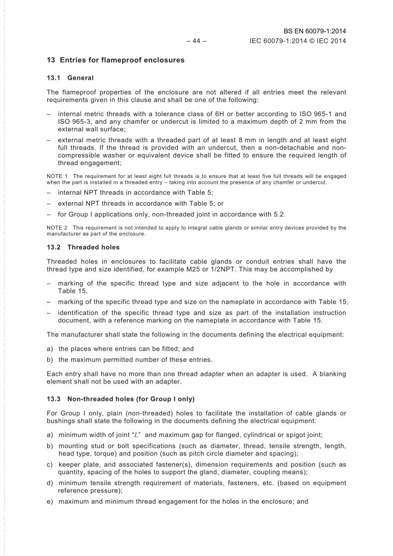
– 44 – IEC 60079-1:2014 © IEC 2014
13 Entries for flameproof enclosures
13.1 General
The flameproof properties of the enclosure are not altered if all entries meet the relevant requirements given in this clause and shall be one of the following:
– internal metric threads with a tolerance class of 6H or better according to ISO 965-1 and ISO 965-3, and any chamfer or undercut is limited to a maximum depth of 2 mm from the external wall surface;
– external metric threads with a threaded part of at least 8 mm in length and at least eight full threads. If the thread is provided with an undercut, then a non-detachable and non-compressible washer or equivalent device shall be fitted to ensure the required length of thread engagement;
NOTE 1 The requirement for at least eight full threads is to ensure that at least five full threads will be engaged when the part is installed in a threaded entry – taking into account the presence of any chamfer or undercut.
– internal NPT threads in accordance with Table 5; – external NPT threads in accordance with Table 5; or – for Group I applications only, non-threaded joint in accordance with 5.2.
NOTE 2 This requirement is not intended to apply to integral cable glands or similar entry devices provided by the manufacturer as part of the enclosure.
13.2 Threaded holes
Threaded holes in enclosures to facilitate cable glands or conduit entries shall have the thread type and size identified, for example M25 or 1/2NPT. This may be accomplished by
– marking of the specific thread type and size adjacent to the hole in accordance with Table 15,
– marking of the specific thread type and size on the nameplate in accordance with Table 15, – identification of the specific thread type and size as part of the installation instruction
document, with a reference marking on the nameplate in accordance with Table 15.
The manufacturer shall state the following in the documents defining the electrical equipment:
a) the places where entries can be fitted; and b) the maximum permitted number of these entries.
Each entry shall have no more than one thread adapter when an adapter is used. A blanking element shall not be used with an adapter.
13.3 Non-threaded holes (for Group I only)
For Group I only, plain (non-threaded) holes to facilitate the installation of cable glands or bushings shall state the following in the documents defining the electrical equipment:
a) minimum width of joint “L” and maximum gap for flanged, cylindrical or spigot joint;
b) mounting stud or bolt specifications (such as diameter, thread, tensile strength, length, head type, torque) and position (such as pitch circle diameter and spacing);
c) keeper plate, and associated fastener(s), dimension requirements and position (such as quantity, spacing of the holes to support the gland, diameter, coupling means);
d) minimum tensile strength requirement of materials, fasteners, etc. (based on equipment reference pressure);
e) maximum and minimum thread engagement for the holes in the enclosure; and
BS EN 60079-1:2014

IEC 60079-1:2014 © IEC 2014 – 45 –
f) information that will relate the length of fasteners to thickness of the keeper plate under the fastener head to ensure that the fasteners will have correct engagement and will allow correct space at the bottom of holes in accordance with 11.7 where applicable.
Figure 22 provides an example of how the possible documentation could appear.
Nominal entry size
Max. bore dia.
Min. gland dia.
50,8 63,5 76,2 95,3 108
114,3
50,96 63,62 76,35 95,40 108,10 114,50
50,56 63,22 75,95 95,00
107,70 114,10
12,5 min. flamepath
Min. gland dia.
Max. bore dia.
8 min. thread engagement
Keep plate
M8 × 1,25 × 16 capscrew M8 × 2 l’ washer (opt.)
O-ring (opt.)
IEC 1922/14
Material details and minimum tensile strength should be specified and may be tabulated in a materials table elsewhere in the documentation. Drill hole depth of fastener holes, keeper plate details (thickness, geometry, tensile strength), quantity and location of mounting fasteners should be provided.
Figure 22 – Example of possible documentation
13.4 Cable glands
Cable glands, whether integral or separate, shall meet the requirements of this standard, the relevant requirements of Annex C and create, on the enclosure, the joint widths and gaps prescribed in Clause 5.
Where cable glands are integral with the enclosure or specific to the enclosure, they shall be tested as part of the enclosure concerned.
Where cable glands are separate:
a) threaded Ex cable glands and non-threaded Ex cable glands (for Group I only) can be evaluated as equipment. Such cable glands do not have to be submitted to the tests of 15.1, nor to the routine test of Clause 16;
b) other cable glands can only be evaluated as an Ex component; and c) sufficient information shall be provided in the documentation to facilitate the mounting in
holes according to 13.2 or 13.3, as applicable.
13.5 Conduit sealing devices
13.5.1 Conduit sealing devices, whether integral or separate, shall meet the requirements of this standard, the requirements of C.2.1.2 and C.3.1.2 with "conduit sealing device" substituted for "cable gland" and create, on the enclosure, the joint widths and gaps prescribed in Clause 5.
NOTE As such constructions preclude reuse, the requirement of C.2.1.2 that a conduit sealing device be capable of being fitted and removed without disturbing the compound seal after the specified curing period of the compound cannot be applied.
Where conduit sealing devices are integral with the enclosure or specific to the enclosure, they shall be tested as part of the enclosure concerned.
Where conduit sealing devices are separate:
BS EN 60079-1:2014
– 46 – IEC 60079-1:2014 © IEC 2014
– threaded Ex conduit sealing devices can be evaluated as equipment. Such conduit sealing devices do not have to be submitted to the tests of 15.2, nor to the routine test of Clause 16;
– other conduit sealing devices can only be evaluated as an Ex component; and – sufficient information shall be provided in the documentation to facilitate the installation in
holes according to 13.2.
13.5.2 Conduit entries are permitted only for electrical equipment of Group II.
13.5.3 A sealing device such as a stopping box with setting compound shall be provided, either as part of the flameproof enclosure or immediately at the entrance thereto. It shall satisfy the type test for sealing prescribed in Annex C. An evaluated sealing device may be applied by the installer or user of the equipment according to instructions provided by the manufacturer of the equipment.
NOTE A sealing device is considered as fitted immediately at the entrance of the flameproof enclosure when the device is fixed to the enclosure either directly or through an accessory necessary for coupling.
The sealing compound(s) and method(s) of application shall be specified in the certificate either of the stopping box or of the complete flameproof equipment. The part of the stopping box between the sealing compound and the flameproof enclosure shall be treated as a flameproof enclosure, i.e. the joints shall comply with Clause 5 and the assembly shall be submitted to the tests for non-transmission of 15.3.
The distance from the face of the seal closest to the enclosure (or intended end-use enclosure), and the outside wall of the enclosure (or intended end-use enclosure) shall be as small as practical, but in no case more than the size of the conduit or 50 mm, whichever is the lesser.
13.6 Plugs and sockets and cable couplers
13.6.1 If attached on a flameproof enclosure plugs and sockets shall be constructed and mounted so that they do not alter the flameproof properties of the enclosure on which they are mounted, even when the two parts of the plugs and sockets are separated.
13.6.2 The widths and the gaps of the flameproof joints (see Clause 5) of the flameproof enclosures of plugs and sockets and cable couplers shall be determined by the volume which exists at the moment of separation of the contacts other than those for earthing or bonding or those which are parts of circuits complying with IEC 60079-11.
13.6.3 For plugs and sockets and cable couplers, the flameproof properties of the enclosure shall be maintained in the event of an internal explosion, both when the plugs and sockets or cable couplers are connected together and at the moment of separation of the contacts, other than those for earthing or bonding or those which are parts of circuits complying with IEC 60079-11.
13.6.4 If not connected to an interlocking switch which ensures a time delay between switching of the load and disconnecting the plug and socket, the plug and socket shall remain flameproof during the arc-quenching period while opening a test circuit of the rated voltage and rated current. For a.c. circuits, the test circuit power factor shall be less than or equal to 0,6, unless the equipment is marked for resistive loads only.
13.6.5 The requirements of 13.6.2 through 13.6.4 inclusive do not apply to plugs and sockets or to cable couplers fixed together by means of special fasteners conforming to 11.1 and which bear a marking in accordance with Table 14, point b).
BS EN 60079-1:2014
IEC 60079-1:2014 © IEC 2014 – 47 –
13.7 Bushings
Bushings, whether integral or separate, shall meet the requirements of this standard, the relevant requirements of Annex C and create, on the enclosure, the joint widths and gaps prescribed in Clause 5.
Where bushings are integral with the enclosure or specific to the enclosure, they shall be tested as part of the enclosure concerned.
Where bushings are separate:
a) threaded Ex bushings for Group I or II, and non-threaded Ex bushings for Group I, can be evaluated as equipment. Such bushings do not have to be submitted to the tests of 15.2, nor to the routine test of Clause 16;
b) other bushings can only be evaluated as an Ex component; and c) sufficient information shall be provided in the documentation to facilitate the mounting in
holes according to 13.2 or 13.3, as applicable.
13.8 Blanking elements
If, at the determination of the manufacturer, entries provided in a flameproof enclosure are not intended to always be used, they shall be closed by Ex equipment or Ex component blanking elements so that the flameproof properties of the enclosure are maintained.
Ex Equipment or component blanking elements shall comply with Annex C.
Ex component blanking elements are only suitable when specified as part of the Ex equipment certificate.
A blanking element shall not be used with a thread adapter.
Sufficient information shall be provided in the documentation to facilitate the mounting in holes according to 13.2 or 13.3, as applicable.
14 Verification and tests
The requirements of IEC 60079-0 concerning verification and testing are, for the type of protection flameproof enclosure “d”, supplemented by the following requirements.
The determination of the maximum surface temperature specified in IEC 60079-0 shall be made under the conditions defined in Table 6 of this standard.
BS EN 60079-1:2014
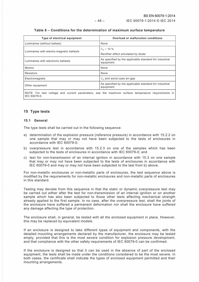
– 48 – IEC 60079-1:2014 © IEC 2014
Table 6 – Conditions for the determination of maximum surface temperature
Type of electrical equipment Overload or malfunction conditions
Luminaires (without ballast) None
Luminaires with electro-magnetic ballasts Un + 10 %
Rectifier effect simulated by diode
Luminaires with electronic ballasts As specified by the applicable standard for industrial equipment
Motors None
Resistors None
Electromagnets Un and worst-case air-gap
Other equipment As specified by the applicable standard for industrial equipment
NOTE For test voltage and current parameters, see the maximum surface temperature requirements in IEC 60079-0.
15 Type tests
15.1 General
The type tests shall be carried out in the following sequence:
a) determination of the explosion pressure (reference pressure) in accordance with 15.2.2 on one sample that may or may not have been subjected to the tests of enclosures in accordance with IEC 60079-0;
b) overpressure test in accordance with 15.2.3 on one of the samples which has been subjected to the tests of enclosures in accordance with IEC 60079-0; and
c) test for non-transmission of an internal ignition in accordance with 15.3 on one sample that may or may not have been subjected to the tests of enclosures in accordance with IEC 60079-0 and may or may not have been subjected to the test from b) above.
For non-metallic enclosures or non-metallic parts of enclosures, the test sequence above is modified by the requirements for non-metallic enclosures and non-metallic parts of enclosures in this standard.
Testing may deviate from this sequence in that the static or dynamic overpressure test may be carried out either after the test for non-transmission of an internal ignition or on another sample which has also been subjected to those other tests affecting mechanical strength already applied to the first sample. In no case, after the overpressure test, shall the joints of the enclosure have suffered a permanent deformation nor shall the enclosure have suffered any damage affecting the type of protection.
The enclosure shall, in general, be tested with all the enclosed equipment in place. However, this may be replaced by equivalent models.
If an enclosure is designed to take different types of equipment and components, with the detailed mounting arrangements declared by the manufacturer, the enclosure may be tested empty, provided that this is the most severe condition for explosion pressure development, and that compliance with the other safety requirements of IEC 60079-0 can be confirmed.
If the enclosure is designed so that it can be used in the absence of part of the enclosed equipment, the tests shall be made under the conditions considered to be the most severe. In both cases, the certificate shall indicate the types of enclosed equipment permitted and their mounting arrangements.
BS EN 60079-1:2014

IEC 60079-1:2014 © IEC 2014 – 49 –
Joints of removable parts of flameproof enclosures shall be tested in the worst-case assembly conditions.
15.2 Tests of ability of the enclosure to withstand pressure
15.2.1 General
The object of these tests is to verify that the enclosure can withstand the pressure of an internal explosion.
The enclosure shall be subjected to tests in accordance with 15.2.2 and 15.2.3.
The tests are considered satisfactory if the enclosure suffers no permanent deformation or damage invalidating the type of protection. In addition, the joints shall in no place have been permanently enlarged.
15.2.2 Determination of explosion pressure (reference pressure)
15.2.2.1 General
The reference pressure is the highest value of the maximum smoothed pressure, relative to atmospheric pressure, observed during these tests. For smoothing, a low-pass filter with a 3 dB point of 5 kHz ± 0.5 kHz shall be used.
For electrical equipment intended for use at an ambient temperature below –20 °C, the reference pressure shall be determined by one of the following methods.
– For all electrical equipment, the reference pressure shall be determined at a temperature not higher than the minimum ambient temperature.
– For all electrical equipment, the reference pressure shall be determined at normal ambient temperature using the defined test mixture(s), but at increased pressure. The absolute pressure of the test mixture (P), in kPa, shall be calculated by the following formula, using Ta, min in °C:
P = 100[293 / (Ta, min + 273)] kPa
– For electrical equipment other than rotating electrical machines (such as electric motors, generators and tachometers) that involve simple internal geometry (see Annex D) with an enclosure volume not exceeding 3 l, when empty, such that pressure-piling is not considered likely, the reference pressure shall be determined at normal ambient temperature using the defined test mixture(s), but is to be assumed to have a reference pressure increased by the “test factors for reduced ambient conditions” given in Table 7.
– For electrical equipment other than rotating electrical machines (such as electric motors, generators and tachometers) that involve simple internal geometry (see Annex D) with an enclosure volume not exceeding 10 l, when empty, such that pressure piling is not considered likely, the reference pressure shall be determined at normal ambient temperature using the defined test mixture(s), but is to be assumed to have a reference pressure increased by the “test factors for reduced ambient conditions” given in Table 7. Under this alternative, the test pressure for the overpressure type test in 15.2.3.2 shall be 4 times the increased reference pressure. The 1,5 times routine test is not permitted.
BS EN 60079-1:2014
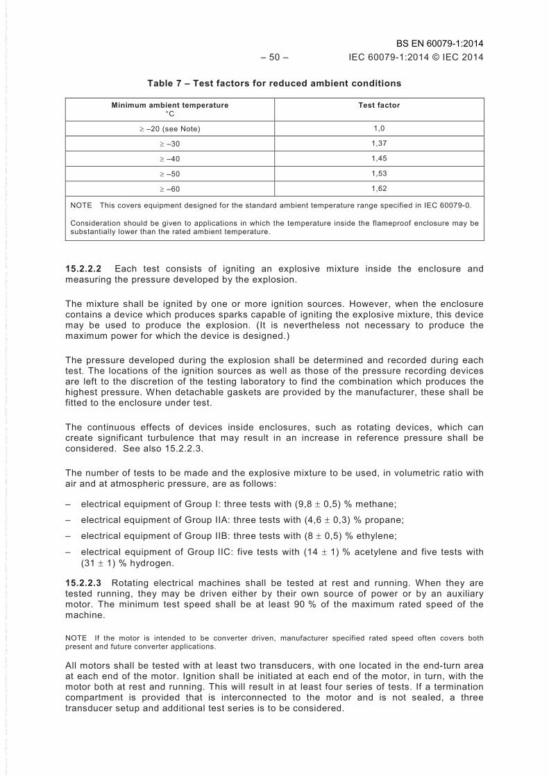
– 50 – IEC 60079-1:2014 © IEC 2014
Table 7 – Test factors for reduced ambient conditions
Minimum ambient temperature °C
Test factor
≥ –20 (see Note) 1,0
≥ –30 1,37
≥ –40 1,45
≥ –50 1,53
≥ –60 1,62
NOTE This covers equipment designed for the standard ambient temperature range specified in IEC 60079-0.
Consideration should be given to applications in which the temperature inside the flameproof enclosure may be substantially lower than the rated ambient temperature.
15.2.2.2 Each test consists of igniting an explosive mixture inside the enclosure and measuring the pressure developed by the explosion.
The mixture shall be ignited by one or more ignition sources. However, when the enclosure contains a device which produces sparks capable of igniting the explosive mixture, this device may be used to produce the explosion. (It is nevertheless not necessary to produce the maximum power for which the device is designed.)
The pressure developed during the explosion shall be determined and recorded during each test. The locations of the ignition sources as well as those of the pressure recording devices are left to the discretion of the testing laboratory to find the combination which produces the highest pressure. When detachable gaskets are provided by the manufacturer, these shall be fitted to the enclosure under test.
The continuous effects of devices inside enclosures, such as rotating devices, which can create significant turbulence that may result in an increase in reference pressure shall be considered. See also 15.2.2.3.
The number of tests to be made and the explosive mixture to be used, in volumetric ratio with air and at atmospheric pressure, are as follows:
– electrical equipment of Group I: three tests with (9,8 ± 0,5) % methane;
– electrical equipment of Group IIA: three tests with (4,6 ± 0,3) % propane;
– electrical equipment of Group IIB: three tests with (8 ± 0,5) % ethylene;
– electrical equipment of Group IIC: five tests with (14 ± 1) % acetylene and five tests with (31 ± 1) % hydrogen.
15.2.2.3 Rotating electrical machines shall be tested at rest and running. When they are tested running, they may be driven either by their own source of power or by an auxiliary motor. The minimum test speed shall be at least 90 % of the maximum rated speed of the machine.
NOTE If the motor is intended to be converter driven, manufacturer specified rated speed often covers both present and future converter applications.
All motors shall be tested with at least two transducers, with one located in the end-turn area at each end of the motor. Ignition shall be initiated at each end of the motor, in turn, with the motor both at rest and running. This will result in at least four series of tests. If a termination compartment is provided that is interconnected to the motor and is not sealed, a three transducer setup and additional test series is to be considered.
BS EN 60079-1:2014
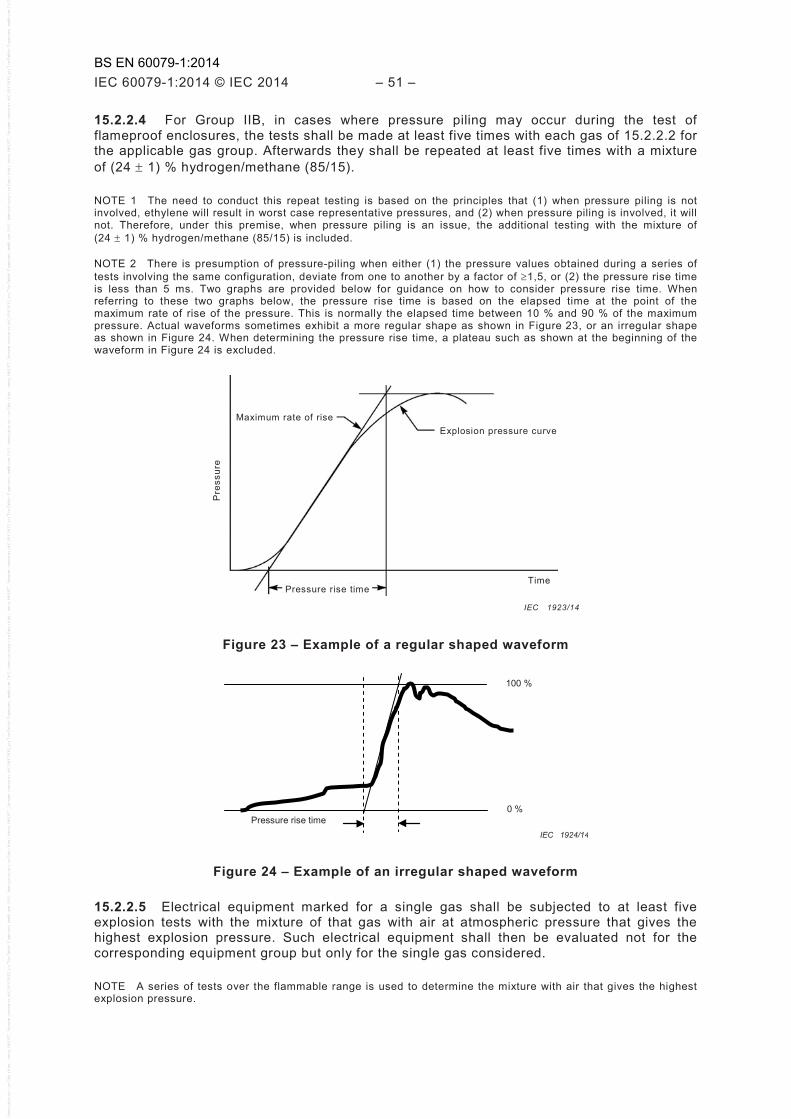
IEC 60079-1:2014 © IEC 2014 – 51 –
15.2.2.4 For Group IIB, in cases where pressure piling may occur during the test of flameproof enclosures, the tests shall be made at least five times with each gas of 15.2.2.2 for the applicable gas group. Afterwards they shall be repeated at least five times with a mixture of (24 ± 1) % hydrogen/methane (85/15).
NOTE 1 The need to conduct this repeat testing is based on the principles that (1) when pressure piling is not involved, ethylene will result in worst case representative pressures, and (2) when pressure piling is involved, it will not. Therefore, under this premise, when pressure piling is an issue, the additional testing with the mixture of (24 ± 1) % hydrogen/methane (85/15) is included.
NOTE 2 There is presumption of pressure-piling when either (1) the pressure values obtained during a series of tests involving the same configuration, deviate from one to another by a factor of ≥1,5, or (2) the pressure rise time is less than 5 ms. Two graphs are provided below for guidance on how to consider pressure rise time. When referring to these two graphs below, the pressure rise time is based on the elapsed time at the point of the maximum rate of rise of the pressure. This is normally the elapsed time between 10 % and 90 % of the maximum pressure. Actual waveforms sometimes exhibit a more regular shape as shown in Figure 23, or an irregular shape as shown in Figure 24. When determining the pressure rise time, a plateau such as shown at the beginning of the waveform in Figure 24 is excluded.
Figure 23 – Example of a regular shaped waveform
Pressure rise time
0 %
100 %
IEC 1924/14
Figure 24 – Example of an irregular shaped waveform
15.2.2.5 Electrical equipment marked for a single gas shall be subjected to at least five explosion tests with the mixture of that gas with air at atmospheric pressure that gives the highest explosion pressure. Such electrical equipment shall then be evaluated not for the corresponding equipment group but only for the single gas considered.
NOTE A series of tests over the flammable range is used to determine the mixture with air that gives the highest explosion pressure.
Maximum rate of rise Explosion pressure curve
Time Pressure rise time
Pre
ssur
e
IEC 1923/14
BS EN 60079-1:2014

– 52 – IEC 60079-1:2014 © IEC 2014
Where exclusion of a specific gas or gases is required, the certificate number shall include the "X" suffix in accordance with the marking requirements of IEC 60079-0 and the specific conditions of use listed on the certificate shall detail this exclusion.
Double marking can be applied for a specific gas and for the next lowest group to the group of this gas (for example, IIB + H2), if the enclosure has been submitted not only to the tests for the specific gas, but also to those necessary for the lower group.
15.2.3 Overpressure test
15.2.3.1 General
This test shall be made using either of the following methods, which are considered as equivalent.
15.2.3.2 Overpressure test – First method (static)
The relative pressure applied shall be
– 1,5 times the reference pressure; or – 4 times the reference pressure for enclosures not subject to routine overpressure testing;
or – 3 times the reference pressure for enclosure where the routine overpressure testing is
replaced by a batch test (see 16.6); or – at the pressures given in Table 8, when reference pressure determination has been
impracticable due to the small size of the equipment.
Table 8 – Relative pressures for small equipment
Volume cm3
Group Pressurea kPa
≤10 I, IIA, IIB, IIC 1 000
>10 I 1 000
>10 IIA, IIB 1 500
>10 IIC 2 000 a For equipment intended for use at an ambient temperature below –20 °C, the above pressures shall be
increased by the appropriate test factors noted in Table 7.
The period of application of the pressure shall be at least 10 s.
The test is performed once on each sample, as applicable.
The overpressure test shall be considered satisfactory if the test result is in compliance with 15.2.1 and if there is no leakage through the walls of the enclosure.
NOTE A non-compressible hydraulic media is normally used for these tests. If a compressible media such as air or inert gas is used, failure of the enclosure can result in personal injury or property damage.
15.2.3.3 Overpressure test – Second method (dynamic)
The dynamic tests shall be carried out in such a way that the maximum pressure to which the enclosure is subjected is 1,5 times the reference pressure.
When the test is carried out with mixtures specified in 15.2.2.2, these may be precompressed to produce an explosion pressure of 1,5 times the reference pressure.
BS EN 60079-1:2014
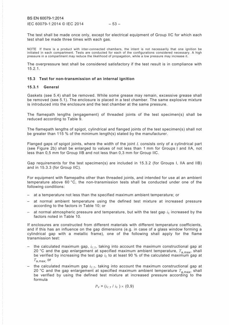
IEC 60079-1:2014 © IEC 2014 – 53 –
The test shall be made once only, except for electrical equipment of Group IIC for which each test shall be made three times with each gas.
NOTE If there is a product with inter-connected chambers, the intent is not necessarily that one ignition be initiated in each compartment. Tests are conducted for each of the configurations considered necessary. A high pressure in a compartment may reduce the likelihood of propagation, while a low pressure may increase it.
The overpressure test shall be considered satisfactory if the test result is in compliance with 15.2.1.
15.3 Test for non-transmission of an internal ignition
15.3.1 General
Gaskets (see 5.4) shall be removed. While some grease may remain, excessive grease shall be removed (see 5.1). The enclosure is placed in a test chamber. The same explosive mixture is introduced into the enclosure and the test chamber at the same pressure.
The flamepath lengths (engagement) of threaded joints of the test specimen(s) shall be reduced according to Table 9.
The flamepath lengths of spigot, cylindrical and flanged joints of the test specimen(s) shall not be greater than 115 % of the minimum length(s) stated by the manufacturer.
Flanged gaps of spigot joints, where the width of the joint L consists only of a cylindrical part (see Figure 2b) shall be enlarged to values of not less than 1 mm for Groups I and IIA, not less than 0,5 mm for Group IIB and not less than 0,3 mm for Group IIC.
Gap requirements for the test specimen(s) are included in 15.3.2 (for Groups I, IIA and IIB) and in 15.3.3 (for Group IIC).
For equipment with flamepaths other than threaded joints, and intended for use at an ambient temperature above 60 °C, the non-transmission tests shall be conducted under one of the following conditions:
– at a temperature not less than the specified maximum ambient temperature; or – at normal ambient temperature using the defined test mixture at increased pressure
according to the factors in Table 10; or – at normal atmospheric pressure and temperature, but with the test gap iE increased by the
factors noted in Table 10.
If enclosures are constructed from different materials with different temperature coefficients, and if this has an influence on the gap dimensions (e.g. in case of a glass window forming a cylindrical gap with a metallic frame), one of the following shall apply for the flame transmission test:
– the calculated maximum gap, iC,T, taking into account the maximum constructional gap at 20 °C and the gap enlargement at specified maximum ambient temperature, Ta,max, shall be verified by increasing the test gap iE to at least 90 % of the calculated maximum gap at Ta,max; or
– the calculated maximum gap iC,T, taking into account the maximum constructional gap at 20 °C and the gap enlargement at specified maximum ambient temperature Ta,max, shall be verified by using the defined test mixture at increased pressure according to the formula
PV = (iC,T / iE ) × (0,9)
BS EN 60079-1:2014
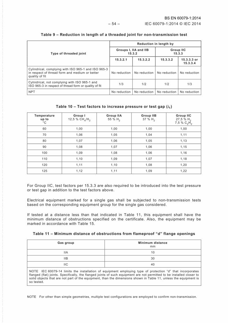
– 54 – IEC 60079-1:2014 © IEC 2014
Table 9 – Reduction in length of a threaded joint for non-transmission test
Type of threaded joint
Reduction in length by
Groups I, IIA and IIB 15.3.2
Group IIC 15.3.3
15.3.2.1 15.3.2.2 15.3.3.2 15.3.3.3 or 15.3.3.4
Cylindrical, complying with ISO 965-1 and ISO 965-3 in respect of thread form and medium or better quality of fit
No reduction No reduction No reduction No reduction
Cylindrical, not complying with ISO 965-1 and ISO 965-3 in respect of thread form or quality of fit 1/3 1/2 1/2 1/3
NPT No reduction No reduction No reduction No reduction
Table 10 – Test factors to increase pressure or test gap (iE)
Temperature up to
°C
Group I 12,5 % CH4/H2
Group IIA 55 % H2
Group IIB 37 % H2
Group IIC 27,5 % H2
7,5 % C2H2
60 1,00 1,00 1,00 1,00
70 1,06 1,05 1,04 1,11
80 1,07 1,06 1,05 1,13
90 1,08 1,07 1,06 1,15
100 1,09 1,08 1,06 1,16
110 1,10 1,09 1,07 1,18
120 1,11 1,10 1,08 1,20
125 1,12 1,11 1,09 1,22
For Group IIC, test factors per 15.3.3 are also required to be introduced into the test pressure or test gap in addition to the test factors above.
Electrical equipment marked for a single gas shall be subjected to non-transmission tests based on the corresponding equipment group for the single gas considered.
If tested at a distance less than that indicated in Table 11, this equipment shall have the minimum distance of obstructions specified on the certificate. Also, the equipment may be marked in accordance with Table 15.
Table 11 – Minimum distance of obstructions from flameproof “d” flange openings
Gas group Minimum distance mm
IIA 10
IIB 30
IIC 40
NOTE IEC 60079-14 limits the installation of equipment employing type of protection “d” that incorporates flanged (flat) joints. Specifically, the flanged joints of such equipment are not permitted to be installed closer to solid objects that are not part of the equipment, than the dimensions shown in Table 11, unless the equipment is so tested.
NOTE For other than simple geometries, multiple test configurations are employed to confirm non-transmission.
BS EN 60079-1:2014
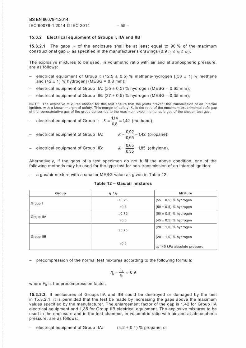
IEC 60079-1:2014 © IEC 2014 – 55 –
15.3.2 Electrical equipment of Groups I, IIA and IIB
15.3.2.1 The gaps iE of the enclosure shall be at least equal to 90 % of the maximum constructional gap iC as specified in the manufacturer's drawings (0,9 iC ≤ iE ≤ iC).
The explosive mixtures to be used, in volumetric ratio with air and at atmospheric pressure, are as follows:
– electrical equipment of Group I: (12,5 ± 0,5) % methane-hydrogen [(58 ± 1) % methane and (42 ± 1) % hydrogen] (MESG = 0,8 mm);
– electrical equipment of Group IIA: (55 ± 0,5) % hydrogen (MESG = 0,65 mm);
– electrical equipment of Group IIB: (37 ± 0,5) % hydrogen (MESG = 0,35 mm);
NOTE The explosive mixtures chosen for this test ensure that the joints prevent the transmission of an internal ignition, with a known margin of safety. This margin of safety, K, is the ratio of the maximum experimental safe gap of the representative gas of the group concerned to the maximum experimental safe gap of the chosen test gas.
– electrical equipment of Group I: 42180
141 ,,
,==K (methane);
– electrical equipment of Group IIA: 421650920 ,,,
==K (propane);
– electrical equipment of Group IIB: 851350650 ,,,
==K (ethylene).
Alternatively, if the gaps of a test specimen do not fulfil the above condition, one of the following methods may be used for the type test for non-transmission of an internal ignition:
– a gas/air mixture with a smaller MESG value as given in Table 12:
Table 12 – Gas/air mixtures
Group iE / iC Mixture
Group I ≥0,75 (55 ± 0,5) % hydrogen
≥0,6 (50 ± 0,5) % hydrogen
Group IIA ≥0,75 (50 ± 0,5) % hydrogen
≥0,6 (45 ± 0,5) % hydrogen
Group IIB
≥0,75 (28 ± 1,0) % hydrogen
(28 ± 1,0) % hydrogen
≥0,6 at 140 kPa absolute pressure
– precompression of the normal test mixtures according to the following formula:
0,9 E
Ck ×=
iiP
where Pk is the precompression factor.
15.3.2.2 If enclosures of Groups IIA and IIB could be destroyed or damaged by the test in 15.3.2.1, it is permitted that the test be made by increasing the gaps above the maximum values specified by the manufacturer. The enlargement factor of the gap is 1,42 for Group IIA electrical equipment and 1,85 for Group IIB electrical equipment. The explosive mixtures to be used in the enclosure and in the test chamber, in volumetric ratio with air and at atmospheric pressure, are as follows:
– electrical equipment of Group IIA: (4,2 ± 0,1) % propane; or
BS EN 60079-1:2014

– 56 – IEC 60079-1:2014 © IEC 2014
– electrical equipment of Group IIB: (6,5 ± 0,5) % ethylene.
15.3.2.3 The test in 15.3.2.1 or 15.3.2.2 shall be made five times taking each test configuration into consideration. The test result is considered satisfactory if the ignition is not transmitted to the test chamber.
15.3.3 Electrical equipment of Group lIC
15.3.3.1 General
The tests in 15.3.3.2, 15.3.3.3 or 15.3.3.4 can be used for this test, and are considered satisfactory if the ignition is not transmitted to the test chamber.
NOTE The methods below are equivalent in their factors of safety, 1,5, and the minimum test gap of 90 %. This is accomplished by either increasing the pressure or by increasing the test gap dimension or by increasing the oxygen of the test mixture.
15.3.3.2 First method – Testing by increased test gap
All gaps of joints other than threaded joints shall be increased to the value
1,35 iC ≤ iE ≤ 1,5 iC
with a minimum of 0,1 mm for flanged joints
where iE is the test gap; iC is the maximum constructional gap, as specified on the manufacturer's drawings.
The following explosive mixtures, in volumetric ratio with air and at atmospheric pressure, shall be used in the enclosure and in the test chamber:
a) (27,5 ± 1,5) % hydrogen, and
b) (7,5 ± 1) % acetylene.
Five tests taking each test configuration into consideration shall be made with each mixture. If the equipment is intended for use solely with hydrogen or solely with acetylene, the tests shall be made only with the corresponding gas mixture.
NOTE When preparing a test sample employing a cylindrical joint of a shaft gland for a rotating machine with roller element bearings, the test gap iE is based on the diametrical clearance from Table 2 or Table 3, and not the radial clearance of 8.2.2.
15.3.3.3 Second method – Testing by increased pressure
The enclosure shall be tested with a test gap iE according to the following formula:
0,9 iC ≤ iE ≤ iC
The enclosure and the test chamber are filled with one of the gas mixtures specified for the first method at a pressure equal to 1,5 times atmospheric pressure.
The test shall be carried out five times with each explosive mixture.
Alternatively, if the gaps of a test specimen do not fulfil the above condition, the following method may be used.
Precompression of the normal test mixtures according to the following formula:
BS EN 60079-1:2014
IEC 60079-1:2014 © IEC 2014 – 57 –
1,35 E
Ck ×=
iiP
where Pk is the precompression factor.
NOTE When preparing a test sample employing a cylindrical joint of a shaft gland for a rotating machine with roller element bearings, the test gap iE is based on the diametrical clearance from Table 2 or Table 3, and not the radial clearance of 8.2.2.
15.3.3.4 Third method – Testing by oxygen enrichment of test gases
The gaps iE of the enclosure shall be at least equal to 90 % of the maximum constructional gap iC as specified in the manufacturer's drawings (0,9 iC ≤ iE ≤ iC).
The test mixtures to be used consist of the following, in volumetric ratio and at atmospheric pressure:
a) (40 ± 1) % hydrogen, (20 ± 1) % oxygen and the rest nitrogen; and
b) (10 ± 1) % acetylene, (24 ± 1) % oxygen and the rest nitrogen.
The tests shall be carried out five times with each test mixture. For devices intended for use only in hydrogen, only test mixture a) is required.
15.3.3.5 Number of tests for single piece production
Electrical equipment which are a single piece production shall be tested a total of five times, taking each test configuration into consideration, with unaltered test gaps and with each of the explosive mixtures specified in 15.3.3.2 at atmospheric pressure and the dimensional requirements of 5.1 apply.
15.4 Tests of flameproof enclosures with breathing and draining devices
15.4.1 General
The tests in accordance with 15.4.2 to 15.4.4 inclusive shall be carried out in the following order on a sample after the impact strength test of 10.7.2.
For devices with non-measurable paths, the maximum bubble test pore size of the sample shall not be less than 85 % of the specified maximum bubble test pore size. See Annex B.
15.4.2 Tests of ability of the enclosure to withstand pressure
15.4.2.1 The tests shall be made in accordance with 15.2 with the following additions and modifications.
15.4.2.2 For the determination of the explosion pressure in accordance with 15.2.2, breathing and draining devices shall be replaced by solid plugs.
15.4.2.3 For the overpressure test in accordance with 15.2.3, a thin flexible membrane (for example, a thin plastic sheet) shall be fitted to the inner surfaces of the breathing and draining devices. After the overpressure test, the device shall show no permanent deformation or damage likely to affect the type of protection.
NOTE The intent of the thin flexible membrane is to minimize leakage during the test without influencing the strength of the device.
BS EN 60079-1:2014

– 58 – IEC 60079-1:2014 © IEC 2014
15.4.3 Thermal tests
15.4.3.1 Test procedure
The enclosure, with the device(s) fitted, shall be tested in accordance with the method 15.4.4.2 but with the ignition source only in the position giving the most unfavourable thermal results.
The temperature of the external surface of the device(s) shall be monitored during the test. The test shall be carried out five times. The test mixture to be used shall be (4,2 ± 0,1) % propane in volumetric ratio with air and at atmospheric pressure. Additionally, for devices intended for use in acetylene, (7,5 ± 1,0) % acetylene in volumetric ratio with air and at atmospheric pressure shall be used.
In an enclosure where there is the possibility of a forced or induced flow of a potentially dangerous gas, the enclosure shall be arranged during the tests so that the gas can flow through the device(s) and the enclosure.
Any ventilation or sampling system shall be operated as specified in the manufacturer's documentation. After each of the five tests, the external explosive mixture shall be maintained for a sufficient time to allow any continuous burning on the face of the device to become evident (for example, for at least 10 min so as to increase the temperature of the external surface of the device or to make heat transfer to the outer face possible).
NOTE The temperature of the external surface after the 10 min test period is used in determining the temperature class in accordance with 15.4.3.2.
15.4.3.2 Acceptance criterion
No continuous burning shall be observed. No flame transmission shall occur. The measured external surface temperature rise of the device shall be multiplied by a safety factor of 1,2 and added to the maximum service temperature of the device for the determination of the temperature class of the electrical equipment.
15.4.4 Test for non-transmission of an internal ignition
15.4.4.1 General
This test shall be made in accordance with 15.3 with the following additions and modifications.
15.4.4.2 Test procedure
An ignition source shall be placed first close to the inner surface of the breathing and draining device and subsequently in one or more places if a high peak explosion pressure and rate of rise of pressure at the face of the device is likely to occur. Where the enclosure has more than one identical device, the device to be tested shall be that which gives the most unfavourable results. The test mixture within the enclosure shall be ignited. The test shall be made five times for each position of the ignition source.
15.4.4.3 Non-transmission test for breathing and draining devices
15.4.4.3.1 General
For breathing and draining devices of Groups I, IIA and IIB, the non-transmission test of 15.3.2 shall be applied.
For breathing and draining devices of Group IIC with measurable paths, the non-transmission tests of 15.3.3 shall be applied. For breathing and draining devices of Group IIC with non-measurable paths, the non-transmission tests of 15.4.4.3.2 or 15.4.4.3.3 shall be applied.
BS EN 60079-1:2014

IEC 60079-1:2014 © IEC 2014 – 59 –
15.4.4.3.2 Method A – Testing by increased pressure
The tests are carried out five times with each test mixture. The tests are made according to 15.3.3.3 and 15.4.4.2.
For devices intended for use only in hydrogen, only the test with the hydrogen/air mixture is required.
15.4.4.3.3 Method B – Testing by oxygen enrichment of test gases
Carbon disulphide is excluded for enclosures with a volume greater than 100 cm3. The test mixtures to be used consist of the following, in volumetric ratio and at atmospheric pressure:
a) (40 ± 1) % hydrogen, (20 ± 1) % oxygen and the rest nitrogen; and
b) (10 ± 1) % acetylene, (24 ± 1) % oxygen and the rest nitrogen.
The tests shall be carried out five times with each test mixture, in accordance with 15.4.4.2.
For devices intended for use only in hydrogen, only test mixture a) is required.
15.4.4.4 Acceptance criterion
The test result is considered satisfactory if no ignition is transmitted to the test chamber.
15.5 Tests for “dc” devices
15.5.1 General
The tests of 15.5 replace the tests of 15.2 through 15.4.4.4.
15.5.2 Preparation of “dc” samples
Any elastomeric or thermoplastic material which is used for the purpose of sealing a cover which is intended to be opened in service, or which is unprotected against mechanical or environmental damage, shall be removed wholly or partially before the device or component is subjected to the type test when such removal will result in a more onerous test.
NOTE Any remaining non-metallic parts of the enclosure will have been subjected to the thermal endurance tests.
15.5.3 Test conditions for “dc” devices
15.5.3.1 General
The device or component, which shall be arranged to have the most adverse dimensions permitted by the construction drawings, shall be filled with and surrounded by an explosive mixture according to the stated group of the equipment, as follows:
– Group IIA: (55 ± 0,5) % hydrogen/air at atmospheric pressure;
– Group IIB: (37 ± 0,5) % hydrogen/air at atmospheric pressure;
– Group IIC: (40 ± 1) % hydrogen, (20 ± 1) % oxygen and the remainder nitrogen at atmospheric pressure or alternatively (27,5 ± 1,5) % hydrogen/air at an overpressure at a pressure equal to 1,5 times atmospheric pressure.
15.5.3.2 Test procedure
For “dc”, the explosive mixture within the device shall be ignited by the operation of the enclosed contacts when connected to the maximum rated source of energy and power, and maximum load, in terms of voltage, current, frequency and power factor. A make and break test shall be made 10 times with a fresh explosive mixture for each test and the explosive mixture surrounding the device shall not be ignited.
BS EN 60079-1:2014

– 60 – IEC 60079-1:2014 © IEC 2014
16 Routine tests
16.1 General
16.1.1 The following routine tests are intended to ensure that the enclosure withstands the pressure and also that it contains no holes or cracks connecting to the exterior.
The routine tests include an overpressure test made according to one of the methods described for the type tests in 15.2.3. For equipment intended for use at an ambient temperature below –20 °C, a pressure test at normal ambient temperature is sufficient.
16.1.2 The routine overpressure test may be made by the first method even when the overpressure type test has been made by the second method.
When the determination of the reference pressure has been impracticable and when a dynamic test involves a risk to the enclosed equipment (windings, etc.), the static pressures to be applied are as given in Table 13.
Table 13 – Static pressures
Volume cm3
Group Pressureb kPa
≤10a I, IIA, IIB, IIC 1 000
>10 I 1 000
>10 IIA, IIB 1 500
>10 lIC 2 000 a Applicable to welded constructions only. b For equipment intended for use at an ambient temperature below –20 °C, the above pressures shall be
increased by the appropriate test factors noted in Table 7.
16.1.3 When the second method is chosen, the routine test consists of
– an explosion test with, inside and outside the enclosure, the appropriate explosive mixture specified in 15.2.2 (for the determination of explosion pressure) at 1,5 times atmospheric pressure, or
– an explosion test with the appropriate explosive mixture specified in 15.2.2 (for the determination of explosion pressure) at 1,5 times atmospheric pressure inside of the enclosure, followed by a non-transmission test with explosive mixtures as specified in 15.3.2.2 or 15.3.3.2 (test for non-transmission of an internal ignition, with enlarged gaps) inside and outside the enclosure at atmospheric pressure, or
– an explosion test with the appropriate explosive mixture specified in 15.2.2 (for the determination of explosion pressure) at 1,5 times atmospheric pressure, followed by a static test at a pressure of at least 200 kPa.
16.1.4 For the routine test, it is sufficient to test the enclosure empty. However, if the routine test is dynamic and the enclosed equipment influences the pressure rise during an internal explosion, the test conditions shall address this influence.
The individual parts of a flameproof enclosure (for example, cover and base) can be tested separately. The test conditions shall be such that the stresses are comparable to those to which these parts are exposed in the complete enclosure.
NOTE A non-compressible hydraulic media is normally used for these tests. If a compressible media such as air or inert gas is used, failure of the enclosure can result in personal injury or property damage.
BS EN 60079-1:2014
IEC 60079-1:2014 © IEC 2014 – 61 –
16.2 Enclosures not incorporating a welded construction
For enclosures that do not incorporate welded constructions, routine overpressure tests are not required under either of the following conditions:
– for volumes less than or equal to 10 cm3; or – for volumes greater than 10 cm3, and when the prescribed type test has been made at a
static pressure equal to four times the reference pressure.
16.3 Enclosures incorporating a welded construction
For enclosures or parts of enclosures that incorporate a welded construction, the integrity of the welded construction shall be verified by means of routine overpressure testing.
Alternatively, when routine overpressure testing of a welded construction is impractical (such as due to the construction of the enclosure), and when the enclosure complies with the 4 times overpressure type test, the integrity of the welds may be verified by one of the following inspection methods:
– radiographic weld inspection; or – ultrasonic weld inspection; or – magnetic particle weld inspection; or – liquid penetrant weld inspection.
NOTE ISO standards exist for each of the above weld inspection methods.
16.4 Bushings not specific to one flameproof enclosure
Routine tests are not required for bushings that are not specific to one flameproof enclosure, if the assembly procedure is sufficiently documented (see C.2.1.4).
16.5 Acceptance criteria
The routine tests are considered satisfactory if
a) the enclosure withstands the pressure without suffering permanent deformation of the joints or damage to the enclosure, and
b) when the test has been made by the dynamic followed by the static tests of 16.1.3, there is no leakage through the walls of the enclosure or, if tested dynamically, there is no transmission of an internal ignition.
16.6 Batch testing
Where the routine overpressure testing is replaced by a batch test according to the following criteria based on ISO 2859-1[5]:
– For a production batch up to 100, a sampling of 8 needs to be tested at 1,5 times the reference pressure with no failures.
– For a production batch from 101 to 1 000, a sampling of 32 needs to be tested at 1,5 times the reference pressure with no failures.
– For a production batch from 1 001 up to 10 000, a sampling of 80 needs to be tested at 1,5 times the reference pressure with no failures.
– Batches above 10 000 must be subdivided into smaller batches.
If there is any non-compliant test results, 100 % of all remaining samples in the batch shall be tested at 1,5 times the reference pressure. Future batches should be routine tested at 1,5 times the reference pressure until confidence is established to reconsider batch testing.
NOTE Upon non-compliant test results, reconsideration of this batch testing approach is at the discretion of the party issuing the involved certificate.
BS EN 60079-1:2014
– 62 – IEC 60079-1:2014 © IEC 2014
17 Switchgear for Group I
17.1 General
Group I flameproof enclosures which are to be opened from time to time on site, for example, for adjustment purposes or for resetting of protection relays, and which contain remotely operated switching devices in which circuits can be made or broken by a separate influence (e.g. mechanical, electrical, electro-optical, pneumatic, acoustic, magnetic, or thermal) when this influence is not applied manually to the equipment itself, and which produce in-service arcs or sparks capable of igniting an explosive mixture, shall comply with the following requirements.
17.2 Means of isolation
17.2.1 General
All accessible conductors, except those of intrinsically safe circuits complying with IEC 60079-11 and those for bonding or earthing, shall be capable of being isolated from the supply before the opening of the flameproof enclosure.
The means of isolation of these flameproof enclosures shall be in accordance with 17.2.2, 17.2.3 or 17.2.4.
17.2.2 The means of isolation shall be fitted inside the flameproof enclosure, in which case the parts which remain energized after the means of isolation has been opened shall either:
– be protected by one of the standard types of protection of EPL Mb listed in IEC 60079-0; or
– have clearances and creepage distances between phases and to earth in accordance with the requirements of IEC 60079-7, and be protected by an enclosure that provides a degree of protection of at least IP20, arranged so that a tool cannot contact the energized parts through any openings. This does not apply to parts of intrinsically safe circuits complying with IEC 60079-11 which remain energized.
In either case, a marking in accordance with Table 14, point c), shall be provided on the cover protecting the parts which remain energized.
17.2.3 The means of isolation shall be fitted inside another enclosure complying with one of the standard types of protection of EPL Mb listed in IEC 60079-0.
17.2.4 The means of isolation shall consist of a plug and socket or a cable coupler complying with the requirements of 13.3.
17.3 Doors or covers
17.3.1 Quick-acting doors or covers
These doors or covers shall be mechanically interlocked with an isolator so that
a) the enclosure retains the properties of the flameproof enclosure, type of protection “d”, as long as the isolator is closed, and
b) the isolator can only be closed when these doors or covers ensure the properties of the flameproof enclosure, type of protection “d”.
17.3.2 Doors or covers fixed by screws
These doors or covers shall bear a marking in accordance with Table 14, point c).
BS EN 60079-1:2014
IEC 60079-1:2014 © IEC 2014 – 63 –
17.3.3 Threaded doors or covers
These doors or covers shall bear a marking in accordance with Table 14, point c).
18 Lampholders and Iamp caps
18.1 General
The following requirements apply to lampholders and lamp caps which together have to form a flameproof enclosure, type of protection “d”, so that they may be used in luminaires of increased safety, type of protection “e”.
18.2 Device preventing lamps working loose
The device which prevents lamps working loose, required in IEC 60079-7, increased safety “e”, may be omitted for threaded lampholders provided with a quick-acting switch in a flameproof enclosure, type of protection “d”, which breaks all poles of the lamp circuit before contact separation.
18.3 Holders and caps for lamps with cylindrical caps
18.3.1 Holders and caps for tubular fluorescent lamps shall comply with the dimensional requirements of data sheets Fa6 of IEC 60061.
18.3.2 For other holders, the requirements of Clause 5 shall apply, but the width of the flameproof joint between the holder and the cap shall be at least 10 mm at the moment of contact separation.
18.4 Holders for lamps with threaded caps
18.4.1 The threaded part of the holder shall be of a material which is resistant to corrosion under the likely conditions of service.
18.4.2 At the moment of contact separation when unscrewing the lamp, at least two complete turns of the thread shall be engaged.
18.4.3 For threaded lampholders E26/E27 and E39/E40, electrical contact shall be established by spring-loaded contact elements. In addition, for electrical equipment of Group IIB or IIC, the making and breaking of contact during insertion and removal of the lamp shall take place within a flameproof enclosure, type of protection “d”, of Group IIB or IIC, respectively.
For threaded lampholders E10 and E14, the requirements of 18.4.3 are not necessary.
19 Non-metallic enclosures and non-metallic parts of enclosures
19.1 General
The following requirements apply to non-metallic enclosures and non-metallic parts of enclosures, except for
a) sealing rings of cable glands or conduit sealing devices, for which Clause C.3 applies, b) cemented joints for which Clause 6 applies, and c) non-metallic parts on which the type of protection does not depend.
BS EN 60079-1:2014
– 64 – IEC 60079-1:2014 © IEC 2014
19.2 Resistance to tracking and creepage distances on internal surfaces of the enclosure walls
When an enclosure or a part of an enclosure of non-metallic material serves directly to support live bare parts, the resistance to tracking and the creepage distances on the internal surfaces of the walls of the enclosure shall comply with the requirements of IEC 60079-7 or IEC 60079-15, as applicable.
However, for enclosures of electrical equipment of Group I which may be subjected to electrical stresses capable of producing arcs in air and which result from rated currents of more than 16 A, the requirements stated in 12.6 shall be observed.
19.3 Requirements for type tests
For non-metallic enclosures and non-metallic parts of enclosures, the type tests in this standard are modified in accordance with the following sequence:
a) determination of the explosion pressure (reference pressure) in accordance with 15.2.2 on one sample that may or may not have been subjected to the tests of enclosures in accordance with IEC 60079-0;
b) overpressure test in accordance with 15.2.3 on all of the samples which has been subjected to the tests of enclosures in accordance with IEC 60079-0;
c) test for non-transmission of an internal ignition in accordance with 15.3 on one sample subjected to the tests indicated in b) above;
d) test of erosion by flame in accordance with 19.4 on the sample subjected to the tests indicated in c) above; and
e) test for non-transmission of an internal ignition in accordance with 15.3 on the sample subjected to the tests indicated in d) above.
19.4 Test of erosion by flame
This test only applies to enclosures of volume greater than 50 cm3 and of which the flameproof joints have at least one face of plastic material.
The sample shall be prepared as described in 15.3, except that gaps of flanged joints and plane parts of spigot joints shall be set to a value between 0,1 mm and 0,15 mm.
For bushings which are common to two adjacent flameproof enclosures, the test shall be carried out in the enclosure giving the worst conditions.
The test consists of 50 ignitions of the explosive mixture specified in 15.2.2.2 for the corresponding group. In the case of electrical equipment from Group IIC, 25 ignitions shall be made with each of the two explosive mixtures specified in 15.2.2.2.
The test is judged satisfactory if the test for non-transmission in 15.3 is satisfactory.
20 Marking
20.1 General
Flameproof enclosures "d" shall be marked in accordance with IEC 60079-0 with the following additional marking for the type of protection "d“:
– For Level of Protection "da", complying with the requirements of 4.2 the marking shall include "da".
– For Level of Protection "db", complying with the requirements of 4.3 the marking shall include "db".
BS EN 60079-1:2014
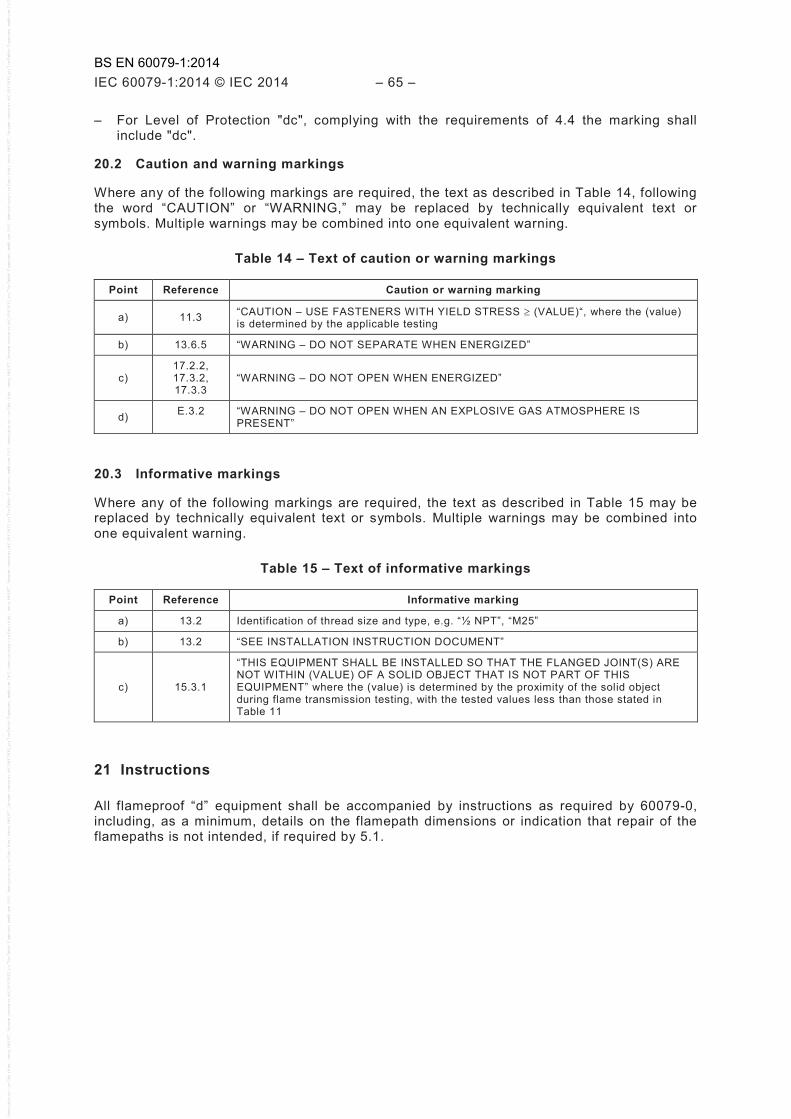
IEC 60079-1:2014 © IEC 2014 – 65 –
– For Level of Protection "dc", complying with the requirements of 4.4 the marking shall include "dc".
20.2 Caution and warning markings
Where any of the following markings are required, the text as described in Table 14, following the word “CAUTION” or “WARNING,” may be replaced by technically equivalent text or symbols. Multiple warnings may be combined into one equivalent warning.
Table 14 – Text of caution or warning markings
Point Reference Caution or warning marking
a) 11.3 “CAUTION – USE FASTENERS WITH YIELD STRESS ≥ (VALUE)“, where the (value) is determined by the applicable testing
b) 13.6.5 “WARNING – DO NOT SEPARATE WHEN ENERGIZED”
c) 17.2.2, 17.3.2, 17.3.3
“WARNING – DO NOT OPEN WHEN ENERGIZED”
d) E.3.2 “WARNING – DO NOT OPEN WHEN AN EXPLOSIVE GAS ATMOSPHERE IS PRESENT”
20.3 Informative markings
Where any of the following markings are required, the text as described in Table 15 may be replaced by technically equivalent text or symbols. Multiple warnings may be combined into one equivalent warning.
Table 15 – Text of informative markings
Point Reference Informative marking
a) 13.2 Identification of thread size and type, e.g. “½ NPT”, “M25”
b) 13.2 “SEE INSTALLATION INSTRUCTION DOCUMENT”
c) 15.3.1
“THIS EQUIPMENT SHALL BE INSTALLED SO THAT THE FLANGED JOINT(S) ARE NOT WITHIN (VALUE) OF A SOLID OBJECT THAT IS NOT PART OF THIS EQUIPMENT” where the (value) is determined by the proximity of the solid object during flame transmission testing, with the tested values less than those stated in Table 11
21 Instructions
All flameproof “d” equipment shall be accompanied by instructions as required by 60079-0, including, as a minimum, details on the flamepath dimensions or indication that repair of the flamepaths is not intended, if required by 5.1.
BS EN 60079-1:2014
– 66 – IEC 60079-1:2014 © IEC 2014
Annex A (normative)
Additional requirements for crimped ribbon elements and
multiple screen elements of breathing and draining devices
A.1 Crimped ribbon elements and multiple screen elements shall be constructed from cupro-nickel, stainless steel or other metal found suitable for the application. Aluminium, titanium, magnesium and their alloys shall not be used.
See 10.3 for limits on copper content.
A.2 Where the paths through the device can be specified in the drawings and measured in the complete device, an upper and lower tolerance limit for the path dimensions shall be specified and monitored in production.
A.3 Where Clause A.2 does not apply, the relevant requirements of Annex B shall apply.
A.4 The type tests of 15.4.4 shall be carried out with samples manufactured with not less than 90 % of the largest permitted gap dimensions.
BS EN 60079-1:2014

IEC 60079-1:2014 © IEC 2014 – 67 –
Annex B (normative)
Additional requirements for elements, with
non-measurable paths of breathing and draining devices
B.1 Sintered metal elements
B.1.1 Sintered metal elements shall be constructed from one of the following:
– stainless steel; – 90/10 copper-tin bronze; or – a specific metal or specific alloy found suitable for the application. Aluminium, titanium,
magnesium and their alloys shall not be used.
See 10.3 for limits on copper content.
B.1.2 The maximum bubble test pore size shall be determined by the method specified in ISO 4003.
B.1.3 The density of the sintered metal element shall be determined in accordance with ISO 2738.
B.1.4 Where determination of open porosity and/or fluid permeability of elements is required in connection with functional aspects of devices, measurements shall be made in accordance with ISO 2738 and ISO 4022.
B.1.5 Sintered metal elements shall be clearly identified in the documentation by declaring
a) the material in accordance with 10.3 and B.1.1, b) the maximum bubble test pore size in micrometers in accordance with B.1.2, c) the minimum density in accordance with B.1.3, d) the minimum thickness, and e) where appropriate, the fluid permeability and open porosity in accordance with B.1.4.
B.2 Pressed metal wire elements
B.2.1 Pressed metal wire elements shall be constructed from stainless steel wire braid or another specified metal found suitable for the application.
See 10.3 for limits on copper content.
Aluminium, titanium, magnesium and their alloys shall not be used. Manufacture shall start from a wire braid which is compressed in a die to form an homogeneous matrix.
B.2.2 In order to evaluate the density, the wire diameter shall be specified. Information shall also be given on the mass, length of wire braid, thickness of the element, and mesh size. The ratio between the mass of the element and the mass of an identical volume of the same solid metal shall be between 0,4 and 0,6.
B.2.3 The maximum bubble test pore size shall be determined by the method specified in ISO 4003.
B.2.4 The density of the element shall be determined in accordance with ISO 2738.
BS EN 60079-1:2014

– 68 – IEC 60079-1:2014 © IEC 2014
B.2.5 Where determination of open porosity and/or fluid permeability is required in connection with functional aspects of elements, measurements shall be made in accordance with ISO 2738 and ISO 4022.
B.2.6 Metal wire elements shall be clearly identified in the documentation by declaring:
a) the material in accordance with 10.3 and B.2.1, b) the maximum bubble test pore size in micrometers in accordance with B.2.3, c) the minimum density in accordance with B.2.4, d) the dimensions, including tolerances, e) the original wire diameter, and f) where appropriate, the fluid permeability and open porosity in accordance with B.2.5.
B.3 Metal foam elements
B.3.1 Metal foam elements shall be produced by coating a reticulated polyurethane foam with nickel, removing the polyurethane by thermal decomposition, converting the nickel into a nickel-chrome alloy, for example, by gaseous diffusion, and compressing the material as necessary.
B.3.2 Metal foam elements shall contain at least 15 % chromium by mass.
B.3.3 The maximum bubble test pore size shall be determined by the method specified in ISO 4003.
B.3.4 The density of the element shall be determined in accordance with ISO 2738.
B.3.5 Where determination of open porosity and/or fluid permeability is required in connection with functional aspects of elements, measurements shall be made in accordance with ISO 2738 and ISO 4022.
B.3.6 Metal foam elements shall be clearly defined in the documentation by declaring:
a) the material, in accordance with 10.3, B.3.1 and B.3.2, b) the maximum bubble test pore size in micrometers in accordance with B.3.3, c) the minimum thickness, d) the minimum density, and e) where appropriate, the open porosity and fluid permeability in accordance with B.3.5.
BS EN 60079-1:2014

IEC 60079-1:2014 © IEC 2014 – 69 –
Annex C (normative)
Additional requirements for flameproof entry devices
C.1 General
This annex contains specific requirements which apply, in addition to those in IEC 60079-0, to the construction and testing of flameproof entry devices. Entry devices include cable glands, conduit sealing devices, Ex blanking elements, Ex thread adaptors, and bushings.
C.2 Constructional requirements
C.2.1 Sealing methods
C.2.1.1 Cable glands and conduit sealing devices with elastomeric sealing rings
C.2.1.1.1 If a cable gland or conduit sealing device can accept any sealing ring with the same outside diameter but with different internal dimensions, the ring shall have a minimum uncompressed axial sealing height (i.e. gap length) between the body of the gland and sealing ring and between the sealing ring and the cable of
– 20 mm, for circular cables of diameter not greater than 20 mm, and for non-circular cables of perimeter not greater than 60 mm, or
– 25 mm, for circular cables of diameter greater than 20 mm, and for non-circular cables of perimeter greater than 60 mm.
C.2.1.1.2 If a cable gland or conduit sealing device can accept only one specific elastomeric sealing ring, this ring shall have a minimum uncompressed axial sealing height of 5 mm between body of gland and sealing ring and between cable and sealing ring.
C.2.1.2 Cable glands sealed with setting compound
The minimum length of the compound shall be 20 mm when installed.
The manufacturer shall specify:
a) the maximum diameter over cores of the cable that the gland is intended to accept; and
b) the maximum numbers of cores that can pass through the compound.
These specified values shall ensure that, throughout the required 20 mm compound length, at least 20 % of that cross-sectional area is filled with compound.
The cable gland shall be capable of being fitted and removed from electrical equipment without disturbing the compound seal after the specified curing period of the compound.
The filling compound and appropriate installation instructions shall be provided with the cable gland.
C.2.1.3 Conduit sealing devices with setting compound
The minimum length of the compound shall be 20 mm when installed.
The manufacturer shall specify the maximum numbers of cores that can pass through the compound.
BS EN 60079-1:2014

– 70 – IEC 60079-1:2014 © IEC 2014
These specified values shall ensure that, throughout the required 20 mm compound length, at least 20 % of that cross-sectional area is filled with compound.
The filling compound and appropriate installation instructions shall be provided with the conduit sealing device.
C.2.1.4 Bushings
Bushings may contain one or more conductors. When they are correctly assembled and mounted in the walls of the enclosure, all joint widths, gaps or cemented joints shall conform with the relevant requirements of Clauses 5, 6 and C.2.2. The documentation shall specify the maximum numbers of cores that can pass through the compound.
NOTE To provide adequate strength, bushing designs generally provide, throughout the required cemented joint length, at least 20 % of that cross-sectional area filled with compound.
When the bushing is formed by moulding insulation on metallic parts, the requirements of 5.2, 5.3 and 5.4 do not apply, but Clause 6 is applicable with the required non-transmission test performed with the bushing installed in a representative enclosure of the intended maximum end-application volume, with a minimum conductor length as specified in the documentation. The insulation material itself can contribute to the mechanical strength of the enclosure.
When the bushing includes parts assembled with adhesive, this is considered as a cement if it complies with the requirements of Clause 6 with the required non-transmission test performed with the bushing installed in a representative enclosure of the intended maximum end-application volume, with a minimum conductor length as specified in the documentation. Should this not be the case, the requirements of 5.2.1, 5.3 and 5.4 are applicable.
The parts of bushings outside the flameproof enclosure shall be protected in accordance with IEC 60079-0.
Bushings specific to a flameproof enclosure shall satisfy the type tests and routine tests for that enclosure.
Ex component bushings shall be submitted to a type test for resistance to pressure carried out by means of a static pressure test as specified in 15.2.3.2 at the following values:
– 2 000 kPa for electrical equipment of Group I; – 3 000 kPa for electrical equipment of Group II.
These bushings shall be subject to a routine pressure test as specified in 16.1, except where the assembly procedure used is described in the manufacturer's documentation and is such as to ensure consistency in the manufactured products.
If the cemented joint is judged satisfactory with or without leakage, then the schedule of limitations of the Ex component certificate shall specify the maximum intended enclosure volume and the minimum specified conductor length.
C.2.2 Flameproof joints
C.2.2.1 Threaded joints
Threads forming part of a flameproof joint shall comply with the relevant requirements of 5.3 and shall be one of the following:
– metric threads with a tolerance Class of 6g/6H or better according to ISO 965-1 and ISO 965-3, and any chamfer or undercut of an internal thread is limited to a maximum depth of 2 mm from the external surface;
– tapered threads shall conform to the NPT requirements of ANSI/ASME B1.20.1;
BS EN 60079-1:2014
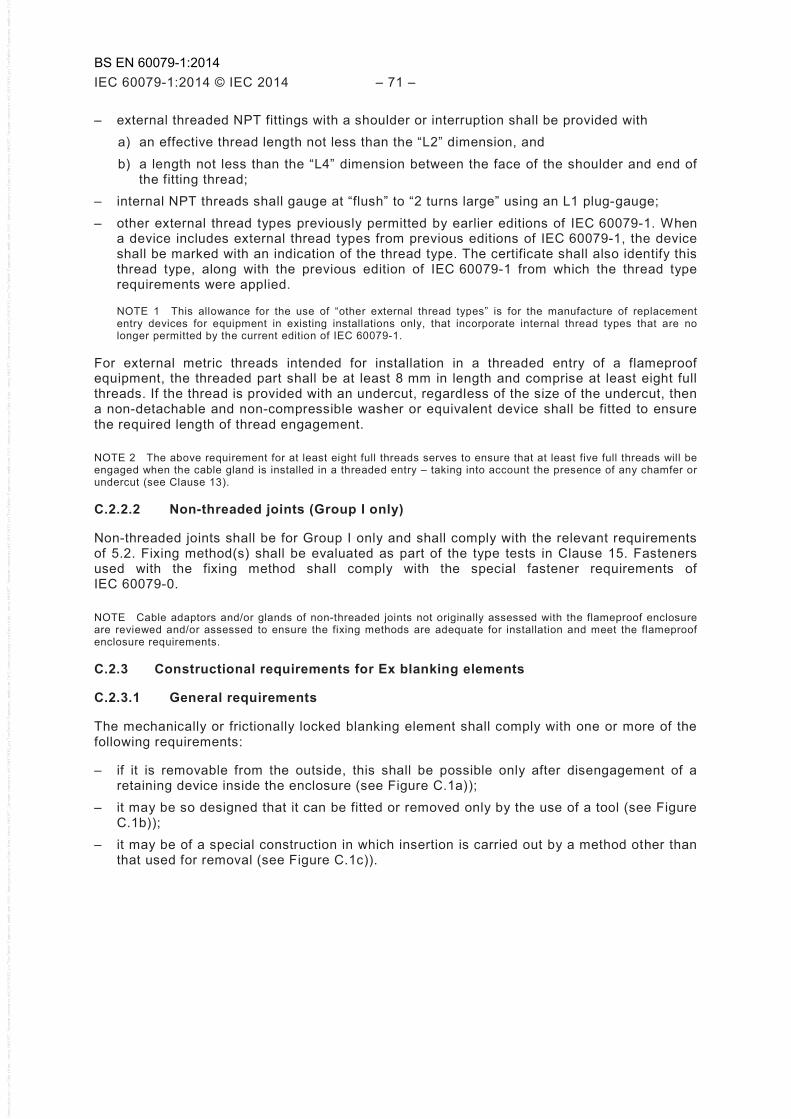
IEC 60079-1:2014 © IEC 2014 – 71 –
– external threaded NPT fittings with a shoulder or interruption shall be provided with a) an effective thread length not less than the “L2” dimension, and b) a length not less than the “L4” dimension between the face of the shoulder and end of
the fitting thread; – internal NPT threads shall gauge at “flush” to “2 turns large” using an L1 plug-gauge; – other external thread types previously permitted by earlier editions of IEC 60079-1. When
a device includes external thread types from previous editions of IEC 60079-1, the device shall be marked with an indication of the thread type. The certificate shall also identify this thread type, along with the previous edition of IEC 60079-1 from which the thread type requirements were applied.
NOTE 1 This allowance for the use of “other external thread types” is for the manufacture of replacement entry devices for equipment in existing installations only, that incorporate internal thread types that are no longer permitted by the current edition of IEC 60079-1.
For external metric threads intended for installation in a threaded entry of a flameproof equipment, the threaded part shall be at least 8 mm in length and comprise at least eight full threads. If the thread is provided with an undercut, regardless of the size of the undercut, then a non-detachable and non-compressible washer or equivalent device shall be fitted to ensure the required length of thread engagement.
NOTE 2 The above requirement for at least eight full threads serves to ensure that at least five full threads will be engaged when the cable gland is installed in a threaded entry – taking into account the presence of any chamfer or undercut (see Clause 13).
C.2.2.2 Non-threaded joints (Group I only)
Non-threaded joints shall be for Group I only and shall comply with the relevant requirements of 5.2. Fixing method(s) shall be evaluated as part of the type tests in Clause 15. Fasteners used with the fixing method shall comply with the special fastener requirements of IEC 60079-0.
NOTE Cable adaptors and/or glands of non-threaded joints not originally assessed with the flameproof enclosure are reviewed and/or assessed to ensure the fixing methods are adequate for installation and meet the flameproof enclosure requirements.
C.2.3 Constructional requirements for Ex blanking elements
C.2.3.1 General requirements
The mechanically or frictionally locked blanking element shall comply with one or more of the following requirements:
– if it is removable from the outside, this shall be possible only after disengagement of a retaining device inside the enclosure (see Figure C.1a));
– it may be so designed that it can be fitted or removed only by the use of a tool (see Figure C.1b));
– it may be of a special construction in which insertion is carried out by a method other than that used for removal (see Figure C.1c)).
BS EN 60079-1:2014
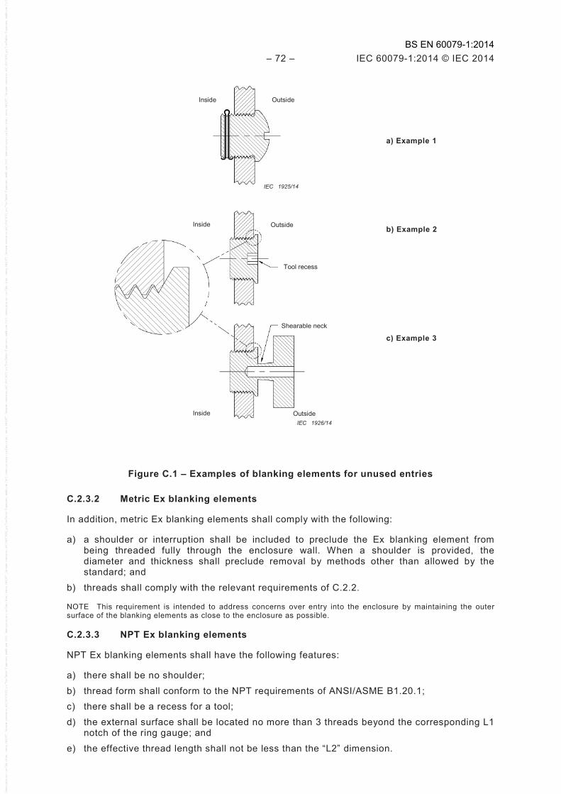
– 72 – IEC 60079-1:2014 © IEC 2014
Inside Outside
IEC 1925/14
a) Example 1
Inside Outside
Tool recess
Shearable neck
Inside Outside IEC 1926/14
b) Example 2
c) Example 3
Figure C.1 – Examples of blanking elements for unused entries
C.2.3.2 Metric Ex blanking elements
In addition, metric Ex blanking elements shall comply with the following:
a) a shoulder or interruption shall be included to preclude the Ex blanking element from being threaded fully through the enclosure wall. When a shoulder is provided, the diameter and thickness shall preclude removal by methods other than allowed by the standard; and
b) threads shall comply with the relevant requirements of C.2.2.
NOTE This requirement is intended to address concerns over entry into the enclosure by maintaining the outer surface of the blanking elements as close to the enclosure as possible.
C.2.3.3 NPT Ex blanking elements
NPT Ex blanking elements shall have the following features:
a) there shall be no shoulder; b) thread form shall conform to the NPT requirements of ANSI/ASME B1.20.1; c) there shall be a recess for a tool; d) the external surface shall be located no more than 3 threads beyond the corresponding L1
notch of the ring gauge; and e) the effective thread length shall not be less than the “L2” dimension.
BS EN 60079-1:2014
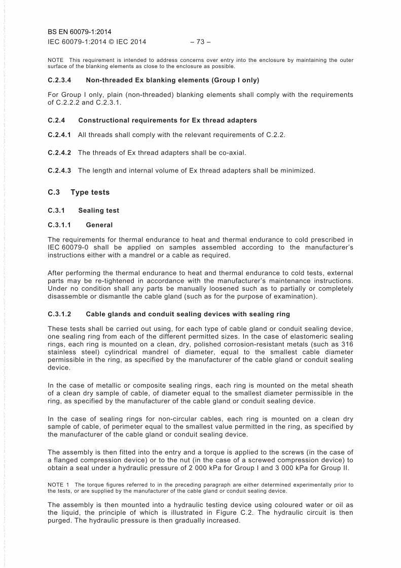
IEC 60079-1:2014 © IEC 2014 – 73 –
NOTE This requirement is intended to address concerns over entry into the enclosure by maintaining the outer surface of the blanking elements as close to the enclosure as possible.
C.2.3.4 Non-threaded Ex blanking elements (Group I only)
For Group I only, plain (non-threaded) blanking elements shall comply with the requirements of C.2.2.2 and C.2.3.1.
C.2.4 Constructional requirements for Ex thread adapters
C.2.4.1 All threads shall comply with the relevant requirements of C.2.2.
C.2.4.2 The threads of Ex thread adapters shall be co-axial.
C.2.4.3 The length and internal volume of Ex thread adapters shall be minimized.
C.3 Type tests
C.3.1 Sealing test
C.3.1.1 General
The requirements for thermal endurance to heat and thermal endurance to cold prescribed in IEC 60079-0 shall be applied on samples assembled according to the manufacturer’s instructions either with a mandrel or a cable as required.
After performing the thermal endurance to heat and thermal endurance to cold tests, external parts may be re-tightened in accordance with the manufacturer’s maintenance instructions. Under no condition shall any parts be manually loosened such as to partially or completely disassemble or dismantle the cable gland (such as for the purpose of examination).
C.3.1.2 Cable glands and conduit sealing devices with sealing ring
These tests shall be carried out using, for each type of cable gland or conduit sealing device, one sealing ring from each of the different permitted sizes. In the case of elastomeric sealing rings, each ring is mounted on a clean, dry, polished corrosion-resistant metals (such as 316 stainless steel) cylindrical mandrel of diameter, equal to the smallest cable diameter permissible in the ring, as specified by the manufacturer of the cable gland or conduit sealing device.
In the case of metallic or composite sealing rings, each ring is mounted on the metal sheath of a clean dry sample of cable, of diameter equal to the smallest diameter permissible in the ring, as specified by the manufacturer of the cable gland or conduit sealing device.
In the case of sealing rings for non-circular cables, each ring is mounted on a clean dry sample of cable, of perimeter equal to the smallest value permitted in the ring, as specified by the manufacturer of the cable gland or conduit sealing device.
The assembly is then fitted into the entry and a torque is applied to the screws (in the case of a flanged compression device) or to the nut (in the case of a screwed compression device) to obtain a seal under a hydraulic pressure of 2 000 kPa for Group I and 3 000 kPa for Group II.
NOTE 1 The torque figures referred to in the preceding paragraph are either determined experimentally prior to the tests, or are supplied by the manufacturer of the cable gland or conduit sealing device.
The assembly is then mounted into a hydraulic testing device using coloured water or oil as the liquid, the principle of which is illustrated in Figure C.2. The hydraulic circuit is then purged. The hydraulic pressure is then gradually increased.
BS EN 60079-1:2014
– 74 – IEC 60079-1:2014 © IEC 2014
The sealing is considered satisfactory if the blotting paper is free from any trace of leakage when the pressure has been maintained at 2 000 kPa for Group I or 3 000 kPa for Group II, for at least 10 s.
NOTE 2 In order to maintain the test pressure, it can be necessary to seal all the joints of the cable gland or conduit sealing device mounted in the test device, other than those associated with the sealing ring under test. When a sample of metal-sheathed cable is used, it can be necessary to avoid the application of pressure to the ends of the conductors or to the interior of the cable.
Key
1 hydraulic pump 6 sealing ring
2 pressure gauge 7 mandrel/metal-sheathed cable
3 hose 8 compression component
4 blotting paper 9 retaining clamp
5 adapter
Figure C.2 – Device for the sealing tests for cable glands
C.3.1.3 Cable glands sealed with setting compound
For each size of cable gland, the test shall be carried out using metal mandrels, the number and diameter of which equate to the maximum diameter over cores with the maximum number of cores specified by the manufacturer in accordance with the requirements of C.2.1.2.
The setting compound is prepared following the manufacturer's instructions and then introduced into the appropriate volume. It is allowed to harden for the appropriate time.
The assembly is then mounted into the hydraulic testing device, defined in C.3.1.2 and the same procedure is applied. The acceptance criteria are also the same.
C.3.1.4 Conduit sealing devices sealed with setting compound
For each size of conduit sealing device, the test shall be carried out using metal mandrels, the number and diameter of which equate to the maximum number of cores specified by the manufacturer in accordance with the requirements of C.2.1.3.
The setting compound is prepared following the manufacturer's instructions and then introduced into the appropriate volume. It is allowed to harden for the appropriate time.
The assembly is then mounted into the hydraulic testing device, defined in C.3.1.2 and the same procedure is applied. The acceptance criteria are also the same.
C.3.2 Test of mechanical strength
C.3.2.1 Cable glands with a threaded compression element
A torque of twice that required in the sealing test shall be applied to the compression element; however, the value of this torque, expressed in Nm, shall always be at least three times the
1 2 3 5 6 7
8 9 4 IEC 1927/14
BS EN 60079-1:2014
IEC 60079-1:2014 © IEC 2014 – 75 –
value in millimetres of the maximum permissible cable diameter when the cable gland is designed for circular cables or equal to the value in millimetres of the maximum permissible cable perimeter when the cable gland is designed for non-circular cables.
The cable gland is then dismantled and its parts are examined.
C.3.2.2 Cable glands with a compression element fixed by screws
A torque of twice that required in the sealing test shall be applied to the compression element screws; however, the value of this torque shall always be at least equal to the following values:
M6: 10 Nm M12: 60 Nm M8: 20 Nm M14: 100 Nm M10: 40 Nm M16: 150 Nm
The cable gland is then dismantled and its parts are examined.
C.3.2.3 Cable glands sealed with setting compound
In the case of threaded glands, a torque in Nm equal to the minimum value specified in C.3.2.1 shall be applied to the gland when screwed into a steel test block having a suitable threaded hole.
The cable gland is then dismantled and its parts are examined.
C.3.2.4 Acceptance criteria
The tests C.3.2.1 to C.3.2.3 shall be considered to be satisfactory if no damage is found to any of the parts of the cable gland.
NOTE Any damage to the sealing ring is disregarded, as the test is intended to show that the mechanical strength of the cable gland is sufficient to withstand the conditions of use.
C.3.3 Type tests for Ex blanking elements
C.3.3.1 Torque test
A sample Ex blanking element of each size shall be screwed into a steel test-block containing a threaded entry hole of size and form appropriate to the device under test. The sample shall be tightened to a torque at least equivalent to the appropriate torque given in Column 2 of Table C.1 or C.2, using a suitable tool. The test shall be deemed to be satisfactory if the correct thread engagement has been achieved and if, when dismantled, no damage invalidating the type of protection is found, except for failure of the shearable neck of a Figure C.1c – Example 3 plug which is required. Figure C.1b – Example 2 plugs shall be capable of being removed only by the appropriate tool.
Metric Ex blanking elements of Figure C.1b – Example 2 shall then be subjected to a further test at a torque at least equivalent to the appropriate torque given in Column 3 of Table C.1, and shall be deemed to be satisfactory if the shoulder has not pulled fully into the thread.
C.3.3.2 Over-pressure test
The Ex blanking element shall be submitted to a type test for resistance to pressure carried out by means of a static pressure test as specified in 15.2.3.2 at the following values:
– 2 000 kPa for electrical equipment of Group I; – 3 000 kPa for electrical equipment of Group II.
BS EN 60079-1:2014
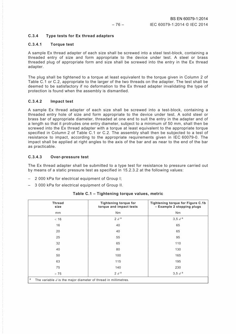
– 76 – IEC 60079-1:2014 © IEC 2014
C.3.4 Type tests for Ex thread adapters
C.3.4.1 Torque test
A sample Ex thread adapter of each size shall be screwed into a steel test-block, containing a threaded entry of size and form appropriate to the device under test. A steel or brass threaded plug of appropriate form and size shall be screwed into the entry in the Ex thread adapter.
The plug shall be tightened to a torque at least equivalent to the torque given in Column 2 of Table C.1 or C.2, appropriate to the larger of the two threads on the adapter. The test shall be deemed to be satisfactory if no deformation to the Ex thread adapter invalidating the type of protection is found when the assembly is dismantled.
C.3.4.2 Impact test
A sample Ex thread adapter of each size shall be screwed into a test-block, containing a threaded entry hole of size and form appropriate to the device under test. A solid steel or brass bar of appropriate diameter, threaded at one end to suit the entry in the adapter and of a length so that it protrudes one entry diameter, subject to a minimum of 50 mm, shall then be screwed into the Ex thread adapter with a torque at least equivalent to the appropriate torque specified in Column 2 of Table C.1 or C.2. The assembly shall then be subjected to a test of resistance to impact, according to the appropriate requirements given in IEC 60079-0. The impact shall be applied at right angles to the axis of the bar and as near to the end of the bar as practicable.
C.3.4.3 Over-pressure test
The Ex thread adapter shall be submitted to a type test for resistance to pressure carried out by means of a static pressure test as specified in 15.2.3.2 at the following values:
– 2 000 kPa for electrical equipment of Group I; – 3 000 kPa for electrical equipment of Group II.
Table C.1 – Tightening torque values, metric
Thread size
Tightening torque for torque and impact tests
Tightening torque for Figure C.1b – Example 2 stopping plugs
mm Nm Nm
< 16 2 d a 3,5 d a
16 40 65
20 40 65
25 55 95
32 65 110
40 80 130
50 100 165
63 115 195
75 140 230
> 75 2 d a 3,5 d a a The variable d is the major diameter of thread in millimetres.
BS EN 60079-1:2014
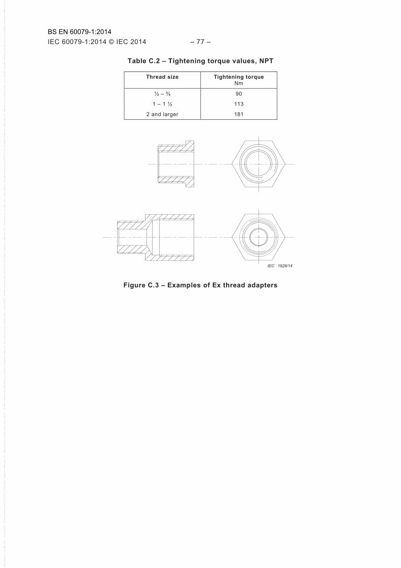
IEC 60079-1:2014 © IEC 2014 – 77 –
Table C.2 – Tightening torque values, NPT
Thread size Tightening torque Nm
½ – ¾ 90
1 – 1 ½ 113
2 and larger 181
IEC 1928/14
Figure C.3 – Examples of Ex thread adapters
BS EN 60079-1:2014

– 78 – IEC 60079-1:2014 © IEC 2014
Annex D (normative)
Empty flameproof enclosures as Ex components
D.1 General
The purpose of an Ex component enclosure certificate for empty enclosures is to enable a manufacturer of flameproof enclosures to obtain a certificate without the internal equipment being defined, so as to enable the empty enclosure to be made available to third parties for incorporation into a full equipment certificate without the need for repetition of all the type tests for flameproof enclosures “d” as required by IEC 60079-1 and IEC 60079-0. When a certificate concerning the full equipment is required, an Ex component enclosure certificate for the empty enclosure is not necessary.
D.2 Introductory remarks
The requirements for an Ex component enclosure certificate for an empty enclosure are contained in this annex. This does not eliminate the need for a subsequent equipment certificate, but it is intended to facilitate such a certificate.
The Ex component enclosure manufacturer shall be responsible for ensuring that each and every unit supplied
a) is identical in construction with the original design as detailed in the documents mentioned in the Ex component enclosure certificate,
b) has been subjected to such routine overpressure testing as is required, and c) meets the requirements of the applicable schedule of limitations imposed by the Ex
component enclosure certificate.
D.3 Ex component enclosure requirements
D.3.1 Ex component enclosures shall comply with the requirements, as applicable, of IEC 60079-0 and of this standard.
D.3.2 Ex component enclosures shall consist of a basically simple geometry of only square, rectangular, or cylindrical cross-section with taper not exceeding 10 %.
NOTE Simple geometry is considered to include those constructions in which major dimensions do not exceed any other dimension by 4:1 for Group I, IIA and IIB, or do not exceed any other dimension by 2:1 for Group IIC.
D.3.3 Enclosures for rotating machines shall not be evaluated as Ex component enclosures.
NOTE “Machines” are taken to mean electric motors which substantially fill the enclosure.
D.3.4 Ex component enclosures shall be provided with adequate means for the mounting and location of internal components.
D.3.5 No holes, whether for mechanical or electrical purposes, and whether blind or clear, shall be drilled in the Ex component enclosure other than those permitted by the Ex component enclosure certificate.
D.3.6 For Group I, IIA and IIB Ex component enclosures, the reference pressure is determined according to 15.2.2, with modifications to the test sample as follows:
BS EN 60079-1:2014
IEC 60079-1:2014 © IEC 2014 – 79 –
– when no major dimension exceeds any other major dimension by more than 2:1, no modification is needed;
– for all other permitted constructions, a solid obstruction (baffle plate) of approximately 80 % of the cross-sectional area shall be located centrally on the minor axis, and located approximately two-thirds of the way along the major axis. The solid obstruction shall reasonably replicate the cross-section of the enclosure.
For Group IIC Ex component enclosures, the reference pressure is determined according to 15.2.2, with a solid obstruction (baffle plate) of approximately 60 % of the cross-sectional area located centrally on the minor axis, and located approximately two-thirds of the way along the major axis. The solid obstruction shall reasonably replicate the cross-section of the enclosure.
When the sample is required to be modified by inclusion of the solid obstruction, ignition sources and pressure recording devices shall be positioned on both sides of the solid obstruction to simultaneously measure the resultant pressures.
D.3.7 Ex component enclosures shall withstand an overpressure type test with the maximum number of apertures of the maximum sizes at a pressure which shall be equal to 1,5 times the peak explosion pressure (reference pressure) measured according to 15.2.2 with the Ex component enclosure empty, and with the entries closed by suitable means.
Routine tests are not required for Ex component enclosures when the prescribed type test has been made at a static pressure of four times the reference pressure. However, Ex component enclosures of welded construction shall, in every case, be submitted to the routine test.
The routine test shall consist of either a dynamic test with, inside and outside the Ex component enclosure, the appropriate explosive mixture specified in 15.2.2 (for the determination of explosion pressure) at a pressure of 1,5 times atmospheric pressure; or a static test at a pressure of at least 350 kPa and not less than 1,5 times the reference pressure.
D.3.8 The enclosure shall be marked in accordance with the requirements for marking of Ex components given in IEC 60079-0, but shall be internal and not required to be permanent. The Ex marking string shall not be marked externally. Only the manufacturer's name and enclosure identifier information (such as type or serial number) may be marked external to the enclosure. This marking need not be permanent.
These markings may be omitted if the Ex component enclosure manufacturer is also intended to be the holder of the equipment certificate, and indicated as such in the Ex component certificate schedule of limitations.
D.3.9 Provision shall be made for the mounting of external marking for equipment according to IEC 60079-0.
D.3.10 The following information shall be given in the Ex component enclosure certificate as part of the schedule of limitations:
a) the maximum number of apertures, their maximum sizes and their positions shall be addressed through direct statement or reference to a drawing number;
b) oil-filled circuit-breakers and contactors shall not be used;
c) (for ambient ranges other than –20 °C to +40 °C) the ambient range; d) (if applicable per D.3.8) indication that the Ex component enclosure manufacturer is
intended to be the only holder of the related equipment certificate(s); e) (for Group I, IIA and IIB Ex component enclosures) the content of the Ex component
enclosure equipment may be placed in any arrangement, provided that an area of at least 20 % of each cross-sectional area remains free to permit an unimpeded gas flow and, therefore, unrestricted development of an explosion. Separate relief areas may be aggregated provided that each area has a minimum dimension in any direction of 12,5 mm;
BS EN 60079-1:2014
– 80 – IEC 60079-1:2014 © IEC 2014
f) (for Group IIC Ex component enclosures) the content of the Ex component enclosure equipment may be placed in any arrangement provided that an area of at least 40 % of each cross-sectional area remains free to permit unimpeded gas flow and, therefore, unrestricted development of an explosion. Separate relief areas may be aggregated provided that each area has a minimum dimension in any direction of 12,5 mm; and
g) any additional limitation required for the particular construction, e.g. maximum operating temperature of the window.
D.4 Utilization of an Ex component enclosure certificate to prepare an equipment certificate
D.4.1 Procedure
Enclosures which have an Ex component enclosure certificate may be considered for incorporation in equipment certificates with IEC 60079-0 and this standard, normally without repetition of application of those requirements already applied to the Ex component enclosure, subject to consideration of the schedule of limitations detailed in D.3.10.
Documents shall be prepared for an equipment certificate depicting the specified equipment, any permitted substitutions or omissions, together with the mounting conditions within the Ex component enclosure, so that compliance can be verified with the schedule of limitations of the Ex component enclosure certificate.
Any hole permitted in accordance with the Ex component enclosure certificate may be provided either by the Ex component enclosure manufacturer, or by the equipment manufacturer through agreement between the equipment manufacturer and the Ex component enclosure manufacturer.
The continuous effects of devices, such as rotating devices, which can create significant turbulence that may result in an increase in reference pressure shall be considered.
D.4.2 Application of the schedule of limitations
In addition to compliance with the schedule of limitations, all application issues shall be considered and determined to comply with the applicable requirements of IEC 60079-0 and this standard.
BS EN 60079-1:2014
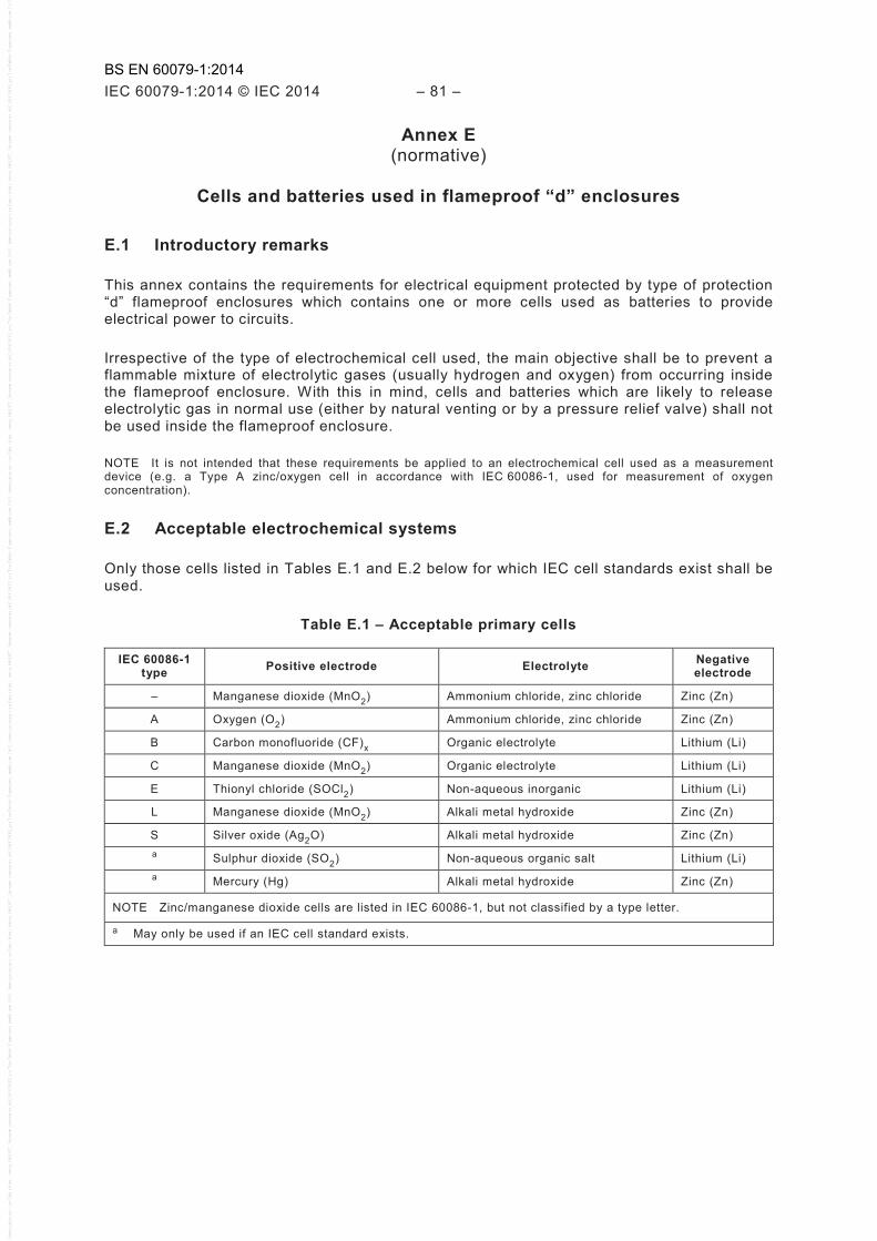
IEC 60079-1:2014 © IEC 2014 – 81 –
Annex E (normative)
Cells and batteries used in flameproof “d” enclosures
E.1 Introductory remarks
This annex contains the requirements for electrical equipment protected by type of protection “d” flameproof enclosures which contains one or more cells used as batteries to provide electrical power to circuits.
Irrespective of the type of electrochemical cell used, the main objective shall be to prevent a flammable mixture of electrolytic gases (usually hydrogen and oxygen) from occurring inside the flameproof enclosure. With this in mind, cells and batteries which are likely to release electrolytic gas in normal use (either by natural venting or by a pressure relief valve) shall not be used inside the flameproof enclosure.
NOTE It is not intended that these requirements be applied to an electrochemical cell used as a measurement device (e.g. a Type A zinc/oxygen cell in accordance with IEC 60086-1, used for measurement of oxygen concentration).
E.2 Acceptable electrochemical systems
Only those cells listed in Tables E.1 and E.2 below for which IEC cell standards exist shall be used.
Table E.1 – Acceptable primary cells
IEC 60086-1 type Positive electrode Electrolyte Negative
electrode
– Manganese dioxide (MnO2) Ammonium chloride, zinc chloride Zinc (Zn)
A Oxygen (O2) Ammonium chloride, zinc chloride Zinc (Zn)
B Carbon monofluoride (CF)x Organic electrolyte Lithium (Li)
C Manganese dioxide (MnO2) Organic electrolyte Lithium (Li)
E Thionyl chloride (SOCl2) Non-aqueous inorganic Lithium (Li)
L Manganese dioxide (MnO2) Alkali metal hydroxide Zinc (Zn)
S Silver oxide (Ag2O) Alkali metal hydroxide Zinc (Zn) a Sulphur dioxide (SO2) Non-aqueous organic salt Lithium (Li) a Mercury (Hg) Alkali metal hydroxide Zinc (Zn)
NOTE Zinc/manganese dioxide cells are listed in IEC 60086-1, but not classified by a type letter.
a May only be used if an IEC cell standard exists.
BS EN 60079-1:2014
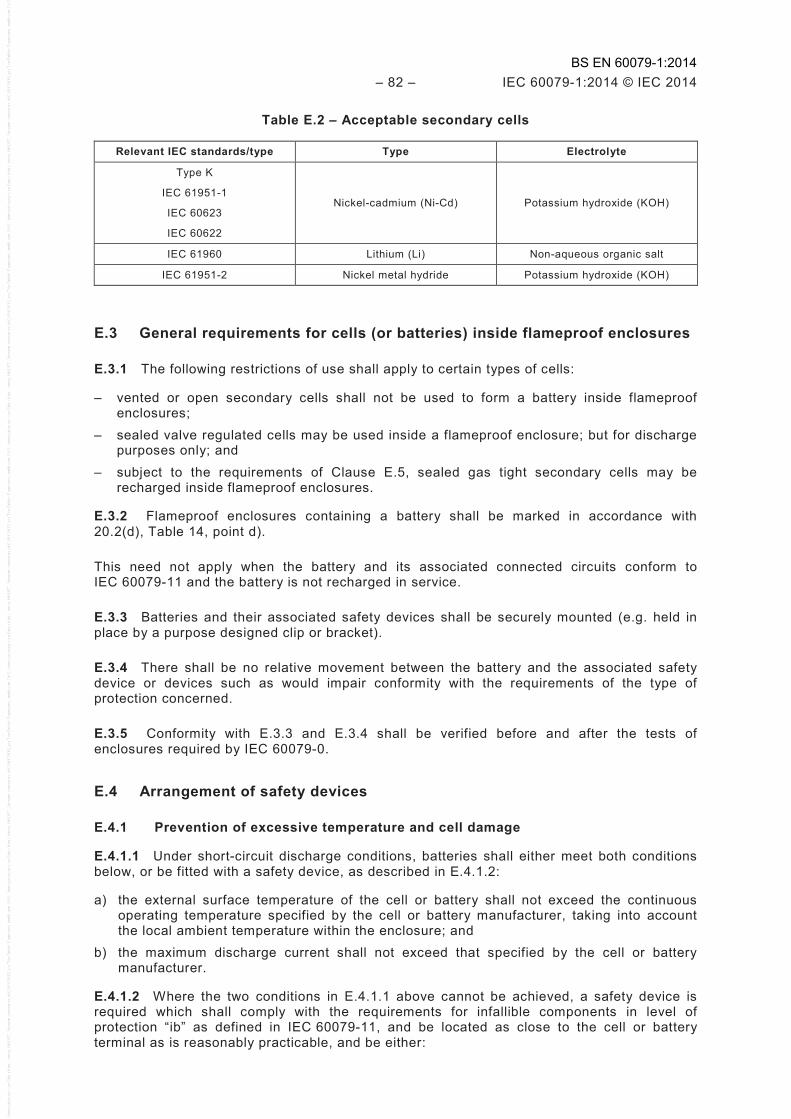
– 82 – IEC 60079-1:2014 © IEC 2014
Table E.2 – Acceptable secondary cells
Relevant IEC standards/type Type Electrolyte
Type K
IEC 61951-1
IEC 60623
IEC 60622
Nickel-cadmium (Ni-Cd) Potassium hydroxide (KOH)
IEC 61960 Lithium (Li) Non-aqueous organic salt
IEC 61951-2 Nickel metal hydride Potassium hydroxide (KOH)
E.3 General requirements for cells (or batteries) inside flameproof enclosures
E.3.1 The following restrictions of use shall apply to certain types of cells:
– vented or open secondary cells shall not be used to form a battery inside flameproof enclosures;
– sealed valve regulated cells may be used inside a flameproof enclosure; but for discharge purposes only; and
– subject to the requirements of Clause E.5, sealed gas tight secondary cells may be recharged inside flameproof enclosures.
E.3.2 Flameproof enclosures containing a battery shall be marked in accordance with 20.2(d), Table 14, point d).
This need not apply when the battery and its associated connected circuits conform to IEC 60079-11 and the battery is not recharged in service.
E.3.3 Batteries and their associated safety devices shall be securely mounted (e.g. held in place by a purpose designed clip or bracket).
E.3.4 There shall be no relative movement between the battery and the associated safety device or devices such as would impair conformity with the requirements of the type of protection concerned.
E.3.5 Conformity with E.3.3 and E.3.4 shall be verified before and after the tests of enclosures required by IEC 60079-0.
E.4 Arrangement of safety devices
E.4.1 Prevention of excessive temperature and cell damage
E.4.1.1 Under short-circuit discharge conditions, batteries shall either meet both conditions below, or be fitted with a safety device, as described in E.4.1.2:
a) the external surface temperature of the cell or battery shall not exceed the continuous operating temperature specified by the cell or battery manufacturer, taking into account the local ambient temperature within the enclosure; and
b) the maximum discharge current shall not exceed that specified by the cell or battery manufacturer.
E.4.1.2 Where the two conditions in E.4.1.1 above cannot be achieved, a safety device is required which shall comply with the requirements for infallible components in level of protection “ib” as defined in IEC 60079-11, and be located as close to the cell or battery terminal as is reasonably practicable, and be either:
BS EN 60079-1:2014

IEC 60079-1:2014 © IEC 2014 – 83 –
– a resistor or current-limiting device, which limits the current to the maximum continuous withdrawal current specified by the battery manufacturer; or
– a fuse conforming with the IEC 60127 series, selected so that the fusing characteristic prevents the maximum withdrawal current and allowable duration specified by the battery manufacturer from being exceeded. Where the fuse is of the replaceable type, a label shall be provided adjacent to the fuse holder, specifying the type of fuse to be used.
The rating of the resistor or current-limiting device shall be based on the voltage of the cell or battery.
E.4.2 Prevention of cell polarity reversal or reverse charging by another cell in the same battery
E.4.2.1 Where batteries are used having
a) a capacity of 1,5 Ah or less (at a 1 h discharge rate), and b) a volume less than 1 % of the free volume of the enclosure,
no additional protection need be fitted to prevent the release of electrolytic gas by polarity reversal, or reverse charging of a cell by other cells in the same battery.
E.4.2.2 Where batteries are used having a capacity and/or volume which exceed the above values, arrangements shall be incorporated to prevent cell polarity reversal or reverse charging of a cell by others within the battery.
Two examples of how this may be achieved are given in below:
– monitoring the cell voltage across a cell (or a few cells) and cutting off the supply if the voltage decreases below the minimum voltage specified by the cell manufacturer; or
NOTE 1 Such protection is often used to prevent cells going into a state of “deep discharge”. If an attempt is made to monitor too many cells connected in series, the protection will sometimes not function reliably due to tolerances in individual cell voltages and the protection circuit. Generally, monitoring of more than six cells (in series) by one protection unit is not effective.
– using shunt diodes connected so as to limit the reverse polarity voltage across each cell. For example, the protective arrangement for a battery of three cells connected in series is as shown in Figure E.1.
+Ve –Ve
IEC 1929/14
Figure E.1 – Fitting of diode arrangement for three cells in series
For this protective arrangement to be effective, the forward voltage drop across each diode used to prevent reverse charging of a cell shall not exceed the safe reverse charge voltage of that cell.
NOTE 2 Silicon diodes are considered suitable to meet this requirement.
E.4.3 Prevention of inadvertent charging of a battery by other voltage sources in the enclosure
Where batteries are used having
a) a capacity of 1,5 Ah or less (at a 1 h discharge rate), and
BS EN 60079-1:2014

– 84 – IEC 60079-1:2014 © IEC 2014
b) a volume less than 1 % of the free volume of the enclosure,
no additional protection need be fitted to prevent the release of electrolytic gas by recharging currents.
Where there is another voltage source in the same enclosure (including other batteries), the battery and its associated circuits shall be protected against charging by other than the circuit specifically designed to do so. For example:
– separating the battery and its associated circuits from all other voltage source(s) inside the enclosure, using the clearance and creepage distances specified in IEC 60079-7 for the highest voltage capable of causing the contamination; or
– separating the battery and its associated circuits from all other voltage source(s) inside the enclosure, by an earthed metal barrier/screen capable of carrying the maximum fault current of the source for the time that it is likely to exist (taking account of any circuit protection provided, e.g. fuses, earth fault protection); or
– separating the battery only, from the other voltage source(s) using the clearance and creepage distances specified in IEC 60079-7, but with blocking diodes fitted as shown in Figure E.2, so arranged as to reduce the risk of a single fault causing both diodes to be short-circuited.
+Ve –Ve
IEC 1930/14
Figure E.2 – Fitting of blocking diodes to meet E.4.3 (third example)
The requirements of the examples in E.4.3 do not apply to circuits connected to a battery for the purpose of creating a voltage reference point or to a charging supply intended to recharge a secondary battery in accordance with Clause E.5.
E.5 Recharging of secondary cells inside flameproof enclosures
E.5.1 Only cells as listed in Table E.2 may be recharged inside flameproof enclosures.
E.5.2 Where cells or batteries are to be charged whilst inside the flameproof enclosure, the charging conditions shall be fully specified in the manufacturer's documents and safety devices shall be fitted to ensure that these conditions are not exceeded.
E.5.3 The charging arrangements shall be such as to prevent reverse charging.
E.5.4 Where batteries are used having
a) a capacity of 1,5 Ah or less, and b) a volume less than 1 % of the free volume of the enclosure,
no additional safety device(s) needs to be fitted to the battery to prevent the release of electrolytic gas by recharging currents.
NOTE The above effectively limits the use of cells (or batteries) not fitted with a safety device, to those types commonly known as “button type cells” used, for example, inside flameproof enclosures to retain memory on programmable electronic circuits.
E.5.5 Where batteries are used having a capacity and/or volume exceeding the above values, recharging is only allowed within the flameproof enclosure if the battery is fitted with a safety device(s) arranged to cut off the charging current and prevent the production and
BS EN 60079-1:2014

IEC 60079-1:2014 © IEC 2014 – 85 –
possible release of electrolytic gas, if the voltage of any cell within the battery exceeds the maximum voltage specified by the cell manufacturer for this purpose.
E.6 Rating of protection diodes and reliability of protection devices
E.6.1 The voltage rating of a protection diode fitted to comply with E.4.2 shall be not less than the maximum open circuit voltage of the battery.
E.6.2 The voltage rating of the series blocking diodes fitted to comply with E.4.3 (third example) shall be not less than the maximum peak voltage inside the flameproof enclosure.
E.6.3 The current rating of the protection diodes shall be not less than the maximum discharge current as limited by the arrangement in E.4.1.
E.6.4 The safety devices required by this standard form safety related parts of a control system. It is the responsibility of the manufacturer to assess that the safety integrity of the control system is consistent with the level of safety required by this standard.
BS EN 60079-1:2014

– 86 – IEC 60079-1:2014 © IEC 2014
Annex F (informative)
Mechanical properties for screws and nuts
When applying the requirements of 11.3, the following information may prove useful.
Table F.1 – Mechanical properties for screws and nuts
Fastener material
Property class Nominal tensile
strength
Minimum tensile
strength
Nominal yield stress
Minimum yield stress
MPa MPa MPa MPa
Carbon steel 3,6 300 330 180 190
Carbon steel 4,6 400 400 240 240
Carbon steel 4,8 400 420 320 340
Carbon steel 5,6 500 500 300 300
Carbon steel 5,8 500 520 400 420
Carbon steel 6,8 600 600 480 480
Carbon steel 8,8 ≤ M16 800 800 640 640
Carbon steel 8,8 > M16 800 830 640 660
Carbon steel 9,8 900 900 720 720
Carbon steel 10,9 1 000 1 040 900 940
Carbon steel 12,9 1 200 1 220 1 080 1 100
Stainless steel (austenitic) A*-50 500 210
Stainless steel (austenitic) A*-70 700 450
Stainless steel (austenitic) A*-80 800 600
Stainless steel (martensitic) C*-50 500 250
Stainless steel (martensitic) C*-70 700 410
Stainless steel (martensitic) C*-80 800 640
Stainless steel (martensitic) C*-110 1 100 820
Stainless steel (ferritic) F1-45 450 250
Stainless steel (serritic) F1-60 600 410
NOTE For stainless steel property Class A and C above, the “*” shown is replaced by a property grade numeral.
BS EN 60079-1:2014

IEC 60079-1:2014 © IEC 2014 – 87 –
Annex G (normative)
Additional requirements for flameproof enclosures with
an internal source of release (containment system)
G.1 General
A containment system is the part of the apparatus containing any process fluid that may pass through the flameproof enclosure and result in an internal release into the enclosure or an internal release into the wiring system. See Figure G.1.
Equipment with an internal source of release of oxygen in concentrations greater than that found in normal air, or other oxidizer, is outside the scope of this standard.
NOTE The release of either flammable or non-flammable process fluid, including air, from a containment system into a flameproof enclosure, due to leakage under normal or abnormal conditions, can sometimes necessitate the use of inlet flow restrictors and breathing/draining devices to maintain the internal pressure of the flameproof enclosure within the 90 kPa to 110 kPa (absolute) atmospheric pressure shown in the Scope of IEC 60079-0. Potential sources of leakage include o-rings, gaskets, threaded joints, flanged joints, process connections, and other parts.
Containment system
Flameproof enclosure
Flow limiter Breathing/draining device
Breathing/draining device or flame arrestor
IEC 1931/14
Figure G.1 – Flameproof enclosure with containment system
G.2 Release conditions
G.2.1 No release
There is no internal release when the containment system is infallible. See the design requirements for an infallible containment system.
BS EN 60079-1:2014

– 88 – IEC 60079-1:2014 © IEC 2014
G.2.2 Limited release of a gas or vapour
The rate of release of the process fluids into the flameproof enclosure shall be predictable in all conditions of containment system failure. See the design requirements for a containment system with limited release.
NOTE For the purpose of this standard, release of a liquefied gas is considered as release of a gas.
G.2.3 Limited release of a liquid
The rate of release of the process fluids into the flameproof enclosure is limited as for a gas or vapour, but the conversion of the liquid into a vapour is not predictable. Consideration shall be given to the possible accumulation of liquid inside the flameproof enclosure and the consequences thereof. See the design requirements for a containment system with limited release.
G.3 Design requirements for the containment system
G.3.1 General design requirements
The design and construction of the containment system, which will determine whether leakage is likely to occur or not, shall be based on the worst case conditions of service specified by the manufacturer.
The containment system shall be either infallible or have a limited release.
The manufacturer shall specify the maximum inlet pressure to the containment system.
Details of the design and construction of the containment system, the types and operating conditions of the process fluids it may contain and the expected release rate or rates at given locations, shall be provided by the manufacturer in order for the containment system to be evaluated as either an infallible containment system or as a containment system with limited release.
If the containment system does not fulfil the infallible containment system requirements of this standard, all the inlets and outlets of the containment system shall have breathing/draining devices or flame arrestors at the wall of the flameproof enclosure, which can be separate or integrated parts of the enclosure and shall be considered during the type tests of Clause 15.
Ignition sources in the containment system shall be considered separately and may also require breathing/draining devices or flame arrestors.
G.3.2 Infallible containment system
The containment system shall be composed of metallic, ceramic or glass pipes, tubes or vessels that involve no moving joints. Joints shall be made by welding, brazing, glass to metal sealing, or by eutectic methods.
NOTE 1 Eutectic methods involve the joining of two or more components, normally metallic, employing a binary or ternary alloy system which solidifies at a constant temperature which is lower than the beginning of solidification of any of the components being joined.
Low temperature solder alloys, such as lead/tin composites, are not acceptable.
NOTE 2 Adverse operating conditions (including vibration, thermal shock and maintenance operations when doors or access covers of the flameproof enclosure are open) can cause damage to a potentially fragile containment system.
The external surface of the containment system serves to complete the flameproof enclosure. Therefore, the overall assembly of the containment system and flameproof enclosure shall be
BS EN 60079-1:2014

IEC 60079-1:2014 © IEC 2014 – 89 –
subjected to all of the same type tests as a stand-alone flameproof enclosure, with the same pass/fail criteria applied.
NOTE 3 It is not the intent of this Annex to evaluate the internal volume of the containment system as if it were a flameproof enclosure.
G.3.3 Containment system with a limited release
Due to containment system failure concerns, the flow of process fluids entering the containment system shall be limited to a predictable rate by flow limiting devices fitted outside the flameproof enclosure.
Flow limiting devices may be installed inside the flameproof enclosure if the containment system from the entry point into the flameproof enclosure up to and including the inlet to the flow limiting devices conforms to the design requirements for an infallible containment system. These flow limiting devices shall be permanently secured and shall have no movable parts.
Flow limiting devices shall not incorporate polymeric or elastomeric materials, but may incorporate ceramic or glass materials.
Also, due to containment system failure concerns, there shall be no increase in internal pressure greater than 1,1 times the atmospheric pressure surrounding the flameproof enclosure.
NOTE To limit the potential increase in internal pressure, breathing/draining devices in the wall of the flameproof enclosure, and coordination between these devices and the flow limiting device, are sometimes used.
Under normal operating conditions, the containment system with limited release shall be sealed to achieve a maximum leakage rate equivalent to a helium-leakage rate less than 10–2 Pa × l/s (10–4 mbar × l/s) at a pressure difference of 0,1 MPa (1 bar).
Elastomeric seals, windows and other non-metallic parts of the containment system are permitted. Pipe threads, compression joints (for example, metallic compression fittings), and flanged joints are also permitted.
G.4 Type tests for the containment system
G.4.1 Overpressure test
For an infallible containment system or a containment system with a limited release, a test pressure of at least 4 times the maximum rated pressure, but no less than 1 000 Pa, shall be applied to the containment system for a period of at least 2 min. The containment system shall be tested at both minimum and maximum service temperatures. A routine test is not required.
For a containment system with a limited release, a test pressure of at least 1,5 times the maximum internal overpressure specified for normal service, with a minimum of 200 Pa, shall be applied to the containment system and maintained for a time of at least 2 min. A routine overpressure test under the same conditions is required.
The increase of the test pressure should achieve the maximum pressure within 5 s.
The test is considered to be satisfactory if no permanent deformation occurs and compliance with the applicable leakage test for either an infallible containment system or for a containment system with a limited release is verified.
G.4.2 Leakage test for an infallible containment system
The containment system shall
BS EN 60079-1:2014

– 90 – IEC 60079-1:2014 © IEC 2014
– be surrounded by helium at a pressure equal to the maximum rated pressure. The containment system shall be evacuated down to an absolute pressure of 0,1 Pa or lower, or
– be located in a vacuum chamber and be connected to a helium supply at the maximum rated pressure. The vacuum chamber shall be evacuated down to an absolute pressure of 0,1 Pa or lower.
The test is considered satisfactory if an absolute pressure of 0,1 Pa can be maintained with the evacuating system operating.
G.4.3 Leakage test for a containment system with a limited release
The containment system shall
– be surrounded by helium at a test pressure equal to the maximum rated pressure, but no less than 1 000 Pa, or
– be connected to a helium supply at the maximum rated pressure, but no less than 1 000 Pa.
The maximum helium-leakage rate shall be less than 10–2 Pa × l/s (10–4 mbar × l/s).
BS EN 60079-1:2014
IEC 60079-1:2014 © IEC 2014 – 91 –
Annex H (normative)
Requirements for machines with flameproof
“d” enclosures fed from converters
H.1 General
This annex contains requirements for electrical machines used with converters.
H.2 Construction requirements for bearings
Even in the case of the bearings located internal to the flameproof enclosure, the bearing requirements of IEC 60079-0 continue to apply.
NOTE The shaft and bearing stray currents will contribute to a premature bearing failure which is likely to result in a mechanical failure of the bearing which can, in turn, result in a thermal ignition of the external atmosphere. Additionally, such shaft and bearing stray currents may result in ignition capable of sparking between the shaft and the housing or the driven equipment.
H.3 Temperature requirements
Allocation of an appropriate temperature class may be made by
– evaluating the motor and specific converter together for the specified duty as described by IEC 60079-0, or
– provision of appropriate direct thermal protection, normally in the stator winding, which has sufficient margin to be able to detect excessive temperatures at the rotor bearings, bearing caps and shaft extensions. The margin may be determined by test or calculation. Use of the thermal protection is made mandatory by identification of this Specific Condition of Use in the certificate.
NOTE For typical arrangements, it has been found that the use of PTC 160 thermistors or 160 °C thermostats embedded in the stator winding (one per phase in the end winding opposite any fan) can justify the allocation of temperature class T3.
BS EN 60079-1:2014
– 92 – IEC 60079-1:2014 © IEC 2014
Bibliography
[1] IEC 60050-426, International Electrotechnical Vocabulary – Part 426: Equipment for explosive atmospheres
[2] IEC 60079-20-1, Explosive atmospheres – Part 20-1: Material characteristics for gas and vapour classification – Test methods and data
[3] ISO 80000-1, Quantities and units – Part 1: General
[4] ANSI/UL 1203, Explosion-proof electrical equipment for use in hazardous (classified) locations
[5] ISO 2859-1, Sampling procedures for inspection by attributes – Part 1: Sampling schemes indexed by acceptance quality limit (AQL) for lot-by-lot inspection
IEC 60034-1, Rotating electrical machines – Part 1: Rating and performance
IEC 60079 (all parts), Explosive atmospheres
IEC 60079-14, Explosive atmospheres – Part 14: Electrical installations design, selection and erection
IEC 60086-1, Primary batteries – Part 1: General
IEC 60112, Method for the determination of the proof and the comparative tracking indices of solid insulating materials
IEC 60622, Secondary cells and batteries containing alkaline or other non-acid electrolytes – Sealed nickel-cadmium prismatic rechargeable single cells
IEC 60623, Secondary cells and batteries containing alkaline or other non-acid electrolytes – Vented nickel-cadmium prismatic rechargeable single cells
IEC 61508 (all parts), Functional safety of electrical/electronic/programmable electronic safety-related systems
IEC 61951-1, Secondary cells and batteries containing alkaline or other non-acid electrolytes – Portable sealed rechargeable single cells – Part 1: Nickel-cadmium
IEC 61951-2, Secondary cells and batteries containing alkaline or other non-acid electrolytes – Portable sealed rechargeable single cells – Part 2: Nickel-metal hydride
IEC 61960, Secondary cells and batteries containing alkaline or other non-acid electrolytes – Secondary lithium cells and batteries for portable applications
ISO 185, Grey cast irons – Classification
ISO 468, Surface roughness – Parameters, their values and general rules for specifying requirements (withdrawn in 1998)
____________
BS EN 60079-1:2014

This page deliberately left blank
BSI is the national body responsible for preparing British Standards and other standards-related publications, information and services.
BSI is incorporated by Royal Charter. British Standards and other standardization products are published by BSI Standards Limited.
British Standards Institution (BSI)
BSI Group Headquarters
389 Chiswick High Road London W4 4AL UK
About usWe bring together business, industry, government, consumers, innovators and others to shape their combined experience and expertise into standards -based solutions.
The knowledge embodied in our standards has been carefully assembled in a dependable format and refined through our open consultation process. Organizations of all sizes and across all sectors choose standards to help them achieve their goals.
Information on standardsWe can provide you with the knowledge that your organization needs to succeed. Find out more about British Standards by visiting our website at bsigroup.com/standards or contacting our Customer Services team or Knowledge Centre.
Buying standardsYou can buy and download PDF versions of BSI publications, including British and adopted European and international standards, through our website at bsigroup.com/shop, where hard copies can also be purchased.
If you need international and foreign standards from other Standards Development Organizations, hard copies can be ordered from our Customer Services team.
SubscriptionsOur range of subscription services are designed to make using standards easier for you. For further information on our subscription products go to bsigroup.com/subscriptions.
With British Standards Online (BSOL) you’ll have instant access to over 55,000 British and adopted European and international standards from your desktop. It’s available 24/7 and is refreshed daily so you’ll always be up to date.
You can keep in touch with standards developments and receive substantial discounts on the purchase price of standards, both in single copy and subscription format, by becoming a BSI Subscribing Member.
PLUS is an updating service exclusive to BSI Subscribing Members. You will automatically receive the latest hard copy of your standards when they’re revised or replaced.
To find out more about becoming a BSI Subscribing Member and the benefits of membership, please visit bsigroup.com/shop.
With a Multi-User Network Licence (MUNL) you are able to host standards publications on your intranet. Licences can cover as few or as many users as you wish. With updates supplied as soon as they’re available, you can be sure your documentation is current. For further information, email [email protected].
RevisionsOur British Standards and other publications are updated by amendment or revision.
We continually improve the quality of our products and services to benefit your business. If you find an inaccuracy or ambiguity within a British Standard or other BSI publication please inform the Knowledge Centre.
CopyrightAll the data, software and documentation set out in all British Standards and other BSI publications are the property of and copyrighted by BSI, or some person or entity that owns copyright in the information used (such as the international standardization bodies) and has formally licensed such information to BSI for commercial publication and use. Except as permitted under the Copyright, Designs and Patents Act 1988 no extract may be reproduced, stored in a retrieval system or transmitted in any form or by any means – electronic, photocopying, recording or otherwise – without prior written permission from BSI. Details and advice can be obtained from the Copyright & Licensing Department.
Useful Contacts:Customer ServicesTel: +44 845 086 9001Email (orders): [email protected] (enquiries): [email protected]
SubscriptionsTel: +44 845 086 9001Email: [email protected]
Knowledge CentreTel: +44 20 8996 7004Email: [email protected]
Copyright & LicensingTel: +44 20 8996 7070Email: [email protected]
NO COPYING WITHOUT BSI PERMISSION EXCEPT AS PERMITTED BY COPYRIGHT LAW


![CERTIFICAT E - raelsrl.com · EN 60079 -0:2012 +A11:2013 ; EN 60079 -1:2014 ; EN 60079 -31:2014 [10] If the sign "X" is pla ced after the certificate number, it indicates that the](https://static.fdocuments.us/doc/165x107/60bcd3d9a1ccae464f308523/certificat-e-en-60079-02012-a112013-en-60079-12014-en-60079-312014.jpg)


![HTP100EX-A - orga.nl · • EN 60079-0, EN 60079-7, EN 60079-11 and EN 60079-18 • IECEx DEK 11.0072; Ex e mb [ib] IIC T6 Gb • IEC 60079-0, IEC 60079-7, IEC 60079-11 and IEC 60079-18](https://static.fdocuments.us/doc/165x107/5c61b5de09d3f25b7d8b926a/htp100ex-a-organl-en-60079-0-en-60079-7-en-60079-11-and-en-60079-18.jpg)