
BSI British Standards - PTS BS 951.pdfBRITISH STANDARD © BSI 2009 • 1 BS 951:2009 1 Scope This...
18
raising standards worldwide ™ NO COPYING WITHOUT BSI PERMISSION EXCEPT AS PERMITTED BY COPYRIGHT LAW BSI British Standards Electrical earthing – Clamps for earthing and bonding – Specification BS 951:2009 www.TeraStandard.com --```,```,``,`,```````````,,``-`-`,,`,,`,`,,`---
Transcript of BSI British Standards - PTS BS 951.pdfBRITISH STANDARD © BSI 2009 • 1 BS 951:2009 1 Scope This...

raising standards worldwide™
NO COPYING WITHOUT BSI PERMISSION EXCEPT AS PERMITTED BY COPYRIGHT LAW
BSI British Standards
WB9423_BSI_StandardColCov_noK_AW:BSI FRONT COVERS 5/9/08 12:55 Page 1
Electrical earthing – Clamps for earthing and bonding – Specification
BS 951:2009
www.TeraStandard.com
--```,```,``,`,```````````,,``-`-`,,`,,`,`,,`---

BS 951:2009 BRITISH STANDARD
Publishing and copyright informationThe BSI copyright notice displayed in this document indicates when the document was last issued.
© BSI 2009
ISBN 978 0 580 55260 1
ICS 21.060.70, 29.120.20
The following BSI references relate to the work on this standard: Committee reference GEL/600 Draft for comment 08/30132181 DC
Publication historyFirst published August 1940Second edition February 1948Third edition January 1986Fourth edition November 1999Fifth edition August 2009
Amendments issued since publication
Date Text affected
www.TeraStandard.com
--```,```,``,`,```````````,,``-`-`,,`,,`,`,,`---

BRITISH STANDARD
© BSI 2009 • i
BS 951:2009
ContentsForeword ii1 Scope 12 Normative references 13 Terms and definitions 14 General 25 Construction 26 Material 47 Electrical characteristics 48 Non-slipping torque 59 Marking 5
AnnexesAnnex A (normative) Tests for electrical impedance and temperature rise 6Annex B (normative) Short-time withstand current test 8Annex C (normative) Torque test 10
Bibliography 12
List of figuresFigure A.1 – Test arrangement 7Figure B.1 – Test arrangement 9Figure C.1 – Apparatus for the torque test 10
List of tablesTable 1 – Termination reference and conductor size 3Table 2 – Maximum torques for screws 3Table A.1 – Test currents for temperature rise 7Table B.1 – Test currents for short-time withstand current (based on IEC 60364-5-54:2002, Table A.54.2 with value of k=143) 9Table C.1 – Non-slipping torque values 11
Summary of pagesThis document comprises a front cover, an inside front cover, pages i to ii, pages 1 to 12, an inside back cover and a back cover.
www.TeraStandard.com
--```,```,``,`,```````````,,``-`-`,,`,,`,`,,`---
BS 951:2009
ii • © BSI 2009
BRITISH STANDARD
Foreword
Publishing information
This British Standard is published by BSI and came into effect on 31 August 2009. It was prepared by Technical Committee GEL/600, Earthing. A list of organizations represented on this committee can be obtained on request to its secretary.
Information about this document
BS 951:2009 supersedes BS 951:1999, which is withdrawn.
This revision incorporates more performance-based requirements and new tests for temperature rise and short-circuit.
Annex A, Annex B and Annex C are normative.
Presentational conventions
The provisions of this standard are presented in roman (i.e. upright) type. Its requirements are expressed in sentences in which the principal auxiliary verb is “shall”.
Commentary, explanation and general informative material is presented in notes in smaller italic type, and does not constitute a normative element.
Contractual and legal considerations
This publication does not purport to include all the necessary provisions of a contract. Users are responsible for its correct application.
Compliance with a British Standard cannot confer immunity from legal obligations.
www.TeraStandard.com
--```,```,``,`,```````````,,``-`-`,,`,,`,`,,`---
BRITISH STANDARD
© BSI 2009 • 1
BS 951:2009
1 ScopeThis British Standard specifies performance and mechanical requirements for clamps used to provide mechanically and electrically sound means of earthing and/or bonding, which are primarily intended for use in electrical installations for the connection of:
a) earthing conductors, having a cross-sectional area in the range 2.5 mm2 to 70mm2, to earth electrode rods or other means of earthing;
b) bonding conductors to metal tubes of circular cross-section that have circumferences of not less than 18.8 mm (i.e. diameters of not less than 6 mm).
NOTE 1 These clamps are also suitable for electrically bonding other conductive parts, where at least one is a tube of circular cross-section. Such clamps are not intended for connection to the armour or sheath of a cable.
NOTE 2 Clamps specified in this standard are intended to be used singly.
NOTE 3 There is no correlation between the size of the conductor which the clamp conductor can accommodate and the size of tube to which it is intended to be fitted.
2 Normative referencesThe following referenced documents are indispensable for the application of this document. For dated references, only the edition cited applies. For undated references, the latest edition of the referenced document (including any amendments) applies.
BS EN 1057, Copper and copper alloys – Seamless, round copper tubes for water and gas in sanitary and heating applications
BS EN 13601, Copper and copper alloys – Copper rod, bar and wire for general electrical purposes
3 Terms and definitionsFor the purposes of this British Standard, the following terms and definitions apply.
3.1 tubemetal conduit, pipe or rod
3.2 terminalconductive part of the conductor clamping unit required for the mechanical clamping and the electrical connection of the conductor(s), including the parts which are necessary to ensure the correct contact pressure
[BS EN 60999-1:2000, modified]
www.TeraStandard.com
--```,```,``,`,```````````,,``-`-`,,`,,`,`,,`---

BS 951:2009
2 • © BSI 2009
BRITISH STANDARD
4 GeneralThe clamp shall comprise:
a) a device for making electrical contact with the tube;
b) a means of tightening the device on to the tube and maintaining tightness;
c) a means of termination separate from the arrangement given in item b) for attaching the protective conductor to the device in item a).
The clamp shall be provided with a label or other permanent marking warning against the removal of the clamp, which shall have a means of being securely fixed either to the clamp or the protective conductor (see 5.5).
5 Construction
5.1 GeneralThe clamp shall be such that effective electrical and mechanical contact can be made and maintained between the clamp and tubes with diameters within the range for which the clamp is intended.
The clamp shall make mechanical contact as specified in Clause 8.
The design of the clamp shall be such that its attachment to the tube is not likely to result in the deformation of the latter.
5.2 Electrical connectionsElectrical connections, including the connection to the tube, shall be designed in such a way that contact pressure is not transmitted through insulating material, other than ceramic, pure mica or other material with relevant characteristics, unless there is sufficient resiliency in the conductive parts to compensate for any possible shrinkage or creep of the insulating material.
5.3 TerminalsTerminals shall be such that effective electrical contact can be made and maintained between the clamp and an attached protective conductor. The clamp, when installed with the terminal(s) in place, shall be such that it can make electrical contact as specified in Clause 7.
The form of construction of the terminal shall ensure that the conductor, solid or stranded, can be held captive in the clamping unit without deformation of the conductor to an extent which is likely to be detrimental to its strength and energy handling capability.
NOTE The terminal may be of a screwed or screwless construction.
When a conductor is clamped by the end of a screw bearing directly upon it, the screw end shall be profiled so as not to damage the conductor. Conformity shall be checked by inspection.
A screw terminal shall be capable of accepting one of the following:
a) a conductor clamped under a screw head provided with a captive washer so that the screw head does not act directly on the conductor; or
www.TeraStandard.com
--```,```,``,`,```````````,,``-`-`,,`,,`,`,,`---
BRITISH STANDARD
© BSI 2009 • 3
BS 951:2009
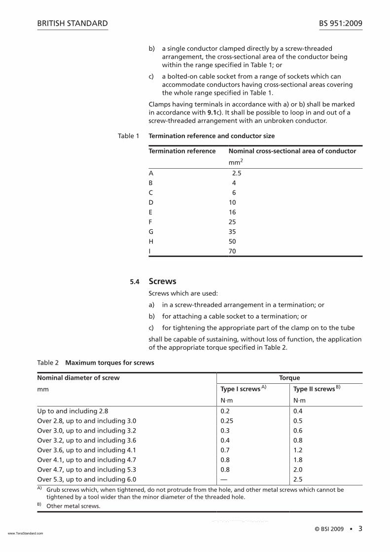
b) a single conductor clamped directly by a screw-threaded arrangement, the cross-sectional area of the conductor being within the range specified in Table 1; or
c) a bolted-on cable socket from a range of sockets which can accommodate conductors having cross-sectional areas covering the whole range specified in Table 1.
Clamps having terminals in accordance with a) or b) shall be marked in accordance with 9.1c). It shall be possible to loop in and out of a screw-threaded arrangement with an unbroken conductor.
Table 1 Termination reference and conductor size
Termination reference Nominal cross-sectional area of conductor
mm2
A 2.5
B 4
C 6
D 10
E 16
F 25
G 35
H 50
I 70
5.4 ScrewsScrews which are used:
a) in a screw-threaded arrangement in a termination; or
b) for attaching a cable socket to a termination; or
c) for tightening the appropriate part of the clamp on to the tube
shall be capable of sustaining, without loss of function, the application of the appropriate torque specified in Table 2.
Table 2 Maximum torques for screws
Nominal diameter of screw
mm
Torque
Type I screws A)
N·m
Type II screws B)
N·m
Up to and including 2.8 0.2 0.4
Over 2.8, up to and including 3.0 0.25 0.5
Over 3.0, up to and including 3.2 0.3 0.6
Over 3.2, up to and including 3.6 0.4 0.8
Over 3.6, up to and including 4.1 0.7 1.2
Over 4.1, up to and including 4.7 0.8 1.8
Over 4.7, up to and including 5.3 0.8 2.0
Over 5.3, up to and including 6.0 — 2.5A) Grub screws which, when tightened, do not protrude from the hole, and other metal screws which cannot be
tightened by a tool wider than the minor diameter of the threaded hole.B) Other metal screws.
www.TeraStandard.com
--```,```,``,`,```````````,,``-`-`,,`,,`,`,,`---

BS 951:2009
4 • © BSI 2009
BRITISH STANDARD
5.5 Warning provisionA permanent label or marking provided with each clamp shall be durably marked in a legible type not less than 2.5 mm high with the words “SAFETY ELECTRICAL CONNECTION — DO NOT REMOVE” in addition to the information specified in 9.1a) and b) where this information is not given on the clamp.
6 MaterialMetal components, including current-carrying parts, shall, according to the intended use (see 9.2), have adequate mechanical strength, resistance to corrosion and, in the case of current-carrying parts, electrical conductivity.
Conformity shall be checked by inspection and, if necessary, by chemical analysis.
The following metals and coatings can be used in normal conditions of chemical pollution.
• Stainless steel containing at least 13% chromium and not more than 0.09% carbon.
• Phosphor bronze.
• Alloy of copper with additional protection, e.g. tin or nickel.
• Steel with a suitable protection, such as:
• an electroplated coating of zinc according to ISO 2081, the coating having a thickness of at least 20 µm;
• an electroplated coating of nickel and chromium according to BS IS0 1456, the coating having a thickness of at least 20 µm;
• an electroplated coating of tin according to ISO 2093, the coating having a thickness of at least 20 µm.
Others coatings with an equivalent degree of protection can be used.
No part shall be made of unalloyed copper.
All parts of the clamp using material less than 1 mm thick shall be inherently resistant to corrosion, e.g. made of phosphor bronze or stainless steel.
7 Electrical characteristics
7.1 Electrical impedance testWhen tested in accordance with Annex A, the impedance between the protective conductor and the tube shall not exceed 0.4 mX.
7.2 Temperature riseWhen tested in accordance with Annex A, the temperature rise measured at the termination of the conductor and the interface of the pipe shall not exceed 52 K.
7.3 Short-time withstand current testWhen tested in accordance with Annex B, no damage that might impair further use shall have occurred to any part of the clamp and
www.TeraStandard.com
--```,```,``,`,```````````,,``-`-`,,`,,`,`,,`---
BRITISH STANDARD
© BSI 2009 • 5
BS 951:2009
the impedance between the protective conductor and the tube shall not exceed 1 mX.
8 Non-slipping torqueWhen a clamp is tested in accordance with Annex C, any movement between the earth clamp band and the test mandrel shall not exceed (2 ±0.5) mm.
9 Marking
9.1 GeneralThe following information shall be clearly and durably marked, either on the clamp or on the warning label provided with it (see Clause 4 and 5.5):
a) the number and date of this British Standard, i.e. BS 951:2009 1);
b) the maker’s name or trademark; and
c) where the clamp has a termination designed to accommodate a range of conductor sizes:
1) the appropriate termination references in accordance with Table 1, with the limits of the range presented in the form “X–Y”, where X is the termination reference of the smallest acceptable conductor and Y is the termination reference of the largest acceptable conductor; or
2) the range of conductor sizes in mm2, e.g. 2.5–6.0.
9.2 Marking of the packageThe package in which the clamp is supplied shall be marked with the following information:
a) the type of application and environment for which it is intended;
b) specific types of tube for which application of the clamp is suitable;
c) the diameter or range of diameters for which the clamp is suitable;
d) where the clamp has a termination designed to accommodate a conductor by a screw-threaded arrangement:
1) the appropriate termination references in accordance with Table 1, with the limits of the range presented in the form “X–Y”, where X is the termination reference of the smallest acceptable conductor and Y is the termination reference of the largest acceptable conductor; or
2) the range of conductor sizes in mm2, e.g. 2.5–6.0;
e) a warning, “Not intended for use on the sheath or armour of a cable”.
1) Marking BS 951:2009 on or in relation to a product represents a manufacturer’s declaration of conformity, i.e. a claim by or on behalf of the manufacturer that the product meets the requirements of the standard. The accuracy of the claim is solely the claimant’s responsibility. Such a declaration is not to be confused with third-party certification of conformity.
www.TeraStandard.com
--```,```,``,`,```````````,,``-`-`,,`,,`,`,,`---
BS 951:2009
6 • © BSI 2009
BRITISH STANDARD
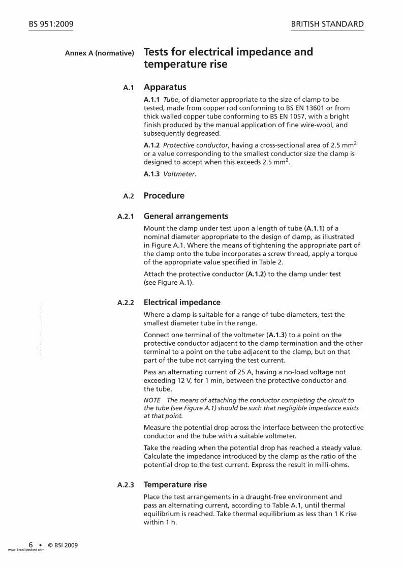
Annex A (normative) Tests for electrical impedance and temperature rise
A.1 ApparatusA.1.1 Tube, of diameter appropriate to the size of clamp to be tested, made from copper rod conforming to BS EN 13601 or from thick walled copper tube conforming to BS EN 1057, with a bright finish produced by the manual application of fine wire-wool, and subsequently degreased.
A.1.2 Protective conductor, having a cross-sectional area of 2.5 mm2 or a value corresponding to the smallest conductor size the clamp is designed to accept when this exceeds 2.5 mm2.
A.1.3 Voltmeter.
A.2 Procedure
A.2.1 General arrangements
Mount the clamp under test upon a length of tube (A.1.1) of a nominal diameter appropriate to the design of clamp, as illustrated in Figure A.1. Where the means of tightening the appropriate part of the clamp onto the tube incorporates a screw thread, apply a torque of the appropriate value specified in Table 2.
Attach the protective conductor (A.1.2) to the clamp under test (see Figure A.1).
A.2.2 Electrical impedance
Where a clamp is suitable for a range of tube diameters, test the smallest diameter tube in the range.
Connect one terminal of the voltmeter (A.1.3) to a point on the protective conductor adjacent to the clamp termination and the other terminal to a point on the tube adjacent to the clamp, but on that part of the tube not carrying the test current.
Pass an alternating current of 25 A, having a no-load voltage not exceeding 12 V, for 1 min, between the protective conductor and the tube.
NOTE The means of attaching the conductor completing the circuit to the tube (see Figure A.1) should be such that negligible impedance exists at that point.
Measure the potential drop across the interface between the protective conductor and the tube with a suitable voltmeter.
Take the reading when the potential drop has reached a steady value. Calculate the impedance introduced by the clamp as the ratio of the potential drop to the test current. Express the result in milli-ohms.
A.2.3 Temperature rise
Place the test arrangements in a draught-free environment and pass an alternating current, according to Table A.1, until thermal equilibrium is reached. Take thermal equilibrium as less than 1 K rise within 1 h.
www.TeraStandard.com
--```,```,``,`,```````````,,``-`-`,,`,,`,`,,`---

BRITISH STANDARD
© BSI 2009 • 7
BS 951:2009
The temperature rise is the difference in temperature between the part under test and the surrounding ambient air temperature. Measure the ambient air temperature during the last quarter of the test period by at least two temperature measurement means equally distributed around the test arrangements at a distance of approximately 1 m from the part under test. Protect the temperature measurement means against air currents and heat radiation.
Measure the temperature rise at the termination of the conductor and the interface of the pipe.
Table A.1 Test currents for temperature rise
Cable cross-sectional area
mm2
Test current
Amps
2.5 30
4 41
6 52
10 72
16 96
25 125
35 155
50 200
70 257
Figure A.1 Test arrangement
www.TeraStandard.com
--```,```,``,`,```````````,,``-`-`,,`,,`,`,,`---

BS 951:2009
8 • © BSI 2009
BRITISH STANDARD
Annex B (normative) Short-time withstand current test
B.1 ApparatusB.1.1 Tube, of diameter appropriate to the size of clamp to be tested, made from copper rod conforming to BS EN 13601 or from thick walled copper tube conforming to BS EN 1057, with a bright finish produced by the manual application of fine wire-wool, and subsequently degreased.
B.1.2 Protective conductor, having a cross-sectional area of 2.5 mm2 or a value corresponding to the greatest conductor size the clamp is designed to accept when this exceeds 2.5 mm2.
B.1.3 Voltmeter.
B.2 Procedure
B.2.1 General arrangements
Mount the clamp under test upon a length of tube (B.1.1) of a nominal diameter appropriate to the design of clamp, as illustrated in Figure B.1. Where the means of tightening the appropriate part of the clamp onto the tube incorporates a screw thread, apply a torque of the appropriate value specified in Table 2.
Attach the protective conductor (B.1.2) to the clamp under test.
B.2.2 Short-time withstand current
Where a clamp is suitable for a range of tube diameters, test the smallest diameter tube in the range.
Carry out the test with the maximum connectable conductor cross-section specified by the manufacturer and the relevant alternating current given in Table B.1.
Connect one terminal of the voltmeter (B.1.3) to a point on the protective conductor adjacent to the clamp termination and the other terminal to a point on the tube adjacent to the clamp but on that part of the tube not carrying the test current.
For time duration of 1 s, pass a value of the current given in Table B.1 in the clamp and the tube.
NOTE The means of attaching the conductor completing the circuit to the tube (see Figure B.1) should be such that negligible impedance exists at that point.
B.2.3 Electrical impedance
After cooling down to ambient temperature, and without any change in the arrangement other than the change of the supply, measure the impedance between the protective conductor and the tube in accordance with the procedure in A.2.2.
www.TeraStandard.com
--```,```,``,`,```````````,,``-`-`,,`,,`,`,,`---
BRITISH STANDARD
© BSI 2009 • 9
BS 951:2009
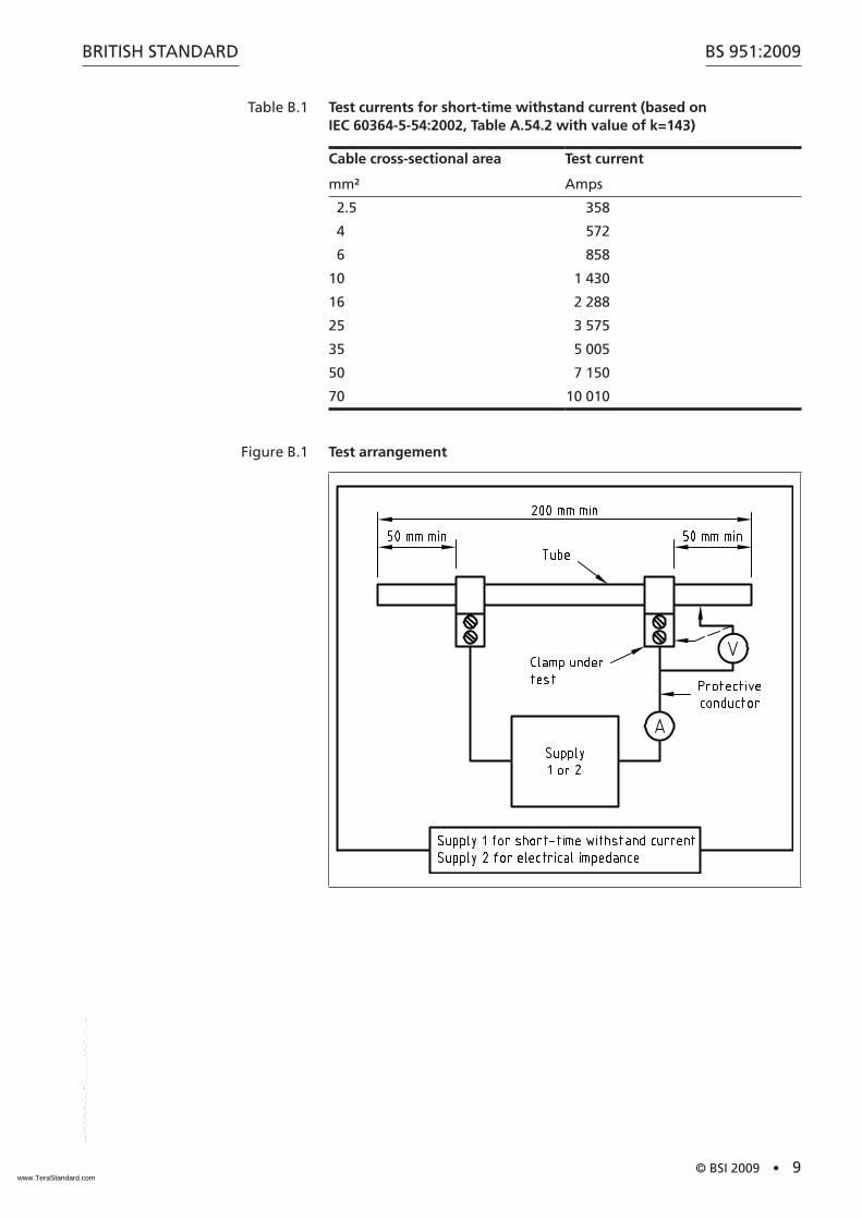
Table B.1 Test currents for short-time withstand current (based on IEC 60364-5-54:2002, Table A.54.2 with value of k=143)
Cable cross-sectional area
mm²
Test current
Amps
2.5 358
4 572
6 858
10 1 430
16 2 288
25 3 575
35 5 005
50 7 150
70 10 010
Figure B.1 Test arrangement
www.TeraStandard.com
--```,```,``,`,```````````,,``-`-`,,`,,`,`,,`---

BS 951:2009
10 • © BSI 2009
BRITISH STANDARD
Annex C (normative) Torque test
C.1 ApparatusC.1.1 Mandrel, of diameter appropriate to the size of clamp to be tested, mounted in a test apparatus as illustrated in Figure C.1, made of low-carbon steel with a smooth machined surface which is then case-hardened.
NOTE Figure C.1 shows the apparatus diagrammatically.
Figure C.1 Apparatus for the torque test
NOTE The details shown of the clamp under test are for the purpose of illustration only.
C.2 ProcedureAttach the clamp to the mandrel (C.1.1). Where the means of tightening incorporates a screw thread, apply a torque not exceeding the appropriate value specified in Table 2. Using a 0.5 mm pencil, mark the earth clamp and mandrel with a fine straight line extending over the width of the clamp under test.
Prevent rotation of the assembly by means of a stop (see Figure C.1) whilst gradually increasing the torque applied to the mandrel up to the value shown in Table C.1.
NOTE A torque spanner is suitable for this purpose.
On reaching the required torque, use a vernier caliper to measure any distortion (movement) of the pencil line between the clamp and the mandrel.
www.TeraStandard.com
--```,```,``,`,```````````,,``-`-`,,`,,`,`,,`---
BRITISH STANDARD
© BSI 2009 • 11
BS 951:2009
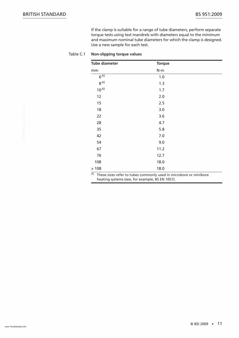
If the clamp is suitable for a range of tube diameters, perform separate torque tests using test mandrels with diameters equal to the minimum and maximum nominal tube diameters for which the clamp is designed. Use a new sample for each test.
Table C.1 Non-slipping torque values
Tube diameter
mm
Torque
N·m
6 A) 1.0
8 A) 1.3
10 A) 1.7
12 2.0
15 2.5
18 3.0
22 3.6
28 4.7
35 5.8
42 7.0
54 9.0
67 11.2
76 12.7
108 18.0
> 108 18.0A) These sizes refer to tubes commonly used in microbore or minibore
heating systems (see, for example, BS EN 1057).
www.TeraStandard.com
--```,```,``,`,```````````,,``-`-`,,`,,`,`,,`---
BS 951:2009
12 • © BSI 2009
BRITISH STANDARD
BibliographyFor dated references, only the edition cited applies. For undated references, the latest edition of the referenced document (including any amendments) applies.
BS EN 60999-1:2000, Connecting devices – Electrical copper conductors – Safety requirements for screw-type and screwless-type clamping units – Part 1: General requirements and particular requirements for clamping units for conductors from 0,2 mm2 up to 35 mm2 (included)
BS ISO 1456, Metallic coatings – Electrodeposited coatings of nickel plus chromium and of copper plus nickel plus chromium
ISO 2081, Metallic coatings – Electroplated coatings of zinc on iron or steel
ISO 2093, Electroplated coatings of tin – Specification and test methods
IEC 60364-5-54:2002, Electrical installations of buildings – Part 5-54: Selection and erection of electrical equipment – Earthing arrangements, protective conductors and protective bonding conductors
www.TeraStandard.com
--```,```,``,`,```````````,,``-`-`,,`,,`,`,,`---

This page deliberately left blankwww.TeraStandard.com
--```,```,``,`,```````````,,``-`-`,,`,,`,`,,`---
BSI is the independent national body responsible for preparing British Standards. It presents the UK view on standards in Europe and at the international level.
It is incorporated by Royal Charter.
British Standards Institution (BSI)
raising standards worldwide™
BSI Group Headquarters
389 Chiswick High Road London W4 4AL UK
Tel +44 (0)20 8996 9001Fax +44 (0)20 8996 7001www.bsigroup.com/standards
RevisionsBritish Standards are updated by amendment or revision. Users of BritishStandards should make sure that they possess the latest amendments oreditions.
It is the constant aim of BSI to improve the quality of our products andservices. We would be grateful if anyone finding an inaccuracy orambiguity while using this British Standard would inform the Secretary ofthe technical committee responsible, the identity of which can be foundon the inside front cover.
Tel: +44 (0)20 8996 9000 Fax: +44 (0)20 8996 7400BSI offers members an individual updating service called PLUS whichensures that subscribers automatically receive the latest editions ofstandards.
Buying standardsOrders for all BSI, international and foreign standards publicationsshould be addressed to BSI Customer Services.
Tel: +44 (0)20 8996 9001 Fax: +44 (0)20 8996 7001Email: [email protected] may also buy directly using a debit/credit card from the BSI Shopon the website www.bsigroup.com/shopIn response to orders for international standards, it is BSI policy tosupply the BSI implementation of those that have been publishedas British Standards, unless otherwise requested.
Information on standardsBSI provides a wide range of information on national, European andinternational standards through its Library.
Various BSI electronic information services are also available which givedetails on all its products and services. Contact the Information Centre.
Tel: +44 (0)20 8996 7111 Fax: +44 (0)20 8996 7048 Email: [email protected] members of BSI are kept up to date with standardsdevelopments and receive substantial discounts on the purchase priceof standards. For details of these and other benefits contact MembershipAdministration.
Tel: +44 (0)20 8996 7002 Fax: +44 (0)20 8996 7001 Email: [email protected] Information regarding online access to British Standards via BritishStandards Online can be found at www.bsigroup.com/BSOLFurther information about BSI is available on the BSI website atwww.bsigroup.com
CopyrightCopyright subsists in all BSI publications. BSI also holds the copyright, in the UK, of thepublications of the international standardization bodies. Except as permitted under theCopyright, Designs and Patents Act 1988 no extract may be reproduced, stored in a retrievalsystem or transmitted in any form or by any means – electronic, photocopying, recording orotherwise – without prior written permission from BSI. This does not preclude the free use, in the course of implementing the standard of necessarydetails such as symbols, and size, type or grade designations. If these details are to be used forany other purpose than implementation then the prior written permission of BSI must beobtained. Details and advice can be obtained from the Copyright & Licensing Manager.
Tel: +44 (0)20 8996 7070 Email: [email protected]
WB9423_BSI_StandardColCov_noK_AW:BSI FRONT COVERS 5/9/08 12:55 Page 2
www.TeraStandard.com
--```,```,``,`,```````````,,``-`-`,,`,,`,`,,`---


![[BSI] BS 25999-1 Code of Practice for Business Continuity Management](https://static.fdocuments.us/doc/165x107/5475da50b4af9fb40a8b5e97/bsi-bs-25999-1-code-of-practice-for-business-continuity-management.jpg)


