B.Satyanarayana Department of High Energy Physics Tata Institute of Fundamental Research Homi Bhabha...
23
B.Satyanarayana Department of High Energy Physics Tata Institute of Fundamental Research Homi Bhabha Road, Colaba, Mumbai, 400 005 E-mail: [email protected] Electronics, trigger and DAQ system for INO prototype detector and A few thoughts for ICAL detector
-
Upload
nathan-griffin-clark -
Category
Documents
-
view
216 -
download
0
Transcript of B.Satyanarayana Department of High Energy Physics Tata Institute of Fundamental Research Homi Bhabha...

B.Satyanarayana
Department of High Energy PhysicsTata Institute of Fundamental Research
Homi Bhabha Road, Colaba, Mumbai, 400 005E-mail: [email protected]
Electronics, trigger and DAQ system for INO prototype detector
andA few thoughts for ICAL detector

B.Satyanarayana IMSc, Chennai February 22-24, 2006 2
INO prototype detector• Detector and signal specifications
– Detector dimensions: 1m X 1m X 1m (approx.)– 14 layers (max) of RPCs with 6cm iron plates interleaved.– Two signal planes orthogonal to each other and each having 32 pick-up strips– Total channels = 32 X 14 X 2 = 896– Pulse height = 100 to 300mV; Rise time = < 1 ns– Pulse width = ~50ns; Rate ~ 1KHz
• Trigger information
– Expected trigger rate is few Hz– Required (in situ) trigger logic is m X n fold, where – m = 1 to 4; no. of consecutive channels in a layer – n = 5 to 1; no. of consecutive layers with m fold in each layer – i.e. m x n = (1 x 5) OR (2 x 4) OR (3 x 3) OR (4 x 2)– External scintillate paddle based trigger
• Information to be recorded on a trigger – Absolute arrival time of the trigger – Track identification (XYZ points in RPC layers)– Direction of track ( TDC information)– Miscellaneous information and calibration data
• Monitoring health of the detector

B.Satyanarayana IMSc, Chennai February 22-24, 2006 3
Readout scheme for prototype X-plane RTC Y Final X Trigger TDCs Event scalers
FEE Control module Data readout
module Monitor data scalers Ethernet Controller
PC (LINUX)
CAMAC
1 2 8 9 10 14
1 2 8 9 10 14
Front End Electronics
Trig & TDC Router
Y-p
lane

B.Satyanarayana IMSc, Chennai February 22-24, 2006 4
Fast preamplifier• Provided by Electronic Division, BARC• Currently being used with avalanche mode
operation• Fixed gain (10), single channel, single polarity,
with discrete components (availability issues)

B.Satyanarayana IMSc, Chennai February 22-24, 2006 5
Preamp hybrid• Bipolar operation tested• To be packaged into a hybrid (BEL)• Possible to mount on the RPC pickup strips• Will improve signal to noise• Fabrication procedure
– Circuit schematic by BARC– Layout preparation by BEL (2-3 weeks)– Pilot production by BEL and validation (1 month)– Final production (4-6 weeks)– Problem: Purchase procedural delays (File with IFA)

B.Satyanarayana IMSc, Chennai February 22-24, 2006 6
16-channel analog front-end• Based on Analog Devices’ Quad-device
• Fast comparator with ECL outputs
• Wire ORed pre-trigger outputs
• Production board tested with RPC strip signals
• Works as good as commercial units
• Components being procured
• Ready for production (2-3 months)
• Partial production boards arrived

B.Satyanarayana IMSc, Chennai February 22-24, 2006 7
32-channel digital front-end 1 2 3 ……………………………………………………………32
Threshold
Mon SI
Mon SO
Addr & Control
Event Trig
Eve SI Eve
SO
CPLD
32 ECL Comparators
Trigger 0 Logic (ECL)
&
Timing signal
Trigger 1 M fold Logic
( CPLD )
Level Translator & Wave shaper (32+8)
SHIFT REGISTER ( 48 bit )
Board ID (SW8)
Monitor
MUX unit ( 40 : 1 )
Module Selection
LV
DS
EVE (SW4) MON(SW4)
Counter

B.Satyanarayana IMSc, Chennai February 22-24, 2006 8
Digital front-end status• Logic fused into a CPLD XC 95288 -HQ708
• Code tested on a simulator and hardware using a pattern generator
• Jig fabricated to test the logic on RPC signals
• Work in progress (2 weeks); delayed due to manpower redeployment; restarted now
• PCB layout is also in progress
• Production estimate about 3 months

B.Satyanarayana IMSc, Chennai February 22-24, 2006 9
Prototype detector trigger logic
Front End Electronics X-Plane Y-Plane Level-0
Level 1 S1….S8 S1…S8 S1…S8
1F,2F……4F 1F,2F……4F 1F,2F……4F 1F,2F……4F (LVDS interface)
Level-2 ( Back end )
F1(14)…………..F4(14) F1(14)…………..F4(14) (
OR
L1P1
(mF)
L14P1
(mF) L14P2
(mF) L1P2
(mF)
P1 (m x n fold)
P2 (m x n fold)
Final Trigger
S1=1+9+17+25 S2=2+10+18+26 ………. S8=8+16+24+32
Trigger & TDC signals Router
Trigger & TDC signals Router
B.Satyanarayana IMSc, Chennai February 22-24, 2006 10
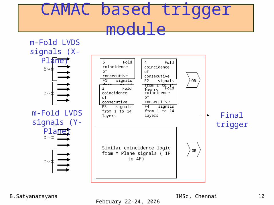
CAMAC based trigger moduleF
R C
60
FR C
60
FR C
60
FR C
60
5 Fold coincidence of consecutive F1 signals from 1 to 14 layers
2 Fold coincidence of consecutive F4 signals from 1 to 14 layers
3 Fold coincidence of consecutive F3 signals from 1 to 14 layers
4 Fold coincidence of consecutive F2 signals from 1 to 14 layers
OR
Similar coincidence logic from Y Plane signals ( 1F to 4F)
OR
Final trigger
m-Fold LVDS signals (X-Plane)
m-Fold LVDS signals (Y-Plane)

B.Satyanarayana IMSc, Chennai February 22-24, 2006 11
Trigger module status• Being developed by Electronics Division, BARC
• Implemented using a FPGA
• Major part of logic coded; scalars to be done
• Module given for fabrication; now delivered
• Expected to be ready in two months
• Testing and debugging (1 month)

B.Satyanarayana IMSc, Chennai February 22-24, 2006 12
CAMAC based control module
Generates three sets of control and hand shake signals for selection of DFE board, readout of event data and monitoring of pickup signals in the selected board

B.Satyanarayana IMSc, Chennai February 22-24, 2006 13
CAMAC based readout module• Four serial event data read out channels• Eight monitor data inputs• Serial to parallel conversion of event data• Data written into FIFO buffer• FIFO buffers readout through CAMAC backplane in the
event routine• Eight selected monitor channels translated into ECL logic
signals• Rates monitored through ECL input CAMAC scalar
modules• Module is ready

B.Satyanarayana IMSc, Chennai February 22-24, 2006 14
Other items• High voltage supplies (CAEN, SINP)
• Low voltage supplies (Local)
• Components, cables etc
• Commercial/available modules– TDCs– Scalers– CAMAC crates and controllers
• DAQ software on Linux platform– Technical specification ready

B.Satyanarayana IMSc, Chennai February 22-24, 2006 15
Thoughts on eTRIDAS for ICAL
• KGF still inspires!
• Channel count a factor of 1000 for ICAL
• Time tested ideas; blended with VLSI technology
• Reasonably simple scheme; the need is density
• Low rates; high degree of multiplexing possible
• ASICs, pipelining, trigger farm,VME are the keys
• ASICs for front-end, timing, even for trigger!

B.Satyanarayana IMSc, Chennai February 22-24, 2006 16
Major sub-systems• Analog and digital front-ends
– Mounted on or very close to detectors
– Programmable preamps and comparators
– Latches, pre-trigger generators, pipelines and buffers
– Data concentrators and high speed serial transmitters
• VME back-ends– Data collectors and frame transmitters
– Time to digital converters (TDCs)
• Trigger system– Works on inputs from front-ends, back-ends or external
– Place for high density FPGA devices

B.Satyanarayana IMSc, Chennai February 22-24, 2006 17
DAQ scheme for final detectorThe keywords are channel count and fast timing

B.Satyanarayana IMSc, Chennai February 22-24, 2006 18
Readout system concept

B.Satyanarayana IMSc, Chennai February 22-24, 2006 19
Front-end ASIC concept

B.Satyanarayana IMSc, Chennai February 22-24, 2006 20
Slow control and Monitoring• Front-end control and monitoring• High voltage control and monitoring of V & I• Gas system monitoring
– Channel control and flow monitoring– On-line gas sample analysis (RGA)– Gas leak monitoring– Moister level monitoring
• Ambient parameter monitoring– Temperature, barometric pressure, relative humidity– Data can be used for even for off-line corrections

B.Satyanarayana IMSc, Chennai February 22-24, 2006 21
High voltage system• Number of independently controllable channels?
– 3 detector modules, 140 layers, 16m X 16m lateral size and RPC area of 2m X 2m
• Worst case: Combine all RPCs in a layer 420 channels• Best case: One channel per RPC 27,000 channels!• We can settle for one channel/road/layer, for example
• Ramp rate, channel control, voltage and current monitoring are the bare minimum requirements
• Modular structure, Ethernet interface, local consoles, distributed displays, complete high voltage discharge etc are most desired features

B.Satyanarayana IMSc, Chennai February 22-24, 2006 22
Some technology standards• Backend: VME
• Platform: Linux?
• Networking of processing nodes
• Front-end, gas system and HV control: Ethernet
• Ambient parameter monitoring: Embedded processors with Ethernet interfaces
• Web servers for operating parameter browsers
• On-fly sample data quality checks

B.Satyanarayana IMSc, Chennai February 22-24, 2006 23
Preliminary action plan• Expertise from TIFR, BARC, SINP, VECC,
IITB, IGCAR, NSC etc (Proposal from BHU)
• Industry ready and active
• ASIC design process must begin now
• Comparator ASIC work by SINP; BARC waiting
• Tools and training of personnel
• Updating of experiment’s requirements of eTRIDAS
• Discussion meeting at national level