
bs41mt
222
Maintenance Base Transceiver Station Equipment MMN:BTSE BS-41 A30808-X3247-M281-1-7620
-
Upload
sinasabikona -
Category
Documents
-
view
1 -
download
0
description
siemens bs41 mt
Transcript of bs41mt

Maintenance
Base Transceiver Station Equipment
MMN:BTSE BS-41
A30808-X3247-M281-1-7620

MaintenanceBase Transceiver Station Equipment
2 A30808-X3247-M281-1-7620
MMN:BTSE BS-41
f Important Notice on Product Safety
DANGER - RISK OF ELECTRICAL SHOCK OR DEATH - FOLLOW ALL INSTALLATION INSTRUCTIONS.
The system complies with the standard EN 60950 / IEC 60950. All equipment connected to the system mustcomply with the applicable safety standards.Hazardous voltages are present at the AC power supply lines in this electrical equipment. Some components mayalso have high operating temperatures.Failure to observe and follow all installation and safety instructions can result in serious personal injuryor property damage.Therefore, only trained and qualified personnel may install and maintain the system.
The same text in German:
Wichtiger Hinweis zur Produktsicherheit
LEBENSGEFAHR - BEACHTEN SIE ALLE INSTALLATIONSHINWEISE.
Das System entspricht den Anforderungen der EN 60950 / IEC 60950. Alle an das System angeschlossenenGeräte müssen die zutreffenden Sicherheitsbestimmungen erfüllen.In diesen Anlagen stehen die Netzversorgungsleitungen unter gefährlicher Spannung. Einige Komponentenkönnen auch eine hohe Betriebstemperatur aufweisen.Nichtbeachtung der Installations- und Sicherheitshinweise kann zu schweren Körperverletzungen oderSachschäden führen.Deshalb darf nur geschultes und qualifiziertes Personal das System installieren und warten.
Caution:This equipment has been tested and found to comply with EN 301489. Its class of conformity is defined in tableA30808-X3247-X910-*-7618, which is shipped with each product. This class also corresponds to the limits for aClass A digital device, pursuant to part 15 of the FCC Rules.These limits are designed to provide reasonable protection against harmful interference when the equipment isoperated in a commercial environment.This equipment generates, uses and can radiate radio frequency energy and, if not installed and used in accor-dance with the relevant standards referenced in the manual “Guide to Documentation”, may cause harmful inter-ference to radio communications.For system installations it is strictly required to choose all installation sites according to national and local require-ments concerning construction rules and static load capacities of buildings and roofs.For all sites, in particular in residential areas it is mandatory to observe all respectively applicable electromagneticfield / force (EMF) limits. Otherwise harmful personal interference is possible.
Trademarks:
All designations used in this document can be trademarks, the use of which by third parties for their own purposescould violate the rights of their owners.
Copyright (C) Siemens AG 2005.
Issued by the Communications GroupHofmannstraße 51D-81359 München
Technical modifications possible.Technical specifications and features are binding only insofar asthey are specifically and expressly agreed upon in a written contract.

A30808-X3247-M281-1-7620 3
MaintenanceBase Transceiver Station Equipment
MMN:BTSE BS-41
Reason for UpdateSummary:
First Edition for New Release BR 8.0
Details:
Chapter/Section Reason for Update
all New Release BR 8.0
Issue HistoryIssue
Number
Date of Issue Reason for Update
1 01/2005 First Edition for New Release BR 8.0

4 A30808-X3247-M281-1-7620
MMN:BTSE BS-41 MaintenanceBase Transceiver Station Equipment

A30808-X3247-M281-1-7620 5
MaintenanceBase Transceiver Station Equipment
MMN:BTSE BS-41
This document consists of a total of 222 pages. All pages are issue 1.
Contents
1 Introduction . . . . . . . . . . . . . . . . . . . . . . . . . . . . . . . . . . . . . . . . . . . . . . . . . . 91.1 Structure of the Maintenance Manual . . . . . . . . . . . . . . . . . . . . . . . . . . . . . . 91.2 Symbols Used. . . . . . . . . . . . . . . . . . . . . . . . . . . . . . . . . . . . . . . . . . . . . . . 101.3 Fault Clearance Principle . . . . . . . . . . . . . . . . . . . . . . . . . . . . . . . . . . . . . . 111.4 Fault Clearance Guidelines. . . . . . . . . . . . . . . . . . . . . . . . . . . . . . . . . . . . . 121.5 Module Replacement Instructions. . . . . . . . . . . . . . . . . . . . . . . . . . . . . . . . 141.5.1 ESD Precautions. . . . . . . . . . . . . . . . . . . . . . . . . . . . . . . . . . . . . . . . . . . . . 141.5.2 Avoiding the Loss of Calls. . . . . . . . . . . . . . . . . . . . . . . . . . . . . . . . . . . . . . 141.5.3 Removing and Inserting Modules . . . . . . . . . . . . . . . . . . . . . . . . . . . . . . . . 161.5.4 Quick Module Replacement . . . . . . . . . . . . . . . . . . . . . . . . . . . . . . . . . . . . 181.6 Closing the Shelter Door. . . . . . . . . . . . . . . . . . . . . . . . . . . . . . . . . . . . . . . 19
2 Tasklist . . . . . . . . . . . . . . . . . . . . . . . . . . . . . . . . . . . . . . . . . . . . . . . . . . . . 21
3 Fault Clearance Procedures for Modules and Interfaces . . . . . . . . . . . . . . 233.1 Abis . . . . . . . . . . . . . . . . . . . . . . . . . . . . . . . . . . . . . . . . . . . . . . . . . . . . . . . 243.2 ABISCON . . . . . . . . . . . . . . . . . . . . . . . . . . . . . . . . . . . . . . . . . . . . . . . . . . 273.3 AC/DC. . . . . . . . . . . . . . . . . . . . . . . . . . . . . . . . . . . . . . . . . . . . . . . . . . . . . 283.4 ACDCP . . . . . . . . . . . . . . . . . . . . . . . . . . . . . . . . . . . . . . . . . . . . . . . . . . . . 323.5 ACT. . . . . . . . . . . . . . . . . . . . . . . . . . . . . . . . . . . . . . . . . . . . . . . . . . . . . . . 333.6 Battery. . . . . . . . . . . . . . . . . . . . . . . . . . . . . . . . . . . . . . . . . . . . . . . . . . . . . 383.7 BPORT . . . . . . . . . . . . . . . . . . . . . . . . . . . . . . . . . . . . . . . . . . . . . . . . . . . . 423.8 COBA Without CORE Redundancy . . . . . . . . . . . . . . . . . . . . . . . . . . . . . . 433.9 COBA With CORE Redundancy . . . . . . . . . . . . . . . . . . . . . . . . . . . . . . . . . 533.10 COBA2P8 - COBA4P12 Without CORE Redundancy . . . . . . . . . . . . . . . . 633.11 COBA2P8 - COBA4P12 With CORE Redundancy. . . . . . . . . . . . . . . . . . . 733.12 COREXT . . . . . . . . . . . . . . . . . . . . . . . . . . . . . . . . . . . . . . . . . . . . . . . . . . . 833.13 COSA . . . . . . . . . . . . . . . . . . . . . . . . . . . . . . . . . . . . . . . . . . . . . . . . . . . . . 873.14 CU. . . . . . . . . . . . . . . . . . . . . . . . . . . . . . . . . . . . . . . . . . . . . . . . . . . . . . . . 943.15 DCBCTRL . . . . . . . . . . . . . . . . . . . . . . . . . . . . . . . . . . . . . . . . . . . . . . . . . 1003.16 DIAMCO . . . . . . . . . . . . . . . . . . . . . . . . . . . . . . . . . . . . . . . . . . . . . . . . . . 1043.17 DIDCTMA . . . . . . . . . . . . . . . . . . . . . . . . . . . . . . . . . . . . . . . . . . . . . . . . . 1113.18 DILNA . . . . . . . . . . . . . . . . . . . . . . . . . . . . . . . . . . . . . . . . . . . . . . . . . . . . 1123.19 DIPLEXER . . . . . . . . . . . . . . . . . . . . . . . . . . . . . . . . . . . . . . . . . . . . . . . . 1133.20 DUAMCO . . . . . . . . . . . . . . . . . . . . . . . . . . . . . . . . . . . . . . . . . . . . . . . . . 1203.21 DUBIAS. . . . . . . . . . . . . . . . . . . . . . . . . . . . . . . . . . . . . . . . . . . . . . . . . . . 1273.22 DUDCTMA . . . . . . . . . . . . . . . . . . . . . . . . . . . . . . . . . . . . . . . . . . . . . . . . 1333.23 DULNA . . . . . . . . . . . . . . . . . . . . . . . . . . . . . . . . . . . . . . . . . . . . . . . . . . . 1343.24 ECU . . . . . . . . . . . . . . . . . . . . . . . . . . . . . . . . . . . . . . . . . . . . . . . . . . . . . 1353.25 FAN. . . . . . . . . . . . . . . . . . . . . . . . . . . . . . . . . . . . . . . . . . . . . . . . . . . . . . 1363.26 FDUAMCO . . . . . . . . . . . . . . . . . . . . . . . . . . . . . . . . . . . . . . . . . . . . . . . . 1403.27 FICOM . . . . . . . . . . . . . . . . . . . . . . . . . . . . . . . . . . . . . . . . . . . . . . . . . . . 1413.28 FTNFP . . . . . . . . . . . . . . . . . . . . . . . . . . . . . . . . . . . . . . . . . . . . . . . . . . . 1493.29 FVSWRP. . . . . . . . . . . . . . . . . . . . . . . . . . . . . . . . . . . . . . . . . . . . . . . . . . 1503.30 GCU . . . . . . . . . . . . . . . . . . . . . . . . . . . . . . . . . . . . . . . . . . . . . . . . . . . . . 151
6 A30808-X3247-M281-1-7620
MMN:BTSE BS-41 MaintenanceBase Transceiver Station Equipment
3.31 Heater . . . . . . . . . . . . . . . . . . . . . . . . . . . . . . . . . . . . . . . . . . . . . . . . . . . . 1523.32 HEX . . . . . . . . . . . . . . . . . . . . . . . . . . . . . . . . . . . . . . . . . . . . . . . . . . . . . . 1533.33 HPDU. . . . . . . . . . . . . . . . . . . . . . . . . . . . . . . . . . . . . . . . . . . . . . . . . . . . . 1553.34 LAPDLE . . . . . . . . . . . . . . . . . . . . . . . . . . . . . . . . . . . . . . . . . . . . . . . . . . . 1613.35 MEF . . . . . . . . . . . . . . . . . . . . . . . . . . . . . . . . . . . . . . . . . . . . . . . . . . . . . . 1623.36 OVPT . . . . . . . . . . . . . . . . . . . . . . . . . . . . . . . . . . . . . . . . . . . . . . . . . . . . . 1633.37 PCM Line . . . . . . . . . . . . . . . . . . . . . . . . . . . . . . . . . . . . . . . . . . . . . . . . . . 1713.38 Rectifier . . . . . . . . . . . . . . . . . . . . . . . . . . . . . . . . . . . . . . . . . . . . . . . . . . . 1733.39 Remote Inventory Data Update . . . . . . . . . . . . . . . . . . . . . . . . . . . . . . . . . 1743.40 TMA . . . . . . . . . . . . . . . . . . . . . . . . . . . . . . . . . . . . . . . . . . . . . . . . . . . . . . 1783.41 TX/RX Path (e.g. VSWR) . . . . . . . . . . . . . . . . . . . . . . . . . . . . . . . . . . . . . . 184
4 Tables, Lists and Figures . . . . . . . . . . . . . . . . . . . . . . . . . . . . . . . . . . . . . . 1874.1 Hardware Architecture . . . . . . . . . . . . . . . . . . . . . . . . . . . . . . . . . . . . . . . . 1894.2 Detailed Information on Hardware Components (Modules, Frames and Racks)
1914.3 Front View of the BS-41 Shelter. . . . . . . . . . . . . . . . . . . . . . . . . . . . . . . . . 1924.4 Corresponding Hardware Managed Objects (HMO) . . . . . . . . . . . . . . . . . 1954.5 TX/RX Paths of Some Configuration Examples. . . . . . . . . . . . . . . . . . . . . 196
5 Appendix . . . . . . . . . . . . . . . . . . . . . . . . . . . . . . . . . . . . . . . . . . . . . . . . . . 2055.1 HW/SW Compatibility During Download from LMT/BSC . . . . . . . . . . . . . . 2055.2 State/Status Attributes of BTSE Managed Objects . . . . . . . . . . . . . . . . . . 2065.3 BTSE Alarm Information . . . . . . . . . . . . . . . . . . . . . . . . . . . . . . . . . . . . . . 2085.3.1 Probable Cause Value . . . . . . . . . . . . . . . . . . . . . . . . . . . . . . . . . . . . . . . . 2085.3.2 Event Types . . . . . . . . . . . . . . . . . . . . . . . . . . . . . . . . . . . . . . . . . . . . . . . . 2085.3.3 Perceived Severity . . . . . . . . . . . . . . . . . . . . . . . . . . . . . . . . . . . . . . . . . . . 2095.3.4 Trend Indication . . . . . . . . . . . . . . . . . . . . . . . . . . . . . . . . . . . . . . . . . . . . . 2095.3.5 Immediate Defense Action . . . . . . . . . . . . . . . . . . . . . . . . . . . . . . . . . . . . . 2095.3.6 Threshold Information . . . . . . . . . . . . . . . . . . . . . . . . . . . . . . . . . . . . . . . . 2105.3.7 Proposed Repair Action . . . . . . . . . . . . . . . . . . . . . . . . . . . . . . . . . . . . . . . 2105.3.8 Error Description . . . . . . . . . . . . . . . . . . . . . . . . . . . . . . . . . . . . . . . . . . . . 2105.3.9 Additional Information . . . . . . . . . . . . . . . . . . . . . . . . . . . . . . . . . . . . . . . . 2105.4 Fault Messages . . . . . . . . . . . . . . . . . . . . . . . . . . . . . . . . . . . . . . . . . . . . . 2105.4.1 Fault Messages at the Radio Commander. . . . . . . . . . . . . . . . . . . . . . . . . 2105.4.2 Fault Messages at the LMT . . . . . . . . . . . . . . . . . . . . . . . . . . . . . . . . . . . . 2115.5 BTSE Components . . . . . . . . . . . . . . . . . . . . . . . . . . . . . . . . . . . . . . . . . . 2115.5.1 BTSE Components Overview . . . . . . . . . . . . . . . . . . . . . . . . . . . . . . . . . . 2115.5.2 Numbering of BTSE Components . . . . . . . . . . . . . . . . . . . . . . . . . . . . . . . 2115.5.3 Remote Inventory Data . . . . . . . . . . . . . . . . . . . . . . . . . . . . . . . . . . . . . . . 2125.6 Diagnostics / Test. . . . . . . . . . . . . . . . . . . . . . . . . . . . . . . . . . . . . . . . . . . . 2145.6.1 General . . . . . . . . . . . . . . . . . . . . . . . . . . . . . . . . . . . . . . . . . . . . . . . . . . . 2145.6.2 Requirements for Starting the BTSE Module Test . . . . . . . . . . . . . . . . . . . 214
6 Abbreviations . . . . . . . . . . . . . . . . . . . . . . . . . . . . . . . . . . . . . . . . . . . . . . . 219
7 Index . . . . . . . . . . . . . . . . . . . . . . . . . . . . . . . . . . . . . . . . . . . . . . . . . . . . . 221

A30808-X3247-M281-1-7620 7
MaintenanceBase Transceiver Station Equipment
MMN:BTSE BS-41
IllustrationsFig. 1.1 Structure of the MMN:BTSE . . . . . . . . . . . . . . . . . . . . . . . . . . . . . . . . . . 9
Fig. 1.2 Used Symbols . . . . . . . . . . . . . . . . . . . . . . . . . . . . . . . . . . . . . . . . . . . . 10
Fig. 1.3 Fault Clearance Overview . . . . . . . . . . . . . . . . . . . . . . . . . . . . . . . . . . . 12
Fig. 1.4 ESD Symbol. . . . . . . . . . . . . . . . . . . . . . . . . . . . . . . . . . . . . . . . . . . . . . 14
Fig. 1.5 Module Fastening Variants . . . . . . . . . . . . . . . . . . . . . . . . . . . . . . . . . . 16
Fig. 1.6 Location of the Plug-in Module Code Keys . . . . . . . . . . . . . . . . . . . . . . 17
Fig. 1.7 Location of the Code Key Number. . . . . . . . . . . . . . . . . . . . . . . . . . . . . 17
Fig. 1.8 Closing the Shelter Door: Handle Positions. . . . . . . . . . . . . . . . . . . . . . 19
Fig. 3.1 Editing Nob_RIU Units . . . . . . . . . . . . . . . . . . . . . . . . . . . . . . . . . . . . . 175
Fig. 4.1 BS-41. . . . . . . . . . . . . . . . . . . . . . . . . . . . . . . . . . . . . . . . . . . . . . . . . . 189
Fig. 4.2 Functional blocks . . . . . . . . . . . . . . . . . . . . . . . . . . . . . . . . . . . . . . . . . 190
Fig. 4.3 Functional Blocks of BS-240XL Base Rack with COBA4P12 and COREXTModules . . . . . . . . . . . . . . . . . . . . . . . . . . . . . . . . . . . . . . . . . . . . . . . . 191
Fig. 4.4 BS-41 Base Shelter Design and Configuration . . . . . . . . . . . . . . . . . . 192
Fig. 4.5 BS-41 Service2 Shelter Design and Configuration (example) . . . . . . . 193
Fig. 4.6 4 Carrier BTSE BS-41 . . . . . . . . . . . . . . . . . . . . . . . . . . . . . . . . . . . . . 194
Fig. 4.7 TX/RX Paths of Configuration with FICOM, DIAMCO, HPDU, DUBIAS,TMA . . . . . . . . . . . . . . . . . . . . . . . . . . . . . . . . . . . . . . . . . . . . . . . . . . . 198
Fig. 4.8 TX/RX Paths of Configuration with DUAMCO / FDUAMCO . . . . . . . . 201
Fig. 4.9 TX/RX Paths of Configuration with DIPLEXER . . . . . . . . . . . . . . . . . . 203
Fig. 5.1 Fault Messages at the Radio Commander . . . . . . . . . . . . . . . . . . . . . 210

8 A30808-X3247-M281-1-7620
MMN:BTSE BS-41 MaintenanceBase Transceiver Station Equipment
TablesTab. 4.1 Possible Modules and their Hardware Managed Objects (HMO) for FlexCU
195
Tab. 4.2 Possible Modules and their Hardware Managed Objects (HMO) for ACOM195
Tab. 4.3 Possible Modules and their Hardware Managed Objects (HMO) for MUCO196
Tab. 4.4 Possible Modules and their Hardware Managed Objects (HMO) forDCBCTRL . . . . . . . . . . . . . . . . . . . . . . . . . . . . . . . . . . . . . . . . . . . . . . . 196
Tab. 4.5 Failure Causes in the TX/RX Path, Configuration with FICOM, DIAMCO,HPDU, DUBIAS, TMA. . . . . . . . . . . . . . . . . . . . . . . . . . . . . . . . . . . . . . 199
Tab. 4.6 Failure Causes in the TX/RX Path, Configuration with DUAMCO / FDUAM-CO. . . . . . . . . . . . . . . . . . . . . . . . . . . . . . . . . . . . . . . . . . . . . . . . . . . . . 202
Tab. 4.7 Failure Causes in the TX/RX Path, Configuration with DUAMCO / FDUAM-CO, FICOM, DIPLEXER . . . . . . . . . . . . . . . . . . . . . . . . . . . . . . . . . . . . 204
Tab. 5.1 State/Status Attributes of BTSE MOs . . . . . . . . . . . . . . . . . . . . . . . . . . 206
Tab. 5.2 Shelter Numbering . . . . . . . . . . . . . . . . . . . . . . . . . . . . . . . . . . . . . . . . 212
Tab. 5.3 List of nob_RIUs . . . . . . . . . . . . . . . . . . . . . . . . . . . . . . . . . . . . . . . . . . 213

A30808-X3247-M281-1-7620 9
MaintenanceBase Transceiver Station Equipment
MMN:BTSE BS-41
1 Introduction
1.1 Structure of the Maintenance Manual
The following diagram gives an overview of the structure of this manual and the purposeof its chapters.
Fig. 1.1 Structure of the MMN:BTSE
Chapter 1
Chapter 2
Chapter 3
Chapter 5
Introduction– Basic information on this manual– Basic information on fault clearance– Guidelines– General replacement Instructions– Preparatory work if relevant
Chapter 6 Abbreviations
AppendixBasic required knowledge in more detail,e.g. fault messages
Chapter 4
Fault Clearance Procedures for Modulesand Interfaces– Fault clearance procedures for modules,
interfaces and MOs in alphabetical order– Concluding procedure “Remote Inventory
Data Update” that some fault clearanceprocedures require (if necessary, links areprovided to this concluding procedure)
Tables, Lists and Figures– Overview of the HW architecture as
additional information
(Important information to make your workefficient and safe)
(Main Part for Fault Clearance Tasks)
(Reference Chapter)
(Reference Chapter)
(General Maintenance)
(Reference Chapter)
Chapter 7 Index (Reference Chapter)
Task ListInformation on routine tasks that need to becarried out

10 A30808-X3247-M281-1-7620
MMN:BTSE BS-41 MaintenanceBase Transceiver Station Equipment
1.2 Symbols Used
The following symbols are used throughout this manual:
Fig. 1.2 Used Symbols
Reference to another procedure step
Symbol Meaning
ESD (Electrostatic Sensitive Device) precautions to be taken
Note; important information
Warning; the notes given here are to be followed with care.
b
h
Use LMT to enter commands
Reference to another chapter
Reference to another procedure. Return after finishing.i
i
!Non-observance can lead to personal injury or property damage.

A30808-X3247-M281-1-7620 11
MaintenanceBase Transceiver Station Equipment
MMN:BTSE BS-41
1.3 Fault Clearance Principle
The high system functionality of the Siemens Base Station System is achieved bymeans of system-integrated routine tests. These routine tests continually check the cor-rect functioning of the base station subsystems including the BTSEs.
The fault clearance procedures in this manual are based on these routine tests. In mostcases, the results of these routine tests are sufficient to localize the fault and clear it im-mediately at the BTSE.
The modular design of the BTSE allows you to clear a large percentage of faults in thesystem by replacing a defective module.
Sometimes, however, it may happen that faults do not result from defective modules,but from interface problems in general (for example interrupted cables). In this case,special trouble shooting procedures for interfaces are provided.
This maintenance concept guarantees a simple and fast fault clearance and leads tohigh operational efficiency.

12 A30808-X3247-M281-1-7620
MMN:BTSE BS-41 MaintenanceBase Transceiver Station Equipment
1.4 Fault Clearance Guidelines
The following diagram gives an overview of the fault clearance procedure (detailed de-scription below):
Fig. 1.3 Fault Clearance Overview
7.
Y
Y
6.AnotherProbableCause?
9. End of Fault Clearance: Faulty Modules are Sent to Repair Depot
Fault and Test Man-agement at theOMC via Radio
Commander
N
1. System Integrated Routine Test Detects a Fault
3.Local Fault
Clearance at theBTSE Neces-
sary?
YN
2. Fault Message Displayed at Radio Commander:Information for example on– probable cause– suspected modules(s)/interface(s)– location ...
Local FaultClearance at
the BTSE
4. Fault Clearance Proce-dure for the Suspected
Module or Interface
8. CallTAC
5.Fault
ClearanceSuccess-
ful?
Content of this Manual
N

A30808-X3247-M281-1-7620 13
MaintenanceBase Transceiver Station Equipment
MMN:BTSE BS-41
Fault Clearance Guidelines
(The numbering refers to the above diagram.)
1. The system integrated routine test detects a fault.
2. A fault message is displayed at the Radio Commander.
3. The fault and test management at the Operation and Maintenance Center(OMC) must verify whether a local fault clearance at the BTSE is required (see Ra-dio Commander documentation).
4. Interpret the fault message and go to the fault clearance procedure of the suspectedmodule or interface in chapter 3 "Fault Clearance Procedures for Modules and Inter-faces" (module/interface names as well as LMT terms (MOs) are listed in alphabet-ical order if they appear in the fault message).Localize the fault and clear it according to the corresponding procedure.
5. As described in the corresponding procedure, verify whether the fault clearance wassuccessful:
– Was the outcome of the hardware test “pass”?
– Are there any relevant active alarms?
– Do the LEDs signal normal operation?
6. If the fault should still exist and the replaced module was not the fault cause, checkwhether there is another probable cause.
7. If there is another probable cause, reinsert the recently replaced original module andgo to the corresponding fault clearance procedure for the next suspected module orinterface.
8. It should be possible to clear most faults that may occur in the BTSE by followingthe fault clearance procedures described in this manual. However, if the fault shouldstill exist after considering all probable causes, contact the Technical AssistanceCenter (TAC). Here you will obtain help from specially trained troubleshooting ex-perts.
9. End of fault clearance. Pack and tag all faulty modules for transport to a repair depot.Write a fault report in which the following information is given in detail:
– name and code of the site
– BSS area, cabinet and slot number
– name, code and serial number of the module
– description of the system response
– description of the fault
– name and phone number of the originator
iFor the local fault clearance at the BTSE:Make sure that all spare parts that might be required to clear the fault are availableat the site. Note that sometimes more than one module may be suspected of beingdefective. This is particularly important if the failure is located in the TX/RX path(see PROC: TX/RX Path (e.g. VSWR)).For general module replacement instructions see also 1.5 "Module ReplacementInstructions".

14 A30808-X3247-M281-1-7620
MMN:BTSE BS-41 MaintenanceBase Transceiver Station Equipment
1.5 Module Replacement Instructions
1.5.1 ESD Precautions
Fig. 1.4 ESD Symbol
Many system modules are equipped with electrostatically sensitive components(marked by an ESD symbol). Therefore, ESD precautions must be taken when removingand inserting modules.
During module replacement, personnel must wear a conductive wrist strap to dischargeelectrostatic charging. Before modules, lines or components are touched, this wrist strapmust be connected to the ground potential of the rack by means of a flexible lead inte-grating a 1 MΩ resistor. Note that the conducting parts of the split pin or the clampshould not be touched when inserting/connecting (so as to avoid bypassing the 1 MΩresistor).
1.5.2 Avoiding the Loss of Calls
If you lock or replace modules in the TX/RX path of the BTSE, calls may be lost. To avoidthe loss of calls, perform the following procedure before you lock or replace a module inthe TX/RX path.
1. Find out the corresponding TRX:To find out which TRX is related to the module, perform the following LMT command:BSSBE Btsep Br<no>:<NE id>BSS-EQUIPMENTBTSEPBTSEP<no>RACKRACK<no><Module><Module><no>GET <Module>NAME=RACK:<no>/<Module>:<no>REQATTL=RELFUNKOBJ
Get <Module>:Name=BTSE:<no>/<Module>:<no>,REQATTL=RELFUNCOBJIn the system response, the corresponding TRX is listed as related Functional Ob-ject: relatedFuncObjects FMO = BTS:<no>/TRX:<no> .
iThe following procedure is only relevant if the BTSE is in phase 3. In phase 1 or 2, theBTSE cannot establish calls.

A30808-X3247-M281-1-7620 15
MaintenanceBase Transceiver Station Equipment
MMN:BTSE BS-41
2. Check the state of the corresponding TRX (only possible in phase 3):To check the state of the corresponding TRX, perform the following LMT command:BSSBE Btsep Br<no>:<NE id>BSS-FUNCTIONALBTSMBTSM<no>BTSTRXTRX<no>GET <TRX>NAME=BTS:<no>/TRX:<no>REQATTL=OST/AST
Get TRX:Name=BTS:<no>/TRX:<no>,REQATTL=<AST>&<OST>The states of the TRX are listed in the system response.
3. If the states of the TRX are either administrativeState = Unlocked / operational-State = Disabled or administrativeState = Locked / operationalState = Enabled ,the module is not used for calls anymore. You can start with your maintenance task.
4. If the administrativeState = Shutting Down , the shutdown is in progress. Wait afew minutes and check the state of the TRX again. As soon as the TRX is locked,you can start with your maintenance task.
5. If the TRX is unlocked/enabled , call the OMC to have the TRX shut down. Wait afew minutes and check the state of the TRX again. As soon as the TRX is locked,you can start with your maintenance task.
For an overview of the modules in the TX/RX path, refer to .
For a description of the state/status attributes, refer to Tab. 5.1 "State/Status Attributesof BTSE MOs".

16 A30808-X3247-M281-1-7620
MMN:BTSE BS-41 MaintenanceBase Transceiver Station Equipment
1.5.3 Removing and Inserting Modules
There are two variants for fastening modules in the subracks.
Some modules, e.g. the COBA and COSA, are equipped with a lever mechanism at theirfront panel. For removing or inserting these modules, they can be fastened / unfastenedby swivelling the levers at the top and bottom edges of the module.
Other modules, e.g. the CU, DIAMCO, DUAMCO, FICOM, AC/DC, are fastened withTORX-headed knurled screws. Replacement of these modules requires special tools.
Fig. 1.5 Module Fastening Variants
The TMA (Tower Mounted Amplifier) must be replaced complete with its housing (to bemounted on / unmounted from the mast).
The semi-rigid / flexi cables on the CU, DIAMCO, DUAMCO and FICOM must be fas-tened / unfastened with a torque spanner (2 sizes).
lever mechanism in open position
push together
lever mechanism in locked position torx screw
iIt must be ensured that the modules are only replaced by modules with the same or acompatible HW and SW functional status!Modules with switches or jumpers must be compared with the removed module forsafety reasons.The modules should be removed and inserted as fast as possible, in order to preventreading in false module addresses from the CAN BUS.
A30808-X3247-M281-1-7620 17
MaintenanceBase Transceiver Station Equipment
MMN:BTSE BS-41
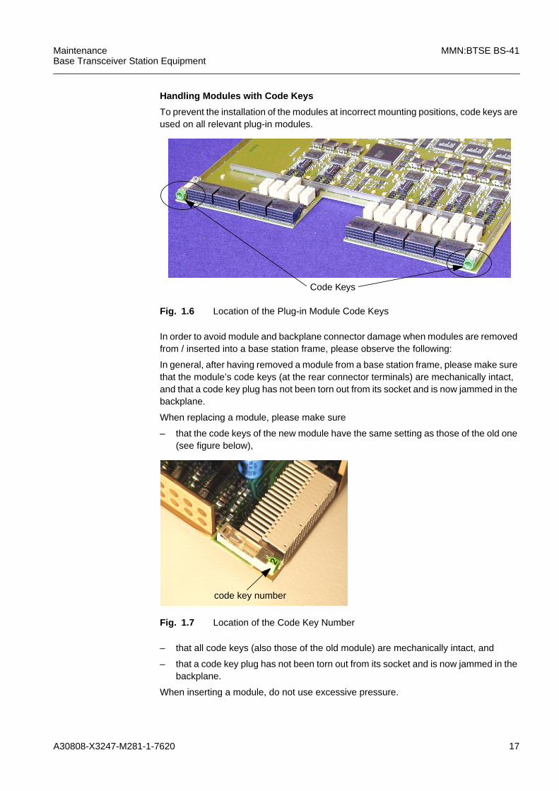
Handling Modules with Code Keys
To prevent the installation of the modules at incorrect mounting positions, code keys areused on all relevant plug-in modules.
Fig. 1.6 Location of the Plug-in Module Code Keys
In order to avoid module and backplane connector damage when modules are removedfrom / inserted into a base station frame, please observe the following:
In general, after having removed a module from a base station frame, please make surethat the module’s code keys (at the rear connector terminals) are mechanically intact,and that a code key plug has not been torn out from its socket and is now jammed in thebackplane.
When replacing a module, please make sure
– that the code keys of the new module have the same setting as those of the old one(see figure below),
Fig. 1.7 Location of the Code Key Number
– that all code keys (also those of the old module) are mechanically intact, and
– that a code key plug has not been torn out from its socket and is now jammed in thebackplane.
When inserting a module, do not use excessive pressure.
Code Keys
2
code key number

18 A30808-X3247-M281-1-7620
MMN:BTSE BS-41 MaintenanceBase Transceiver Station Equipment
1.5.4 Quick Module Replacement
In general, there are 2 replacement procedures:
– the standard replacement procedure
and
– the facilitated, quick replacement procedure (only applicable for some particularmodules).
For the standard replacement procedure, an LMT is required. The modules are lockedand, after their replacement, tested and unlocked via an LMT.
For the quick replacement procedure, an LMT is not required. The module can be re-placed directly and is put into service automatically after a successful replacement (Au-torecovery).Precondition for the quick replacement procedure: the attribute Autorecovery (EAU-TOREC) is enabled.
To check whether this attribute is enabled, perform the LMT command:
BSS
BE Btsep Br<no>:<NE id>
BSS-EQUIPMENT
BTSEP
BTSEP<no>
GET BTSEP NOSWL
REQATTL
EAUTOREC
Get BTSEP NOSWL:NAME=BTSEP:<no>,REQATTL=EAUTOREC
To set this attribute, refer to ITMN:BTSE BS-41, chapter “Setting Attributes for the BT-SE”.
– In order to be able to connect the semi-rigid/flexi cables, insert the prepared moduleas far as necessary. It is recommended to leave about 2 cm (.75’’) distance betweenmodule and backplane connectors.
– Connect all semi-rigid/flexi cables.
– Fully insert the module.
iSpecial Behaviour of Modules that are connected by the CAN bus:If Autorecovery is enabled and such a module is mistakenly locked before it is ex-changed, then this module will recover automatically after it is unlocked.This has no further consequences for the system, but is an unspecified behaviour.
iQuick Replacement Procedure and semi-rigid/flexi CablingModules with semi-rigid/flexi cabling require a special handling!It is important that all semi-rigid/flexi cables are connected before the module is fully in-serted. Otherwise, the module is not put into service. The reason for this is that the au-tomatic recovery process starts as soon as the module comes into contact with thebackplane connectors. Semi-rigid/flexi cables that are not connected during this pro-cess cause errors which will prevent the autorecovery of the module.
A30808-X3247-M281-1-7620 19
MaintenanceBase Transceiver Station Equipment
MMN:BTSE BS-41
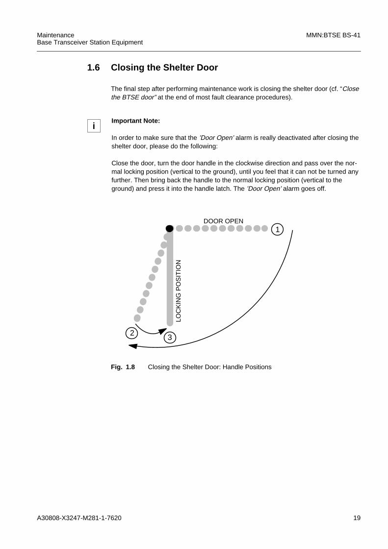
1.6 Closing the Shelter Door
The final step after performing maintenance work is closing the shelter door (cf. “Closethe BTSE door” at the end of most fault clearance procedures).
Fig. 1.8 Closing the Shelter Door: Handle Positions
iImportant Note:
In order to make sure that the ’Door Open’ alarm is really deactivated after closing theshelter door, please do the following:
Close the door, turn the door handle in the clockwise direction and pass over the nor-mal locking position (vertical to the ground), until you feel that it can not be turned anyfurther. Then bring back the handle to the normal locking position (vertical to theground) and press it into the handle latch. The ’Door Open’ alarm goes off.
1
2
LOC
KIN
G P
OS
ITIO
N
DOOR OPEN
3

20 A30808-X3247-M281-1-7620
MMN:BTSE BS-41 MaintenanceBase Transceiver Station Equipment

A30808-X3247-M281-1-7620 21
MaintenanceBase Transceiver Station Equipment
MMN:BTSE BS-41
2 Tasklist
Membrane Filter (MEF)
The MEF is a passive component fitted to the inside of the door. Its purpose is to filterthe air being drawn in by the internal FANs.
Corrosion:
The MEF is made of corrosion resistant materials.
Filter characteristic:
In contrast to a so-called „depth filter“, the MEF does not face the incoming air with afilter tissue but with a smooth membrane surface which offers little chance for dust par-ticles to stick to it irreversibly and no chance to penetrate any further.
This characteristic makes a significant clogging of the filter an unlikely event under nor-mal environmental conditions.
Maintenance routine:
It is recommended to check the air in-let and louvers of a shelter for blocking particles(e.g. leaves).
A MEF must not be cleaned because the membrane might get damaged.
A MEF which is visibly soiled – with no over temperature alarm occurred – does not needto be replaced due to described filter characteristic above.
If an over temperature alarm occurs, check the following before MEF replacement:
or false alarm (e.g. defective cables, ACTC, ACTP)
– check air in-lets for blocking particles
– check for defect FAN(s)
– check for false alarm (e.g. defective cables, ACTC, ACTP)
If all other failure causes could be excluded, the MEF must be replaced by a new oneand the old one sent to the relevant service center.
Note: The symbol on the integral frame indicating the top of the MEF has to be noticedwhen fitting it to the inside of the door.
Heat Exchanger (HEX)
Preventive maintenance for HEX
Dust accumulation may occur on fan impellers and so must be cleaned every 12 monthsto ensure optimum performance and prevent possible vibration which could damage thebearings and reduce its life span.
22 A30808-X3247-M281-1-7620
MMN:BTSE BS-41 MaintenanceBase Transceiver Station Equipment
Recuperator cleaning:
Dust accumulation may occur on recuperator plates, especially the external air-ways,and should be cleaned every 12 months to ensure optimum performance.
In areas of general contamination, the recuperator may be cleaned with compressed airor a powerful vacuum, or in special cases with water spray or a ph-neutral soap/watersolution to the external air-ways only.
For coastal or high contamination areas, it is recommended that the HEX is removedfrom the door of the shelter.
With the HEX unit removed from the door the recuperator can be extensively cleaned.The recuperator does not need to be removed from of the HEX for cleaning.
An exchange of the recuperator is generally not possible.
Water drain of HEX:
Dust sediment may block the drain of the HEX so that water will not pass through theinternal circuit of the shelter. Every 12 months the water drain must be cleared andcleaned to ensure that it is free of contamination.
With the HEX unit removed from the door the water drain may be extensively cleaned.The water drain is via a tube on the lower left side in the housing of the HEX.
Use of water spray and compressed air:
Do not spray water in and around the fans
Use water spray or a ph-neutral soap/water solution only for external air-ways of the re-cuperator.
When using compressed air and/or water spray, be careful not to damage the foam sealbetween the recuperator and the HEX housing.
All residue from the cleaning process should be removed.
HEX Corrosion:
The HEX is corrosion resistant because the housing, recuperator and fan wheel are allmade of plastic.

A30808-X3247-M281-1-7620 23
MaintenanceBase Transceiver Station Equipment
MMN:BTSE BS-41
3 Fault Clearance Procedures for Modules andInterfaces

24 A30808-X3247-M281-1-7620
MMN:BTSE BS-41 MaintenanceBase Transceiver Station Equipment
3.1 Abis
1 Open the BTSE door
To verify an Abis alarm you have to open the BTSE door and check the LEDs ofthe COBA/COSA.
2 Check the LEDs on the COBA/COSA
You can recognize an Abis alarm by the red LEDs for Abis 1 to Abis 8 alarm onthe COBA/COSA.
The Abis LEDs indicate the respective Managed Object BPORT, e.g.:
iIn some cases, Abis alarms originate from loose or damaged PCM cables on the BTSEAbis interface (OVPT) and in the corresponding distribution frame in BSC direction.Therefore, the relevant cables must be checked first, according to the following proce-dure.
Typical Abis alarms concerning cable problems may be indicated by the alarm mes-sage- BPORT - Loss of signal
iBPORT is the logical object that is related to the Abis interface (OVPT).The Abis lines are also referred to as PCM lines.
Abis 1 corresponds to the Managed Object BPORT 0,Abis 2 corresponds to the Managed Object BPORT 1, etc.

A30808-X3247-M281-1-7620 25
MaintenanceBase Transceiver Station Equipment
MMN:BTSE BS-41
3 Optional: Check the active alarms with the LMT
If an LMT is available, you can check the active Abis alarms.
Perform the following command:
b BSS
NE Btsep Br<no>:<NE id>
BSS-EQUIPMENT
BTSEP
BTSEP<no>
GETACTIVEALARMS BTSEP
Getactivealarms BTSEP:NAME=BTSEP:0;
4 Physical check of the Abis / PCM cable connections (OVPT)
Are the Abis / PCM lines fastened correctly
– in the terminal block of the OVPT and
– in the distributing frame in the BSC direction?
Y h...6N h...5
Further information on the Abis interface on the OVPT are documented in theInstallation Manual. ......see IMN:BS-41
5 Fasten the Abis / PCM Lines correctly in their terminals
Did the red LED of the Abis Alarm on the COBA/COSA and CUs turn off?
This may take up to 10 minutes. Y h...9N h...6
All active alarms will be listed in the Message Browser Window.
Typical failure event report for an Abis / PCM cable problem:
NAME = BPORT:0Event Type = Communication Failure EventEvent Time = 26/Jan/2001 00:13:03Probable Cause = Transmission ErrorSpecific Problems = 10270 - Loss of signalSeverity = Major

26 A30808-X3247-M281-1-7620
MMN:BTSE BS-41 MaintenanceBase Transceiver Station Equipment
6 Visual check of the Abis / PCM Lines (OVPT)
Write down the cable colors and their corresponding terminals before discon-necting any cables.
Remove the Abis / PCM lines in the terminal blocks (OVPT and distributingframe in BSC direction) and examine the cables visually for damages. Do yousee a broken or corroded cable, or an insulation, that interrupts the contact? Y h...7
N h...8
7 Repair bad Abis / PCM lines
Repair bad Abis / PCM lines or exchange the Abis / PCM lines
Did the red LED of the Abis Alarm on the COBA/COSA and CUs turn off?
This may take up to 10 minutes. Y h...9N h...8
8 Call TAC
Call TAC to clear the fault.
9 Prepare end of fault clearance
If an LMT was connected, log off the LMT and disconnect the LMT cable.
Close the BTSE door.
END

A30808-X3247-M281-1-7620 27
MaintenanceBase Transceiver Station Equipment
MMN:BTSE BS-41
3.2 ABISCON
1 Go to Procedure “OVPT”
Fault clearance is identical for the modules “ABISCON” and “OVPT”.
Therefore, please refer to the procedure “OVPT”. h...Procedure: 3.36
END

28 A30808-X3247-M281-1-7620
MMN:BTSE BS-41 MaintenanceBase Transceiver Station Equipment
3.3 AC/DC
The managed object ACDCP is related to the DCBCTRL, not to the AC/DC module itselfand therefore exists only once.
In BS-240 II / 240XL II the AC/DC system is not configured as managed object. To makeAC/DC alarms visible, Environmental Alarms have to be configured (see ITMN:BTSEBS-41, Creating the Alarm Configuration (ENVABTSE)).
If the AC/DC modules are not equipped in redundant configuration, the system uses thebackup battery for power supply and may be in ’Emergency Configuration’.
In redundant configuration only one AC/DC module can be replaced at the same timewithout any interruption.
The fault message indicates the address of the corresponding DCBCTRL.
Examples for Alarms in the Power Supply System
Error ID 20495 battery breakdown
Error ID 20496 battery charching fault
Error ID 20497 -48V out of tolerance
Error ID 53266 mains breakdown
1 Interpret the Fault Message ......(see 5.4)
Note the values specified in the fault message, for example:
– Module(s) ??
– BTS-no ??
– Rack-no ??
– Module address ??
Use these values for command input.
Use the logical address to find the mounting location of the module(s). ......(see 4.3)
iNote that the failure cause may be located in any module of the power sypply system:- the module(s) addressed in the error message- AC/DC- AC Panel or ADP- DCBCTRL- BatteryIt is recommended to start with the replacement of the module which is addressed inthe fault message. Afterwards - if the error is still there - to take the other modules inthe power supply system into consideration.
A30808-X3247-M281-1-7620 29
MaintenanceBase Transceiver Station Equipment
MMN:BTSE BS-41
2 Find the Suspected Module
3 Check the LED status of each AC/DC module
Is any red LED illuminated? Y h...7N h...4
4 Check fuses
Disconnect the AC cable from the suspected module
Are the fuses optically and electrically all right? Y h...6N h...5
5 Change fuses
Change the defective fuses (10 A, quick act). h...6
6 Check the Output Current
Does the module supply output current? Y h...11N h...7
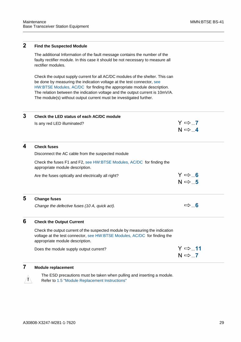
7 Module replacement
The additional Information of the fault message contains the number of thefaulty rectifier module. In this case it should be not necessary to measure allrectifier modules.
Check the output supply current for all AC/DC modules of the shelter. This canbe done by measuring the indication voltage at the test connector, seeHW:BTSE Modules, AC/DC for finding the appropriate module description.The relation between the indication voltage and the output current is 10mV/A.The module(s) without output current must be investigated further.
Check the fuses F1 and F2, see HW:BTSE Modules, AC/DC for finding theappropriate module description.
Check the output current of the suspected module by measuring the indicationvoltage at the test connector, see HW:BTSE Modules, AC/DC for finding theappropriate module description.
!The ESD precautions must be taken when pulling and inserting a module.Refer to 1.5 "Module Replacement Instructions"

30 A30808-X3247-M281-1-7620
MMN:BTSE BS-41 MaintenanceBase Transceiver Station Equipment
1. Disconnect all cables if there are any
2. Pull affected module
3. Select a module with a functional HW / SW state compatible to that of themodule which is being replaced
4. Insert prepared module
5. Connect all cables
8 Run test for replaced (suspected) module
Does the module supply output current? Y h...9N h...12
9 Mark the Replaced Module as Defective
h...10
10 Updating of the Remote Inventory Data
For updating the remote inventory data, refer to procedure “Remote InventoryData Update” in this manual.
i....Procedure:3.39
11 End of Fault Clearance Procedure
Close BTSE door.
12 Reinsert the replaced module
Remove the currently inserted module and reinsert the old (replaced) modulebecause the old module was probably not defective. Refer to the relevant part inthe replacement procedure.
h...13
13 Another Suspected Module/Interface?
Is there another suspected module/interface in the fault message? Y h...14N h...15
14 Replacement Procedure for the Next Suspected Module/Interface
Go to the replacement procedure for the next suspected module/interface. h...Procedure: 3.x
15 Call TAC
h...11
Check the voltage at test connector, see HW:BTSE Modules, AC/DC for find-ing the appropriate module description. Take a voltmeter with test cable.The voltage should be 10mV/A, depending on the load.

A30808-X3247-M281-1-7620 31
MaintenanceBase Transceiver Station Equipment
MMN:BTSE BS-41
END

32 A30808-X3247-M281-1-7620
MMN:BTSE BS-41 MaintenanceBase Transceiver Station Equipment
3.4 ACDCP
ACDCP is a functional part of DCBCTRL and can not be re-placed separately. AC/DC or rectifier errors are also report-ed via the object ACDCP.If the error message reports an AC/DC or rectifier error thenstart the fault clearance procedure with: h 3.3 "AC/DC"Otherwise continue with procedure: h 3.15 "DCBCTRL"

A30808-X3247-M281-1-7620 33
MaintenanceBase Transceiver Station Equipment
MMN:BTSE BS-41
3.5 ACT
1 Interpret the Fault Message ...... (see 5.4)
Note the values specified in the fault message, for example:
– Module(s) ??
– BTS-no ??
– Rack-no ??
– Module address ??
Use these values for command input.
Use the logical address to find the mounting location of the module(s). ...... (see 4.3)
2 Autorecovery (EAUTOREC) enabled?
Is the attribute Autorecovery (EAUTOREC) enabled? Y h...3N h...6
If you have no information on this attribute, continue with “N”.
3 Quick Module Replacement
iThe module ACT consists of: ACTA, ACTC and ACTP.The ACTC can be changed only together with the DC Panel.
!The ESD precautions must be taken when pulling and inserting a module.Refer to 1.5 "Module Replacement Instructions".

34 A30808-X3247-M281-1-7620
MMN:BTSE BS-41 MaintenanceBase Transceiver Station Equipment
1. Disconnect all cables on ACTA and ACTP, see HW:BTSE Modules, ACT forfinding the appropriate module description.
2. Unscrew ACTA and ACTP module.
3. Pull ACTA and ACTP module.
4. Select the modules with a functional HW / SW state compatible to that of themodules which are being replaced.
5. Check the DIP switch settings against the replaced module, see HW:BTSEModules, ACT for finding the appropriate module description.
6. Insert prepared modules.
7. Tighten the prepared modules.
8. Connect all cables.
– Replacement successful h...4– Replacement not successful h...13
4 Mark the Replaced Module as defective
h...5
5 End of Fault Clearance Procedure
If an LMT was connected, log off the LMT and pull the LMT cable out of the
socket.
Close the BTSE door.
6 Connect the LMT to the BTSE
Plug the LMT cable into the corresponding socket. ......(see Fig. 4.4)
Start LMT Login - Procedure (refer to LMT description).
Was the module replacement successful?All LEDs must signal normal operation (no red LEDs may be on).Call OMC to make sure that the BTSE has gone back to normal operation.
A30808-X3247-M281-1-7620 35
MaintenanceBase Transceiver Station Equipment
MMN:BTSE BS-41
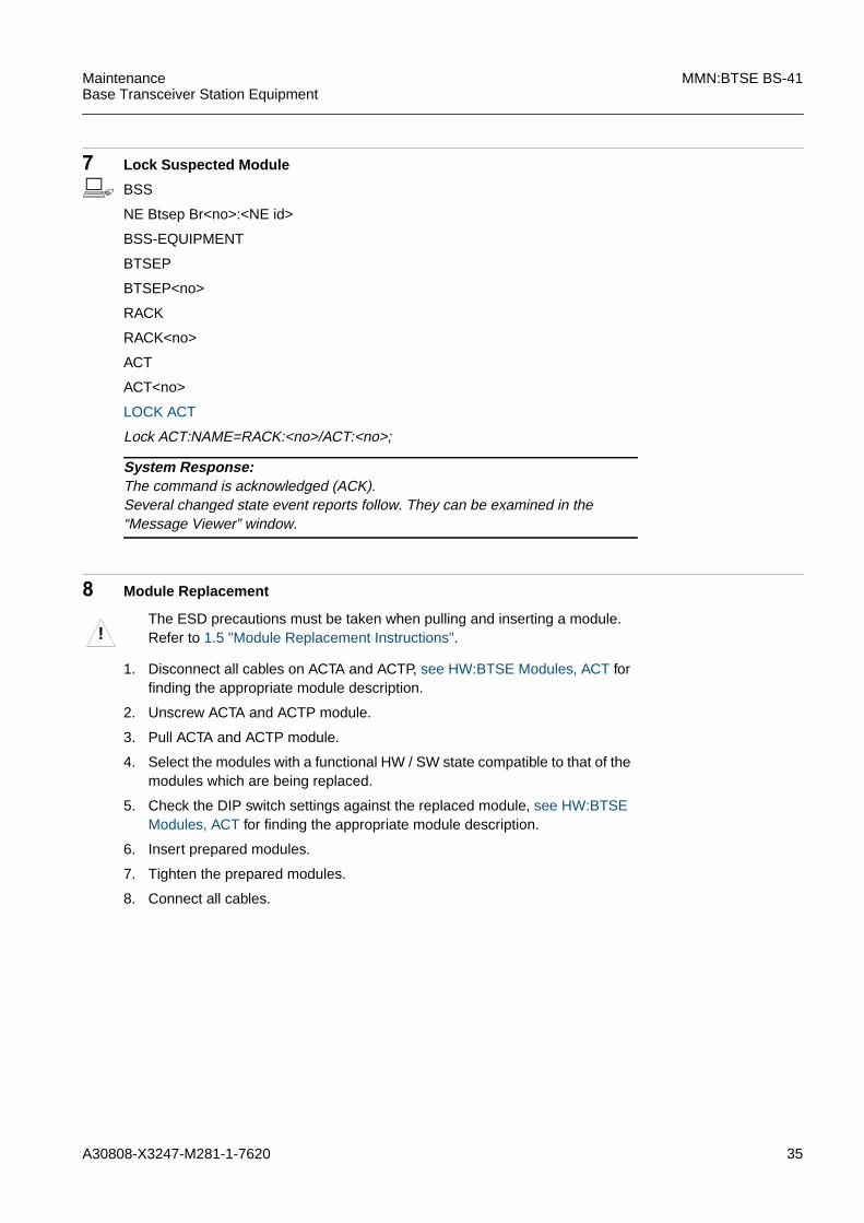
7 Lock Suspected Module
b BSS
NE Btsep Br<no>:<NE id>
BSS-EQUIPMENT
BTSEP
BTSEP<no>
RACK
RACK<no>
ACT
ACT<no>
LOCK ACT
Lock ACT:NAME=RACK:<no>/ACT:<no>;
8 Module Replacement
1. Disconnect all cables on ACTA and ACTP, see HW:BTSE Modules, ACT forfinding the appropriate module description.
2. Unscrew ACTA and ACTP module.
3. Pull ACTA and ACTP module.
4. Select the modules with a functional HW / SW state compatible to that of themodules which are being replaced.
5. Check the DIP switch settings against the replaced module, see HW:BTSEModules, ACT for finding the appropriate module description.
6. Insert prepared modules.
7. Tighten the prepared modules.
8. Connect all cables.
System Response:The command is acknowledged (ACK).Several changed state event reports follow. They can be examined in the“Message Viewer” window.
!The ESD precautions must be taken when pulling and inserting a module.Refer to 1.5 "Module Replacement Instructions".

36 A30808-X3247-M281-1-7620
MMN:BTSE BS-41 MaintenanceBase Transceiver Station Equipment
9 Run Test for Replaced Module
b BSS
NE Btsep Br<no>:<NE id>
BSS-EQUIPMENT
BTSEP
BTSEP<no>
RACK
RACK<no>
ACT
ACT<no>
PERFTEST ACT
Perftest ACT:NAME=RACK:<no>/ ACT:<no> ;
Is the test outcome as follows?
– Test Outcome = passed h...10– Test Outcome = failed h...13
10 Mark the Replaced Module as defective
System Response:The command is acknowledged (ACK).
Test Result:The test report can be examined in the “Message Viewer” window.Note the test outcome.If the test outcome is "fail", some more information is given, such as "ProposedRepair Action" etc.

A30808-X3247-M281-1-7620 37
MaintenanceBase Transceiver Station Equipment
MMN:BTSE BS-41
11 Unlock Suspected Module
b BSS
NE Btsep Br<no>:<NE id>
BSS-EQUIPMENT
BTSEP
BTSEP<no>
RACK
RACK<no>
ACT
ACT<no>
UNLOCK ACT
Unlock ACT:NAME=RACK:<no>/ACT:<no>;
12 End of Fault Clearance Procedure
Log off the LMT and pull the LMT cable out of the socket.
Close the BTSE door.
13 Reinsert the Replaced Module
Remove the currently inserted module and reinsert the old (replaced) modulebecause the old module was probably not defective. Refer to the relevant part inthe replacement procedure.
h...14
14 Next suspected module
Is one of the suspected modules not yet replaced? Y h...15N h...16
15 Replacement Procedure for the Next Suspected Module/Interface
Go to the replacement procedure for the next suspected module/interface. h...Procedure: 3.x
16 Unsuccessful module replacement
Call TAC.
END
System Response:The command is acknowledged (ACK).Several changed state event reports follow. They can be examined in the“Message Viewer” window.

38 A30808-X3247-M281-1-7620
MMN:BTSE BS-41 MaintenanceBase Transceiver Station Equipment
3.6 Battery
The fault message indicates the address of the corresponding DCBCTRL.
1 Interpret the Fault Message ......(see 5.4)
Note the values specified in the fault message, for example:
– Module(s) ??
– BTS-no ??
– Rack-no ??
– Module address ??
Use these values for command input.
Use the logical address to find the mounting location of the module(s). ......(see Fig. 4.4)
2 Connect the LMT to the BTSE
Plug the LMT cable into the corresponding socket. ......(see Fig. 4.4)
Start LMT Login - Procedure (refer to LMT description).
3 Lock suspected module
b BSS
NE Btsep Br<no>:<NE id>
BSS-EQUIPMENT
BTSEP
BTSEP<no>
RACK
RACK<no>
BATTERY
BATTERY<no>
LOCK BATTERY
Lock BATTERY:NAME=RACK:<no>/BATTERY:<no>;
System Response:The command is acknowledged (ACK).Several changed state event reports follow. They can be examined in the“Message Viewer” window.

A30808-X3247-M281-1-7620 39
MaintenanceBase Transceiver Station Equipment
MMN:BTSE BS-41
4 Module replacement
1. Disconnect the battery cables coming from AC/DC converters, see HW:BT-SE Frames, F:Battery4 for finding the appropriate module description.
2. Disconnect the batteries by removing pre-fabricated short wire bridges.
3. Remove the air vent kit.
4. Open both fixing straps.
5. Remove the affected module.
6. Select a module of the same manufacturer to that of the module which isbeing replaced (check also DIP switches for manufacturer on DCBCTRL).
7. Insert the prepared module.
8. Setup the 4 batteries on the battery tray.
9. Close and tighten both fixing straps.
10. Setup the air vent kit and route the outlet tube through the cable feedingmodule.
11. Connect the batteries by pre-fabricated short wire bridges.
12. Connect the battery cables coming from AC/DC converters.
!The ESD precautions must be taken when pulling and inserting a module.Refer to 1.5 "Module Replacement Instructions".
!Pay attention to the sequence of the steps to avoid shorts.

40 A30808-X3247-M281-1-7620
MMN:BTSE BS-41 MaintenanceBase Transceiver Station Equipment
5 Run Test for Replaced Module
b BSS
NE Btsep Br<no>:<NE id>
BSS-EQUIPMENT
BTSEP
BTSEP<no>
RACK
RACK<no>
BATTERY
BATTERY<no>
PERFTEST BATTERY
Perftest BATTERY:NAME=RACK:<no>/BATTERY:<no>;
Is the test outcome as follows?
– Test Outcome = Pass h...6– Test Outcome = Fail h...10
6 Mark the Replaced Module as Defective
7 Updating of the Remote Inventory Data
For updating the remote inventory data refer to procedure “Remote InventoryData Update” in this manual.
h...Procedure: 3.39
System Response:The command is acknowledged (ACK).
Test Result:The test report can be examined in the “Message Viewer” window.Note the test outcome.If the test outcome is "fail", some more information is given, such as "ProposedRepair Action" etc.
A30808-X3247-M281-1-7620 41
MaintenanceBase Transceiver Station Equipment
MMN:BTSE BS-41
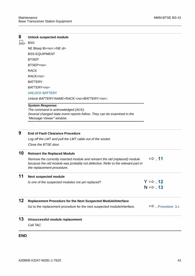
8 Unlock suspected module
b BSS
NE Btsep Br<no>:<NE id>
BSS-EQUIPMENT
BTSEP
BTSEP<no>
RACK
RACK<no>
BATTERY
BATTERY<no>
UNLOCK BATTERY
Unlock BATTERY:NAME=RACK:<no>/BATTERY:<no>;
9 End of Fault Clearance Procedure
Log off the LMT and pull the LMT cable out of the socket.
Close the BTSE door.
10 Reinsert the Replaced Module
Remove the currently inserted module and reinsert the old (replaced) modulebecause the old module was probably not defective. Refer to the relevant part inthe replacement procedure.
h...11
11 Next suspected module
Is one of the suspected modules not yet replaced? Y h...12N h...13
12 Replacement Procedure for the Next Suspected Module/Interface
Go to the replacement procedure for the next suspected module/interface. h...Procedure: 3.x
13 Unsuccessful module replacement
Call TAC.
END
System Response:The command is acknowledged (ACK).Several changed state event reports follow. They can be examined in the“Message Viewer” window.

42 A30808-X3247-M281-1-7620
MMN:BTSE BS-41 MaintenanceBase Transceiver Station Equipment
3.7 BPORT
BPORT errors are reported via the object Abis.For error correction continue with procedure: h 3.1 "Abis"

A30808-X3247-M281-1-7620 43
MaintenanceBase Transceiver Station Equipment
MMN:BTSE BS-41
3.8 COBA Without CORE Redundancy
1 Interpret the Fault Message ...... (see 5.4)
Note the values specified in the fault message, for example:
– Module(s) ??
– BTS-no ??
– Rack-no ??
– Module address ??
Use these values for command input.
Use the logical address to find the mounting location of the module(s). ...... (see Fig. 4.4)
2 Connect the LMT to the BTSE
Plug the LMT cable into the corresponding socket.
Start LMT Login procedure (refer to LMT description).
3 Switch off COBA module
Switch off the COBA with the corresponding breaker on the DC Panel.
!A mix of module types COBA2P8 / COSA6P16 with module types COBA4P12 /COSA4P12 in one rack is not allowed - even in the status “power off”.
!These modules are equipped with electrostatically sensitive components and aresusceptible to damage by electrostatic discharge. Follow ESD precautions when re-moving and inserting modules. Refer to 1.5.1 "ESD Precautions".
!When the COBA4P12 is inserted, a module COSA4P12 or COREXT must also beequipped. Check if one of these modules is equipped and insert if necessary.
iThis procedure describes COBA4P12/COBA4P12 or COBA2P8/COBA2P8replacement without CORE redundancy.For COBA2P8/COBA4P12 replacement or COBA with redundancy, please see:
- 3.11 "COBA2P8 - COBA4P12 With CORE Redundancy"- 3.10 "COBA2P8 - COBA4P12 Without CORE Redundancy"- 3.9 "COBA With CORE Redundancy"
iModule COBA may be removed while the power is on.
44 A30808-X3247-M281-1-7620
MMN:BTSE BS-41 MaintenanceBase Transceiver Station Equipment
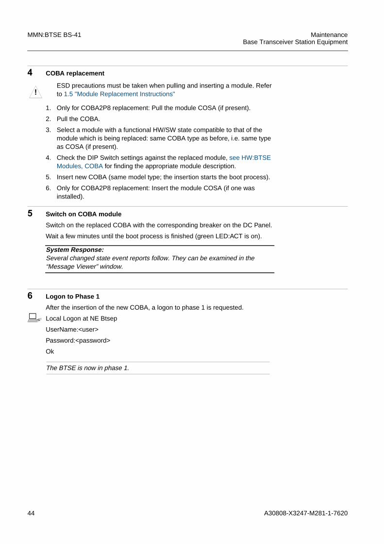
4 COBA replacement
1. Only for COBA2P8 replacement: Pull the module COSA (if present).
2. Pull the COBA.
3. Select a module with a functional HW/SW state compatible to that of themodule which is being replaced: same COBA type as before, i.e. same typeas COSA (if present).
4. Check the DIP Switch settings against the replaced module, see HW:BTSEModules, COBA for finding the appropriate module description.
5. Insert new COBA (same model type; the insertion starts the boot process).
6. Only for COBA2P8 replacement: Insert the module COSA (if one wasinstalled).
5 Switch on COBA module
Switch on the replaced COBA with the corresponding breaker on the DC Panel.
Wait a few minutes until the boot process is finished (green LED:ACT is on).
6 Logon to Phase 1
After the insertion of the new COBA, a logon to phase 1 is requested.
b Local Logon at NE Btsep
UserName:<user>
Password:<password>
Ok
The BTSE is now in phase 1.
!ESD precautions must be taken when pulling and inserting a module. Referto 1.5 "Module Replacement Instructions"
System Response:Several changed state event reports follow. They can be examined in the“Message Viewer” window.

A30808-X3247-M281-1-7620 45
MaintenanceBase Transceiver Station Equipment
MMN:BTSE BS-41
7 Format BTSEP FLASH EPROM
b BSS
NE Btsep Br<no>:<NE id>
BSS-EQUIPMENT
BTSEP
BTSEP<no>
FORMAT BTSEP FLASH
Format BTSEP FLASH:NAME=BTSEP:0;
8 SW Download and Activation
After the COBA replacement, the BTSE specific data base for this COBA is lostand it is necessary to download and activate the SW again.
Perform the procedure SW Download and Activation. i ... ITMN:BTSEBS-41
9 Automatic switch to Phase 2
After the SW download and activation, the BTSE will automatically request toswitch to phase 2. Logon to phase 2:
b Local Logon at NE Btsep
UserName:<user>
Password:<password>
Ok
The BTSE is now in phase 2.
10 Reconfigure the BTSE
After the COBA replacement, the BTSE specific data base will be lost. Thismakes it necessary to reconfigure the BTSE. Usually, a backup copy of the con-figuration is stored with the site specific documentation.
Is a backup copy of the site specific configuration available? Y h...12N h...11
iFor COBA4P12 replacement: This process will take a few minutes. Pleasewait until the process has finished.
System Response:The command result “Operation successful” is displayed in the “MessageViewer” window. Several changed state event reports follow.

46 A30808-X3247-M281-1-7620
MMN:BTSE BS-41 MaintenanceBase Transceiver Station Equipment
11 Start installation procedure
If no backup copy is available, the BTSE must be reconfigured by hand.
Repeat all tasks for the BTSE installation as described in the ITMN:BTSE. ......ITMN:BTSEBS-41
Was the installation successful? Y h...14N h...30
12 Copy the backup script files to the BKBTS\BTSPLUS directory
13 Restore the HW Configuration
1. Select “View” -> “Restore BTS” in the menu or click on the restore BTS iconin the tool bar menu. The “Restore BTS” window is prompted and the restoreprocedure is ready to start.
2. Click on the “Restore” button. At the end of the restore procedure, the oper-ator can choose to repeat it or to go on working with the LMT.
3. Click on the “Ok” button to finish the process.
Was the operation successful? Y h...14N h...30
14 Restore the Remote Inventory Data
It is necessary to rebuild the inventory data that was stored on the removedCOBA using a backup IDF file. Usually, a backup of the IDF is stored on site withthe site specific information. If there is no backup file, the data can be extractedfrom the BSC IDF file via TAC, or can be restored manually.
Inventory data restore via backup file stored on site? h...17Inventory data restore via extraction of the IDF data from the BSC IDF? h...16Inventory data restore by hand? h...15
15 Create all nob_RIUs manually
For the creation of the inventory data for all nob_RIUs, refer to the ITMN:BTSE,chapter “Procedures”.
......ITMN:BTSEBS-41
Continue with the download and backup storage of the inventory data. h...20
Copy the 6 backup script files “script*p.lmt” from the disk to the harddisk of theLMT PC e.g., C:\...\LMT<version>\BKBTS\BtsPlus.

A30808-X3247-M281-1-7620 47
MaintenanceBase Transceiver Station Equipment
MMN:BTSE BS-41
16 Extract BTSE data from BSC IDF
Call TAC to have the data extracted from the BSC IDF. Save the file to the hard-disk of the LMT PC e.g., C:\...\LMT<version>\IDF\*.idf.
Continue with step.. h...18
17 Copy IDF file to LMT PC
18 Start IDF Editor
b To start the IDF Editor select “IDF GSM” -> “IDF Editor” from the Windowsprogram menu.
19 Open IDF File
b To open the IDF file:
1. Select “File” -> “Open” from the menu of the IDF Evolution.
2. Enter path and file name of the IDF-file or select the file from the list in theappearing window.
3. Double-click on the file name or click on the “Open” button after selecting thefile name.
20 Export nob_RIU File
Only the nob_RIU-part has to be exported for the download to the BTSE.
b To export the nob_RIU data:
1. Select “Export” > “NOB” from the menu.
2. A window opens in which you can edit the file name and select the directoryin which the file is saved. By default, the file name is composed of the “SalesUniqueName” with the extension “.nob”. Edit the file name and select thesource directory or confirm the default name and directory by clicking on the“Save” button.
3. The nob_RIU data are exported to the NOB file. The selected destinationpath of this file is displayed in an attention window. Confirm by clicking on the“OK” button.
4. A question window is displayed: “Create BTS_NRIU for download?” Click onthe “Yes” button.
Copy the IDF backup file from the disk to the harddisk of the LMT PC e.g.,C:\...\LMT<version>\IDF\*.idf.

48 A30808-X3247-M281-1-7620
MMN:BTSE BS-41 MaintenanceBase Transceiver Station Equipment
21 Download nob_RIU File to BTSE
Change to the LMT Evolution main window.
b BSS
NE Btsep Br<no>:<NE id>
BSS-EQUIPMENT
BTSEP
BTSEP:<no>
REMINV
REMINV:<no>
DNLIDFD REMINV
SRCDIR=<source directory>
SRCDIR: enter the source directory in which the exported NOB-file was saved,for example C:...\LMT<version>\Idf\Dnload.
Dnlidfd REMINV:NAME:=REMINV:0,SRCDIR=”...”;
System Response:The command result “OPERATION COMPLETED” is displayed in the“Message Viewer” window.

A30808-X3247-M281-1-7620 49
MaintenanceBase Transceiver Station Equipment
MMN:BTSE BS-41
22 Upload IDT-File from BTSE
Now you must upload the Remote Inventory Data that are stored in the BTSE(IDT file) to the LMT PC in order to create an up-to-date IDF file for backup.
b BSS
NE Btsep Br<no>:<NE id>
BSS-EQUIPMENT
BTSEP
BTSEP:<no>
REMINV
REMINV:<no>
UPLLIDF REMINV
DESTDIR=<path>
FILE=<file name>
OVERWRITE=YES
Additional Information: The attributes DESTDIR and FILE are optional. If nospecial path or file name is entered, the file is uploaded to the default directory:C:\...\LMT<version>\IDF\upload,OVERWRITE=<yes> of the IDF Editor. If theattribute OVERWRITE=<yes> is selected, a former version of an uploaded IDTfile will be overwritten.
Upllidf REMINV:DESTDIR=”<for example: C:...\LMT<version>\Idf\Up-load”>,FILE=<for example: “btse.idt”>,OVERWRITE= YES;
System Response:In the “Message Viewer” window, the command result is displayed:“OPERATION COMPLETED”.

50 A30808-X3247-M281-1-7620
MMN:BTSE BS-41 MaintenanceBase Transceiver Station Equipment
23 Open the Uploaded File
Change to the IDF Editor main window.
b Open the uploaded file:
– Select “File” -> “Open” in the menu.
– Select the uploaded file from the list in the appearing window; e.g.,:<C:...\LMT<version>\Idf\Upload\BTSE.idt”>.
– Click on the “Open” button.
24 Export IDF file for Backup
Now you must create an IDF file for backup.
b To export the Remote Inventory Data for backup:
1. Select “Export” -> "IDF" from the menu.
2. Select the destination path in the appearing window, preferably “A:\”. The filename is automatically composed of the “SalesUniqueName” with theextension “.idf”.
3. Click on the “Save” button.
4. Put the disk with the backup file of the inventory data to the site specificdocumentation.
25 Connect BTS site manager to the BSC / switch from Phase 2 to Phase 3
b BSS
NE Btsep Br<no>:<NE id>
BSS-FUNCTIONAL
BTSM
BTSM:<no>
CONNBSC BTSM
NAME=BTSM:0
Connbsc BTSM:NAME=BTSM:0;
26 Logon
b Local Logon at NE Btse
UserName:<user>
Password:<password>
Ok
The BTSE is now in phase 3. The BSC will start the alignment with the BTSE.
System Response:The command is acknowledged (ACK).Several changed state event reports follow. They can be examined in the“Message Viewer” window.

A30808-X3247-M281-1-7620 51
MaintenanceBase Transceiver Station Equipment
MMN:BTSE BS-41
27 Result of Module Replacement
The module replacement was successful if the LEDs signal normal operation, ifthere are no relevant active alarms, and if the object details for the COBA are asfollows:
Was the module replacement successful? Y h...28N h...30
28 Mark the replaced module as defective
29 End of Fault Clearance Procedure
Log off the LMT and pull the LMT cable out of the socket.
Close the BTSE door.
30 Unsuccessful Module Replacement
Call TAC.
END
Availability Status Null
Operational State Enabled
Administrative State Unlocked

52 A30808-X3247-M281-1-7620
MMN:BTSE BS-41 MaintenanceBase Transceiver Station Equipment

A30808-X3247-M281-1-7620 53
MaintenanceBase Transceiver Station Equipment
MMN:BTSE BS-41
3.9 COBA With CORE Redundancy
1 Interpret the Fault Message ...... (see 5.4)
Note the values specified in the fault message, for example:
– Module(s) ??
– BTS-no ??
– Rack-no ??
– Module address ??
Use these values for command input.
Use the logical address to find the mounting location of the module(s). ...... (see Fig. 4.4)
2 Connect the LMT to the BTSE
Plug the LMT cable into the corresponding socket.
Start LMT Login procedure (refer to LMT description).
!A mix of module types COBA2P8 / COSA6P16 with module types COBA4P12 /COSA4P12 in one rack is not allowed - even in the status “power off”.
!These modules are equipped with electrostatically sensitive components and aresusceptible to damage by electrostatic discharge. Follow ESD precautions when re-moving and inserting modules. Refer to 1.5.1 "ESD Precautions".
!When the COBA4P12 is inserted, a module COSA4P12 or COREXT must also beequipped. Check if one of these modules is equipped and insert if necessary.
iThis procedure describes COBA4P12/COBA4P12 or COBA2P8/COBA2P8replacement with CORE redundancy.For other COBA replacements see:
- 3.11 "COBA2P8 - COBA4P12 With CORE Redundancy"- 3.10 "COBA2P8 - COBA4P12 Without CORE Redundancy"- 3.8 "COBA Without CORE Redundancy"
iModule COBA may be removed while the power is on.
iImportantDue to core redundancy, the data of both COBAs must be consistent and equal. If thedata of both COBAs are not consistent and equal, proper operation of the BTSE is notguaranteed in case of an automatic switch due to a COBA/COSA failure.

54 A30808-X3247-M281-1-7620
MMN:BTSE BS-41 MaintenanceBase Transceiver Station Equipment
3 BTSE Backup Files Generation
After the COBA replacement, the BTSE specific data base for this COBA is lostand it is necessary to reconfigure the BTSE. Therefore, backup files that aregenerated from the redundant COBA can be used.
Perform the procedure “BTS Backup Files Generation” described in the ITMN inorder to generate BTSE Backup Files from the redundant COBA.
i....ITMN:BTSEBS-41
If, for some reason, the backup file generation has failed, proceed with theCOBA replacement procedure without redundancy.
4 Upload IDT File from BTSE
After the COBA replacement, the Remote Inventory Data is lost and must be re-built with a backup IDF file. The Remote Inventory Data have to be loaded to theLMT PC from the BTSE due to the redundant COBA.
b BSS
NE Btsep Br<no>:<NE id>
BSS-EQUIPMENT
BTSEP
BTSEP<no>
REMINV
REMINV<no>
UPLLIDF REMINV
DESTDIR=<path>
FILE=<file name>
OVERWRITE=YES
UPLLIDF REMINV:NAME=REMINV:0,DESTDIR="C:\...\LMT<version>\Idf\Up-load”,FILE=”btse.idt”,OVERWRITE=YES;
If, for some reason, the IDF backup file upload has failed, proceed with theCOBA replacement procedure without redundancy.
The values DESTDIR and FILE are optional. If no special path or file name isentered, the file is uploaded to the default directory of the IDF editor.If the value OVERWRITE=YES is selected, a former version of an uploaded IDTfile will be overwritten.
Example: <path>=C:\...\LMT<version>\Idf\Upload; <file name> =btse.idtThe extension “idt” is recommended.
System Response:In the “Message Viewer” window, the command result is displayed:“OPERATION COMPLETED”.

A30808-X3247-M281-1-7620 55
MaintenanceBase Transceiver Station Equipment
MMN:BTSE BS-41
5 Determine the inactive COBA module
Proceed with the inactive COBA module.
6 COBA replacement
Check the LEDs “FLOC” on both COBAs, see HW:BTSE Modules, COBA:The COBA, on which the LED “FLOC” is not on, is the inactive (suspected)COBA. Also, the blinking of the other LEDs at the active COBA is higher fre-quent than at the inactive COBA.
At the LMT view, the inactive COBA is marked with a blue indicator:
!The ESD precautions must be taken when pulling and inserting a module.Refer to 1.5 "Module Replacement Instructions"

56 A30808-X3247-M281-1-7620
MMN:BTSE BS-41 MaintenanceBase Transceiver Station Equipment
1. Only for COBA2P8 replacement: Pull the module COSA (if present).
2. Pull the affected module (inactive COBA).
3. Select a module with a functional HW/SW state compatible to that of themodule which is being replaced: same COBA type as before.
4. Check the DIP Switch settings against the replaced module, see HW:BTSEModules, COBA for finding the appropriate module description.
5. Insert new module (same COBA type; the insertion starts the boot process).
6. Only for COBA2P8 replacement: Insert the module COSA (if one wasinstalled).
7. Wait a few minutes until the boot process is finished (green LED:ACT is on),see HW:BTSE Modules, COBA for finding the appropriate module descrip-tion.
7 Switch the COBA status of the replaced COBA from inactive to active
Switch the inactive COBA to active status to avoid an “automatic redundancyswitch”. The replaced COBA must be active. The formerly redundant (active)COBA is now inactive.
b BSS
NE Btsep Br<no>:<NE id>
BSS-EQUIPMENT
BTSEPs
BTSEP<no>
RACK
RACK<no>
COBA
COBA<no>
SWITCH COBA
Switch COBA:NAME=RACK:0/COBA:0;
8 Switch off the inactive COBA module
Switch off the inactive (previously redundant) COBA with the correspondingbreaker on the DC Panel to avoid an “automatic redundancy switch”.
System Response:Several changed state event reports follow. They can be examined in the“Message Viewer” window.
System Response:The command is acknowledged (ACK).Several changed state event reports follow. They can be examined in the“Message Viewer” window.

A30808-X3247-M281-1-7620 57
MaintenanceBase Transceiver Station Equipment
MMN:BTSE BS-41
9 Automatic disconnection from BSC / Logon to Phase 1
With the switch of the COBA status, the BTS site manager will automatically bedisconnected from the BSC and switched from phase 3 to phase 1 with the fol-lowing logon.
b Local Logon at NE Btsep
UserName:<user>
Password:<password>
Ok
The BTSE is now in phase 1.
10 Format BTSEP FLASH EPROM
b BSS
NE Btsep Br<no>:<NE id>
BSS-EQUIPMENT
BTSEP
BTSEP<no>
FORMAT BTSEP FLASH
Format BTSEP FLASH:NAME=BTSEP:0;
11 SW Download and Activation
After the COBA replacement, the BTSE specific data base for this COBA is lostand it is necessary to download and activate the SW again.
Perform the procedure SW Download and Activation (ITMN:BTSE). i ... ITMN:BTSEBS-41
iFor COBA4P12 replacement: This process will take a few minutes. Pleasewait until the process has finished.
System Response:The command result “Operation successful” is displayed in the “MessageViewer” window. Several changed state event reports follow.
58 A30808-X3247-M281-1-7620
MMN:BTSE BS-41 MaintenanceBase Transceiver Station Equipment
12 Automatic switch to Phase 2
After the SW download and activation, the BTSE will automatically request toswitch to phase 2. Logon to phase 2:
b Local Logon at NE Btsep
UserName:<user>
Password:<password>
Ok
The BTSE is now in phase 2.
13 Restore the HW Configuration
1. Select “View” -> “Restore BTS” in the menu or click on the restore BTS iconin the tool bar menu. The “Restore BTS” window is prompted and the restoreprocedure is ready to start.
2. Click on the “Restore” button. At the end of the restore procedure, the oper-ator can choose to repeat it or to go on working with the LMT.
3. Click on the “Ok” button to finish the process.
Was the operation successful? Y h...14N h...27
14 Start IDF Editor
b To start the IDF Editor select “IDF GSM” -> “IDF Editor” from the Windowsprogram menu.
15 Open IDF File
b To open the IDF file:
1. Select “File” -> “Open” from the menu of the IDF Evolution.
2. Enter path and file name of the IDF-file or select the file from the list in theappearing window.
3. Double-click on the file name or click on the “Open” button after selecting thefile name.
A30808-X3247-M281-1-7620 59
MaintenanceBase Transceiver Station Equipment
MMN:BTSE BS-41
16 Export nob_RIU File
Only the nob_RIU-part has to be exported for the download to the BTSE.
b To export the nob_RIU data:
1. Select “Export” > “NOB” from the menu.
2. A window opens in which you can edit the file name and select the directoryin which the file is saved. By default, the file name is composed of the “SalesUniqueName” with the extension “.nob”. Edit the file name and select thesource directory or confirm the default name and directory by clicking on the“Save” button.
3. The nob_RIU data are exported to the NOB file. The selected destinationpath of this file is displayed in an attention window. Confirm by clicking on the“OK” button.
4. A question window is displayed: “Create BTS_NRIU for download?” Click onthe “Yes” button.
17 Download nob_RIU File to BTSE
Change to the LMT Evolution main window.
b BSS
NE Btsep Br<no>:<NE id>
BSS-EQUIPMENT
BTSEP
BTSEP:<no>
REMINV
REMINV:<no>
DNLIDFD REMINV
SRCDIR=<source directory>
SRCDIR: enter the source directory in which the exported NOB-file was saved,for example C:...\LMT<version>\Idf\Dnload.
Dnlidfd REMINV:NAME:=REMINV:0,SRCDIR=”...”;
System Response:The command result “OPERATION COMPLETED” is displayed in the“Message Viewer” window.

60 A30808-X3247-M281-1-7620
MMN:BTSE BS-41 MaintenanceBase Transceiver Station Equipment
18 Upload IDT-File from BTSE
Now you must upload the Remote Inventory Data that are stored in the BTSE(IDT file) to the LMT PC in order to create an up-to-date IDF file for backup.
b BSS
NE Btsep Br<no>:<NE id>
BSS-EQUIPMENT
BTSEP
BTSEP:<no>
REMINV
REMINV:<no>
UPLLIDF REMINV
DESTDIR=<path>
FILE=<file name>
OVERWRITE=YES
Additional Information: The attributes DESTDIR and FILE are optional. If nospecial path or file name is entered, the file is uploaded to the default directory:C:\...\LMT<version>\IDF\upload,OVERWRITE=<yes> of the IDF Editor. If theattribute OVERWRITE=<yes> is selected, a former version of an uploaded IDTfile will be overwritten.
Upllidf REMINV:DESTDIR=”<for example: C:...\LMT<version>\Idf\Upload”>,FILE=<for example: “btse.idt”>,OVERWRITE= YES;
System Response:In the “Message Viewer” window, the command result is displayed:“OPERATION COMPLETED”.

A30808-X3247-M281-1-7620 61
MaintenanceBase Transceiver Station Equipment
MMN:BTSE BS-41
19 Open the Uploaded File
Change to the IDF Editor main window.
b Open the uploaded file:
– Select “File” -> “Open” in the menu.
– Select the uploaded file from the list in the appearing window; e.g.,:<C:...\LMT<version>\Idf\Upload\BTSE.idt”>.
– Click on the “Open” button.
20 Export IDF file for Backup
Now you must create an IDF file for backup.
b To export the Remote Inventory Data for backup:
1. Select “Export” -> "IDF" from the menu.
2. Select the destination path in the appearing window, preferably “A:\”. The filename is automatically composed of the “SalesUniqueName” with theextension “.idf”.
3. Click on the “Save” button.
4. Put the disk with the backup file of the inventory data to the site specificdocumentation.
21 Connect BTS site manager to the BSC / switch from Phase 2 to Phase 3
b BSS
NE Btsep Br<no>:<NE id>
BSS-FUNCTIONAL
BTSM
BTSM:<no>
CONNBSC BTSM
NAME=BTSM:0
Connbsc BTSM:NAME=BTSM:0;
22 Logon
b Local Logon at NE Btse
UserName:<user>
Password:<password>
Ok
The BTSE is now in phase 3. The BSC will start the alignment with the BTSE.
System Response:The command is acknowledged (ACK).Several changed state event reports follow. They can be examined in the“Message Viewer” window.
62 A30808-X3247-M281-1-7620
MMN:BTSE BS-41 MaintenanceBase Transceiver Station Equipment
23 Switch on the COBA module that was switched off before
Switch on the COBA module with the corresponding breaker on the DC Panel.
24 Result of Module Replacement
The module replacement was successful if the LEDs signal normal operation, ifthere are no relevant active alarms, and if the object details for the COBA are asfollows:
Was the module replacement successful? Y h...25N h...27
25 Mark the replaced module as defective
26 End of Fault Clearance Procedure
Log off the LMT and pull the LMT cable out of the socket.
Close the BTSE door.
27 Unsuccessful Module Replacement
Call TAC.
END
System Response:COBA: State:“Enabled” is shown in the “Object Details” window.
Availability Status Null
Operational State Enabled
Administrative State Unlocked

A30808-X3247-M281-1-7620 63
MaintenanceBase Transceiver Station Equipment
MMN:BTSE BS-41
3.10 COBA2P8 - COBA4P12 Without CORE Redundancy
1 Log on LMT
Connect the LMT to the BTSE and start the log on procedure.
2 Power Off COBA8P2 (and COSA6P16 if present)
Switch off the COBA (and COSA if present) with the corresponding breaker(s)on the DC Panel.
3 Replace COBA2P8 with COBA4P12
!A mix of module types COBA2P8 / COSA6P16 with module types COBA4P12 /COSA4P12 in one rack is not allowed - even in the status “power off”.
!These modules are equipped with electrostatically sensitive components and aresusceptible to damage by electrostatic discharge. Follow ESD precautions when re-moving and inserting modules. Refer to 1.5.1 "ESD Precautions".
iThis procedure describes COBA2P8 with COBA4P12 replacement without COREredundancy.For other COBA replacements, please see:
- 3.9 "COBA With CORE Redundancy"- 3.8 "COBA Without CORE Redundancy"- 3.11 "COBA2P8 - COBA4P12 With CORE Redundancy"
!When the COBA4P12 is inserted, a module COSA4P12 or COREXT must also beequipped. Check if one of these modules is equipped and insert if necessary. If theBTS is equipped with a COSA6P16 module, it must be replaced with a COSA4P12 orCOREXT module as part of the COBA replacement. See also 3.13 "COSA" for details.
iModule COBA may be removed while the power is on.
!When the COBA4P12 is inserted, a module COSA4P12 or COREXT mustalso be equipped. Check if one of these modules is equipped and insert ifnecessary.If a COSA6P16 is already equipped, it must be replaced by a COSA4P12 orCOREXT module as part of the COBA replacement. See also 3.13 "COSA"for details.
!ESD precautions must be taken when pulling and inserting a module. Referto 1.5.1 "ESD Precautions".

64 A30808-X3247-M281-1-7620
MMN:BTSE BS-41 MaintenanceBase Transceiver Station Equipment
1. Remove the COSA6P16 (if present).
2. Remove the COBA2P8.
3. Select the COBA4P12 module and check the DIP switch, see HW:BTSEModules, COBA .
– Check the DIP switch setting on the COBA4P12. It is possible to changethe external clock synchronization with the DIP switch setting.
4. Select the COSA4P12 or COREXT.
5. Insert the new modules (the insertion starts the boot process).
4 Switch on COBA and COSA or COREXT, respectively
Switch on the replaced COBA and COSA or COREXT with the correspondingbreakers on the DC Panel.
Wait a few minutes until the boot process is finished (green LED:ACT is on).
5 Logon to Phase 1
After insertion of the new COBA, a logon to phase 1 is requested.
b Local Logon at NE Btsep
UserName:<user>
Password:<password>
Ok
The BTSE is now in phase 1.
6 Format BTSEP Flash EPROM
b BSS
NE Btsep Br<no>:<NE id>
BSS-EQUIPMENT
BTSEP
BTSEP:<no>
FORMAT BTSEP FLASH
Format BTSEP FLASH:NAME=BTSEP:<no>;
System Response:Several changed state event reports follow. They can be examined in the“Message Viewer” window.
iThis process will take a few minutes. Please wait until the process hasfinished.
System Response:The command result “Operation successful” is displayed in the “MessageViewer” window. Several changed state event reports follow.

A30808-X3247-M281-1-7620 65
MaintenanceBase Transceiver Station Equipment
MMN:BTSE BS-41
7 SW Download and Activation
After the COBA replacement, the BTSE specific data base for this COBA is lostand it is necessary to download and activate the SW again.
Perform the procedure SW Download and Activation (ITMN:BTSE). i ... ITMN:BTSEBS-41
8 Automatic switch to Phase 2
After the SW download and activation, the BTSE will automatically request toswitch to phase 2. Logon to phase 2:
b Local Logon at NE Btsep
UserName:<user>
Password:<password>
Ok
The BTSE is now in phase 2.
9 Reconfigure the BTSE
After the COBA replacement, the BTSE specific data base will be lost. Thismakes it necessary to reconfigure the BTSE. Usually, a backup copy of the con-figuration is stored with the site specific documentation.
Is a backup copy of the site specific configuration available? Y h...11N h...10
10 Start installation procedure
If no backup copy is available, the BTSE must be reconfigured by hand.
Repeat all tasks for the BTSE installation as described in the ITMN:BTSE. i ... ITMN:BTSEBS-41
Was the installation successful? Y h...14N h...30
11 Copy the backup script files to the BKBTS\BTSPLUS directory
Copy the 6 backup script files “script*p.lmt” from the disk to the harddisk of theLMT PC e.g., C:\...\LMT<version>\BKBTS\BtsPlus.

66 A30808-X3247-M281-1-7620
MMN:BTSE BS-41 MaintenanceBase Transceiver Station Equipment
12 Change backup script file “Script3p.lmt”
In the script file “Script3p.lmt” the command “Create BPORT” has to be modi-fied. The attribute “LIMP” has to be set to “Imp100or120Ohm” or “Imp75Ohm”.Otherwise, the command will be rejected during the restore procedure.
b To edit the script file:
1. Open the file “Script3p.lmt” with a text editor like notepad.
2. Modify the command “Create BPORT”. The attribute LIMP has to be set to“Imp100or120Ohm” or “Imp75Ohm”.
3. Save the file as “Script3p.lmt”.
13 Restore the HW Configuration
1. Select “View” -> “Restore BTS” in the menu or click on the restore BTS iconin the tool bar menu. The “Restore BTS” window is prompted and the restoreprocedure is ready to start.
2. Click on the “Restore” button. At the end of the restore procedure, the oper-ator can choose to repeat it or to go on working with the LMT.
3. Click on the “Ok” button to finish the process.
Was the operation successful? Y h...14N h...30
14 Restore the Remote Inventory Data
It is necessary to rebuild the inventory data that was stored on the removedCOBA using a backup IDF file. Usually, a backup of the IDF is stored on site withthe site specific information. If there is no backup file, the data can be extractedfrom the BSC IDF file via TAC, or can be restored manually.
Inventory data restore via backup file stored on site? h...17Inventory data restore via extraction of the IDF data from the BSC IDF? h...16Inventory data restore by hand? h...15
15 Create all nob_RIUs manually
For the creation of the inventory data for all nob_RIUs, refer to the ITMN:BTSE,chapter “Procedures”.
......ITMN:BTSEBS-41
Continue with the download and backup storage of the inventory data. h...20
16 Extract BTSE data from BSC IDF
Call TAC to have the data extracted from the BSC IDF. Save the file to the hard-disk of the LMT PC e.g., C:\...\LMT<version>\IDF\*.idf.
Continue with step.. h...18
A30808-X3247-M281-1-7620 67
MaintenanceBase Transceiver Station Equipment
MMN:BTSE BS-41
17 Copy IDF file to LMT PC
18 Start IDF Editor
b To start the IDF Editor select “IDF GSM” -> “IDF Editor” from the Windowsprogram menu.
19 Open IDF File
b To open the IDF file:
1. Select “File” -> “Open” from the menu of the IDF Evolution.
2. Enter path and file name of the IDF-file or select the file from the list in theappearing window.
3. Double-click on the file name or click on the “Open” button after selecting thefile name.
20 Export nob_RIU File
Only the nob_RIU-part has to be exported for the download to the BTSE.
b To export the nob_RIU data:
1. Select “Export” > “NOB” from the menu.
2. A window opens in which you can edit the file name and select the directoryin which the file is saved. By default, the file name is composed of the “SalesUniqueName” with the extension “.nob”. Edit the file name and select thesource directory or confirm the default name and directory by clicking on the“Save” button.
3. The nob_RIU data are exported to the NOB file. The selected destinationpath of this file is displayed in an attention window. Confirm by clicking on the“OK” button.
4. A question window is displayed: “Create BTS_NRIU for download?” Click onthe “Yes” button.
Copy the IDF backup file from the disk to the harddisk of the LMT PC e.g.,C:\...\LMT<version>\IDF\*.idf.

68 A30808-X3247-M281-1-7620
MMN:BTSE BS-41 MaintenanceBase Transceiver Station Equipment
21 Download nob_RIU File to BTSE
Change to the LMT Evolution main window.
b BSS
NE Btsep Br<no>:<NE id>
BSS-EQUIPMENT
BTSEP
BTSEP:<no>
REMINV
REMINV:<no>
DNLIDFD REMINV
SRCDIR=<source directory>
SRCDIR: enter the source directory in which the exported NOB-file was saved,for example C:...\LMT<version>\Idf\Dnload.
Dnlidfd REMINV:NAME:=REMINV:0,SRCDIR=”...”;
System Response:The command result “OPERATION COMPLETED” is displayed in the“Message Viewer” window.
A30808-X3247-M281-1-7620 69
MaintenanceBase Transceiver Station Equipment
MMN:BTSE BS-41
22 Upload IDT-File from BTSE
Now you must upload the Remote Inventory Data that are stored in the BTSE(IDT file) to the LMT PC in order to create an up-to-date IDF file for backup.
b BSS
NE Btsep Br<no>:<NE id>
BSS-EQUIPMENT
BTSEP
BTSEP:<no>
REMINV
REMINV:<no>
UPLLIDF REMINV
DESTDIR=<path>
FILE=<file name>
OVERWRITE=YES
Additional Information: The attributes DESTDIR and FILE are optional. If nospecial path or file name is entered, the file is uploaded to the default directory:C:\...\LMT<version>\IDF\upload,OVERWRITE=<yes> of the IDF Editor. If theattribute OVERWRITE=<yes> is selected, a former version of an uploaded IDTfile will be overwritten.
Upllidf REMINV:DESTDIR=”<for example: C:...\LMT<version>\Idf\Up-load”>,FILE=<for example: “btse.idt”>,OVERWRITE= YES;
System Response:In the “Message Viewer” window, the command result is displayed:“OPERATION COMPLETED”.

70 A30808-X3247-M281-1-7620
MMN:BTSE BS-41 MaintenanceBase Transceiver Station Equipment
23 Open the Uploaded File
Change to the IDF Editor main window.
b Open the uploaded file:
– Select “File” -> “Open” in the menu.
– Select the uploaded file from the list in the appearing window; e.g.,:<C:...\LMT<version>\Idf\Upload\BTSE.idt”>.
– Click on the “Open” button.
24 Export IDF file for Backup
Now you must create an IDF file for backup.
b To export the Remote Inventory Data for backup:
1. Select “Export” -> "IDF" from the menu.
2. Select the destination path in the appearing window, preferably “A:\”. The filename is automatically composed of the “SalesUniqueName” with theextension “.idf”.
3. Click on the “Save” button.
4. Put the disk with the backup file of the inventory data to the site specificdocumentation.
25 Connect BTS site manager to the BSC / switch from Phase 2 to Phase 3
b BSS
NE Btsep Br<no>:<NE id>
BSS-FUNCTIONAL
BTSM
BTSM:<no>
CONNBSC BTSM
NAME=BTSM:0
Connbsc BTSM:NAME=BTSM:0;
26 Logon
b Local Logon at NE Btse
UserName:<user>
Password:<password>
Ok
The BTSE is now in phase 3. The BSC will start the alignment with the BTSE.
System Response:The command is acknowledged (ACK).Several changed state event reports follow. They can be examined in the“Message Viewer” window.

A30808-X3247-M281-1-7620 71
MaintenanceBase Transceiver Station Equipment
MMN:BTSE BS-41
27 Result of Module Replacement
The module replacement was successful if the LEDs signal normal operation, ifthere are no relevant active alarms, and if the object details for the COBA are asfollows:
Was the module replacement successful? Y h...28N h...30
28 Mark the replaced module as defective
29 End of Fault Clearance Procedure
Log off the LMT and pull the LMT cable out of the socket.
Close the BTSE door.
30 Unsuccessful Module Replacement
Call TAC.
END
Availability Status Null
Operational State Enabled
Administrative State Unlocked

72 A30808-X3247-M281-1-7620
MMN:BTSE BS-41 MaintenanceBase Transceiver Station Equipment

A30808-X3247-M281-1-7620 73
MaintenanceBase Transceiver Station Equipment
MMN:BTSE BS-41
3.11 COBA2P8 - COBA4P12 With CORE Redundancy
1 Connect the LMT to the BTSE
Plug the LMT cable into the corresponding socket.
Start LMT Login procedure (refer to LMT description).
2 BTSE Backup Files Generation
After the COBA replacement, the BTSE specific data base for this COBA is lostand it is necessary to reconfigure the BTSE. Therefore, backup files that aregenerated from the redundant COBA can be used.
Perform the procedure “BTS Backup Files Generation” described in the ITMN inorder to generate BTSE Backup Files from the redundant COBA.
i ... ITMN:BTSEBS-41
If, for some reason, the backup file generation has failed, proceed with theCOBA replacement procedure without redundancy.
!A mix of module types COBA2P8 / COSA6P16 with module types COBA4P12 /COSA4P12 in one rack is not allowed - even in the status “power off”.
!These modules are equipped with electrostatically sensitive components and aresusceptible to damage by electrostatic discharge. Follow ESD precautions when re-moving and inserting modules. Refer to 1.5.1 "ESD Precautions".
iThis procedure describes COBA2P8 with COBA4P12 replacement with CORE redun-dancy.For other COBA replacements, please see:
- 3.8 "COBA Without CORE Redundancy"- 3.9 "COBA With CORE Redundancy"- 3.10 "COBA2P8 - COBA4P12 Without CORE Redundancy"
!When the COBA4P12 is inserted, a module COSA4P12 or COREXT must also beequipped. Check if one of these modules is equipped and insert if necessary.If the BTS is equipped with COSA6P16 modules, they must be replaced withCOSA4P12 or COREXT modules as part of the COBA replacement. See also3.13 "COSA" for details.
iModule COBA may be removed while the power is on.
iImportantDue to core redundancy, the data of both COBAs must be consistent and equal. If thedata of both COBAs are not consistent and equal, proper operation of the BTSE is notguaranteed in case of an automatic switch due to a COBA/COSA failure.

74 A30808-X3247-M281-1-7620
MMN:BTSE BS-41 MaintenanceBase Transceiver Station Equipment
3 Upload IDT File from BTSE
After the COBA replacement, the Remote Inventory Data is lost and must be re-built with a backup IDF file. The Remote Inventory Data have to be loaded to theLMT PC from the BTSE due to the redundant COBA.
b BSS
NE Btsep Br<no>:<NE id>
BSS-EQUIPMENT
BTSEP
BTSEP<no>
REMINV
REMINV<no>
UPLLIDF REMINV
DESTDIR=<path>
FILE=<file name>
OVERWRITE=YES
UPLLIDF REMINV:NAME=REMINV:0,DESTDIR="C:\...\LMT<version>\Idf\Up-load”,FILE=”btse.idt”,OVERWRITE=YES;
If, for some reason, the IDF backup file upload has failed, proceed with theCOBA replacement procedure without redundancy.
4 Power Off COBA8P2 / COSA6P16 modules
Switch off both COBA and COSA modules with the corresponding breakers onthe DC Panel.
5 Replace both pairs of COBA2P8 and COSA6P16 modules with COBA4P12/ COSA4P12
The values DESTDIR and FILE are optional. If no special path or file name isentered, the file is uploaded to the default directory of the IDF editor.If the value OVERWRITE=YES is selected, a former version of an uploaded IDTfile will be overwritten.
Example: <path>=C:\...\LMT<version>\Idf\Upload; <file name> =btse.idtThe extension “idt” is recommended.
System Response:In the “Message Viewer” window, the command result is displayed:“OPERATION COMPLETED”.
iIf no COSA boards exist, COREXT boards need to be inserted.

A30808-X3247-M281-1-7620 75
MaintenanceBase Transceiver Station Equipment
MMN:BTSE BS-41
1. Remove all the modules COBA2P8 / COSA6P16.
2. Select the COBA4P12 modules.
– Check the external clock synchronization and adjust if necessary with theDIP switch on the COBA4P12, also see HW:BTSE Modules, COBA .
3. Select the COSA4P12 (or COREXT) modules.
4. Insert the new modules (the insertion starts the boot process).
6 Power On one pair of modules COBA4P12 / COSA4P12
Switch on one COBA and COSA module with the corresponding breakers onthe DC Panel.
Wait a few minutes until the boot process is finished (green LED:ACT is on).
7 Automatic disconnection from BSC / Logon to Phase 1
With the switch off of the COBA modules, the BTS site manager will automati-cally be disconnected from the BSC and switch from phase 3 to phase 1 withthe following logon.
b Local Logon at NE Btsep
UserName:<user>
Password:<password>
Ok
The BTSE is now in phase 1.
8 Format BTSEP Flash EPROM for the new COBA modules
b BSS
NE Btsep Br<no>:<NE id>
BSS-EQUIPMENT
BTSEP
BTSEP:<no>
FORMAT BTSEP FLASH
Format BTSEP FLASH:NAME=BTSEP:<no>;
!ESD precautions must be taken when pulling and inserting a module. Referto 1.5.1 "ESD Precautions".
System Response:COBA: State:“Enabled” is shown in the “Object Details” window.
iThis process will take a few minutes. Please wait until the process hasfinished.

76 A30808-X3247-M281-1-7620
MMN:BTSE BS-41 MaintenanceBase Transceiver Station Equipment
9 SW Download and Activation for the first COBA
After the COBA replacement, the BTSE specific data base for this COBA is lostand it is necessary to download and activate the SW again.
Perform the procedure SW Download and Activation (ITMN:BTSE). i....ITMN:BTSEBS-41
10 Automatic switch to Phase 2
After the SW download and activation, the BTSE will automatically request toswitch to phase 2. Logon to phase 2:
b Local Logon at NE Btsep
UserName:<user>
Password:<password>
Ok
The BTSE is now in phase 2.
11 Change script file “Script3p.lmt”
In the script file “Script3p.lmt” the command “Create BPORT” has to be modi-fied. The attribute “LIMP” has to be set to “Imp100or120Ohm” or “Imp75Ohm”.Otherwise, the command will be rejected during the restore procedure.
b To edit the script file:
1. Open the file “Script3p.lmt” with a text editor like Notepad.The script files were saved in step 2 to the LMT PC, e.g.C:\...\LMT<version>\BKBTS\BtsPlus.
2. Modify the command “Create BPORT”. The attribute LIMP has to be set to“Imp100or120Ohm” or “Imp75Ohm”.
3. Save the file as “Script3p.lmt”.
12 Restore the HW Configuration
1. Select “View” -> “Restore BTS” in the menu or click on the restore BTS iconin the tool bar menu. The “Restore BTS” window is prompted and the restoreprocedure is ready to start.
2. Click on the “Restore” button. At the end of the restore procedure, the oper-ator can choose to repeat it or to go on working with the LMT.
3. Click on the “Ok” button to finish the process.
System Response:The command result “Operation successful” is displayed in the “MessageViewer” window. Several changed state event reports follow.

A30808-X3247-M281-1-7620 77
MaintenanceBase Transceiver Station Equipment
MMN:BTSE BS-41
13 Start IDF Editor
b To start the IDF Editor select “IDF GSM” -> “IDF Editor” from the Windowsprogram menu.
14 Open IDF File
b To open the IDF file:
1. Select “File” -> “Open” from the menu of the IDF Evolution.
2. Enter path and file name of the IDF-file or select the file from the list in theappearing window.
3. Double-click on the file name or click on the “Open” button after selecting thefile name.
15 Export nob_RIU File
Only the nob_RIU-part has to be exported for the download to the BTSE.
b To export the nob_RIU data:
1. Select “Export” > “NOB” from the menu.
2. A window opens in which you can edit the file name and select the directoryin which the file is saved. By default, the file name is composed of the “SalesUniqueName” with the extension “.nob”. Edit the file name and select thesource directory or confirm the default name and directory by clicking on the“Save” button.
3. The nob_RIU data are exported to the NOB file. The selected destinationpath of this file is displayed in an attention window. Confirm by clicking on the“OK” button.
4. A question window is displayed: “Create BTS_NRIU for download?” Click onthe “Yes” button.

78 A30808-X3247-M281-1-7620
MMN:BTSE BS-41 MaintenanceBase Transceiver Station Equipment
16 Download nob_RIU File to BTSE
Change to the LMT Evolution main window.
b BSS
NE Btsep Br<no>:<NE id>
BSS-EQUIPMENT
BTSEP
BTSEP:<no>
REMINV
REMINV:<no>
DNLIDFD REMINV
SRCDIR=<source directory>
SRCDIR: enter the source directory in which the exported NOB-file was saved,for example C:...\LMT<version>\Idf\Dnload.
Dnlidfd REMINV:NAME:=REMINV:0,SRCDIR=”...”;
17 Connect BTS site manager to the BSC / switch from Phase 2 to Phase 3
b BSS
NE Btsep Br<no>:<NE id>
BSS-FUNCTIONAL
BTSM
BTSM:<no>
CONNBSC BTSM
NAME=BTSM:0
Connbsc BTSM:NAME=BTSM:0;
System Response:The command result “OPERATION COMPLETED” is displayed in the“Message Viewer” window.
System Response:The command is acknowledged (ACK).Several changed state event reports follow. They can be examined in the“Message Viewer” window.

A30808-X3247-M281-1-7620 79
MaintenanceBase Transceiver Station Equipment
MMN:BTSE BS-41
18 Logon
b Local Logon at NE Btse
UserName:<user>
Password:<password>
Ok
The BTSE is now in phase 3. The BSC will start the alignment with the BTSE.
19 Power On remaining pair of modules COBA4P12 / COSA4P12
Switch on the remaining (second) pair of COBA/COSA modules with thecorresponding breakers on the DC Panel.
Wait a few minutes until the boot process is finished (green LED:ACT is on).
20 Power Off active (first) pair of modules COBA4P12 / COSA4P12
With the corresponding breakers on the DC Panel, switch off the first pair ofCOBA and COSA modules that has been reconfigured before.
System Response:COBA: State:“Enabled” is shown in the “Object Details” window.
iWait a few minutes until the SW from the first (active) COBA is automaticallydownloaded.

80 A30808-X3247-M281-1-7620
MMN:BTSE BS-41 MaintenanceBase Transceiver Station Equipment
21 Activate BTSM
b BSS
NE Btsep Br<no>:<NE id>
BSS-FUNCTIONAL
BTSM
BTSM:<no>
ACTIVATE BTSM
NAME=BTSM:0
22 Automatic switch to Phase 2
After the activation of the BTSM, the BTSE will automatically request to switchto phase 2. Logon to phase 2:
b Local Logon at NE Btsep
UserName:<user>
Password:<password>
Ok
The BTSE is now in phase 2.
23 Restore the HW Configuration and Download the nob_RIU File to theBTSE
Repeat all steps 12 to 19 as described before and continue with the followingstep.
h...12

A30808-X3247-M281-1-7620 81
MaintenanceBase Transceiver Station Equipment
MMN:BTSE BS-41
24 Upload IDT-File from BTSE for Backup
Now the Remote Inventory Data that are stored in the BTSE (IDT file) must beuploaded to the LMT PC in order to create an up-to-date IDF file for backup.
b BSS
NE Btsep Br<no>:<NE id>
BSS-EQUIPMENT
BTSEP
BTSEP:<no>
REMINV
REMINV:<no>
UPLLIDF REMINV
DESTDIR=<path>
FILE=<file name>
OVERWRITE=YES
Additional Information: The attributes DESTDIR and FILE are optional. If nospecial path or file name is entered, the file is uploaded to the default directory:C:\...\LMT<version>\IDF\upload,OVERWRITE=<yes> of the IDF Editor. If theattribute OVERWRITE=<yes> is selected, a former version of an uploaded IDTfile will be overwritten.
Upllidf REMINV:DESTDIR=”<for example: C:...\LMT<version>\Idf\Upload”>,FILE=<for example: “btse.idt”>,OVERWRITE= YES;
System Response:In the “Message Viewer” window, the command result is displayed:“OPERATION COMPLETED”.

82 A30808-X3247-M281-1-7620
MMN:BTSE BS-41 MaintenanceBase Transceiver Station Equipment
25 Open the Uploaded File
Change to the IDF Editor main window.
b Open the uploaded file:
– Select “File” -> “Open” in the menu.
– Select the uploaded file from the list in the appearing window; e.g.,:<C:...\LMT<version>\Idf\Upload\BTSE.idt”>.
– Click on the “Open” button.
26 Export IDF file for Backup
Now you must create an IDF file for backup.
b To export the Remote Inventory Data for backup:
1. Select “Export” -> "IDF" from the menu.
2. Select the destination path in the appearing window, preferably “A:\”. The filename is automatically composed of the “SalesUniqueName” with theextension “.idf”.
3. Click on the “Save” button.
4. Put the disk with the backup file of the inventory data to the site specificdocumentation.
27 Result of Module Replacement
The module replacement was successful if the LEDs signal normal operation, ifthere are no relevant active alarms, and if the object details for the COBA are asfollows:
Was the module replacement successful? Y h...28N h...29
28 End of Fault Clearance Procedure
Log off the LMT and pull the LMT cable out of the socket.
Close the BTSE door.
29 Unsuccessful Module Replacement
Call TAC.
END
Availability Status Null
Operational State Enabled
Administrative State Unlocked

A30808-X3247-M281-1-7620 83
MaintenanceBase Transceiver Station Equipment
MMN:BTSE BS-41
3.12 COREXT
The full range of 4 Abis- and 12 CU-Interfaces of the COBA4P12 is available only, if theassociated COREXT module is plugged in. The module COREXT is a passive HW-module, which is unknown by the SW.
1 Interpret the Fault Message ...... (see 5.4)
Note the values specified in the fault message, for example:
– Module(s) ??
– BTS-no ??
– Rack-no ??
– Module address ??
Use these values for command input.
Use the logical address to find the mounting location of the module(s).
2 Connect the LMT to the BTSE
Plug the LMT cable into the corresponding socket.
Start LMT Login - Procedure (refer to LMT description).
iA new BTS is delivered by factory including the COREXT card. Installation with theCOREXT module is strongly recommended.
iIf a single module COBA2P8 is replaced by a COBA4P12:- the COREXT module has to be equipped too, if the BTS type supports a COSAmodule.- a COSA4P12 module is necessary, if the BTSE supports an additional extension rack(e.g. BS-240XL with extension rack).
! “Loss of Board” Alarms from CU:08 till CU:11” refer to a faulty COREXTmodule. Also SELIC alams are possible.

84 A30808-X3247-M281-1-7620
MMN:BTSE BS-41 MaintenanceBase Transceiver Station Equipment
3 Lock CU 8 - 11
b BSS
NE Btsep Br<no>:<NE id>
BSS-EQUIPMENT
BTSEP
BTSEP:<no>
RACK
RACK:<no>
CU
CU:<no>
LOCK CU
Lock CU:NAME=RACK:<no>/CU:<no>;
4 Module replacement
1. Remove the COREXT.
2. Select a COREXT-module with a functional HW state compatible to that ofthe module which is being replaced.
3. Insert new module.
System Response:The command is acknowledged (ACK).Several changed state event reports follow. They can be examined in the“Message Viewer” window.
!The ESD precautions must be taken when pulling and inserting a module.Refer to 1.5 "Module Replacement Instructions".
A30808-X3247-M281-1-7620 85
MaintenanceBase Transceiver Station Equipment
MMN:BTSE BS-41
5 Run Test for CU 8 - 11
b BSS
NE Btsep Br<no>:<NE id>
BSS-EQUIPMENT
BTSEP
BTSEP:<no>
RACK
RACK:<no>
CU
CU:<no>
PERFTEST CU
Perftest CU:NAME=RACK:<no>/CU:<no>;
6 Unlock CU 8 - 11
b BSS
NE Btsep Br<no>:<NE id>
BSS-EQUIPMENT
BTSEP
BTSEP:<no>
RACK
RACK:<no>
CU
CU:<no>
UNLOCK CU
Unlock CU:NAME=RACK:<no>/CU:<no>;
System Response:The command is acknowledged (ACK).
Test Result:The test report can be examined in the “Message Viewer” window. Note the testoutcome.If the test outcome is "fail", some more information is given, such as "ProposedRepair Action" etc.
System Response
The command is acknowledged (ACK).

86 A30808-X3247-M281-1-7620
MMN:BTSE BS-41 MaintenanceBase Transceiver Station Equipment
7 Was the Fault Clearance Successful?
Wait a few seconds until the boot process is finished (green LED:OK and SWare flashing).
The fault clearance was successful if the LEDs signal normal operation (no redLED PA on CU), if the test outcome was “pass”, and if there are no relevantactive alarms.
Was the module replacement successful? Y h12N h8
8 Reinsert the Replaced Module
It is probable that the original module did not cause the failure and was not de-fective. Therefore, the currently inserted module must be removed and the origi-nal module must be reinserted.
Go back to the beginning of this procedure to reinsert the original module intothe BTSE. After having reinserted/tested/unlocked the original module, continuewith the now following step.
9 Another Probable Cause?
Is there another suspected module/interface in the fault message? Y h...10N h...11
10 Fault Clearance Procedure for the Next Suspected Module/Interface
Go to the fault clearance procedure for the next suspected module/interface. h...Procedure: 3.x
11 Call TAC
h13
12 Mark the Replaced Module as Defective
13 Prepare End of Fault Clearance
If an LMT was connected, log off the LMT and pull the LMT cable out of thesocket.
Close the BTSE door.
END

A30808-X3247-M281-1-7620 87
MaintenanceBase Transceiver Station Equipment
MMN:BTSE BS-41
3.13 COSA
1 Interpret the Fault Message ...... (see 5.4)
Note the values specified in the fault message, for example:
– Module(s) ??
– BTS-no ??
– Rack-no ??
– Module address ??
Use these values for command input.
Use the logical address to find the mounting location of the module(s). ...... (see Fig. 4.4)
2 Connect the LMT to the BTSE
Plug the LMT cable into the corresponding socket.
Start LMT Login - Procedure (refer to LMT description).
iIn order not to loose ongoing calls, it is necessary to perform a SHUTDOWN commandby the Operation & Maintenance Center (OMC):- on the TRXs related to the CUs 8..23- on the SUBTSLB objects (subpool(s)) configured on the Abis lines 2..7Therefore, it is recommended to call the OMC to perform this procedure. Otherwise, allinvolved traffic will be lost.
iModule COSA may be removed while the power is on. Then the module must belocked before its replacement, otherwise a reset of the core will happen.
iIn combination with a COBA4P12: Either a COSA4P12 or a COREXT must beequipped.
!A mix of module types COBA2P8 / COSA6P16 with module types COBA4P12 /COSA4P12 in one rack is not allowed - even in the status “power off”.

88 A30808-X3247-M281-1-7620
MMN:BTSE BS-41 MaintenanceBase Transceiver Station Equipment
3 TRX Shutdown by the OMC?
In order not to loose ongoing calls, it is necessary to perform a SHUTDOWNcommand by the Operating & Maintenance Center (OMC):
- on the TRXs related to the carrier units 8..23
- on the SUBTSLB objects (subpool(s)) configured on the Abis lines 2..7
Are the TRX related to the carrier units 8..23 and the Abis lines 2..7 shut downby the OMC? Y h...6
N h...4
4 Lock CUs 8..23
b BSS
NE Btsep Br<no>:<NE id>
BSS-EQUIPMENT
BTSEP
BTSEP<no>
RACK
RACK<no>
CU
CU<no>
LOCK CU
Lock CU:NAME=RACK:0/CU:<no> ;
5 Next CU
Is one of the CUs not yet locked? Y h...4N h...6
iCU is the object for carrier units CU, ECU, or GCU. In case of FlexCU, theobject is FCUMAIN.
System Response:The command is acknowledged (ACK).Several changed state event reports follow. They can be examined in the“Message Viewer” window.

A30808-X3247-M281-1-7620 89
MaintenanceBase Transceiver Station Equipment
MMN:BTSE BS-41
6 Lock the COSA module
b BSS
NE Btsep Br<no>:<NE id>
BSS-EQUIPMENT
BTSEP
BTSEP<no>
RACK
RACK<no>
COSA
COSA<no>
LOCK COSA
Lock COSA:NAME=RACK:0/COSA:<no> ;
7 Module Replacement
1. Remove the COSA.
2. Select a COSA with a functional HW/SW state compatible to that of the mod-ule which is being replaced: same model type.
3. Check the DIP Switch settings against the replaced module, see HW:BTSEModules, COSA for finding the appropriate module description.
4. Insert new COSA (same model type; the insertion starts the boot process).
5. Wait a few minutes till the boot process is finished (red LED:RCOSA is on),see HW:BTSE Modules, COSA for finding the appropriate module descrip-tion.
System Response:The command is acknowledged (ACK).Several changed state event reports follow. They can be examined in the“Message Viewer” window.Status of CUs: “Disabled.dependency”.
!The ESD precautions must be taken when pulling and inserting a module.Refer to 1.5 "Module Replacement Instructions".
iIf the redundant COSA is pulled out from its slot, the redundant COBAperforms a reset. This is normal and not a failure.

90 A30808-X3247-M281-1-7620
MMN:BTSE BS-41 MaintenanceBase Transceiver Station Equipment
8 Run Test for Replaced COSA
b BSS
NE Btsep Br<no>:<NE id>
BSS-EQUIPMENT
BTSEP
BTSEP<no>
RACK
RACK<no>
COSA
COSA<no>
PERFTEST COSA
NAME=RACK:<no>/COSA<no>
Perftest COSA:NAME=RACK:<no>/ COSA:<no> ;
Is the test outcome as follows?
– Test Outcome = Pass h...9– Test Outcome = Fail h...15
9 Mark the Replaced Module as Defective
System Response:The command is acknowledged (ACK).
Test Result:The test report can be examined in the “Message Viewer” window.Note the testOutcome.If the testOutcome is "fail", some more information is given, such as "ProposedRepair Action" etc.

A30808-X3247-M281-1-7620 91
MaintenanceBase Transceiver Station Equipment
MMN:BTSE BS-41
10 Unlock the COSA module
b BSS
NE Btsep Br<no>:<NE id>
BSS-EQUIPMENT
BTSEP
BTSEP<no>
RACK
RACK<no>
COSA
COSA<no>
UNLOCK COSA
Unlock COSA:NAME=RACK:0/COSA:<no> ;
11 TRX Shutdown by the OMC?
If the carrier units 8..23 have been locked before at the BTSE (instead of TRXSHUTDOWN by the OMC), they must get unlocked again. If the TRX were shutdown by the OMC, the carrier units return automatically to normal operationwhen the COSA is replaced.
Were the TRX related to the carrier units 8..23 and the Abis lines 2..7 shut downby the OMC? Y h...14
N h...12
12 Unlock CUs 8..23
System Response:The command is acknowledged (ACK).Several changed state event reports follow. They can be examined in the“Message Viewer” window.
iCU is the object for carrier units CU, ECU, or GCU. In case of FlexCU, theobject is FCUMAIN.

92 A30808-X3247-M281-1-7620
MMN:BTSE BS-41 MaintenanceBase Transceiver Station Equipment
b BSS
NE Btsep Br<no>:<NE id>
BSS-EQUIPMENT
BTSEP
BTSEP<no>
RACK
RACK<no>
CU
CU<no>
UNLOCK CU
Unlock CU:NAME=RACK:0/CU:<no> ;
13 Next CU
Is one of the CUs not yet unlocked? Y h...12N h...14
14 End of Fault Clearance Procedure
Log off the LMT and pull the LMT cable out of the socket.
Close the BTSE door.
15 Reinsert the Replaced Module
Remove the currently inserted module and reinsert the old (replaced) modulebecause the old module was probably not defective. Refer to the relevant part inthe replacement procedure.
16 Next Suspected Module
Is one of the suspected modules not yet replaced? Y h...17N h...18
17 Replacement Procedure for the next Suspected Module
Go to the replacement procedure for the next suspected module. h...Procedure: 3.x
System Response:The command is acknowledged (ACK).Several changed state event reports follow. They can be examined in the“Message Viewer” window.

A30808-X3247-M281-1-7620 93
MaintenanceBase Transceiver Station Equipment
MMN:BTSE BS-41
18 Unsuccessful Module Replacement
Call TAC.
END

94 A30808-X3247-M281-1-7620
MMN:BTSE BS-41 MaintenanceBase Transceiver Station Equipment
3.14 CU
1 Interpret the Fault Message ......(see 5.4)
Note the values specified in the fault message, for example:
– Module(s) ??
– BTS-no ??
– Rack-no ??
– Module address ??
Use these values for command input.
Use the logical address to find the mounting location of the module(s). ......(see 4.3)
2 Interpret the Alarm Type
Is one of the following values listed in the fault message?
– VSWR Alarm
– Cable Problem
– Transceiver Problem
Y h...Procedure:3.41
N h...3
iModule CU may be removed while power is on.
iThe module CU may also be an EDGE CU (ECU) or a GMSK CU (GCU).
iIt is possible to use CUs, ECUs, GCUs or FlexCUs, but please note the following:Since the GSM 1800 GCU has more RF output power than the GSM 1800 CU, mixedcell configurations might result in slight changes of some performance counters andCU dependent coverage. It is not recommended to use the antenna hopping mode inthis configuration.The output power of ECUs can be reduced to allow mixed cell configurations with CUs(see ITMN:BTSE BS-41).For more information on the RF output power of the various CU types, please refer toTED:BSS BS-40/41.If ECU,FlexCU and CU/GCU are used for the same cell in EDGE mode, antenna hop-ping is not possible.

A30808-X3247-M281-1-7620 95
MaintenanceBase Transceiver Station Equipment
MMN:BTSE BS-41
3 Autorecovery (EAUTOREC) enabled?
Is the attribute Autorecovery (EAUTOREC) enabled? Y h...4N h...7
If you have no information on this attribute, continue with “N”.
4 Quick Module Replacement
1. Disconnect all semi-rigid/flexi cables.Attention: Mark the normal- and the diversity- path!
2. Pull affected module.
3. Select a module with a functional HW / SW state compatible to that of themodule which is being replaced.
4. Partly insert the prepared module. Make sure that it does not yet come intocontact with the back plane connectors by leaving a distance of about 2 cm(.75’’) , between module and back plane.
5. Connect all semi-rigid/flexi cables (use a torque spanner).
6. Insert the prepared module completely.
– Replacement successful h...5– Replacement not successful h...15
5 Mark the Replaced Module as defective
h...6
6 End of Fault Clearance Procedure
If an LMT was connected, log off the LMT and pull the LMT cable out of the
socket.
Close the BTSE door.
7 Connect the LMT to the BTSE
Plug the LMT cable into the corresponding socket. ...... (see Fig. 4.4)
Start LMT Login - Procedure (refer to LMT description).
!The ESD precautions must be taken when pulling and inserting a module.Refer to 1.5 "Module Replacement Instructions"
iIf there was contact beteen the module and the back plane connectors be-fore all semi-rigid/flexi cables were connected, pull the module again about2 cm (.75’’) out of the rack until it is no longer connected to the back plane.
Was the module replacement successful?All LEDs must signal normal operation (no red LEDs must be on).Call OMC to make sure that the BTSE has gone back to normal operation.

96 A30808-X3247-M281-1-7620
MMN:BTSE BS-41 MaintenanceBase Transceiver Station Equipment
8 Lock Suspected Module
b BSS
NE Btsep Br<no>:<NE id>
BSS-EQUIPMENT
BTSEP
BTSEP:<no>
RACK
RACK:<no>
CU
CU:<no>
LOCK CU
Lock CU:NAME=RACK:<no>/CU:<no>;
9 Module Replacement
1. Disconnect all semi-rigid/flexi cables.Attention: Mark the normal- and the diversity- path!
2. Remove the affected module.
3. Select a module with a functional HW / SW state compatible to that of themodule which is being replaced.
4. Insert prepared module.
5. Connect all semi-rigid/flexi cables (use a torque spanner).
System Response:The command is acknowledged (ACK).Several changed state event reports follow. They can be examined in the“Message Viewer” window.
!The ESD precautions must be taken when pulling and inserting a module.Refer to 1.5 "Module Replacement Instructions"
A30808-X3247-M281-1-7620 97
MaintenanceBase Transceiver Station Equipment
MMN:BTSE BS-41
10 Run Test for Replaced Module
The main purpose of the test is to check the receivers, which cannot be super-vised completely during normal operation. The poweramplifier is supervisedduring normal operation. A fault will therefore be detected immediately.
b BSS
NE Btsep Br<no>:<NE id>
BSS-EQUIPMENT
BTSEP
BTSEP:<no>
RACK
RACK:<no>
CU
CU:<no>
PERFTEST CU
Perftest CU:NAME=RACK:<no>/CU:<no>;
Is the test outcome as follows?
– Test Outcome = Pass h...11– Test Outcome = Fail h...15
11 Mark the Replaced Module as Defective
System Response:The command is acknowledged (ACK).
Test Result:The test report can be examined in the “Message Viewer” window. Note the testoutcome.If the test outcome is "fail", some more information is given, such as "ProposedRepair Action" etc.

98 A30808-X3247-M281-1-7620
MMN:BTSE BS-41 MaintenanceBase Transceiver Station Equipment
12 Unlock suspected module
b BSS
NE Btsep Br<no>:<NE id>
BSS-EQUIPMENT
BTSEP
BTSEP:<no>
RACK
RACK:<no>
CU
CU:<no>
UNLOCK CU
Unlock CU:NAME=RACK:<no>/CU:<no>;
13 Check LED PA on the CU
– The LED PA is not on h...14– The LED PA is red h...15
14 End of Fault Clearance Procedure
Log off the LMT and pull the LMT cable out of the socket.
Close the BTSE door.
15 Reinsert the Replaced Module
Remove the currently inserted module and reinsert the old (replaced) modulebecause the old module was probably not defective. Refer to the relevant part inthe replacement procedure.
16 Next suspected module
Is one of the suspected modules not yet replaced? Y h...17N h...18
17 Replacement Procedure for the Next Suspected Module/Interface
Go to the replacement procedure for the next suspected module/interface. h...Procedure: 3.x
System Response:The command is acknowledged (ACK).Several changed state event reports follow. They can be examined in the“Message Viewer” window.
Wait a few seconds, until the bootprocess is finished (green LED:OK and SWare flashing), see HW:BTSE Modules, CU for finding the appropriate moduledescription.

A30808-X3247-M281-1-7620 99
MaintenanceBase Transceiver Station Equipment
MMN:BTSE BS-41
18 Unsuccessful module replacement
Call TAC.
END

100 A30808-X3247-M281-1-7620
MMN:BTSE BS-41 MaintenanceBase Transceiver Station Equipment
3.15 DCBCTRL
1 Interpret the Fault Message ......(see 5.4)
Note the values specified in the fault message, for example:
– Module(s) ??
– BTS-no ??
– Rack-no ??
– Module address ??
Use these values for command input.
Use the logical address to find the mounting location of the module(s). ......(see 4.3)
2 Autorecovery (EAUTOREC) enabled?
Is the attribute Autorecovery (EAUTOREC) enabled? Y h...3N h...6
If you have no information on this attribute, continue with “N”.
3 Quick Module Replacement
1. Pull affected module.
2. Select a module with a functional HW / SW state compatible to that of themodule which is being replaced.
3. Check the module’s settings against the replaced module, see HW:BTSEModules, DCBCTRL for finding the appropriate module description.
4. Insert prepared module.
– Replacement successful h...4– Replacement not successful h...13
iModule DCBCTRL may be removed while power is on.
!The ESD precautions must be taken when pulling and inserting a module.Refer to 1.5 "Module Replacement Instructions".
Was the module replacement successful?All LEDs must signal normal operation (no red LEDs must be on).Call OMC to make sure that the BTSE has gone back to normal operation.
A30808-X3247-M281-1-7620 101
MaintenanceBase Transceiver Station Equipment
MMN:BTSE BS-41
4 Mark the Replaced Module as defective
5 End of Fault Clearance Procedure
If an LMT was connected, log off the LMT and pull the LMT cable out of the
socket.
Close the BTSE door.
6 Connect the LMT to the BTSE
Plug the LMT cable into the corresponding socket. ...... (see Fig. 4.4)
Start LMT Login - Procedure (refer to LMT description).
7 Lock suspected module
b BSS
NE Btsep Br<no>:<NE id>
BSS-EQUIPMENT
BTSEP
BTSEP:<no>
RACK
RACK:<no>
ACDCP
ACDCP:<no>
LOCK ACDCP
Lock ACDCP:NAME=RACK:<no>/ACDCP:<no> ;
8 Module replacement
1. Pull affected module.
2. Select a module with a functional HW / SW state compatible to that of themodule which is being replaced.
3. Check the module’s settings against the replaced module, see HW:BTSEModules, DCBCTRL for finding the appropriate module description.
4. Insert prepared module.
System Response:The command is acknowledged (ACK).Several changed state event reports follow. They can be examined in the“Message Viewer” window.
!The ESD precautions must be taken when pulling and inserting a module.Refer to 1.5 "Module Replacement Instructions".

102 A30808-X3247-M281-1-7620
MMN:BTSE BS-41 MaintenanceBase Transceiver Station Equipment
9 Run test for replaced (suspected) module
b BSS
NE Btsep Br<no>:<NE id>
BSS-EQUIPMENT
BTSEP
BTSEP:<no>
RACK
RACK:<no>
ACDCP
ACDCP:<no>
PERFTEST ACDCP
NAME=RACK:<no>/ACDCP<no>
Perftest ACDCP:NAME=RACK:<no>/ ACDCP:<no> ;
Is the test outcome as follows?
– Test Outcome = Pass h...10– Test Outcome = Fail h...13
10 Mark the Replaced Module as Defective
System Response:The command is acknowledged (ACK).
Test Result:The test report can be examined in the “Message Viewer” window. Note the testoutcome.If the test outcome is "fail", some more information is given, such as "ProposedRepair Action" etc.
A30808-X3247-M281-1-7620 103
MaintenanceBase Transceiver Station Equipment
MMN:BTSE BS-41
11 Unlock suspected module
b BSS
NE Btsep Br<no>:<NE id>
BSS-EQUIPMENT
BTSEP
BTSEP:<no>
RACK
RACK:<no>
ACDCP
ACDCP:<no>
UNLOCK ACDCP
Unlock ACDCP:NAME=RACK:<no>/ACDCP:<no> ;
12 End of Fault Clearance Procedure
Log off the LMT and pull the LMT cable out of the socket.
Close the BTSE door.
13 Reinsert the Replaced Module
Remove the currently inserted module and reinsert the old (replaced) modulebecause the old module was probably not defective. Refer to the relevant part inthe replacement procedure.
h...14
14 Next suspected module
Is one of the suspected modules not yet replaced? Y h...15N h...16
15 Replacement Procedure for the Next Suspected Module/Interface
Go to the replacement procedure for the next suspected module/interface. h...Procedure: 3.x
16 Unsuccessful module replacement
Call TAC.
END
System Response:The command is acknowledged (ACK).Several changed state event reports follow. They can be examined in the“Message Viewer” window.
104 A30808-X3247-M281-1-7620
MMN:BTSE BS-41 MaintenanceBase Transceiver Station Equipment
3.16 DIAMCO
1 Interpret the Fault Message ......(see 5.4)
Note the values specified in the fault message, for example:
– Module(s) ??
– BTS-no ??
– Rack-no ??
– Module address ??
Use these values for command input.
Use the logical address to find the mounting location of the module(s). ......(see 4.3)
2 Interpret the Alarm Type
Is one of the following values listed in the fault message?
– VSWR Alarm
– Cable Problem
– Transceiver Problem
Y h...Procedure:3.41
N h...3
iDILNA
DIDCTMA
This MO of the DIAMCO supplies the RX path. There are two managedobjects of this type per module and they have to be handled separate-ly.There are two managed objects each of this type per module and theyhave to be handled separately. The DIDCTMA offers the DC powersupply for the TMA. It has to be created only in case of TMA installed.
The managed object DILNA must be locked before replacement!DIDCTMA must be locked, only if an TMA is installed!
Note: The DIAMCO- Module contains two DIAMCO’s (i.e. together fourMO’s), which could belong to two different cells, i.e. at the replacementof the DIAMCO a functioning cell could break down short-term!
iModule DIAMCO may be removed while power is on.
A30808-X3247-M281-1-7620 105
MaintenanceBase Transceiver Station Equipment
MMN:BTSE BS-41
3 Autorecovery (EAUTOREC) enabled?
Is the attribute Autorecovery (EAUTOREC) enabled? Y h...4N h...7
If you have no information on this attribute, continue with “N”.
4 Quick Module Replacement
1. Disconnect all semi-rigid/flexi and antenna cables. In certain cases a couplerfor power monitoring may be used. Be careful not to mix up the connectionsfor the input and the monitoring output when reconnecting the cables!
2. Pull affected module
3. Select a module with a functional HW / SW state compatible to that of themodule which is being replaced
4. Check the DIP switch settings against the replaced module, see HW:BTSEModules, DIAMCO for finding the appropriate module description.
5. Partly insert the prepared module. Make sure that it does not yet come intocontact with the back plane connectors by leaving a distance of about 2 cm(.75’’) , between module and backplane.
6. Connect all semi-rigid/flexi and antenna cables (use a torque spanner)
7. Insert the prepared module completely.
8. The red alarm LEDs must not be switched on after module insertion!The green LED “OK” is switched on!In case a TMA is connected: the green LED “TMA OK” is switched on!If LEDs are switched not correct: check antenna connection.
9. Loosen the fastening screws on the corresponding CU.
10. Pull out the corresponding CU about 2 cm (.75’’), without disconnecting thesemi-rigid/flexi cables.
11. Insert the corresponding CU completely.
– Replacement successful h...5– Replacement not successful h...18
5 Mark the Replaced Module as defective
h...6
!The ESD precautions must be taken when pulling and inserting a module.Refer to 1.5 "Module Replacement Instructions".
iIf there was contact beteen the module and the backplane connectors be-fore all semi-rigid/flexi cables were connected, pull the module again about2 cm (.75’’) out of the rack until it is no longer connected to the backplane.
Was the module replacement successful?All LEDs must signal normal operation (no red LEDs must be on).Call OMC to make sure that the BTSE has gone back to normal operation.
106 A30808-X3247-M281-1-7620
MMN:BTSE BS-41 MaintenanceBase Transceiver Station Equipment
6 End of Fault Clearance Procedure
If an LMT was connected, log off the LMT and pull the LMT cable out of the
socket.
Close the BTSE door.
7 Connect the LMT to the BTSE
Plug the LMT cable into the corresponding socket. ......(see Fig. 4.4)
Start LMT Login - Procedure (refer to LMT description).
8 Check whether a TMA is in use or not.
If Switch 1 is in MUCO position, then MO are DIDCTMA and DILNA.
If Switch 1 is in AMCO position, then MO is DILNA.
9 Lock all the two objects DILNA and DIDCTMA of the suspected DIAMCO
b BSS
NE Btsep Br<no>:<NE id>
BSS-EQUIPMENT
BTSEP
BTSEP:<no>
RACK
RACK:<no>
<MO>
<MO>:<no>
LOCK <MO>
Lock <MO>:NAME=RACK:<no>/<MO>:<no> ;
10 Second DILNA or DIDCTMA object, if created
Are either the DILNA or DIDCTMA objects not yet locked? Y h...9N h...11
Check DIP Switch of suspected DIAMCO, see HW:BTSE Modules, DIAMCO forlocating the appropriate module description.
System Response:The command is acknowledged (ACK).Several changed state event reports follow. They can be examined in the“Message Viewer” window.

A30808-X3247-M281-1-7620 107
MaintenanceBase Transceiver Station Equipment
MMN:BTSE BS-41
11 Module replacement
1. Disconnect all semi-rigid/flexi and antenna cables. In certain cases a couplerfor power monitoring may be used. Be careful not to mix up the connectionsfor the input and the monitoring output when reconnecting the cables!
2. Remove the affected module.
3. Select a module with a functional HW / SW state compatible to that of themodule which is being replaced.
4. Check the DIP switch settings against the replaced module, see HW:BTSEModules, DIAMCO for finding the appropriate module description.
5. Insert prepared module.
6. Connect all semi-rigid/flexi and antenna cables (use a torque spanner).
7. The red alarm LEDs must not be switched on after module insertion!The green LED “OK” is switched on!In case a TMA is connected: the green LED “TMA OK” is switched on!If LEDs are switched not correct: check antenna connection.
!The ESD precautions must be taken when pulling and inserting a module.Refer to 1.5 "Module Replacement Instructions".

108 A30808-X3247-M281-1-7620
MMN:BTSE BS-41 MaintenanceBase Transceiver Station Equipment
12 Run the test for DILNA (and DIDCTMA if necessary) objects of the re-placed module
b BSS
NE Btsep Br<no>:<NE id>
BSS-EQUIPMENT
BTSEP
BTSEP:<no>
RACK
RACK:<no>
<MO>
<MO>:<no>
PERFTEST <MO>
NAME=RACK:<no>/<MO><no>
Perftest <MO>:NAME=RACK:<no>/ <MO>:<no> ;
The MO (Managed Object) can be: DILNA or DIDCTMA.
Is the test outcome as follows?
– Test Outcome = Pass h...13– Test Outcome = Fail h...18
13 Second DILNA or DIDCTMA object, if created
Are either the DILNA, or DIDCTMA objects not yet tested? Y h...12N h...14
14 Mark the Replaced Module as Defective
System Response:The command is acknowledged (ACK).
Test Result:The test report can be examined in the “Message Viewer” window. Note the testoutcome.If the test outcome is "fail", some more information is given, such as "ProposedRepair Action" etc.

A30808-X3247-M281-1-7620 109
MaintenanceBase Transceiver Station Equipment
MMN:BTSE BS-41
15 Unlock the DILNA and DIDCTMA objects of the suspected module
b BSS
NE Btsep Br<no>:<NE id>
BSS-EQUIPMENT
BTSEP
BTSEP:<no>
RACK
RACK:<no>
<MO>
<MO>:<no>
UNLOCK <MO>
Unlock <MO>:NAME=RACK:<no>/<MO>:<no> ;
16 Second DILNA and DIDCTMA objects
Are either the DILNA and DIDCTMA objects not yet unlocked? Y h...15N h...17
17 End of Fault Clearance Procedure
Log off the LMT and pull the LMT cable out of the socket.
Close the BTSE door.
18 Reinsert the Replaced Module
Remove the currently inserted module and reinsert the old (replaced) modulebecause the old module was probably not defective. Refer to the relevant part inthe replacement procedure.
h...19
19 Next suspected module
Is one of the suspected modules not yet replaced? Y h...20N h...21
20 Replacement Procedure for the Next Suspected Module/Interface
Go to the replacement procedure for the next suspected module/interface. h...Procedure: 3.x
System Response:The command is acknowledged (ACK).Several changed state event reports follow. They can be examined in the“Message Viewer” window.

110 A30808-X3247-M281-1-7620
MMN:BTSE BS-41 MaintenanceBase Transceiver Station Equipment
21 Unsuccessful module replacement
Call TAC.
END

A30808-X3247-M281-1-7620 111
MaintenanceBase Transceiver Station Equipment
MMN:BTSE BS-41
3.17 DIDCTMA
DIDCTMA is a functional part of DIAMCO and can not be re-placed separately.For error correction continue with Procedure: h 3.16 "DIAMCO"

112 A30808-X3247-M281-1-7620
MMN:BTSE BS-41 MaintenanceBase Transceiver Station Equipment
3.18 DILNA
DILNA is a functional part of DIAMCO and can not be re-placed separately.For error correction continue with Procedure: h 3.16 "DIAMCO"

A30808-X3247-M281-1-7620 113
MaintenanceBase Transceiver Station Equipment
MMN:BTSE BS-41
3.19 DIPLEXER
1 Interpret the Fault Message ...... (see 5.4)
Note the values specified in the fault message, for example:
– Module(s) ??
– BTS-no ??
– Rack-no ??
– Module address ??
Use these values for command input.
Use the logical address to find the mounting location of the module(s). ...... (see 4.3)
2 Interpret the Alarm Type
Is one of the following values listed in the fault message?
– VSWR Alarm
– Cable Problem
– Transceiver Problem
Y h...Procedure:3.41
N h...3
3 Autorecovery (EAUTOREC) enabled?
Is the attribute Autorecovery (EAUTOREC) enabled? Y h...4N h...7
If you have no information on this attribute, continue with “N”.
iModule DIPLEXER may be removed while power is on.
iNote for the Quick Module Replacement Procudure:The enabled attribute Autorecovery is not neccessary for the replacement of the mod-ule DIPLEXER, but the activation of this attribute is necessary to guarantee a properinitialisation of the corresponding CUs after their reinsertion.

114 A30808-X3247-M281-1-7620
MMN:BTSE BS-41 MaintenanceBase Transceiver Station Equipment
4 Quick Module Replacement
1. Disconnect all coaxial cables, see HW:BTSE Modules, DIPLEXER for findingthe appropriate module description.
2. Unscrew the affected module.
3. Pull affected module.
4. Select a module with a functional HW / SW state compatible to that of themodule which is being replaced.
5. Insert prepared module.
6. Tighten the prepared module.
7. Connect all coaxial cables (use a torque spanner).
8. Loosen the fastening screws on all corresponding CUs.
9. Pull out all corresponding CUs about 2 cm (.75’’), without disconnecting thesemi-rigid/flexi cables.
10. Insert all corresponding CUs completely.
– Replacement successful h...5– Replacement not successful h...20
5 Mark the Replaced Module as defective
6 End of Fault Clearance Procedure
If an LMT was connected, log off the LMT and pull the LMT cable out of the
socket.
Close the BTSE door.
7 Connect the LMT to the BTSE
Plug the LMT cable into the corresponding socket. ......(see Fig. 4.4)
Start LMT Login - Procedure (refer to LMT description).
!The ESD precautions must be taken when pulling and inserting a module.Refer to 1.5 "Module Replacement Instructions".
Was the module replacement successful?All LEDs must signal normal operation (no red LEDs must be on).Call OMC to make sure that the BTSE has gone back to normal operation.

A30808-X3247-M281-1-7620 115
MaintenanceBase Transceiver Station Equipment
MMN:BTSE BS-41
8 Lock All Relevant CUs
Relevant CUs are all CUs which are connected over FICOM and HPDU to thesuspected DIPLEXER.
b BSS
NE Btsep Br<no>:<NE id>
BSS-EQUIPMENT
BTSEP
BTSEP:<no>
RACK
RACK:<no>
CU
CU:<no>
LOCK CU
Lock CU:NAME=RACK:<no>/CU:<no> ;
9 Next CU
Is there one relevant CU not yet locked? Y h...8N h...10
System Response:The command is acknowledged (ACK).Several changed state event reports follow. They can be examined in the“Message Viewer” window.

116 A30808-X3247-M281-1-7620
MMN:BTSE BS-41 MaintenanceBase Transceiver Station Equipment
10 Lock the Relevant TMA
b BSS
NE Btsep Br<no>:<NE id>
BSS-EQUIPMENT
BTSEP
BTSEP:<no>
RACK
RACK:<no>
TMA
TMA:<no>
LOCK TMA
Lock TMA:NAME=RACK:<no>/TMA:<no> ;
11 Lock the Relevant DIDCTMA
b BSS
NE Btsep Br<no>:<NE id>
BSS-EQUIPMENT
BTSEP
BTSEP:<no>
RACK
RACK:<no>
DIDCTMA
DIDCTMA:<no>
LOCK DIDCTMA
Lock DIDCTMA:NAME=RACK:<no>/DIDCTMA:<no> ;
12 Module replacement
System Response:The command is acknowledged (ACK).Several changed state event reports follow. They can be examined in the“Message Viewer” window.
System Response:The command is acknowledged (ACK).Several changed state event reports follow. They can be examined in the“Message Viewer” window.
!The ESD precautions must be taken when pulling and inserting a module.Refer to 1.5 "Module Replacement Instructions".

A30808-X3247-M281-1-7620 117
MaintenanceBase Transceiver Station Equipment
MMN:BTSE BS-41
1. Disconnect all coaxial cables, see HW:BTSE Modules, DIPLEXER for findingthe appropriate module description.
2. Unscrew the affected module.
3. Remove the affected module.
4. Select a module with a functional HW / SW state compatible to that of themodule which is being replaced.
5. Insert prepared module.
6. Tighten the prepared module.
7. Connect all coaxial cables.
13 Unlock the Relevant DIDCTMA
b BSS
NE Btsep Br<no>:<NE id>
BSS-EQUIPMENT
BTSEP
BTSEP:<no>
RACK
RACK:<no>
DIDCTMA
DIDCTMA:<no>
UNLOCK DIDCTMA
Lock DIDCTMA:NAME=RACK:<no>/DIDCTMA:<no> ;
System Response:The command is acknowledged (ACK).Several changed state event reports follow. They can be examined in the“Message Viewer” window.

118 A30808-X3247-M281-1-7620
MMN:BTSE BS-41 MaintenanceBase Transceiver Station Equipment
14 Unlock the Relevant TMA
b BSS
NE Btsep Br<no>:<NE id>
BSS-EQUIPMENT
BTSEP
BTSEP:<no>
RACK
RACK:<no>
TMA
TMA:<no>
UNLOCK TMA
Unlock TMA:NAME=RACK:<no>/TMA:<no> ;
15 Unlock All Relevant CUs
b BSS
NE Btsep Br<no>:<NE id>
BSS-EQUIPMENT
BTSEP
BTSEP:<no>
RACK
RACK:<no>
CU
CU:<no>
UNLOCK CU
Unlock CU:NAME=RACK:<no>/CU:<no> ;
16 Next CU
Is there one relevant CU not yet unlocked? Y h...15N h...17
System Response:The command is acknowledged (ACK).Several changed state event reports follow. They can be examined in the“Message Viewer” window.
System Response:The command is acknowledged (ACK).Several changed state event reports follow. They can be examined in the“Message Viewer” window.
A30808-X3247-M281-1-7620 119
MaintenanceBase Transceiver Station Equipment
MMN:BTSE BS-41
17 Check LED PA on all relevant CUs
– The LED PA is not on h...18– The LED PA is red h...20
18 Mark the Replaced Module as Defective
19 End of Fault Clearance Procedure
Log off the LMT and pull the LMT cable out of the socket.
Close the BTSE door.
20 Reinsert the Replaced Module
Remove the currently inserted module and reinsert the old (replaced) modulebecause the old module was probably not defective. Refer to the relevant part inthe replacement procedure.
h...21
21 Next suspected module
Is one of the suspected modules not yet replaced? Y h...22N h...23
22 Replacement Procedure for the Next Suspected Module/Interface
Go to the replacement procedure for the next suspected module/interface. h...Procedure: 3.x
23 Unsuccessful module replacement
Call TAC.
END
Wait a view seconds, until the bootprocess is finished (green LED:OK andSW are flashing), see HW:BTSE Modules, CU for finding the appropriatemodule description.

120 A30808-X3247-M281-1-7620
MMN:BTSE BS-41 MaintenanceBase Transceiver Station Equipment
3.20 DUAMCO
1 Interpret the Fault Message ......(see 5.4)
Note the values specified in the fault message, for example:
– Module(s) ??
– BTS-no ??
– Rack-no ??
– Module address ??
Use these values for command input.
Use the logical address to find the mounting location of the module(s). ......(see 4.3)
2 Interpret the Alarm Type
Is one of the following values listed in the fault message?
– VSWR Alarm
– Cable Problem
– Transceiver Problem
Y h...Procedure:3.41
N h...3
3 Autorecovery (EAUTOREC) enabled?
Is the attribute Autorecovery (EAUTOREC) enabled? Y h...4N h...7
If you have no information on this attribute, continue with “N”.
iDULNADUVSWRDUDCTMA
There are three managed objects each of this type per module andthey have to be handled separately.The managed objects DULNA and DUVSWR must be locked beforereplacement! DUDCTMA must be locked, only if an TMA is installed!
iModules may be removed while power is on.
iThe module DUAMCO may also be an FDUAMCO (Flexible DUAMCO).

A30808-X3247-M281-1-7620 121
MaintenanceBase Transceiver Station Equipment
MMN:BTSE BS-41
4 Quick Module Replacement
1. Disconnect all semi-rigid/flexi and antenna cables. In certain cases a couplerfor power monitoring may be used. Be careful not to mix up the connectionsfor the input and the monitoring output when reconnecting the cables!
2. Pull affected module.
3. Select a module with a functional HW / SW state compatible to that of themodule which is being replaced. For information on DUAMCO, FDUAMCOhardware compatibility, refer to HW:BTSE Modules, Tab. “DUAMCO / FDU-AMCO Hardware Compatibility”.
4. Check the DIP switch settings against the replaced module, see HW:BTSEModules, DUAMCO for finding the appropriate module description.
5. Partly insert the prepared module. Make sure that it does not yet come intocontact with the back plane connectors by leaving a distance of about 2 cm(.75’’) , between module and backplane.
6. Connect all semi-rigid/flexi and antenna cables (use a torque spanner).
7. Insert the prepared module completely.
8. The red alarm LEDs must not be switched on after module insertion!The green LED “POWER” is switched on!In case of TMA is connected: the green LED “TMA” is switched on!If LEDs are switched not correct: check antenna connection.
9. Loosen the fastening screws on the corresponding CU.
10. Pull out the corresponding CU about 2 cm (.75’’), without disconnecting thesemi-rigid/flexi cables.
11. Insert the corresponding CU completely.
– Replacement successful h...5– Replacement not successful h...18
5 Mark the Replaced Module as defective
!All DUAMCO modules which are used for one cell must have the samevariant.The ESD precautions must be taken when pulling and inserting a module.Refer to 1.5 "Module Replacement Instructions".
iIf there was contact beteen the module and the backplane connectors be-fore all semi-rigid/flexi cables were connected, pull the module again about2 cm (.75’’) out of the rack until it is no longer connected to the backplane.
Was the module replacement successful?All LEDs must signal normal operation (no red LEDs must be on).Call OMC to make sure that the BTSE has gone back to normal operation.

122 A30808-X3247-M281-1-7620
MMN:BTSE BS-41 MaintenanceBase Transceiver Station Equipment
6 End of Fault Clearance Procedure
If an LMT was connected, log off the LMT and pull the LMT cable out of the
socket.
Close the BTSE door.
7 Connect the LMT to the BTSE
Plug the LMT cable into the corresponding socket. ......(see Fig. 4.4)
Start LMT Login - Procedure (refer to LMT description).
8 Check whether a TMA is in use or not.
If Switch 1 is in MUCO position, then MO are DULNA, DUVSWR andDUDCTMA.
If Switch 1 is in AMCO position, then MO are DULNA and DUVSWR.
9 Lock the three objects DULNA, DUVSWR and DUDCTMA of both parts ofthe DUAMCO
b BSS
NE Btsep Br<no>:<NE id>
BSS-EQUIPMENT
BTSEP
BTSEP:<no>
RACK
RACK:<no>
<MO>
<MO>:<no>
LOCK <MO>
Lock DULNA or DUVSWR or DUDCTMA:NAME=RACK:<no>/<MO>:<no> ;
10 Next DULNA, DUVSWR or DUDCTMA object if created
Is one of the DULNA, DUVSWR or DUDCTMA objects not yet locked? Y h...9N h...11
Check DIP switch of suspected DUAMCO (hide behind plate), see HW:BTSEModules, DUAMCO for finding the appropriate module description.
System Response:The command is acknowledged (ACK).Several changed state event reports follow. They can be examined in the“Message Viewer” window.

A30808-X3247-M281-1-7620 123
MaintenanceBase Transceiver Station Equipment
MMN:BTSE BS-41
11 Module replacement
1. Disconnect all semi-rigid/flexi and antenna cables. In certain cases a couplerfor power monitoring may be used. Be careful not to mix up the connectionsfor the input and the monitoring output when reconnecting the cables!
2. Remove the affected module.
3. Select a module with a functional HW / SW state compatible to that of themodule which is being replaced. For information on DUAMCO/FDUAMCOhardware compatibility, refer to HW:BTSE Modules, DUAMCO.
4. Check the DIP switch settings against the replaced module, see HW:BTSEModules, DUAMCO for finding the appropriate module description.
5. Insert prepared module.
6. Connect all semi-rigid/flexi and antenna cables (use a torque spanner).
7. The red alarm LEDs must not be switched on after module insertion!The green LED “POWER” is switched on!In case of TMA is connected: the green LED “TMA” is switched on!If LEDs are switched not correct: check antenna connection.
!All DUAMCO modules which are used for one cell must have the samevariant.The ESD precautions must be taken when pulling and inserting a module.Refer to 1.5 "Module Replacement Instructions".

124 A30808-X3247-M281-1-7620
MMN:BTSE BS-41 MaintenanceBase Transceiver Station Equipment
12 Run the test for all DULNA, DUVSWR and DUDCTMA objects of the re-placed module
b BSS
NE Btsep Br<no>:<NE id>
BSS-EQUIPMENT
BTSEP
BTSEP:<no>
RACK
RACK:<no>
<MO>
<MO>:<no>
PERFTEST <MO>
NAME=RACK:<no>/<MO><no>
Perftest <MO>:NAME=RACK:<no>/ <MO>:<no> ;
The MO (Managed Object) can be: DULNA; DUVSWR or DUDCTMA.
Is the test outcome as follows?
– Test Outcome = Pass h...13– Test Outcome = Fail h...18
13 Next DULNA, DUVSWR or DUDCTMA object, if created
Are either the DULNA, DUVSWR or DUDCTMA objects not yet tested? Y h...12N h...14
14 Mark the Replaced Module as Defective
System Response:The command is acknowledged (ACK).
Test Result:The test report can be examined in the “Message Viewer” window. Note the testoutcome.If the test outcome is "fail", some more information is given, such as "ProposedRepair Action" etc.

A30808-X3247-M281-1-7620 125
MaintenanceBase Transceiver Station Equipment
MMN:BTSE BS-41
15 Unlock the DULNA, DUVSWR and DUDCTMA objects of the suspectedmodule
b BSS
NE Btsep Br<no>:<NE id>
BSS-EQUIPMENT
BTSEP
BTSEP:<no>
RACK
RACK:<no>
<MO>
<MO>:<no>
UNLOCK <MO>
Unlock <MO>:NAME=RACK:<no>/<MO>:<no> ;
16 Next DULNA, DUVSWR and DUDCTMA objects
Are either the DULNA, DUVSWR or DUDCTMA objects not yet unlocked? Y h...15N h...17
17 End of Fault Clearance Procedure
Log off the LMT and pull the LMT cable out of the socket.
Close the BTSE door.
18 Reinsert the Replaced Module
Remove the currently inserted module and reinsert the old (replaced) modulebecause the old module was probably not defective. Refer to the relevant part inthe replacement procedure.
h...19
19 Next suspected module
Is one of the suspected modules not yet replaced? Y h...20N h...21
20 Replacement Procedure for the Next Suspected Module/Interface
Go to the replacement procedure for the next suspected module/interface. h...Procedure: 3.x
System Response:The command is acknowledged (ACK).Several changed state event reports follow. They can be examined in the“Message Viewer” window.

126 A30808-X3247-M281-1-7620
MMN:BTSE BS-41 MaintenanceBase Transceiver Station Equipment
21 Unsuccessful module replacement
Call TAC.
END
A30808-X3247-M281-1-7620 127
MaintenanceBase Transceiver Station Equipment
MMN:BTSE BS-41
3.21 DUBIAS
1 Interpret the Fault Message ...... (see 5.4)
Note the values specified in the fault message, for example:
– Module(s) ??
– BTS-no ??
– Rack-no ??
– Module address ??
Use these values for command input.
Use the logical address to find the mounting location of the module(s). ...... (see 4.3)
2 Interpret the Alarm Type
Is one of the following values listed in the fault message?
– VSWR Alarm
– Cable Problem
– Transceiver Problem
Y h...Procedure:3.41
N h...3
3 Connect the LMT to the BTSE
Plug the LMT cable into the corresponding socket. ...... (see Fig. 4.4)
Start LMT Login - Procedure (refer to LMT description).
iModule DUBIAS may be removed while power is on.
128 A30808-X3247-M281-1-7620
MMN:BTSE BS-41 MaintenanceBase Transceiver Station Equipment
4 Lock All Relevant CUs
Relevant CUs are all CUs which are connected over FICOM and HPDU to thesuspected DUBIAS.
b BSS
NE Btsep Br<no>:<NE id>
BSS-EQUIPMENT
BTSEP
BTSEP:<no>
RACK
RACK:<no>
CU
CU:<no>
LOCK CU
Lock CU:NAME=RACK:<no>/CU:<no>;
5 Next CU
Is there one relevant CU not yet locked? Y h...4N h...6
System Response:The command is acknowledged (ACK).Several changed state event reports follow. They can be examined in the“Message Viewer” window.

A30808-X3247-M281-1-7620 129
MaintenanceBase Transceiver Station Equipment
MMN:BTSE BS-41
6 Lock the Relevant TMA
b BSS
NE Btsep Br<no>:<NE id>
BSS-EQUIPMENT
BTSEP
BTSEP:<no>
RACK
RACK:<no>
TMA
TMA:<no>
LOCK TMA
Lock TMA:NAME=RACK:<no>/TMA:<no> ;
7 Lock the Relevant DIDCTMA
b BSS
NE Btsep Br<no>:<NE id>
BSS-EQUIPMENT
BTSEP
BTSEP:<no>
RACK
RACK:<no>
DIDCTMA
DIDCTMA:<no>
LOCK DIDCTMA
Lock DIDCTMA:NAME=RACK:<no>/DIDCTMA:<no> ;
8 Module replacement
System Response:The command is acknowledged (ACK).Several changed state event reports follow. They can be examined in the“Message Viewer” window.
System Response:The command is acknowledged (ACK).Several changed state event reports follow. They can be examined in the“Message Viewer” window.
!The ESD precautions must be taken when pulling and inserting a module.Refer to 1.5 "Module Replacement Instructions".

130 A30808-X3247-M281-1-7620
MMN:BTSE BS-41 MaintenanceBase Transceiver Station Equipment
1. Disconnect all coaxial cables, see HW:BTSE Modules, DUBIAS for findingthe appropriate module description.
2. Unscrew the affected module.
3. Remove the affected module.
4. Select a module with a functional HW / SW state compatible to that of themodule which is being replaced.
5. Insert prepared module.
6. Tighten the prepared module.
7. Connect all coaxial cables.
9 Unlock the Relevant DIDCTMA
b BSS
NE Btsep Br<no>:<NE id>
BSS-EQUIPMENT
BTSEP
BTSEP:<no>
RACK
RACK:<no>
DIDCTMA
DIDCTMA:<no>
UNLOCK DIDCTMA
Unlock DIDCTMA:NAME=RACK:<no>/DIDCTMA:<no> ;
System Response:The command is acknowledged (ACK).Several changed state event reports follow. They can be examined in the“Message Viewer” window.

A30808-X3247-M281-1-7620 131
MaintenanceBase Transceiver Station Equipment
MMN:BTSE BS-41
10 Unlock the Relevant TMA
b BSS
NE Btsep Br<no>:<NE id>
BSS-EQUIPMENT
BTSEP
BTSEP:<no>
RACK
RACK:<no>
TMA
TMA:<no>
UNLOCK TMA
Unlock TMA:NAME=RACK:<no>/TMA:<no> ;
11 Unlock All Relevant CUs
b BSS
NE Btsep Br<no>:<NE id>
BSS-EQUIPMENT
BTSEP
BTSEP:<no>
RACK
RACK:<no>
CU
CU:<no>
UNLOCK CU
Unlock CU:NAME=RACK:<no>/CU:<no> ;
12 Next CU
Is there one relevant CU not yet unlocked? Y h...11N h...13
System Response:The command is acknowledged (ACK).Several changed state event reports follow. They can be examined in the“Message Viewer” window.
System Response:The command is acknowledged (ACK).Several changed state event reports follow. They can be examined in the“Message Viewer” window.

132 A30808-X3247-M281-1-7620
MMN:BTSE BS-41 MaintenanceBase Transceiver Station Equipment
13 Check LED PA on all relevant CUs
– The LED PA is not on h...14– The LED PA is red h...17
14 Mark the Replaced Module as Defective
15 Updating of the Remote Inventory Data
For updating the remote inventory data refer to procedure “Remote InventoryData Update” in this manual.
h...Procedure: 3.39
16 End of Fault Clearance Procedure
Log off the LMT and pull the LMT cable out of the socket.
Close the BTSE door.
17 Reinsert the Replaced Module
Remove the currently inserted module and reinsert the old (replaced) modulebecause the old module was probably not defective. Refer to the relevant part inthe replacement procedure.
h...18
18 Next suspected module
Is one of the suspected modules not yet replaced? Y h...19N h...20
19 Replacement Procedure for the Next Suspected Module/Interface
Go to the replacement procedure for the next suspected module/interface. h...Procedure: 3.x
20 Unsuccessful module replacement
Call TAC.
END
Wait a few seconds, until the bootprocess is finished (green LED:OK and SWare flashing), see HW:BTSE Modules, CU for finding the appropriate moduledescription.

A30808-X3247-M281-1-7620 133
MaintenanceBase Transceiver Station Equipment
MMN:BTSE BS-41
3.22 DUDCTMA
DUDCTMA is a functional part of DUAMCO and can not bereplaced separately.For error correction continue with Procedure: h 3.20 "DUAMCO"

134 A30808-X3247-M281-1-7620
MMN:BTSE BS-41 MaintenanceBase Transceiver Station Equipment
3.23 DULNA
DULNA is a functional part of DUAMCO and can not be re-placed separately.For error correction continue with Procedure: h 3.20 "DUAMCO"

A30808-X3247-M281-1-7620 135
MaintenanceBase Transceiver Station Equipment
MMN:BTSE BS-41
3.24 ECU
ECU is a Carrier Unit for the EDGE technology.For error correction continue with procedure: h 3.14 "CU"

136 A30808-X3247-M281-1-7620
MMN:BTSE BS-41 MaintenanceBase Transceiver Station Equipment
3.25 FAN
1 Interpret the Fault Message ......(see 5.4)
Note the values specified in the fault message, for example:
– Module(s) ??
– BTS-no ??
– Rack-no ??
– Module address ??
Use these values for command input.
Use the logical address to find the mounting location of the module(s). ......(see 4.3)
2 Connect the LMT to the BTSE
Plug the LMT cable into the corresponding socket. ......(see Fig. 4.4)
Start LMT Login - Procedure (refer to LMT description).
3 Lock suspected module
b BSS
NE Btsep Br<no>:<NE id>
BSS-EQUIPMENT
BTSEP
BTSEP:<no>
RACK
RACK:<no>
FANP
FANP:<no>
LOCK FANP
Lock FANP:NAME=RACK:<no>/FANP:<no> ;
iModule FAN may be removed while power is on.
System Response:The command is acknowledged (ACK).Several changed state event reports follow. They can be examined in the“Message Viewer” window.

A30808-X3247-M281-1-7620 137
MaintenanceBase Transceiver Station Equipment
MMN:BTSE BS-41
4 Module replacement
1. Remove the affected module (press the two levers up)see HW:BTSE Mod-ules, FAN for finding the appropriate module description.
2. Insert new module.
5 Run Test for Replaced Module
b BSS
NE Btsep Br<no>:<NE id>
BSS-EQUIPMENT
BTSEP
BTSEP:<no>
RACK
RACK:<no>
FANP
FANP:<no>
PERFTEST FANP
Perftest FANP:NAME=RACK:<no>/ FANP:<no> ;
Is the test outcome as follows?
– Test Outcome = Pass h...6– Test Outcome = Fail h...10
6 Mark the Replaced Module as Defective
7 Updating of the Remote Inventory Data
For updating the remote inventory data refer to procedure “Remote InventoryData Update” in this manual.
h...Procedure: 3.39
!The ESD precautions must be taken when pulling and inserting a module.Refer to 1.5 "Module Replacement Instructions".
!Caution when pulling out the FAN, the rotor is still running for a few seconds.Watch your fingers!
System Response:The command is acknowledged (ACK).
Test Result:The test report can be examined in the “Message Viewer” window. Note the testoutcome.If the test outcome is "fail", some more information is given, such as "ProposedRepair Action" etc.

138 A30808-X3247-M281-1-7620
MMN:BTSE BS-41 MaintenanceBase Transceiver Station Equipment
8 Unlock suspected module
b BSS
NE Btsep Br<no>:<NE id>
BSS-EQUIPMENT
BTSEP
BTSEP:<no>
RACK
RACK:<no>
FANP
FANP:<no>
UNLOCK FANP
Unlock FANP:NAME=RACK:<no>/FANP:<no> ;
9 End of Fault Clearance Procedure
Close the BTSE door.
10 Reinsert the Replaced Module
Remove the currently inserted module and reinsert the old (replaced) modulebecause the old module was probably not defective. Refer to the relevant part inthe replacement procedure.
h...11
11 Next suspected module
Is one of the suspected modules not yet replaced? Y h...12N h...13
12 Replacement Procedure for the Next Suspected Module/Interface
Go to the replacement procedure for the next suspected module/interface. h...Procedure: 3.x
13 Unsuccessful module replacement
Call TAC.
END
System Response:The command is acknowledged (ACK).Several changed state event reports follow. They can be examined in the“Message Viewer” window.

A30808-X3247-M281-1-7620 139
MaintenanceBase Transceiver Station Equipment
MMN:BTSE BS-41

140 A30808-X3247-M281-1-7620
MMN:BTSE BS-41 MaintenanceBase Transceiver Station Equipment
3.26 FDUAMCO
The FDUAMCOis a flexible DUAMCO, it is switchable from2:2 to 4:2 configuration.For error correction continue with procedure: h 3.20 "DUAMCO"
A30808-X3247-M281-1-7620 141
MaintenanceBase Transceiver Station Equipment
MMN:BTSE BS-41
3.27 FICOM
1 Interpret the Fault Message ...... (see 5.4)
Note the values specified in the fault message, for example:
– Module(s) ??
– BTS-no ??
– Rack-no ??
– Module address ??
Use these values for command input.
Use the logical address to find the mounting location of the module(s). ...... (see 4.3)
2 Interpret the Alarm Type
Is one of the following values listed in the fault message?
– VSWR Alarm
– Cable Problem
– Transceiver Problem
Y h...Procedure:3.41
N h...3
3 Autorecovery (EAUTOREC) enabled?
Is the attribute Autorecovery (EAUTOREC) enabled? Y h...4N h...7
If you have no information on this attribute, continue with “N”.
iFVSWRP
FTNFP
Is one of the two managed objects of the FICOM and it occurs onlyonce per Basemodule (not in Expansion modules)
There are two managed objects, of this type, per module and theyhave to be handled separately
All managed objects must be locked before replacement!
iModules may be removed while power is on.

142 A30808-X3247-M281-1-7620
MMN:BTSE BS-41 MaintenanceBase Transceiver Station Equipment
4 Quick Module Replacement
1. Disconnect all semi-rigid/flexi and antenna cables and all expansion cables(between the different modules) from the suspected module. In certain casesa coupler for power monitoring may be used. Be careful not to mix up the con-nections for the input and the monitoring output when reconnecting the ca-bles!
2. Pull affected module.
3. Select a module with a functional HW / SW state compatible to that of themodule which is being replaced.
4. Partly insert the prepared module. Make sure that it does not yet come intocontact with the back plane connectors by leaving a distance of about 2 cm(.75’’) , between module and backplane.
5. Connect all semi-rigid/flexi and antenna cables and all expansion cables (be-tween the different modules) (use a torque spanner).
6. Insert the prepared module completely.
7. The alarm LEDs must not be switched on after module insertion! If LED isswitched on: check antenna connection.
8. Loosen the fastening screws on the corresponding CU.
9. Pull out the corresponding CU about 2 cm (.75’’), without disconnecting thesemi-rigid/flexi cables.
10. Insert the corresponding CU completely.
– Replacement successful h...5– Replacement not successful h...20
5 Mark the Replaced Module as defective
6 End of Fault Clearance Procedure
If an LMT was connected, log off the LMT and pull the LMT cable out of the
socket.
Close the BTSE door.
!All FICOM modules which are used for one cell must have the same variant.The ESD precautions must be taken when pulling and inserting a module.Refer to 1.5 "Module Replacement Instructions".
iIf there was contact beteen the module and the backplane connectors be-fore all semi-rigid/flexi and antenna cables were connected, pull the moduleagain about 2 cm (.75’’) out of the rack until it is no longer connected to thebackplane.
Was the module replacement successful?All LEDs must signal normal operation (no red LEDs may be on).Call OMC to make sure that the BTSE has gone back to normal operation.

A30808-X3247-M281-1-7620 143
MaintenanceBase Transceiver Station Equipment
MMN:BTSE BS-41
7 Connect the LMT to the BTSE
Plug the LMT cable into the corresponding socket. ...... (see Fig. 4.4)
Start LMT Login - Procedure (refer to LMT description).
8 Lock the FVSWRP object of the suspected module, if it is a Basemodule
b BSS
NE Btsep Br<no>:<NE id>
BSS-EQUIPMENT
BTSEP
BTSEP:<no>
RACK
RACK:<no>
FVSWRP
FVSWRP:<no>
LOCK FVSWRP
Lock FVSWRP:NAME=RACK:<no>/FVSWRP:<no> ;
9 Lock the FTNFP objects of the suspected module and all FTNFP objectsbehind them
b BSS
NE Btsep Br<no>:<NE id>
BSS-EQUIPMENT
BTSEP
BTSEP:<no>
RACK
RACK:<no>
FTNFP
FTNFP:<no>
LOCK FTNFP
Lock FTNFP:NAME=RACK:<no>/FTNFP:<no> ;
System Response, if it is a Basemodule:The command is acknowledged (ACK).Several changed state event reports follow. They can be examined in the“Message Viewer” window.
System Response:The command is acknowledged (ACK).Several changed state event reports follow. They can be examined in the“Message Viewer” window.

144 A30808-X3247-M281-1-7620
MMN:BTSE BS-41 MaintenanceBase Transceiver Station Equipment
10 Second FTNFP object
Is there a second FTNFP object created and not locked? Y h...9N h...11
11 Module replacement
1. Disconnect all semi-rigid/flexi and antenna cables and all expansion cables(between the different modules) from the suspected module. In certain casesa coupler for power monitoring may be used. Be careful not to mix up the con-nections for the input and the monitoring output when reconnecting the ca-bles!
2. Remove the affected module.
3. Select a module with a functional HW / SW state compatible to that of themodule which is being replaced.
4. Insert prepared module.
5. Connect all semi-rigid/flexi and antenna cables and all expansion cables(between the different modules) (use a torque spanner).
6. The alarm LEDs must not be switched on after module insertion! If LED isswitched on: check antenna connection.
!All FICOM modules which are used for one cell must have the same variant.The ESD precautions must be taken when pulling and inserting a module.Refer to 1.5 "Module Replacement Instructions".

A30808-X3247-M281-1-7620 145
MaintenanceBase Transceiver Station Equipment
MMN:BTSE BS-41
12 Run the test for FVSWRP object of the replaced module, if it is aBasemodule
b BSS
NE Btsep Br<no>:<NE id>
BSS-EQUIPMENT
BTSEP
BTSEP:<no>
RACK
RACK:<no>
FVSWRP
FVSWRP:<no>
PERFTEST FVSWRP
NAME=RACK:<no>/FVSWRP<no>
Perftest FVSWRP:NAME=RACK:<no>/ FVSWRP:<no> ;
Is the test outcome as follows?
– Test Outcome = Pass h...13– Test Outcome = Fail h...20
System Response, if it is a Basemodule:The command is acknowledged (ACK).Several changed state event reports follow. They can be examined in the“Message Viewer” window.
Test Result; if it is a Basemodule:The test report can be examined in the “Message Viewer” window. Note the testoutcome.If the test outcome is "fail", some more information is given, such as "ProposedRepair Action" etc.

146 A30808-X3247-M281-1-7620
MMN:BTSE BS-41 MaintenanceBase Transceiver Station Equipment
13 Run the test for FTNFP objects of the replaced module
b BSS
NE Btsep Br<no>:<NE id>
BSS-EQUIPMENT
BTSEP
BTSEP:<no>
RACK
RACK:<no>
FTNFP
FTNFP:<no>
PERFTEST FTNFP
NAME=RACK:<no>/FTNFP<no>
Perftest FTNFP:NAME=RACK:<no>/ FTNFP:<no> ;
Is the test outcome as follows?
– Test Outcome = Pass h...14– Test Outcome = Fail h...20
14 Second FTNFP object
Is there a second FTNFP object to be tested? Y h...13N h...15
15 Mark the Replaced Module as Defective
System Response:The command is acknowledged (ACK).Several changed state event reports follow. They can be examined in the“Message Viewer” window.
Test Result:The test report can be examined in the “Message Viewer” window. Note the testoutcome.If the test outcome is "fail", some more information is given, such as "ProposedRepair Action" etc.
A30808-X3247-M281-1-7620 147
MaintenanceBase Transceiver Station Equipment
MMN:BTSE BS-41
16 Unlock the FVSWRP object of the suspected module, if it is a Basemodule
b BSS
NE Btsep Br<no>:<NE id>
BSS-EQUIPMENT
BTSEP
BTSEP:<no>
RACK
RACK:<no>
FVSWRP
FVSWRP:<no>
UNLOCK FVSWRP
UNLOCK FVSWRP:NAME=RACK:<no>/FVSWRP:<no> ;
17 Unlock all FTNFP objects
b BSS
NE Btsep Br<no>:<NE id>
BSS-EQUIPMENT
BTSEP
BTSEP:<no>
RACK
RACK:<no>
FTNFP
FTNFP:<no>
UNLOCK FTNFP
Unlock FTNFP:NAME=RACK:<no>/FTNFP:<no> ;
18 Second FTNFP object
Has a second FTNFP object been created and not unlocked? Y h...17N h...19
System Response, if it is a Basemodule:The command is acknowledged (ACK).Several changed state event reports follow. They can be examined in the“Message Viewer” window.
System Response:The command is acknowledged (ACK).Several changed state event reports follow. They can be examined in the“Message Viewer” window.

148 A30808-X3247-M281-1-7620
MMN:BTSE BS-41 MaintenanceBase Transceiver Station Equipment
19 End of Fault Clearance Procedure
Log off the LMT and pull the LMT cable out of the socket.
Close the BTSE door.
20 Reinsert the Replaced Module
Remove the currently inserted module and reinsert the old (replaced) modulebecause the old module was probably not defective. Refer to the relevant part inthe replacement procedure.
h...21
21 Next suspected module
Is one of the suspected modules not yet replaced? Y h...22N h...23
22 Replacement Procedure for the Next Suspected Module/Interface
Go to the replacement procedure for the next suspected module/interface. h...Procedure: 3.x
23 Unsuccessful module replacement
Call TAC.
END

A30808-X3247-M281-1-7620 149
MaintenanceBase Transceiver Station Equipment
MMN:BTSE BS-41
3.28 FTNFP
FTNFP is a functional part of FICOM and can not be re-placed separately.For error correction continue with Procedure: h 3.27 "FICOM"

150 A30808-X3247-M281-1-7620
MMN:BTSE BS-41 MaintenanceBase Transceiver Station Equipment
3.29 FVSWRP
FVSWRP is a functional part of FICOM and can not be re-placed separately.For error correction continue with Procedure: h 3.27 "FICOM"

A30808-X3247-M281-1-7620 151
MaintenanceBase Transceiver Station Equipment
MMN:BTSE BS-41
3.30 GCU
GCU is a Carrier Unit for the GMSK technology only.For error correction continue with procedure: h 3.14 "CU"

152 A30808-X3247-M281-1-7620
MMN:BTSE BS-41 MaintenanceBase Transceiver Station Equipment
3.31 Heater
1 Interpret the Fault Message ......(see 5.4)
Note the values specified in the fault message, for example:
– Module(s) ??
– BTS-no ??
– Rack-no ??
– Module address ??
Use these values for command input.
Use the logical address to find the mounting location of the module(s). ......(see 4.3)
2 Module replacement
1. Disconnect all cables, see HW:BTSE Modules, HEATER for finding theappropriate module description.
2. Unscrew affected module.
3. Select a module with a functional HW / SW state compatible to that of themodule which is being replaced.
4. Insert prepared module.
5. Connect all cables .
3 Mark the Replaced Module as Defective
4 End of Fault Clearance Procedure
Close the BTSE door
END
!The ESD precautions must be taken when pulling and inserting a module.Refer to 1.5 "Module Replacement Instructions".

A30808-X3247-M281-1-7620 153
MaintenanceBase Transceiver Station Equipment
MMN:BTSE BS-41
3.32 HEX
1 Interpret the Fault Message ...... (see 5.4)
Note the values specified in the fault message, for example:
– Module(s) ??
– BTS-no ??
– Rack-no ??
– Module address ??
Use these values for command input.
Use the logical address to find the mounting location of the module(s). ...... (see 4.3)
2 Module replacement
1. Disconnect all cables, see HW:BTSE Modules, HEX for finding the appropri-ate module description.
2. Unscrew affected module.
3. Select a module with a functional HW / SW state compatible to that of themodule which is being replaced.
4. Reinsert and fasten the prepared module.
5. Connect all cables .
3 Heat the temperature sensor
Does the fan run faster? Y h...4N h...6
4 Cool the temperature sensor
Does the fan run slower? Y h...5N h...6
5 End of Fault Clearance Procedure
Close the BTSE door.
!The ESD precautions must be taken when pulling and inserting a module.Refer to 1.5 "Module Replacement Instructions".
Heat the temperature sensor inside of the air inlet.
Cool the temperature sensor inside of the air inlet.

154 A30808-X3247-M281-1-7620
MMN:BTSE BS-41 MaintenanceBase Transceiver Station Equipment
6 Reinsert the Replaced Module
Remove the currently inserted module and reinsert the old (replaced) modulebecause the old module was probably not defective. Refer to the relevant part inthe replacement procedure.
h...7
7 Next suspected module
Is one of the suspected modules not yet replaced? Y h...8N h...9
8 Replacement Procedure for the Next Suspected Module/Interface
Go to the replacement procedure for the next suspected module/interface. h...Procedure: 3.x
9 Unsuccessful module replacement
Call TAC.
END

A30808-X3247-M281-1-7620 155
MaintenanceBase Transceiver Station Equipment
MMN:BTSE BS-41
3.33 HPDU
1 Interpret the Fault Message ...... (see 5.4)
Note the values specified in the fault message, for example:
– Module(s) ??
– BTS-no ??
– Rack-no ??
– Module address ??
Use these values for command input.
Use the logical address to find the mounting location of the module(s). ...... (see 4.3)
2 Interpret the Alarm Type
Is one of the following values listed in the fault message?
– VSWR Alarm
– Cable Problem
– Transceiver Problem
Y h...Procedure:3.41
N h...3
iModule HPDU may be removed while power is on.

156 A30808-X3247-M281-1-7620
MMN:BTSE BS-41 MaintenanceBase Transceiver Station Equipment
3 Connect the LMT to the BTSE
Plug the LMT cable into the corresponding socket. ......(see Fig. 4.4)
Start LMT Login - Procedure (refer to LMT description).
4 Lock All Relevant CUs
Relevant CUs are all CUs which are connected over FICOM to the suspectedHPDU.
b BSS
NE Btsep Br<no>:<NE id>
BSS-EQUIPMENT
BTSEP
BTSEP:<no>
RACK
RACK:<no>
CU
CU:<no>
LOCK CU
Lock CU:NAME=RACK:<no>/CU:<no> ;
5 Next CU
Is there one relevant CU not yet locked? Y h...4N h...6
System Response:The command is acknowledged (ACK).Several changed state event reports follow. They can be examined in the“Message Viewer” window.

A30808-X3247-M281-1-7620 157
MaintenanceBase Transceiver Station Equipment
MMN:BTSE BS-41
6 Lock the Relevant TMA
b BSS
NE Btsep Br<no>:<NE id>
BSS-EQUIPMENT
BTSEP
BTSEP:<no>
RACK
RACK:<no>
TMA
TMA:<no>
LOCK TMA
Lock TMA:NAME=RACK:<no>/TMA:<no> ;
7 Lock the Relevant DIDCTMA
b BSS
NE Btsep Br<no>:<NE id>
BSS-EQUIPMENT
BTSEP
BTSEP:<no>
RACK
RACK:<no>
DIDCTMA
DIDCTMA:<no>
LOCK DIDCTMA
Lock DIDCTMA:NAME=RACK:<no>/DIDCTMA:<no> ;
8 Module replacement
System Response:The command is acknowledged (ACK).Several changed state event reports follow. They can be examined in the“Message Viewer” window.
System Response:The command is acknowledged (ACK).Several changed state event reports follow. They can be examined in the“Message Viewer” window.
!The ESD precautions must be taken when pulling and inserting a module.Refer to 1.5 "Module Replacement Instructions".

158 A30808-X3247-M281-1-7620
MMN:BTSE BS-41 MaintenanceBase Transceiver Station Equipment
1. Disconnect all Coaxial cables, see HW:BTSE Modules, HPDU for finding theappropriate module description.
2. Unscrew the affected module.
3. Pull affected module.
4. Select a module with a functional HW / SW state compatible to that of themodule which is being replaced.
5. Insert prepared module.
6. Tighten the prepared module.
7. Connect all Coaxial cables .
9 Unlock the Relevant DIDCTMA
b BSS
NE Btsep Br<no>:<NE id>
BSS-EQUIPMENT
BTSEP
BTSEP:<no>
RACK
RACK:<no>
DIDCTMA
DIDCTMA:<no>
UNLOCK DIDCTMA
Unlock DIDCTMA:NAME=RACK:<no>/DIDCTMA:<no> ;
System Response:The command is acknowledged (ACK).Several changed state event reports follow. They can be examined in the“Message Viewer” window.

A30808-X3247-M281-1-7620 159
MaintenanceBase Transceiver Station Equipment
MMN:BTSE BS-41
10 Unlock the Relevant TMA
b BSS
NE Btsep Br<no>:<NE id>
BSS-EQUIPMENT
BTSEP
BTSEP:<no>
RACK
RACK:<no>
TMA
TMA:<no>
UNLOCK TMA
Unlock TMA:NAME=RACK:<no>/TMA:<no> ;
11 Unlock All Relevant CUs
b BSS
NE Btsep Br<no>:<NE id>
BSS-EQUIPMENT
BTSEP
BTSEP:<no>
RACK
RACK:<no>
CU
CU:<no>
UNLOCK CU
Unlock CU:NAME=RACK:<no>/CU:<no> ;
12 Next CU
Is there one relevant CU not yet unlocked? Y h...11N h...13
System Response:The command is acknowledged (ACK).Several changed state event reports follow. They can be examined in the“Message Viewer” window.
System Response:The command is acknowledged (ACK).Several changed state event reports follow. They can be examined in the“Message Viewer” window.

160 A30808-X3247-M281-1-7620
MMN:BTSE BS-41 MaintenanceBase Transceiver Station Equipment
13 Check LED PA on all relevant CUs
– The LED PA is not on h...14– The LED PA is red h...17
14 Mark the Replaced Module as Defective
15 Updating of the Remote Inventory Data
For updating the remote inventory data refer to procedure “Remote InventoryData Update” in this manual.
h...Procedure: 3.39
16 End of Fault Clearance Procedure
Log off the LMT and pull the LMT cable out of the socket.
Close the BTSE door.
17 Reinsert the Replaced Module
Remove the currently inserted module and reinsert the old (replaced) modulebecause the old module was probably not defective. Refer to the relevant part inthe replacement procedure.
h...18
18 Next suspected module
Is one of the suspected modules not yet replaced? Y h...19N h...20
19 Replacement Procedure for the Next Suspected Module/Interface
Go to the replacement procedure for the next suspected module/interface. h...Procedure: 3.x
20 Unsuccessful module replacement
Call TAC.
END
Wait a few seconds, until the bootprocess is finished (green LED:OK and SWare flashing), see HW:BTSE Modules, CU for finding the appropriate moduledescription.

A30808-X3247-M281-1-7620 161
MaintenanceBase Transceiver Station Equipment
MMN:BTSE BS-41
3.34 LAPDLE
This error message indicates a problem with the connectionto the BSC.For error correction continue with procedure: h 3.1 "Abis"

162 A30808-X3247-M281-1-7620
MMN:BTSE BS-41 MaintenanceBase Transceiver Station Equipment
3.35 MEF
1 Interpret the Fault Message ......(see 5.4)
Note the values specified in the fault message, for example:
– Module(s) ??
– BTS-no ??
– Rack-no ??
– Module address ??
Use these values for command input.
Use the logical address to find the mounting location of the module(s). ......(see 4.3)
2 Module replacement
1. Unscrew affected module, see HW:BTSE Modules, MEF for finding the ap-propriate module description.
2. Select a module with a functional HW / SW state compatible to that of themodule which is being replaced.
3. Reinsert and fasten the prepared module.
3 Mark the Replaced Module as Defective
4 End of Fault Clearance Procedure
Close the BTSE door.
END

A30808-X3247-M281-1-7620 163
MaintenanceBase Transceiver Station Equipment
MMN:BTSE BS-41
3.36 OVPT
This fault clearance procedure also applies to the optional module “ABISCON”.
1 Interpret the Fault Message ...... (see 5.4)
Note the values specified in the fault message, for example:
– Module(s) ??
– BTS-no ??
– Rack-no ??
– Module address ??
Use these values for command input.
Use the logical address to find the mounting location of the module(s). ...... (see Fig. 4.4)
2 Connect the LMT to the BTSE
Plug the LMT cable into the corresponding socket. ...... (see Fig. 4.4)
Start LMT Login - Procedure (refer to LMT description).
3 Lock BTS site manager
b BSS
NE Btsep Br<no>:<NE id>
BSS-FUNCTIONAL
BTSM
BTSM:<no>
LOCKREQUEST BTSM
NAME=BTSM:0
Lockrequest BTSM:NAME=BTSM:0;
iModule OVPT may be removed while power is on.
iModule OVPT is the interface module between BSC and BTSE (for outdoor versions incommon with µWAVEs, NTs or CSUs). Therefore if a failure of the Abis link is reported,the OVPT also has to be considered.
!When the OVPT fails, the PCM line is interrupted also for all subsequent BTSEs in caseof multidrop configuration.
System Response:The command is acknowledged (ACK).

164 A30808-X3247-M281-1-7620
MMN:BTSE BS-41 MaintenanceBase Transceiver Station Equipment
4 Disconnect BTS site manager from BSC / switch Phase 3 to Phase 2
b BSS
NE Btsep Br<no>:<NE id>
BSS-FUNCTIONAL
BTSM
BTSM:<no>
DISCBSC BTSM
NAME=BTSM:0
Discbsc BTSM:NAME=BTSM:0;
System Response:The command is acknowledged (ACK).Several changed state event reports follow. They can be examined in the“Message Viewer” window.

A30808-X3247-M281-1-7620 165
MaintenanceBase Transceiver Station Equipment
MMN:BTSE BS-41
5 Logon
b Local Logon at NE Btsep
UserName:<user>
Password:<password>
Ok
The BTSE is now in phase 2.
6 Lock the connected MOs
The MOs are COBA or COSA or both.
b BSS
NE Btsep Br<no>:<NE id>
BSS-EQUIPMENT
BTSEP
BTSEP:<no>
RACK
RACK:<no>
<MO>
<MO>:<no>
LOCK <MO>
Lock <MO>:NAME=RACK:<no>/<MO>:<no> ;
7 Next MO
Is one of the connected MOs not yet locked? Y h...6N h...8
8 Module replacement
System Response:The command is acknowledged (ACK).Several changed state event reports follow. They can be examined in the“Message Viewer” window.
!The ESD precautions must be taken when pulling and inserting a module.Refer to 1.5 "Module Replacement Instructions".

166 A30808-X3247-M281-1-7620
MMN:BTSE BS-41 MaintenanceBase Transceiver Station Equipment
1. Disconnect all cables from terminal block or coaxial connectors and note theirpositions, see HW:BTSE Modules, OVPT for finding the appropriate moduledescription.
2. Dismantle all cables from clamping saddle.
3. Unscrew the affected module.
4. Remove the affected module.
5. Select a module with a functional HW / SW state compatible to that of themodule which is being replaced.
6. Insert prepared module.
7. Tighten the prepared module.
8. Connect all cables to terminal block or coaxial connectors, use your notes.
9 System Response (after some minutes)
JOB: <no>
PC Time&Date = <time> <date>
NE Time&Date = <time> <date>
USER NAME: <user>
SW RELEASE: <no>
FAILURE EVENT REPORT:
name = RACK:<no>/MO:<no>
Event Type = Communication Failure Event
Severity = Major
Probable Cause = PCM Framing error P1
Additional Info
Trend Indication = No Change
... etc.
JOB: <no>
PC Time&Date = <time> <date>
NE Time&Date = <time> <date>
USER NAME: <user>
SW RELEASE: <no>
FAILURE EVENT REPORT:

A30808-X3247-M281-1-7620 167
MaintenanceBase Transceiver Station Equipment
MMN:BTSE BS-41
Is the response as described above? Y h...10N h...15
10 Run tests for the connected MOs
The MOs are COBA or COSA or both.
b BSS
NE Btsep Br<no>:<NE id>
BSS-EQUIPMENT
BTSEP
BTSEP:<no>
RACK
RACK:<no>
<MO>
<MO>:<no>
PERFTEST <MO>
NAME=RACK:<no>/<MO><no>
Perftest <MO>:NAME=RACK:<no>/ <MO>:<no> ;
Is the test outcome as follows?
– Test Outcome = Pass h...11– Test Outcome = Fail h...20
11 Next MO
Is one of the connected MOs not yet tested? Y h...10N h...12
name = RACK:<no>/MO:<no>
Event Type = Communication Failure Event
Severity = Cleared
Probable Cause = PCM Framing error P1
System Response:The command is acknowledged (ACK).
Test Result:The test report can be examined in the “Message Viewer” window. Note the testoutcome.If the test outcome is "fail", some more information is given, such as "ProposedRepair Action" etc.
168 A30808-X3247-M281-1-7620
MMN:BTSE BS-41 MaintenanceBase Transceiver Station Equipment
12 Unlock Suspected module
b BSS
NE Btsep Br<no>:<NE id>
BSS-EQUIPMENT
BTSEP
BTSEP:<no>
RACK
RACK:<no>
<MO>
<MO>:<no>
UNLOCK <MO>
Unlock MO:NAME=RACK:<no>/MO:<no> ;
13 System Response (after some minutes)
System Response:The command is acknowledged (ACK).Several changed state event reports follow. They can be examined in the“Message Viewer” window.
JOB: <no>
PC Time&Date = <time> <date>
NE Time&Date = <time> <date>
USER NAME: <user>
SW RELEASE: <no>
FAILURE EVENT REPORT:
name = RACK:<no>/MO:<no>
Event Type = Communication Failure Event
Severity = Major
Probable Cause = PCM Framing error P1
Additional Info
Trend Indication = No Change
... etc.
JOB: <no>
PC Time&Date = <time> <date>
NE Time&Date = <time> <date>
USER NAME: <user>

A30808-X3247-M281-1-7620 169
MaintenanceBase Transceiver Station Equipment
MMN:BTSE BS-41
Is the response as described above? Y h...14N h...15
14 Next MO
Is one of the connected MOs not yet unlocked? Y h...12N h...15
15 Check modules
– Check the µWAVE, NT or CSU modules (if existing), or the connection to theBSC
– For the µWAVE, NT or CSU modules, see the OEM manuals; for the BSC,see MMN:BSC
16 Mark the Replaced Module as Defective
17 Start the connection to the BSC / switch Phase 2 to Phase 3
b BSS
NE Btsep Br<no>:<NE id>
BSS-FUNCTIONAL
BTSM
BTSM:<no>
CONNBSC BTSM
NAME=BTSM:0
Connbsc BTSM:NAME=BTSM:0;
SW RELEASE: <no>
FAILURE EVENT REPORT:
name = RACK:<no>/MO:<no>
Event Type = Communication Failure Event
Severity = Cleared
Probable Cause = PCM Framing error P1
System Response:The command is acknowledged (ACK).Several changed state event reports follow. They can be examined in the“Message Viewer” window.

170 A30808-X3247-M281-1-7620
MMN:BTSE BS-41 MaintenanceBase Transceiver Station Equipment
18 Logon
b Local Logon at NE Btsep
UserName:<user>
Password:<password>
Ok
The BTSE is now in phase 3.
19 End of Fault Clearance Procedure
Log off the LMT and pull the LMT cable out of the socket.
Close the BTSE door.
20 Reinsert the Replaced Module
Remove the currently inserted module and reinsert the old (replaced) modulebecause the old module was probably not defective. Refer to the relevant part inthe replacement procedure.
h...21
21 Next suspected module
Is one of the suspected modules not yet replaced? Y h...22N h...23
22 Replacement Procedure for the Next Suspected Module/Interface
Go to the replacement procedure for the next suspected module/interface. h...Procedure: 3.x
23 Unsuccessful module replacement
Call TAC.
END

A30808-X3247-M281-1-7620 171
MaintenanceBase Transceiver Station Equipment
MMN:BTSE BS-41
3.37 PCM Line
PCM Line errors are reported via the object Abis.For error correction continue with procedure: h 3.1 "Abis"

172 A30808-X3247-M281-1-7620
MMN:BTSE BS-41 MaintenanceBase Transceiver Station Equipment

A30808-X3247-M281-1-7620 173
MaintenanceBase Transceiver Station Equipment
MMN:BTSE BS-41
3.38 Rectifier
The rectifier is a functional part of AC/DC and can not be re-placed separately.For error correction, continue with procedure: h 3.3 "AC/DC"

174 A30808-X3247-M281-1-7620
MMN:BTSE BS-41 MaintenanceBase Transceiver Station Equipment
3.39 Remote Inventory Data Update
After replacement of a nob_RIU component, the remote inventory data and the backupcopy must be updated.
1 Upload IDT-File from BTSE
The remote inventory data must be loaded to the LMT PC.
b BSS
NE Btsep Br<no>:<NE id>
BSS-EQUIPMENT
BTSEP
BTSEP<no>
REMINV
REMINV<no>
UPLLIDF REMINV
(DESTDIR=<path>)
(FILE=<file name>)
OVERWRITE=YES
The values DESTDIR and FILE are optional. If no special path or file name isentered, the file is uploaded to the default directory of the IDF editor.If the value OVERWRITE=YES is selected, a former version of an uploaded IDT-file will be overwritten.
2 Start IDF Editor
b To start the IDF Editor select “IDF GSM” -> “IDF Editor” from the Windowsprogram menu.
The attributes DESTDIR and FILE are optional. If no special path or file name isentered, the file is uploaded to the default directory: C:\...\LMT<ver-sion>\IDF\upload,OVERWRITE=<yes> of the IDF editor.If the value OVERWRITE=<yes> is selected, a former version of an uploadedIDT-file will be overwritten.
System Response:In the “Message Viewer” window, the command result is displayed:“OPERATION COMPLETED”.
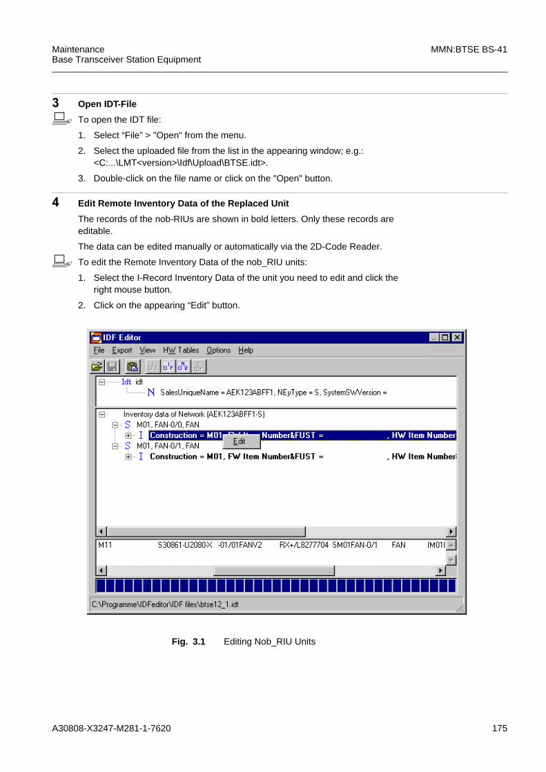
A30808-X3247-M281-1-7620 175
MaintenanceBase Transceiver Station Equipment
MMN:BTSE BS-41
3 Open IDT-File
b To open the IDT file:
1. Select “File” > "Open" from the menu.
2. Select the uploaded file from the list in the appearing window; e.g.:<C:...\LMT<version>\Idf\Upload\BTSE.idt>.
3. Double-click on the file name or click on the "Open" button.
4 Edit Remote Inventory Data of the Replaced Unit
The records of the nob-RIUs are shown in bold letters. Only these records areeditable.
The data can be edited manually or automatically via the 2D-Code Reader.
b To edit the Remote Inventory Data of the nob_RIU units:
1. Select the I-Record Inventory Data of the unit you need to edit and click theright mouse button.
2. Click on the appearing “Edit” button.
Fig. 3.1 Editing Nob_RIU Units
176 A30808-X3247-M281-1-7620
MMN:BTSE BS-41 MaintenanceBase Transceiver Station Equipment
3. Edit the data manually, or click on the “Scan” button to use the 2D-CodeReader.
4. If the 2D-Code Reader is used for the first time, select the serial port in theappearing window.
5. To start the scanning process, press the button on the 2D-Code Reader.
6. The data are inserted into the corresponding fields.Confirm the data byclicking on the “OK” button.
7. Select “File” -> “Save” from the menu.
5 Export Remote Inventory Data for Backup
Now you must create an IDF file for backup. This IDF file replaces the IDF filedelivered with the rack. It contains the modified data of the BTSE.
b To export the Remote Inventory data for backup:
1. Select “Export” > "IDF" from the menu.
2. Select the destination path in the appearing window, preferably “A:\”. The filename is automatically composed of the “SalesUniqueName” with theextension “.idf”.
3. Click on the “Save” button.
4. Put the disk with the backup file of the inventory data to the site specificdocumentation.
6 Export nob_RIU Data
The nob_RIU data must be downloaded to the BTSE. In order to downloadthem, you must export the nob_RIU data again into a NOB file. This new NOBfile now contains all modified data without the redundant nob_RIUs.
b To export the nob_RIU data:
1. Select “Export” -> “NOB” from the menu.
2. A window opens in which you can edit the file name and select the directoryin which the file is saved. By default, the file name is composed of the“SalesUniqueName” with the extension “.nob”. Edit the file name and selectthe source directory or confirm the default name and directory by clicking onthe “Save” button.
3. The nob_RIU data are exported to the NOB file. The selected destinationpath of this file is displayed in an attention window. Confirm by clicking on the“OK” button.
4. A question window is displayed: “Create BTS_NRIU for download?” Confirmby clicking on the “Yes” button. An attention window is displayed that informsyou on the destination path and file name to which the BTS_NRIU downloadis saved. Confirm by clicking on the “OK” button.
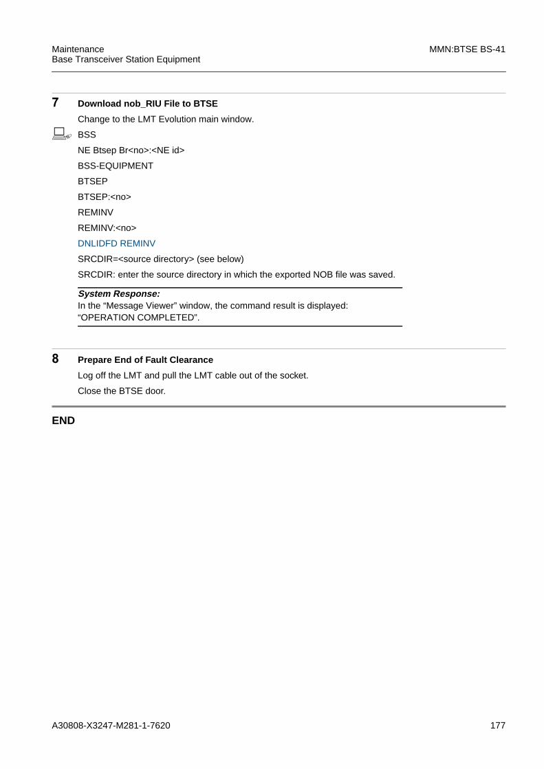
A30808-X3247-M281-1-7620 177
MaintenanceBase Transceiver Station Equipment
MMN:BTSE BS-41
7 Download nob_RIU File to BTSE
Change to the LMT Evolution main window.
b BSS
NE Btsep Br<no>:<NE id>
BSS-EQUIPMENT
BTSEP
BTSEP:<no>
REMINV
REMINV:<no>
DNLIDFD REMINV
SRCDIR=<source directory> (see below)
SRCDIR: enter the source directory in which the exported NOB file was saved.
8 Prepare End of Fault Clearance
Log off the LMT and pull the LMT cable out of the socket.
Close the BTSE door.
END
System Response:In the “Message Viewer” window, the command result is displayed:“OPERATION COMPLETED”.

178 A30808-X3247-M281-1-7620
MMN:BTSE BS-41 MaintenanceBase Transceiver Station Equipment
3.40 TMA
1 Interpret the Fault Message ......(see 5.4)
Note the values specified in the fault message, for example:
– Module(s) ??
– BTS-no ??
– Rack-no ??
– Module address ??
Use these values for command input.
Use the logical address to find the mounting location of the module(s). ......(see 4.3)
2 Interpret the Alarm Type
Is one of the following values listed in the fault message?
– VSWR Alarm
– Cable Problem
– Transceiver Problem
Y h...Procedure:3.41
N h...3
3 Connect the LMT to the BTSE
Plug the LMT cable into the corresponding socket. ......(see Fig. 4.4)
Start LMT Login - Procedure (refer to LMT description).
iModule TMA may be removed while power is on.

A30808-X3247-M281-1-7620 179
MaintenanceBase Transceiver Station Equipment
MMN:BTSE BS-41
4 Lock All Relevant CUs
Relevant CUs are all CUs which are connected over FICOM/DUAMCO /FDUAMCO to an antenna at the same mast of the suspected TMA.
b BSS
NE Btsep Br<no>:<NE id>
BSS-EQUIPMENT
BTSEP
BTSEP:<no>
RACK
RACK:<no>
CU
CU:<no>
LOCK CU
Lock CU:NAME=RACK:<no>/CU:<no> ;
5 Next CU
Is there one relevant CU not yet locked? Y h...4N h...6
System Response:The command is acknowledged (ACK).Several changed state event reports follow. They can be examined in the“Message Viewer” window.

180 A30808-X3247-M281-1-7620
MMN:BTSE BS-41 MaintenanceBase Transceiver Station Equipment
6 Lock suspected module
b BSS
NE Btsep Br<no>:<NE id>
BSS-EQUIPMENT
BTSEP
BTSEP:<no>
RACK
RACK:<no>
TMA
TMA:<no>
LOCK TMA
Lock TMA:NAME=RACK:<no>/TMA:<no> ;
7 Module replacement
1. Disconnect all Coaxial cables, see HW:BTSE Modules, TMA for finding theappropriate module description.
2. Unmount the affected TMA.
3. Select a module with a functional HW / SW state compatible to that of themodule which is being replaced.
4. Mount the TMA.
5. Connect all cables .
6. Check correct connection to BTSE and antenna.
System Response:The command is acknowledged (ACK).Several changed state event reports follow. They can be examined in the“Message Viewer” window.
!The ESD precautions must be taken when pulling and inserting a module.Refer to 1.5 "Module Replacement Instructions".

A30808-X3247-M281-1-7620 181
MaintenanceBase Transceiver Station Equipment
MMN:BTSE BS-41
8 Run Test for Replaced Module
b BSS
NE Btsep Br<no>:<NE id>
BSS-EQUIPMENT
BTSEP
BTSEP:<no>
RACK
RACK:<no>
TMA
TMA:<no>
PERFTEST TMA
NAME=RACK:<no>/TMA<no>
Perftest TMA:NAME=RACK:<no>/ TMA:<no> ;
Is the test outcome as follows?
– Test Outcome = Pass h...9– Test Outcome = Fail h...16
System Response:The command is acknowledged (ACK).
Test Result:The test report can be examined in the “Message Viewer” window. Note the testoutcome.If the test outcome is "fail", some more information is given, such as "ProposedRepair Action" etc.

182 A30808-X3247-M281-1-7620
MMN:BTSE BS-41 MaintenanceBase Transceiver Station Equipment
9 Unlock suspected module
b BSS
NE Btsep Br<no>:<NE id>
BSS-EQUIPMENT
BTSEP
BTSEP:<no>
RACK
RACK:<no>
TMA
TMA:<no>
UNLOCK TMA
Unlock TMA:NAME=RACK:<no>/TMA:<no> ;
10 Unlock All Relevant CUs
b BSS
NE Btsep Br<no>:<NE id>
BSS-EQUIPMENT
BTSEP
BTSEP:<no>
RACK
RACK:<no>
CU
CU:<no>
UNLOCK CU
Unlock CU:NAME=RACK:<no>/CU:<no> ;
11 Next CU
Is there one relevant CU not yet unlocked? Y h...10N h...12
System Response:The command is acknowledged (ACK).Several changed state event reports follow. They can be examined in the“Message Viewer” window.
System Response:The command is acknowledged (ACK).Several changed state event reports follow. They can be examined in the“Message Viewer” window.

A30808-X3247-M281-1-7620 183
MaintenanceBase Transceiver Station Equipment
MMN:BTSE BS-41
12 Check LED PA on all relevant CUs
– The LED PA is not on h...13– The LED PA is red h...16
13 Mark the Replaced Module as Defective
14 Updating of the Remote Inventory Data
For updating the remote inventory data refer to procedure “Remote InventoryData Update” in this manual.
h...Procedure: 3.39
15 End of Fault Clearance Procedure
Log off the LMT and pull the LMT cable out of the socket.
Close the BTSE door.
16 Reinsert the Replaced Module
Remove the currently inserted module and reinsert the old (replaced) modulebecause the old module was probably not defective. Refer to the relevant part inthe replacement procedure.
h...17
17 Next suspected module
Is one of the suspected modules not yet replaced? Y h...18N h...19
18 Replacement Procedure for the Next Suspected Module/Interface
Go to the replacement procedure for the next suspected module/interface. h...Procedure: 3.x
19 Unsuccessful module replacement
Call TAC.
END
Wait a few seconds, until the bootprocess is finished (green LED:OK and SWare flashing), see HW:BTSE Modules, CU for finding the appropriate moduledescription.

184 A30808-X3247-M281-1-7620
MMN:BTSE BS-41 MaintenanceBase Transceiver Station Equipment
3.41 TX/RX Path (e.g. VSWR)
Examples for Alarms in the TX/RX Path
RF power reflected into power stage
Cell 0,1,2: Antenna System TX
FICOM_VSWRP: VSWR alarm Low or High
DUAMCO: RX alarm Low or High
DIAMCO: RX alarm Low or High
TMA: RX alarm Low or High
1 Cable connections fastened correctly?
Are the TX cable connections of the suspected module fastened correctly? Y h...6N h...2
2 Fasten cable connections
Make sure to fasten all cables by tightening their coupling nuts with a torquewrench.
3 Check the LED VSWR or ALARM on the suspected module
Do the LED switch off after a few seconds? Y h...4N h...6
iIn most cases, alarms in the TX/RX path originate from loose or damaged cables.Therefore, the relevant cables must be checked first, according to the following proce-dure.
If the alarm cannot be cleared in this way, the suspected modules must be replaced.Note that the failure cause may be located in any module of the TX/RX path:- the module(s) addressed in the error message- combining equipment- antenna.
It is recommended to start with the replacement of the module which is addressed inthe fault message. Afterwards - if the error is still there - to take the other modules inthe TX/RX path into consideration.
iTo make sure that no calls are lost, check whether the corresponding TRX is shutdown before cables/modules are disconnected. If the TRX is still in use, call the OMCto have it shut down. For more information, refer to 1.5.2 "Avoiding the Loss of Calls".
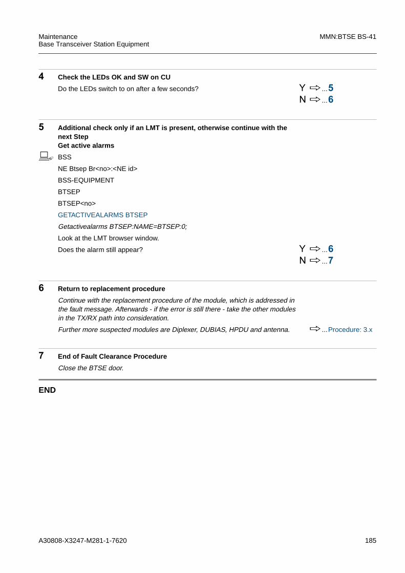
A30808-X3247-M281-1-7620 185
MaintenanceBase Transceiver Station Equipment
MMN:BTSE BS-41
4 Check the LEDs OK and SW on CU
Do the LEDs switch to on after a few seconds? Y h...5N h...6
5 Additional check only if an LMT is present, otherwise continue with thenext StepGet active alarms
b BSS
NE Btsep Br<no>:<NE id>
BSS-EQUIPMENT
BTSEP
BTSEP<no>
GETACTIVEALARMS BTSEP
Getactivealarms BTSEP:NAME=BTSEP:0;
Look at the LMT browser window.
Does the alarm still appear? Y h...6N h...7
6 Return to replacement procedure
Continue with the replacement procedure of the module, which is addressed inthe fault message. Afterwards - if the error is still there - take the other modulesin the TX/RX path into consideration.
Further more suspected modules are Diplexer, DUBIAS, HPDU and antenna. h...Procedure: 3.x
7 End of Fault Clearance Procedure
Close the BTSE door.
END

186 A30808-X3247-M281-1-7620
MMN:BTSE BS-41 MaintenanceBase Transceiver Station Equipment

A30808-X3247-M281-1-7620 187
MaintenanceBase Transceiver Station Equipment
MMN:BTSE BS-41
4 Tables, Lists and Figures

188 A30808-X3247-M281-1-7620
MMN:BTSE BS-41 MaintenanceBase Transceiver Station Equipment

A30808-X3247-M281-1-7620 189
MaintenanceBase Transceiver Station Equipment
MMN:BTSE BS-41
4.1 Hardware Architecture
Fig. 4.1 BS-41

190 A30808-X3247-M281-1-7620
MMN:BTSE BS-41 MaintenanceBase Transceiver Station Equipment
Fig. 4.2 Functional blocks
DUAMCO/
FICOM
DIAMCO
Base Rac k / Shelter
Service Rac k / Shelter
CU 0
CU 3
COBA
COSA
CC
CC
CAN BUS
48 Site Inputs
4 x ABISExt.Sync.2 PCM
2 PCM
4 PCM 4 x ABIS
1 x Ext.Sync. CLK
8 Site Outputs
ACTM
TempAlarms
Door
FAN
ACTC
ACTC
LE 0
ACTP
LE 1
FANDoor
AlarmsTemp
Fan
Battery
CAN-BUS
DCP -48 V
BatteryAC/DC
DCB-CTRL
ACP
DCP-48 V
230(207*)VAC 230(207*)VAC
* In Case of BS-40U
OVPT/ABISCON
optional
OVPT/ABISCON
optional
(not BS-41U)
CELL 0
CELL 0
CELL 1
CELL 1
ANT 0
ANT 1
ANT 0
ANT 1
HPDU
DUBIAS
TMA
TMA
TMA
TMA
TXRXRXDIV
RXRXDIV
TX
RX
RXDIV
FDUAMCO
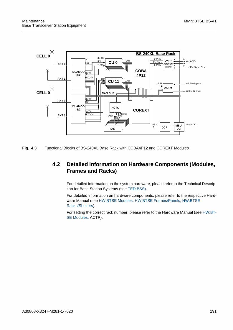
A30808-X3247-M281-1-7620 191
MaintenanceBase Transceiver Station Equipment
MMN:BTSE BS-41
Fig. 4.3 Functional Blocks of BS-240XL Base Rack with COBA4P12 and COREXT Modules
4.2 Detailed Information on Hardware Components (Modules,Frames and Racks)
For detailed information on the system hardware, please refer to the Technical Descrip-tion for Base Station Systems (see TED:BSS).
For detailed information on hardware components, please refer to the respective Hard-ware Manual (see HW:BTSE Modules, HW:BTSE Frames/Panels, HW:BTSERacks/Shelters).
For setting the correct rack number, please refer to the Hardware Manual (see HW:BT-SE Modules, ACTP).
CELL 0
ANT 0
ANT 1
DUAMCO
BS-240XL Base Rac k3x TX
CU 0
CU 11
COBA
COREXT
CC
CC
RXRXDIV
RXRXDIV
3x TX
CAN BUS
48 Site Inputs
4 x ABIS
16 AL
Ext.Sync.2 PCM
2 PCM1 x Ext.Sync. CLK
8 Site Outputs
ACTM
DCP
AlarmsDoor
-48 V
FAN
ACTC
RX
Temp
OVPT/ABISCON
optional
MSUDC
-48 V DC
4P128:2
DUAMCO8:2
RXDIV
3x TX
3x TX
RX
CELL 0
ANT 0
ANT 1 RXDIV

192 A30808-X3247-M281-1-7620
MMN:BTSE BS-41 MaintenanceBase Transceiver Station Equipment
4.3 Front View of the BS-41 Shelter
Fig. 4.4 BS-41 Base Shelter Design and Configuration
ACTP
ACTA optional
LMT
DIA
MC
O0
Battery
FANP 0 FANP 1
FANP 2 FANP 3
FANP 4 FANP 5
DC
BC
TR
L0
AC-Panel
AC/DC#02
AC/DC#01
AC/DC#00
LE#01
LE#00
HPDU#0
HPDU#1
OVPT
DCP
BS-41
Plinth
(F)D
UA
MC
O0
or F
ICO
M0
(F)D
UA
MC
O1
or F
ICO
M1
ACDCP 0 is dependenton the DIP switch setting,see HW:BTSE Modules,DCBCTRL for finding theappropriate moduledescription.
Hardware ManagedObjects (HMO) areshown in Tab. 4.1,Tab. 4.2, Tab. 4.3,and Tab. 4.4.
With core redundancy:The active COBA andCOSA can be the left pairor the right pair. Theactive pair is alwaysCOBA 0 and COSA 0.The redundant pair isCOBA 1 and COSA 1.Independent on themounting position.
CU
1/ F
lexC
U1
CU
0/ F
lexC
U0
CU
3/ F
lexC
U3
CU
2/ F
lexC
U2
CO
BA
0
CO
SA
0C
OB
A1
CO
SA
1

A30808-X3247-M281-1-7620 193
MaintenanceBase Transceiver Station Equipment
MMN:BTSE BS-41
Fig. 4.5 BS-41 Service2 Shelter Design and Configuration (example)
ACTP
LE #5
LE #4
LE #3
LE #2
LE #1
LE #0
FANP 1FANP 0
DCP
OVPT
Battery
Plinth
Battery
Battery
Battery
Battery
Battery
Battery
Battery
BS-41
All Batteries arecreated in Rack 0.

194 A30808-X3247-M281-1-7620
MMN:BTSE BS-41 MaintenanceBase Transceiver Station Equipment
Fig. 4.6 4 Carrier BTSE BS-41
Shelter 0Base Shelter
Shelter 4Service2 Shelter(not BS-41U)
TMA
32
10

A30808-X3247-M281-1-7620 195
MaintenanceBase Transceiver Station Equipment
MMN:BTSE BS-41
4.4 Corresponding Hardware Managed Objects (HMO)
iHMOs with names identical to those of their modules are not explicitly listed.Example: The HMO of the COBA1 is called COBA1, and is not mentioned.
Module Type Module Number Hardware ManagedObjects (HMO)
FlexCU FCU 0 FCUMAIN 0FCUTR 0,1
FCU 1 FCUMAIN 1FCUTR 2,3
FCU 2 FCUMAIN 2FCUTR 4,5
FCU 3 FCUMAIN 3FCUTR 6,7
Tab. 4.1 Possible Modules and their Hardware Managed Objects (HMO) for FlexCU
iCU, GCU, or ECU can also be installed instead of FlexCU.The HMOs are then all called CU0..x.
Module Type Module Number Hardware ManagedObjects (HMO)
(F)DUAMCO (F)DUAMCO 0 DUDCTMA 0,1DULNA 0,1DUVSWR 0,1
(F)DUAMCO 1 DUDCTMA 2,3DULNA 2,3DUVSWR 2,3
FICOM FICOM 0 FTNFP 0,1FVSWRP 0
FICOM 1 FTNFP 2,3FVSWRP 1
Tab. 4.2 Possible Modules and their Hardware Managed Objects (HMO) for ACOM
iThe module COAMCO has no HMOs.

196 A30808-X3247-M281-1-7620
MMN:BTSE BS-41 MaintenanceBase Transceiver Station Equipment
4.5 TX/RX Paths of Some Configuration Examples
This chapter shows diagrams of the TX/RX paths of 3 configuration examples. For eachconfiguration a table is given which lists some details on possible failures, their possibleeffects and how they can be detected.
Failures in the TX/RX paths are detected by one or more failure detection systems/alarmtypes:
Module Type Module Number Hardware ManagedObjects (HMO)
DIAMCO DIAMCO 0 DIDCTMA 0,1DILNA 0,1
Tab. 4.3 Possible Modules and their Hardware Managed Objects (HMO) for MUCO
Module Type Module Number Hardware ManagedObjects (HMO)
DCBCTRL DCBCTRL 0 ACDCP 0
Tab. 4.4 Possible Modules and their Hardware Managed Objects (HMO) forDCBCTRL
iThis chapter provides an overview, but does not claim to provide complete lists of pos-sible errors, their possible effects and detection systems.The actual sets of error messages depend on customer specific conditions such as theindividual configuration of the base station system, customer defined thresholds andfurther details that cannot be taken into account here.The occurrence frequency of the errors is not considered and may differ considerably.
- VSWR MonitoringExamples of corresponding alarms:Combining Equipment:Error ID <no> – DUAMCO: VSWR alarm HIGHError ID <no> – FICOM_VSWRP: VSWR alarm HIGHCU:Error ID <no> – RF power reflected into powerstage
- RX Diversity AlarmsExample:Error ID <no> – One of the two diversity receivers fails
- TNF Monitoring (Filter Combiner)Example of corresponding alarms:Error ID <no> – FICOM_TNFP: TNF tuning alarm
- LNA AlarmsExamples:Error ID <no> – DIAMCO: RX alarm LOWError ID <no> – DIAMCO: RX alarm HIGH

A30808-X3247-M281-1-7620 197
MaintenanceBase Transceiver Station Equipment
MMN:BTSE BS-41
Error ID <no> – DUAMCO: RX alarm LOWError ID <no> – DUAMCO: RX alarm HIGH
- Sleeping Cell DetectionBSC alarm: Transceiver Problem (Specific Problem: No call incell within a predefined time frame)
- Online RF LoopbackError ID <no> – Increased path loss difference

198 A30808-X3247-M281-1-7620
MMN:BTSE BS-41 MaintenanceBase Transceiver Station Equipment
Fig. 4.7 TX/RX Paths of Configuration with FICOM, DIAMCO, HPDU, DUBIAS, TMA
FICOMDUAMCO /FDUAMCO
CU
HPDU
DUBIAS
1
3
8 9
10
12
14
13
15
16
11
2
3
5
7
6
TMA
14
The numbering in the figure refers to the numbering in the corresponding table.
*
TMA
CU11
4 4
Hardware ManagedObjects (HMO) arelisted in Tab. 4.1(FlexCU) andTab. 4.2 (ACOM).
* Configuration withone TX antenna.Note:Configurations withadditional TXantennas for thesame cell are alsopossible.

A30808-X3247-M281-1-7620 199
MaintenanceBase Transceiver Station Equipment
MMN:BTSE BS-41
No. Failure Cause Effect Detected by...
1 TX/RX antenna defect, cable dis-rupted
VSWR Alarm (dependant onattenuation figures);reduced sensitivity;reduced coverage area
VSWR monitoring;Sleeping Cell Detection if theBCCH carrier is affected (theBCCH carrier is always affected ifonly one TX antenna is used);Online RF Loopback;RX diversity alarm
2 TX/RX antenna out of bearing(e.g. after windstorms)
reduced coverage area;coverage area reduced to zero;no real on air combining (reduceddiversity gain; high drop call ratein case of handover to alternateantenna; reduced cell capacity);VSWR alarm
Online RF Loopback;Sleeping Cell Detection if theBCCH carrier is affected (theBCCH carrier is always affected ifonly one TX antenna is used);VSWR monitoring
3 RF feeder cable poorly assem-bled or disrupted
TX/RX cable: reduced coveragearea for affected antenna;VSWR Alarm;RX cable: reduced diversity gain;
Online RF Loopback;VSWR monitoring;RX Diversity Alarm;
4 RF-RX path interruption insideTMA
reduced diversity gain TMA Alarm;Online RF Loopback;RX Diversity Alarm
5 RF cable damaged betweenDUBIAS and HPDU
VSWR Alarm;reduced coverage area;reduced diversity gain;
VSWR monitoring;Online RF Loopback;RX Diversity Alarm
6 RF cable damaged betweenDUBIAS and DIAMCO
reduced diversity gain Online RF Loopback;RX Diversity Alarm;TMA Alarm
7 RF cable damaged betweenHPDU and FICOM
VSWR Alarm;reduced coverage area;
VSWR monitoring;Online RF Loopback;
8 FICOM: mistuned TNF operation and maintenance SWdisables carrier due to FICOMred tuning alarm
TNF monitoring
9 RF path interruption insideFICOM
coverage area reduced to zerofor carriers behind interruptionpoint
Online RF Loopback;Sleeping Cell Detection if theBCCH carrier is affected (theBCCH carrier is always affected ifonly one TX antenna is used)
10 RF cable damaged betweenFICOM and CU (HPA)
SW disables carrier due to VSWRAlarm
VSWR monitoring of HPA/CU;Online RF Loopback if VSWRmonitoring fails (if BasebandHopping is activated a thresholdmust be exceeded)
Tab. 4.5 Failure Causes in the TX/RX Path, Configuration with FICOM, DIAMCO, HPDU, DUBIAS, TMA

200 A30808-X3247-M281-1-7620
MMN:BTSE BS-41 MaintenanceBase Transceiver Station Equipment
11 Failure inside CU (HPA) (isolatornot properly soldered)
SW disables CU due to VSWRAlarm
VSWR monitoring;Online RF Loopback is possible ifVSWR monitoring fails (if Base-band Hopping is activated athreshold must be exceeded)
12 RX antenna defect, cable disrupt-ed
reduced sensitivity RX Diversity Alarm
13 RX antenna out of bearing reduced RX sensitivity;no RX signal
RX Diversity Alarm
14 RX feeder cable poorly assem-bled or disrupted
reduced sensitivity due to the lossof one RX branch
RX Diversity Alarm
15 RF path interruption insideDIAMCO
reduced sensitivity due to the lossof one RX branch
LNA Alarm;RX Diversity Alarm;Online RF Loopback
16 RF cable damaged betweenDIAMCO and CU
reduced sensitivity due to the lossof one RX branch
RX Diversity Alarm
No. Failure Cause Effect Detected by...
Tab. 4.5 Failure Causes in the TX/RX Path, Configuration with FICOM, DIAMCO, HPDU, DUBIAS, TMA

A30808-X3247-M281-1-7620 201
MaintenanceBase Transceiver Station Equipment
MMN:BTSE BS-41
Fig. 4.8 TX/RX Paths of Configuration with DUAMCO / FDUAMCO
1
3
5
2
CU6
The numbering in the figure refers to the numbering in the corresponding table.
CU6
DUAMCO /FDUAMCO
4
Hardware ManagedObjects (HMO) arelisted in Tab. 4.1(FlexCU) andTab. 4.2 (ACOM).

202 A30808-X3247-M281-1-7620
MMN:BTSE BS-41 MaintenanceBase Transceiver Station Equipment
No. Failure Cause Effect Detected by...
1 TX/RX antenna defect, cable dis-rupted
VSWR Alarm (dependant on at-tenuation figures);reduced sensitivity;reduced coverage area
VSWR monitoring;Sleeping Cell Detection if theBCCH carrier is affected (theBCCH carrier is always affected ifonly one TX antenna is used);Online RF Loopback;RX diversity alarm
2 TX/RX antenna out of bearing(e.g. after windstorms)
reduced coverage area;coverage area reduced to zero;no real on air combining (reduceddiversity gain; high drop call ratein case of handover to alternateantenna; reduced cell capacity);VSWR alarm
Online RF Loopback;Sleeping Cell Detection if theBCCH carrier is affected (theBCCH carrier is always affected ifonly one TX antenna is used);VSWR monitoring
3 RF feeder cable poorly assem-bled or disrupted
TX/RX cable: reduced coveragearea for affected antenna;VSWR Alarm;RX cable: reduced diversity gain;
Online RF Loopback;VSWR monitoring;RX Diversity Alarm;
4 RF-TX path interruption insideDUAMCO / FDUAMCO;
RF-RX path interruption insideDUAMCO / FDUAMCO
coverage area reduced to zerofor all carriers behind interruptionpoint;reduced signal sensitivity due tothe loss of diversity;
Online RF Loopback;Sleeping Cell Detection if theBCCH carrier is affected (theBCCH carrier is always affected ifonly one TX antenna is used);RX Diversity Alarm
5 RF-TX path interruption betweenDUAMCO / FDUAMCO and CU;
RF-RX path interruption betweenDUAMCO / FDUAMCO and CU
SW disables carrier due to VSWRAlarm
VSWR monitoring of HPA/CU;Online RF Loopback if VSWRmonitoring fails (possibleexception if Baseband Hopping isactivated);RX Diversity Alarm
6 Failure inside CU (HPA) (isolatornot properly soldered)
SW disables CU due to VSWRAlarm
VSWR monitoringOnline RF Loopback if VSWRmonitoring fails (possibleexception if Baseband Hopping isactivated)
Tab. 4.6 Failure Causes in the TX/RX Path, Configuration with DUAMCO / FDUAMCO

A30808-X3247-M281-1-7620 203
MaintenanceBase Transceiver Station Equipment
MMN:BTSE BS-41
Fig. 4.9 TX/RX Paths of Configuration with DIPLEXER
DIPLEXER
1 2
3
4 5
FICOMDUAMCO /FDUAMCO
CU CU CU CU
The numbering in the figure refers to the numbering in the corresponding table.
See Configuration Examplewith DUAMCO / FDUAMCO
See Configuration Examplewith FICOM etc.
Hardware ManagedObjects (HMO) arelisted in Tab. 4.1(FlexCU) andTab. 4.2 (ACOM).

204 A30808-X3247-M281-1-7620
MMN:BTSE BS-41 MaintenanceBase Transceiver Station Equipment
No. Failure Cause Effect Detected by...
1 TX/RX antenna defect, cable dis-rupted
VSWR Alarm (dependant onattenuation figures);reduced sensitivity;reduced coverage area
VSWR monitoring;Sleeping Cell Detection if theBCCH carrier is affected (theBCCH carrier is always affected ifonly one TX antenna is used);Online RF Loopback;RX diversity alarm
2 TX/RX antenna out of bearing(e.g. after windstorms)
reduced coverage area;coverage area reduced to zero;no real on air combining (reduceddiversity gain; high drop call ratein case of handover to alternateantenna; reduced cell capacity);VSWR alarm
Online RF Loopback;Sleeping Cell Detection if theBCCH carrier is affected (theBCCH carrier is always affected ifonly one TX antenna is used);VSWR monitoring
3 RF feeder cable poorly assem-bled or disrupted
TX/RX cable: reduced coveragearea for affected antenna;VSWR Alarm;RX cable: reduced diversity gain;
Online RF Loopback;VSWR monitoring;RX Diversity Alarm;
4 RF cable damaged betweenDIPLEXER and FICOM
VSWR Alarm;reduced coverage area;coverage area reduced to zero
VSWR monitoring;Online RF Loopback;Sleeping Cell Detection if theBCCH carrier is affected (theBCCH carrier is always affected ifonly one TX antenna is used)
5 RF cable damaged betweenDIPLEXER and DUAMCO /FDUAMCO
VSWR Alarmreduced coverage area;coverage area reduced to zero;reduced diversity gain
VSWR monitoring;Online RF Loopback;Sleeping Cell Detection if theBCCH carrier is affected (theBCCH carrier is always affected ifonly one TX antenna is used);RX Diversity Alarm
Tab. 4.7 Failure Causes in the TX/RX Path, Configuration with DUAMCO / FDUAMCO, FICOM, DIPLEXER
A30808-X3247-M281-1-7620 205
MaintenanceBase Transceiver Station Equipment
MMN:BTSE BS-41
5 Appendix
5.1 HW/SW Compatibility During Download from LMT/BSC
This feature allows a compatibility check of the swLoad and the current HW situation ofthe BTSE, there by preventing a download of a swLoad which will not run on the specificBTSE.
This check is done by means of a compatibility matrix - the Version Attachment Mecha-nism (VAM) file which is the second file of the swLoad. The check is carried out whenthis VAM file is received in the BTSE. On negative result the further download of theswImages is stopped.
This check is only available in the load phase.
swLoad : GSM notation for a complete SW package containing all the load SW of a net-work element.
swImage : GSM notation for the load SW package for a single module inside a networkelement.
VAM file : represents the context between the swImages and the HW-SW compatibility.
Test Report in Case of a Failed VAM Check:
JOB: <no>PC Time&Date: <time> <date>NE Time&Date: <time> <date>USER: <user>SW RELEASE: <no>COMMAND RESULT: <command result>
Test Report:
name = BTSETEST:<no>testOutcome = <fail or aborted>testTermination = <normal or aborted>MOT = RACK:<no>/<Module>:<no>executedPhases
(...)
Proposed Repair Action(...)
Other Information = H’01 H’00 H’00 H’00 H’00 H’00 H’00 H’00
END OF OUTPUT FOR JOB <no>

206 A30808-X3247-M281-1-7620
MMN:BTSE BS-41 MaintenanceBase Transceiver Station Equipment
Meaning of Other Information:
All other bytes are not used.
If the first byte of the string “Other Information” is H’01, the result of the VAM check isnegative. In this case, it has to be checked whether the HW version of the replaced mod-ule is supported by the actual SW version according to the stock list/release note. If theHW version is not supported, the module must be replaced by one with a supported HWversion.
5.2 State/Status Attributes of BTSE Managed Objects
The following state/status attributes are used for BTSE MOs:
Other Information = H’01 H’00 H’00 H’00 H’00 H’00 H’00 H’00⇑01 VAM check failed02 board recovery (2x PROC_ID)03 no startup04 board failed05 board deleted06 board power off
State/Status Attribute State/Status Explanation
Administrative State(AST)
This state informs whether or not the MO is permitted to provideservice.
Locked The related MO is not permitted to provide service, but is addres-sable for maintenance tasks and fully operable (it can, for exam-ple, be tested). This state can be brought about via the LMT“Lock” command.Note: at the BTSE, only HMOs can be locked/unlocked.
Shutting Down The MO is currently shutting down, i.e. ongoing calls are not in-terrupted, but no new calls are permitted.This state cannot be brought about via LMT at the BTSE.
Unlocked Service is permitted.This state can be brought about via the LMT “Unlock” command.Note: at the BTSE, only HMOs can be locked/unlocked.
Operational State(OST)
This state informs whether or not the MO is able to provide ser-vice.
Enabled (ena) The MO is able to provide service.(Exception: The MOs “RACK”, “BTSE” and “ENVABTSE” arealways “Enabled”, even if, for example, a service rack is notinstalled.)
Disabled (dis) The MO is not able to provide service.
Tab. 5.1 State/Status Attributes of BTSE MOs

A30808-X3247-M281-1-7620 207
MaintenanceBase Transceiver Station Equipment
MMN:BTSE BS-41
Alarm Status (ALS) This status reports the severity level of active alarms. If morethan one alarm is active, the level of the alarm with the highestseverity level is reported.
Critical At least one active alarm with severity level “critical”(see 5.3.3.1).
Major At least one active alarm with severity level “major” (see 5.3.3.2).
Minor At least one active alarm with severity level “minor” (see 5.3.3.3).
Cleared No active alarms.
Availability Status This status reports details on AST or OST.
In Test (tst) Intrusive test under progress.
Failed (fail) MO is defective/not operable.
Power Off (pof) The power of the MO is switched off.
Degraded (deg) The service is degraded.
Off Line (ofl) The creation of the MO is in progress.
Dependency (Dep) The MO cannot operate because of another MO on which it de-pends.
Not Installed (noi) The MO is not installed.
Null Value (nul) Value after the creation of an MO (+Disabled/Locked).Certain processes still in progress (e.g. alignment).MO TRX: transient failure of a HMO.
Procedural Status(PRS)
This status reports whether or not the MO performs an initializa-tion procedure.
Initialising (ini) Initialization is in progress.
Null Value (nul) No initialization
Standby Status (STS) This status reports information on redundant MOs.
Null This value is used in combination with OST “Disabled”.
Providing Service This value is used in combination with OST “Enabled”/AST “Un-locked”. The MO provides service.
Cold Standby The MO is able to provide service but it is either not active or it islocked.
State/Status Attribute State/Status Explanation
Tab. 5.1 State/Status Attributes of BTSE MOs

208 A30808-X3247-M281-1-7620
MMN:BTSE BS-41 MaintenanceBase Transceiver Station Equipment
5.3 BTSE Alarm Information
The following information is forwarded from the BTSE to the BSC :
1. Managed object class
2. Managed object instance
3. Error information
– probable cause value
– event type
– perceived severity
– trend indication
– immediate defense action
– threshold information
– proposed repair action
– error description
– additional information
5.3.1 Probable Cause Value
Probable cause of the fault or error. The probable cause is taken out of a predefined setof values, defined for each event type.
5.3.2 Event Types
Errors are classified in the following categories (so called “event types”):
5.3.2.1 Equipment Errors– detected by hardware check or application software
5.3.2.2 Processing Errors– detected by online software checks and audits
5.3.2.3 Communication Errors– detected by protocols
5.3.2.4 Quality of Service ErrorsThey depend on:
– traffic overload conditions
– excessive instability of the hardware
– loss of hardware components

A30808-X3247-M281-1-7620 209
MaintenanceBase Transceiver Station Equipment
MMN:BTSE BS-41
5.3.2.5 Environmental ErrorsThese errors depend on environmental conditions e.g. temperature, door open orsmoke.
In general, these faults are signalled to the ACT module.
5.3.3 Perceived Severity
The severity level indicates to what extent the functionality of the BTSE is affected. Thefollowing values are used:
5.3.3.1 CriticalThe critical severity level indicates that a service affecting condition has occurred andan immediate corrective action is required. Such a severity can be reported, for exam-ple, if an equipment related managed object MO breaks down completely.
5.3.3.2 MajorThe major severity level indicates that a service affecting condition has developed andan urgent corrective action is required. Such a severity can be reported for example, ifthere is a severe degradation in the capability of the equipment related managed object(MO).
5.3.3.3 MinorThe minor severity level indicates the existence of a non-service affecting fault conditionand that corrective action should be taken in order to prevent a more serious (for exam-ple, service affecting) fault. Such a severity can be reported, for example, when the de-tected alarm condition is not currently degrading the capacity of the equipment relatedmanaged objects (MO).
5.3.3.4 WarningThe warning severity level indicates the detection of a potential or impending service af-fecting fault, before any significant effects have been detected. Actions should be takento further diagnose (if necessary) and correct the problem in order to prevent it from be-coming a fault causing more severe interference to services.
5.3.4 Trend Indication
This parameter specifies the current severity trend of the equipment related managedobject.
5.3.5 Immediate Defense Action
The immediate defense action is performed by the BTSE software to try and solve theproblem. If there is no corresponding defense action, NA is reported.

210 A30808-X3247-M281-1-7620
MMN:BTSE BS-41 MaintenanceBase Transceiver Station Equipment
5.3.6 Threshold Information
5.3.7 Proposed Repair Action
Suggested repair actions. Consult also the corresponding user manual.
5.3.8 Error Description
Detailed description of the error and its probable cause.
5.3.9 Additional Information
A fixed length buffer contains additional information concerning the detected fault/error.This information depends on the error.
5.4 Fault Messages
5.4.1 Fault Messages at the Radio Commander
Fig. 5.1 Fault Messages at the Radio Commander
Actual value: lower threshold (if any)upper threshold (if any)

A30808-X3247-M281-1-7620 211
MaintenanceBase Transceiver Station Equipment
MMN:BTSE BS-41
5.4.2 Fault Messages at the LMT
JOB: <no>
PC Time&Date:<Time> <Date>
NE Time&Date:<Time> <Date>
USER: <Name>
SW RELEASE: <Release>
COMMAND RESULT: Operation successful
FAILURE EVENT REPORT:
NAME = <modul>:<no>
Event Type = Communication Failure Event
Event Time = <Time> <Date>
Probable Cause = Transmitter Error
Specivic Problems = 10270 - Loss of signal
Severity = Major
Trend Indication = More Severe
Notification Identifier = 322
Proposed Repair Actions_1 = 185 - Collect infor for assistance
Proposed Repair Actions_2 = 181 - Test the addressed card
Originator = 1281
Additional Words =
Octets 01 to 16: H’6d63 H’6e61, H’6c72, H’6d66 H’0746 H’0106 H’1a19
Octets 17 to 30: H'ffff H'ffff H'ffff H'ffff H'ffff
Software Version = <Version>
END OF OUTPUT FOR JOB <no>
5.5 BTSE Components
5.5.1 BTSE Components Overview
For a system overview of all BTSE components (modules, frames, racks and managedobjects), refer to chapter 4 "Tables, Lists and Figures"
5.5.2 Numbering of BTSE Components
5.5.2.1 General Rules
Relative Numbering
In general the relative numbering (in the meaning of logical numbering) of the units startswith the figure zero (0). That means the first of a set of devices, modules or racks / shel-ters gets the number 0, the next one the number 1 in sequence, etc.
With the exception of Abis-lines. The numbering starts with 1, 2, 3 ...

212 A30808-X3247-M281-1-7620
MMN:BTSE BS-41 MaintenanceBase Transceiver Station Equipment
5.5.2.2 Specific Rules
Shelter Numbering
The first shelter in a BS-41 is called Base Shelter, and gets the number 0. Altogether,beside one Base Shelter a maximum of 4 Service Shelters can be installed for one BS-41 (not BS-41U).
The rule for numbering of the shelters is shown in the table below. Note, that the num-bering of the Service Shelters always begins with the number 4.
Slot Numbering inside the Shelters
In a shelter slot numbers are defined for accommodation of CUs, ACOMs and MUCOs.There are 4 CU slots (0...3), 2 ACOM slots (0,1) and 1 MUCO slots (0). Additionally inthe Base Shelter 4 CORE slots are defined for housing the core units and their redun-dant ones.
The HPDU 0 is located at the left side of the shelter and the HPDU 1 is located at theright side of the shelter.
The Figure Fig. 4.6 shows as an example the arrangement of a BS-41 with Base Shelter(Shelter 0), 1 Service Shelter (Shelter 4).
5.5.3 Remote Inventory Data
The function “Remote Inventory” of the Siemens Basestation System performs electron-ic, non volatile storing of the complete, individual product identification data (PID) ofeach inventory object.
Modules that have their inventory data on board are called ob_RIUs (on-board RemoteInventory Units). The PID of these ob_RIUs is automatically loaded to the inventory datafile (IDF).
In order to include inventory data of objects without a non volatile storage (e. g. frames,racks, OEM components), the data of these so called nob_RIUs (not on-board RemoteInventory Units) are entered into an inventory data table (IDT) via the LMT and the offlinetool “IDF editor”. These data is stored on the COBA as a nob_RIU file (NOB). Supple-mented with a footer and header, the IDT can be exported and stored as an inventorydata file (IDF) for backup purposes.
In case of the replacement of a nob_RIU component, the NOB file must be updatedmanually and the backup IDF-file with the inventory data, which is stored on site, mustbe updated as well.
In case of a COBA replacement, the inventory data that was stored on the removedCOBA must be rebuilt. This can be done by using the backup IDF-file.
For ob-RIU replacements the inventory data file will be updated automatically.
Shelter numbering Type of Shelter
0 Base Shelter
4...7 Service2 Shelter with Link Equipment and /or Backup Batteries(not BS-41U)
Tab. 5.2 Shelter Numbering
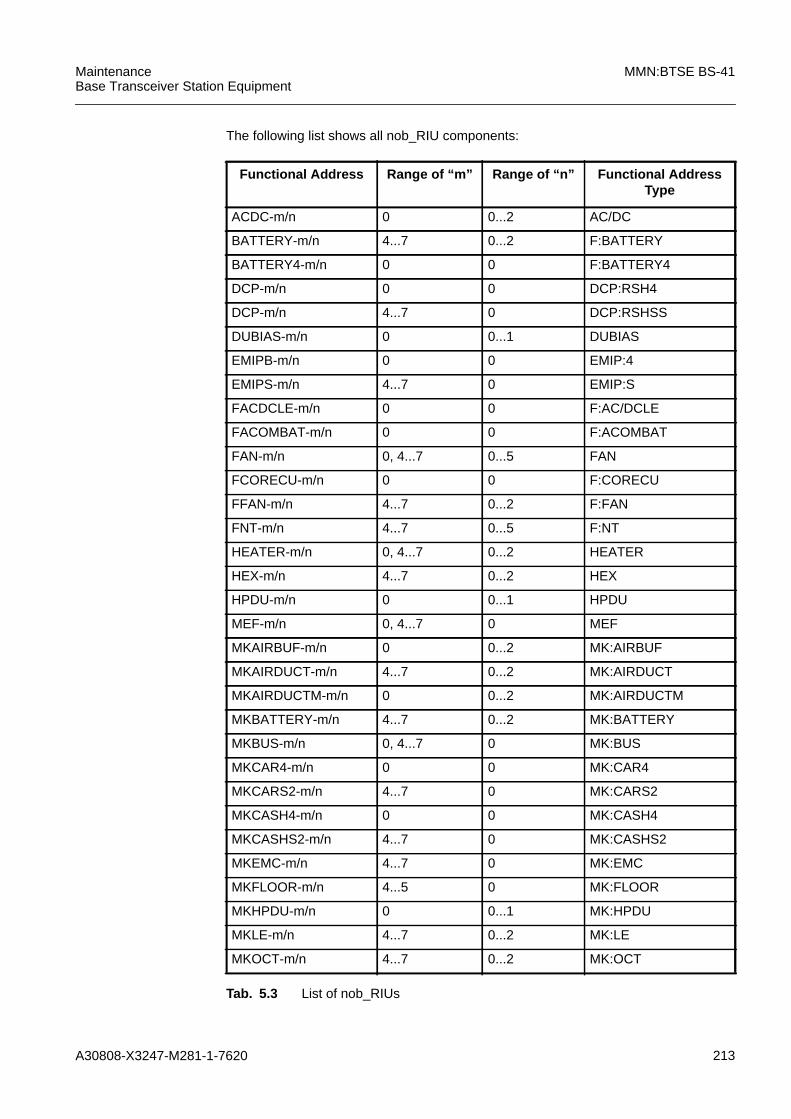
A30808-X3247-M281-1-7620 213
MaintenanceBase Transceiver Station Equipment
MMN:BTSE BS-41
The following list shows all nob_RIU components:
Functional Address Range of “m” Range of “n” Functional AddressType
ACDC-m/n 0 0...2 AC/DC
BATTERY-m/n 4...7 0...2 F:BATTERY
BATTERY4-m/n 0 0 F:BATTERY4
DCP-m/n 0 0 DCP:RSH4
DCP-m/n 4...7 0 DCP:RSHSS
DUBIAS-m/n 0 0...1 DUBIAS
EMIPB-m/n 0 0 EMIP:4
EMIPS-m/n 4...7 0 EMIP:S
FACDCLE-m/n 0 0 F:AC/DCLE
FACOMBAT-m/n 0 0 F:ACOMBAT
FAN-m/n 0, 4...7 0...5 FAN
FCORECU-m/n 0 0 F:CORECU
FFAN-m/n 4...7 0...2 F:FAN
FNT-m/n 4...7 0...5 F:NT
HEATER-m/n 0, 4...7 0...2 HEATER
HEX-m/n 4...7 0...2 HEX
HPDU-m/n 0 0...1 HPDU
MEF-m/n 0, 4...7 0 MEF
MKAIRBUF-m/n 0 0...2 MK:AIRBUF
MKAIRDUCT-m/n 4...7 0...2 MK:AIRDUCT
MKAIRDUCTM-m/n 0 0...2 MK:AIRDUCTM
MKBATTERY-m/n 4...7 0...2 MK:BATTERY
MKBUS-m/n 0, 4...7 0 MK:BUS
MKCAR4-m/n 0 0 MK:CAR4
MKCARS2-m/n 4...7 0 MK:CARS2
MKCASH4-m/n 0 0 MK:CASH4
MKCASHS2-m/n 4...7 0 MK:CASHS2
MKEMC-m/n 4...7 0 MK:EMC
MKFLOOR-m/n 4...5 0 MK:FLOOR
MKHPDU-m/n 0 0...1 MK:HPDU
MKLE-m/n 4...7 0...2 MK:LE
MKOCT-m/n 4...7 0...2 MK:OCT
Tab. 5.3 List of nob_RIUs
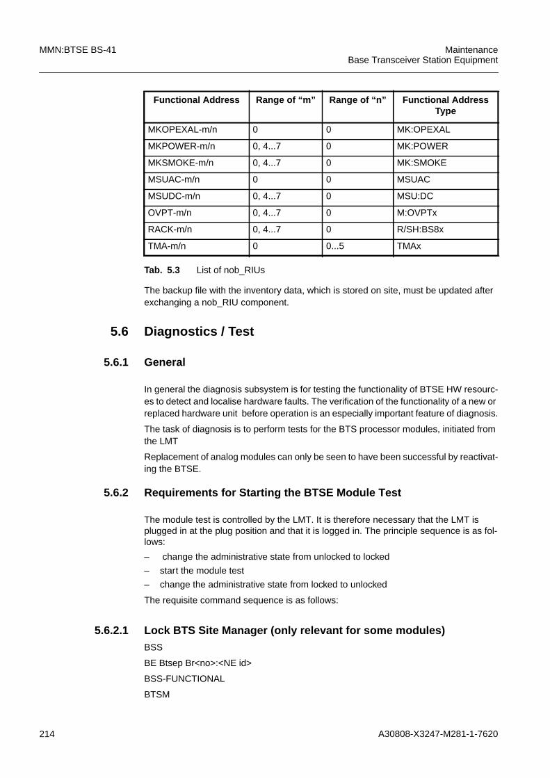
214 A30808-X3247-M281-1-7620
MMN:BTSE BS-41 MaintenanceBase Transceiver Station Equipment
The backup file with the inventory data, which is stored on site, must be updated afterexchanging a nob_RIU component.
5.6 Diagnostics / Test
5.6.1 General
In general the diagnosis subsystem is for testing the functionality of BTSE HW resourc-es to detect and localise hardware faults. The verification of the functionality of a new orreplaced hardware unit before operation is an especially important feature of diagnosis.
The task of diagnosis is to perform tests for the BTS processor modules, initiated fromthe LMT
Replacement of analog modules can only be seen to have been successful by reactivat-ing the BTSE.
5.6.2 Requirements for Starting the BTSE Module Test
The module test is controlled by the LMT. It is therefore necessary that the LMT isplugged in at the plug position and that it is logged in. The principle sequence is as fol-lows:
– change the administrative state from unlocked to locked
– start the module test
– change the administrative state from locked to unlocked
The requisite command sequence is as follows:
5.6.2.1 Lock BTS Site Manager (only relevant for some modules)BSS
BE Btsep Br<no>:<NE id>
BSS-FUNCTIONAL
BTSM
MKOPEXAL-m/n 0 0 MK:OPEXAL
MKPOWER-m/n 0, 4...7 0 MK:POWER
MKSMOKE-m/n 0, 4...7 0 MK:SMOKE
MSUAC-m/n 0 0 MSUAC
MSUDC-m/n 0, 4...7 0 MSU:DC
OVPT-m/n 0, 4...7 0 M:OVPTx
RACK-m/n 0, 4...7 0 R/SH:BS8x
TMA-m/n 0 0...5 TMAx
Functional Address Range of “m” Range of “n” Functional AddressType
Tab. 5.3 List of nob_RIUs

A30808-X3247-M281-1-7620 215
MaintenanceBase Transceiver Station Equipment
MMN:BTSE BS-41
BTSM<no>
LOCKREQUEST BTSM
NAME=BTSM:0
LOCKREQUEST BTSM:NAME=BTSM:0;
5.6.2.2 Change BTSE from Phase 3 to Phase 2 (only relevant for somemodules)BSS
BE Btsep Br<no>:<NE id>
BSS-FUNCTIONAL
BTSM
BTSM<no>
DISCBSC BTSM
NAME=BTSM:0
DISCBSC BTSM:NAME=BTSM:0;
5.6.2.3 Lock Suspected Module (all modules)BSS
BE Btsep Br<no>:<NE id>
BSS-EQUIPMENT
BTSEP
BTSEP<no>
RACK
RACK<no>
<module>
<module><no>
LOCK <module>
LOCK <module>:NAME=RACK:<no>/<module>:<no>;
5.6.2.4 Run Test for Replaced ModuleBSS
BE Btsep Br<no>:<NE id>
BSS-EQUIPMENT
BTSEP
BTSEP<no>
RACK
RACK<no>
<module>
<module><no>

216 A30808-X3247-M281-1-7620
MMN:BTSE BS-41 MaintenanceBase Transceiver Station Equipment
PERFTEST <module>
PERFTEST <module>:NAME=RACK:<no>/<module>:<no>;
Explanation of the test parameters:
Refer to the manual CML:BS-4x/240/241/240XL.
System Response
Example for Test Report
Perftest <MO>:NAME=RACK:<no>/ <MO>:<no>;<date> <time> Command============================================JOB: <no>PC Time&Date = <time> <date>NE Time&Date = <time> <date>USER NAME: <user>COMMAND: Perftest <MO>:NAME=RACK:<no>/ <MO>:<no>;SW RELEASE: = <no>COMMAND RESULT: OPERATION COMPLETED
PERFTEST ACK BTSEP :
name = BTSEP:<no>MOT = RACK:<no>/<MO>:<no>t0 = BTSETEST: <no>
END OF OUTPUT FOR JOB <no>
JOB: <no>PC Time&Date = <time> <date>NE Time&Date = <time> <date>USER NAME: <user>SW RELEASE: <no>COMMAND RESULT: <command result>
Test Report:
name = BTSETEST:<no>test Outcome = <test outcome> (see below)testTermination = NormalMOT = RACK:<no>/<MO>:<no>executedPhases
phaseId = PreliminaryTests<MO>phaseId = CheckAlarmStatus<MO>phaseId = EndTest<MO>
END OF OUTPUT FOR JOB <no>
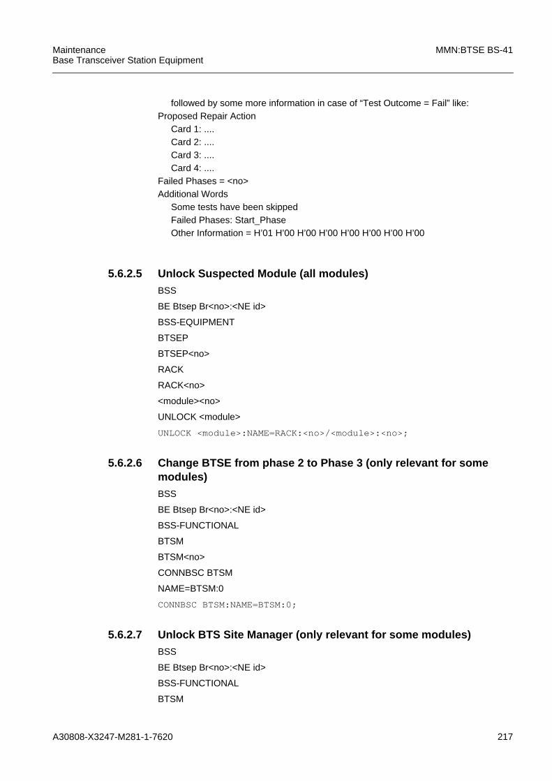
A30808-X3247-M281-1-7620 217
MaintenanceBase Transceiver Station Equipment
MMN:BTSE BS-41
5.6.2.5 Unlock Suspected Module (all modules)BSS
BE Btsep Br<no>:<NE id>
BSS-EQUIPMENT
BTSEP
BTSEP<no>
RACK
RACK<no>
<module><no>
UNLOCK <module>
UNLOCK <module>:NAME=RACK:<no>/<module>:<no>;
5.6.2.6 Change BTSE from phase 2 to Phase 3 (only relevant for somemodules)BSS
BE Btsep Br<no>:<NE id>
BSS-FUNCTIONAL
BTSM
BTSM<no>
CONNBSC BTSM
NAME=BTSM:0
CONNBSC BTSM:NAME=BTSM:0;
5.6.2.7 Unlock BTS Site Manager (only relevant for some modules)BSS
BE Btsep Br<no>:<NE id>
BSS-FUNCTIONAL
BTSM
followed by some more information in case of “Test Outcome = Fail” like:Proposed Repair Action
Card 1: ....Card 2: ....Card 3: ....Card 4: ....
Failed Phases = <no>Additional Words
Some tests have been skippedFailed Phases: Start_PhaseOther Information = H’01 H’00 H’00 H’00 H’00 H’00 H’00 H’00

218 A30808-X3247-M281-1-7620
MMN:BTSE BS-41 MaintenanceBase Transceiver Station Equipment
BTSM<no>
UNLOCKREQUEST BTSM
NAME=BTSM:0
UNLOCKREQUEST BTSM:NAME=BTSM:0;

A30808-X3247-M281-1-7620 219
MaintenanceBase Transceiver Station Equipment
MMN:BTSE BS-41
6 AbbreviationsABISCON Abis Connector Board
AC/DC AC/DC Converter
ACOM Antenna Combiner
ACT Alarm Collection Terminal
ACTA ACT Alarm Board
ACTC ACT Connection Board
ACTM ACT for the Base Rack/Shelter
ACTP ACT Processor Board
ADP AC/DC Panel
BSC Base Station Controller
BSS Base Station System
BTS Base Transceiver Station
BTSE Base Transceiver Station Equipment
CAN Controller Area Network
COBA Core Basis , , ,COSA Core Satellite
CSU Channel Service Unit
CU Carrier Unit
DIAMCO Dual Integrated Amplifier Multicoupler
DUAMCO Duplexer Amplifier Multicoupler
DUBIAS Duplexer Bias Path
ECU EDGE Carrier Unit
ECU EDGE CU
EDGE Enhanced Data Rates for GSM Evolution ,EMI Electromagnetic Interference
ESD Electrostatically Sensitive Device
FAN Fan Unit
FDUAMCO Flexible DUAMCO
FICOM Filter Combiner
GCU GMSK CU
GMSK Gaussian Minimum Shift Keying
GSM Global System for Mobile Communication
HEX Heat Exchanger
HMO Hardware Related Managed Object
HPDU High Power Duplexer
HW Hardware
IDF Inventory Data File
IDT Inventory Data Table
ITMN Installation Test Manual
LAPD Link Access Protocol for D-channel

220 A30808-X3247-M281-1-7620
MMN:BTSE BS-41 MaintenanceBase Transceiver Station Equipment
LED Light Emitting Diode
LMT Local Maintenance Terminal
MEF Membrane Filter
MO Managed Object (e.g. functional part of a module)
MOT Managed Object Under Test
N No
no Number
NOB nob_RIUs only
nob_RIU not on-board Remote Inventory Data
NT Network Termination
ob_RIU on-board Remote Inventory Data
OMC Operation and Maintenance Center
OS Operating System
OVPT Overvoltage Protection and Tracer
PID Product Identification Data
RC Radio Commander
SBS Siemens Base Station
TAC Technical Assistance Center
TMA Tower Mounted Amplifier
VAM Version Attachment Mechanism
VSWR Voltage Standing Wave Ratio
Y Yes

A30808-X3247-M281-1-7620 221
MaintenanceBase Transceiver Station Equipment
MMN:BTSE BS-41
7 IndexAAutorecovery 18
Ccode key 17compatibility 205configuration 192–194CORE Redundancy 43, 53, 63, 73
EEAUTOREC 18
FFault and Test Management 12
Llevers 16Local Fault Clearance 12
NNumbering
Rack / Shelter 194, 212Relative 211Slot 212
RRadio Commander 12
SSpanner 16
TTAC 13tools 16
Wwrist strap 14

222 A30808-X3247-M281-1-7620
MMN:BTSE BS-41 MaintenanceBase Transceiver Station Equipment


