brushless DC motor
59
Controlling a Brushless DC Motor in a Shift-by-Wire System Master’s thesis performed in Vehicular Systems by Johan Wiberg Reg nr: LiTH-ISY-EX-3517-2003 16th December 2003
Transcript of brushless DC motor

Controlling a Brushless DC Motor in aShift-by-Wire System
Master’s thesisperformed in Vehicular Systems
byJohan Wiberg
Reg nr: LiTH-ISY-EX-3517-2003
16th December 2003

Controlling a Brushless DC Motor in aShift-by-Wire System
Master’s thesis
performed at theDivision of Vehicular Systems,Dept. of Electrical Engineering
at Linkopings universitet
for DaimlerChrysler AG
byJohan Wiberg
Reg. No. LiTH-ISY-EX-3517-2003
Supervisors: Michel WillemsDaimlerChrysler AG
Per AnderssonLinkopings universitet
Examiner: Professor Lars NielsenLinkopings universitet
Linkoping, 16th December 2003


Avdelning, InstitutionDivision, Department
DatumDate
Sprak
Language
Svenska/Swedish
Engelska/English
RapporttypReport category
Licentiatavhandling
Examensarbete
C-uppsats
D-uppsats
Ovrig rapport
URL for elektronisk version
ISBN
ISRN
Serietitel och serienummerTitle of series, numbering
ISSN
Titel
Title
ForfattareAuthor
SammanfattningAbstract
NyckelordKeywords
Shift-by-Wire is about replacing the mechanical link between theautomatic transmission and the shift lever with an electromechanicalsystem. This will make new safety functions possible and assist thedriver in other ways.
To do this, an actuator with a brushless DC motor is built intothe transmission. It controls the position of the shift valve, whichdecides the driving position.
This thesis concerns the controlling of the brushless DC motor.This is done by programming a shift control unit with a MotorolaHC12 microcontroller. The performance of the motor is then testedand evaluated.
Vehicular Systems,Dept. of Electrical Engineering581 83 Linkoping
16th December 2003
—
LITH-ISY-EX-3517-2003
—
http://www.vehicular.isy.liu.sehttp://www.ep.liu.se/exjobb/isy/2003/3517/
Controlling a Brushless DC Motor in a Shift-by-Wire System
Styrning av en borstlos DC-motor i ett Shift-by-Wire-system
Johan Wiberg
××
Brushless DC motor, Shift-by-Wire, Automatic transmission, Hall sen-sors, Pulse width modulation.


Abstract
Shift-by-Wire is about replacing the mechanical link between the auto-matic transmission and the shift lever with an electromechanical sys-tem. This will make new safety functions possible and assist the driverin other ways.
To do this, an actuator with a brushless DC motor is built into thetransmission. It controls the position of the shift valve, which decidesthe driving position.
This thesis concerns the controlling of the brushless DC motor. This isdone by programming a shift control unit with a Motorola HC12 micro-controller. The performance of the motor is then tested and evaluated.
Keywords: Brushless DC motor, Shift-by-Wire, Automatic trans-mission, Hall sensors, Pulse width modulation.
v
Acknowledgments
First of all I would like to thank my supervisor at DaimlerChrysler,Michel Willems, for having given me the chance of working with thisproject. I had a lot of fun both on and off work. Franz-Josef Wollscheid,Rainer Hagele and Falk Heller also helped me answering all my ques-tions. I greatly enjoyed my time in Esslingen, mainly thanks to all thegreat people at REM/EP, Niclas, Johan, Zandra, Tina, Daniel, Michaeland others.
I have received a lot of good input on my report from my supervi-sor in Linkoping, Per Andersson.
My thanks also go to Fredrik Wallin for discussing, and correctingdetails in, my thesis.
Finally I would like to thank Karin for supporting me and for alwaysbeing there for me.
Linkoping, October 2003Johan Wiberg
vi

Contents
Abstract v
Acknowledgments vii
1 Introduction 11.1 Motive . . . . . . . . . . . . . . . . . . . . . . . . . . . . 11.2 Objectives . . . . . . . . . . . . . . . . . . . . . . . . . . 21.3 Methods and Execution . . . . . . . . . . . . . . . . . . 31.4 Organization . . . . . . . . . . . . . . . . . . . . . . . . 31.5 Thesis Outline . . . . . . . . . . . . . . . . . . . . . . . 3
2 Physical Prerequisites 42.1 The Automatic Transmission . . . . . . . . . . . . . . . 42.2 The Actuator . . . . . . . . . . . . . . . . . . . . . . . . 5
2.2.1 Shift Valve Positions . . . . . . . . . . . . . . . . 62.2.2 Position Sensors . . . . . . . . . . . . . . . . . . 72.2.3 Parking Lock . . . . . . . . . . . . . . . . . . . . 8
2.3 Add-on or Integrated Shift-by-Wire . . . . . . . . . . . . 92.4 Shifting using Electromagnetic Valves . . . . . . . . . . 92.5 Competitors . . . . . . . . . . . . . . . . . . . . . . . . . 10
3 Brushless DC Motors 113.1 The Principles . . . . . . . . . . . . . . . . . . . . . . . 113.2 Controlling a BLDC Motor . . . . . . . . . . . . . . . . 12
3.2.1 Pulse Width Modulation . . . . . . . . . . . . . . 133.2.2 Hall Sensors . . . . . . . . . . . . . . . . . . . . . 133.2.3 Torque Generation . . . . . . . . . . . . . . . . . 143.2.4 System Overview . . . . . . . . . . . . . . . . . . 15
3.3 Brushless Motor MM41 35-3L . . . . . . . . . . . . . . . 173.3.1 Specifications . . . . . . . . . . . . . . . . . . . . 18
3.4 Sensorless Driving . . . . . . . . . . . . . . . . . . . . . 183.4.1 Back-EMF Sensing . . . . . . . . . . . . . . . . . 20
vii

4 System Modelling 224.1 Modelling a DC Motor . . . . . . . . . . . . . . . . . . . 224.2 Modelling the Gears . . . . . . . . . . . . . . . . . . . . 254.3 Output from Simulation . . . . . . . . . . . . . . . . . . 25
5 Software 275.1 Shift Control Unit . . . . . . . . . . . . . . . . . . . . . 27
5.1.1 Microcontroller HC12 . . . . . . . . . . . . . . . 295.1.2 The Operating System . . . . . . . . . . . . . . . 295.1.3 Serial Communication . . . . . . . . . . . . . . . 295.1.4 Controller Area Network . . . . . . . . . . . . . . 305.1.5 Background Debug Mode . . . . . . . . . . . . . 31
5.2 Control Algorithm . . . . . . . . . . . . . . . . . . . . . 315.2.1 Accuracy Demands . . . . . . . . . . . . . . . . . 325.2.2 Position Estimation . . . . . . . . . . . . . . . . 34
6 Motor Performance 376.1 Adjustments of the Measurements . . . . . . . . . . . . 376.2 Simulation Comparison . . . . . . . . . . . . . . . . . . 376.3 Control Parameter Settings . . . . . . . . . . . . . . . . 386.4 PWM Frequency Test . . . . . . . . . . . . . . . . . . . 39
6.4.1 Problems at Low Frequencies . . . . . . . . . . . 406.4.2 Problems at High frequencies . . . . . . . . . . . 41
7 Conclusion 427.1 PWM Frequency . . . . . . . . . . . . . . . . . . . . . . 427.2 Future Work . . . . . . . . . . . . . . . . . . . . . . . . 43
References 46
Notation 47
viii
Chapter 1
Introduction
As demands for driver comfort and flexibility in cars increase, manysystems that historically have been pure mechanical are now controlledelectromechanically. These systems are often called ”by-wire”, e.g.steer-by-wire and brake-by-wire. Shift-by-wire is an electromechani-cal system that replaces the mechanical link between the automatictransmission and the shift lever. The shifting between the four drivingpositions P(ark), R(everse), N(eutral) and D(rive) is then controlledelectronically.
To do this, an actuator, consisting of a brushless DC motor, a setof gears and a manual override, is built into the transmission. Themotor creates a linear movement of the shift valve which hydraulicallycontrols the driving position. The reasons for using a brushless motorare its durability, high torque and ability to run in transmission oil.
Two prototypes have been built so far. One for a Mercedes E-Classand one for a Jeep Grand Cherokee and both use normal DC motors.The next step is to build a brushless DC motor into the Jeep.
1.1 Motive
What is the reason to change a system that has been used with goodresults since the very first car? Not all new technology is a step for-ward. There are however reasons to replace mechanical systems, andShift-by-wire has several advantages.
First of all there is the possibility to remove the shift lever completely.This increases the freedom of the interior design. Earlier the shift leverwas placed on the floor between the seats or, common in American
1
2 Chapter 1. Introduction
P
D
N
R
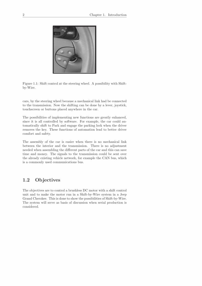
Figure 1.1: Shift control at the steering wheel. A possibility with Shift-by-Wire.
cars, by the steering wheel because a mechanical link had be connectedto the transmission. Now the shifting can be done by a lever, joystick,touchscreen or buttons placed anywhere in the car.
The possibilities of implementing new functions are greatly enhanced,since it is all controlled by software. For example, the car could au-tomatically shift to Park and engage the parking lock when the driverremoves the key. These functions of automation lead to better drivercomfort and safety.
The assembly of the car is easier when there is no mechanical linkbetween the interior and the transmission. There is no adjustmentneeded when assembling the different parts of the car and this can savetime and money. The signals to the transmission could be sent overthe already existing vehicle network, for example the CAN bus, whichis a commonly used communications bus.
1.2 Objectives
The objectives are to control a brushless DC motor with a shift controlunit and to make the motor run in a Shift-by-Wire system in a JeepGrand Cherokee. This is done to show the possibilities of Shift-by-Wire.The system will serve as basis of discussion when serial production isconsidered.

1.3. Methods and Execution 3
1.3 Methods and Execution
After the first few weeks of reading to get to know the project, theSimulink model of the system was examined. When the shift controlunit arrived from the manufacturer, there was a week of soldering andattaching cables. Several hardware errors were corrected before themotor showed any signs of life. Then followed programming which wasdone in C and flashed onto the microcontroller. The performance ofthe motor was compared to the model and then evaluation was doneat the end.
The simulations and modelling have been done in Matlab Simulink, pro-gramming in CodeWright and compilation by Cosmic Compiler. Theresulting file is flashed to the microcontroller by Zap Debugger.
1.4 Organization
The work has been done from February to August 2003 at Daimler-Chrysler AG in Esslingen in Germany as the final part of my Masterof Science education in Applied Physics and Electrical Engineering atLinkopings universitet.
1.5 Thesis Outline
Chapter one is an introduction to the project and it describes Shift-by-Wire and why it is developed. Chapter two describes the backgroundfrom where I started working; how an automatic transmission works,what the actuator should do and some alternative solutions. In chapterthree there is a description of the brushless DC motor and how tocontrol it. Chapter four presents the Simulink model of the system andthe results from a simulation. In the fifth chapter, the Shift ControlUnit is described along with the operating system, the communicationpossibilities with a computer and the control algorithm for the motor.Chapter six is a presentation of the motor performance and how itresponds to different tests. Finally, chapter seven sums up and looksinto the future.
Chapter 2
Physical Prerequisites
2.1 The Automatic Transmission
The project is carried out on the Chrysler 45RFE transmission, whichis a four-gear rear-wheel-drive automatic transmission in the 1999 JeepGrand Cherokee with a 4.7-liter V8 engine. The details of an automatictransmission will not be described here since it is not necessary for theunderstanding of this thesis. However, some basic knowledge is nice tohave for the overall picture.
A modern automatic transmission consists of a combination of me-chanical, hydraulic and electrical technology that work together in aquite fascinating way. The different gear ratios depend on the designof the planetary gear system, see figure 2.1. It consists of a ring gear,a sun gear and two or more planet gears, kept together by a planetcarrier. Each of these three components can be used as input, outputor be held stationary. The gear ratio is determined by choosing whichpart plays which role.
For example, the ring gear can be connected to the input shaft comingfrom the engine, the planet carrier to the output and the sun locked.If the ring is turned the planets walk along the sun gear causing theplanet carrier to turn the output shaft in the same direction as theinput shaft but at a slower speed. By using another combination ofinput, output and lock other ratios can be created. By connecting sev-eral of these planetary gear systems in series very specific ratios canbe created, adjusted to desired values for all forward and reverse gears.
The 45RFE uses three identical planetary gear systems to simplifymanufacturing and has the ratios 3, 5/3, 1 and 3/4 for forward op-
4

2.2. The Actuator 5
Ring gear
Planet carrierPlanet gear
Sun gear
Figure 2.1: A planetary gear system.
eration and 3 in reverse. For example, this means that in reverse, theinput to the transmission rotates three times as fast as the output.
The shifting procedure along with other things is controlled by hy-draulics. This is done in the control valve assembly, which is a metalplate with a complex maze of passages that distribute pressurized trans-mission fluid to the numerous clutches and bands inside the transmis-sion. To use a certain gear the transmission must lock some of theplanetary gears and some have to be connected to the output and theinput shafts. This is done by applying oil pressure at a certain com-bination of clutches and bands. Shifting between P, R, N and D isalso controlled here by a shift valve. Depending on the position of thevalve, pressure is distributed to different clutches. This shift valve iscontrolled mechanically by the shift lever in a normal transmission andfor example by a DC motor in a shift-by-wire system. More informationabout the 45RFE transmission is found in [9].
2.2 The Actuator
Since the entire mechatronical system has to be fitted into the trans-mission it has to be made relatively compact, even though there is morespace in a 45RFE than in many other transmissions.
Figure 2.2 shows the actuator which is added inside the normal trans-mission. It consists of a Brushless DC motor (BLDC motor) and a gearreduction of 1:200 to make sure the motor has enough torque to move

6 Chapter 2. Physical Prerequisites
BLDCmotor
Bevel gear
Worm gear
Connection toshift valve
Figure 2.2: Actuator: DC motor and a gear reduction of 1:200.
the shift valve. The worm gear acts as a lock for the larger wheel so itcannot turn unless the motor is turning. This arrangement also makessure that the shift valve is not moving out of position during driving,if there is an interruption in the control signal to the motor.
When the motor turns, the horizontal bar moves and creates a linearmotion of the shift valve inside the control valve assembly. The positionof the shift valve controls the hydraulics inside the transmission.
2.2.1 Shift Valve Positions
The distances that the shift valve has to move are P-R: 14.6 mm, R-N:10.5 mm and N-D: 10.3 mm. That equals 14.9, 10.7 and 10.4 rotationsfor the motor. There is a small range of about a millimeter that isallowed at each position. This makes the system forgiving because onemm corresponds to about one rotation for the motor, so stopping insidethe right range is quite easy.
During this thesis there was no time to build the entire system. Themotor was not connected to the gears nor to the shift valve. Insteadthe motor was tested on its own and the rotations of the motor werecounted when performing a shift. Later a position sensor will close theloop.

2.2. The Actuator 7
2.2.2 Position Sensors
To get closed loop control of the system, there is a linear position sensorfor the shift valve. This is a PLCD sensor for the Mercedes and a eddycurrent sensor for the Jeep.
PLCD sensor stands for Permanent Magnetic Contactless Displace-ment sensor and it consists of a soft magnetic core surrounded by acoil, wound around the entire length. On each end of the core is asecond short coil. A permanent magnet is attached to the shift valve.The magnetic flux causes localized magnetic saturation. The positionof the saturated area along the sensor axis can be determined by thecoil system. The output is a voltage (0 - 5V) which is sent to the A/Dconverter.
The reason for not using this kind of sensor in the Jeep is that it wastoo short for the distance, 35.4mm between P and D, so a Eddy Cur-rent sensor with maximum measuring length of 50 mm is used there.It uses Faraday’s law of induction which states that an eddy currentis created in a conducting material when it is placed in a changingmagnetic field. The sensor consists of a cylinder with a coil inside. Ametallic ring is placed around the cylinder sliding along its axis. Whenthe coil is driven by an alternating current a changing magnetic fieldis created that induces eddy currents in the metallic ring. The eddycurrents circulate in a direction opposite that of the coil, thus reducingthe magnetic flux in the coil and thereby its inductance. The distancebetween the coil and the ring affects the magnitude of the influence andfrom there the position of the ring can be determined.
There is also a control unit driving the AC and determining the impedanceof the coil. The output from the control unit is a current which goesthrough a resistor and the voltage from here is connected to the A/Dconverter. The accuracy of this sensor is extremely high, 0.15 nm. Themicrocontroller uses a 10 bit A/D converter which limits the accuracyto 50mm
210 = 49µm. The accuracy of the sensor is therefore excessive anda cheaper one could easily be used.
When the signal has been converted to digital values it passes througha low pass filter. This to get a less noisy signal to the controller. Thatis especially important when a derivative controller is used, since it issensitive to noise. The filter is a second order Butterworth filter whichcreates a nice signal to the controller.
For detailed information, see [15] (the PLCD sensor), [14] (the EddyCurrent sensor) and [7] (the low pass filter).
8 Chapter 2. Physical Prerequisites
30 40 50 60 70 80 90 100 110 120
20
40
60
80
100
120
140
160
180
Angle of the large actuator wheel [Degrees]
Torq
ue
required
by
moto
r[m
Nm
]
220
200PD
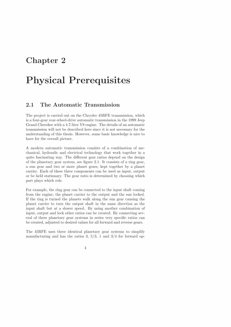
Figure 2.3: The torque characteristics when shifting from P to D. P isat 105 and D is at 20.
2.2.3 Parking Lock
When the motor turns, not only the shift valve moves but also theparking lock. The critical moment is the shift to P since there in allcars with automatic transmission is a mechanical lock to make rollingimpossible while in P. This is another system than the parking brake,which uses the wheel brakes to immobilize the car. The parking lock onthe other hand mechanically locks the output shaft of the transmissionby entering a block of metal into a wheel. This is further described in[2] and [13]. The reason for having a parking lock is a legal issue legis-lated by NHTSA (National Highway Traffic Safety Administration) inUSA and by EU legislation. See [11] and [8].
The parking lock consists of a spring and a cone shaped cylinder thatforces the block of metal into a gear inside the transmission. In an ex-treme case, when the car is fully loaded and parked at a steep hill, thetorque on this gear can be up to 900 Nm. Then a large force is neededto pull the parking lock out of the gear and this force specifies the mo-tor performance. The torque required by the motor is shown in figure2.3. As seen, the torque required to move only the shift valve, between90 and 20, is much smaller than to remove the parking lock. If theparking brake matter was solved in another way, then a weaker/cheapermotor could be used and at the same time the system could be madefaster. BMW for example solved it with hydraulics. That is not done inthis project since too much of the transmission would have to be rebuilt.

2.3. Add-on or Integrated Shift-by-Wire 9
Problems could occur with the parking lock if there was an error inthe Shift-by-Wire system. Since the worm gear locks the position ofthe larger wheel, what would happen if the electronic system failedwhile the parking lock was in place? It would be impossible to movethe car. This is not acceptable and a manual override is installed whichallows the wheel to slide when a lever on the outside of the transmissionis pulled. Then it is possible to drive the car to service.
These torque calculations have been made by a student in an earlierproject at DaimlerChrysler [4].
2.3 Add-on or Integrated Shift-by-Wire
There are two separate designs that car manufacturers have used fortheir Shift-by-Wire systems, the integrated and the add-on system.This thesis deals with the integrated system, which means that theactuator is placed inside the transmission housing. With the add-onsystem the actuator is placed outside attached to the shaft that earlierwas connected to the shift lever in the car interior. DaimlerChrysleris researching on both these since they have different advantages, butthe integrated system will probably eventually be the more economicaland practical solution.
The advantage with the add-on principle is that no alterations to thetransmission itself are necessary, which means that a prototype canbe built much faster. The actuator and sensor are just added on theoutside of a normal transmission. One problem which arises is thatthe heat from the exhaust pipe, which runs close by, can disturb thesystem. This leads to heat insulation difficulties.
The integrated system is car model independent, meaning that whenthe transmission is ready it can be placed in any car model that usedthe transmission earlier, since no outer alterations are made. This flex-ibility is of course desirable. However, the system is specific to thistransmission where the add-on system can easily be applied to othertransmissions.
2.4 Shifting using Electromagnetic Valves
The shifting in automatic transmissions between the driving positionsP, R, N and D has always been controlled mechanically, but the gearshifting has been done electronically. That means that it is possible
10 Chapter 2. Physical Prerequisites
to control the hydraulics in the transmission electronically, and that isdone by electromagnetic valves. Could not the same method be usedfor the driving positions P, R, N and D?
Yes, and that would be the most elegant solution. Then the actuatorwould be unnecessary and the entire transmission would be controlledby the electromagnetic valves. There are two reasons why this hasnot been done here. The first one is that too much of the transmissionwould have to have been rebuilt. That could have been done but wouldhave been a considerably larger project requiring more time. Secondlythere is now the possibility to build a car in serial production with orwithout Shift-by-Wire with basically the same transmission. It couldfor example be extra equipment for a couple of years to see the publicopinion.
2.5 Competitors
Other car manufacturers are also developing shift-by-wire systems andsome already have cars in serial production. BMW has a integratedsystem developed by the German drive line specialist ZF and Bosch fortheir 7 series. It is an electrohydraulic system and a selector lever bythe steering wheel lets the driver control the driving mode.
Rolls Royce uses an add-on system for their automatic transmission.Alfa Romeo, Porsche and Audi also have a system with the same func-tion, but constructed completely different. It is a standard transmissionwith an automatic clutch and electronically controlled shifting by pad-dles at the steering wheel.
Chapter 3
Brushless DC Motors
3.1 The Principles
A normal DC motor consists of an inner rotor with a coil and an outerstator with magnets. When current is led through the coil in the rotora magnetic field is created that interacts with the magnets in the stator.This causes a rotation of the rotor. The rotation generates a changeof direction of the current through the coil, which leads to a continuedrotation. The transfer of the current to and from the rotor is handledby brushes that are fastened at the stator and press against the rotorand this is the weak point of a DC motor. The friction causes wear andlowered efficiency.
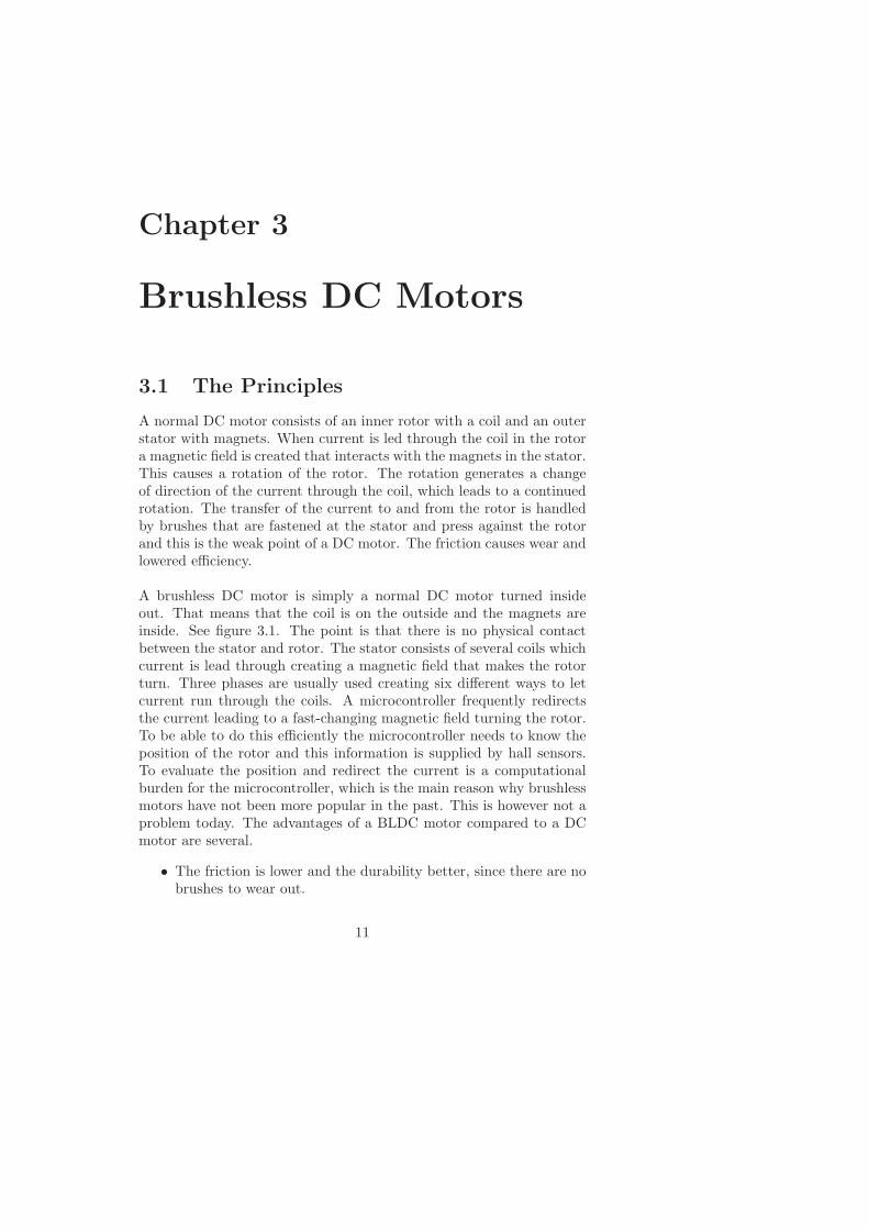
A brushless DC motor is simply a normal DC motor turned insideout. That means that the coil is on the outside and the magnets areinside. See figure 3.1. The point is that there is no physical contactbetween the stator and rotor. The stator consists of several coils whichcurrent is lead through creating a magnetic field that makes the rotorturn. Three phases are usually used creating six different ways to letcurrent run through the coils. A microcontroller frequently redirectsthe current leading to a fast-changing magnetic field turning the rotor.To be able to do this efficiently the microcontroller needs to know theposition of the rotor and this information is supplied by hall sensors.To evaluate the position and redirect the current is a computationalburden for the microcontroller, which is the main reason why brushlessmotors have not been more popular in the past. This is however not aproblem today. The advantages of a BLDC motor compared to a DCmotor are several.
• The friction is lower and the durability better, since there are nobrushes to wear out.
11

12 Chapter 3. Brushless DC Motors
A
B C
Figure 3.1: A three-phase BLDC motor.
• There is also no brush dust, which is important here where par-ticles in the transmission oil can damage the transmission.
• A BLDC motor has a high torque/volume ratio and by the posi-tion of the coil on the outside the cooling of the motor is easy.
• Perhaps the major advantage is however that a BLDC motor canbe made completely sealed off. That is important when, as inthis case, the motor runs completely in transmission oil insidethe transmission.
The permanent magnet usually consists of several pole pairs since thatcreates a larger torque than using only one pair. Naturally, the costalso increases with the number of poles. The BLDC motor used in thisproject consists of five pole pairs. See section 3.3.
3.2 Controlling a BLDC Motor
Two parameters of a normal DC motor are very easy to control, thespeed and the direction. To control the speed, vary the input voltage.To change the direction, simply reverse the polarity. The speed is oftencontrolled with pulse width modulation which is the same for normaland brushless motors. To be able to run a brushless motor, informationfrom for example hall sensors about the angular position of the rotor isnecessary. Current has to be directed through two of the three phases.The position of the rotor decides which phases should be active.

3.2. Controlling a BLDC Motor 13
34
T T
14
T T
Time
Time
U
U
Voltage
Voltage
Figure 3.2: PWM signals with 75% and 25% duty cycle respectively.
3.2.1 Pulse Width Modulation
Pulse width modulation, PWM, is a very popular method for control-ling the speed of electric motors. The principle is simple. For example,if the speed should be 50% of the maximum speed, the voltage is notturned down to 50%. Instead, the voltage is quickly turned on and offresulting in an average voltage of 50%. If 75% is required, called a dutycycle of 75%, then the voltage is kept turned off 25% of the time. Seefigure 3.2. If the switching frequency is high enough the motor will runat steady speed due to the inertia and inductance of the motor. Thismethod has some nice advantages:
• It is easy to implement in a microcontroller. Only one output pinis needed to control the speed.
• No battery power is lost at low speeds. If variable voltage is usedthen a possibility would be to place a resistor in series that wouldabsorb part of the voltage. However, that would mean that thebattery is still supplying maximum voltage and that power wouldbe wasted in the resistor.
• A motor controlled by PWM will generate more torque as thepulses use the full power supply in short intervals.
3.2.2 Hall Sensors
Knowledge of the angular position of the rotor is necessary for the mi-crocontroller. Without this information, it does not know how to applyvoltage to the three phases to create a torque. The angular position is
14 Chapter 3. Brushless DC Motors
ABC[010]
ABC[011]
ABC[001]
ABC[101]
ABC[100]
ABC[110]
Phase A
Phase BPhase C
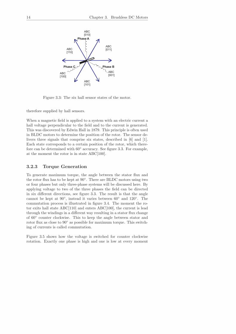
Figure 3.3: The six hall sensor states of the motor.
therefore supplied by hall sensors.
When a magnetic field is applied to a system with an electric current ahall voltage perpendicular to the field and to the current is generated.This was discovered by Edwin Hall in 1879. This principle is often usedin BLDC motors to determine the position of the rotor. The sensor de-livers three signals that comprise six states, described in [6] and [1].Each state corresponds to a certain position of the rotor, which there-fore can be determined with 60 accuracy. See figure 3.3. For example,at the moment the rotor is in state ABC[100].
3.2.3 Torque Generation
To generate maximum torque, the angle between the stator flux andthe rotor flux has to be kept at 90. There are BLDC motors using twoor four phases but only three-phase systems will be discussed here. Byapplying voltage to two of the three phases the field can be directedin six different directions, see figure 3.3. The result is that the anglecannot be kept at 90, instead it varies between 60 and 120. Thecommutation process is illustrated in figure 3.4. The moment the ro-tor exits hall state ABC[110] and enters ABC[100], the current is leadthrough the windings in a different way resulting in a stator flux changeof 60 counter clockwise. This to keep the angle between stator androtor flux as close to 90 as possible for maximum torque. This switch-ing of currents is called commutation.
Figure 3.5 shows how the voltage is switched for counter clockwiserotation. Exactly one phase is high and one is low at every moment

3.2. Controlling a BLDC Motor 15
ABC[110]
+U
-U
i
i
Actual fluxvector
ABC[100]
+U
-U
i
i
New fluxvector
Figure 3.4: The commutation process. The left figure shows the mo-ment prior to commutation and the right the situation afterwards forrotation counterclockwise.
HS A HS B HS C Phase A Phase B Phase C1 0 0 +U −U NC1 0 1 +U NC −U0 0 1 NC +U −U0 1 1 −U +U NC0 1 0 −U NC +U1 1 0 NC −U +U
Table 3.1: Commutation sequence for counterclockwise rotation de-pending on the hall sensor output.
during a complete rotation. Table 3.1 shows the same thing again plusthe states of hall sensors. The decision of how the current should be ap-plied is made from this table, but since large currents often are needed,the decision-making and the actual power supply are separated. Thelast stage before the motor is a three-phase bridge gate driver whichhandles the high currents, see figure 3.6. It receives on or off signalsto its high and low side switches which allows currents to run throughthe motor. Only one of the low side and one of the high side switchesare allowed to be active simultaneously.
3.2.4 System Overview
One way to summarize how to run the brushless DC motor is shownin figure 3.7. The hall sensors constantly supply the angular positionof the motor to the commutation handler. By measuring how oftenthe hall sensors change state it is easy to calculate the speed. Thedigital controller uses the target speed ωref and the actual speed ωact to

16 Chapter 3. Brushless DC Motors
Voltagephase A
30 60 90 120 150 180 210 240 270 300 330 360
Electrical angle
0
+U
-U
Voltagephase B
Voltagephase C
0
+U
-U
0
+U
-U
Figure 3.5: Voltage strokes applied for counterclockwise rotation.
BLDC
U
IA
I =B
I = 0C
-IA
PWM_AH
Phase A
PWM_BH PWM_CH
PWM_AL PWM_BL PWM_CL
Phase BPhase C
2+
U2
-
Figure 3.6: An example of a three phase bridge gate driver that handlesthe current supply to the motor. In this case PWMAH and PWMBL
are high.

3.3. Brushless Motor MM41 35-3L 17
PWMgenerator
Bridge gatedriver BLDC
Hall sensorsCommutation
handler
Digitalcontroller
+ U -
Dutycycle
ωrefSpeed
calculationωact
Direction
PWM signal
A, B, CHigh & Low
Shift Control Unit
Figure 3.7: System overview.
determine the new duty cycle. It also sends the desired direction to thecommutation handler. This is where the directions of the currents tothe motor are decided. It uses a table like table 3.1 and sends six signalto the bridge gate driver’s six switches. The PWM generator creates theappropriate signal from the duty cycle and sends it to the bridge gatedriver. The switches that are set to be open are then not constantlyopen but instead turned on and off at the high PWM frequency. Thiscreates the right magnitude and direction of the current. Finally thevoltages over the three phases is similar to those in figure 3.8.
3.3 Brushless Motor MM41 35-3L
The motor used is supplied by the French company MMT, MovingMagnet Technology. It has five pole pairs which means that the rotorconsists of five magnets, totally 10 poles. See figure 3.9. After onerotation each hall sensor has switched value 10 times, and no two haveswitched at the same time. That means that the hall state changes 30times during one rotation. To avoid misunderstandings, two separaterotations must be defined. One mechanical rotation, 360 mechanicaldegrees, is one turn for the motor. But during that time 5 electricalrotations are made because it passes the north and south side of the ro-tor 5 times. In an example like figure 3.1 there is no difference betweenthese two since it only has one pole pair. More pole pairs could make

18 Chapter 3. Brushless DC Motors
Voltagephase A
30 60 90 120 150 180 210 240 270 300 330 360
Electrical angle
0
+U
-U
Voltagephase B
Voltagephase C
0
+U
-U
0
+U
-U
Figure 3.8: Voltages for each phase from the bridge gate driver.
the motor slower, since it has to switch current direction 30 times perrotation compared to just 6 times. The advantage with more poles isthat the torque is higher.
Since the position sensor is not yet connected, these hall sensor sig-nals are not only used to obtain the rotor position, but also to estimatethe position of the shift valve, had it been connected. P is set to posi-tion 0. R is 14.9 rotations away, which equals 446 hall state changes.In the graphs in the following chapters there are steps from for example0 to 446. This is explained further in section 5.2.2.
3.3.1 Specifications
The specifications of the motor which have been used during modellingof the motor are shown in table 3.2. The stall torque is well above thearound 200 mNm which is the maximum in figure 2.3, which meansthat the motor is strong enough.
3.4 Sensorless Driving
The development of BLDC motors is now going in the direction ofsensorless motors, which means that the hall sensors are removed. Thenthe rotor position has to be measured in some other way. There are atleast three reasons for this progress.
• Productions costs. If a system like this would come to the point

3.4. Sensorless Driving 19
S1S2
S3
H2
H3 H1
Figure 3.9: The MMT motor with five polepairs.
MMT MM41 35-3LMaximum speed 6000 rpmPeak stall torque 946 mNmPeak torque at maximum speed 169 mNmKm 0.018 Nm/AKe 0.018 V/(rad/s)Inertia, J 27 gcm2
Inductance, L 250 µHResistance, R 0.2 Ω
Table 3.2: Specifications for the BLDC motor from MMT.
of mass production, the manufacturer has to try to cut the pro-duction costs. Every euro saved on each car is important in aseries of 100000 cars. The cost of the sensors and the wiring isthen considerable.
• Impossibility to make additional connections between the motorand the control unit. With normal BLDC control the sensedinformation must be sent to the control unit using three extracables. This is not always possible.
• Errors in systems like this often occur in cables and sockets. Fewercables lead to fewer potential errors.
It has been shown that by sensing the voltage at the third phase, the onenot connected to the power, the position of the rotor can be estimated.A method usually called back-EMF sensing will be discussed here.

20 Chapter 3. Brushless DC Motors
U
2+
IA
I =B
I = 0C
-IA
PWM_AH
Phase A
PWM_BH PWM_CH
PWM_AL PWM_BL PWM_CL
Phase BPhase C
U
2-
uiA
uiB
uiC
uVA
uVB
uVC
Figure 3.10: The three phase bridge driver with the back-EMF voltagesuiA, uiB and uiC shown.
3.4.1 Back-EMF Sensing
When the current is commutated, back-EMF voltages are induced inthe stator windings. Let us assume that phases A and B are poweredby the PWM signal and phase C is not connected, as in the followingscenario. See also figure 3.10. uV A, uV B and uV C are the branch po-tentials, i.e. the voltage between one power stage output and ground.uiA, uiB and uiC are phase back-EMF voltages induced.
PWM → PWMAH , PWMBL
uV A = u/2, uV B = −u/2iA = −iB , iC = 0
The desired variable uiC cannot be measured, but uV C can. Therelationship between the two variables can be calculated from figure3.10. How it is done is shown in [3]. The equation is only valid whenphase C is not powered. Since
uV C =32uiC (3.1)
can the induced back-EMF voltage uiC be calculated by measuring thevoltage uV C . The voltages for the other phases can be calculated ac-cordingly. During one revolution, 0-360 electrical degrees, the voltageuV C varies according to the pattern in figure 3.11. The shaded rect-angles show where equation 3.1 is valid. Those are the areas wherephase C is not connected to power. Then 30 degrees after each zero-crossing point the commutation occurs and phase C becomes powered.By sensing these zero-crossing points it is possible to control the com-mutation without the hall sensors. One can also vary the angle fromthe 30 degrees after the zero-crossing point to get a better behavior.

3.4. Sensorless Driving 21
3603303002702402101801501209060300
Electrical degrees
Vo
lta
ge
at
U
390
VA
Figure 3.11: Branch voltage during one revolution. The angular posi-tion of the rotor can be estimated by sensing the zero-crossing points,here at 180 and 360.
This deviation is called switching angle and can be adjusted to fit theload applied to the system.

Chapter 4
System Modelling
A Simulink model of the system has been made in two previous theses,[13] and [15]. Some small modifications were made, such as addingmeasuring noise. The model could be used as it was, even though itwas made for a normal DC motor. The behavior seemed to fit also forthis motor. Only some constants had to be calculated in another way.Figure 4.1 is the model of the entire system. It is a closed loop withthe actuator, controller and position sensing.
4.1 Modelling a DC Motor
It is quite easy to model a normal DC motor so that the angular velocityω(t) is controlled by the applied voltage uapp(t). The model is entirelybased on some fundamental laws of physics. Further details can befound in [10] and [16]. To start with, Kirchhoff’s law can be used on thecircuit in figure 4.2, resulting in equation 4.1 describing the electricalpart of the motor. Newton’s second law describes the mechanical part,how the torque affects the system. It states that the inertial load J timesthe angular acceleration is equal to the sum of all torques, equation 4.2.
uapp(t) = Ri(t) + Ldi(t)dt
+ uemf (t) (4.1)
Jdω(t)
dt=
∑τi (4.2)
Faraday’s law of induction states how a change in the magnetic envi-ronment of a coil causes a voltage (electromagnetic force, emf) to beinduced in the coil. This is the same principle as in the eddy currentsensor, chapter 2. The back emf, uemf (t), is proportional to the an-gular velocity ω(t). Lorentz’s force law describes the force upon a coilin a magnetic field. That leads to that the produced torque τ(t) is
22

4.1. Modelling a DC Motor 23
Shift Lever Position
-K-
Sensor gain
PositionDigitized value
Sensor + A/D Converter
PRND Actuator
Measured Position
Driver Wish
Target Position
Measured PositionPWM Voltage
Digital Controller
Control voltage
Figure 4.1: A model of the total system.
proportional to the current i(t). These two laws lead to the followingexpressions,
uemf (t) = Ke ω(t), (4.3)
τ(t) = Km i(t). (4.4)
Ke [V/(rad/s)] is the emf constant and Km [Nm/A] is the armatureconstant, which are both related to physical properties of the motor,such as magnetic field strength and number of turns of the coil. Thesehave the same numerical value in SI units. By combining equations 4.1and 4.3 can the electrical part of the motor be described by
uapp(t) = Ri(t) + Ldi(t)dt
+ Kb ω(t). (4.5)
Equations 4.2 and 4.4 lead to the mechanical part
Jdω(t)
dt= Km i(t) − Kf ω(t), (4.6)
where Kf ω(t) is the result of the friction in the motor. Friction alsocomes from the transmission oil the motor is running in. This frictionis extremely temperature dependent. This leads to two differentialequations describing the system which can for example be used in astate-space representation,
di(t)dt
= −R
Li(t) +
1L
uapp(t) − Kb
Lω(t), (4.7)
dω(t)dt
=Km
Ji(t) − Kf
Jω(t). (4.8)

24 Chapter 4. System Modelling
+
+
- -
i(t)
R
L
u (t)emf
u (t)app
DC motor Load
J
τ(t)torque
ω(t)angular velocity
K (t)
viscousfriction
ωf
Figure 4.2: A simple model of a DC motor.
The state-space system has two states, the current i(t) and the angularvelocity ω(t). Input is the applied voltage uapp(t) and output is theangular velocity ω(t),
ddt
[i(t)ω(t)
]=
[ −RL −Ke
LKm
J −Kf
J
] [i(t)ω(t)
]+
[1L0
]uapp(t)
y(t) = [0 1][
i(t)ω(t)
].
(4.9)
From this representation the transfer function can be derived. Methodsare described in for example [5] and lead to the transfer function fromuapp(t) to ω(t),
G(s) =ω(t)
uapp(t)=
Km
JLs2 + (RJ + KfL)s + RKf + KeKm. (4.10)
Normally the friction Kf is small, resulting in that RJ >> KfL andKeKm >> RKf . These significantly smaller terms are neglected andthe transfer function for a DC motor is often written as
G(s) =Km
JLs2 + RJs + KeKm. (4.11)
By dividing both the numerator and denominator by KeKm, the timeconstants can be identified.
G(s) =1/Ke
RJKeKm
LRs2 + RJ
KeKms + 1
(4.12)

4.2. Modelling the Gears 25
1angular velocity
1s
integrator
R
Resistance
Km
Km
1s
Integrator
1/L
Inductance
Ke
Emf
1/J
1/J
1
Voltagedi/dt i acc omegatorque
Emf voltage
Figure 4.3: A Simulink model of a DC motor.
With the mechanical time constant τm = RJKeKm
[s] and the electricaltime constant τe = L
R [s] the expression finally looks like
G(s) =1/Ke
τmτes2 + τms + 1(4.13)
This is also the transfer function for a BLDC motor. The only differ-ence is the way to calculate the resistance and inductance, since themotor has three phases (see chapter 3 and especially figure 3.6). Thisdoes not affect the model. Only the way to calculate the motor con-stants Ke, Km, τm and τe is changed. This is described in [16].
The resulting model of the motor in Simulink is figure 4.3. It is onepart of the PRND Actuator block in figure 4.1.
4.2 Modelling the Gears
To be able to move the shift valve the speed needs to be reduced. Thisof course makes the system slower, but also allows the motor to run athigh rpm. The gear ratio in this system is 1:200, which means that 200turns for the motor equals one turn for the output. Since a DC motoris very fast this not a problem.
The gears consists of one bevel gear with the ratio 1:2 and one wormgear with ratio 1:100. See figure 2.2. The efficiency is in the modelestimated to about 80% for the bevel gear and 20% for the worm gear,leading to a total efficiency of about 15%.
4.3 Output from Simulation
The simulink model is used to find suitable control parameters. Fig-ure 4.4 shows the result of a simulation. The top plot shows the po-sition and the bottom the control signal during a step from P to R.

26 Chapter 4. System Modelling
500
400
300
200
100
00.1 0.15 0.20 0.05 0.350.30.25 0.4
time [s]
Po
sitio
nC
on
tro
lsig
na
l[V
] 10
8
6
4
2
0
-2
12
0.1 0.15 0.20 0.05 0.350.30.25 0.4time [s]
Figure 4.4: The results from a simulation with K= 0.5 and Td = 0.004.The y-axis in the position plot is scaled to match the hall state changes.
The position is the output from the A/D converter in figure 4.1, calledMeasured Position. The The control signal is the ouput from the digitalcontroller, called Control Voltage. Comparisons to the actual outputare made in chapter 6 and they show that the model fits the measureddata quite well.
The Simulink model is also used to verify that the motor is strongand fast enough. To see if the system has enough safety margin, theefficiency of the gears can be lowered and the motor torque needed canbe checked. One also has to make sure that the system is fast enoughand verify that the chosen gear ratio is the appropriate one. In this caseis the motor very strong with a high torque. By studying the torqueat different places in the model one can see that the gear ratio 1:200 isnot needed. Maybe 1:100 is more appropriate.
Chapter 5
Software
This chapter intends to explain how the control of the motor is codedand also which programmes and standards are used. An overview ofthe system is seen in figure 5.1. It shows both the Shift Control Unit(SCU), which runs the motor, and the communication with a computerused during development. The programmes running on the computerhandle the following.
• Let the user change the driver wish, i.e. shift driving position.
• Receive the results from a shift via a Matlab Graphical User In-terface.
• Supervise the traffic on the CAN bus and adjust control param-eters.
• Flash updates of the code to the SCU. This program can alsohandle real-time debugging of the system.
The SCU and the communication with the computer will be describedin the following pages. Last is a description of the control algorithmrunning on the SCU.
5.1 Shift Control Unit
The Shift Control Unit (SCU) contains all the electronics needed forcontrolling the motor. The heart is a microprocessor, HC12 from Mo-torola, which is very commonly used in cars. Also there are chips forcommutation of the BLDC motor, CAN communication, serial commu-nication and A/D converters.
27

28 Chapter 5. Software
Shift Control Unit
P R
N D
Driver Wish
Serial c
able
orC
AN
Se
ria
lca
ble
Matlab GUI
CA
Nb
us
KT_dPWM freq
Parameteradjustment
µC
OSEK Operating System
CANSerialPort
Computer
CommutationChip
Control loopPosition estimation...
...
BackgroundDebug Mode
Flash!Debug!
BD
MIn
terf
ace
BDM
HC12
Figure 5.1: Software overview.

5.1. Shift Control Unit 29
5.1.1 Microcontroller HC12
A microcontroller is a complete computer system with CPU (CentralProcessing Unit), memory, a clock oscillator and input/output on asingle integrated circuit. In this project the HC12 microcontroller fromMotorola was used which is a 16-bit device with 25 MHz maximum busspeed.
5.1.2 The Operating System
The operating system running on the SCU is developed by OSEK whichis a joint project of the automotive industry. OSEK is an abbreviationfor the German term ”Offene Systeme und deren Schnittstellen fur dieElektronik im Kraftfahrzeug” meaning ”Open Systems and the Corre-sponding Interfaces for Automotive Electronics”. The goal was to stan-dardize the interfaces of control units and make them more application-independent. This to make control units from different manufacturerscompatible, [12].
The OSEK operating system is designed for real-time applications andcapable of multitasking. It uses tasks with different priority and ascheduler organizes the sequence of task execution. Each task has itsown frequency deciding how often it should be activated. This projectuses two tasks ordered after priority.
• Task 1: Motor control.
• Task 2: Driver wish
The driver wish function listens to signals from the driver. If a shiftis requested, this function goes through a check list to see if a shift isallowed. With a positive result the motor control function is activated.It runs the motor to move the shift valve to the target position. Duringtesting two more tasks are used.
• Task 3: Change control parameter via CAN (see section 5.1.4).
• Task 4: Communicate with PC. (see section 5.1.3)
How often each task should be executed is set individually and task 1will interrupt any other task when the scheduler tells it to start.
5.1.3 Serial Communication
The SCU has a chip for serial communication and this is connected tothe serial port of a PC. In the motor control function there is a possibil-ity to sample a shift. For example can the position, control signal andhall state be saved in an array. When the control algorithm is finished
30 Chapter 5. Software
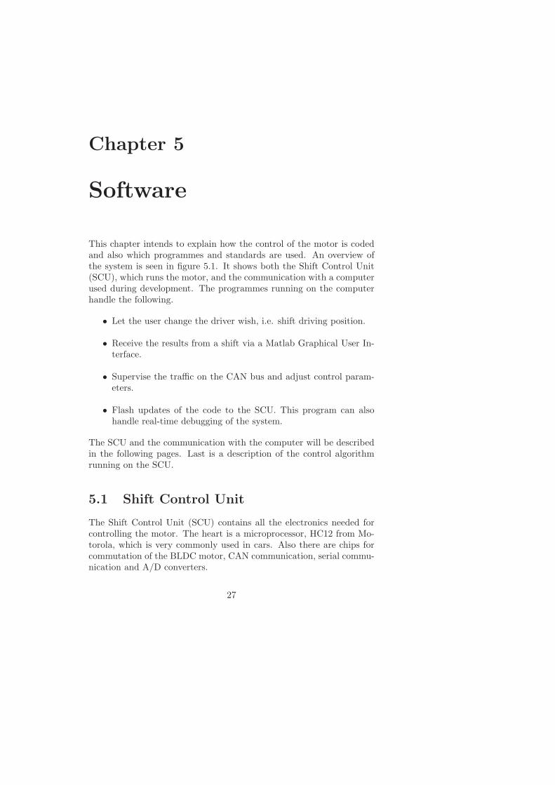
Figure 5.2: A screen shot of the Matlab Graphical User Interface thatreceives data from the SCU via the serial port.
and the shift valve is at the desired position, the sampled signals aresent over the serial cable along with the current control parameters.A simple GUI (Graphical User Interface) is created in Matlab whichcan receive signals directly from the serial port. It automatically plotsavailable signals and saves them to a file. This makes the evaluationeasier. The rise time and overshoot can be checked and the controlparameters can be adjusted accordingly. There is also a possibility tochange the driver wish from the GUI. The memory size of the CPUallows that around 2400 samples are saved, 800 each of position sam-ples, control signal and for example hall state. These 800 samples arecollected in about 300 ms.
5.1.4 Controller Area Network
Controller Area Network (CAN) is a serial communication bus for real-time control applications and was originally developed by Bosch. It isused for many time-critical applications like anti-lock braking systems,engine management and traction control. The speed is up to 1 Mbit/sand there is a good error detection. CAN is based on the so-calledbroadcast communication mechanism, which means that no receivingaddresses exist, only messages. These messages are identified by usinga message identifier. The identifier is a unique number within the net-work. A control unit checks the identifier of each message that passeson the bus to see if it is something of interest. In that case the entiremessage is read. All messages also have a priority. This is be important

5.2. Control Algorithm 31
when several stations compete for bus access.
In this project the CAN bus is used during the development phaseto send signals to the control unit. For example can the control pa-rameters, PWM frequency and driver wish be changed via a CAN pro-gramme on the PC. This makes the work much faster since no changesin the code are necessary. The driver wish will possibly still be sentover the CAN bus in serial production. The shift control unit will listento the bus and check all identifiers to see if the driver wish identifiershows up.
5.1.5 Background Debug Mode
Background Debug Mode (BDM) is a standard for debugging coderunning on embedded systems. A program, Zap Debugger from CosmicSoftware, is running on the computer debugging the code on the SCUin real-time. The communication is done through the parallel port onthe computer to a BDM interface which is connected to the SCU. Themain reason for using this is its flashing capabilities. When updatesin the code are done, they are flashed onto the microcontroller’s flashmodule. Through the Zap Debugger you can halt and start executionof the code, as well as step through it.
5.2 Control Algorithm
The goal for the control is to switch as quickly as possible between thepositions P, R, N and D without overshoot. Since the BLDC motoris running without being connected to the gears and thus without anyload not too much time has been spent on trying to optimize the perfor-mance and find the optimal parameters. The dynamics will probablychange too much when the system is complete. For example, the totalinertia of the system will increase. The control algorithm used has beendeveloped in an earlier thesis [7], and only some smaller modificationshave been made. It is a PD controller with some modifications for theD-part. First the continuous version,
v(t) = K(yref (t) − yact(t) + Tdd(βyref (t) − yact(t))
dt) (5.1)
where K is the proportional coefficient and Td the derivative coefficient.β is set to 0 to avoid spikes in the control signal when the referencevalue is changed, i.e. a shift occurs. This has not the desired effectsince the steps are large and the proportional part is large enough toalone maximize the control signal. However, the overall result is betterthan when β is set to one.

32 Chapter 5. Software
The discrete differential approximation is realized by the backward Eu-ler method. It computes the difference between the current sample andan earlier sample and divides by the time between the samples. Withβ = 0 the control signal
v[n] = K(yref [n] − yact[n] − Tdyact[n] − yact[n − N ]
TsN), (5.2)
where N is the number of samples used by the Euler backward method.A larger N generates a smoother derivative which is less sensitive tonoise. In this application is N=20. The derivative part is now onlydependent of the actual output and not changes in the reference sig-nal. The maximum control signal is 100% PWM so the following non-linearity is added:
if v > MAX_PWMu = MAX_PWM
else if v < -MAX_PWMu = -MAX_PWM
elseu = v
In task 1, where the motor control is placed, there is a loop that executesthe control algorithm a number of times. How many times the loopshould be iterated is a matter of adjustment. A short loop takes shortertime which means that during long time the motor is not controlled,since task 1 is not active. The position of the motor could change alot while other tasks are active and that results in a bad controller.But the loop cannot take longer time than the period time of the task.Then the other tasks will never be active. The ratio between the lengthand the period time of task 1 was set to about 85-90%, which led to40 iterations for the loop. That means that during one round of task 1the position is checked and the control signal is updated 40 times.
5.2.1 Accuracy Demands
The mechanical system is forgiving in the respect that there is a smallrange that is allowed for the shift valve for each driving position. Thatmeans that it is not essential for the shift valve to be exactly in place,there is about half a millimeter in each direction that also is permitted.Without this safety margin there would be problems with noise. In allsystems there are noise of different kinds and this will especially affectthe measurements of the position sensor.
To avoid constant corrections from the motor when noise is influencing
5.2. Control Algorithm 33
0 50 100 150 200 250400
500
600
700
800
0 50 100 150 200 250-50
0
50
100
Time [ms]
Time [ms]P
WM
Positio
n
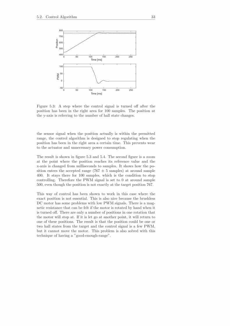
Figure 5.3: A step where the control signal is turned off after theposition has been in the right area for 100 samples. The position atthe y-axis is referring to the number of hall state changes.
the sensor signal when the position actually is within the permittedrange, the control algorithm is designed to stop regulating when theposition has been in the right area a certain time. This prevents wearto the actuator and unnecessary power consumption.
The result is shown in figure 5.3 and 5.4. The second figure is a zoomat the point where the position reaches its reference value and thex-axis is changed from milliseconds to samples. It shows how the po-sition enters the accepted range (767 ± 5 samples) at around sample400. It stays there for 100 samples, which is the condition to stopcontrolling. Therefore the PWM signal is set to 0 at around sample500, even though the position is not exactly at the target position 767.
This way of control has been shown to work in this case where theexact position is not essential. This is also nice because the brushlessDC motor has some problems with low PWM signals. There is a mag-netic resistance that can be felt if the motor is rotated by hand when itis turned off. There are only a number of positions in one rotation thatthe motor will stop at. If it is let go at another point, it will return toone of these positions. The result is that the position could be one ortwo hall states from the target and the control signal is a few PWM,but it cannot move the motor. This problem is also solved with thistechnique of having a ”good-enough-range”.

34 Chapter 5. Software
360 380 400 420 440 460 480 500 520
760
765
770
775
360 380 400 420 440 460 480 500 520
-5
0
5
Sample
Sample
Posi
tion
PW
M
Figure 5.4: A zoom of figure 5.3.
5.2.2 Position Estimation
Since the BLDC motor is not yet connected to the gears and the shiftvalve, there is also no position sensor signal to close the control loop.Instead a function was created that checks which hall state the motorcurrently is in. This function does not handle the actual commutation.That is handled by hardware in the commutation chip. This softwarefunction only counts the number of hall state changes and from thatit calculates the distance that amount would equal for the shift valve.The distance of 14.6 mm between P and R equals an angle change of26.8 degrees for the large actuator wheel. That equals 200 ·26.8 = 5351degrees for the motor, i.e. 14.87 rotations. During one rotation of themotor the hall state changes 30 times, see section 3.3. Thus, a shiftfrom P to R equals 14.87 · 30 = 446 hall state changes. The function isillustrated in figure 5.5.
One problem that has not been dealt with is caused by the tasks ofthe operating system. The function counting the hall state changesis placed in task 1. That means that any hall state change occurringduring another task is not registered. If task 1 is active 90% of the timethen 446 registered changes is only 90% of the real amount, since themotor also is running when other tasks are active.
The result of this problem is shown in figure 5.6. The state of thehall sensors are changing in the order 1-3-2-6-4-5, which correspondsto a counterclockwise rotation in figure 5.5. When it comes to sample

5.2. Control Algorithm 35
001
011
010
110
101
100
if NHS = 101position--;direction = 0;
if NHS = 100position--;direction = 0;
if NHS = 110position--;direction = 0;
if NHS = 010position--;direction = 0;
if NHS = 001position--;direction = 0;
if NHS = 011position--;direction = 0;
if NHS = 011position++;direction = 1;
if NHS = 010position++;direction = 1;
if NHS = 100position++;direction = 1;
if NHS = 001position++;direction = 1;
if NHS = 101position++;direction = 1;
if NHS = 100position++;direction = 1;
Figure 5.5: The principle for the hall state change counter function.NHS = New Hall State.
642, there is a jump in the other direction, from 2 to 3. That resultsin a position change in the wrong direction. This does not mean thatthe motor has changed direction. The reason is that sample 641 is thelast sample during task 1 and 642 is the first sample when task 1 startsagain. In the time in between, the motor has run, unknown how manyturns, and when task 1 starts again the hall state happens to be 3 anda decrease of the position is registered. After that the correct directionis set.
Important to remember is that this does not affect the actual commu-tation. What happens when an error occurs is only that the distanceto the target position is calculated falsely. The evaluation of the resultsis harder since it is not completely clear the exact distance the motorhas turned.
This could be solved by creating some kind of interrupt for this func-tion. Maybe could the control task be activated every time the hallstate changes. Then no state would be missed and the control signalcould be updated at every change. That was however not possible withthe software and actually not really important. The problem will notappear when a signal from a real position sensor is used. This functionis only used temporarily to calculate the distance the motor is turning.A signal from a sensor is updated independently of which task is active.

36 Chapter 5. Software
620 625 630 635 640 645 6500
1
2
3
4
5
6
7
620 625 630 635 640 645 650570
575
580
585
590
595
600
Sample
Sample
Positio
nH
all
st a
te
Figure 5.6: An error occurs in the hallstate counter function at sample642.

Chapter 6
Motor Performance
This chapter will describe the behavior of the motor and the testscarried out. First is a normal step which length corresponds to a shiftfor the transmission. The result is compared to the simulation andsome similarities are seen. Also a test with different PWM frequenciesis performed to find the optimal frequency. The motor is not connectedto the gears in any of these tests. It is running with no more load thanits own inertia. The position is estimated by counting the hall statechanges.
6.1 Adjustments of the Measurements
To compensate for the problem with the software tasks described insection 5.2.2, all graphs in this chapter are slightly adjusted. This isdone by measuring the top speed of the motor with an oscilloscopeto be independent of the operating system. This top speed, which isthe correct one, is measured to 5500 rpm. It is then compared to thecalculated top speed from the samples saved at the SCU. This valueis lower since it is affected by the problems with the tasks, typicallyaround 5000 rpm. The time axle is scaled by 5000/5500 to compensatefor this and the result is a plot which probably better corresponds tothe actual behavior.
6.2 Simulation Comparison
Figure 6.1 shows a shift between R and N. Such a shift equals 321 hallstate changes, from position 446 to 767. The graph shows the positionand the control signal and the similarities between the simulation andthe measurements are obvious. The motor is quickly coming to its topspeed and keeps running there for around 100 ms. During this time
37

38 Chapter 6. Motor Performance
0 50 100 150 200 250 300 350 400400
500
600
700
800
Measured Data
Simulation
Measured Data
Simulation
-20
0
20
40
60
80
100
120
0 50 100 150 200 250 300 350 400
Time (ms)
Time (ms)
PW
MC
ontr
olsig
nal
Positio
n
K = 1.8T_d = 0.004
K = 1.8T_d = 0.004
Figure 6.1: Comparison between the simulink model and measureddata.
the PWM control signal is at 100%. At time 100 ms the control signalis lowered and the position quickly stabilizes at the target position.When the position has been within the stipulated accuracy limits for100 samples the control signal is set to 0.
6.3 Control Parameter Settings
The system has been tested with different PID settings and reacts in afamiliar way to parameter changes. An increased proportional K valuemakes the system faster but also increases the overshoot. Since thecontrol signal is 100% for a large part of the step the time gain whenincreasing K is only marginal. A derivative part was added whichdampened the overshoot. Some tests were made with an integral partbut with no real improvements. It was therefor left out and finally aPD controller was used.
Until the motor is added into the transmission and can be tested inits real surroundings there is no point in optimizing the parameter set-tings. This report does therefore not contain any recommended settingsfor future use. Instead values that work and give a stable system havebeen found which can be used as a starting point for future optimiza-tion. The parameters will also need to be adjusted to the temperature,

6.4. PWM Frequency Test 39
K=1
750
800
850
900
950
1000
1050
1100
0 50 150 200100 250 300 350
Time [ms]
Po
sitio
n
Figure 6.2: A shift from N to D using 8 different PWM frequencies.
which affects the oil viscosity.
6.4 PWM Frequency Test
The control has been tested using eight different PWM frequencies, 117Hz, 469 Hz, 938 Hz, 1.875 kHz, 3.75 kHz, 7.5 kHz, 15 kHz and 25 kHz.The first test showed no difference at all, see figure 6.2. It is a shiftfrom N to D and the results can hardly be separated. This is becauseduring a large part of the step the control signal is maximized. Thismeans that the PWM duty cycle is 100% and the PWM frequency isnot important. Not until after about 100 ms is the PWM lower than100% and actually switching on and off. This shows that maybe thefrequency is not important for this application.
An other test was initiated. The step was made smaller so that theduty cycle never reaches 100%. Also, when the controller normallyturns off after having been in the right range for a certain time, a stepback again was begun. This test shows more difference between thefrequencies.
The frequencies between 938 Hz and 15 kHz all show the same be-havior and only one of them, 15 kHz, is shown in figure 6.3. It is thefastest to stabilize and take a step down. The lowest frequency hasa much bigger overshoot than the others do and therefor needs moretime to get to the target position. The second lowest has a smallerovershoot but is almost as slow. The highest frequency, 25 kHz, also

40 Chapter 6. Motor Performance
117 Hz
469Hz
15 kHz
K = 2.2
25 kHz
Time [ms]
Positio
n
180180180
170
160
150
140
130
120
110
100
90
800 50 100 150 200 250 300 350
Figure 6.3: Comparison between four different PWM frequencies. Boththe low and the high frequencies have problems.
had problems which was a bit surprising.
Another thing to consider is the frequency range audible to the hu-man ear. One common guideline is to use a frequency higher than 20kHz, which is the upper limit of which we can hear, if some resonancenoise is created. This is not important now though, since the motor isonly running in short intervals and furthermore in a car.
6.4.1 Problems at Low Frequencies
When a low PWM frequency is used the motor gets problem with thecommutation. It is shown in figure 3.8. Each phase is high during 120electrical degrees which is 24 mechanical degrees. When the motor isrunning at 5000 rpm, 83 rps, the time for one high phase is 1
83 · 24360 = 0.8
ms. If the PWM frequency is 117 Hz, its period is 8.5 ms, 10 times aslong. This means that the signal does not look like the one in figure3.8, since the PWM period is longer than the commutation period. Ifthe PWM duty cycle is only a few percent, the time when the signalis low is up to 8 ms long and during that time there will be no signalat all for several commutation periods. If the PWM period is aboutthe same as the commutation period you risk the situation in figure6.4 where one phase misses the PWM high time completely. The figureshows a PWM duty cycle of 20%. Every time phase A should be active,the PWM signal is low. This leads to that no current is going throughphase A. Problems like these occur when the PWM frequency is toolow compared to the speed and makes it hard to say what current the

6.4. PWM Frequency Test 41
PWM Signalduty cycle 20%
Commutationphase A
Time
Figure 6.4: Problems occur when the commutation and the PWM sig-nal have the same frequency. In this case will phase A always be low.
motor gets.
6.4.2 Problems at High frequencies
The behavior of the system when high PWM frequencies are used issurprising. It was fast but had problems when the position error wassmall. The reason for this is not completely clear. One possibility is animpedance problem. Since the motor basically is a coil the impedanceincreases with frequency. Low currents will be dampened and too smallto overcome the initial friction to move the motor. Another reasoncould be that heat production in the high current switches affects theresistance. With a higher PWM frequency for the switches the heatproduction is also larger.
Chapter 7
Conclusion
The nature of this thesis is one that leaves little to be analyzed andconcluded. The motor runs satisfactorily and that is the thesis objec-tive. Due to time limitations the motor was not tested in oil insidethe transmission. That has to be done to be able to come to any finalconclusions. Some things can however be said about the performanceof the system.
The switch from a normal to a brushless DC motor does not createany new major problems. Dedicated components help the microcon-troller to handle the more complex control algorithms. The use of thebrushless motor results in a slightly slower system than for a normalDC motor. However, since it has more torque, a good idea would beto change gear reduction to speed up the system. That of course de-pending on the speed and torque requirements. The results in chapter6 show that the motor runs at around expected speed and handles theshifting of the driving positions well. The control algorithm performssatisfactorily and is well adjusted to the system.
The developed software will help in future evaluations. The MatlabGUI makes it easy to quickly study the performance and to save thedata. Adjustments of the parameters can then be made via the CANbus.
7.1 PWM Frequency
The PWM frequency is not vital to the performance of the motor. Thisis shown in the test of the different PWM frequencies. The motor worksfine as long as the frequency is within a reasonable range. Not lowerthan 1 kHz where it is too close to the commutation frequency and not
42

7.2. Future Work 43
too high, more than 25 kHz, where the performance also goes down.The tests with frequencies from 1 kHz to 15 kHz showed good results.
7.2 Future Work
The next natural step will be to build the actuator into the transmis-sion. Then the real system can be tested. After that it is time to buildthe transmission into a car and evaluate it. Finally a decision has tobe made, if this is something we want in our future cars. Interestingwould also be to try a brushless motor without hall sensors. That wouldprobably be required if the system is to go into serial production.

44

References
[1] Analog Devices, Inc. Current Loop Control of a brushless DCmotor with hall sensors using the ADMC401, October 2001.
[2] M. Burgbacher and H. Nauerz. Shift-by-Wire fur automatischeGetriebe. DaimlerChrysler Corporation, February 2000. In Ger-man.
[3] L. Chalupa. Low Cost High Efficiency Sensorless Drive for Brush-less DC Motor using MC68HC(7)05MC4. Motorola, Inc, 1999.Rev. 0.2.
[4] A. Fischer. Konzeption eines ”override”-fahigen systems fur in-tegriertes shift-by-wire bei automatikgetriben. Technical report,DaimelerChrysler, 2002. In German.
[5] T. Glad and L. Ljung. Reglerteknik. Grundlaggande teori. Stu-dentlitteratur, Lund, Sweden, 2nd edition, 1989. In Swedish.
[6] P. Grasblum. 3-Phase BLDC Motor Control with Hall SensorsUsing DSP56F80. Motorola, Inc, September 2002. Rev. 1.0.
[7] D. Gullberg. Development of a motor control algorithm used in ashift-by-wire system. Master’s thesis, Linkopings universitet, 2002.
[8] EU Law. Commission directive 95/56/ecc relating to devicesto prevent the unauthorized use of motor vehicles, Nov 1995.1995L0056.
[9] B. Martin, C. Redinger, and H. Dourra. Chrysler 45RFE: A NewGeneration Real-Time Electronic Control RWD Automatic Trans-mission. DaimlerChrysler Corporation, January 1999.
[10] The MathWorks, Inc. Documentation for MathWorks Products(Release 13), April 2003. http://www.mathworks.com/support.
[11] NHTSA. Transmission shift lever sequence, starter interlock, andtransmission braking effect, Oct 2002. Title 49, Part 571, StandardNo. 102.
45

46 References
[12] OSEK organisation. OSEK/VDX Operating System, Jan 2003.www.osek-vdx.org.
[13] N. Rehberg. Modellierung einer elektromechanischen integri-erten shift-by-wire-aktorik fur den einsatz im automatgetriebe.Matrikel-nummer 720789, Fachhochschule Esslingen, Esslingen,Germany, June 2002.
[14] S. D. Roach. Designing and building an eddy current positionsensor. Sensors Online, (9), September 1998.
[15] E. Wahl. Lageregelung fur integriertes shift by wire. Master’sthesis, Fachhochschule Trier, Trier, Germany, March 2001.
[16] G. Younkin. Electric servo motor equations and time constants.Bulls Eye Marketing, Inc.

Notation
Abbreviations
AC Alternating CurrentA/D Analog/DigitalAG Aktiengesellschaft
BDM Background Debug ModeBLDC Brushless Direct CurrentBMW Bayerische Motoren WerkeCAN Controller Area NetworkCPU Central Processing Unit
D DriveDC Direct Current
GUI Graphical User InterfaceMMT Moving Magnet Technology
N NeutralNHTSA National Highway Traffic Safety Administration
OSEK Offene Systeme und deren Schnittstellen fur dieElektronik im Kraftfahrzeug
P ParkPID Proportional Integral Derivative (Controller)
PLCD Permanent Linear Contactless DisplacementPWM Pulse Width Modulation
R ReverseRPM Revolutions per minuteRPS Revolutions per secondSbW Shift-by-WireSCU Shift Control Unit
ZF Zahnradfabrik Friedrichshafen
47

48
Copyright
Svenska
Detta dokument halls tillgangligt pa Internet - eller dess framtida ersatt-are - under en langre tid fran publiceringsdatum under forutsattningatt inga extra-ordinara omstandigheter uppstar.
Tillgang till dokumentet innebar tillstand for var och en att lasa,ladda ner, skriva ut enstaka kopior for enskilt bruk och att anvanda detoforandrat for ickekommersiell forskning och for undervisning. Over-foring av upphovsratten vid en senare tidpunkt kan inte upphava dettatillstand. All annan anvandning av dokumentet kraver upphovsman-nens medgivande. For att garantera aktheten, sakerheten och tillgang-ligheten finns det losningar av teknisk och administrativ art.
Upphovsmannens ideella ratt innefattar ratt att bli namnd som up-phovsman i den omfattning som god sed kraver vid anvandning avdokumentet pa ovan beskrivna satt samt skydd mot att dokumentetandras eller presenteras i sadan form eller i sadant sammanhang somar krankande for upphovsmannens litterara eller konstnarliga anseendeeller egenart. For ytterligare information om Linkoping UniversityElectronic Press se forlagets hemsida http://www.ep.liu.se/
English
The publishers will keep this document online on the Internet - or itspossible replacement - for a considerable time from the date of publi-cation barring exceptional circumstances.
The online availability of the document implies a permanent per-mission for anyone to read, to download, to print out single copies foryour own use and to use it unchanged for any non-commercial researchand educational purpose. Subsequent transfers of copyright cannot re-voke this permission. All other uses of the document are conditionalon the consent of the copyright owner. The publisher has taken tech-nical and administrative measures to assure authenticity, security andaccessibility.
According to intellectual property law the author has the right to bementioned when his/her work is accessed as described above and to beprotected against infringement. For additional information about theLinkoping University Electronic Press and its procedures for publica-tion and for assurance of document integrity, please refer to its WWWhome page: http://www.ep.liu.se/
c© Johan WibergLinkoping, 16th December 2003
49