
Husqvarna Service Manual for Cutters Trimmers Pruners Hedge Trimmers Blowers
Upload
vince-occorsoCategory
view
668download
7
Brush Cutters, Trimmers,Pruners, Pruning saws,Hedge trimmers, Ice drills,Blowers
Workshop Manual101 90 75-26
For Husqvarna Parts Call 606-678-9623 or 606-561-4983
www.mymowerparts.com

1
Supplement to the workshopmanual for
brush cutters, trimmerspruners, pruning saws, hedgetrimmers, ice drills, blowers
1999
General recommendations ______________________ 2
1. Starter ___________________________________ 3
2. Ignition system ___________________________ 11
3. Fuel system _____________________________ 19
4. Centrifugal clutch _________________________ 37
5. Angle gear_______________________________ 45
6. Cylinder and piston ________________________ 51
7. Crankshaft and crankcase __________________ 63
8. Hydraulic unit ____________________________ 75
9. Attachments _____________________________ 79
10. Tools ___________________________________ 91
© Copyright Husqvarna AB, Sweden 1999
Contents
The supplement includes new products and modifications to products after theWorkshop Manual was printed in March 1997.
For complete information when servicing we recommend that the supplement isstudied together with the Workshop Manual.
(Order number 101 90 74-26)
For Husqvarna Parts Call 606-678-9623 or 606-561-4983
www.mymowerparts.com

2
502 51 03-01
General recommendations
Bear in mind:● Do not start the engine without the clutch drum and shaft
fitted. Otherwise there is a risk that the clutch can becomeloose and cause personal injury.
● Do not touch hot components, e.g. the muffler and clutchbefore they have cooled sufficiently to avoid burns.
● Avoid getting fuel or oil on your skin or in your mouth.Use barrier cream on your hands. This reduces the risk ofinfection and makes dirt easier to wash off.Long term contact with engine oil can represent a healthhazard.
● Never start the engine indoors. Exhaust fumes are poison-ous!
● Wipe up oil spills from the floor immediately to avoidslipping.
● Do not use tools that are worn or fit badly, for example onnuts and screws.
● Always work on a clean bench.
● Always work logically to ensure all parts are fitted correctlyand that nuts and screws are tightened.
● Use the special tools where recommended in order tocarry out the work correctly and efficiently.
Special toolsSome of the work described in the Workshop Manual requiresspecial tools. In each section where this is necessary there isa picture of the tool and an order number.
We recommend the use of special tools in order to avoidpersonal injury and to eliminate expensive damage to the partsin question.
Contact faces and gasketsEnsure all surfaces are clean and free from gasket residue.When cleaning use a tool that will not damage the contact face.Any scratches or unevenness should be removed using a flatfine cut file.
Sealing ringsAlways replace a sealing ring that has been dismantled. Thesensitive sealing lip can easily be damaged resulting in inferiorsealing capacity. Surfaces that the seal shall seal against mustalso be completely undamaged. Lubricate the sealing lip withgrease before it is fitted and ensure that it is not damaged e.g.by shoulders and splines on a shaft. Use tape or a conical sleeveas protection. It is important that the sealing ring faces in theright direction for it to act as it is intended.
The workshop used to carry out repairs must be equipped withsafety devices in accordance with local directives.
No one may carry out repairs without first having read andunderstood the contents of this Workshop Manual.
The boxes below can be found in appropriate parts of thismanual.
WARNING!The warning box warns of the risk for personalinjury if the instructions are not followed.!
NOTE!This box warns of damage to material if the instructions arenot followed.
The machine is type approved for safety in accordance withapplicable legislative demands with the equipment specified inthe Operator’s Manual. The assembly of other equipment oraccessories or spare parts not approved by Husqvarna canresult in the failure to meet these safety demands and that theperson carrying out assembly bears responsibility for this.
Poisonous fumesWhen using cleaning agents read the instructions carefully.
Ensure there is good ventilation when handling petrol and othervolatile fluids.
The engine’s exhaust fumes are poisonous. Test run the engineoutdoors.
Fire riskHandle fuel with respect, as it is extremely inflammable.
Do not smoke and ensure there are no open flames or sparksin the vicinity.
Make sure there is a working fire extinguisher close at hand.
Do not try to extinguish a petrol fire with water.
For Husqvarna Parts Call 606-678-9623 or 606-561-4983
www.mymowerparts.com
3
1.Starter
ContentsModels 322, 325Dismantling, assembling___________________________ 4
Replacing the drive dogs __________________________ 5
Models 32, Mondo, Mondo MegaDismantling, assembling___________________________ 6
Model 18HDismantling _____________________________________ 6
Assembly ______________________________________ 7
Models 140B, 141BDismantling, assembling___________________________ 8
AssemblyGeneral ________________________________________ 9
Replacing the drive dogs _______________________ 10
For Husqvarna Parts Call 606-678-9623 or 606-561-4983
www.mymowerparts.com

4
1
A
Starter
Models 322, 325DismantlingRemove the 3 screws and lift off the starter.
NOTE!Ensure the bushings (A) that guide the starter towards the fuel tank are not lost.
Offload the spring tension.
Remove the screw from the centre of thestarter pulley and lift off the starter pulley.
Offload the spring tension in the sameway as described for model 265.
Remove the screw in the centre of thestarter pulley. Carefully lift out the starterpulley from the starter housing.
AssemblyClean the component parts and assemblein the reverse order as set out for disman-tling.
AssemblyClean component parts before assem-bling.
Replace the return spring/starter pulleyand starter cord, if necessary.
Assemble the starter pulley.
Assemble a new starter cord.
Lubricate the spindle with a little greaseand fit the starter pulley.
Position the washer and tighten the screw.
Assemble a new starter cord. Slide it intothe starter pulley’s slot as illustrated andthen out through the cord guide in thestarter housing.
Make sure the knot on the end of the cordis as small as possible!
WARNING!Wear protective glasses.The return spring liestensioned in the starterand can fly out and causepersonal injury withcareless handling.
!
NOTE!The return spring and starterpulley are supplied pre-assembledand are fitted in the starterhousing as a single unit.Exercise care when opening thepackaging so that the spring doesnot fly out.
NOTE!A new starter cord can be fittedwithout the need of dismantlingthe starter!
For Husqvarna Parts Call 606-678-9623 or 606-561-4983
www.mymowerparts.com

5
1
504 91 06-05
Assemble the starter handle. Assemble the starter handle in the sameway as described for model 265, but tie adouble knot, as the cord is lighter.
Starter
Remove the circlip holdings the drivedog.
Lift out the drive dog and spring for re-placement.
Assemble in the reverse order as set outfor dismantling.
Remove the circlip and replace any dam-aged drive dogs or springs, if necessary.
Replacing the drive dogsDismantle the drive body.
Replacing the drive dogsFit the piston stop no 504 91 06-05 in thespark plug hole and loosen the nuts hold-ing the drive body.
Tension the return spring.
Check the spring tension.
Fit the starter on the engine body.
Do not forget the guide sleeves for the fueltank.
Tension the return spring. Pull out thestarter cord fully and lift it out of the cut-out in the starter pulley.
Now turn the starter pulley anticlock-wise, 6 turns.
Check the spring tension. With the startercord fully extended it should still be pos-sible to turn the starter pulley further, atleast a half turn.
For Husqvarna Parts Call 606-678-9623 or 606-561-4983
www.mymowerparts.com

6
1 Starter
Models 32, Mondo,Mondo MegaDismantlingDisconnect the electrical cables.
Remove the shaft complete with handle.
Models 32, Mondo,Mondo MegaDismantlingDisconnect the electrical cables by theengine body and remove the 4 screws(models Mondo and Mondo Mega have 3screws) that hold the shaft and handle onthe starter housing.
Lift off the shaft.
Dismantle the starter. Remove the 4 screws and lift off thestarter.
Model 32Pull out the electrical cables from the starterhousing using flat nose pliers.
Model MondoAlso dismantle the screw by the sparkplug.
AssemblyAssemble the starter handle.
AssemblyAssemble the starter handle in the sameway as described for model 265.
Tie a double knot, as the cord is lighterthan on model 265.
Model 18HDismantlingDismantle the air filter, throttle cable andcarburettor.
Remove the 4 screws holding the enginebody and gear housing.
Model 18HDismantlingThe starter is positioned between thecrankcase and the cutting equipmentdrive.
First dismantle the spark plug, air filter,throttle cable and carburettor.
Turn the trimmer upside down so that thescrews holding the engine body are ac-cessible.
Remove the 4 screws.
For Husqvarna Parts Call 606-678-9623 or 606-561-4983
www.mymowerparts.com

7
1
504 91 06-06
Starter
Assembly (also see model Mondo)Place a new spring cassette in position in the starter housing.
Replace the cord and attach as illustrated.
Assemble the starter pulley.
Assemble the starter handle (see model 265).
Tension the return spring.
Repeat tensioning the spring and fit the locking plates.
The following procedures are the same as for models 32, Mondo:
Remove the locking plates holding the starter pulley axially.
Offload the spring tension.
Dismantle the starter pulley and spring cassette from the starter housing.
Dismantle the starter.
Remove the 5 screws holding the starterhousing
Lubricate the ignition cable with a fewdrops of oil and remove the rubber grom-met in the cover.
Lift off the starter housing.
Dismantle the starter from the engine.
Assemble the piston stop no. 504 91 06-05 in the cylinder.
Unscrew the centrifugal clutch. Firstloosen it using a hammer and punch,anticlockwise.
Dismantle the centrifugal clutch.
For Husqvarna Parts Call 606-678-9623 or 606-561-4983
www.mymowerparts.com

8
1 Starter
Models 140B, 141BDismantlingRemove the screws and lift off the starter.
Models 140B, 141BDismantlingRemove the 4 screws holding the starteragainst the engine body.
Offload the spring tension and removethe starter pulley from the starter hous-ing.
Lift the starter cord out of the cut-out inthe starter pulley.
Offload the spring tension by allowing thestarter pulley to rotate backwards. Stopthe pulley using your thumb.
Remove the screw and washer from thecentre of the starter pulley.
Lift off the starter pulley.
Dismantle the return spring.
Clean and replace any damaged parts.
Carefully lift off the starter pulley andreturn spring.
AssemblyFit a new return spring in the starterhousing.
AssemblyFit a new return spring in the starterhousing. Exercise great care so that itdoes not fly out.
The return spring lies tensioned in thestarter housing and can fly out and causepersonal injury with careless handling.
Clean and replace any damaged parts.
WARNING!Use protectiveglasses.
!
Check that the spring’s mounting is fac-ing the right way!
WARNING!Use protectiveglasses.
!
For Husqvarna Parts Call 606-678-9623 or 606-561-4983
www.mymowerparts.com
9
1Starter
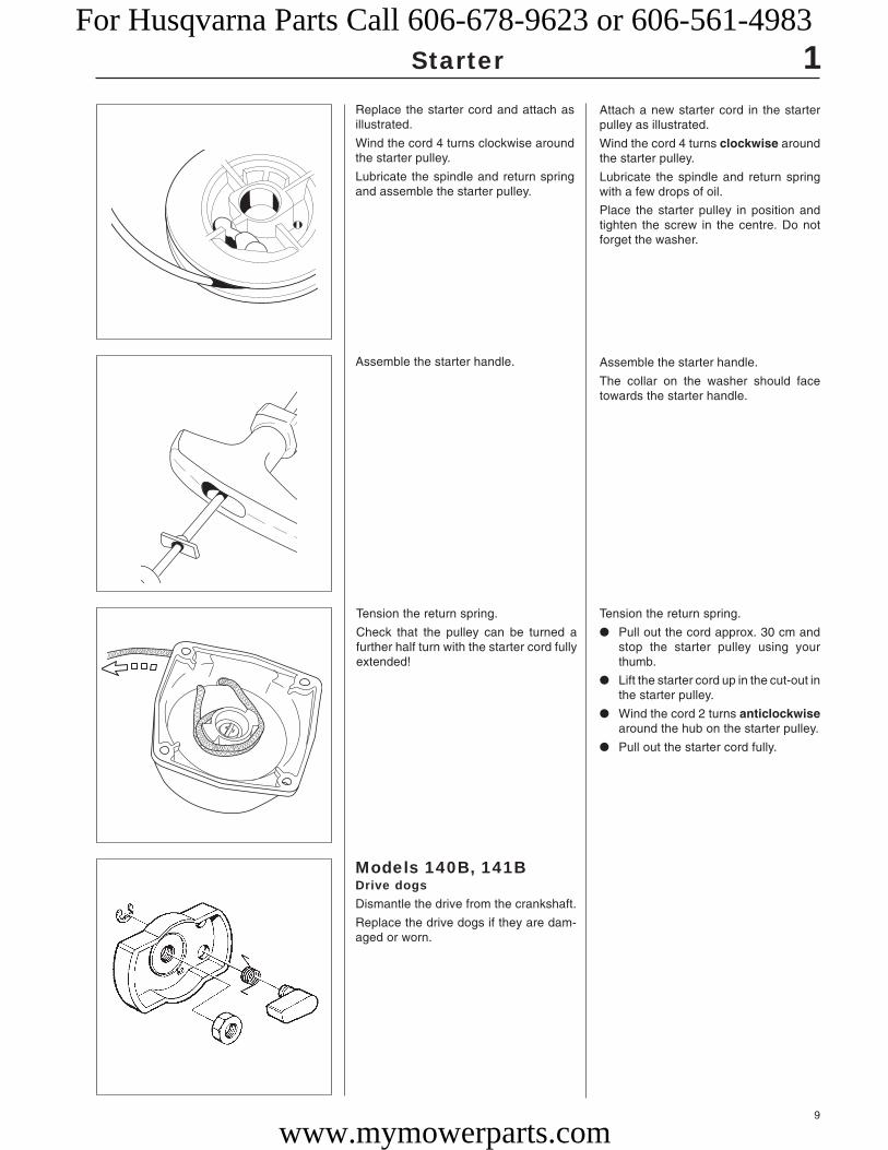
Tension the return spring.
Check that the pulley can be turned afurther half turn with the starter cord fullyextended!
Tension the return spring.
● Pull out the cord approx. 30 cm andstop the starter pulley using yourthumb.
● Lift the starter cord up in the cut-out inthe starter pulley.
● Wind the cord 2 turns anticlockwisearound the hub on the starter pulley.
● Pull out the starter cord fully.
Assemble the starter handle.
The collar on the washer should facetowards the starter handle.
Assemble the starter handle.
Attach a new starter cord in the starterpulley as illustrated.
Wind the cord 4 turns clockwise aroundthe starter pulley.
Lubricate the spindle and return springwith a few drops of oil.
Place the starter pulley in position andtighten the screw in the centre. Do notforget the washer.
Replace the starter cord and attach asillustrated.
Wind the cord 4 turns clockwise aroundthe starter pulley.
Lubricate the spindle and return springand assemble the starter pulley.
Models 140B, 141BDrive dogsDismantle the drive from the crankshaft.
Replace the drive dogs if they are dam-aged or worn.
For Husqvarna Parts Call 606-678-9623 or 606-561-4983
www.mymowerparts.com

10
1
503 21 22-01
Starter
Replacing the drivedogsSee chapter 2. “Ignition system, flywheel”with regard to engines that have the drivedogs fitted on the flywheel.
Replacing the drivedogs.See chapter 2. “Ignition system, flywheel”with regard to engines that have the drivedogs fitted on the flywheel.
Assembly, generalAssemble the starter in the reverse orderas set out for dismantling.
Assembly, generalAssemble the starter
Pull out the starter cord a little. Place thestarter in position. Release the startercord and check that the drive dogs en-gage in the starter pulley.
Tighten the screws.
NOTE!We recommend the use of an overdimensioned screw if the plasticthreads in the crankcase havebeen damaged for some reason.(no. 503 21 22-01).
For Husqvarna Parts Call 606-678-9623 or 606-561-4983
www.mymowerparts.com
11
2.Ignition system
Contents
Dismantling Models 322, 325, 18H __________________ 12
Models 140B, 141B ____________________ 13
Dismantling the flywheel ________________ 15
Assembly Models 322, 325 ______________________ 16
Technical data _______________________ 18
For Husqvarna Parts Call 606-678-9623 or 606-561-4983
www.mymowerparts.com

12
2
504 90 00-03
504 90 00-02
A
BB
Ignition system
DismantlingModels 322, 325Dismantle the cylinder cover, guard overthe muffler and spark plug.
Unhook the throttle cable from the carbu-rettor and remove the screws holding theclutch cover.
DismantlingModels 322, 325The following components must be dis-mantled for the ignition system to beaccessible.
Cylinder cover, guard over the mufflerand spark plug.
Remove the clutch cover and loosen theshort-circuit cable from the ignition mod-ule.
Disconnect the throttle cable from thecarburettor.
Remove the three screws holding theclutch cover.
Remove the clutch cover complete withthe shaft from the engine.
Loosen both ends of the short-circuitcable from the ignition module.
Dismantle the ignition module and thecentrifugal clutch.
Remove the remaining screw (A) holdingthe ignition module and both screws (B)that hold the centrifugal clutch.
Lift off the clutch and ignition module.
Model 18HRemove the spacer and washer and screwthe clutch down on the crankshaft.
Hold the flywheel and sharply tap theclutch a few times until the flywheel re-leases.
Model 18HRemove the long spacer and washer fromthe crankshaft.
Screw down the clutch a few turns on theshaft.
Hold the flywheel and sharply tap theclutch a few times until the flywheel re-leases.
For Husqvarna Parts Call 606-678-9623 or 606-561-4983
www.mymowerparts.com

13
2
A
B
B
A
B
Ignition system
Fold open the protective sleeve and sepa-rate the throttle cable.
Open the protective sleeve over the cablejoint and lift out the throttle cable runningto the throttle.
Pull apart the short-circuit cable connec-tor and remove the earth cable.
Separate the connectors for the short-circuit cable (A) and remove the earthcable (B) by removing the crankcasescrew.
Models 140B, 141BDismantle the fuel tank.
Models 140B, 141BEmpty the fuel tank and pull off the fuelhoses from the carburettor.
Note how the hoses are connected.
Remove the screws and lift off the fueltank.
Dismantle the ignition module. Dismantle the ignition module.
Remove the short-circuit cable (A) andboth screws (B).
For Husqvarna Parts Call 606-678-9623 or 606-561-4983
www.mymowerparts.com

14
502 50 22-01
2
A
A
A
B
AA
Ignition system
Remove the blower pipe. Loosen the hose clip and remove theblower pipe.
Dismantle the cylinder cover, heat guardaround the cylinder and the rotary valvefrom the carburettor.
Lift off the spark plug cap and unscrew thespark plug.
Remove the 3 screws (A) holding thecylinder cover and remove this and theheat guard from around the cylinder.
Dismantle the rotary valve (B) from thecarburettor by removing the 2 screwsholding the cover. Let the throttle hangfrom the throttle cable.
Dismantle the harness. Remove the harness from the tubularframe by removing both screws (A).
Remove the pipe bend.
Remove all screws and separate bothhalves of the fan housing.
Remove the pipe bend.
Remove the cleaning cover and all thescrews (12) holding both halves of the fanhousing.
Separate the halves.
For Husqvarna Parts Call 606-678-9623 or 606-561-4983
www.mymowerparts.com

15
504 91 06-05 502 50 23-01
502 50 22-01
502 50 23-01
2
504 91 06-05
Ignition system
Dismantling theflywheelFit the piston stop no. 504 91 06-05 andremove the nut holding the flywheel andwhere appropriate the plate with drivedogs.
Dismantling theflywheelAssemble the piston stop no. 504 91 06-05 in the spark plug hole.
Ensure the piston stop is screwed downto the bottom.
Remove the nut holding the flywheel andwhere appropriate the plate with drivedogs.
Remove the screws and lift off the ignitionmodule with the ignition lead, short-cir-cuit cable and grommet.
Remove the screws and lift off the ignitionmodule.
Remove the 4 screws holding the engineagainst the fan housing.
Lift off the engine.
Dismantle the engine from the fan hous-ing.
Screw in the piston stop no. 504 91 06-5in the spark plug hole and remove the 3screws holding the impeller using tool no.502 50 23-01.
Dismantle the impeller
NOTE!
The piston stop cannot be used onmodel 122.
For Husqvarna Parts Call 606-678-9623 or 606-561-4983
www.mymowerparts.com
16
502 51 49-01
504 90 90-01
502 51 94-01
2 Ignition system
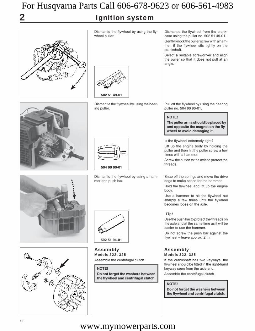
Dismantle the flywheel by using the fly-wheel puller.
Dismantle the flywheel from the crank-case using the puller no. 502 51 49-01.
Gently knock the puller screw with a ham-mer, if the flywheel sits tightly on thecrankshaft.
Select a suitable screwdriver and alignthe puller so that it does not pull at anangle.
Dismantle the flywheel by using the bear-ing puller.
Pull off the flywheel by using the bearingpuller no. 504 90 90-01.
Dismantle the flywheel by using a ham-mer and push bar.
AssemblyModels 322, 325If the crankshaft has two keyways, theflywheel should be fitted in the right-handkeyway seen from the axle end.
Assemble the centrifugal clutch.
AssemblyModels 322, 325Assemble the centrifugal clutch.
Snap off the springs and move the drivedogs to make space for the hammer.
Hold the flywheel and lift up the enginebody.
Use a hammer to hit the flywheel nutsharply a few times until the flywheelbecomes loose on the axle.
Tip!Use the push bar to protect the threads onthe axle and at the same time as it will beeasier to use the hammer.
Do not screw the push bar against theflywheel – leave approx. 2 mm.
Is the flywheel extremely tight?
Lift up the engine body by holding thepuller and then hit the puller screw a fewtimes with a hammer.
Screw the nut on to the axle to protect thethreads.
NOTE!
The puller arms should be placed byand opposite the magnet on the fly-wheel to avoid damaging it.
NOTE!
Do not forget the washers betweenthe flywheel and centrifugal clutch.
NOTE!
Do not forget the washers betweenthe flywheel and centrifugal clutch.
For Husqvarna Parts Call 606-678-9623 or 606-561-4983
www.mymowerparts.com

17
2
502 51 34-02
Ignition system
Assemble the ignition module and adjustthe air gap to 0.3 mm.
Assemble the ignition module.
Wait to connect the short-circuit cable tofacilitate the adjustment of the air gap. Itshould be 0.3 mm between the perma-nent magnets in the flywheel and theignition module.
Now fit the short-circuit cable and theremaining parts in the reverse order asset out for dismantling.
NOTE!
Do not forget the rubber bushingsbetween the clutch cover and thefuel tank.
For Husqvarna Parts Call 606-678-9623 or 606-561-4983
www.mymowerparts.com
18
2
Mondo
122L
Mondo Max
225L/LD
232L
Mondo Mega
225R/RD
232R
322
325
235R
240R
245R
250R
245RX
250RX
252RX
265RX
240RBD
235P
250PS
225E
18H
225H60/75
140B, 141B
132HBV
225BV/225HBV
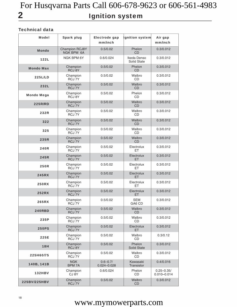
Champion RCJ8Y 0.5/0.02 Phelon 0.3/0.012NGK BPM 6A CD
NGK BPM 6Y 0.6/0.024 Ikeda Denso 0.3/0.012Solid State
Champion 0.5/0.02 Phelon 0.3/0.012RCJ 8Y CD
Champion 0.5/0.02 Walbro 0.3/0.012RCJ 7Y CD
Champion 0.5/0.02 Walbro 0.3/0.012RCJ 7Y CD
Champion 0.5/0.02 Phelon 0.3/0.012RCJ 8Y CD
Champion 0.5/0.02 Walbro 0.3/0.012RCJ 7Y CD
Champion 0.5/0.02 Walbro 0.3/0.012RCJ 7Y CD
Champion 0.5/0.02 Walbro 0.3/0.012RCJ 7Y CD
Champion 0.5/0.02 Walbro 0.3/0.012RCJ 7Y CD
Champion 0.5/0.02 Walbro 0.3/0.012RCJ 7Y CD
Champion 0.5/0.02 Electrolux 0.3/0.012RCJ 7Y ET
Champion 0.5/0.02 Electrolux 0.3/0.012RCJ 7Y ET
Champion 0.5/0.02 Electrolux 0.3/0.012RCJ 7Y ET
Champion 0.5/0.02 Electrolux 0.3/0.012RCJ 7Y ET
Champion 0.5/0.02 Electrolux 0.3/0.012RCJ 7Y ET
Champion 0.5/0.02 Electrolux 0.3/0.012RCJ 7Y ET
Champion 0.5/0.02 SEM 0.3/0.012RCJ 7Y GA6 CD
Champion 0.5/0.02 Walbro 0.3/0.012RCJ 7Y CD
Champion 0.5/0.02 Walbro 0.3/0.012RCJ 7Y CD
Champion 0.5/0.02 Electrolux 0.3/0.012RCJ 7Y ET
Champion 0.5/0.02 Walbro 0.3/0.12RCJ 7Y CD
Champion 0.5/0.02 Phelon 0.3/0.012RCJ 8Y Solid State
Champion 0.5/0.02 Walbro 0.3/0.012RCJ 7Y CD
NGK 0.6–0.7/ Kawasaki 0.4/0.016BPM 7A 0.024–0.028 Transistor
Champion 0.6/0.024 Phelon 0.25–0.35/CJ 8Y CD 0.010–0.014
Champion 0.5/0.02 Walbro 0.3/0.012RCJ 7Y CD
Ignition system
Technical data
Model Spark plug Electrode gap Ignition system Air gapmm/inch mm/inch
For Husqvarna Parts Call 606-678-9623 or 606-561-4983
www.mymowerparts.com

19
3.Fuel system
ContentsAir filter __________________________________ 20Tank venting ______________________________ 20Primer pump ______________________________ 20Carburettor _______________________________ 20Assembly ________________________________ 25Carburettor settings ________________________ 26CARB-designed carburettor __________________ 28Throttle cable _____________________________ 31Throttle __________________________________ 33Technical data _____________________________ 36
For Husqvarna Parts Call 606-678-9623 or 606-561-4983
www.mymowerparts.com

20
3
A
A
1
22
3
Fuel system
Air filterRemove the air filter cover and lift out theair filter for cleaning.
Air filterModel 141BPress down the catch on the cover overthe air filter housing and remove the coverand the air filter for cleaning.
Clean the filter in the same way as de-scribed above.
Fit the filter with the smooth side facing intowards the carburettor.
Ensure the support grille (A) is in position.
Tank ventingModel 141BThe tank ventilation is integrated in thefuel cap’s gasket
Blow through the flat hose to check that itis open.
Tank ventingModel 141BThe tank ventilation is integrated in thefuel cap’s gasket and can easily be dis-mantled for replacement.
Pull off the flat hose from the pin on therubber washer and blow through the hoseto check that it is not blocked. Check that the hole (A) is open.
Primer pumpModels 322, 325, Mondo, 18HThe primer pump facilitates cold starts.
The pump cannot be repaired and mustbe replaced if it stops working.
Note how the fuel hoses are connected tosimplify assembly.
Primer pumpModels 322, 325, Mondo, 18HThe primer pump has the task of facilitat-ing the start of the engine when cold. Thepump fills the carburettor with fuel beforeattempting to start the engine. This alsoprevents vapour bubbles from blockingthe narrow fuel channels.
If the pump does not work it must bereplaced.
Note how the fuel hoses are connected tosimplify assembly.
CarburettorModels 322, 325Disconnect the throttle cable from thecarburettor.
Dismantle the carburettor.
CarburettorModels 322, 3251. Disconnect the throttle cable from the
lever arm on the carburettor.
2. Loosen the carburettor screws.
3. Remove the screws holding the airfilter holder.
For Husqvarna Parts Call 606-678-9623 or 606-561-4983
www.mymowerparts.com

21
3
A
B
A
A
Fuel system
Model 141BDismantle the cover together with therotary valve and cable bracket.
Model 141BLoosen both screws (A) and lift off thecover together with the rotary valve andcable bracket.
Let the parts remain hanging from thethrottle cable if they are not damaged anddo not need to be replaced.
Loosen the carburettor screws and lift outthe air filter holder and carburettor.
Remove the fuel hoses from the carburet-tor.
Dismantle the carburettor from the cylin-der.
Model 18HDisconnect the throttle cable from thecarburettor.
Remove the screw (B) and unhook thethrottle cable from the lever arm on thecarburettor (A).
Model 18HDisconnect the throttle cable from thecarburettor.
Lift off the carburettor and note how thefuel hoses are connected.
Lift off the carburettor and note how thefuel hoses are connected.
For Husqvarna Parts Call 606-678-9623 or 606-561-4983
www.mymowerparts.com

22
3
A
BB
A
C
AB
Fuel system
Dismantle the carburettor from the cylin-der.
Remove the air filter support (A) and bothscrews (B) that hold the carburettor onthe cylinder.
Lift off the air filter holder and carburettorfrom the cylinder.
Remove the screws and lift out both dis-tance pieces.
Inspect the fibre distance piece with re-gard to crack formation.
Replace the distance piece if necessary.
Remove the screws (A), the fibre dis-tance piece (B) and the aluminium dis-tance piece (C).
Inspect the fibre distance piece with re-gard to crack formation. Replace the dis-tance piece if necessary.
Pull off the fuel hoses and lift out thecarburettor.
Lift out the carburettor and note how bothfuel hoses are connected to the carburet-tor (rubber hose on the straight nipple).
Assembling the carburettor –ZamaDesign, function and servicing correspondwith the Walbro carburettor.
Assembling the carburettor –ZamaZama has the same design and functionas the Walbro carburettor, which meansthat servicing is also carried out in thesame way.
The lever arm should lie flush with thecarburettor housing’s contact face.
For Husqvarna Parts Call 606-678-9623 or 606-561-4983
www.mymowerparts.com

23
3
1
12
L
H
Fuel system
Press out the main jet for possible re-placement using a suitable punch.
The main jet can be pressed out forpossible replacement using a suitablepunch.
Unscrew the jet needles. Unscrew the jet needles.
The plastic sleeves must first be removedusing a screwdriver on carburettors withmovement limiters.
Dismatle te pump diaphragm and the fuelscreen.
Remove the screws holding the coverover the pump diaphragm.
Lift off the cover, pump diaphragm andgasket.
Check the diaphragm (1) as described inthe workshop manual.
Carefully remove the fuel screen (2) us-ing, e.g. a needle.
Dismantling, assemblingModel 18HThe carburettor is made by Zama.
Dismantle the primer pump’s bellows andcover over the control diaphragm.
Dismantling, assemblingModel 18HThe carburettor is made by Zama.
It has the same principle design as theTillotson and Walbro carburettors.
Dismantle the primer pump’s bellows andthen the cover over the control diaphragm.
Inspect the control diaphragm and nee-dle valve in the same way as previouslydescribed.
NOTE! Note how the needles arepositioned.(For example, the H-needle is alittle shorter than the L-needle).
NOTE! When the new jet is fitted it mustnot be pressed in further than sothat the edge (1) on the jet liesflush with the carburettorhousing.
For Husqvarna Parts Call 606-678-9623 or 606-561-4983
www.mymowerparts.com

24
3 Fuel system
Assemble the carburettor and pressuretest it.
Wait to fit the movement limiters on the jetneedles.
Assemble the carburettor in the reverseorder as set out for dismantling.
The needle valve lever arm should beadjusted to a level flush with the carburet-tor housing’s contact face.
Dismantling, assemblingModel 141BRemove the screws and lift off cover withthe pump bellows.
Dismantling, assemblingModel 141BThis carburettor has a rotary valve in-stead of a throttle valve.
Remove the 4 screws and lift off coverwith the pump bellows.
Lift off the cover above the control dia-phragm and carefully remove the non–return valve. Check that it opens andcloses.
Continue to dismantle and assemble thecarburettor in the same way as describedfor model 122.
Lift off the cover over the control dia-phragm.
Carefully remove the non-return valveand check that it opens and closes bypressing together the valve’s short sideswith you thumb nail.
Hold the valve against a light to make iteasier to see whether it closes fully.
Continue to dismantle and assemble thecarburettor in the same way as describedfor model 122.
Wait to fit the movement limiters on the jetneedles.
NOTE! The control diaphragm and pumpdiaphragm should lie closest tothe carburettor housing!
For Husqvarna Parts Call 606-678-9623 or 606-561-4983
www.mymowerparts.com

25
3
1
2 3
4
5
6
A
A
B
Fuel system
AssemblyModels 322, 3251. First assemble the fuel hoses on the
carburettor.
Model 18HConnect the fuel hoses on the carburet-tor.
The thin hose (A) is connected to thenipple on the carburettor body (pumpdiaphragm).
Connect the throttle cable.
Tighten the air filter holder.
Clean or replace the air filter.
Connect the throttle cable (A) to the throt-tle valve’s lever arm.
Secure the cable guide (B) on the dis-tance piece.
Tighten the air filter holder.
Do not forget the gasket between thecarburettor and the distance piece!
Clean or replace the air filter before as-sembly.
Clean in tepid soapy water.
Fit the air filter cover.
5. Connect the throttle cable to the leverarm on the carburettor.
Make sure the cable enters the cor-rect slot in the clutch cover and in theguide on the air filter holder (6).
Assemble the remaining parts in the re-verse order as set out for dismantling.
NOTE! Do not forget the screw (5) thatholds the air filter holder againstthe distance piece.
2. Keep the air filter holder (1) in positionon the carburettor.
3. Slide in the carburettor screws (2).
4. Position the gasket (3) and screw to-gether the entire carburettor assemblyagainst the distance piece (4). Tightenthe carburettor screws crosswise.
NOTE!The hose, with the fuel filter in thetank, should be fitted on thecarburettor’s inlet side (pumpchamber).
Model 18HConnect the fuel hoses.
For Husqvarna Parts Call 606-678-9623 or 606-561-4983
www.mymowerparts.com

26
3
LH
A
Fuel system
Model 141BFit the distance piece on the cylinder.
Model 141BPay special attention that the distancepieces and gaskets face the right wayand do not block the impulse channelwhen fitted on the cylinder.
Secure the distance piece closest to thecarburettor with a little grease. This facili-tates carburettor assembly.
Turn the carburettor so that the recessedsealing ring (A) comes against the airfilter holder.
Tighten the carburettor and air filter holderagainst the cylinder.
Slide down the rotary valve in the carbu-rettor and screw on the cover.
Check that the throttle works.
Turn the carburettor so that the recessedsealing ring (A) comes against the airfilter holder.
Place the carburettor screws in the airfilter holder (do not forget the choke valve)and then slide the carburettor on thescrews.
Tighten the carburettor against the cylin-der.
Slide down the rotary valve in the carbu-rettor housing. Tighten the cover andcheck that the throttle is turned easilywhen accelerating and that it rests againstthe idling screw when the throttle is re-leased.
Carburettor settings
Function
The carburettor has the task of supplying a combustible fuel/air mixture to the cylinder.
The amount of this mixture is controlled by the throttle.
The mixture’s composition of fuel and air is controlled by means of the adjustableneedles “H” and “L”.
The needles must be correctly adjusted in order for the engine to give maximum powerat different speeds, run steadily while idling and to react quickly when accelerating.
The setting of the carburettor can vary a little depending on the humidity, temperatureand air pressure.
L = Low speed needle
H = High speed needle
T = Adjuster screw for idling
The fuel quantity in relation to the air flow permitted by the throttle opening isadjusted by the L and H-needles. Turning the needles clockwise gives a leaner fuelmixture (less fuel) and turning them anticlockwise gives a richer fuel mixture (morefuel). A leaner mixture gives higher revs while a richer mixture gives less revs.
● The T-screw regulates the position of the throttle while the engine is idling. Turningthe screw clockwise gives a higher idling speed while turning it anticlockwise givesa lower idling speed.
WARNING!The clutch and clutch cover must be fitted under allcircumstances when testing the engine in connection withcarburettor adjustment.Otherwise there is a risk of the clutch becoming loose resulting inserious personal injury.
!
For Husqvarna Parts Call 606-678-9623 or 606-561-4983
www.mymowerparts.com

27
3
LH
501 60 02-02
Fuel system
● Carefully screw in (clockwise) theL and H-needles until they bot-tom. Now screw out (anticlock-wise) the needles 1 turns. Thecarburettor now has the setting H= 1 and L = 1. Use the specialscrewdriver 501 60 02-02.
Basic setting
The carburettor is set to its basic setting when test run at the factory. The basic setting is“richer” than the optimal setting (the max speed is 600–800 rpm under the recommendedmax. speed) and should be kept during the engine’s first working hours. Thereafter thecarburettor should be finely adjusted. The basic setting can vary between:
H = 1 to 1 1/4 turns (model 235 P: 3/4 – 1 turn, Mondo + Mega + Max, 18 H: 2 turns,322, 325: 2 1/2 turns)
L = 1 to 1 1/4 turns (model 235 P: 3/4 – 1 turn, Mondo + Mega + Max, 18H: 2 turns)
Basic setting model 235 P
The pruner’s engine can not be revved to the max speed as the cutting head’s bladesgo against the stop and the engine slows. Consequently, the engine revs at max underload. The high speed needle H should not be changed from the basic settings (3/4 – 1turn open). If the muffler smokes heavily, at the same time as the engine 4 strokesa,great deal the setting is too rich. Turn the H-needle clockwise until you find the settingthat sounds right.
Fine adjustment
Fine adjustment of the carburettor should be carried out after theengine has been “run-in”.
● The air filter should be clean and the cylinder cover fittedwhen adjustments are made.
First adjust the L-needle, then the H-needle and finally theidling speed's T-screw.
The following speed recommendations apply:
Idling speed = 2,500 rpm.
Max. speedModel During running in After running in265 10,900 11,500252, 250 RX (R) 12,900 (11,900) 13,500 (12,500)240 11,900 12,500245 11,900 12,500225 10,500 11,000232 10,300 10,800235 10,500 11,000240 RBD 10,500 11,000322, 325 12,500 12,500122 10,80032 7,000Mondo 9,000Mega / Max 9,000250PS235 P — —225 H60 / H75 10,500 11,00018H 9,500 10,000132HBV 7,100 7,600140B, 141B225HBV 7,700 8,200
Low speed needle L
Find the highest idling speed by slowly turning the low speedneedle clockwise and anticlockwise. When the highest speed hasbeen found, turn the L-needle 1/4 turn anticlockwise.
High speed needle H
The high speed needle H affects the engine’s power and speed.A too lean H-needle setting (H-needle screwed in too far) givestoo little fuel to the engine resulting in damage to the engine.
Run the engine at full throttle for about 10 seconds. The H-needleis set correctly when the engine “splatters” a little.
If the muffler smokes heavily, at the same time as the enginesplatters a great deal the setting is too rich. Turn the H-needleclockwise until you find the setting that sounds right.
NOTE! The max. recommended speed must not be exceeded.When checking the speed on a trimmer no part of thecord should be extended.Check the speed using the tachometer 502 71 14-01.
● Start the engine and run warm for 10 minutes.
NOTE! If the cutting equipment rotates while idling the T-screwshould be turned anticlockwise until it stops.
Idling speed T-screw
Let the engine idle for about 30 seconds or until the speed hasstabilised. Adjust the idling speed T-screw until the engine idleswithout stopping.
● Turn the screw clockwise if the engine stops.
● Turn the speed anticlockwise to lower the speed.
Correctly adjusted carburettor
A correctly adjusted carburettor means that the engine acceler-ates without hesitation and it 4 strokes a little at full throttle.
● A too lean adjusted L-needle can cause starting difficultiesand bad acceleration.
● A too lean adjusted H-needle results in lower power, badacceleration and/or damage to the engine.
● A too rich setting of the “L” and “H” needles give accelerationproblems or a too low working speed.
NOTE! A tachometer should always be used to find theoptimal setting.The recommended max. speed must not be exceeded.
For Husqvarna Parts Call 606-678-9623 or 606-561-4983
www.mymowerparts.com

28
3
502 71 14-01531 00 48-63
Fuel system
Carburettors in E-TECH and CARB-EPA designs(CARB-EPA only applies to USA)On these types of carburettor the H and L-needles can be adjusted within extremelytight limits, to among others, comply with the stringent demands with regard to thehydrocarbon and nitrogen oxide content in the exhaust fumes.
The carburettor needles on these carburettors are fitted with plastic sleeves withmovement limiters
To carry out adjustment when replacing needles or the entire carburettor the enginemust be under load. This is achieved by fitting a Trimmy Fix with the specified length anddiameter of trimmer cord. Consequently, the stated speed will be much lower than with“normal” carburettor adjustment when the motor may run freely.
After replacing the needles or the entire carburettor on a CARB-EPA approved engine,adjustment must be carried out according to the instructions below.
The combiguard or trim guard must be fitted when adjusting the H-needle.
After replacing the completecarburettor1. Check that the plastic sleeve on the H-needle is turned as far
as possible anticlockwise (richest fuel mixture). The sleevesits freely on the needle and can be turned without affectingthe needle’s setting.
Do not change the L-needle setting. This is adjusted at thefactory and the plastic sleeve is already fixed on the needle.
2. Fit four trimmer cords Ø 3.3 mm on a Trimmy Fix.
(Trimmy Fix M10, 531 00 38-69 for models 225, 232, 322L,322R, 325L, 325L-X, 325R-X. Trimmy Fix M12, 502 13 87-02for model 235).
Maybe the hole needs to be enlarged a little to make fitting thetrimmer cords easier.
(Does not apply to models 225H60/H75 and 18H).
3. Cut the trimmer cord to the right length (measure the lengthto the edge of the Trimmy Fix).
Model 225: 145 mmModel 232: 155 mmModel 235: 170 mmModels 322L/R, 325L/L-X/R-X: 142 mm
Fit the Trimmy Fix on the machine.
Model 322C must be run with Trimmy Hit VI and its standardcord (Ø 2.0 mm). Cut off the cord ends so that they are146 mm long.
(Does not apply to models 225H60/H75 and 18H).
6. Run the engine warm for 2–3 minutes.
7. Check that the max speed is still 8400 ± 200 rpm. Adjust theH-needle if necessary.
8. Check that the plastic sleeve on the H-needle is turned as faras possible anticlockwise (richest fuel mixture).
9. Press in the plastic sleeve using a punch (Ø 5 mm).
The basic setting of the carburettor is now complete. Further fineadjustment, within the limits that the plastic sleeves on the needlespermit, can be necessary.
Departures for models 225H60/H75, 18H5A. Adjust the H-needle until the max speed is reached.
Then turn the needle anticlockwise until the speed drops by500 rpm.
6A. Run the engine warm at full throttle for 2–3 min.7A. Check the idling speed and that the engine reacts quickly
when accelerating.7B. Adjust the H-needle until the max speed is reached. Then turn
the needle anticlockwise until the speed drops by 500 rpm.
4. Start the engine. Adjust the idling speed T-screw if necessary.
5. Use screwdriver 531 00 48-63 to adjust the H-needle. Theblade is 2 mm wide and goes through the plastic sleeve andonly adjusts the needle.
Adjust the H-needle so that the max. speed 8400 ± 200 rpmis set.
Use the tachometer 502 71 14-01 to check the speed.
(Does not apply to models 225H60/H75 and 18H).
NOTE! The spray guard must be removed from model 235.Exercise care when the trimmer cord is rotating.
After replacing only the H-needle1. Turn the L-needle as far as possible anticlockwise (richest fuel
mixture).2. Remove the plastic sleeve on the H-needle and unscrew the
needle.3. Carefully screw the new H-needle to the bottom and then
loosen it a 1/2 turn. On models 322/325 the needle should beloosened approx.2 1/2 turns.
4. Press a new plastic sleeve on the H-needle down to the firststop. The sleeve can now be turned without turning the needle.
5. Turn the plastic sleeve as far as possible anticlockwise (rich-est fuel mixture) without turning the needle.
6. Fit four trimmer cords Ø 3.3 mm on a Trimmy Fix.(Trimmy Fix M10, 531 00 38-69 for models 225, 232, 322L,322R, 325L, 325L-X, 325R-X. Trimmy Fix M12, 502 13 87-02for model 235).Maybe the hole needs to be enlarged a little to make fitting thetrimmer cords easier.(Does not apply to models 225H60/H75).
7. Cut the trimmer cord to the right length (measure the lengthto the edge of the Trimmy Fix).Mod. 225: 145 mm Mod. 232: 155 mmMod. 235: 170 mm Mod. 322L/R, 325L/L-X/R-X: 142 mmFit the Trimmy Fix on the machine.Model 322C must be run with Trimmy Hit VI and its standard cord(Ø 2.0 mm). Cut off the cord ends so that they are 146 mm long.(Does not apply to models 225H60/H75 and 18H).
For Husqvarna Parts Call 606-678-9623 or 606-561-4983
www.mymowerparts.com

29
3
531 00 48-63 502 71 14-01
531 00 48-63 502 71 14-01
Fuel system
The spray guard must be removed from model 235. Exercisecare when the trimmer cord is rotating.
8. Start the engine. Adjust the idling speed T-screw if necessary.
9. Use screwdriver 531 00 48-63 to adjust the H-needle. Theblade is 2 mm wide and goes through the plastic sleeve andonly adjusts the needle.
Adjust the H-needle so that the max. speed 8400 ± 200 rpmis set.
Use the tachometer 502 71 14-01 to check the speed.
(Does not apply to models 225H60/H75 and 18H).
10. Run the engine warm for 2–3 minutes.
11. Check that the max speed is still 8400 ± 200 rpm. Adjust theH-needle if necessary.
12. Check that the plastic sleeve on the H-needle is turned as faras possible anticlockwise (richest fuel mixture).
13. Press in the plastic sleeve using a punch (Ø 5 mm).
The basic setting of the carburettor is now complete. Further fineadjustment, within the limits that the plastic sleeves on theneedles permit, can be necessary.
Departures for models 225H60/H75, 18H9A. Adjust the H-needle until the max speed is reached.
Then turn the needle anticlockwise until the speed drops by500 rpm.
10A.Run the engine warm at full throttle for 2–3 min.
11A.Check the idling speed and that the engine reacts quicklywhen accelerating.
11B. Adjust the H-needle until the max speed is reached. Then turnthe needle anticlockwise until the speed drops by 500 rpm.
After replacing the H- and L-needles1. Remove the plastic sleeves from both needles and screw out
the needles.
2. Carefully screw the new needles in until they bottom.
Screw out the L-needle 2 turns. On models 322/325 theneedle should be screwed out approx. 1 turn.
Screw out the H-needle 1/2 turn. On models 322/325 theneedle should be screwed out approx. 2 1/2 turns.
3. Press the new plastic sleeves on the needles until the first stop.The sleeves can still be turned without the needles turning.
4. Turn the plastic sleeve on the L-needle as far as possibleclockwise (leanest fuel mixture).
5. Start the engine and let it idle.
6. Use screwdriver 531 00 48-63 to adjust the L-needle. Theblade is 2 mm wide and goes through the plastic sleeve andonly adjusts the needle.
Adjust the L-needle so that the highest idling speed is obtained.
Use the tachometer 502 71 14-01 to check the speed.
7. Check that the plastic sleeve on the L-needle is still turned asfar as possible clockwise (leanest fuel mixture).
8. Press the plastic sleeve on the L-needle using a punch (Ø 5 mm).
Now turn the L-needle as far as possible anticlockwise (rich-est fuel mixture).
9. Turn the plastic sleeve on the H-needle as far as possibleanticlockwise (richest fuel mixture).
10. Fit four trimmer cords Ø 3.3 mm on a Trimmy Fix.
(Trimmy Fix M10, 531 00 38-69 for models 225, 232, 322L,322R, 325L, 325L-X, 325R-X. Trimmy Fix M12, 502 13 87-02for model 235).
Maybe the hole needs to be enlarged a little to make fitting thetrimmer cords easier.
(Does not apply to models 225H60/H75 and 18H).
11. Cut the trimmer cord to the right length (measure the length tothe edge of the Trimmy Fix).
Model 225: 145 mm Model 232: 155 mm
Model 235: 170 mm
Models 322L/R, 325L/L-X/R-X: 142 mm
Fit the Trimmy Fix on the machine.
Model 322C must be run with Trimmy Hit VI and its standard cord(Ø 2.0 mm). Cut off the cord ends so that they are 146 mm long.
(Does not apply to models 225H60/H75 and 18H).
12. Start the engine. Adjust the idling speed T-screw if necessary.
13. Use screwdriver 531 00 48-63 to adjust the H-needle. Theblade is 2 mm wide and goes through the plastic sleeve andonly adjusts the needle.
Adjust the H-needle so that the max. speed 8400 ± 200 rpmis set.
Use the tachometer 502 71 14-01 to check the speed. (Doesnot apply to models 225H60/H75).
14. Run the engine warm for 2–3 minutes.
15. Check that the max speed is still 8400 ± 200 rpm. Adjust theH-needle if necessary.
16. Check that the plastic sleeve on the H-needle is turned as faras possible anticlockwise (richest fuel mixture).
17. Press in the plastic sleeve using a punch (Ø 5 mm).
The basic setting of the carburettor is now complete. Further fineadjustment, within the limits that the plastic sleeves on theneedles permit, can be necessary.
Departures for models 225H60/H75, 18H13A.Adjust the H-needle until the max speed is reached.
Then turn the needle anticlockwise until the speed drops by500 rpm.
14A.Run the engine warm at full throttle for 2–3 min.
15A.Check the idling speed and that the engine reacts quicklywhen accelerating.
15B. Adjust the H-needle until the max speed is reached. Then turnthe needle anticlockwise until the speed drops by 500 rpm.
NOTE! The spray guard must be removed from model 235.Exercise care when the trimmer cord is rotating.
For Husqvarna Parts Call 606-678-9623 or 606-561-4983
www.mymowerparts.com
30
3
502 71 14-01531 00 48-63
A
A
B
Fuel system
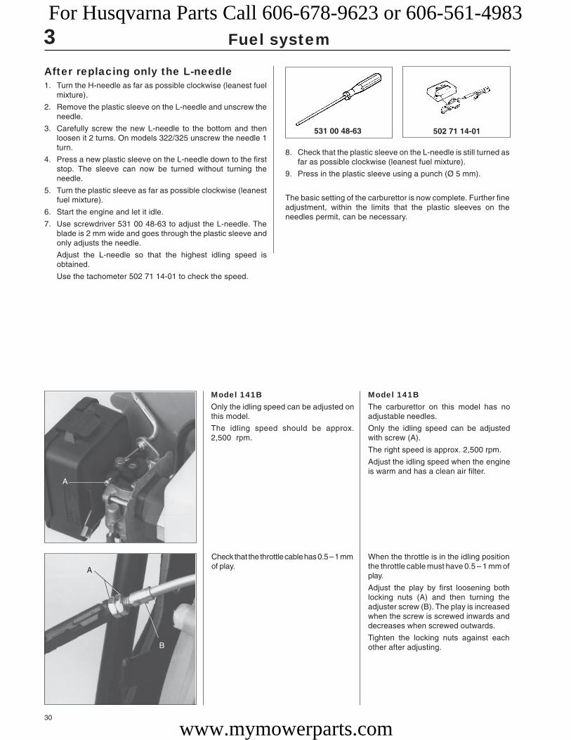
After replacing only the L-needle1. Turn the H-needle as far as possible clockwise (leanest fuel
mixture).
2. Remove the plastic sleeve on the L-needle and unscrew theneedle.
3. Carefully screw the new L-needle to the bottom and thenloosen it 2 turns. On models 322/325 unscrew the needle 1turn.
4. Press a new plastic sleeve on the L-needle down to the firststop. The sleeve can now be turned without turning theneedle.
5. Turn the plastic sleeve as far as possible clockwise (leanestfuel mixture).
6. Start the engine and let it idle.
7. Use screwdriver 531 00 48-63 to adjust the L-needle. Theblade is 2 mm wide and goes through the plastic sleeve andonly adjusts the needle.
Adjust the L-needle so that the highest idling speed isobtained.
Use the tachometer 502 71 14-01 to check the speed.
8. Check that the plastic sleeve on the L-needle is still turned asfar as possible clockwise (leanest fuel mixture).
9. Press in the plastic sleeve using a punch (Ø 5 mm).
The basic setting of the carburettor is now complete. Further fineadjustment, within the limits that the plastic sleeves on theneedles permit, can be necessary.
Model 141BOnly the idling speed can be adjusted onthis model.
The idling speed should be approx.2,500 rpm.
Model 141BThe carburettor on this model has noadjustable needles.
Only the idling speed can be adjustedwith screw (A).
The right speed is approx. 2,500 rpm.
Adjust the idling speed when the engineis warm and has a clean air filter.
Check that the throttle cable has 0.5 – 1 mmof play.
When the throttle is in the idling positionthe throttle cable must have 0.5 – 1 mm ofplay.
Adjust the play by first loosening bothlocking nuts (A) and then turning theadjuster screw (B). The play is increasedwhen the screw is screwed inwards anddecreases when screwed outwards.
Tighten the locking nuts against eachother after adjusting.
For Husqvarna Parts Call 606-678-9623 or 606-561-4983
www.mymowerparts.com

31
3 Fuel system
Mo
de
lO
rde
r n
o.
L1
ca
sin
gL
2 c
ab
leS
eri
al
no
.N
ipp
les
Re
ma
rks
mm
pro
tru
de
mm
250R
– 19
9350
2 27
29-
0110
00 ±
512
0 ±1
Inde
x fin
ger
thro
ttle
502
28 0
6-01
.T
he th
rottl
e ca
ble
runs
und
er th
een
gine
. Ste
el c
asin
g.
250R
1994
–50
2 27
29-
0696
5 ±5
162
±1In
dex
finge
r th
rottl
e 50
2 28
06-
01.
Ste
el c
asin
g on
cab
les
repl
aced
by
502
27 9
3-03
.
250R
– 19
9650
2 27
93-
0396
5 ± 2
152
±1>
6520
029
Inde
x fin
ger
thro
ttle
502
28 0
6-01
.B
row
n Te
flon
casi
ng.
250R
1997
–50
2 27
93-
0464
0 ±2
115
±1>
7180
059
Inde
x fin
ger
thro
ttle
502
28 0
6-01
.B
row
n Te
flon
casi
ng. T
he c
able
runs
thro
ugh
the
cran
kcas
e. R
epla
ced
by 5
37 0
3 71
-02
and
537
02 4
2-02
250R
1998
–53
7 03
71-
0264
0 ±2
115
±1>
8500
001
Inde
x fin
ger
thro
ttle
502
28 0
6-01
.B
lack
pla
stic
cas
ing.
Cab
le Ø
0.9
.K
it w
ith a
ir fil
ter h
olde
r and
rubb
er b
ello
ws.
250R
1998
–53
7 02
42-
0264
0 ±2
115
±1>
8500
001
Inde
x fin
ger
thro
ttle
502
28 0
6-01
.B
lack
pla
stic
cas
ing.
Cab
le Ø
0.9
.
250R
X19
95–
502
27 2
9-07
795
±513
3 ±1
Thu
mb
thro
ttle
502
28 3
7-01
.S
teel
cas
ing
repl
aced
by
502
28 6
0-03
.
250R
X19
96 –
502
28 6
0-03
810
±211
6 ±1
>64
5015
3T
hum
b th
rottl
e 50
2 28
37-
01. B
row
n T
eflo
n ca
sing
.
250R
X–
1997
502
28 6
0-06
810
±211
6 ±1
Thu
mb
thro
ttle
502
28 3
7-01
. Bro
wn
Teflo
n ca
sing
. Cab
le Ø
0.9
.
250R
X19
97 –
502
28 6
0-04
840
± 280
±1
>71
7015
7T
hum
b th
rottl
e 50
2 28
37-
01. B
row
n25
2RX
1997
–Te
flon
casi
ng.
The
cab
le r
uns
thro
ugh
the
cran
kcas
e. R
epla
ced
by 5
02 2
8 60
-05.
250R
X19
97–
502
28 6
0-05
840
±280
±1
>74
2019
0T
hum
b th
rottl
e 50
2 28
37-
01. B
row
n 2
52R
X19
97 –
>74
3000
1Te
flon
casi
ng. T
he c
able
run
s th
roug
hth
e cr
ankc
ase.
Cab
le Ø
0.9
. R
epla
ced
by 5
37 0
3 71
-01
and
537
02 4
2-01
.
252R
X19
98 –
537
03 7
1-01
840
±280
±1
>84
5007
3T
hum
b th
rottl
e 50
2 28
37-
01. B
lack
plas
tic c
asin
g. C
able
Ø 0
.9.
Kit
with
air
filte
r ho
lder
and
rub
ber
bello
ws.
252R
X19
98 –
537
02 4
2-01
840
±280
±1
>84
5007
3T
hum
b th
rottl
e 50
2 28
37-
01. B
lack
plas
tic c
asin
g. C
able
Ø 0
.9.
Th
rott
le c
ab
le
For Husqvarna Parts Call 606-678-9623 or 606-561-4983
www.mymowerparts.com
32
3 Fuel system
Th
rott
le c
ab
le
Mo
de
lO
rde
r n
o.
L1
ca
sin
gL
2 c
ab
leS
eri
al
no
.N
ipp
les
Re
ma
rks
mm
pro
tru
de
mm
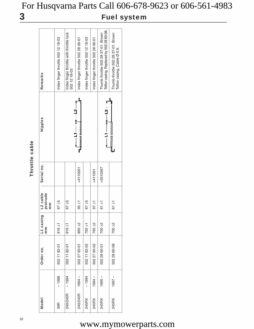
39R
– 19
8850
2 11
82-
0191
6 ±1
67 ±
5In
dex
finge
r th
rottl
e 50
2 12
18-
03
240/
245R
– 19
9450
2 11
82-
0191
6 ±1
67 ±
5In
dex
finge
r th
rottl
e w
ith th
rottl
e lo
ck50
2 12
18-
03
240/
245R
1994
–50
2 27
93-
0189
5 ±2
95 ±
1>
4110
001
Inde
x fin
ger
thro
ttle
502
28 0
6-01
245R
X–
1994
502
11 8
2-02
792
±167
±5
Inde
x fin
ger
thro
ttle
502
12 1
8-03
245R
X19
94 –
502
27 9
3-02
795
±297
±1
>41
1001
Inde
x fin
ger
thro
ttle
502
28 0
6-01
245R
X19
95 –
502
28 6
0-01
700
±261
±1
>55
1026
7T
hum
b th
rottl
e 50
2 28
37-
01. B
row
nTe
flon
casi
ng. R
epla
ced
by 5
02 2
8 60
-08.
245R
X19
97 –
502
28 6
0-08
700
± 261
±1
Thu
mb
thro
ttle
502
28 3
7-01
. Bro
wn
Teflo
n ca
sing
. Cab
le Ø
0.9
.
For Husqvarna Parts Call 606-678-9623 or 606-561-4983
www.mymowerparts.com

33
3
AB
B
C C
C
A
Fuel system
ThrottleModels 322, 325Separate the engine body and the clutchcover.
ThrottleModels 322, 325We recommend that the throttle is dis-mantled from the engine and shaft inorder to efficiently carry out service andrepair work.
Separate the engine body and the clutchcover (see chapter “Ignition system”).
Pull away the shaft with the throttle fromthe clutch cover.
Remove the throttle from the shaft.
Remove both screws (A) (one on eachside).
Loosen the screws (B) and pull off theshaft with the throttle from the clutchcover.
Loosen the 3 fronT-screws (C) (approx. 2turns) holding the throttle halves and pullthe throttle off of the shaft.
Remove the screws holding the throttletogether and carefully separate thehalves.
Note how the different parts are fitted.Pay special attention to which way thereturn spring (A) faces.
The stop contacts can be pried backusing a small screwdriver if they need tobe replaced.
For Husqvarna Parts Call 606-678-9623 or 606-561-4983
www.mymowerparts.com

34
3 Fuel system
Assembly of the throttle is done in thereverse order as set out for dismantling.
Position the parts in the left-hand handlehalf.
Ensure the return spring (A) is facing theright way.
Check that the throttle cable and theshort-circuit cable are pressed correctlydown in their channels so that they arenot pinched when the two handle halvesare screwed together.
Do not forget to put the vibration element(B) in position before the handle halvesare put together. Lubricate the vibrationelement with soapy water. This facilitatesfitting the throttle on the shaft.
Fit together the handle halves using the 5screws, but do not tighten them fully be-fore the throttle has been positioned onthe shaft.
Assemble the remaining parts in the re-verse order as set out for dismantling.
Model 18HRemove the screws and lift off the handlehalf.
Model 18HRemove the screws and note how theywere placed, as they are of differentlengths.
Remove the handle half.
Inspect and replace worn or damagedparts.
Assemble in the reverse order as set outfor dismantling.
Inspect and replace worn or damagedparts.
Assemble in the reverse order as set outfor dismantling.
NOTE! The lever arm for the throttle cabledoes not need to be dismantled.
A B
For Husqvarna Parts Call 606-678-9623 or 606-561-4983
www.mymowerparts.com

35
3 Fuel system
Worn or damaged parts can be easilyreplaced once the right-hand handle halfhas been removed.
Check when assembling that the short-circuit cable is not pinched between thetwo handle halves.
Model 141BRemove the screws and separate thehandle halves.
Model 141BRemove the screws and separate thehandle halves.
NOTE!Check that the fuel hose is notpinched and that the stop contactsits correctly.Fit the throttle cable.
NOTE!Check that the fuel hose is notpinched and that the stop contactsits correctly.Fit the throttle cable.
NOTE!The screw for angling the handledoes not need to be loosened orremoved.
For Husqvarna Parts Call 606-678-9623 or 606-561-4983
www.mymowerparts.com

36
Mondo
122L
Mondo Max
225L/LD
232L
Mondo Mega
225R/RD
232R / 235 R
322
325
240R
245R
250R
245RX
250RX
252RX
265RX
240RBD
235P
250PS
225E
18H
225H60/75
140B
141B
132HBV
225BV/225HBV
3
3,000 9.000 Walbro H = 2 0.48WT 380 L = 2
3,000 10.800 Walbro – 0.40WYL –
3,000 9,000 Walbro H = 2 0.48WT 380 L = 2
2,700 11,000 – Walbro WT 235 H = 1 – 1 1/4 0.5012,000 Walbro WT 270 L = 1 – 1 1/4
2,700 11,000– Walbro WT 235 H = 1 – 1 1/4 0.5012,000 Walbro WT 270 L = 1 – 1 1/4
3,000 9,000 Walbro H = 2 0.46WT 380 L = 2
2,700 11,000– Walbro WT 235 H = 1 – 1 1/4 0.5012,000 Walbro WT 270 L = 1 – 1 1/4
2,700 11,000– Walbro WT 235 H = 1 – 1 1/4 0.5012,000 Walbro WT 270 L = 1 – 1 1/4
2,500 12,500 Zama H = 2 0.50EL 11 L = 1
2,500 12,500 Zama H = 2 0.50EL 11 L = 1
2,700 12,500 Walbro H = 1 – 1 1/4 0.80WT 99 L = 1 – 1 1/4
2,700 12,500 Walbro H = 1 – 1 1/4 0.80WT 99 L = 1 – 1 1/4
2,700 12,500 Walbro HDA 86B H = 1 – 1 1/4 0.80Walbro HDA 142 L = 1 – 1 1/4
2,700 12,500 Walbro H = 1 – 1 1/4 0.80WT 99 L = 1 – 1 1/4
2,700 13,500 Walbro HDA 86B H = 1 – 1 1/4 0.80Walbro HDA 142 L = 1 – 1 1/4
2,700 14,000 Walbro H = 1 – 1 1/4 0.80HDA 142 L = 1 – 1 1/4
2,250 11,500 Tillotson H = 1 – 1 1/4 1.00HS 121A L = 1 – 1 1/4
2,700 11,000– Walbro WT 235 H = 1 – 1 1/4 0.6012,000 Walbro WT 270 L = 1 – 1 1/4
2,700 – Walbro WT 235 H = 3/4 – 1 0.50Walbro WT 270 L = 3/4 – 1
2,500 11,500 Walbro HDA 86B H = 1 – 1 1/4 0.90Walbro HDA 142 L = 1 – 1 1/4
2,700 11,000– Walbro H = 1 – 1 1/4 0.5012,000 WT 270 L = 1 – 1 1/4
3,000 10,000 Walbro WT 379 H = 2 0.21Zama CIU-W4 L = 2
2,700 11,000– Walbro WT 406 H = 1 – 1 1/4 0.4012,000 Walbro WT 421 L = 1 – 1 1/4
2,500 Walbro HDA 110A H = 1 2.0L = 1
2,500 Walbro WYK – 2.0
2,500 7,600 Walbro 0.60WT 141
2,500 8,200 Walbro WT 235 H = 1 – 1 1/4 0.40Walbro WT 270 L = 1 – 1 1/4
Fuel systemTechnical data
Model Idling speed Max. speed Carburettor type Tank volumerpm rpm ◊ type setting * fuel, litre
* Only basic setting. Applies to carburettor needles without plastic caps fitted.◊ Do not exceed the stated max speed. Risk of engine damage. The figures apply to a run-in engine. Reduce the speed by 600 – 700 rpm for an engine that has not been run-in.
For Husqvarna Parts Call 606-678-9623 or 606-561-4983
www.mymowerparts.com

37
4.Centrifugal clutch
ContentsClutch and clutch drum
Model 250PS _____________________________ 38
Models 240/245 ___________________________ 38
Models 225 AI15, 225 AI25 __________________ 39
Models 322/325 ___________________________ 39
Model 322C ______________________________ 40
Model 18H _______________________________ 41
Technical data _____________________________ 43
For Husqvarna Parts Call 606-678-9623 or 606-561-4983
www.mymowerparts.com

38
4
504 91 06-05
502 52 16-01 502 52 14-01
A
B
Centrifugal clutch
ClutchModel 250PSUnscrew the cable clamp (A) and thehose clamp (B).
Turn the hydraulic oil tank clockwise andpull it off from the engine body.
ClutchModel 250PSThe clutch on this model is positionedbetween the engine body and the hydrau-lic unit.
1. Unscrew the clamp (A) holding thecontrol cable on the hydraulic oil tank.
2. Loosen the hose clamp (B).
3. Turn the hydraulic oil tank clockwiseand pull it off from the engine body.(Bayonet fitting).
Remove the clutch nut and dismantle theclutch according to the instructions formodel 250.
Dismantle the cylinder cover and replacethe spark plug with piston stop no. 504 9106-05.
Remove the clutch nut by turning it anti-clockwise.
Dismantle the clutch from the crankshaftand carry out an inspection and servicingas set out in the instructions for model250.
Clutch drumModel 250PSDismantle the clutch drum from the hy-draulic unit’s axle
Clutch drumModel 250PSThe clutch drum is screwed onto thehydraulic unit’s axle.
Dismantle the drum by using the holdingtool 502 52 16-01 and allen key502 52 14-01.
ClutchModels 240/245Separate the engine body and tank unit.
Unscrew the screws on the clutch hous-ing and remove shaft unit.
ClutchModels 240/245Separate the engine body and tank unitin the same way as described for model250.
Remove the screws holding the clutchhousing on the engine body and lift off theentire shaft unit.
The clutch can be one of two different designs. Firstly, a three shoe clutch of the sametype as used on model 235. See this model for service measures. This clutch wasintroduced from the following serial numbers:
Model 240R no. 82 00 059, model 245R no. 81 70.180, model 245RX no. 81 60 227.
Secondly, the clutch can be a two shoe model as described in the workshop manual.
Replace the clutch drum if the inner di-ameter exceeds 70.0 mm.
NOTE!
Turn the allen key clockwise.
For Husqvarna Parts Call 606-678-9623 or 606-561-4983
www.mymowerparts.com
39
4 Centrifugal clutch
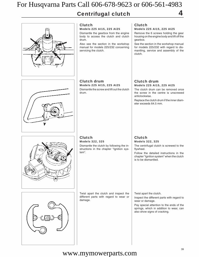
Twist apart the clutch and inspect thedifferent parts with regard to wear ordamage.
Twist apart the clutch.
Inspect the different parts with regard towear or damage.
Pay special attention to the ends of thesprings, which in addition to wear, canalso show signs of cracking.
ClutchModels 322, 325Dismantle the clutch by following the in-structions in the chapter “Ignition sys-tem”.
ClutchModels 322, 325The centrifugal clutch is screwed to theflywheel.
Follow the detailed instructions in thechapter “Ignition system” when the clutchis to be dismantled.
Clutch drumModels 225 AI15, 225 AI25Dismantle the screw and lift out the clutchdrum.
Clutch drumModels 225 AI15, 225 AI25The clutch drum can be removed oncethe screw in the centre is unscrewedanticlockwise.
Replace the clutch drum if the inner diam-eter exceeds 64.5 mm.
ClutchModels 225 AI15, 225 AI25Dismantle the gearbox from the enginebody to access the clutch and clutchdrum.
Also see the section in the workshopmanual for models 225/232 concerningservicing the clutch.
ClutchModels 225 AI15, 225 AI25Remove the 6 screws holding the gearhousing on the engine body and lift off thegearbox.
See the section in the workshop manualfor models 225/232 with regard to dis-mantling, service and assembly of theclutch.
For Husqvarna Parts Call 606-678-9623 or 606-561-4983
www.mymowerparts.com
40
502 52 16-01
4 Centrifugal clutch
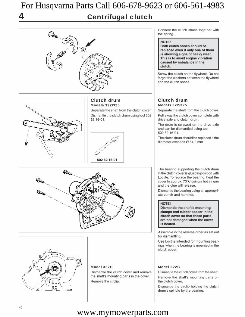
Connect the clutch shoes together withthe spring.
Clutch drumModels 322/325Separate the shaft from the clutch cover.
Pull away the clutch cover complete withdrive axle and clutch drum.
The drum is screwed on the drive axleand can be dismantled using tool502 52 16-01.
The clutch drum should be replaced if thediameter exceeds Ø 64.0 mm
The bearing supporting the clutch drumin the clutch cover is glued in position withLoctite. To replace the bearing, heat thecover to approx. 70°C using a hot air gunand the glue will release.
Dismantle the bearing using an appropri-ate punch and hammer.
Model 322CDismantle the clutch cover and removethe shaft’s mounting parts in the cover.
Remove the circlip.
Model 322CDismantle the clutch cover from the shaft.
Remove the shaft’s mounting parts onthe clutch cover.
Dismantle the circlip holding the clutchdrum’s spindle by the bearing.
Assemble in the reverse order as set outfor dismantling.
Use Loctite intended for mounting bear-ings when the bearing is mounted in theclutch cover.
NOTE!Dismantle the shaft’s mountingclamps and rubber spacer in theclutch cover so that these partsare not damaged when the coveris heated.
Screw the clutch on the flywheel. Do notforget the washers between the flywheeland the clutch shoes.
NOTE!Both clutch shoes should bereplaced even if only one of themis showing signs of heavy wear.This is to avoid engine vibrationcaused by imbalance in theclutch.
Clutch drumModels 322/325Separate the shaft from the clutch cover.
Dismantle the clutch drum using tool 50252 16-01.
For Husqvarna Parts Call 606-678-9623 or 606-561-4983
www.mymowerparts.com

41
4
504 91 06-05
Centrifugal clutch
Dismantle the clutch and inspect the partswith regard to damage or wear. Replacerequisite parts and assemble in the re-verse order as set out for dismantling.
Dismantle the clutch by prying out thesprings with a small screwdriver.
Inspect the clutch with regard to damageand wear.
Dismantle the clutch using an appropri-ate punch and hammer.
Dismantle the clutch from the crankshaftusing an appropriate punch and hammer.
If the clutch is sitting extremely tight andthe compression force is not sufficient asa stop, the spark plug can be replaced bythe piston stop no 504 91 06-05.
ClutchModel 18HRemove the 4 screws and move the cut-ting equipment to one side.
ClutchModel 18HThe cutting equipment must be disman-tled from the engine body to access theclutch.
Remove the 4 screws and move the cut-ting equipment to one side.
Press off the clutch drum.
Replace the bearing and fit the remainingparts in the reverse order as set out fordismantling.
Now press out the clutch drum using asuitable punch and hammer.
The bearing is replaced in the same wayas described above.
Assemble in the reverse order as set outfor dismantling.
Assemble the clutch in the reverse orderas set out for dismantling.
NOTE!Both clutch shoes should bereplaced at the same time toprevent imbalance.
For Husqvarna Parts Call 606-678-9623 or 606-561-4983
www.mymowerparts.com

42
4 Centrifugal clutch
Clutch drumModel 18HSee chapter “Attachments”.
Clutch drumModel 18HSee chapter “Attachments”.
For Husqvarna Parts Call 606-678-9623 or 606-561-4983
www.mymowerparts.com

43
Mondo
122L
Mondo Max
225L/LD
232L
Mondo Mega
225R/RD
232R
322
325
235R
240R
245R
250R
245RX
250RX
252RX
265RX
240RBD
235P
250PS
225E
18H
225H60/75
225AI15, 225AI25
4,000 – –
3,900 Ø 58.0 Min. 0.5 mm of lining remaining
4,000 – –
3,700 Ø 64.5 Max 1 mm wear per shoe
3,800 Ø 64.5 Max 1 mm wear per shoe
4,000 – –
3,700 Ø 64.5 Max 1 mm wear per shoe
3,800 Ø 64.5 Max 1 mm wear per shoe
3,800 Ø 64.0 Max 1 mm wear per shoe
3,800 Ø 64.0 Max 1 mm wear per shoe
3,800 Ø 64.5 Max 1 mm wear per shoe
3,700 Ø 65.0 Max 1 mm wear per shoe
3,700 Ø 65.0 Max 1 mm wear per shoe
4,300 Ø 70.0 Max 1 mm wear per shoe
3,700 Ø 65.0 Max 1 mm wear per shoe
4,300 Ø 70.0 Max 1 mm wear per shoe
4,300 Ø 70.0 Max 1 mm wear per shoe
3,500 Ø 80.0 Max 1 mm wear per shoe
3,600 Ø 64.5 Max 1 mm wear per shoe
3,900 Ø 64.5 Max 1 mm wear per shoe
4,300 Ø 70.0 Max 1 mm wear per shoe
3,700 Ø 64.5 Max 1 mm wear per shoe
4,600 – –
5,400 Ø 64.5 Max 1 mm wear per shoe
5,400 Ø 64.5 Max 1 mm wear per shoe
4Technical data
Model Engage speed Wear limit Wear limitrpm clutch drum clutch shoe
Centrifugal clutch
For Husqvarna Parts Call 606-678-9623 or 606-561-4983
www.mymowerparts.com

44
For Husqvarna Parts Call 606-678-9623 or 606-561-4983
www.mymowerparts.com

45
Angle gear
5.
ContentsAssembling model 265 ______________________ 46
Dismantling, assembling, models 250, 240/245 __ 46
Dismantling, assembling, models 322/325_______ 48
Assembly ________________________________ 49
Technical data _____________________________ 50
For Husqvarna Parts Call 606-678-9623 or 606-561-4983
www.mymowerparts.com

46
5
Model 265
1.
2.3.
Model 265
from serial no. > 64 90 191
A
A
21.5 mm
Angle gear
AssemblyModel 265Fit the bearings on respective axles. It iseasier if the bearing is heated to approx.100°C.
Dismantling, assemblingModels 250, 240/245Remove the cover, O-ring and washer.
Dismantling, assemblingModels 250, 240/245Remove the 3 screws holding the cover.
Lift off the cover, O-ring (240/245) andthe washer that lies against the bearing.
Heat the gear housing to approx. 150°Cand first lift the output axle in positionand then the input axle.
Make sure the bearing bottoms in itsseating.
The parts (A) are only supplied withspare part gears. This is so the gears canbe fitted on the old 165R where driveaxle also had a spline on the clutch drum.
The parts (A) prevent the drive axle fromsliding down through the pinion geartowards the gear on the blade axle.Mounted inside the pinion gear axle.
In those cases the drive axle is threadedby the clutch drum these parts are notrequired.
From serial number 64 90 191 the sealingring has been removed and replacedwith the three parts listed below.
1. Steel spacer2. Aluminium ring3. O-ring
The operating temperature falls consid-erably when the sealing ring is removedand is replaced by the new components.In addition, the steel spacer prevents theblade axle from shifting upwards, e.g.with impact from below.
On later models of the angle gear (fromserial number 62 60 067) another type ofdrive disc has been fitted to prevent grassand dirt from penetrating into the anglegear and destroying the sealing ring.The new drive disc has order no.502 25 41-02.
It can be fitted to angle gears that havecover with order no. 502 10 72-02 and502 10 72-03. The centre hole in thecover is Ø 22 mm.
NOTE! Do not forget the circlip holding thebearing on the input axle.
For Husqvarna Parts Call 606-678-9623 or 606-561-4983
www.mymowerparts.com

47
5
502 52 17-01
502 50 65-01
Model 250
Model 250
Serial no. > 710 00 065 (250RX)
Serial no. > 710 00 122 (250R)
A
B
Models 240, 245
Angle gear
Heat the gearbox and dismantle the in-put and output axles in the same way asdescribed for model 265.
Unscrew the ring nut holding the inputaxle in position by using tool no.502 52 17-01.
Unscrew the ring nut.
NOTE! On the new angle gear design formodels 240/245 the sealing ring (B)has been replaced by an O-ring,aluminium ring and a steel spacer.
NOTE!The input axle with pinion must bedismantled first. Use puller502 50 65-01 when the output axleis dismantled.
Replace damaged parts.
Assemble the angle gear in the reverseorder as set out for dismantling.
Fit the bearings on respective axles. It iseasier if the bearing is heated to approx.100°C.
NOTE!Do not forget the circlip holding thebearing on the input axle. Makesure the bearing bottoms in itsseating.
Heat the gear housing to approx. 150°Cand first lift the output axle in positionand then the input axle. Make sure thebearing bottoms in its seating.
NOTE!The sealing ring on later modelshas been replaced by an O-ringand an aluminium sleeve (A).
For Husqvarna Parts Call 606-678-9623 or 606-561-4983
www.mymowerparts.com

48
5
502 52 15-01
503 97 64-01
Models 240, 245
C
•
A
Angle gear
The operating temperature in the anglegear falls considerably when the sealingring is removed and replaced by the newcomponents (C). In addition, the steelspacer prevents the blade from shiftingupwards, e.g. with impact from below.
Check and possibly replace the sealingring and O-ring (A) at the ends of theshaft.
Check that the sealing ring and O-ring(A), at the end of the shaft, are undamagedbefore the gear is fitted.
Do not forget to fill the gear housing 3/4full with special grease 503 97 64-01.
Dismantling/assemblingModels 322/325Remove the angle gear from the shaft.
Remove the circlips holding the bearingson the input respective output axles.
Dismantling/assemblingModels 322/3251. Remove the cutting equipment and
guard.
2. Loosen the screw holding the anglegear on the shaft and remove theangle gear.
3. Remove the circlips holding the bear-ings on the output axle (illustrated)and on the input axle using the circlippliers.
NOTE!Use centre punch no. 502 52 15-01to centre the cover on thegearbox.Use Loctite on the screws.
WARNING! Too much grease canmean that it will be pressedpast the sealing rings. Thetemperature in the trans-mission can also be toohigh.
!
From date code 96391 on the gearbox
Fit the cover.
For Husqvarna Parts Call 606-678-9623 or 606-561-4983
www.mymowerparts.com

49
5
A
B
C
D
Angle gear
Heat the entire angle gear using a hotair gun to approx. 110°C.
Knock the gear against a wooden blockso that the input axle and the bearing fallout.
Now lift out the output axle.
Wear protective gloves
AssemblyClean all component parts and replace ifdamaged or worn.
Fit the bearings on respective axles. Thisis easier if the bearings are heated toapprox. 110°C using a hot air gun.
Heat the entire angle gear to approx.110°C and first dismantle the input axleand then the output axle.
NOTE!Do not forget to fill the gearhousing to approx. 3/4 with gearhousing grease 503 97 64-01 oncethe plug (D) has been removed.
Heat the gearbox to approx. 110°C andfirst place the output axle in position andthen the input axle.
Make sure the bearing bottoms in itsseating.
Fit the circlips (B) and (C). Make surethey lie correctly in their grooves.
Assemble remaining parts in the reverseorder as set out for dismantling.
NOTE!Do not forget the circlip (A)holding the bearing on the inputaxle.
For Husqvarna Parts Call 606-678-9623 or 606-561-4983
www.mymowerparts.com

50
5
M ndo
122L
Mondo Max
225L/LD
232L
Mondo Mega
225R/RD
232R
322
325
235R
240R
245R
250R
245RX
250RX
252RX
265RX
240RBD
235P
250PS
225E
18H
225H60/75
140B, 141B
132HBV
225BV/225HBV
1:1 3/8"x24(R) – – 30° 9,000
1:1.33 M10x1.25 – – 35° 8,100
1:1.23 3/8"x24(L) – – 30° 7,300
1:1.40 M10x1.25 – – 35° 8,500
1:1.40 M10x1.25 _ _ 35° 8,500
1:1.33 3/8"x24(L) 20.0 200 30° 7,300
1:1.40 M10x1.25 20.0 200–255 35° 8,500
1:1.40 M10x1.25 20.0 200–275 35° 8,500
1:1.46 M10x1.25 25.4 200–255 30° 8,560
1:1.46 M10x1.25 25.4 200–255 30° 8,560
1:1.53 M12x1.75 20.0 200–300 35° 7,800
1:1.36 M12x1.75 20.0 200–300 30° 9,190
1:1.36 M12x1.75 20.0 200–300 30° 9,190
1:1.36 M12x1.75 20.0 200–300 30° 9,190
1:1.36 M12x1.75 20.0 200–300 30° 9,190
1:1.36 M12x1.75 20.0 200–300 30° 9,930
1:1.36 M12x1.75 20.0 200–300 30° 10,300
1:1.26 M12x1.75 20.0 200–300 25° 9,120
1:1.40 M10x1.25 20.0 200–300 35° 7,800
– – – – – –
– – – – – –
1:1.40 M10x1.25 25.4 – 35° 8,500
1:5.7 – – – – –
1:7.25 – – – – –
– – – – – –
– – – – – –
– – – – – –
Angle gearTechnical data
Model Gear Axle thread Blade hole Blade diameter Angle Max. axle speedratio diameter mm degrees rpm
mm
For Husqvarna Parts Call 606-678-9623 or 606-561-4983
www.mymowerparts.com

51
ContentsDismantling, cleaning, inspection, assembly, models 322/325 _______ 52
Dismantling, cleaning, inspection, assembly, model 18H ___________ 53
Dismantling, cleaning, inspection, assembly, models 140B, 141B ____ 55
Analysis and measures _____________________________________ 56
Service tips _______________________________________________ 61
Wear limits _______________________________________________ 61
Technical data _____________________________________________ 62
Cylinder and piston
6.
For Husqvarna Parts Call 606-678-9623 or 606-561-4983
www.mymowerparts.com
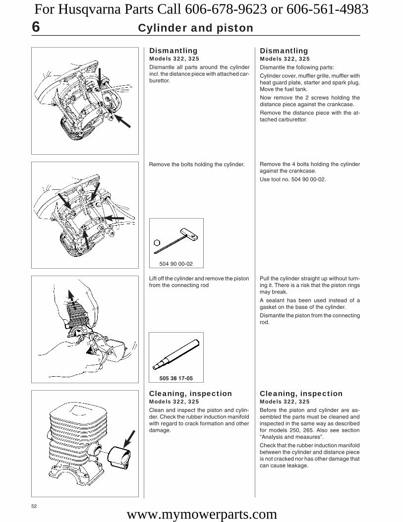
52
Cylinder and piston
DismantlingModels 322, 325Dismantle all parts around the cylinderincl. the distance piece with attached car-burettor.
DismantlingModels 322, 325Dismantle the following parts:
Cylinder cover, muffler grille, muffler withheat guard plate, starter and spark plug.Move the fuel tank.
Now remove the 2 screws holding thedistance piece against the crankcase.
Remove the distance piece with the at-tached carburettor.
Remove the bolts holding the cylinder. Remove the 4 bolts holding the cylinderagainst the crankcase.
Use tool no. 504 90 00-02.
Lift off the cylinder and remove the pistonfrom the connecting rod
Pull the cylinder straight up without turn-ing it. There is a risk that the piston ringsmay break.
A sealant has been used instead of agasket on the base of the cylinder.
Dismantle the piston from the connectingrod.
Cleaning, inspectionModels 322, 325Clean and inspect the piston and cylin-der. Check the rubber induction manifoldwith regard to crack formation and otherdamage.
Cleaning, inspectionModels 322, 325Before the piston and cylinder are as-sembled the parts must be cleaned andinspected in the same way as describedfor models 250, 265. Also see section“Analysis and measures”.
Check that the rubber induction manifoldbetween the cylinder and distance pieceis not cracked nor has other damage thatcan cause leakage.
505 38 17-05
6
504 90 00-02
For Husqvarna Parts Call 606-678-9623 or 606-561-4983
www.mymowerparts.com

53
Cylinder and piston
DismantlingModel 18HDismantle the spark plug and cylindercover.
Remove the air filter cover and air filter.
Loosen the two screws holding the airfilter holder and carburettor.
Now lift off the carburettor.
DismantlingModel 18HDismantle the spark plug, cylinder coverand carburettor.
Lubricate the piston using a few drops ofoil and carefully slide the cylinder over thepiston.
Carefully slide the cylinder over the pis-ton and tighten the 4 bolts crosswise.
Clean any sealant and grease from thecontact surface on the base of the cylin-der.
Apply a narrow bead (1–1.5 mm) of seal-ant no. 503 26 70-01 on the contact sur-face.
Clean the contact surface at the base ofthe cylinder and apply a narrow bead ofsealant no. 503 26 70-01 on the contactsurface.
AssemblyModels 322, 325Clean any sealant and grease from thecrankcase.
Fit the piston on the connecting rod sothat the arrow on the piston points to-wards the exhaust port.
AssemblyModels 322, 325Clean the sealant from the crankcase andassemble the piston on the connectingrod.
NOTE!Also apply sealant to the bearingseatings in the crankcase andcylinder if the old bearings are tobe refitted.No sealant is required if newbearings are fitted.
NOTE!Do not turn the cylinder, as thepiston ring can easily be broken.
Tighten the 4 bolts crosswise.
Assemble the remaining parts in the re-verse order as set out for dismantling.
6
503 26 70-01
For Husqvarna Parts Call 606-678-9623 or 606-561-4983
www.mymowerparts.com

54
Cylinder and piston
Dismantle the carburettor’s distance piecefrom the cylinder.
Remove both screws holding the carbu-rettor’s distance piece on the cylinder.
Carefully pry off the distance piece usinga screwdriver.
Dismantle one of the springs holding themuffler.
Pry off one of the springs holding themuffler by using a small screwdriver.
Move the muffler away, but let it remainsuspended by the rear spring.
Dismantle the cylinder and connectingrod and piston.
Remove the 2 screws holding the cylinderwith an allen key (3/16") no 502 50 57-01.
Lift off the cylinder with the muffler.
Remove the cover on the crankcase andlift off the piston and connecting rod.
Cleaning, inspectionand assemblyModel 18HPerformed in the same way as describedfor model Mondo.
Cleaning, inspectionand assemblyModel 18HPerformed in the same way as describedfor model Mondo. (See Workshop Manual).
NOTE!Hook the muffler in the rearspring before the cylinder isfitted. This facilitates assembly.
502 50 57-01
6For Husqvarna Parts Call 606-678-9623 or 606-561-4983
www.mymowerparts.com

55
Cylinder and piston
DismantlingModels 140B, 141BRemove the spark plug.
Unscrew the 3 screws and lift off thecover.
Loosen the screws and lift off the cylin-der.
Loosen the 4 screws holding the cylinderagainst the crankcase.
Lift off the cylinder straight upwards sothat the piston rings are not broken.
Dismantle the piston in the same way asdescribed for models 250, 265 in theWorkshop Manual.
Dismantle the carburettor and throttlecable holder from the distance piece.
Dismantle the air filter, throttle cable holderand carburettor according to the instruc-tions in the chapter
Remove the cooling air plate and disman-tle the muffler.
Lift off the cooling air plate above thecylinder.
Dismantle the muffler by removing the2 screws.
DismantlingModels 140B, 141BDismantle the cylinder cover.
6
502 50 22-01
502 50 23-01
504 90 00-03
For Husqvarna Parts Call 606-678-9623 or 606-561-4983
www.mymowerparts.com

56
New piston. Exhaust side.New piston. Inlet side.
Small to medium sized scores primarily inthe middle of the exhaust port.
Cylinder and piston
Cleaning, inspectionModels 140B, 141BClean and inspect the different cylinderand piston parts.
Cleaning, inspectionModels 140B, 141BClean and inspect the cylinder, piston,piston rings and gudgeon pin in the sameway as described for models 250, 265 inthe Workshop Manual. Also see section“Analysis and measures”.
Scrape off any gasket residue from thebase of the cylinder and crankcase aswell as the contact surfaces for the dis-tance piece on the carburettor side.
AssemblyModels 140B, 141BAssembly takes place in the same way asdescribed for model 122.
AssemblyModels 140B, 141BAssembly takes place in the same way asdescribed for model 122. (See WorkshopManual).
Analysis and measuresThe two pictures to the left show what anew piston looks like, one on the inletside the other on the exhaust side. Notethat the machining marks from manufac-turing are clearly visible.
Use these pictures as a reference whendetermining damage and wear.
Experience tells us that piston or cylin-der failures due to manufacturing errorsare extremely rare.
The reason is usually due to other fac-tors, which is evident from the following.
Note the reasons for the breakdown, re-pair the damage and take the actions toprevent the same thing happening again.
Insufficient lubricationThe piston has small to medium size score marks usually in front of the exhaust port.In extreme case heat development can be so great that material from the piston smearsalong the piston skirt and even in the cylinder bore.
Generally the piston ring is undamaged and moves freely in the ring groove
There can also be scores on the inlet side of the piston.
Reason:● Incorrect carburettor setting. Recom-
mended max. speed exceeded.
● Incorrect oil mixture in the fuel.
● Fuel has too low octane value.
Action:Check and change the carburettor set-ting.
Change the fuel.
Change to a higher octane petrol.
NOTE!If the piston has been dismantledfrom the connecting rod it isassembled so that the locking pincomes towards the exhaust port.Use assembly kit no. 504 90 00-03and tool 502 50 70-01 when thecylinder is fitted on the crankcase.Assemble remaining parts in thereverse order.
NOTE!If the piston is to be dismantledfrom the connecting rod, theengine must first be dismantledfrom the fan so that one ofgudgeon pin’s circlips can beremoved.See chapter “Ignition system”.
504 90 00-03 502 50 70-01
6For Husqvarna Parts Call 606-678-9623 or 606-561-4983
www.mymowerparts.com

57
Cylinder and piston
The piston ring starts to stick or is completely stuck in its groove and has therefore notbeen able to seal against the cylinder wall, which has resulted in further, intensivetemperature increases on the piston
Seizure scores along the entire piston skirt on the inlet and exhaust sides.
Reason:● Incorrect oil mixture in the fuel.
● Fuel has too low octane value.
● Air leaks.
Cracked fuel pipe.
Leaking inlet gaskets.
Cracked manifold or inlet manifold.
● Air leakage in engine body.
Leaking crankshaft seals.
Leaking cylinder and crankcasegaskets.
● Bad maintenance.
Dirty cooling fins on the cylinder.
Blocked air intake on the starter.
Blocked spark arrest screen on themuffler.
Action:Change to a fuel with the correct oil mixture.
Change to a higher octane petrol.
Replace damaged parts.
Replace leaking gaskets and shaft seals.
Clean the cooling fins and air intake.
Clean or replace the spark arrest screen.
Medium to deep scores on the exhaust side.The piston ring is stuck in the groove.Black discoloration under the piston ringdue to blow-by.
Medium to deep scores along the entirepiston skirt on the exhaust side.
Heavy scoring along the entire piston skirton the exhaust side.
Piston scoring caused by heavy carbon depositsToo heavy carbon depositing can cause damage similar to that caused by insufficientlubrication. However, the piston skirt has a darker colour caused by the hot combustiongases that are blown past the piston.
This type of piston damage starts at the exhaust port where carbon deposits canbecome loose and trapped between the piston and cylinder wall.
For the best results we recommend Husqvarna two-stroke oil, which is speciallydeveloped for air-cooled two-stroke engines.
Mixing ratio: 1:50 (2%).
If Husqvarna two-stroke oil is not available another good quality two-stroke oil can beused.
Mixing ratio: 1:33 (3%) or 1:25 (4%).
6For Husqvarna Parts Call 606-678-9623 or 606-561-4983
www.mymowerparts.com

58
Cylinder and piston
Inlet side. The piston ring is stuck in thegroove. Black discoloration under the pistonring due to blow-by.
Exhaust side damaged by a broken pistonring. The piston ring parts damage the topsection and cause score marks.
Typical for this type of piston damage is brown or black discoloration of the piston skirt.
Cause:● Wrong type of two-stroke oil or petrol.
● Incorrect oil mixture in the fuel.
● Incorrect carburettor setting.
Action:Change the fuel.Change to a fuel with the correct oil mix-ture.
Correct the carburettor setting
Piston damage caused by a too high engine speedTypical damage associated with a too high engine speed is broken piston rings, brokencirclips on the gudgeon pin, faulty bearings or that the guide pin for the piston ring hasbecome loose.
Piston ring breakageA too “lean” carburettor setting results in a too high speed and a high pistontemperature. If the piston temperature rises above the normal working temperature thepiston ring can seize in its groove, consequently it will not sit deep enough in its groove.The edges of the piston ring can then hit the top edge of the exhaust port and besmashed and also cause piston damage.
A too high engine speed can also cause rapid wear to the piston ring and play in thepiston ring groove primarily in front of the exhaust port. The ring is weakened by thewear and can be caught in the port causing serious piston damage.
6For Husqvarna Parts Call 606-678-9623 or 606-561-4983
www.mymowerparts.com

59
Cylinder and piston
The guide pin for the piston ring has beenpushed up through the top of piston.
Irregular grooves on the piston’s inlet sidecaused by a broken roller retainer.
Deep, irregular grooves caused by a loosecirclip. Shown here on the piston’s inlet side.
Bearing failureA failure on the crankshaft bearing or on theconnecting rod bearing is usually caused bya too high engine speed, resulting in thebearing being overloaded or over heating.This in turn can cause the bearing rollers orball to glide instead of rotate, which canmean the roller or ball retainer breaks.
The broken debris can be trapped betweenthe piston and cylinder wall, damaging thepiston skirt.
Debris can also pass up through the cylin-der’s transfer channels and cause damageto the top and sides of the piston as well asthe cylinder’s combustion chamber.
Small score marks and a matt, grey surfaceon the piston’s inlet side caused by fine dustparticles.
Piston ring guide pinvibrated looseA too high engine speed can cause theends of the piston ring to hammer againstthe guide pin when the piston ring moves inits groove. The intensive hammering candrive out the pin through the top of thepiston causing serious damage also to thecylinder.
Damage caused bygudgeon pin circlipsA too high engine speed can cause thegudgeon pin circlips to vibrate. The circlipsare drawn out of their groove due to thevibrations, which in turn reduces the circlips’tensioning power. The rings can then be-come loose and damage the piston.
Foreign objectsEverything other than clean air and pure fuel that enters the engine’s inlet port causessome type of abnormal wear or damage to the cylinder and piston.
This type of increased wear shows on the piston’s inlet side starting at the lower edge ofthe piston skirt.
The damage is caused by badly filtered air that passes through the carburettor and intothe engine.
6For Husqvarna Parts Call 606-678-9623 or 606-561-4983
www.mymowerparts.com

60
Cylinder and piston
Inlet side.
Particles of dust and dirt from carbon-likedeposits on the top of the piston and in thepiston ring groove. The piston ring sits firmlyin the groove. Piston material has been wornaway.
The lower part of the piston skirt is thinner onthe inlet side than on the exhaust side.
The piston scored and worn from the pistonring down on the inlet side.
Extensive damage to the lower part of thepiston’s inlet side.
Cause:● Faulty air filter. Small dust particles
pass through the filter.
● The filter is worn out due to too muchcleaning, whereby small holes haveappeared in the material.
● Unsuitable filter maintenance, e.g.wrong method or wrong cleaningagent. Flock material becomes looseand holes appear.
● Air filter incorrectly fitted.
● Air filter damaged or missing.
Action:Fit a finer grade filter.
Check the filter carefully for holes anddamage after cleaning. Replace the filterif necessary.
Clean more carefully and use the rightcleaning agent (e.g. tepid soapy water orHusqvarna Active Cleaning).Change the filter.
Fit the filter correctly.
Fit a new air filter.
Large, softer particles that penetrate into the engine cause damage to the piston skirtunder the piston ring as the photograph shows.
Cause:● Air filter incorrectly fitted.
● Air filter damaged or missing.
Action:Fit the air filter correctly.
Fit a new air filter.
Larger, harder particles that enter the engine cause serious damage to the undersideof the piston skirt.
Cause:● Air filter damaged or missing.
● Parts from the carburettor or intakesystem have become loose and enteredthe engine.
Action:Fit a new air filter.
Regular service and inspection.
6
505 69 85-70
For Husqvarna Parts Call 606-678-9623 or 606-561-4983
www.mymowerparts.com

61
Cylinder and piston
Max. 0.15 mm. Clean the groovecarefully before measuring.
When the surface coating isworn and aluminium appears.
Max. 1.0 mm with the pistonring inserted in the lower part ofthe cylinder.
Max. height on a new pistonring + 0.10 mm.
Wear tolerancesCylinder bore Piston ring gap Piston ring groove Piston ring play
Service tips
Defect:Broken cooling fins, damaged threads or sheared bolts bythe exhaust port.
Seizure marks in the cylinder bore (especially by the exhaustport).
Surface coating in the cylinder bore worn out (primarily at thetop of the cylinder).
The piston shows signs of seizure score marks.
Piston ring burnt in its groove.
Action:In bad situations – replace the cylinder.Repair the threads using Heli-Coil.
Polish the damaged area using a fine grade emery cloth sothat the coating of aluminium disappears.With deep seizure score marks the piston and cylindershould be replaced.
Replace the cylinder and piston.
Carefully polish the damaged area using a fine file or finegrade emery cloth. Before the piston is refitted the cylindershould be polished as above. With deep score marks thepiston and cylinder should be replaced.
Carefully loosen the piston rings and clean the groove wellbefore refitting. Carbon deposits in the groove impair theimportant heat transfer between the piston and cylinder.
Check the wear on the piston ring by placing it in the lowerpart of the cylinder.
6For Husqvarna Parts Call 606-678-9623 or 606-561-4983
www.mymowerparts.com

62
Cylinder and piston
Technical data
Model Displacement Cylinder diameter Stroke lengthcm3 mm mm
6
Mondo
122L
Mondo Max
225L/LD
232L
Mondo Mega
225R/RD
232R
322
325
235R
240R
245R
250R
245RX
250RX
252RX
265RX
240RBD
235P
250PS
225E
18H
225H60/75
140B, 141B
132HBV
225BV/225HBV
24.0 34.5 26.4
22.5 32.0 28.0
24.0 34.5 26.4
25.4 34.0 28.0
30.8 35.0 32.0
24.0 34.5 26.4
25.4 34.0 28.0
30.8 35.0 32.0
21.7 32.0 27.0
24.5 34.0 27.0
36.3 38.0 32.0
40.2 40.0 32.0
44.3 42.0 32.0
48.7 44.0 32.0
44.3 42.0 32.0
48.7 44.0 32.0
50.8 45.0 32.0
65.1 48.0 36.0
36.3 38.0 32.0
36.3 38.0 32.0
48.7 44.0 32.0
25.4 34.0 28.0
18.0 29.5 26.4
25.4 34.0 28.0
40.2 40.0 32.0
31.7 36.9 30.2
25.4 34.0 28.0
For Husqvarna Parts Call 606-678-9623 or 606-561-4983
www.mymowerparts.com
63
7.Crankshaft and crankcase
ContentsReplacing the sealing ring ignition side
Model 250PS ____________________________________ 64
Replacing the sealing ring clutch side
Model 250PS ____________________________________ 64
Assembling the crankcase
Model 250PS ____________________________________ 64
Dismantling/assembling the crankshaft
Model 225HBV ___________________________________ 65
Models 225AI15, 225AI25 __________________________ 66
Models 322, 325 __________________________________ 67
Dismantling/Assembling the crankcase
Model 18H ______________________________________ 67
Models 140B, 141B _______________________________ 69
Leakage testing the crankcase _____________________ 70
Husqvarna E-TECH _______________________________ 71
For Husqvarna Parts Call 606-678-9623 or 606-561-4983
www.mymowerparts.com

64
7
505 26 79-12
Crankshaft and crankcase
Replacing the sealingring ignition sideModel 250PSDismantle the fuel tank.
Replacing the sealingring ignition sideModel 250PSFirst dismantle the fuel tank, which isplaced outside of the starter.
Remove the 4 screws (two on each side)holding the tank on the crankcase.
Dismantle the cylinder cover, starter andflywheel.
Let the tank remain suspended by the fuelhose.
Dismantle the cylinder cover.
Remove the screws and lift off the starter.
Dismantle the flywheel by using the pushbar no 505 26 79-12.
The sealing ring is now accessible forreplacement in the same way as describedfor model 250 (see the Workshop Manual).
Replacing the sealingring clutch sideModel 250PSDismantle the hydraulic oil tank, theadapter between the engine body and thehydraulic oil tank and the clutch.
Now replace the sealing ring in the sameway as described for model 250 (see theWorkshop Manual).
Replacing the sealingring clutch sideModel 250PSDismantle the hydraulic oil tank from theengine body. See chapter “Centrifugalclutch” in the Workshop Manual.
Remove the clutch.
See chapter “Centrifugal clutch” in theWorkshop Manual.
Dismantle the adapter between the en-gine body and the hydraulic oil tank byremoving the 4 screws.
Now replace the sealing ring in the sameway as described for model 250 (see theWorkshop Manual).
Assembling thecrankcaseModel 250PSSee model 250 in the Workshop Manual.
Screw the hydraulic oil tank adapter in theengine body.
Place the hose clip on the adapter.
Assembling thecrankcaseModel 250PSFollow the same assembly procedure asdescribed for model 250 in the WorkshopManual.
Screw the hydraulic oil tank adapter inthe engine body.
Place the hose clip on the adapter so thelittle tab enters the hole in the adapter.Only tighten the hose clip so that it cannotbe turned. This facilitates the assembly ofthe hydraulic oil tank.
For Husqvarna Parts Call 606-678-9623 or 606-561-4983
www.mymowerparts.com

65
7
504 91 06-05
Crankshaft and crankcase
Remove the 4 screws (2 on each side)holding the upper half of the blower unit.
Lift off the cover over the handle.
Dismantle the upper half of the blowerunit and lift off the cover over the handle.
Replace the spark plug with piston stop(no. 504 91 06-05).
Unscrew the centre nut and lift off theblades and impeller.
Dismantle the blades and impeller.
Dismantling/assemblingthe crankshaftModel 225HBVRemove all screws (11) holding the lowerhalf of the blower unit and lift off this.
Remove the steel rail.
Dismantling/assemblingthe crankshaftModel 225HBVDismantle the lower half of the blowerunit.
Remove the steel rail.
Slide the hydraulic oil tank in the adapteras far as it will go and then turn it anti-clockwise. (Bayonet fitting).
Tighten the hose clip.
Slide the hydraulic oil tank in the adapteras far as it will go and then turn it anti-clockwise. (Bayonet fitting).
Tighten the hose clip.
For Husqvarna Parts Call 606-678-9623 or 606-561-4983
www.mymowerparts.com

66
7 Crankshaft and crankcase
Remove the 2 screws holding the handleon the crankcase.
Remove the 2 screws holding the handleon the crankcase.
Separate the engine body and handlepart and dismantle all components aroundthe crankcase.
Remove the 4 screws.
Separate the handle part and enginebody.
Dismantle all components around thecrankcase. See respective chapters inthe Workshop Manual and Supplement,
Dismantle and assemble the crankcasein the same way as described for models225/232/235 in the Workshop Manual.
Dismantle and assemble the crankcasein the same way as described for models225/232/235 in the Workshop Manual.
Dismantling/assemblingthe crankshaftModels 225AI15, 225AI25Dismantle the gearbox from the enginebody.
Dismantle and assemble the crankcasein the same way as described for models225/232/235 in the Workshop Manual.
Dismantling/assemblingthe crankshaftModels 225AI15, 225AI25Remove the 6 screws holding the gear-box on the engine body and lift off thegearbox.
Dismantle all components around thecrankcase and dismantle and assemblethe crankshaft in the same way as de-scribed for models 225/232/235 in theWorkshop Manual.
Do not forget the spacer nut that shouldlie closest to the crankcase!
NOTE!Check when assembling that thethrottle cable and short-circuitcable are not pinched.
For Husqvarna Parts Call 606-678-9623 or 606-561-4983
www.mymowerparts.com

67
7Crankshaft and crankcase
Dismantling thecrankcaseModel 18HDismantle all components so that only thecrankcase and crankshaft remain.
Remove the cover over the crankcase.
Dismantling thecrankcaseModel 18HDismantle all components so that onlythe crankcase and crankshaft remain.
See respective chapters if necessary.
Assembling, thecrankshaftModels 322, 325Check the crankshaft as set out in thesection “Checking the crankshaft” in theWorkshop Manual.
Clean the contact surfaces on the crank-case.
Fit new bearings on the crankshaft withthe open side facing in towards the crankdisc.
Lubricate the big-end bearing with a fewdrops of engine oil and position the crank-shaft in the crankcase.
Assemble all the remaining parts in thereverse order as set out for dismantling.
See respective sections if necessary.
Leakage test the crankcase according tothe instructions in the section “Leakagetesting the crankcase”.
Dismantling, thecrankshaftModels 322, 325Dismantle all components so that onlythe crankcase and crankshaft remain.
Now lift the crankshaft out of the crank-case.
Dismantling, thecrankshaftModels 322, 325Dismantle all components so that onlythe crankcase and crankshaft remain.
See respective sections for detailed infor-mation if necessary.
Now lift the crankshaft out of the crank-case.
Remove the bearing (sliding fit) and thespacer washers.
Remove the cover over the crankcase.Carefully pry up with a screwdriver. Seal-ant has been used on both sides of thegasket.
NOTE!Mark which end of the crankshaftshould face the piston.
For Husqvarna Parts Call 606-678-9623 or 606-561-4983
www.mymowerparts.com

68
7
503 26 70-01
Crankshaft and crankcase
Remove the circlip. Remove the circlip on the spindle usingcirclip pliers.
Dismantle the crankshaft from the crank-case.
Dismantle the bearing and sealing rings.
Place a wooden block under the crank-case and press out the crankshaft byusing a plastic hammer.
Assembling thecrankcaseModel 18HFit a new sealing ring and circlip in thecrankcase.
Fit the crankshaft’s bearing.
Fit the crankshaft in the crankcase andthe circlip on the crankshaft.
Fit the connecting rod on the crankshaftjournal.
Assembling thecrankcaseModel 18HFit a new sealing ring in the crankcase.
Fit the circlip and check that it lies cor-rectly in its groove.
Fit the crankshaft’s bearing.
Fit the crankshaft in the crankcase andthe circlip on the crankshaft.
Fit the connecting rod on the crankshaftjournal. Turn it so that the marked endfaces towards the piston.
Assembly takes place in the same way asdescribed for model 32 in the WorkshopManual.
Fit the piston on the connecting rod andthe remaining parts in the reverse orderas set out for dismantling.
Fit the piston on the connecting rod sothat the piston ring’s locking pin comesopposite the inlet port on the cylinder.
Assemble remaining parts in the reverseorder as set out for dismantling.
NOTE!Use sealant on both sides of thegasket on the cover over thecrankcase.
NOTE!Turn the crankshaft so that thecrank disc does not hit thecrankcase.Dismantle the bearings andsealing rings in the same way asdescribed for model 32 in theWorkshop Manual.
For Husqvarna Parts Call 606-678-9623 or 606-561-4983
www.mymowerparts.com

69
7
502 51 61-01
Crankshaft and crankcase
Dismantling thecrankcaseModels 140B, 141BDismantle all components so that onlythe crankcase and crankshaft remain.
Dismantling thecrankcaseModels 140B, 141BDismantle all components so that onlythe crankcase and crankshaft remain.
See respective chapters if necessary.
TIP!Note which way, e.g. the muffler is fitted toavoid uncertainty when assembling.
Remove the key in the crankshaft and the4 crankcase screws.
Lift off the fan side crankcase half.
Remove the key in the crankshaft and thefour screws holding together the crank-case halves.
Lift off the fan side crankcase half.
Dismantle the crankshaft.
Dismantle the bearing and sealing rings.
Press out the crankshaft from the starterside’s crankcase half using puller no.502 51 61-01.
Dismantle the bearing and sealing ringsafter the crankcase half has been heatedto approx. 150°C using a hot air gun.
Assembling thecrankcaseModels 140B, 141BHeat the crankcase halves and positionthe bearing.Fit the sealing rings.Fit the crankshaft in the starter side’scrankcase half.
Assembling thecrankcaseModels 140B, 141BHeat the crankcase half to approx. 150°Cusing a hot air gun and position the bearing.Fit the sealing rings with the metal casefacing outwards.Fit the crankshaft in the starter side’scrankcase half before the bearing hastime to cool.
NOTE!Do not forget the spacer washerbetween the crankshaft and thebearing.
For Husqvarna Parts Call 606-678-9623 or 606-561-4983
www.mymowerparts.com

70
7
504 90 00-03 502 50 70-01
502 50 38-01 502 50 37-01
502 54 11-01 503 84 40-01
+ –
A
BA
Crankshaft and crankcase
Position the fan side’s crankcase half andtighten the 4 crankcase screws.
Fit the piston with the locking pin facingthe exhaust port on the cylinder.
Place a new crankcase gasket in posi-tion. Secure it with a little grease so itdoes not slide out of position.
Position the fan side’s crankcase half andtighten the 4 screws.
Fit the piston so that the locking pin facesthe exhaust side of the cylinder.
Assemble remaining parts in the reverseorder as set out for dismantling.
Leakage testing thecrankcaseFit the two sealing plates (A) and thepressure test nipple (B).
Leakage testing thecrankcaseFit one sealing plate (A) 502 54 11-01between the carburettor and the induc-tion manifold and a plate between thecylinder and the muffler.
Fit the pressure test nipple (B)503 84 40-01 in the spark plug hole.
Connect the pressure gauge or vacuumgauge and check for leakage.
Connect the pressure gauge 502 50 38-01to the nipple and pump a pressure of 50kPa (0.5 kp/cm2) in the crankcase.
Max. permitted leakage: 20 kPa (0.2 kp/cm2) per 30 seconds.
Connect the vacuum gauge 502 50 37-01to the nipple and lower the pressure in thecrankcase to 50 kPa (0.5 kp/cm2).
Max. permitted leakage:
20 kPa (0.2 kp/cm2) per 30 seconds.
Any leakage can be difficult to localise ifthe crankcase is depressurised.
When leakage has been established witha vacuum, you can apply a slightoverpressure (0.1–0.3 kp/cm2) and at thesame time apply a layer of thin oil on thejoints and the sealing ring’s contact sur-faces on the crankcase to make leakdetection easier. Bubbles clearly markthe position of the leakage.
NOTE!When pressurising the crankcase,leakage can occur on the inductionmanifold on those models that havea rubber induction manifold even ifthe limit of 0.5 kp/cm2 is notexceeded. Let the sealingcompound (Silicone) cure beforethe crankcase is pressurised ordepressurised.
For Husqvarna Parts Call 606-678-9623 or 606-561-4983
www.mymowerparts.com

71
7Crankshaft and crankcase
What makes the E-TECH engine designunique is not a specific design solutionbut rather several solutions interacting toreduce flushing losses in the engine.
The carburettor’s job is to mix the air andfuel in the right proportions to give acombustible mixture, irrespective of thespeed and work load. The carburettor’sadjustable needles have been fitted withmovement limiters to prevent the enginefrom being run with a too “rich” fuel/airmixture. (Also see chapter “Fuel sys-tem”).
Husqvarna E-TECHIn 1996 Husqvarna presented a new,improved two-stroke engine as a part ofthe company’s efforts to produce enginesthat emit smaller amounts of hazardoussubstances.
The new engine was given the designa-tion E-TECH and was first used in a newbrush cutter model.
More stringent environment regulationsin the USA, which primarily involve alowering of the hydrocarbons, nitrousoxides and carbon monoxide content,brought about the new engine design.
Environment degradation is reducedthrough decreasing the amount of unburntgases (flushing losses) in the exhaustfumes.
Comparison between a E-TECH enginemodel and the three year older enginedesign model 125 shows that the COcontent has been halved and the hydro-carbons and nitrous oxide contents havebeen reduced by close to 70%. In additiona powerful increase in output is gained.
Adjustable fuel needleswith movement limiters
Fuel/air mixtureconsisting of:92% air 8% fuel
Exhaust gasesconsisting ofHydrocarbon (HC)Nitrous oxide (NOx)Carbon monoxide (CO)Carbon dioxide (CO2)Particles (PM)
Fuel consisting ofHydrocarbon (fuel)Two-stroke oil (2%)
Air consisting of:21% oxygen78% nitrogen 1% others
For Husqvarna Parts Call 606-678-9623 or 606-561-4983
www.mymowerparts.com

72
7
AA
A B
Crankshaft and crankcase
The design of the flushing channels andflushing ports have a large effect on theflushing losses.
By finely adjusting the channels’ crosssection area and angle to the rear edge ofthe cylinder as well as modification of thechannel’s last upward section, flushingcan be made more efficient (preventing apart of the oxidising gases from passingdirectly out in the exhaust channel).
By reducing the area of the muffler’sdischarge opening the counter pressureis increased and a smaller amount ofunburnt exhaust fumes come out of themuffler. Oxidising gases that flow up fromthe crankcase meet greater resistancefrom the exhaust fumes and a smallamount reach the combustion chamber.A disadvantage of the increased counterpressure is the engine output decreases.
The crankcase pressure has been in-creased in the E-TECH engine so that alarger amount of oxidising gases can bepumped through the flushing channels tocompensate for the output loss.
This has been achieved by filling thecrankshaft’s crank discs (A) to reduce the“dead” non active volume in the crank-case.
Standard Optimised
Standard Optimised
The consequence of a higher flush pres-sure is a more concentrated jet of oxidis-ing gas up in the combustion chambercompared with a lower flush pressure.
The result is more efficient combustionand less flushing losses.
A = Low crankcase pressure
B = High crankcase pressure
For Husqvarna Parts Call 606-678-9623 or 606-561-4983
www.mymowerparts.com
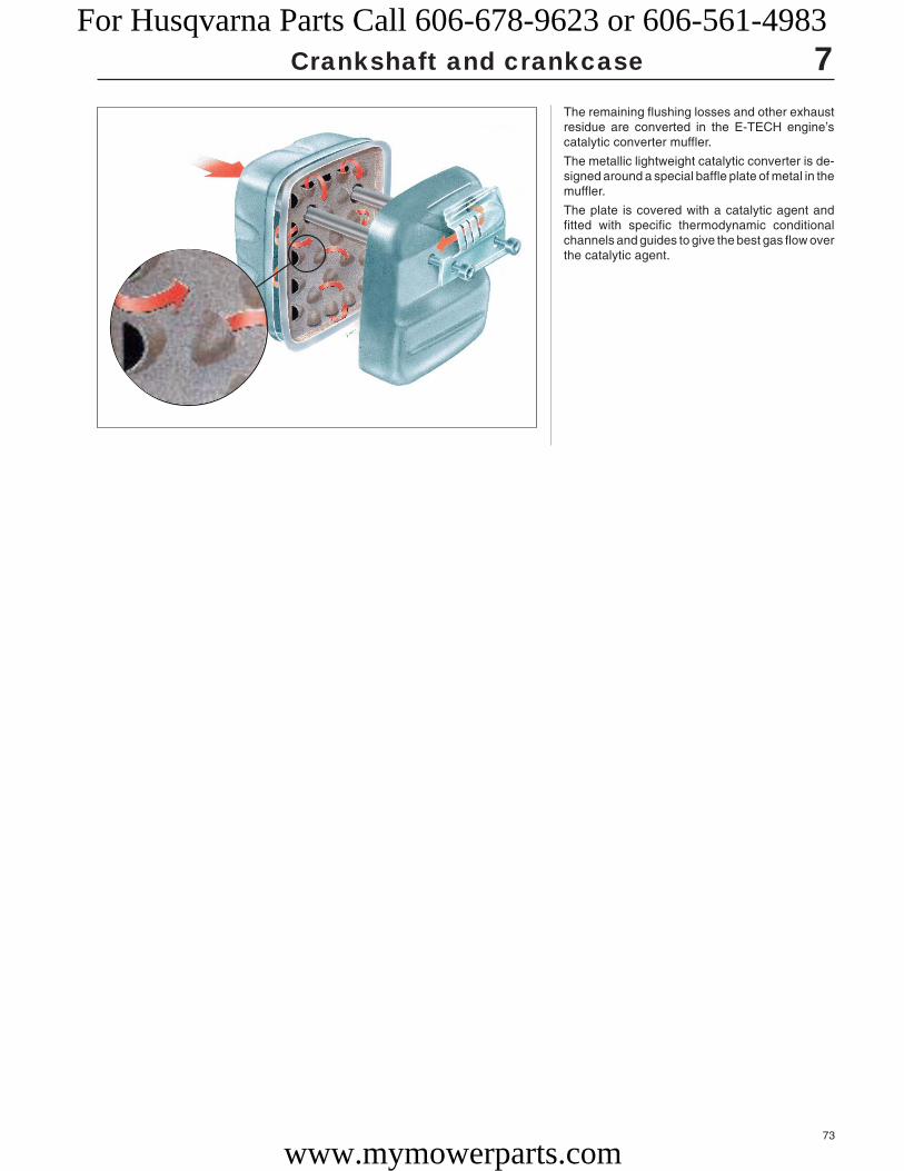
73
7Crankshaft and crankcase
The remaining flushing losses and other exhaustresidue are converted in the E-TECH engine’scatalytic converter muffler.
The metallic lightweight catalytic converter is de-signed around a special baffle plate of metal in themuffler.
The plate is covered with a catalytic agent andfitted with specific thermodynamic conditionalchannels and guides to give the best gas flow overthe catalytic agent.
For Husqvarna Parts Call 606-678-9623 or 606-561-4983
www.mymowerparts.com

74
For Husqvarna Parts Call 606-678-9623 or 606-561-4983
www.mymowerparts.com

75
8.Hydraulic unit
ContentsHydraulic pump, Dismantling, assembling, model 250PS __ 76
Test running, model 250PS ________________________ 78
For Husqvarna Parts Call 606-678-9623 or 606-561-4983
www.mymowerparts.com

76
8 Hydraulic unit
NOTE!The hydraulic pressure is high, and demands immensecare if leakage around connections has occurred. Re-place the gaskets and tighten the connections immedi-ately once a leakage has been discovered.
Cleanliness is extremely important with all work on thehydraulic system.
Hydraulics is an ideal solution to get a long andflexible power transmission between the engineand the cutting equipment.This has been utilised on model 235P, which isused for, e.g. tree pruning and on the pruning sawmodel 250PS. The power from the combustionengine is transferred to the hydraulic pump via acentrifugal clutch and from the pump to the cut-ting equipment via a flexible hydraulic hose.
Hydraulic pumpDismantling, assemblingModel 250PSDismantle the hydraulic oil tank from theengine unit and then the clutch drum.
Remove the cover on the tank and drainoff the hydraulic oil.
Hydraulic pumpDismantling, assemblingModel 250PSDismantle the hydraulic oil tank from theengine unit and then the clutch drum asdescribed in the chapter “Centrifugalclutch”.
Remove the 4 screws and lift off the coveron the tank.
Drain off all the hydraulic oil.
Unscrew the upper quick coupling andpress the hydraulic oil hose in the tank.
Unscrew the upper quick coupling andpress the hydraulic oil hose in the tank.
Dismantle the diffuser. Remove the lower quick coupling and liftout the diffuser from the tank.
For Husqvarna Parts Call 606-678-9623 or 606-561-4983
www.mymowerparts.com

77
8
AB
C
D
BGF
E
Hydraulic unit
Remove the axle from the pump housing.
Replace damaged parts and assemble inthe reverse order as set out for disman-tling.
Unscrew the hose from the hydraulic pumpand remove the 6 screws holding thecover (A).
Remove the cover and both impellers (B).
Remove the engine adapter. Remove all 8 screws holding the engineadapter on the hydraulic pump.
Start with the 4 inner screws.
Note how the pins on the adapter areplaced (half past 1 resp. half past 7).
Lift up the hydraulic pump together withthe cover disc from the tank.
Lift up the hydraulic pump together withthe cover disc from the tank.
Check that the rubber collar is undam-aged and keeps tight. Otherwise fit a newcollar.
Remove the key (E) from the pump axle(F).
Heat the pump housing (G) using a hot airgun to approx. 120°C. Now press out theaxle with the bearing from the pump hous-ing.
Use a suitable punch and hammer toknock the sealing ring out of the pumphousing.
Replace damaged parts and assemble inthe reverse order as set out for disman-tling.
NOTE!Note on which axle and in whatpump chamber in the cover thatresp. impellers are fitted so thatthese are given the same place-ment in subsequent assembly.
Remove the gear (C) and bearingsleeve (D).
For Husqvarna Parts Call 606-678-9623 or 606-561-4983
www.mymowerparts.com

78
8
502 42 45-01
MIN.
MAX.
Hydraulic unit
Check that the pump chambers are freefrom damage.
If this is not the case, replace bothimpellers and cover.
Assemble all remaining parts in the re-verse order as set out for dismantling.
Check that the pump chambers in thecover are not scratched. If this is not thecase, the cover and both impellers mustbe replaced.
The impellers must not show signs ofcracking or other damage. Replace bothimpellers at the same time if necessary.
Assemble all remaining parts in the re-verse order as set out for dismantling.
Make sure all hose connections are tight.
Fill with hydraulic oil to the correct level. Fill with hydraulic oil to the correct level.
Use oil of the quality ISO VG32 at airtemperatures under +20°C and ISO VG45at air temperatures above +20°C.
NOTE!The oil’s flash point should ex-ceed +160°C. The oil must not beelectrically conductive.
Check the oil level when the ma-chine has been run for 2-3 min andfill with more oil so that the levellies between min. and max. on theoil dipstick if necessary.
Test runningFit the test running hose no. 502 42 45-01on the upper and lower quick couplings.
Make sure the couplings make correctly.
Start the engine and test the pruning saw.
WARNING!Never start the pruningsaw without the hydrau-lic oil tank and hosesfitted. If the tank is notfitted the couplings canbecome loose and causepersonal injury.
!
For Husqvarna Parts Call 606-678-9623 or 606-561-4983
www.mymowerparts.com

79
9.Attachments
ContentsHedge trimmer, model 18H ________________________ 80
Blower, model 225HBV ____________________________ 82
Pruning saw, model 250PS ________________________ 83
Chain sprocket and bar __________________________ 85
Hydraulic motor ________________________________ 86
For Husqvarna Parts Call 606-678-9623 or 606-561-4983
www.mymowerparts.com

80
9
A
Attachments
Hedge trimmerModel 18HRemove the cover over the gearbox.
Hedge trimmerModel 18HRemove the 4 screws and lift off the coverover the gearbox.
Remove the cutting equipment. Unscrew the 2 screws and lift off thecutting equipment.
Lift off the gear. Lift off the gear.
Dismantle the steel loop and springs. Remove the 3 screws and lift off the steelloop together with the springs.
NOTE!Do not lose the small bearingsleeve (A).
For Husqvarna Parts Call 606-678-9623 or 606-561-4983
www.mymowerparts.com

81
9
502 50 57-01 502 52 16-01
504 90 90-01
A A
A
B
B
Attachments
Pull the bearing off of the clutch axle. Pull off both bearings at the same timefrom the clutch axle by using a smallpuller, e.g. no. 504 90 90-01.
Press out the gear with the bearing fromthe gearbox.
Press out the gear with the bearing fromthe gearbox.
Use a suitable punch and hammer.
Dismantle the clutch drum. Loosen (anti-clockwise) the axle (A) using the allen key502 50 57-01 (3/16") and possibly tool no.502 52 16-01.
Remove the screws (B).
Dismantle the clutch drum and the screws(B).
Unscrew the 4 screws and lift off thegearbox.
Dismantle the clutch housing.
NOTE!The screws (A) do not need to beremoved.
For Husqvarna Parts Call 606-678-9623 or 606-561-4983
www.mymowerparts.com
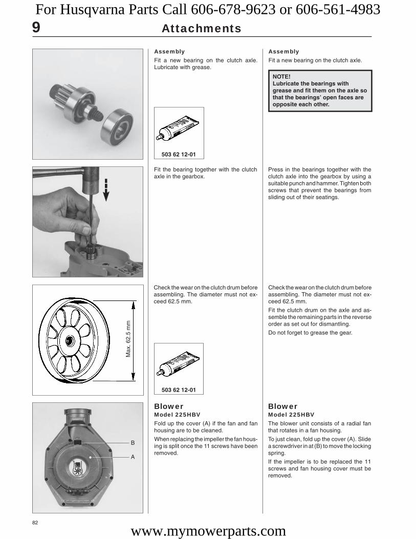
82
503 62 12-01
9
503 62 12-01
• A
B
Max
. 62.
5 m
m
Attachments
AssemblyFit a new bearing on the clutch axle.Lubricate with grease.
AssemblyFit a new bearing on the clutch axle.
Fit the bearing together with the clutchaxle in the gearbox.
Press in the bearings together with theclutch axle into the gearbox by using asuitable punch and hammer. Tighten bothscrews that prevent the bearings fromsliding out of their seatings.
Check the wear on the clutch drum beforeassembling. The diameter must not ex-ceed 62.5 mm.
Check the wear on the clutch drum beforeassembling. The diameter must not ex-ceed 62.5 mm.
Fit the clutch drum on the axle and as-semble the remaining parts in the reverseorder as set out for dismantling.
Do not forget to grease the gear.
BlowerModel 225HBVFold up the cover (A) if the fan and fanhousing are to be cleaned.
When replacing the impeller the fan hous-ing is split once the 11 screws have beenremoved.
BlowerModel 225HBVThe blower unit consists of a radial fanthat rotates in a fan housing.
To just clean, fold up the cover (A). Slidea screwdriver in at (B) to move the lockingspring.
If the impeller is to be replaced the 11screws and fan housing cover must beremoved.
NOTE!Lubricate the bearings withgrease and fit them on the axle sothat the bearings’ open faces areopposite each other.
For Husqvarna Parts Call 606-678-9623 or 606-561-4983
www.mymowerparts.com

83
9
504 91 06-05
502 52 23-01502 52 13-01
A
B B
C
Attachments
Dismantle the drive sprocket from thehydraulic motor.
Dismantle the drive sprocket from thehydraulic motor.
Hold the sprocket by using a pipe wrenchand turn the hydraulic motor’s axle clock-wise using the allen key no. 502 52 13-01.
Tip!The drive sprocket can be extremely tightand thereby difficult to hold with a pipewrench. If so, use holding tool no502 52 23-01.
Lift off the chain adjuster, chain and bar.Dismantle the chain adjuster, chain andbar.
Pruning sawModel 250PSDismantling
Remove the guard over the drive sprocket.
Loosen the chain adjuster screw (A) andremove the screws (B).
Replace the impeller if one or more of thefan blades are damaged.
Replace the spark plug with piston stopno. 504 91 06-05.
Remove the nut (anticlockwise) and liftoff the impact blades that disintegrate thegarden waste when the vacuum device isfitted. Remove the impeller.
Assemble in the reverse order as set outfor dismantling.
Replace the impeller if it is damaged.Otherwise the risk of damage due to vi-bration is great.
NOTE!The sheet rail at the periphery ofthe air shell should be positionedso that the bevelled corners faceoutwards.
Pruning sawModel 250PSDismantling
The cutting equipment consists of a chain,bar and hydraulic motor.
Remove the 2 screws holding the guardover the drive sprocket and loosen thechain adjuster screw (A).
Remove the screws (B).
NOTE!Do not lose the small O-ring (C)that lies behind the bar.Exercise care so that the gasketthat lies inside the chain adjusteris not damaged.
For Husqvarna Parts Call 606-678-9623 or 606-561-4983
www.mymowerparts.com

84
9
504 90 00-02
A
B
A
B
Attachments
Dismantle the hydraulic motor and barmounting.
Remove the 4 screws (A) holding thehydraulic motor and the 4 screws (B)holding the bar mounting against the balljoint bracket.
Loosen the hoses to the hydraulic motorand pull off the rubber sleeve holding thehoses together.
Loosen the hoses from the hydraulicmotor.
Pressure hose = hose coupling (A).
Return hose = hose clip (B).
Pull off the rubber sleeve holding thehoses together.
Dismantle the ball joint for replacement ifnecessary by removing the screw clip orthe fluted ring nut (newer models).
Pull apart the handle tube so that onehose at a time can be pulled through thefirst tube. Start with the return hose.
Take off the handle lock if necessary.
Now pull the hoses through the remaininghandle tubes.
For Husqvarna Parts Call 606-678-9623 or 606-561-4983
www.mymowerparts.com

85
9
502 42 15-01
502 42 16-01502 42 17-01
502 42 15-01
502 40 72-16502 40 73-02
Attachments
Replace the hose guide cover if it isdamaged.
Separate the halves using a screwdriver,loosen the hose clip and pull off the cover.
The hose guide cover on the lowest handletube can easily be replaced if damaged.
Insert a screwdriver in the cut-out in thejoint between both cover halves and twistapart.
Loosen the hose clip and pull off thecover.
Chain sprocket and barCheck that the chain sprocket rotatescentrically. If this is not the case thesprocket should be replaced with a newone.
Chain sprocket and barCheck that the chain sprocket rotatescentrically, i.e. the chain’s tension is thesame during its entire rotation.
If this is not the case the chain sprocketshould be replaced with a new one.
Assembly
Assemble the hoses in the reverse orderas set out for dismantling.
Slide both hoses through the handle tubesimultaneously.
Assembly is simplified if the hoses arepowdered and the pressure hose is placeda little before the return hose.
If the hydraulic hose has ruptured or is likelyto rupture close to a hose coupling it can besaved if cut square where ruptured andfitted with a special repair hose coupling.
Screw the outer, left-hand threaded sleeveof the house coupling on the hydraulichose as far as possible. Possibly lubricatewith oil or grease.
Now screw on the inner, right-handthreaded part of the hose coupling in theouter part.
NOTE!The black outer casing must notbe creased.
NOTE!When the ball-joint is fitted thelocking pin on the screw clampshould fit in the hole on the ball-joint.
For Husqvarna Parts Call 606-678-9623 or 606-561-4983
www.mymowerparts.com

86
9
A
Attachments
Check that the chain groove in the barand gear are in line. If this is not the casethe wear on the sprocket, chain and barwill be abnormally large and the servicelife short.
Replace the bar mounting and/or the chainsprocket to rectify the fault.
Check that the bar’s guides are on thesame level. If this is not the case the sawcut will be askew and wear on the chainuneven. If so, replace the bar and chain.
Hydraulic motorDismantling
Observe the greatest degree of cleanli-ness when dismantling and assemblingthe hydraulic motor. The smallest impuri-ties can cause downtime.
Hydraulic motorDismantling
Observe the greatest degree of cleanli-ness when dismantling and assemblingthe hydraulic motor. The smallest impuri-ties can cause downtime.
Blow out the oil channel (A) in the bar withcompressed air to ensure the nose wheeland chain receive sufficient lubrication.
NOTE!To obtain the maximum motorpower it is important that thecover and gear are in the sameposition after servicing as before.
1. Make a mark on the motor housingand cover.
1. Make a mark across the joint betweenthe motor housing and cover so thatthe parts have the same relative posi-tions after servicing.
NOTE!To obtain the maximum motorpower it is important that thecover and gear are in the sameposition after servicing as before.
For Husqvarna Parts Call 606-678-9623 or 606-561-4983
www.mymowerparts.com
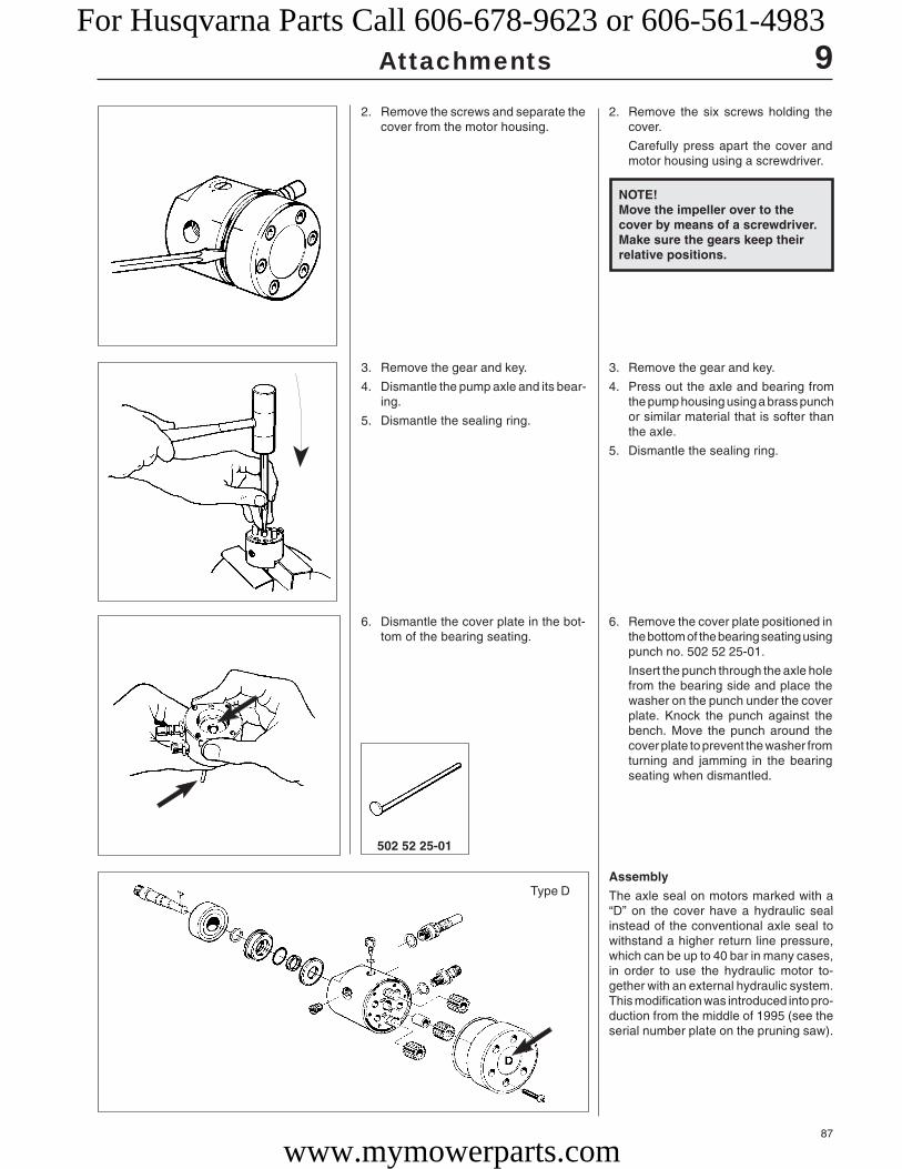
87
9
502 52 25-01
Type D
Attachments
2. Remove the screws and separate thecover from the motor housing.
2. Remove the six screws holding thecover.
Carefully press apart the cover andmotor housing using a screwdriver.
3. Remove the gear and key.
4. Dismantle the pump axle and its bear-ing.
5. Dismantle the sealing ring.
3. Remove the gear and key.
4. Press out the axle and bearing fromthe pump housing using a brass punchor similar material that is softer thanthe axle.
5. Dismantle the sealing ring.
Assembly
The axle seal on motors marked with a“D” on the cover have a hydraulic sealinstead of the conventional axle seal towithstand a higher return line pressure,which can be up to 40 bar in many cases,in order to use the hydraulic motor to-gether with an external hydraulic system.This modification was introduced into pro-duction from the middle of 1995 (see theserial number plate on the pruning saw).
6. Dismantle the cover plate in the bot-tom of the bearing seating.
6. Remove the cover plate positioned inthe bottom of the bearing seating usingpunch no. 502 52 25-01.
Insert the punch through the axle holefrom the bearing side and place thewasher on the punch under the coverplate. Knock the punch against thebench. Move the punch around thecover plate to prevent the washer fromturning and jamming in the bearingseating when dismantled.
NOTE!Move the impeller over to thecover by means of a screwdriver.Make sure the gears keep theirrelative positions.
For Husqvarna Parts Call 606-678-9623 or 606-561-4983
www.mymowerparts.com

88
9
502 52 24-01
A BC
Attachments
1. Place the seal retainer (C) on theaxle with the flange facing the bear-ing.
1. Place the seal retainer on the axlewith the flange facing the bearing.
2. Slide the sealing ring (A) into position.
3. Press down the O-ring (B) correctly inthe gap between the sealing ring andthe seal retainer.
2. Lubricate the axle with a few drops ofoil and slide the sealing ring (A) care-fully over the axle’s sealing surface.
3. Press down the O-ring (B) betweenthe sealing ring and the seal retainer.Use your thumb nail!
5. Fit the axle with the bearing fitted inthe motor housing.
Check that the axle can rotate freely.
5. Press in the axle with the bearing fittedin the motor housing. Hold the housingin your hand and press in the bearingusing sleeve no. 502 52 24-01. Checkthat the axle can rotate freely.
4. Place the cover plate, with the cham-fer facing inwards, in position on themotor housing.
4. Place the cover plate in position in themotor housing. The chamfer shouldface inwards to facilitate assembly.
NOTE!Check that the O-ring sitscorrectly in the gap between thesealing ring and retainer.
NOTE!Motors manufactured before themiddle of 1995 (no “D” markingon the cover) have a metal discplaced on the outside of thesealing ring. This disc must notbe fitted when the abovementioned seal type is used.
For Husqvarna Parts Call 606-678-9623 or 606-561-4983
www.mymowerparts.com

89
9
502 42 50-01
Type E
Attachments
6. Check that the O-ring is undamagedand fit the key in the axle. Place thegear and pump impeller in position inthe cover and secure it in place on themotor housing.
6. Check that the O-ring, which sealsbetween the cover and the motor hous-ing, is undamaged.
Fit the key on the axle.
Place the gear and impeller in posi-tion in the cover so that they come inthe same position relative to eachother as before servicing.
Fit the cover on the motor housing.Rotate the axle so that the key entersthe gear.
Make sure the marking on the coveraligns with the mark on the motorhousing.
Tighten the screws crosswise and di-agonally.
In connection with the introduction of thehydraulic seal type “D” the relief valvemust be replaced with one that has ahigher opening pressure (40 bar).
This valve has order no. 503 83 17-01.
Use tool no. 502 42 50-01 to replace thevalve.
In connection with the introduction of thehydraulic seal type “D” the relief valvemust be replaced with one that has ahigher opening pressure.
This valve has order no. 503 83 17-01.
Use tool no. 502 42 50-01 to replace thevalve.
The hydraulic motors with the designa-tion “E” punched on the cover have aslightly different seal mounting comparedwith type “D”.
On these motors the hydraulic seal is thesame as on the “D” type, but is fitteddirectly in the motor housing without theseal holder (C).
The new mounting, type “E”, has beenintroduced into production from serialnumber 709 50 33 on the handle.
For Husqvarna Parts Call 606-678-9623 or 606-561-4983
www.mymowerparts.com

90
For Husqvarna Parts Call 606-678-9623 or 606-561-4983
www.mymowerparts.com

91
10.Tools
ContentsAngle gear/gearbox _______________________ 92
Centrifugal clutch _________________________ 93
Bearing/crankcase/vib. damper/crankshaft _____ 94
Sealing ring ______________________________ 95
Fuel system/ignition system _________________ 96
Leakage testing __________________________ 97
Hydraulic unit ____________________________ 98
Attachments _____________________________ 99
Cylinder and piston/workshop equipment _____ 100
For Husqvarna Parts Call 606-678-9623 or 606-561-4983
www.mymowerparts.com

92
502 51 11-01
265
252
250
240/245
225/232/235
240RBD
122
32
Mondo Mega
Mondo
Mondo Max
250PS
235P
225 H60/H75
18H
322
325
140B, 141B
502 51 68-01 502 50 65-01 503 97 64-01 503 62 12-01 503 80 17-01
● ● ●
● ● ●
● ● ●
● ●
●
● ●
●
●
●
●
●
●
●
●
●
10
Angle gear, gearbox
Mo
del
List of tools
For Husqvarna Parts Call 606-678-9623 or 606-561-4983
www.mymowerparts.com
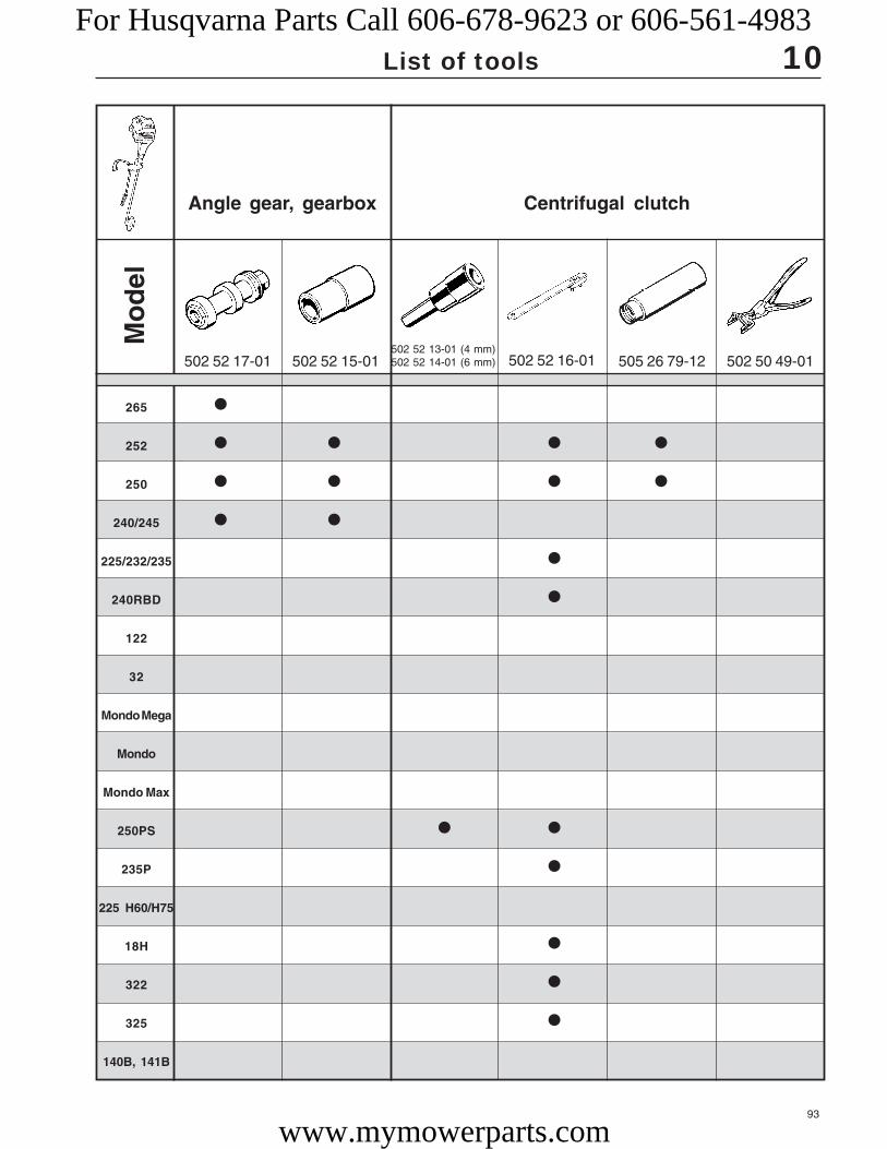
93
265
252
250
240/245
225/232/235
240RBD
122
32
Mondo Mega
Mondo
Mondo Max
250PS
235P
225 H60/H75
18H
322
325
140B, 141B
502 52 17-01 502 52 15-01 502 52 16-01 505 26 79-12 502 50 49-01
●
● ● ● ●
● ● ● ●
● ●
●
●
● ●
●
●
●
●
502 52 13-01 (4 mm)502 52 14-01 (6 mm)
10
Angle gear, gearbox
Mo
del
Centrifugal clutch
List of tools
For Husqvarna Parts Call 606-678-9623 or 606-561-4983
www.mymowerparts.com

94
265
252
250
240/245
225/232/235
240RBD
122
32
Mondo Mega
Mondo
Mondo Max
250PS
235P
225 H60/H75
18H
322
325
140B, 141B
18 mm
504 90 90-01 502 51 61-01 502 50 66-02 502 50 30-10 502 50 30-07
● ● ●
● ● ●
● ● ●
● ●
●
● ● ●
● ●
●
502 50 30-08
10M
od
el
Bearing Crankcase Vibrationdamper
Crankshaft
List of tools
For Husqvarna Parts Call 606-678-9623 or 606-561-4983
www.mymowerparts.com

95
505 38 17-09504 91 28-06502 50 30-09 504 91 40-01 502 50 53-01 504 91 28-00
● ● ● ● ●
● ● ● ● ●
● ● ● ● ●
● ●
●
●
●
●
●
● ● ● ●
●
●
265
252
250
240/245
225/232/235
240RBD
122
32
Mondo Mega
Mondo
Mondo Max
250PS
235P
225 H60/H75
18H
322
325
140B, 141B
10
Mo
del
Sealing ringCrankshaft
List of tools
For Husqvarna Parts Call 606-678-9623 or 606-561-4983
www.mymowerparts.com

96
265
252
250
240/245
225/232/235
240RBD
122
32
Mondo Mega
Mondo
Mondo Max
250PS
235P
225 H60/H75
18H
322
325
140B, 141B
502 50 83-01 501 60 02-02 531 00 48-63 502 51 94-01 502 71 13-01
CARB EPA
● ● ●
● ● ●
● ● ●
● ● ● ●
● ● ● ● ●
● ● ● ●
● ● ●
● ● ● ●
● ● ● ●
● ● ● ●
● ● ● ●
● ● ● ●
● ● ● ●
● ● ● ●
● ● ● ●
● ● ● ●
● ● ● ●
● ●
505 26 79-12
10
Fuel system Ignition system
Mo
del
List of tools
For Husqvarna Parts Call 606-678-9623 or 606-561-4983
www.mymowerparts.com
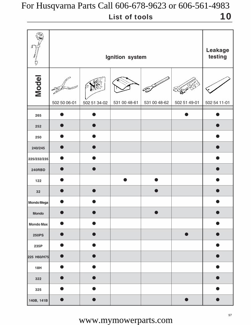
97
265
252
250
240/245
225/232/235
240RBD
122
32
Mondo Mega
Mondo
Mondo Max
250PS
235P
225 H60/H75
18H
322
325
140B, 141B
502 51 34-02 531 00 48-61 531 00 48-62 502 51 49-01 502 54 11-01502 50 06-01
● ● ● ●
● ● ●
● ● ●
● ● ●
● ● ●
● ● ●
● ● ● ●
● ● ● ●
● ● ●
● ● ● ●
● ● ●
● ● ● ●
● ● ●
● ● ●
● ● ●
● ● ●
● ● ●
● ● ● ●
10
Mo
del
Ignition systemLeakagetesting
List of toolsFor Husqvarna Parts Call 606-678-9623 or 606-561-4983
www.mymowerparts.com

98
265
252
250
240/245
225/232/235
240RBD
122
32
Mondo Mega
Mondo
Mondo Max
250PS
235P
225 H60/H75
18H
322
325
140B, 141B
502 50 37-01502 50 38-01 502 52 28-01 502 52 30-01
● ● ●
● ● ●
● ● ●
● ● ●
● ● ●
● ● ●
● ● ●
● ● ●
● ● ●
● ● ●
● ● ●
● ● ● ● ●
● ● ● ● ●
● ● ●
● ● ●
● ● ●
● ● ●
● ● ●
503 84 40-01
+ –
502 42 45-01
10M
od
el
Leakage testing
List of tools
Hydraulic unit
For Husqvarna Parts Call 606-678-9623 or 606-561-4983
www.mymowerparts.com

99
265
252
250
240/245
225/232/235
240RBD
122
32
Mondo Mega
Mondo
Mondo Max
250PS
235P
225 H60/H75
18H
322
325
140B, 141B
502 52 26-01 502 52 27-01
● ● ● ●
● ●
502 42 50-01 502 52 23-01502 52 24-01 502 52 25-01
10
Attachments
Mo
del
List of tools
For Husqvarna Parts Call 606-678-9623 or 606-561-4983
www.mymowerparts.com

100
265
252
250
240/245
225/232/235
240RBD
122
32
Mondo Mega
Mondo
Mondo Max
250PS
235P
225 H60/H75
18H
322
325
140B, 141B
503 26 70-01502 50 70-01 505 38 17-05531 00 48-65
● ● ●
● ● ●
● ● ●
● ● ● ●
● ● ● ●
● ● ● ●
● ● ● ●
● ● ●
● ● ● ●
● ● ● ●
● ● ● ●
● ● ●
● ● ● ●
● ● ● ●
● ● ● ●
● ● ● ●
● ● ● ●
● ● ●
504 91 06-05 502 54 15-01
10
Workshopequipment
Cylinder/piston
Mo
del
List of tools
For Husqvarna Parts Call 606-678-9623 or 606-561-4983
www.mymowerparts.com

101
265
252
250
240/245
225/232/235
240RBD
122
32
Mondo Mega
Mondo
Mondo Max
250PS
235P
225 H60/H75
18H
322
325
140B, 141B
504 90 00-02 504 90 00-03 504 90 00-01
4 mm 5 mm 6 mm
504 90 00-06
504 90 00-01–04+ 502 50 22-01
=3/16"
502 50 57-01
3 mm
504 90 00-04
●
● ●
● ●
● ●
●
●
●
●
● ●
●
● ●
●
●
●
● ●
● ●
● ●
10
Mo
del
Workshop equipment
List of tools
For Husqvarna Parts Call 606-678-9623 or 606-561-4983
www.mymowerparts.com

102
265
252
250
240/245
225/232/235
240RBD
122
32
Mondo Mega
Mondo
Mondo Max
250PS
235P
225 H60/H75
18H
322
325
140B, 141B
M 6
502 51 67-01 502 50 88-01502 50 22-01
8 mm
502 50 23-01
10 mm
502 71 27-01
25 x 150
502 71 31-01
30 x 200
●
● ●
10M
od
el
Workshop equipment
List of tools
For Husqvarna Parts Call 606-678-9623 or 606-561-4983
www.mymowerparts.com

103
265
252
250
240/245
225/232/235
240RBD
122
32
Mondo Mega
Mondo
Mondo Max
250PS
235P
225 H60/H75
18H
322
325
140B, 141B
505 69 85-70502 02 61-02 502 71 14-01 502 51 03-01
● ● ● ●
● ● ● ● ●
● ● ● ● ●
● ● ● ● ●
● ● ● ●
● ● ● ●
● ● ● ●
● ● ●
● ● ●
● ● ●
● ● ●
● ● ● ●
● ● ● ●
● ● ●
● ●
● ● ● ●
● ● ● ●
● ● ●
M 5
502 50 87-01
M 4
502 50 86-01
10
Mo
del
Workshop equipment
Degreasing agent
List of tools
For Husqvarna Parts Call 606-678-9623 or 606-561-4983
www.mymowerparts.com

104
265
252
250
240/245
225/232/235
240RBD
122
32
Mondo Mega
Mondo
Mondo Max
250PS
235P
225 H60/H75
18H
322
325
140B, 141B
● ●
● ●
● ●
●
●
●
●
●
●
●
●
●
●
●
●
●
●
●
Size S: 101 64 23-48M: 101 64 23-50L: 101 64 23-52
XL: 101 64 23-54XXL: 101 64 23-56502 51 54-01 502 21 58-01
10M
od
el
Workshop equipment
List of tools
For Husqvarna Parts Call 606-678-9623 or 606-561-4983
www.mymowerparts.com