Brownie’s NOT ADD OXYGEN TO THE COMPRESSOR: THERE IS A DANGER OF EXPLOSION. 8 INSTALLATION...
59
YP45DF Yacht Pro Automatic Compressor Operator’s Manual This manual is also available online 940 NW First Street, Fort Lauderdale, FL 33311 USA Ph 954-462-5570 Fx 954-462-6115 [email protected] www.BrowniesMarineGroup.com Brownie’s MARINE GROUP
Transcript of Brownie’s NOT ADD OXYGEN TO THE COMPRESSOR: THERE IS A DANGER OF EXPLOSION. 8 INSTALLATION...

YP45DF
Yacht Pro Automatic CompressorOperator’s Manual
This manual is also available online
940 NW First Street, Fort Lauderdale, FL 33311 USAPh 954-462-5570 Fx 954-462-6115
w w w . B r o w n i e s M a r i n e G r o u p . c o m
Brownie’sM A R I N E G R O U P

2

3
PREFACE
Thank You for purchasing a Brownie’s Yacht Pro Series Compressor System. This manualexplains the use and maintenance of your unit. All information here is based on the latest productdata available at the time of publication. Brownie’s Third Lung reserves the right to makeunannounced changes at any time without incurring any obligations whatsoever.
This Operator’s Manual is to be considered a part of the overall compressor package andshould remain with the compressor in the event of sale to another party.
In order to familiarize yourself with the compressor features, please read this manual thoroughlybefore using the equipment. Physical layout is pictured on page 28.
For service, please contact:BROWNIE’S THIRD LUNG
940 NW First StreetFort Lauderdale, FL 33311
(954) 462-5570 Phone(954) 462-6115 Fax
www.tankfill.com / [email protected]
IMPORTANT NOTICE:Read this manual before you operate your Yacht Pro Series Compressor, as it containspertinent information for the safe operation of the system. Failure to follow theinstructions in this manual may result in damage to the compressor and/or personalinjury or death.
WARNING: Installation and operation of the system without the guidelines setforth in this manual may result in damage to the system and/or personal injuryor death.
WARNING: Never tamper with or modify factory settings. This will void thewarranty and could result in personal injury or death.

4
Copyright ©2by Brownie’s Third LungAll rights reserved. No part of this manual may be reproduced in any form by any means without permission inwriting from the publisher.
Edition 5.0 02/2005
Table of Contents
Preface 3Table of Contents 4Quality Analysis 5Product Data 6Description of Unit 7Standard Features 8Installation 8Pre Start-Up Checks 9Tankfill Procedures 10Purification System 11Lubrication Specifications 11Maintenance Schedule 12Torque Valves and Sequencing 13Valves 14Drive Belt 16V-belt Tension Adjustment 16Cooling System 16Oil Level Check 17Oil Types 17Intake Filter 17Sightglass Element Change Demonstration 18Black Filter Cartridge Replacement Demonstration 20Gold Filter Cartridge Replacement Demonstration 22Tankfill Demonstration 24Oil Change Demonstration 27Troubleshooting 36Systems Operations Log 38Warranty Information 45
Physical Layout Features:Figure 1 Black Filter Cartridges 20Figure 2 Gold Filter Cartridges 22Figure 3 Front and Rear Compressor View 28Figure 4 Auto Drain System & Comp. Features 29Figure 5 Black Filter Tower Exploded View 35
Parts Drawings:Parts Drawing 1 Crankcase 30Parts Drawing 2 Pistons and Cylinders 32Parts Drawing 3 Intake/Intermediate Seperator 34

5
Date:
Serial # Model # Order#
Motor Wiring V PH HZ
Belt Size Tension
Connections Tight Nuts & Bolts Tight
No Leaks
Control Wiring Correct Final Pressure Setting
Drain System Operation Interval
Oil Level Tank Fill Time(80 ft³ 500-3000 PSI)
Hour Meter Reading Test Run Time
STANDARD EQUIPMENT PROVIDED
Filter Sightglass Elements
Manual Lubricant
OPTIONAL EQUIPMENT ORDERED
4TKMAN HIP-RFPK
FC374-04RL (Additional for 4TKMAN Main) FT
Transformer Oil Removed
Technician Installer
123456789012345678901234567890121234567890123456789012345678901212345678901234567890123456789012123456789012345678901234567890121234123456789012345678901234567890121234567890123456789012345678901212345678901234567890123456789012123456789012345678901234567890121234123456789012345678901234567890121234567890123456789012345678901212345678901234567890123456789012123456789012345678901234567890121234123456789012345678901234567890121234567890123456789012345678901212345678901234567890123456789012123456789012345678901234567890121234123456789012345678901234567890121234567890123456789012345678901212345678901234567890123456789012123456789012345678901234567890121234123456789012345678901234567890121234567890123456789012345678901212345678901234567890123456789012123456789012345678901234567890121234123456789012345678901234567890121234567890123456789012345678901212345678901234567890123456789012123456789012345678901234567890121234123456789012345678901234567890121234567890123456789012345678901212345678901234567890123456789012123456789012345678901234567890121234123456789012345678901234567890121234567890123456789012345678901212345678901234567890123456789012123456789012345678901234567890121234
COMPRESSOR QUALITY ANALYSIS RECORD

6
Product Data123456789012345678901234567890121234567890123456789012345678901212345678901234567890123456789012123456789012345678901234567890121234123456789012345678901234567890121234567890123456789012345678901212345678901234567890123456789012123456789012345678901234567890121234123456789012345678901234567890121234567890123456789012345678901212345678901234567890123456789012123456789012345678901234567890121234123456789012345678901234567890121234567890123456789012345678901212345678901234567890123456789012123456789012345678901234567890121234123456789012345678901234567890121234567890123456789012345678901212345678901234567890123456789012123456789012345678901234567890121234123456789012345678901234567890121234567890123456789012345678901212345678901234567890123456789012123456789012345678901234567890121234
Category Specifications Free Air Displacement (a)(b): 4.1 scfm* Operating Pressure (Std): 3200 PSI ** Pressure setting, final 3400 PSI pressure safety valve (STD) Dimensions: 36”L x 17”W x 18”H (91 x 44 x 46 cm) Weight: Approx 185 lbs (84kg) Use: Compression of atmospheric air. Intake Pressure: Atmospheric Pressure Compressor RPM: 1800 Drive Belt Type: 3VX355 Number of Stages 3 Number of Cylinders 3 Cylinder Bore 1st Stage 70 mm Cylinder Bore 2nd Stage 28 mm Cylinder Bore 3rd Stage 12 mm Piston Stroke 24 mm Intermediate Pressure 1st Stage 94 psi / 6.5 barIntermediate Pressure 2nd Stage 843 psi / 65 barCompressor Block Oil Cap. 1.4qt. / 1.3L Recommended Oil Types: CF-2000 Synthetic Compressor Lubricant Max. ambient temperature +43º to +100º F
+5º to +38º C Max. permissible inclination 10º of compressor (b):
* Unit has a max pressure rating of 5000 psi (3800 psi recommended)** May be set higher or lower based on Pressure Switch settings*** Electric motors also available; 3 phase, 50 or 60 HZ; and Single Phase 50 HZ(a) free air delivered at tank filling from 0 to 3000 psi(b) Value only valid if oil in level unit position is at highest mark on dipstick.

7
DESCRIPTION OF THE UNIT:Your Yacht Pro Series is a fully automatic compressor, equipped with Automatic Condensate Drain (ACD). The YPseries has been designed specifically with the traveling yacht owner in mind. The compressor system is designed for“HANDS FREE” operation.
STANDARD FEATURESThe complete Yacht Pro Series package includes:
• Dual Programmable Stainless Condensate Drain System Switch• Digital Frequency Drive Control System• One High Pressure Compressor with a 5HP (YP45DF) Motor• Stainless Programmable Digital Pressure Switch with LED Display• One Condensate Collection Jug• One Purification Cartridge (X22679 for Gold Tower)• One Purification Cartridge (X53240 for Black Tower)• One Operator’s Manual• One Sightglass Element (moisture and CO monitor)• Tool Kit• One liter, Synthetic Compressor Oil
The following are included with the YP45DF• One Four-way Manifold with 10 foot connection hose including stainless steel quick disconnect end• One ½ inch padded Custom Cordura Manifold Bag
NOTICE:Please read this Owner’s Manual before you operate your Yacht Pro Series Compressor
Optional Equipment:• One Starboard Mounting and Spill Containment Tray• Stainless Steel Quick Disconnect Set• Custom Hose Lengths• Remote Fill Plumbing Kit• Cordura Nylon Cover• Remote On/Off Switch (with installation)
WARNINGS:• Do not operate the compressor if the compressor is damaged.• Do not operate the compressor near flammable substances or objects• Make sure the air entering the compressor is clean atmospheric air.• Do not operate unit in Ambient Temperatures exceeding 100ºF (38ºC)
USE OF COMPRESSOR:The Yacht Pro Series is intended for the compression of air and other gas mixtures.
WARNING:DO NOT ADD OXYGEN TO THE COMPRESSOR: THERE IS A DANGER OF EXPLOSION.

8
INSTALLATIONWARNING:Improper installation may result in damage to the unit, personal injury or death.
All persons operating the Yacht Pro Series system must read this manual completely and fully understand theprocedures for system operation and the responsibilities of the operator to insure the safety of divers supplied withair from the system. We recommend professional installation by our experienced installation technicians. The YachtPro Series must not be operated in an enclosure that does not meet the installation/operation guidelines for the unit.Contact our Technical Department for advice.
The Yacht Pro series tank fill compressor must be installed in accordance with the following recommendations:
1. Ambient temperature during operation must not exceed 100 deg F (38 deg C) maximum. The unit will produce heatwhen operating, therefore adequate ventilation must be provided to stay well within the maximum limit listed above.We recommend operating unit well below the maximum limit. Forced Ventilation must be used where poor aircirculation is present. Contact our Technical Department with questions regarding proper ventilation.
2. Proper clearances must be allowed for the following:a. 6" minimum from the fan cover to any bulkhead. This provides adequate air supply for the cooling fan.b. 8" minimum above the filter tower. This allows easy filter removal/replacement and easy access to remove
the oil dipstick for checking/changing oil.c. Allow working access to the electrical box for service/repair.d. The Oil drain tube must have clearance for oil changes.e. The condensate drain reservoir must be accessible for removal.f. Hour meter, on/off switch, and visual monitor must be accessible for safe operation.g. Belt Guard must be accessible for service of drive belt.
3. The unit must be installed on a flat, level surface. No more than 10 deg inclination must occur during operation.
4. The Yacht Pro Series units are provided as a complete assembly ready for installation. NOTE: Someinstallations may require remote mounting of package components. This must be approved by our TechnicalDepartment.
NOTE: Any alterations of the original system without approval by our technical department will void themanufacturer’s warranties.
5. Clean, fresh air must be provided to the air intake of the compressor as close to the operating ambienttemperature of the unit as possible. Remote air intake plumbing may be required. A non-collapsible plastic hose with3/4" ID is the simplest method. The 3/4" ID may be run for a length of 10'. Longer runs may be used by following thisguideline: For every 10' of run the preceding 10' diameter must be doubled. All 90 deg fittings should be consideredas 1 foot of length.
NOTE: The intake must be protected from water entry, as this will cause severe damage to the unit.
6. The unit must be protected from any type of water exposure. Such exposure will seriously effect the longevity ofthe unit and may result in personal injury or death.
7. Electrical Requirements:Yacht Pro series compressors come standard with 220 VAC 60HZ single phase electric motors. They are equipped with120 VAC 60HZ controls and components. All units require correct electrical supply components be provided inaccordance with local, state and federal codes for land installation and marine codes for on-board installation. Anelectrician should be consulted for supply power recommendations. Standard units require that a neutral wire be providedwith the standard power supply, for correct operation. An optional remote transformer can be used to provide controlvoltage if neutral is not available. Some voltage and cycle combinations will require an optional transformer for correctoperation.Yacht Pro Series are available for other electrical requirements. Please contact our Technical Department forspecifications.

9
WARNING: Divers lives depend upon proper operation of the system.Brownie’s Third Lung highly recommends that all system operators take aSystem Training Course.
PRE START-UP CHECKS
Consult the system log to see if the following maintenance needs to be done:
• Purification Cartridge inspection/replacement (see pages 11, 20, 22)• Sightglass Element replacement (see page 18) (6 month installed life)• Oil Check/Change (see pages 17, 27)
1. Check oil levelThe oil level must be between the upper and lower marks on the dipstick (see picture page 17). If the oil is low, addoil through the dipstick tube. Use only Brownie’s recommended oil (see page 11 for recommended oils). Do not mixoils or use non-recommended oils which may adversely affect the life of the unit or even destroy the unit.
2. Check Purification CartridgesInspect both cartridges by following the procedure on page 11. Replace either cartridge if present cartridge has beenused up or the cartridge has been in place for 6 months. (This is the maximum installed life of the purificationcartridges. If the cartridges are close to expiration, Brownie’s recommends replacing the cartridge with a new one.)Replacement Cartridge for the Black Tower is X53240. Replacement cartridge for the Gold Tower is X22679.
WARNING: Failure to monitor or replace the purification cartridge WILL contaminate all airlines, fill assemblies, divers air tanks, regulators, and may cause severe injury or even diverdeath. The system operator is responsible for the lives and safety of the divers using airproduced by the system.
3. Check Visual Carbon Monoxide / Moisture IndicatorThe visual indicator has two elements. An outer blue ring for indicating the presence of moisture, and a central tan toorange disc, indicating the presence of carbon monoxide. Any change in color, (the central disc (CO) turns darkbrown or has black spots, and/or the outer ring (moisture) turns pink or beige, indicates that the air leaving thepurification system is contaminated and not breathable. The visual monitor is the last monitor of the air leaving thepurification system, and must be checked during operation for any changes.
WARNING: Any color change in the elements of the visual indicator means thatcontaminated air has passed downstream. All air lines, fill assemblies, and equipment mustbe cleaned or replaced. An Air Test must be done to insure thoroughness of all cleaning.Breathing contaminated air may result in personal injury or death.
4. Check Air IntakeRemove and inspect the Air Intake Filter. If the system is equipped with a remote air intake, be sure it is properlylocated, and clear of any water or obstructions.
5. Add all pre-startup maintenance/inspection notations to the system log with date, hours, and operator name.
6. Inspect ALL tanks to be filled:• Make sure the tanks are in good condition with no deep scratches, gouges, or pitting.• The tanks must be within current hydrostatic test and Visual Inspection dates.• Do not fill empty tanks without first visually inspecting them for water intrusion.• Make sure that the valves are in good condition and not in need of service. Do not fill tanks with damaged valves.• Do not fill tanks that have been exposed to extreme heat, i.e.: tanks that have been in or near fires.• Do not fill tanks designated for air with other gas mixtures, ie: Nitrox, Trimix, etc.

10
TANKFILL PROCEDURES(See Demonstration p 24-26)
WARNING: Tanks must be secured (protected from falling or being knocked over) during filling.
1. Hook up fill manifold to compressor air outlet or remote fill panel.
2. Slightly open tank valve just long enough to blow any moisture or particles clear of connection surfaces.
3. Standard Yoke - Hook fill yokes to the tank valves and tighten yoke hand wheel “finger tight”. Close bleed screwsand open tank valves. Open the fill yoke valves. The tanks will now equalize.
Din Yoke - Screw the male din yokes into the valves until the “o-ring” is snugly in place against the base of thefemale din valves. Close bleed screws and open tank valves. Open the fill yoke valves. The tanks will now equalize.
4. Start the CompressorNote the indicator light is now on. If the compressor is equipped with a dual pressure switch, be sure the controlswitch is in the correct pressure position (high or low) for the tanks being filled. The compressor will now operateautomatically, draining the condensate and shutting off when the tanks are full. The operator need only check theoperation from time to time during the filling process to verify the following:
• Condensate is accumulating in the reservoir.• No color change has occurred in the visual indicator.• Pressure is building on the fill gauge.
Fill times are based on filling a single standard 80 cu ft aluminum cylinder from 500 psi to 3000 psi and areapproximately as follows: YP45DF - 16 minutes per tank. Cylinder volume, starting tank pressure, and tank pressureratings will vary the fill times.
WARNING: Brownie’s recommends a two hour (approximately 4 tanks) duty cycle, with a onehour period between cycles.
Note that the indicator light is still on after the compressor automatically stops. This indicates that the compressoris in an AUTOMATIC START MODE and will restart if the stop pressure drops approximately 500 psi.
If you intend to fill more tanks you may leave the on/off switch in the “on” position while changing the tanks out.Simply opening the tank and fill yoke valves will restart the compressor.
5. Remove full tanks by first closing the fill yokes and tank valves. Depressurize the yokes by opening the bleedscrews. Remove the fill yokes from the tanks.
6. When you are done filling for the day, turn the on/off switch to the off position. Empty the condensate reservoir.
7. Bleed the pressure from the fill manifold by opening one of the fill yoke valves slowly until all pressure is ventedand the gauge reads zero.
8. Remove the manifold from the hose using the quick disconnect and store the manifold in its bag.
WARNING: Do not try to remove the quick disconnect while the system is pressurized. Doing somay result in property damage or personal injury.
9. Allow the compressor to cool prior to installing the optional Cordura fabric cover.
10. Update the system log, noting running hours of compressor and any maintenance performed.

11
PURIFICATION SYSTEM
Explanation:The YP45DF compress air in three stages. Air leaving the outlet (discharge) of each stage is at an elevated tempera-ture. The air passes through cooling tubes and the temperature is reduced prior to entering the inlet of the nextstage. As this air cools, moisture is released and accumulates in the condensate traps (separators). This process ofmoisture removal is based on dew point. Dew point is the total moisture saturation point of air at a specific tempera-ture. The higher the temperature, the greater the amount of suspended moisture. When air leaves the last or finalseparator and enters the purification cartridge it is at approximately 15 deg F above the ambient temperature. Thistemperature is referred to as inlet temperature. Higher inlet temperatures reduce the life of the purification cartridge.
As an example, an ambient temperature of 90 deg F will yield an inlet temperature of 105 deg F. The life of thepurification cartridge at this temperature will be significantly less than a cartridge processing air at an 80 deg Fambient temperature, which yields a 95 deg F inlet temperature.
The Yacht Pro purification system will process 15,000 cu ft of CGA Grade “E” Air at an inlet temperature of 80 deg F.At this inlet temperature the purification system cartridges should last approximately 60 hours in the YP45DF.
The Yacht Pro Purification system uses three chemicals to process the air. The first chemical is molecular sieve13x, and is the desiccant or moisture/oil remover. The second chemical is a catalyst called hopacolite, that convertscarbon monoxide to carbon dioxide. The third chemical is activated carbon which removes taste and odor. TheX53240 cartridge uses a Lifeband™ to indicate usage and replacement (see page 21). The cartridge Lifeband ™should be inspected prior to each use to determine whether the cartridge needs to be replaced. The hours thecartridge is used and replaced needs to be recorded in the system log.
The Yacht Pro purification cartridges have a shelf life of two years in the original sealed package and a maximuminstalled life of six months.
Spare cartridges should be kept in a cool, dry location. The boxes must not be crushed and the packaging must notbe punctured.
WARNING: Do not use cartridges that have expired, have punctured packaging or that aredamaged in any way!
123456789012345678901234567890121234567890123456789012345678901212345678901234567890123456789012123456789012345678901234567890121234123456789012345678901234567890121234567890123456789012345678901212345678901234567890123456789012123456789012345678901234567890121234123456789012345678901234567890121234567890123456789012345678901212345678901234567890123456789012123456789012345678901234567890121234123456789012345678901234567890121234567890123456789012345678901212345678901234567890123456789012123456789012345678901234567890121234123456789012345678901234567890121234567890123456789012345678901212345678901234567890123456789012123456789012345678901234567890121234123456789012345678901234567890121234567890123456789012345678901212345678901234567890123456789012123456789012345678901234567890121234123456789012345678901234567890121234567890123456789012345678901212345678901234567890123456789012123456789012345678901234567890121234123456789012345678901234567890121234567890123456789012345678901212345678901234567890123456789012123456789012345678901234567890121234
Lubrication Specifications
Use Lubricant
O-rings, rubber and plastic parts, White Petroleum DAB9 # N19091 or WEICON WP 300filter housing threads White part # N19752
Sealing Rings Universal grease
Paper Gaskets Apply silicone compound on both sides (WACKERsilicone compound part # N 18247) before assembly
Bolts, nuts, studs, valve parts, CU gaskets and pipe Compounds with Copper or MoS² additives (WEICONconnectors (threads, cap nuts, compression rings) ANTI-SEIZE AS 040 P part # N 19753)
High Temperature connections Temperature resistant compound (WACKER(valve heads / cylinders) silicone compound, part # N 18247

12
MAINTENANCE TYPE OF MAINTENANCE DATE SERVICE INTERVAL CENTER
After 25 hrs initially, and Oil Change (every 50 hours when using regular oil, every 50 - 100 hours and every 100 hours if using synthetics) or thereafter six months
After 25 hrs initially, Check function and tightness of filling valveand every 150 hours Clean and change intake filterthereafter Check tightness of o-rings
Check drive belt and conditionCheck cooler bracketsCheck zero on gauge when depressurized
After 1st year or 300 Air and tightness check hours of operation Replace filter chamber o-rings
Drive belt inspection (replace after 300 hrs)Cleaning of air intake filter and filter unit.
After 2nd year or 600 Check air tightness and performance hours of operation Drive belt inspection (replace after 600 hrs)
Replace filter chamber o-ringsCleaning of air intake filter and filter unit.
After 3rd year or 900 Check air tightness and performance hours of operation Drive belt inspection (replace after 900 hrs)
Replace filter chamber o-ringsCleaning of air intake filter and filter unit.
WARNING: We recommend that any maintenance other than preventative be performed by anauthorized service center or technician. Contact Brownie’s for service center information.
After 4th year or 1200 Check air tightness and performancehours of operation Drive belt inspection (replace after 1200 hrs)
Replace filter chamber o-ringsReplacement of air vent hoseReplace cylinder head o-rings.Clean air intake filter & unit.
After 5th year or 1500 Check air tightness and performancehours of operation Drive belt inspection (replace after 1500 hrs)
Replace filter chamber O-ringsCleaning of air intake filter and filter unit.
After 6th year or 1800 Check air tightness and performancehours of operation Drive belt inspection (replace after 1800 hrs)
Replace filter chamber o-ringsCleaning of air intake filter and filter unit.
After 7th year or 2100 Check air tightness and performancehours of operation Drive belt inspection (replace after 2100 hrs)
Replace filter chamber o-ringsCleaning of air intake filter and filter unit.
Recommended Maintenance

13
123456789012345678901234567890121234567890123456789012345678901212345678901234567890123456789012123456789012345678901234567890121234123456789012345678901234567890121234567890123456789012345678901212345678901234567890123456789012123456789012345678901234567890121234123456789012345678901234567890121234567890123456789012345678901212345678901234567890123456789012123456789012345678901234567890121234123456789012345678901234567890121234567890123456789012345678901212345678901234567890123456789012123456789012345678901234567890121234123456789012345678901234567890121234567890123456789012345678901212345678901234567890123456789012123456789012345678901234567890121234123456789012345678901234567890121234567890123456789012345678901212345678901234567890123456789012123456789012345678901234567890121234123456789012345678901234567890121234567890123456789012345678901212345678901234567890123456789012123456789012345678901234567890121234123456789012345678901234567890121234567890123456789012345678901212345678901234567890123456789012123456789012345678901234567890121234123456789012345678901234567890121234567890123456789012345678901212345678901234567890123456789012123456789012345678901234567890121234
TORQUE VALUES AND SEQUENCINGTorque Values: Unless otherwise noted in text, the following torque values apply. All valve head screws requiretorque wrench tightening.The indicated values are for bolts in greased condition. Replace self-retaining nuts on reassembly.
Screw or Bolt Thread Max Torque
Hex and Allen Head M 6 7 ft.lbs (10 Nm)
Hex and Allen Head M 8 18 ft.lbs (25 Nm)
Hex and Allen Head M10 32 ft.lbs (45 Nm)
Hex and Allen Head M12 53 ft.lbs (75 Nm)
Hex and Allen Head M14 85 ft.lbs (120 Nm)
Hex and Allen Head M16 141 ft.lbs (200 Nm)
Pipe Connections (swivel nuts) Finger tight + ½ turn
Torque Sequencing:Tighten valve head and cylinder bolts/nuts equally in the sequence shown here. Be sure to tightenall parts in cold condition only.
1
2
3
4
1
3
5
2
4
6

14
CHANGING THE 1ST STAGE VALVESIntake and pressure valves for the 1st stage are combined in one platevalve under the valve head, as seen in the diagram.
• Loosen two cap nuts from tube connectors and remove after-cooler.• Remove four allen screws (5) from valve head (1). Take off valve-head.• Remove gasket (2) and plate valve (3).• When re-installing the valve, check that the mark “TOP” is facing
upwards. Also pay attention to the orientation of the valve: check thatthe two eye-shaped inlet openings are facing the intake filter side.The crossbar of the gasket (2) seals these openings with respect tothe outlet openings of the pressure valve.
1.Valve Head 2.Gasket 3.Plate Valve 4.O-ring 5.Valve Head Screw
VALVESValve FunctioningThe valve heads of the individual stages form the top part of thecylinders. The intake and pressure valves are fitted inside thevalve heads. Note that the valves are operated by the flow ofthe gas. On the suction stroke, the intake valves open and thegas flows into the cylinders, and on the compression theintake valve closes, and gas flows out the pressure valve.
Initial Operational CheckAfter roughly half an hour’s operation, valves should be checked.Note that the inlet line to the valve heads should be warm, andoutlet piping should be hot. Valves are then shown to be operatingproperly.
If the intake pipe to the valve head of the second stage heats upexcessively, and the first stage safety valve blows off, either theintake or pressure valve of the second stage is malfunctioning. It is necessary then to remove the valve head and tocheck and clean these valves or to replace them.
Valve Change General Instructions• Always replace valves as a complete set.• Carefully clean dirty valves. Never use a sharp tool for this purpose. Soak the valves in diesel oil or
petroleum, and clean with a soft brush.• Check individual components for excessive wear. If the valve seat and valve disks are dented, replace the
valves.• Valve head screws must be tightened with a torque wrench (See tightening instructions page 13)• Check the valve space in the valve heads for dirt, and clean if necessary.• Use gaskets and o-rings in reassembly only if they are in satisfactory condition, otherwise replace them.• Observe the correct sequence when reassembling.• When maintenance work has been completed, turn the compressor manually using the flywheel to verify
correct assembly.• 30 minutes after restarting the compressor unit, stop the unit, let it cool to ambient temperature, and
retighten the valve studs and cap nuts to specifications (page 13). Otherwise valves could work loose due tosetting of the gaskets.
• Replace valves every 2000 hours to avoid fatigue failure.
15
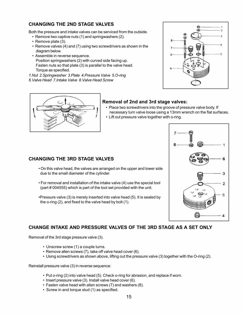
CHANGING THE 2ND STAGE VALVESBoth the pressure and intake valves can be serviced from the outside.
• Remove two captive nuts (1) and springwashers (2).• Remove plate (3).• Remove valves (4) and (7) using two screwdrivers as shown in the
diagram below.• Assemble in reverse sequence.
Position springwashers (2) with curved side facing up.Fasten nuts so that plate (3) is parallel to the valve head.Torque as specified.
1.Nut 2.Springwasher 3.Plate 4.Pressure Valve 5.O-ring6.Valve Head 7.Intake Valve 8.Valve Head Screw
Removal of 2nd and 3rd stage valves:• Place two screwdrivers into the groove of pressure valve body. If
necessary turn valve loose using a 13mm wrench on the flat surfaces.• Lift out pressure valve together with o-ring.
CHANGING THE 3RD STAGE VALVES
• On this valve head, the valves are arranged on the upper and lower sidedue to the small diameter of the cylinder.
• For removal and installation of the intake valve (4) use the special tool(part # 004555) which is part of the tool set provided with the unit.
•Pressure valve (3) is merely inserted into valve head (5). It is sealed bythe o-ring (2), and fixed to the valve head by bolt (1).
CHANGE INTAKE AND PRESSURE VALVES OF THE 3RD STAGE AS A SET ONLY
Removal of the 3rd stage pressure valve (3).
• Unscrew screw (1) a couple turns.• Remove allen screws (7), take off valve head cover (6).• Using screwdrivers as shown above, lifting out the pressure valve (3) together with the O-ring (2).
Reinstall pressure valve (3) in reverse sequence:
• Put o-ring (2) into valve head (5). Check o-ring for abrasion, and replace if worn.• Insert pressure valve (3). Install valve head cover (6).• Fasten valve head with allen screws (7) and washers (8).• Screw in and torque stud (1) as specified.

16
V-BELT TENSION ADJUSTMENT• Slightly loosen motor mounting nuts.
• Adjust motor until the v-belt tension is correct.
• Tighten motor mounting nuts.
• Run motor for approximately 5 minutes. Stop motor, check belt tension, and readjust if necessary.
• Check that after tension adjustment and tightening the motor mounting nuts, both pulleys are in a straightline to avoid excessive wear of the v-belt. Hold a straight edge against the compressor and motor pulleys asshown. Edge must touch the pulleys at four points, or you must re-adjust motor.
COOLING SYSTEM
• The cylinders of the compressor block, the intermediate coolers, and the after-cooler are all air cooled.
• For this purpose, the compressor is equipped with a fanwheel connected to the counter-weight at thecrankshaft end opposite to the V-belt pulley. It draws the cooling air through the fanwheel cover from thesurroundings.
• Refer to page 6 for specific ambient temperature data.
CHECKING THE DRIVE BELT
The best tension for belt drive is the lowest possible, while notslipping when under full load. This is best quantified by beltdepression with thumb pressure between the two pulleys, withthe belt deflecting ¼ “ (10mm) .
• Re-adjust v-belt after 25 hours of operation.
• Check the tension and adjust every 125 hours, assessingthe belt for wear or damage.

17
INTAKE FILTERThe intake filter is a dry micronic filter used to filter the intake air.
Filter Maintenance:Filter cartridge must be changed at regular intervalsaccording to maintenance schedule on page 12.
• Remove knurled nut (1) and take off plastic cap(2). Remove filter cartridge (3) and clean with abrush or by blowing air from the inside to out.
• Turn the cartridge 90º when replacing. Replace thedirty cartridge once it has been turned three timesand been used through the full system.
• Clean filter housing inside with a damp cloth. Takecare to prevent dust from entering the intake pipe.
• Replace o-ring (4) if damaged.
OIL LEVEL CHECKCheck oil level daily prior to operating compressor. Use thedipstick and a lint free cloth to check the oil, by wiping off oilseveral times. Note that the oil level must be between theminimum and maximum dipstick notches.
Add oil if necessary and recheck level. Oil should not exceedthe maximum level, as this could result in valves sooting up.
OIL TYPESUsing the correct oil is of utmost importance for proper care andmaintenance of the compressor, along with keeping the life and function of your compressor at its best.
Only use oils that:• are low in deposits• have no carbonizing effect, especially in the valves• have good anti-corrosive properties• provide emulsification of the condensate in the crankcase• are physiologically and toxicologically suitable
Due to the thermal load on the compressor, only high quality oil should be used. You are recommended to restrictoils to those which have been approved by the manufacturer and are in our list of oils (see page 11).
Synthetic Lube OilsFor operating under severe conditions such as continuous running and/or higher ambient temperatures, werecommend Part No. CF-2000 (Synthetic Compressor Lubricant, Food Grade). CF-2000 has been speciallyformulated for use in high pressure compressors and will provide optimal performance through a wide range ofconditions.
NOTE: The compressor systems are delivered with one liter of natural oil, Part No. BTLHPN-25.

18
3. The moisture indicator ring is placed into thewindow first. Minimal handling is best, and careshould be taken with the packaging contentsand their disposal. 4. This view shows the ring properly installed in
the window.
Inspect o-ring for wear, andreplace if worn.
Lube threads with food gradesilicone grease if needed.
1. Unscrew window cap in counter-clockwisedirection. (NOTE: The orientation of thesightglass assembly may vary.)
2. Here the cap is shown having been removed,and the retaining spring exposed. Oldelements are removed from the window atthis time.
WARNING: Make sure all pressure is relieved prior to changing element.
SIGHTGLASS CO MOISTURE ELEMENT CHANGE DEMONSTRATIONReplacement Element Part #M7414 (Assy # VM211-EL)

19
5. The CO monitoring disc is shown ready toinstall into the window. It is placed in and thencentered in the moisture indicator ring.
6. The spring is placed into the window, centered on the COdisc and the whole unit is then ready to be reassembled.
7. The cap is replaced and it is screwed backinto place, finger tight. Make sure the COdisc remains in place.
8. With change and reassembly completed, bothindicators are easily viewed in the window and thecap is tightened down.

20
3. Prepare Filter
• Uncover top plug by removingtape.
• Remove top plug with pliersusing rocking motion.
• Remove bottom plug.
Discarded Items:
4. Place New Filter
Place the new filter into the chamber seating iton the bottom.
BLACK FILTER CARTRIDGE REPLACEMENT DEMONSTRATIONREPLACEMENT CARTRIDGE PART #X53240
WARNING:Prior to changing the filter, purge all pressure using the bleeder valve.
1. Remove Cap
Counter-clockwise rotation of the cap using a wrenchas shown will loosen the cap for removal.
2. Remove Old Filter
While removing the old filter, check the Lifeband ™indicator to determine filter usage or replacement.

21
5. Prepare to replace cap
Inspect o-rings for damage and replace if necessary.Use a food grade silicone grease to lube threads andring if needed.
6. Replace Cap
Clockwise rotation of the cap using a wrench asshown will tighten the cap for replacement.
Figure 1 Black Filter Cartridge

22
GOLD FILTER TOWER CARTRIDGE REPLACEMENT DEMONSTRATION
1. Vent Pressure
Prior to changing the filter, purge all pressure usingthe bleeder valve. It may be necessary to ventexcess pressure by turning the small cap on thegold tower clockwise. After venting pressure, closecap by turning counter-clockwise.
2. Remove Cap
Insert rod tool into holes in cap andturn counter-clockwise.
3. Remove Old Filter
Remove old filter by pulling up on wire.
4. Prepare Filter
Pull plastic cap off of bottom plug of cartridgeand discard.

23
5. Install Cartridge
Insert new cartridge making sure to push down as far aspossible.
6. Lubricate O-ring
Inspect o-rings for damage and replace if necessary.Use a food grade silicone grease to lube threads andring if needed.
7. Replace Cap
Insert rod tool into holes and turn clockwise to tighten cap.
Replacement cartridge part number isX22679.
Figure 2 Gold Filter Cartridge

24
TANKFILL DEMONSTRATION
Tank Fill Whip Assemblies:Shown are the tankfill whip ends for DIN and Yoke systems.
A. Yoke connectorB. DIN connectorC. bleeder valveD. fill valve
B
C
D
1. Tank Attachment
• Open tank valve slightly to blow any moisture clear from fill opening.
• Connect tanks to fill whips using appropriate fittings (DIN, Yoke, or conversion adapters). Tighten only finger tight.
NOTE: Remember to check the system log before compressor use and to update the system log after you are done.
A
DC

25
2. Close Bleeder Valves
Clockwise rotation of the valve closes thebleeder valve.
3. Open Tank Valves
Counter-clockwise rotation of this valvewill open the tanks for filling.
4. Open Fill Valves
Counter-clockwise rotation of this valve will open theline to the tanks. The tanks will now equalize anydifferences in their pressures.
5. Start The Compressor
The indicator light will come on. If you have a dualpressure switch, be sure the control is in the correctposition.

26
NOTE: If you are filling more tanks, thecompressor may be left “ON”.
6. Close Fill Lines
Clockwise rotation of the knob closes off the filllines.
7. Close Tanks
Clockwise rotation of the knob closes the tankvalves.
8. Open Bleeder Valves
Counter-clockwise rotation of this valve willallow pressure to vent.
9. Remove Tanks
Disconnect tanks from the fill line. New tanksmay be attached at this time and the processrepeated.

27
1. Remove the dipstick.
2. Removing the oil plug as demonstrated using onewrench to hold the tube and fitting and another toloosen the plug.
3. Remove the plug and allow the oil to drain.Care should be taken in draining the oil into aproper container for disposal per localguidelines and laws.
4. Replace the oil plug again using a wrench tostabilize the drain and another one to secure theplug. Fill the unit with approved oil through thedipstick tube. Check the level with the dipstick andadd as necessary for proper levels.
OIL CHANGE DEMONSTRATION

28
Figure 3 Front and Back Compressor View
Figu
re 3
Fro
nt a
nd B
ack
Com
pres
sor
View
Fan
Cov
er
Man
ual D
rain
Val
ves
(nor
mal
ly c
lose
d)
TEFC
Mot
orH
eavy
Dut
ySt
ain
less
Ste
el F
ram
e
Out
let t
o C
ond
ensa
te
Dra
in R
eser
voir
Aut
omat
ic D
rain
Tim
ers
Oil
Dra
in
Out
let t
o Re
mot
e Fi
lter
Tow
eror
Fill
Man
ifold
Init
ial F
ilter
Tow
erw
ith
Inte
gra
ted
Saf
ety
Oil
Dip
stic
k/Fi
ll Tu
be
Air
Inta
ke F
ilter
Hou
sin
g
Belt
Gua
rd
Vib
rati
on Is
olat
ors
29
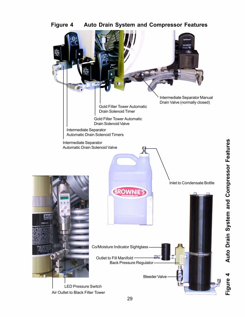
Outlet to Fill Manifold
Co/Moisture Indicator Sightglass
Bleeder Valve
Back Pressure Regulator
Figure 4 Auto Drain System and Compressor Features
Figu
re 4
Aut
o D
rain
Sys
tem
and
Com
pres
sor
Feat
ures
LED Pressure SwitchAir Outlet to Black Filter Tower
Inlet to Condensate Bottle
Intermediate Separator ManualDrain Valve (normally closed)
Intermediate SeparatorAutomatic Drain Solenoid Timers
Intermediate SeparatorAutomatic Drain Solenoid Valve
Gold Filter Tower AutomaticDrain Solenoid Valve
Gold Filter Tower AutomaticDrain Solenoid Timer

30
Parts Drawing 1
P
arts
Dra
win
g 1-
CR
AN
KC
ASE
, DR
IVIN
G G
EAR
AN
D F
AN
WH
EEL

31
Part
s D
raw
ing
11234567812345678123456781234567812345678123456781234567812345678123456781234567812345678123456781234567812345678123456781234567812345678123456781234567812345678123456781234567812345678123456781234567812345678123456781234567812345678123456781234567812345678123456781234567812345678123456781234567812345678123456781234567812345678123456781234567812345678123456781234567812345678123456781234567812345678123456781234567812345678123456781234567812345678123456781234567812345678123456781234567812345678123456781234567812345678123456781234567812345678123456781234567812345678123456781234567812345678123456781234567812345678123456781234567812345678123456781234567812345678123456781234567812345678123456781234567812345678123456781234567812345678123456781234567812345678123456781234567812345678123456781234567812345678123456781234567812345678123456781234567812345678123456781234567812345678123456781234567812345678123456781234567812345678123456781234567812345678123456781234567812345678123456781234567812345678123456781234567812345678123456781234567812345678123456781234567812345678123456781234567812345678123456781234567812345678123456781234567812345678123456781234567812345678123456781234567812345678123456781234567812345678123456781234567812345678123456781234567812345678123456781234567812345678123456781234567812345678123456781234567812345678123456781234567812345678123456781234567812345678123456781234567812345678123456781234567812345678#Q
TYPA
RT
#D
ESC
RIP
TIO
NN
OTE
S
1 07
8444
Driv
ing
Gea
r Ass
embl
y Ite
ms
2 - 9
24
SCR
-017
9Al
len
Scre
wM
8x30
DIN
912
37
N286
2W
ashe
r 8m
mDI
N734
94
161
374
Cou
nter
wei
ght
52
N488
9Ke
y3x
5 D
IN68
886
107
8447
Cra
nksh
aft A
ssem
bly
71
5947
0Th
rust
Was
her
81
6702
7V-
belt
Pulle
y9
1SC
R-0
136
Alle
n Sc
rew
M8x
20 D
IN91
210
5N5
8W
ashe
rB8
,4 D
IN12
511
159
397
Cove
r12
1N4
855
O-ri
ngØ
140
x213
2N3
702
Rol
ler B
earin
gØ
20x
Ø 5
2x15
141
0781
98C
rank
case
152
N286
1Sh
aft s
eal
A20x
Ø 4
7x7
161
1392
0Fa
n17
1SC
R-0
159
Alle
n Sc
rew
M8x
20 D
IN91
218
1W
AS-0
001
Split
Loc
k W
ashe
r 8
mm
DIN
127
191
N246
0W
ashe
r8m
m D
IN90
2120
1N2
04Pl
ug w
ith p
last
ic g
aske
tR
3/8
”x8
DIN
910
211
N842
Gas
ket
A 17
x24
x2 D
IN76
0322
1N
1568
8Pl
ugR
1/8
” DIN
908
231
N405
1G
aske
tA
10x1
5 D
IN76
0324
2SC
R-0
144
Alle
n Sc
rew
M6x
16 D
IN91
225
2N3
026
Wav
e W
ashe
r6m
m26
112
560
Pape
r Gas
ket
23x3
0x0.
5mm
271
6700
7O
il Fille
r28
1N3
951
O-ri
ngØ
12x
2.5
291
0670
13D
ip-s
tick
301
TUB-
R-00
38H
ose
DN
5, P
VC, 1
10m
m31
1N
2554
2O
il Pum
p32
178
346
Gas
ket
336
N25
542
Hex
Hea
d Sc
rew
M4x
35 D
IN24
014

32
P
arts
Dra
win
g 2
- PIS
TON
S A
ND
CYL
IND
ERS
Parts Drawing 2

33
Part
s D
raw
ing
21234567812345678123456781234567812345678123456781234567812345678123456781234567812345678123456781234567812345678123456781234567812345678123456781234567812345678123456781234567812345678123456781234567812345678123456781234567812345678123456781234567812345678123456781234567812345678123456781234567812345678123456781234567812345678123456781234567812345678123456781234567812345678123456781234567812345678123456781234567812345678123456781234567812345678123456781234567812345678123456781234567812345678123456781234567812345678123456781234567812345678123456781234567812345678123456781234567812345678123456781234567812345678123456781234567812345678123456781234567812345678123456781234567812345678123456781234567812345678123456781234567812345678123456781234567812345678123456781234567812345678123456781234567812345678123456781234567812345678123456781234567812345678123456781234567812345678123456781234567812345678123456781234567812345678123456781234567812345678123456781234567812345678123456781234567812345678123456781234567812345678123456781234567812345678123456781234567812345678123456781234567812345678123456781234567812345678123456781234567812345678123456781234567812345678123456781234567812345678123456781234567812345678123456781234567812345678123456781234567812345678123456781234567812345678123456781234567812345678123456781234567812345678123456781234567812345678123456781234567812345678123456781234567812345678123456781234567812345678 #Q
TY P
AR
T#
D
ESC
RIP
TIO
NN
OTE
S
1 2
NUT-
0118
Hex
Nut
, Sel
f Loc
king
M6
DIN
985-
82
4W
AS-0
024
Flat
Was
her
6mm
DIN
125B
-ST
34
N461
5St
udM
6x70
DIN
835
41
6135
4C
ylin
der,
2nd
Stag
e5
1N3
157
O-ri
ngØ
31.
47x
1.78
61
0699
202n
d St
age
Pist
on A
ssy
74
N15
294
Circ
lipJ9
.5x1
82
6090
4Pi
ston
Pin
91
6090
02n
d St
age
Pist
on10
1N
1581
6Pi
ston
Rin
g Se
tØ
28m
m11
106
9927
3rd
Stag
e Pi
ston
Ass
y12
1 6
1370
Gui
de P
isto
n13
1N4
868
O-ri
ngØ
33.
05x1
.78
141
6709
6C
ylin
der,
3rd
Stag
eØ
12m
m15
6N
1569
1St
udM
6x20
DIN
835
161
0753
10Pi
ston
and
Sle
eve
Assy
171
N23
810
Pist
on R
ing
Set
181
N250
7O
-ring
Ø 1
8.77
x1.7
819
107
3906
1st S
tage
Pis
ton
Assy
202
N103
3C
irclip
J14x
1.0m
m D
IN47
221
1N
1744
0Pi
ston
Pin
14x9
x52m
m D
IN73
126
221
6702
81s
t Sta
ge P
isto
n60
x3x1
4mm
231
N385
6Pi
ston
Rin
g Se
tØ
60
241
N494
8O
-ring
Ø 7
2.75
x1.7
825
1 7
8455
Cyl
inde
r 1st
Sta
geØ
60m
m26
2 6
7518
Hex
Bus
hing
6mm
27 4
N15
495
Stud
M6
x 60

34
12345678123456781234567812345678123456781234567812345678123456781234567812345678123456781234567812345678123456781234567812345678123456781234567812345678123456781234567812345678123456781234567812345678123456781234567812345678123456781234567812345678123456781234567812345678123456781234567812345678123456781234567812345678123456781234567812345678123456781234567812345678123456781234567812345678123456781234567812345678123456781234567812345678123456781234567812345678123456781234567812345678123456781234567812345678123456781234567812345678 N
OD
ESIG
NAT
ION
PAR
T N
O.
Parts Drawing 3
P
arts
Dra
win
g 3
1In
take
Filt
er A
ssy
0593
77 2
Knur
led
Nut
N487
0 3
Filte
r Cap
5943
3 4
Filte
r Car
tridg
eN4
823
5H
ex N
utN2
87 6
Was
her
N331
3 7
O-ri
ngN4
877
8Fi
lter S
uppo
rt59
434
9G
aske
t65
985
10
Hos
eN
1744
2 1
1Te
lesc
opic
Inta
ke T
ube
0620
80 1
2In
term
edia
te S
epar
ator
A.
0699
34 1
3Fi
lter H
ead
Assy
0699
33 1
4D
rain
Tap
Ass
y06
5500
15
Gas
ket
4479
16
Hol
low
Bol
t61
364
17
Filte
r Ins
ert
N15
705
18
Cou
plin
g N
ut61
975
19
O-ri
ngN3
556
20
Filte
r Hou
sing
6136
1 2
1Th
read
ed C
olla
r13
937
22
Gas
ket
240
23
Mal
e El
bow
N106
5 2
4M
ale
Run
TN
1633
4 2
5H
ose
N17
073
26
Safe
ty V
alve
2nd
Stg
0128
86 2
7G
aske
t64
498

35
Figure 5 Black Filter Tower
Figu
re 5
B
lack
Filt
er T
ower

36
TROUBLESHOOTING
Warning:Compressor repairs are to be performed by an authorized dealer/service center only. Any repairs madeby the user are to be made at the user’s own risk and will void Brownie’s Third Lung warranty unless theuser has been authorized to make a repair and has been given appropriate repair instructions. Repairsmust never be carried out without sufficient knowledge and understanding of compressor technology. Ifyou have any questions or are unsure of a problem’s cause, contact our Service Department for adviceprior to disassembly of the unit or component parts.
PROBLEM CAUSE ACTION
Unit does not start a) Power off a) Check breakerb) Loose electrical connections b) Check electrical connections & retightenc) Bad internal fuse c) Check electrical legs for proper voltage
and replace fuse if necessaryd) Overload in motor activated d) Press reset button
Not automatically draining a) Line valve closed a) Make sure line valve is fully open(ACD does not operate b) Loose electrical terminal b) Make sure connections are tight atproperly) at solenoid solenoid
c) Bad solenoid c) Remove and replace solenoidd) Bad drain timer d) Replace drain timer
Compressor does not reach a) Leak in tubing or Automatic a) Tighten all threaded attachments andfinal pressure Condensate Drain connectors.
b) Final pressure safety valve b) Replace safety valve blows too soon (defective)c) Unloader valve needs service c) Service unloader valve
Pressure Relief valves of a) Intermediate pressures too high a) Check intake valve of next stage:1st and 2nd Stages engage Clean it (replace if necessary)
b) Pressure relief valve leaking b) Replace pressure relief valvec) Check valve bad on ACD c) Replace check valve on ACD
Air delivery rate decreases a) piston rings worn out a) Replace piston ringsb) 1st stage valve leaking b) Replace intake valvec) Intake filter soiled c) Clean or replace filterd) Pipe coupling leaking d) Retighten couplingse) Excessive wear of 3rd stage e) Replace piston and sleeve of 3rd stage pistonf) Drive belt slipping f) Tighten or replace drive belt
NOTE: Troubleshooting of electrical problems may require the use of a multimeter with AC capability.

37
PROBLEM CAUSE ACTION
Intermediate pressure safety a) Intermediate pressure too a) Check / replace inlet or pressure valvevalve blows high due to defective inlet
or pressure valve of the next stageb) Safety valve leaking b) Replace safety valve
Any taste in air a) Filter cartridge saturated a) Replace cartridgeb) Unqualified lubricant being b) Replace oil with an approved brand used
c) Air Test (contact our Service Dept for kit)
Compressor overheats a) Insufficient cooling air a) Inlet and pressure valve of one stage leaking: direction of rotation incorrect
b) Ambient temp. too high b) Check location, ventilation for max +100º F (+38º C)
c) Direction of rotation wrong c) Check / correct rotationd) Inlet/pressure valves on one d) Check valves, clean or replace stage leak
Unit cannot be switched off a) Turn breaker offb) Call Brownie’s for technical advice
Unit runs rough a) Drive belt worn out a) Replace drive beltand/or vibrates b) Drive belt loose b) Tighten drive belt
If you encounter a problem that cannot be solved with this troubleshooting guide, please contact an authorizedBrownie’s Third Lung Service Center. In the case of problems with the electrical system, consult a qualifiedelectrician for repairs.
When you call for service or technical advice, please have the following information:a) unit serial number and/or model numberb) hours of operation

38
Oil Level Purification CO Sightglass Air Intake Oil Level Purification CO Sightglass Air Intake Oil Level Purification CO Sightglass Air Intake Oil Level Purification CO Sightglass Air Intake Oil Level Purification CO Sightglass Air Intake Oil Level Purification CO Sightglass Air Intake Oil Level Purification CO Sightglass Air Intake Oil Level Purification CO Sightglass Air Intake Oil Level Purification CO Sightglass Air Intake
123456789012345678901234567890121234567890123456789012345678901212345678901234567890123456789012123456789012345678901234567890121234123456789012345678901234567890121234567890123456789012345678901212345678901234567890123456789012123456789012345678901234567890121234123456789012345678901234567890121234567890123456789012345678901212345678901234567890123456789012123456789012345678901234567890121234123456789012345678901234567890121234567890123456789012345678901212345678901234567890123456789012123456789012345678901234567890121234123456789012345678901234567890121234567890123456789012345678901212345678901234567890123456789012123456789012345678901234567890121234123456789012345678901234567890121234567890123456789012345678901212345678901234567890123456789012123456789012345678901234567890121234123456789012345678901234567890121234567890123456789012345678901212345678901234567890123456789012123456789012345678901234567890121234123456789012345678901234567890121234567890123456789012345678901212345678901234567890123456789012123456789012345678901234567890121234123456789012345678901234567890121234567890123456789012345678901212345678901234567890123456789012123456789012345678901234567890121234123456789012345678901234567890121234567890123456789012345678901212345678901234567890123456789012123456789012345678901234567890121234123456789012345678901234567890121234567890123456789012345678901212345678901234567890123456789012123456789012345678901234567890121234
Yacht Pro Systems Operation LogNOTE: Check Maintenance Log for Service Intervals with each operation
DATE HOURS Operator Checks Maintenance Performed& Comments
KEEP THIS LOG MAINTAINED!!!Brownie’s recommends making copies of these blank pages for future use. Completed pagesshould be copied and kept in a safe place.

39
Oil Level Purification CO Sightglass Air Intake Oil Level Purification CO Sightglass Air Intake Oil Level Purification CO Sightglass Air Intake Oil Level Purification CO Sightglass Air Intake Oil Level Purification CO Sightglass Air Intake Oil Level Purification CO Sightglass Air Intake Oil Level Purification CO Sightglass Air Intake Oil Level Purification CO Sightglass Air Intake Oil Level Purification CO Sightglass Air Intake
123456789012345678901234567890121234567890123456789012345678901212345678901234567890123456789012123456789012345678901234567890121234123456789012345678901234567890121234567890123456789012345678901212345678901234567890123456789012123456789012345678901234567890121234123456789012345678901234567890121234567890123456789012345678901212345678901234567890123456789012123456789012345678901234567890121234123456789012345678901234567890121234567890123456789012345678901212345678901234567890123456789012123456789012345678901234567890121234123456789012345678901234567890121234567890123456789012345678901212345678901234567890123456789012123456789012345678901234567890121234123456789012345678901234567890121234567890123456789012345678901212345678901234567890123456789012123456789012345678901234567890121234123456789012345678901234567890121234567890123456789012345678901212345678901234567890123456789012123456789012345678901234567890121234123456789012345678901234567890121234567890123456789012345678901212345678901234567890123456789012123456789012345678901234567890121234123456789012345678901234567890121234567890123456789012345678901212345678901234567890123456789012123456789012345678901234567890121234123456789012345678901234567890121234567890123456789012345678901212345678901234567890123456789012123456789012345678901234567890121234123456789012345678901234567890121234567890123456789012345678901212345678901234567890123456789012123456789012345678901234567890121234
Yacht Pro Systems Operation LogNOTE: Check Maintenance Log for Service Intervals with each operation
DATE HOURS Operator Checks Maintenance Performed& Comments
KEEP THIS LOG MAINTAINED!!!Brownie’s recommends making copies of these blank pages for future use. Completed pagesshould be copied and kept in a safe place.

40
Oil Level Purification CO Sightglass Air Intake Oil Level Purification CO Sightglass Air Intake Oil Level Purification CO Sightglass Air Intake Oil Level Purification CO Sightglass Air Intake Oil Level Purification CO Sightglass Air Intake Oil Level Purification CO Sightglass Air Intake Oil Level Purification CO Sightglass Air Intake Oil Level Purification CO Sightglass Air Intake Oil Level Purification CO Sightglass Air Intake
123456789012345678901234567890121234567890123456789012345678901212345678901234567890123456789012123456789012345678901234567890121234123456789012345678901234567890121234567890123456789012345678901212345678901234567890123456789012123456789012345678901234567890121234123456789012345678901234567890121234567890123456789012345678901212345678901234567890123456789012123456789012345678901234567890121234123456789012345678901234567890121234567890123456789012345678901212345678901234567890123456789012123456789012345678901234567890121234123456789012345678901234567890121234567890123456789012345678901212345678901234567890123456789012123456789012345678901234567890121234123456789012345678901234567890121234567890123456789012345678901212345678901234567890123456789012123456789012345678901234567890121234123456789012345678901234567890121234567890123456789012345678901212345678901234567890123456789012123456789012345678901234567890121234123456789012345678901234567890121234567890123456789012345678901212345678901234567890123456789012123456789012345678901234567890121234123456789012345678901234567890121234567890123456789012345678901212345678901234567890123456789012123456789012345678901234567890121234123456789012345678901234567890121234567890123456789012345678901212345678901234567890123456789012123456789012345678901234567890121234123456789012345678901234567890121234567890123456789012345678901212345678901234567890123456789012123456789012345678901234567890121234
Yacht Pro Systems Operation LogNOTE: Check Maintenance Log for Service Intervals with each operation
DATE HOURS Operator Checks Maintenance Performed& Comments
KEEP THIS LOG MAINTAINED!!!Brownie’s recommends making copies of these blank pages for future use. Completed pagesshould be copied and kept in a safe place.

41
Oil Level Purification CO Sightglass Air Intake Oil Level Purification CO Sightglass Air Intake Oil Level Purification CO Sightglass Air Intake Oil Level Purification CO Sightglass Air Intake Oil Level Purification CO Sightglass Air Intake Oil Level Purification CO Sightglass Air Intake Oil Level Purification CO Sightglass Air Intake Oil Level Purification CO Sightglass Air Intake Oil Level Purification CO Sightglass Air Intake
123456789012345678901234567890121234567890123456789012345678901212345678901234567890123456789012123456789012345678901234567890121234123456789012345678901234567890121234567890123456789012345678901212345678901234567890123456789012123456789012345678901234567890121234123456789012345678901234567890121234567890123456789012345678901212345678901234567890123456789012123456789012345678901234567890121234123456789012345678901234567890121234567890123456789012345678901212345678901234567890123456789012123456789012345678901234567890121234123456789012345678901234567890121234567890123456789012345678901212345678901234567890123456789012123456789012345678901234567890121234123456789012345678901234567890121234567890123456789012345678901212345678901234567890123456789012123456789012345678901234567890121234123456789012345678901234567890121234567890123456789012345678901212345678901234567890123456789012123456789012345678901234567890121234123456789012345678901234567890121234567890123456789012345678901212345678901234567890123456789012123456789012345678901234567890121234123456789012345678901234567890121234567890123456789012345678901212345678901234567890123456789012123456789012345678901234567890121234123456789012345678901234567890121234567890123456789012345678901212345678901234567890123456789012123456789012345678901234567890121234123456789012345678901234567890121234567890123456789012345678901212345678901234567890123456789012123456789012345678901234567890121234
Yacht Pro Systems Operation LogNOTE: Check Maintenance Log for Service Intervals with each operation
DATE HOURS Operator Checks Maintenance Performed& Comments
KEEP THIS LOG MAINTAINED!!!Brownie’s recommends making copies of these blank pages for future use. Completed pagesshould be copied and kept in a safe place.

42
Oil Level Purification CO Sightglass Air Intake Oil Level Purification CO Sightglass Air Intake Oil Level Purification CO Sightglass Air Intake Oil Level Purification CO Sightglass Air Intake Oil Level Purification CO Sightglass Air Intake Oil Level Purification CO Sightglass Air Intake Oil Level Purification CO Sightglass Air Intake Oil Level Purification CO Sightglass Air Intake Oil Level Purification CO Sightglass Air Intake
123456789012345678901234567890121234567890123456789012345678901212345678901234567890123456789012123456789012345678901234567890121234123456789012345678901234567890121234567890123456789012345678901212345678901234567890123456789012123456789012345678901234567890121234123456789012345678901234567890121234567890123456789012345678901212345678901234567890123456789012123456789012345678901234567890121234123456789012345678901234567890121234567890123456789012345678901212345678901234567890123456789012123456789012345678901234567890121234123456789012345678901234567890121234567890123456789012345678901212345678901234567890123456789012123456789012345678901234567890121234123456789012345678901234567890121234567890123456789012345678901212345678901234567890123456789012123456789012345678901234567890121234123456789012345678901234567890121234567890123456789012345678901212345678901234567890123456789012123456789012345678901234567890121234123456789012345678901234567890121234567890123456789012345678901212345678901234567890123456789012123456789012345678901234567890121234123456789012345678901234567890121234567890123456789012345678901212345678901234567890123456789012123456789012345678901234567890121234123456789012345678901234567890121234567890123456789012345678901212345678901234567890123456789012123456789012345678901234567890121234123456789012345678901234567890121234567890123456789012345678901212345678901234567890123456789012123456789012345678901234567890121234
Yacht Pro Systems Operation LogNOTE: Check Maintenance Log for Service Intervals with each operation
DATE HOURS Operator Checks Maintenance Performed& Comments
KEEP THIS LOG MAINTAINED!!!Brownie’s recommends making copies of these blank pages for future use. Completed pagesshould be copied and kept in a safe place.

43
Oil Level Purification CO Sightglass Air Intake Oil Level Purification CO Sightglass Air Intake Oil Level Purification CO Sightglass Air Intake Oil Level Purification CO Sightglass Air Intake Oil Level Purification CO Sightglass Air Intake Oil Level Purification CO Sightglass Air Intake Oil Level Purification CO Sightglass Air Intake Oil Level Purification CO Sightglass Air Intake Oil Level Purification CO Sightglass Air Intake
123456789012345678901234567890121234567890123456789012345678901212345678901234567890123456789012123456789012345678901234567890121234123456789012345678901234567890121234567890123456789012345678901212345678901234567890123456789012123456789012345678901234567890121234123456789012345678901234567890121234567890123456789012345678901212345678901234567890123456789012123456789012345678901234567890121234123456789012345678901234567890121234567890123456789012345678901212345678901234567890123456789012123456789012345678901234567890121234123456789012345678901234567890121234567890123456789012345678901212345678901234567890123456789012123456789012345678901234567890121234123456789012345678901234567890121234567890123456789012345678901212345678901234567890123456789012123456789012345678901234567890121234123456789012345678901234567890121234567890123456789012345678901212345678901234567890123456789012123456789012345678901234567890121234123456789012345678901234567890121234567890123456789012345678901212345678901234567890123456789012123456789012345678901234567890121234123456789012345678901234567890121234567890123456789012345678901212345678901234567890123456789012123456789012345678901234567890121234123456789012345678901234567890121234567890123456789012345678901212345678901234567890123456789012123456789012345678901234567890121234123456789012345678901234567890121234567890123456789012345678901212345678901234567890123456789012123456789012345678901234567890121234
Yacht Pro Systems Operation LogNOTE: Check Maintenance Log for Service Intervals with each operation
DATE HOURS Operator Checks Maintenance Performed& Comments
KEEP THIS LOG MAINTAINED!!!Brownie’s recommends making copies of these blank pages for future use. Completed pagesshould be copied and kept in a safe place.

44
NOTES:

RL1Type
PI84-24DC-M41G
BARKSDALEPressure Switch
UDS7UL
A1 A2
OPTIMUMDrain Valve
5000psi1
OPTIMUMDrain Valve
5000psi2
Brownie's Standard Connection Diagram ForMA7200
24VG
MA7200Terminal Arrangement
R/L1
S/L2
T/L3
_ B1/P
B2U/T1
V/T2
W/T3
Hour Meters98200 Series
Motor
11
14
1
2&3
4
GroundingLead
R2AR2C
1 3 5 A(-)
S(-)GND+24V8E 2 R1C
12 22
21
24
F1 FUSE250VAC/5A
1
2
3
4
56
7
8
9
(GREEN WITH BLACK)
(WHITE)
(RED WITH BLACK)
TemperatureSwitch
FENWAL 08L320F
(WHITE)
Note: The shapes that are not rectangles are located outside of the MA7200 unite. See diagram for location of each of the sensors in the system.The arrows with numbers represent the wires leading to the yellow connector described below;Within the parenthesis is the real color of the wires.
L1 L2
24VDC
6
DSP 10-24240VAC/24VDC

Yellow Cable
1.Green with Black(drain valv. L1) Pin42.White with Black(pin2&3. press. switch) Pin83.Orange(pin4. press. switch 24v) Pin14.White (T1) Pin55.Red (T2) Pin66.Red with Black (T3) Pin37.Green (ground. lead) Pin78.Blue (pin 1. press. switch) Pin29.Black (drain valv. L2) Pin9
Frequency Drive
1.Green with Black2.Brown3.Orange4.White5.Red6.Red with Black7.Green8.Blue9.Black
To
CONNECTIONS FROM FREQUENCY DRIVE TO YELLOW CABLE& YELLOW CABLE TO YACHT PRO COMPRESSOR
Gray Cable on Compressor
1.White (drain valv.L1)2.Brown (pin2&3. press. switch)3.Red pin4. press. switch 24V)4.Yellow (T1 motor)5.Yellow T2 motor)6.Yellow (T3 motor)7.Green (ground lead)8.Blue (pin1. press. switch)9.Black (drain valv. L2)
To
1
2
34
5
6
7
89
PIN1-OrangePin2-BluePin3-Red/BlackPin4-Green/BlackPin5-WhitePin6-RedPin7-GreeanPin8-White/BlackPin9-Black
Yellow Cable
1.Green with Black(drain valv. L1) Pin42.White with Black(pin2&3. press. switch) Pin83.Orange(pin4. press. switch 24v) Pin14.White (T1) Pin55.Red (T2) Pin66.Red with Black (T3) Pin37.Green (ground. lead) Pin78.Blue (pin 1. press. switch) Pin29.Black (drain valv. L2) Pin9

User manual EDS 8000 US Page 3
Status 09.09.2009 HYDAC ELECTRONIC GMBH Part No. 669820
1 Safety Information Before commissioning,
- check the instrument and any accessories supplied - read the operating instructions - ensure that the instrument is suitable for your application.
If the instrument is not handled correctly, or if the operating instructions and specifications are not adhered to, damage to property or personal injury can result.
2 Functions of the EDS 8000 Depending on which model you have, the instrument offers the following functions:
Display of the actual pressure in psi, Mpa or bar Switching of the switch outputs in accordance with the pressure and the pre-set switching parameters Menu navigation in accordance with the VDMA standard 24574-1 Coloured LED backlight indicates the switching status
3 Installation The EDS 8000 can be mounted directly via the pressure connection or indirectly on a hydraulic block using a hose or a minimess line (for torque value, see Chapter 9 - Technical specifications). For optimum alignment, we recommend connecting the EDS 8000 mechanically using a rotating adapter (for Mechanical Accessories see Chapter 12.2). The electrical connection must be carried out by a qualified electrician according to the relevant regulations of the country concerned (VDE 0100 in Germany). The housing of the pressure switch must be properly earthed. When fitting into a hydraulic block, it is sufficient if the block is earthed via the hydraulic system. When installing with a minimess hose, the housing must be earthed separately (e.g. with a screened cable).
CAUTION: The EDS 8000 must be fitted using a suitable open-end wrench (across flats 27) on the hexagon nut of the pressure connection. Do not install the EDS 8000 by gripping the housing, as this would damage the housing or the entire instrument.
Additional installation suggestions which, from experience, reduce the effect of electromagnetic interference:
Make line connections as short as possible Use screened cabling (e.g. LIYCY 4 x 0.5 mm²) The cable screening must be fitted by qualified personnel subject to the ambient conditions and with the aim of suppressing interference Keep the unit well away from the electrical supply lines of power equipment, as well as from any electrical or electronic equipment causing interference
Status 09.09.2009 HYDAC ELECTRONIC GMBH Part No. 669820
Electronic Pressure Switch EDS 8000 (Menu navigation according to VDMA) User Manual (Translation of original instructions)
Status 09.09.2009 HYDAC ELECTRONIC GMBH Part No. 669820
Electronic Pressure Switch EDS 8000 (Menu navigation according to VDMA) User Manual (Translation of original instructions)
Electronic Pressure SwitchEDS 8000

User manual EDS 8000 US Page 4
Status 09.09.2009 HYDAC ELECTRONIC GMBH Part No. 669820
4 Controls of the EDS 8000
2 keys ( and E) for adjusting the switch points, switch-back points and additional functions 4-digit digital display LED backlight to indicate switch points (red = active / green = inactive)
Use the keys to select the next menu point, or alternatively to adjust the values.
To scroll through the menu
To increase the value
Hold the key down to fast-scroll through the parameter values
To select the menu point
To confirm value
5 Digital display Once the power supply has been switched on, the device briefly flashes "EdS", and then begins to show the actual pressure.
To check the unit of measurement being used for the pressure indication, press the right-hand key. Depending on the setting, bar, psi or MPa will be shown. The backlight changes colour according to the settings of the switch outputs and their switch points, i.e. when the switch output is inactive or low-level, the relevant backlight is "green", when the switch output is active or high-level, the relevant backlight is "red". Backlight Backlight for switching output 1 for switching output 2
E
E

User manual EDS 8000 US Page 5
Status 09.09.2009 HYDAC ELECTRONIC GMBH Part No. 669820
Reading the digital display
Description Representation on 7-segment display ASCII representation
Switch point, output 1 sp1 SP1 Switch-back point, output 1 rp1 RP1 Switch point, output 2 sp2 SP2 Switch-back point, output 2 rp2 RP2 Pressure window upper value, output 1 fk1 FH1 Pressure window lower value, output 1 fl1 FL1 Pressure window upper value, output 2 fk2 FH2 Pressure window lower value, output 2 fl2 FL2 Extended functions ef EF Reset res RES Switch delay time, output 1 ds1 dS1 Switch delay time, output 2 ds2 dS2 Switch-back delay time, output 1 dr1 dR1 Switch-back delay time, output 2 dr2 dR2 Output 1 ov1 Ou1 Output 2 ov2 Ou2 Normally open when hysteresis function is active
kno HNO
Normally open when window function is active
fno FNO
Normally closed when hysteresis function is active
knc HNC
Normally closed when window function is active
fnc FNC
Unit conversion uni Uni Units in bar bar Bar Units in MPa mpa MPa Units in psi psi psi Maximum value ki HI Error indication err ERR Delete --- --- Extended functions ef EF Yes yes Yes No no No Version Uer Ver

User manual EDS 8000 US Page 6
Status 09.09.2009 HYDAC ELECTRONIC GMBH Part No. 669820
NOTE:
If the actual pressure exceeds the instrument's nominal pressure it can no longer be displayed. The nominal pressure flashes in the display. As a result, when the menu point Max Value (Hi) is selected, the value of the highest measured pressure which has been stored flashes until the instrument is reset (rES).
If the actual pressure is less than 0.6 % of the nominal range, 0 bar is displayed.

User manual EDS 8000 US Page 7
Status 09.09.2009 HYDAC ELECTRONIC GMBH Part No. 669820
6 Output function
6.1 Switching Outputs The EDS 8000 has 2 switching outputs. The following settings can be made under the basic settings:
6.1.1 Switch point setting (SP) One switch point and one switch-back point can be set for each switching output. The particular output will switch when the set switch point is reached and switch back when the pressure drops below the switch-back point. Example for switch point 1 (normally closed and normally open function):
Abbreviations: "SP1", "SP2" = switch point 1 / switch point 2 "RP1", "RP2" = switch-back point 1 / switch-back point 2 "HNO", = normally open when hysteresis function is active "HNC" = normally closed when hysteresis function is active
NOTE: It is only possible to set the switch point (SP) if it is higher than the respective switch-back point (RP). In the case of low SPs we recommend setting the RP first.
6.1.2 Window function setting (Fno / Fnc) The window function allows you to monitor a range. An upper and a lower switch value can be entered for each switch output. These values determine the range. The relevant output will then switch when the pressure enters this range. When the pressure leaves this range, i.e. when the switch-back point has been reached, the output switches back. The lower switch-back value is just below the lower switch value. The upper switch-back value is just above the upper switch value. The range between the switch value and the switch-back value forms a safety margin which prevents unwanted switching operations from being triggered (such as those triggered by the pulsations of a pump).
OnNormally open function
Off
OnNormally closed function
Off

User manual EDS 8000 US Page 8
Status 09.09.2009 HYDAC ELECTRONIC GMBH Part No. 669820
Example for switch output 1 (normally closed and normally open function):
Abbreviations: "FH1", "FH2" = upper switch value 1 / upper switch value 2
"FL1", "FL2" = lower switch value 1 / lower switch value 2 "FNO" = normally open when window function is active "FNC" = normally closed when window function is active
NOTE: It is only possible to set the switch point (SP) if it is higher than the respective switch-back point (RP). In the case of low SPs we recommend setting the RP first. The window function only works properly (switching on and off) if all switch values (including the safety margin) are above 0 bar and below the nominal pressure range.
6.2 Setting ranges for the switching outputs Measuring range
Lower limit of RP / FL
Upper limit of SP / FH
Min. difference between RP and SP or FL and FH
Increment
in psi in bar in psi in bar in psi in bar in psi in bar in psi in bar 0 .. 500 0.. 25 5 0,25 500 25 5 0,25 1 0,05 0 ..1000 0.. 40 10 0,40 1000 40 10 0,40 2 0,10 0 ..3000 0 ..100 30 1,00 3000 100 30 1,00 5 0,20 0 ..6000 0 ..250 60 2,50 6000 250 60 2,50 10 0,50 0 ..9000 0 ..400 90 4,00 9000 400 90 4,00 20 1,00
0 ..600 6,00 600 6,00 1,00 * All ranges given in the table can be adjusted by the increments shown.
Rückschaltwert Schaltwert
Schaltwert Rückschaltwert Sicherheitszone
Sicherheitszone
Ein Aus
FL1 minus 0,4%FS FL1
FH1
t
P
Ein Ein
Aus
Aus
Ein Aus
FNO
FNC
Schlie ßerfunktion
Ö ffnerfunktion
Rückschaltwert Schaltwert
Schaltwert Rückschaltwert Sicherheitszone
Sicherheitszone
Ein Aus
FL1
FH1
t
P
Ein Ein
Aus
Aus
Ein Aus
FNO
FNC
Schlie ßerfunktion
Ö ffnerfunktion
FH1 plus 0,4%FS
OnNormally open function
Off
OnNormally closed function
Off
Reverse switch point Switch point
Switch point Reverse switch point
Safety zone
Safety zone
Off
On
On
Off

User manual EDS 8000 US Page 9
Status 09.09.2009 HYDAC ELECTRONIC GMBH Part No. 669820
7 Menu navigation The EDS 8000 can be adapted to suit the particular application as required by changing multiple settings. These settings are combined in a single menu.
NOTE: If no key is pressed for approx. 60 seconds, the menu closes automatically, and any changes that may have been made will not be saved. If both keys are pressed at the same time, the menu closes automatically and any changes made are saved. When an adjusted parameter is confirmed, the set value is displayed for a second before returning to the relevant menu point.
7.1 Main menu
Extendedfunctions

User manual EDS 8000 US Page 10
Status 09.09.2009 HYDAC ELECTRONIC GMBH Part No. 669820
7.2 Extended functions

User manual EDS 8000 US Page 11
Status 09.09.2009 HYDAC ELECTRONIC GMBH Part No. 669820
8 Error message If an error is detected, a corresponding error message appears that must be acknowledged by pressing any key. Possible error messages:
E.10 A data error was detected in the saved settings. This could be due to strong electromagnetic interference or a component fault.
Action: Press and confirm "RES" by pressing "Yes". The factory settings will be
restored for all adjustable parameters and all minimum and maximum values will be deleted. Enter the data again from the beginning.
E.12 An error was detected in the saved calibration data. This could be due to
strong electromagnetic interference or a component fault. Action: Disconnect then reconnect the supply voltage to the instrument. If the error
persists, the instrument must be returned to the factory for recalibration or repair.
E.21 A communication error was detected within the instrument. This could be due
to strong electromagnetic interference or a component fault. Solution: Press . If the error persists, disconnect then reconnect the supply voltage
to the instrument. If the error still persists, please contact our service department.
9 Pin assignment
Version with 2 switch outputs:
Male 4 pole, M12x1
EDS 8446-2
250 mA
250 mA
E
E
EDS 84x6-2

User manual EDS 8000 US Page 12
Status 09.09.2009 HYDAC ELECTRONIC GMBH Part No. 669820
10 Technical specifications Input data Measuring ranges 500; 1000; 3000; 6000; 9000 psi
25; 40; 100; 250; 400; 600 bar Overload pressures 1160; 2900; 7250; 11600; 14500 psi
80; 80; 200; 500; 800; 1000 bar Burst pressure 2900; 7250; 14500; 29000; 29000 psi
200; 200; 500; 1000; 2000; 2000 bar Mechanical connection SAE 6 9/16-18UNF2A; G1/4 A DIN 3852, Form ETorque value 15 lb-ft (20 Nm) Parts in contact with fluid: Mechanical connection: stainless steel
Sensor cell: stainless steel Seal: FPM
Output data Accuracy to DIN 16086, Max. setting (Display)
± 0.5 % FS typ. ± 1 % FS max.
Repeatability ± 0.5 % FS max. Temperature drift ± 0.017 % FS / °F [0.03 % / °C] max. zero point
± 0.017 % FS / °F [0.03 % / °C] max. range Long-term stability ± 0.25 % FS / year max. Switch outputs Type 2 PNP transistor outputs Switching current max. 250 mA per switching output Switching cycles > 100 million Reaction time < 10 ms Ambient Conditions Compensated temperature range -13 .. +185 °F [-25 .. + 85 °C] Operating temperature range * -13 .. +212 °F [-25 .. + 100 °C] Storage temperature range -40 .. +185 °F [-40 .. + 85 °C] Fluid temperature range * -13 .. +257 °F [-25 .. + 125 °C] Nominal temperature range of display (read-out)
+5 .. +185 °F [-15 .. + 70 °C]
mark EN 61000-6-1 / 2 / 3 / 4 Vibration resistance to DIN EN 60068-2-6 at 0 .. 500 Hz
approx. 10 g
Shock resistance to DIN EN 60068-2-29 (11 ms)
approx. 50 g
Protection class to DIN 40050 IP 67 (when an IP 67 connector is used) Other data Supply voltage 9.6 .. 32 V DC Current consumption max. 35 mA
(inactive switch output) Display: 4-digit, LED, 7-segment,
Height of digits 4.5 mm Life expectancy > 10 million cycles (0 .. 100 %) Weight: approx. 70 g
FS (Full Scale) = relative to the complete measuring range * extended temperature range possible. By separate request.

WHEN INSTALLING THE ELECTRONIC DRAIN VALVE MAKE SURE: •••• POWER IS TURNED OFF •••• AIR SYSTEM IS DRAINED (ZERO PRESSURE)
INSTALLATION • Verify flow direction. (stamped on valve body) • Valve can be mounted in any position. • Install a condensate drain on the outlet side of drain valve for proper collection and drainage of condensate. • If tubing is used for draining, Beware of “Whipping” when valve is open. • Remove Contact Block from connector and attach wires as shown at right.
SPECIFICATIONS TIMER VALVE Interval time (T2) .5 - 45 minutes Type 2-way direct acting valve Discharge time (T1) .5 - 10 seconds In/Out Ports 1/4” NPT Female Supply Voltage 12v-240v 50/60Hz (+/- 10%) Max. Working Pressure 5000 PSI Current Consumtion 4mA Max. Operating Temperature 2°C - 55°C Ambient Operating Temperature -10°C to +50°C Media Temperature 90°C Max. Environmental Protection NEMA 4 Valve Body Stainless Steel Case Material ABS Plastic FR Grade Orifice 1.0 MM Connection DIN 43650A ISO 4400/6952 Insulation Thermal Group H (200°C) Environmental Protection IP 65/Nema 4 Supply Voltage 12v - 240v (see coil for correct supply) Voltage Tolerance +/- 10% Mounting Any position
MAINTENANCE
TIMER SETTING REPLACEMENT PARTS
CONTACT BLOCK
FRONT BACK
- NEG (DC)
+ POS (DC)
GROUND
NEUTRAL (AC)
LINE (AC)
OPTIMUM SERIES DRAIN
5000psi
Set INTERVAL time (T2) using RIGHT adjusting knob. Set DISCHARGE time (T1) using LEFT adjusting knob. Set T1 to 2 seconds and T2 to 20 minutes. (Adjust as necessary)
The Electronic Drain Valve is maintenance free. However, we recommend replacing wearing parts every Two (2) years. We also recommend testing the drain every time the drain every time the compressed air syst compressed air system is checked, by pressing the TEST Switch on the timer.
REV REL 08/01
1
Description Part No.
1 - Connector C18209N2 2 - Timer 8301 (24v-240v) 8070 (10v-30v) 3 - Coil Standard 24v AC 297300 48v AC 295210 115v AC 295600 230v AC 295102 12v DC 297500 24v DC 297400 High Pressure 230v AC 297100 115v AC 297600 4 - Valve 1/4” 320842
2
3
4

Warranty Information
BROWNIE’S THIRD LUNG warrants that this tank fill compressor system conforms to applicabledrawings and specifications approved in writing by BROWNIE’S THIRD LUNG, and that the compressorand BROWNIE’S THIRD LUNG manufactured components are free of defects in both material andworkmanship for a period of eighteen months from the date of shipment from BROWNIE’S THIRDLUNG, or 12 months from date of start-up, whichever occurs first.WARRANTY REGISTRATION CARD must be on file at BROWNIE’S THIRD LUNG within 30 days ofstart-up. If, within such periods, BROWNIE’S THIRD LUNG receives from the Buyer written notice ofany alleged defect or non-conformance in the compressor system, and if in the judgement ofBROWNIE’S THIRD LUNG the system does not conform or is found to be defective in the material orworkmanship, BROWNIE’S will, at its option, either:
a. Upon return of the component F.O.B. to BROWNIE’S THIRD LUNG in Ft Lauderdale, Florida, USA,the part will be repaired or replaced, or credit issued (defective material must be shipped within 30 daysof receipt of authorized return instructions), with return freight charges to be incurred by the Buyer, or
b. furnish a service representative to correct the defective workmanship. Deterioration or wear occa-sioned by chemical and/or abrasive action, excessive heat or abuse shall not constitute defects.
The sole responsibility of BROWNIE’S THIRD LUNG and Buyers exclusive remedy hereunder is limitedto such repair, replacement, and repayment of the purchase price. Component parts or assemblies notmanufactured by BROWNIE’S THIRD LUNG are warranted only to the extent that they are warranted bythe original manufacturer. BROWNIE’S THIRD LUNG shall have no responsibility for any cost or ex-pense incurred by Buyer due to the inability of BROWNIE’S THIRD LUNG to repair under said warrantywhen such inability is beyond the control of BROWNIE’S THIRD LUNG, or caused solely by the Buyer.
THERE ARE NO OTHER WARRANTIES, EXPRESSED, STATUTORY, OR IMPLIED, INCLUDINGTHOSE OF MERCHANTABILITY AND/OR FITNESS FOR PURPOSE; NOR ANY AFFIRMATION OFFACT OR REPRESENTATION WHICH EXTENDS BEYOND THE DESCRIPTION ON THE FACEHEREOF.
This warranty shall be void and BROWNIE’S THIRD LUNG shall have no responsibility to repair, replace,or repay the purchase price of defective or damaged parts or components resulting directly or indirectlyfrom the use of repair or replacement parts including filters or oil, not manufactured or approved byBROWNIE’S THIRD LUNG or from Buyer’s failure to store, install, maintain, and operate the compres-sor according to recommendations contained in the OWNER’S MANUAL included with your compressorand standard engineering practices.
BROWNIE’S THIRD LUNG940 NW First Street
Fort Lauderdale, FL 33311(800) 327-0412 (954) 462-5570
FAX (954) 462-6115www.tankfill.com / [email protected]

940 NW First StFort Lauderdale, FL 33311
Ph (954) 462-5570 Fx (954) [email protected]
Brownie’sM A R I N E G R O U P
w w w . B r o w n i e s M a r i n e G r o u p . c o m