Brought to you by INSULATION
28
INSULATION BEST PRACTICES Best of Series Brought to you by
Transcript of Brought to you by INSULATION

INSULATION BEST PRACTICES
Best of SeriesBrought to you by

LESSWASTEMORESUSTAINABLEEngineered to take a positive impact on environmental and building performance.
MADE WITH
100%WIND-POWERED
ELECTRICITY1
NO MIXINGOF HAZARDOUS
CHEMICALSON SITE
SAVES
12X ENERGYused to produce it in just one year3
HIGHEST RECYCLED CONTENT
IN THE INDUSTRY 2
1.3 BILLION POUNDS OF GLASS RECYCLED PER YEAR4
1Via Renewable Energy Credits in accordance with SCS Global Services’ certification protocol. www.scsglobalservices.com 2Total recycled content for unfaced fiberglass insulation products in North America based on current third-party certified recycled content certifications for Owens Corning, Knauf, CertainTeed, and Johns Manville 3Based on savings per pound of fiberglass insulation in the first year of installation. 4Company-wide total; Owens Corning Sustainability Report, 2020
owenscorning.ca/PinkNextGen
NON-COMBUSTIBLE
THE PINK PANTHER™ & © 1964-2021 Metro-Goldwyn-Mayer Studios Inc.All Rights Reserved. The colour PINK is a registered trademark of Owens Corning.
© 2021 Owens Corning. All Rights Reserved.

Construction Canada l INSULATION BEST PRACTICES www.constructioncanada.net3
Published byKenilworth Media Inc.15 Wertheim Court, Suite 710 Richmond Hill, Ontario L4B 3H7 (800) 409-8688www.constructioncanada.netAdvertising sales: [email protected]
The information and contents in this publication are believed by the publisher to be true, correct and accurate, but no independent investigation has been undertaken. Accordingly, the publisher does not represent or warrant that the information and contents are true, correct or accurate and recommends that each reader seek appropriate professional advice, guidance, and direction before acting or relying on all information contained herein. Opinions expressed in the articles contained in this publication are not necessarily those of the publisher.
© 2021 Kenilworth Media Inc. All rights reserved.
Contents5 Insulation In the Extreme: Weather, Regulations, and Critical MissionsThis article considers insulations’ role in commercial roofs and other areas of the enclosure subjected to extreme demands. Insulation will be viewed through the lens of extreme weather, more stringent regulatory requirements, and specific performance concerns posed by mission-critical buildings.Tiffany Coppock, AIA, NCARB, CSI, CDT, LEED AP, ASTM, RCI, EDAC
13 Best Practices for Masonry Wall Systems and InsulationTo provide thermal efficiency, airtightness, and water resistance in masonry cavity and adhered masonry walls, architects must effectively co-ordinate numerous criteria. Designing walls with materials working together as a functioning system is therefore more critical than ever. Find out how complete wall assemblies can reduce the risk of complications and allow design professionals to install sustainable, affordable systems in a fraction of the time.Herbert Slone, RA, and Art Fox
20 Identifying Watertightness of Low-slope Roof MembranesAn accurate assessment of the watertightness of new and existing roofs can potentially save building owners hundreds of millions of dollars annually. The challenge for roofing specifiers is choosing the most effective exterior-to-interior watertightness evaluation techniques because there is no single, straightforward method to accurately evaluate water ingress. It is, however, possible to obtain reliable information on the watertightness resistance and condition of an existing roof system by combining water-detection methods.Dominique Lefebvre, P.Eng., and Bas Baskaran, PhD, P.Eng
Brought to you by

Introducing the Next Generation of PINK® FIBERGLAS®. Owens Corning® PINK NEXT GEN™ FIBERGLAS® insulation is made for a new generation. For people who consider their options carefully when choosing the products they want to build, work and live with every day. For people who insist on safe, proven materials, demand clean, precise results and work to create comfortable indoor environments while respecting the natural environment we all share. It’s not just the next generation of PINK® insulation — it’s the new standard. And the right choice for safety, precision, comfort and sustainability.
*99% less smoke generation potential under controlled fire test conditions vs. a competitive combustible insulation material. See owenscorning.com for details (live March 2021). THE PINK PANTHER™ & © 1964-2021 Metro-Goldwyn-Mayer Studios Inc. All Rights Reserved. The colour PINK is a registered trademark of Owens Corning. © 2021 Owens Corning. All Rights Reserved.
www.owenscorning.ca/PinkNextGenAVERAGE 73% RECYCLED CONTENT
61% POST-CONSUMER12% PRE-CONSUMER
RECYCLED CONTENT
73 | PINK® FIBERGLAS® Insulation
VISIBLY DIFFERENTSAFETY
99% SAFER FIRE PERFORMANCE*
No added fire retardants
PRECISION
FASTER INSTALL AND PASSES INSPECTION
COMFORT
FEELS SOFTAS COTTON
SUSTAINABILITY
MADE WITH 100% WIND-POWERED ELECTRICITY
Owen's Corning_2_FP.indd 1Owen's Corning_2_FP.indd 1 8/24/21 11:31 AM8/24/21 11:31 AM

Construction Canada l INSULATION BEST PRACTICES www.constructioncanada.net5
C ould events of the past year be considered anything other than extreme? Beyond the global pandemic and events in the news, both episodic weather events and new environmental regulations are placing extreme demand on building materials, including
insulation. This article considers insulations’ role in commercial roofs and other areas of the enclosure subject to extreme demands. Insulation will be viewed through the lens of extreme weather, more stringent regulatory requirements, and performance concerns posed by mission-critical buildings.
Extreme weather, climate concerns, and new regulations Historic wildfires in the West, tropical storms in the South, derechos in the Midwest, and an infusion of artic air devastating parts of Texas are just some of the recent climate events underscoring the need for commercial roofs to be able to withstand extreme moisture, wind, and thermal conditions. Extreme weather conditions has left virtually no part of North America unscathed.
by Tiffany Coppock, AIA, NCARB, CDT, LEED APPhotos courtesy Owens Corning
INSULATIONIN THE EXTREMEHow weather, regulations, and critical missions can influence the insulation specification

Construction Canada l INSULATION BEST PRACTICES www.constructioncanada.net6
Weather like this can influence code changes. Managing stormwater runoff is a good example. As noted in the October 2020 issue of The Construction Specifier, vegetative roof assemblies (VRAs) are a popular means of adding space and access to nature while also providing strategic approaches for managing stormwater.1 Mandatory ordinances in the United States supporting vegetative roofs have been in place in some cities since 2007.2 As interest in sustainable roofs continues to grow, ordinances are beginning to show change and other ways to further reduce buildings’ impact on the environment must also be considered.
In response to climate change, the Canadian government and a growing number of U.S. states have enacted new environmental regulations to support slowing the climate change impacting extreme weather. Currently within the United States, environmental regulatory action is taking place at the state level. On January 1, 2021, new regulations became effective in California, Colorado, New Jersey, New York, Vermont, Washington, and all of Canada banning the use of high global warming potential (GWP) hydrofluorocarbon (HFC) blowing agents. More states are planning to enact similar laws. As of this writing, Massachusetts, Maryland, and Delaware have finalized laws and regulations to lower the GWP levels of blowing agent formulations. Those will go into effect later this year, and several more states have proposed legislation.3 During the transition, accommodations were made to allow for a grace period of selling existing, non-compliant material and preventing the production or sale of additional material in affected states. It is recommended to review each state’s requirements for compliance.
A reduction in GWP supports sustainabilityThe target of these new regulations was not only rigid insulation board, but also mandating lower levels of GWP in blowing agents impacting products like extruded polystyrene (XPS.) Blowing agents are a key ingredient allowing XPS to deliver high thermal performance. Moving beyond regulatory compliance, the new environmental regulations are also inspiring environmentally conscious designers and contractors to think about how insulation can support sustainable buildings alongside manufacturers of these materials.
These new regulations—coupled with awareness surrounding life cycles—are mainstreaming once novel innovations such as recycled content, low GWP formulas, and longer-use products reducing the overall environmental footprint of buildings. Manufacturers with a continuous focus on this sustainability mindset are helping lead this effort in putting materials that are constantly being improved into the hands of designers.
An extreme undertaking of product innovation While the environmental regulations are new, approaches to a lower-GWP insulation have been years in the making at some companies. Leading companies have been working toward this goal through multiple previous formulas. The challenge in creating a lower-GWP XPS was daunting because the reduction in GWP could not detract from the superior properties that support XPS’s performance attributes which has been achieved with varying levels of success by different manufacturers.
Constructed in the shape of a cube and situated below the Acropolis, the museum’s flat roof using a cellular glass insulation complements the structure’s clean, geometric aesthetic while reducing weight on the unique foundation and managing rooftop drainage.
Construction Canada l INSULATION BEST PRACTICES www.constructioncanada.net7
The next generation in XPS can be installed in applications across the building enclosure from foundations to vegetative roofs; in some cases, sustainability features are validated by a third-party verified Environmental Product Declaration (EPD) and Optimization report. The EPD can provide designers and specifiers with documentation for specifying and installing this material to meet rating systems such as the U.S. Green Building Council (USGBC) Leadership in Energy and Environmental Design (LEED), Environmental Protection Agency (EPA) Energy Star, and the National Association of Home Builders (NAHB) National Green Building Standard.
Extreme missions: Insights from EuropeIn Europe, a different type of insulation is addressing ‘extreme’ applications. ‘Extreme’ in this case refers to ‘mission critical’ buildings where the breach of a roof membrane and resulting water leak could threaten priceless contents or disrupt a critical process resulting in risk to the health, safety, or welfare of occupants or the community.
In these mission critical buildings, cellular glass insulation is the product of choice because of one or more of its performance characteristics—lightweight, water, and vapour resistance, non-combustibility and high compressive strength to name a few. Notable examples of some mission critical buildings include the new Acropolis Museum in Athens, Greece, the Stora-Enso facility in Ghent Belgium, and the Firstsite Centre in Colchester, United Kingdom.
Each of these buildings presented an extreme challenge for designers and contractors: how best to protect the artifacts or mission critical process inside. These high-profile installations are explored in more detail below.
Protection for ancient artifacts: Insulation in actionLocated in the historic Makryianni district, collections in the New Acropolis Museum take visitors on a tour of both late antiquity and ongoing conservation and research efforts. At the museum’s base, foundation columns and glass floor were carefully engineered to
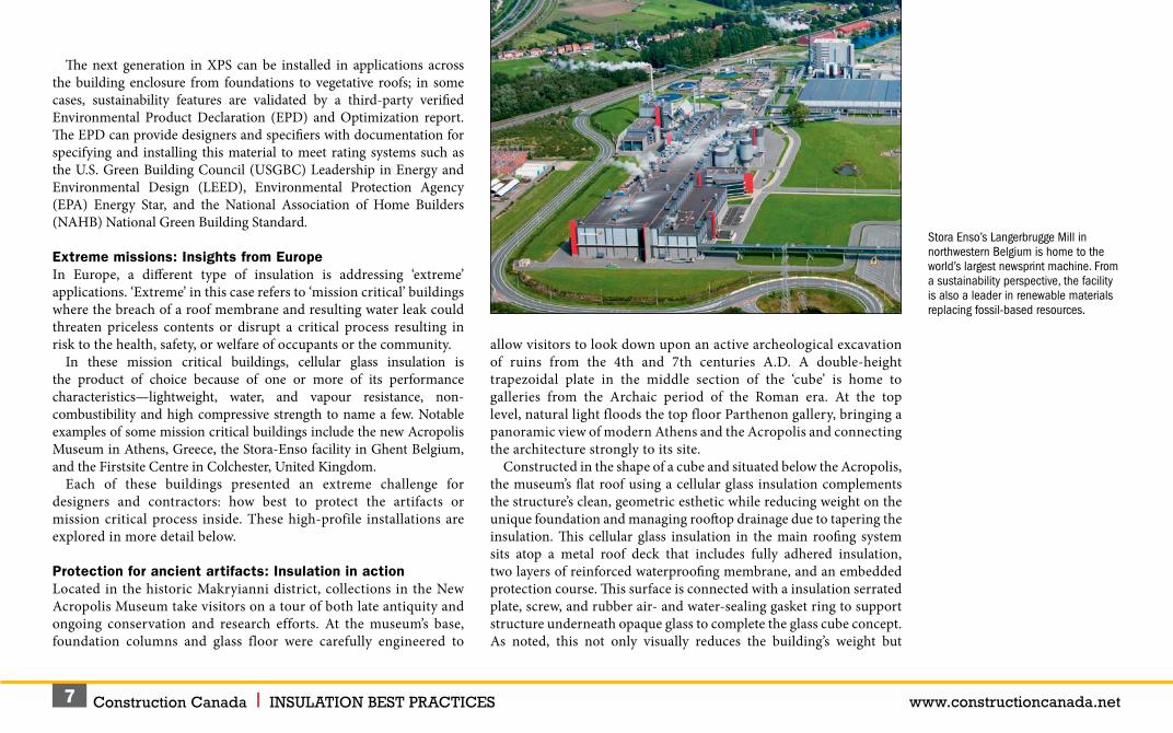
Stora Enso’s Langerbrugge Mill in northwestern Belgium is home to the world’s largest newsprint machine. From a sustainability perspective, the facility is also a leader in renewable materials replacing fossil-based resources.
allow visitors to look down upon an active archeological excavation of ruins from the 4th and 7th centuries A.D. A double-height trapezoidal plate in the middle section of the ‘cube’ is home to galleries from the Archaic period of the Roman era. At the top level, natural light floods the top floor Parthenon gallery, bringing a panoramic view of modern Athens and the Acropolis and connecting the architecture strongly to its site.
Constructed in the shape of a cube and situated below the Acropolis, the museum’s flat roof using a cellular glass insulation complements the structure’s clean, geometric esthetic while reducing weight on the unique foundation and managing rooftop drainage due to tapering the insulation. This cellular glass insulation in the main roofing system sits atop a metal roof deck that includes fully adhered insulation, two layers of reinforced waterproofing membrane, and an embedded protection course. This surface is connected with a insulation serrated plate, screw, and rubber air- and water-sealing gasket ring to support structure underneath opaque glass to complete the glass cube concept. As noted, this not only visually reduces the building’s weight but
Construction Canada l INSULATION BEST PRACTICES www.constructioncanada.net8
New ASTM Standard for Cellular Glass Insulation
When specifying cellular glass for roof and building applications, it is important to note new developments in standardization. On November 1, 2020, the American Society of Testing and
Materials (ASTM) created ASTM C1902, Standard Specification for Cellular Glass Insulation Used in Building and Roof Applications.* This standard specifically addresses physical and performance properties necessary for building applications, as opposed to the previously referenced ASTM C552, Standard Specification for Cellular Glass Thermal Insulation, which primarily applied to pipe and industrial insulation applications. As ASTM C552 is currently referenced as the product standard in the International Building Code (IBC) Section 1508 ‘Roofing Insulation, ASTM C1902, Standard Specification for Cellular Glass Insulation Used in Building and Roof Applications, is being proposed as a more direct replacement to address relevant properties such as compressive strength, thermal performance, moisture resistance, and dimensional stability under more applicable service temperatures ranging from 10 to 93 C (-50 to 200 F).** Specifiers will notice the same process of classifying materials by their physical properties in this standard—they are just more relevant to building construction needs. In the interim, specifiers should consider introducing this standard into future project manuals and local code officials have supported the use of the new standard for classifying cellular glass on projects.
*Visit www.astm.org/Standards/C1902.htm.** See www.astm.org/Standards/C552.htm.
provides less structural weight to the building without compromising thermal protection of the roof and adding to the critical mission of protecting artifacts from potential water infiltration. Ease of handling was a bonus during construction, as the cellular glass could be tapered during manufacture and easily cut in the field to accommodate lightening protection and variations in construction tolerance.
An extreme enclosure and roof evoke a ‘sheathed in gold’ effect ‘Extreme’ is an apt metaphor for the FirstSite Centre. The golden-clad crescent is a work of art embracing its historic surroundings of heritage gardens and sites as well as housing historic artifacts within. Ensuring developers did not disrupt historic sites did not compromise the mission to provide educational opportunities while actively commissioning and exhibiting artists of the present and future to form Colchester’s ‘future heritage.’ Connecting the public to art, the centre includes gallery spaces for hosting workshops, lectures, exhibits, and events. Yet another facility built atop a historic artifact, the Berryfield mosaic, dating back to 200 A.D. and discovered in 1923, is protected under a glass case built into the floor. As a result, the foundation was engineered as a concrete ‘raft’ due to a ‘no dig’ policy.
In this roof assembly, the cellular glass insulation was adhered to the structural deck with cold adhesive. Square plates were then embedded into the insulation and covered with the torch-applied roof membrane. Additional metal grips were screwed through this plate to create the attachment skeleton for the standing seam gold sheets (a copper and aluminum alloy). In a traditional architectural metal roof, these fasteners would have penetrated the roof membrane and the insulation to attach to the structure below. However, the method used here eliminates through-fasteners and, therefore, thermal bridging. The waterproof, dimensionally stable and high-compressive properties of the cellular glass also help hold the fasteners through the membrane securely and add a layer of waterproof material. This unique solution creates both a visually appealing extreme roof and protects valuable building contents.
Extreme processes define industrial operationsBeyond ancient artifacts and treasures, mission critical buildings housing industrial assets also protect extreme processes. A good example is Stora Enso’s Langerbrugge Mill in northwestern Belgium. The facility is home to the world’s largest newsprint machine. From a sustainability perspective, the facility is also a leader in renewable materials replacing fossil-based resources. In 2019, the company announced a pilot facility for enabling the production of bio-based plastics and found a way to recycle used paper cups to cut the carbon footprint of disposable paper cups by 50 per cent.
Once again, cellular glass plays a role in topping off this treasure. A cellular glass roof tops the 22,000 m2 (236,806 sf) area of flat roofs at the

Construction Canada l INSULATION BEST PRACTICES www.constructioncanada.net9
Langerbrugge Mill. The material composition aligns with the company’s investment in ecologically responsible activities. Totally inorganic, the cellular glass insulation used on this project does not contain any ozone-depleting propellants, flame retardants, or binders, and is free of volatile organic compounds (VOCs). Cellular glass is aligned with these company goals as it is a product with up to 60 per cent recycled content.
Industrial applications require massive strength on the roof as mechanical systems, heavy equipment, and even maintenance vehicles are often placed atop the structure. The Langerbrugge Mill’s rooftop supports mechanical and electrical equipment, requiring extreme loadbearing capacity. The compressive strength of cellular glass insulation begins at 345 kPa (50 psi) and is regularly used in building applications reaching 1655 kPa (240 psi). Dimensional stability and resistance to deflection is another consideration. The predominantly glass composition of cellular glass provides a low coefficient of thermal movement that is comparable to the movement of the concrete or steel decks to which it typically attaches. This quality means warping, dishing, or shrinking of the insulation does not occur. Cellular glass provides a stable foundation for the roofing membrane minimizing the stress placed on its joints and thereby prolonging the life of the roof.
Of particular concern in industrial applications, cellular glass is preferred where flammable liquids are used. Cellular glass is not a fuel source as it is non-combustible. It is classified as a Class A material per ASTM E84, Standard Test Method for Surface Burning Characteristics of Building Materials, due to zero flame spread and zero smoke development in independent third-party testing.4 This serves as an added benefit in critical facilities where threat of fire is increased and shutdown due to fire would result in significant loss.
One of the key reasons cellular glass was ideal for the Langerbrugge Mill was its vapour impermeable property. The printing process creates a significant vapour pressure that must be countered to protect the membrane and other roof components. Cellular glass has a maximum vapour permeability of 0.005 perms per inch Class I vapour retarder per ASHRAE 90.1 (per ASTM E96 Standard Test Methods for Water Vapour
Transmission of Materials Method B) compared to a range of 0.1 to 10 for similar rigid board insulation products (Class II or Class III). Limiting vapour transmission is also especially important in applications where the vapour is a chemical. Cellular glass is also acid- and chemically resistant, making it ideal for this and other pipe insulation applications.
Extreme functions critical to infrastructureBack in the United States, these physical properties were put to good use in extreme climates and roof applications. The Jardin Water Treatment Plant in Chicago, Illinois, can treat 3,785,412 L (1 million gal) of water a minute to serve Chicago and the surrounding area.5 The health of this community relies on this building to remain functioning, and downtime is simply not an option, even in humid summer highs or freezing winter lows. While the cellular glass serves as a redundant layer to prevent roof leaks, treatment of drinking water with chlorine and other chemicals to disinfect and remove contaminants also necessitates an insulation resistant to chemical exposure.6 Cellular glass uniquely solves this extreme problem.
In the Makryianni district of Greece, collections in the New Acropolis Museum take visitors on a tour of late antiquity and ongoing conservation and research. At the museum’s base, foundation columns and glass floor were carefully engineered to allow visitors to look down upon an active archeological excavation of ruins from the 4th and 7th centuries A.D.

Construction Canada l INSULATION BEST PRACTICES www.constructioncanada.net10
Over 50 years ago, cellular glass insulation was embedded as part of the roof membrane system. In 2009, as the roof membrane assembly was reaching the end of its expected lifespan, the insulation samples were removed from this roof and tested by an independent third party for its performance after so many years in service. Some of these results included no sign of freeze-thaw erosion, thermal performance as claimed, and negligible moisture content. After this proven performance, the same insulation was selected for installation on the Eugene Sawyer Facility, Chicago’s other mission-critical water treatment plant.
Conclusion In Europe, United States, and around the globe, designers must consider many extremes when it comes to the roof. The compliance standards are also rising, and safety is non-negotiable while improving impact on the planet. Innovations to familiar materials such as XPS are supporting growing sustainability efforts. Meanwhile, designers are innovating roof assemblies using time-tested cellular glass to meet extreme roof performance requirements.
Materials may be considered for their ability to create better roof drainage or even retain more moisture on a roof to relieve increased pressure on storm sewers. They may require a material to provide high compressive strength to accommodate fasteners and traffic. Or they may need extreme resistance to moisture and chemicals to support an entire community with vital services. Regardless of ‘extreme’ demands, these materials can reach new standards without compromise.
Notes1 Visit www.constructionspecifier.com/xps-building-science-three-high-performing-roofs.2 See static1.squarespace.com/static/58e3eecf2994ca997dd56381/t/5d84dfc371cf0822bdf7dc29/1568989140101/Green_Roof_and_Wall_Policy_in_North_America.pdf.3 Go to www.owenscorning.com/en-us/insulation/commercial/foamular-ngx to see a real-time map detailing states’ adoption of the regulations is available.
4 Consult www.astm.org/Standards/E84.htm.5 Read more at www.chicago.gov/city/en/depts/water/supp_info/education.html.6 Visit www.chicago.gov/city/en/depts/water/supp_info/education/water_treatment.html.
Historic wildfires in the West, tropical storms in the South, derechos in the Midwest, and an infusion of artic air devastating parts of Texas are just some of the recent climate events underscoring the need for commercial roofs to be able to withstand extreme moisture, wind, and thermal conditions.
Phot
os c
ourte
sy iS
tock
.com
/Sla
vica
Tiffany Coppock, AIA, NCARB, CSI, CDT, LEED AP, ASTM, RCI, EDAC is the Commercial Building Systems Specialist at Owens Corning. Tiffany resides in the Dallas Fort Worth area.

OVER 80 YEARS OF INNOVATION
1960Owens Corning Edmonton plant started producing Fiberglass insulation.
1978In September 1978, Owens Corning opens its ISB Toronto Plant and begins production of R20 23”. Earl Mogk is the Toronto Plant Leader.
1979Owens Corning starts packaging batt insulation in pink bags.
1980PINK PANTHER® rights from MGM worldwide in the building industry. The iconic MGM character and company “spokescat” has grown to become one of the world’s most recognizable and beloved brand mascots. Owens Corning began partnering with The Pink Panther to promote sales of PINK® Fiberglas® insulation on August 15, 1980.
1981Superpink II is introduced, the plant reaches 240 days without a lost time accident and the second Nodulator is installed. The Canada-arm is deployed aboard the Space Shuttle Columbia for the first time.
1989Owens Corning becomes the sole owner of Fiberglas® Canada. Canada eliminates one-dollar bills and switches to the “Loonie”.
1992Toronto plant started producing R19 and R30 for the U.S. Roberta Bondar became Canada’s first female astronaut in space. And the Toronto Blue Jays become the first Canadian baseball team to win the World Series.
1938Owens Corning invents fiberglass insulation.FIBERGLAS®
1987First company to register a colour in the world PINK®. After demonstrating decades of widespread use of the colour PINK®, Owens Corning became the first company to receive a trademark for a colour, on May 12, 1987.
PINK®
Owen's Corning_3_FP.indd 1Owen's Corning_3_FP.indd 1 8/24/21 10:52 AM8/24/21 10:52 AM

THE PINK PANTHER™ & © 1964-2021 Metro-Goldwyn-Mayer Studios Inc. All Rights Reserved. The colour PINK is a registered trademark of Owens Corning. © 2021 Owens Corning. All Rights Reserved. *73% recycled content is based on the average recycled glass content in all Owens Corning fiberglass batts, rolls and unbonded loosefill insulation manufactured in Canada. SCS certified.
OVER 80 YEARS OF INNOVATION
1995Fiberglas Canada officially becomes Owens Corning Canada. The Pink Panther becomes the new mascot.
1996Toronto plant employees participated in first Earth Day, the maple tree becomes Canada’s national arboreal emblem.
2002The Toronto plant diverts 61% of its waste from landfills. Canada signs the Kyoto Accord, limiting greenhouse gas emissions.
200776 per cent of ISB Toronto plant’s waste is diverted from landfills.
2008Owens Corning conquers the South Pole.
2011Owens Corning launches EcoTouch® PINK® FIBERGLAS® Insulation with PureFiber™ the new benchmark for insulation performance. The result is an entirely new class of high-performance, formaldehyde-free residential and commercial insulation containing 73%* recycled content.
2021Owens Corning launches PINK NEXT GEN™ FIBERGLAS® Insulation It’s not just the next generation of PINK® insulation – it’s the new standard. And the right choice for safety, precision, comfort and sustainability.
2021In January, Owens Corning (NYSE: OC) today announced a new product line: FOAMULAR® NGX (Next Generation Extruded). The proprietary blowing agent in this new line of extruded polystyrene (XPS) foam products delivers a 90% reduction in global warming potential (GWP) without sacrificing product performance.
1994Received certificate of appreciation from Mayor and Council of Scarborough for development of significant environmental initiatives.
2009Canada wins its fifth straight gold medal at the world junior hockey championship, defeating Sweden 5-1.

Construction Canada l INSULATION BEST PRACTICES www.constructioncanada.net13
Today’s high-performance building market is driven by increasingly stringent energy codes and a growing demand for greater building efficiency, sustainability, and affordability. This means specifying and building masonry cavity walls and adhered masonry walls with materials working together as a functioning system is more
critical than ever. When designing a highly functional masonry wall, the list of wall system performance criteria an architect must consider is daunting.
The wall must provide thermal efficiency, often with several types of insulation. In addition, it must offer air resistance while also managing moisture with properly designed and placed water-resistive barriers (WRBs). Further, the assembly must resist water leakage. However, when water does get in, it must be able to drain out of the cavity or from behind the adhered masonry veneer.
Due to their porous nature, masonry cavity walls are considered ‘rainscreen walls,’ and are expected to allow water into the cavity. Therefore, they must be designed to allow drainage and drying. Modern building science has shown high-quality adhered masonry walls such as stucco, stone, and thin brick also need to include drainage. The wall should resist vapour permeation, but when vapour penetrates, it must be able to dry, even when wetting and drying conflict with each other.
Structural connections are required to securely hold the entire system together, and at least three different modes of fire resistance should be considered, with multiple product warranties managed with these modes. Architects must provide the contractor with a complete list of material and system specifications to ensure the project can be bid accurately.
By Herbert Slone, RA, and Art FoxAll images courtesy Mortar Net Solutions
Best Practices forMasonry Wall Systems and Insulation
Construction Canada l INSULATION BEST PRACTICES www.constructioncanada.net14
Contractors need to build with familiar, proven methods and readily available materials, and they should have complete installation knowledge of every component. When the project is complete, they must provide job closeout information such as credits earned under the Leadership in Energy and Environmental Design (LEED) program and warranty documents.
Sometimes, the architect specifies everything the right way and the contractor installs components the right way, but problems still wreak havoc or the finished building. This is not because the building materials were of poor quality or the contractor was incompetent, but because some products just simply do not work together. For example, if a thermoplastic polyolefin (TPO) flashing membrane is sealed with a polyether sealant—both of which are tried-and-true, high-performance materials—the seal fails almost immediately. In order for the contractor to provide the best-quality construction, the architect must specify materials that have been tested and verified to be fully compatible and ensure plans are accurately detailed.
Architects can speed the design process, reduce risk, and help the contractor produce the best possible building by using complete wall assemblies consisting of components designed and documented to work together as a code-compliant system with full compatibility. These assemblies should also come with sequencing instructions making it clear how each component should be installed.
A complete wall systemA complete wall system has five functional layers. Two of the layers are the wall boundaries—the structural backup (e.g. steel or wood studs) and sheathing or concrete masonry units (CMU), and a weather-resistant cladding such as masonry on the exterior. Between these two boundaries are three functional layers containing all of the wall’s core components. A truly complete system provides the testing and documentation showing all the components performing as a system. The three functional layers are:• thermal efficiency;• air/water management; and• structural connections.They comprise components providing all of the necessary performance attributes relevant for a high-quality, sustainable wall. In stud walls, the
thermal efficiency components include stud cavity insulation, continuous insulation (ci), and a vapour retarder, if needed. In CMU walls, the block cells may be insulated. Insulation may also be installed on the interior, or the designer may rely on ci on the exterior of the block to meet requirements.
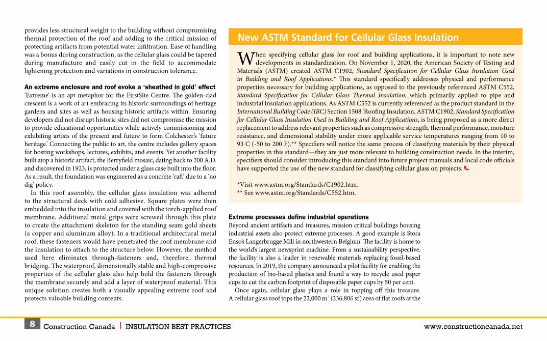
Air/water management encompasses multiple drainage planes, including air barriers and WRBs in cavity and adhered masonry walls, plus through-wall flashing in cavity walls. Sealing against air and water intrusion also requires the specification of mechanical fasteners with sealing washers. In cavity walls, weep vents and mortar dropping protection must be included. In adhered masonry walls, a drainage plane and weep screed must be specified, all without missing a detail.
Structural connections must be accomplished with single-barrel masonry anchors and sealing washers to properly transfer loads while minimizing and sealing necessary penetrations. Mineral wool safing insulation may also be required for fire protection.
An integrated, factory-assembled flashing system.

Construction Canada l INSULATION BEST PRACTICES www.constructioncanada.net15
Air barriersAir barriers restrict airflow in and out of the wall as well as minimize energy loss and condensation from moist leaking air. By controlling moisture, they reduce or prevent mould growth and corrosion while improving the building life and energy efficiency, as well as the overall comfort of occupants.
Some air barriers act as WRBs as well, providing a water-resistant envelope and thereby not only preventing water accumulation in the building, but also establishing a drainage plane inside the wall. The specifying architect must decide whether the WRB is sheet- or fluid-applied, rolled on, or sprayed, and whether it is permeable or impermeable. Among the popular choices are acrylic air- and water-resistive barriers, which are very flexible and have the ability to tolerate building movement. They are fluid-applied and permeable, so they permit limited vapour to pass through, which allows drying and provides ‘forgiveness’ against moisture accumulation in the wall—all while keeping liquid water out.
InsulationIn masonry veneer walls with wood or steel stud structural backup, batt insulation is normally specified in the stud cavity. However, since the stud framing creates a ‘thermal short’ through the cavity insulation layer—as much as 50 per cent through steel studs—the batt insulation value is often effectively cut in half. Therefore, ci is routinely added to the cavity in cavity walls and behind the lath in adhered masonry walls to conform to energy codes such as ANSI/American Society of Heating, Refrigerating and Air-conditioning Engineers/Illuminating Engineering Society (ASHRAE/IES) 90.1-2016, Energy Standard for Buildings Except Low-rise Residential Buildings. When properly installed using thermal break fasteners, ci minimizes thermal bridging so heat transfer is dramatically reduced.
Water inevitably gets into the air space in cavity walls and behind the lath in adhered masonry walls. Therefore, ci in the cavity or behind the lath should be highly water-resistant. In Tech Note 28-B, Brick Veneer/Steel Stud Walls, the Brick Industry Association (BIA) recommends the use of water-resistant, closed-cell, rigid foam insulation sheathing such as extruded polystyrene (XPS) to prevent water penetration. The chemistry and manufacturing
process of XPS causes it to be inherently water-resistant, meaning it does not rely on facers for this purpose. Facers are easily damaged onsite so they cannot be relied on to keep water out.
Sprayed polyurethane foam (SPF) is sometimes used in stud cavities or as ci. Sprayfoam has the advantage of being able to seal small cracks to limit air movement, but it requires careful control of in-field installation conditions to achieve the necessary insulating properties. Additionally, the application temperature, nozzle pressure, and speed of the applicator wand must be precise, and the installer must be very careful to use proper personal protection and overspray control.
When considering other insulation materials, water penetration, impact on thermal properties, fire resistance, and effects of site conditions on the performance of the product should be examined. XPS is a factory-made board product, meaning its insulating properties are quality controlled in the factory and proper installation is not as dependent on site conditions as sprayfoam.
The architect must also consider the installation method for ci. With board products, corrosion-resistant, ceramic-coated screws with air and
These mesh pieces are compressible and expandable weep opening devices with the ability to completely fill weep holes in wall systems.
Construction Canada l INSULATION BEST PRACTICES www.constructioncanada.net16
moisture, compared to cool air holding less moisture. In northern climates, the vapour retarder typically goes on the ‘warm-in-winter’ side or inside, while in the south, it goes on the outside.
Current practice utilizes modelling software such as WUFI to make detailed hourly simulations of moisture migration and accumulation over multiple annual cycles to assess designs and predict performance. All building materials, such as gypsum board or brick, absorb water, hold it, and then release it as conditions change. WUFI analysis takes those dynamic characteristics into consideration. Section 1405.3, “Vapour Retarders,” of the International Building Code (IBC) provides guidance on the use of vapour retarders in different climate zones.
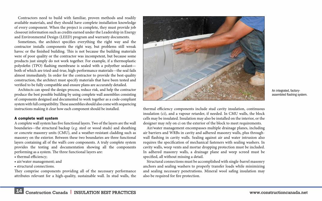
Air and weather barriers being installed on a façade comprised of concrete masonry units (CMUs).
water sealing washers offer long life and limit air movement and energy loss. Sealing washers are available with prongs that insert into the foam to enable the contractor to be more efficient by pre-spotting washer locations. The washers must be large enough to distribute the stress of pulling the water-resistant XPS insulation tight against the air barrier/sheathing to effectively seal the screw penetrations. Small details like this can make a big difference in how the wall assembly performs and should be part of the specification.
Moisture vapour retardersPlacement of a vapour retarder depends on several factors. Vapour generally flows from high to low pressure—high pressure being warm air holding more
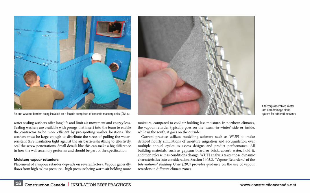
A factory-assembled metal lath and drainage plane system for adhered masonry.

Construction Canada l INSULATION BEST PRACTICES www.constructioncanada.net17
or down the face of the insulation to the bottom of the cavity, where it is directed across the shelf angle or foundation out of the wall by through-wall flashing.
Traditionally, masonry cavity walls have often employed field-assembled through-wall flashing. However, a newer, field-proven alternative is an integrated flashing system, which comes preassembled with all necessary components, including the membrane, termination bar, drip edge, and a drainage mat with weep tabs—a component often omitted entirely when field-assembled. One-piece, 355-mm (14-in.) high corners and end dams are also available to complete the system. With field assembly, all these components must be provided at the same time by different suppliers, and it takes experienced professionals to assemble the flashing system correctly.
Since flashing failure is one of the primary causes of water damage, it is vital these components be installed correctly in every detail throughout the building. However, with current labour shortages, finding installers with enough experience
When vapour-retarding facers are part of the stud cavity insulation, its flame spread rating must also be considered. In Type 1 and 2 construction, facer flame spread must be less than 25. In Type 3, 4, or 5 construction, facer flame spread may be above 25.
DrainageWater gets into a cavity wall through the brick veneer, which is normal and expected. Getting water out of a cavity wall involves the installation of multiple drainage planes, requiring numerous products including mortar dropping protection, through-wall flashing, and weep vents. Water also penetrates adhered masonry walls, and their proper design requires a WRB, drainage plane, and weep screed.
A complete wall design provides multiple pathways for drainage, does not allow the water to build up in the wall, and enables air to circulate to enhance drying. A reliable, high-performance wall system also has redundancies built in so if one aspect of the wall is challenged, there is another to back it up.
To keep weep holes open, mortar-dropping protection must be installed. With some proprietary three-dimensional, trapezoid-shaped porous fibre matrixes, falling mortar is suspended at different levels above the flashing, making it nearly impossible to accumulate a complete drainage block and thus keeping the weep holes open.
Weep holes used to be simply an open head joint at the base of the wall, but they allow a path for insects and debris to get in. Rope wicks allow water to leave the cavity, but they do not let air circulate. Rigid inserts preserve the opening and let water out and air in, but they may not fit the joint tightly or protect the opening well.
Some weep opening devices are both compressible and expandable, so they compress into the head joint and expand to fill irregularities. This type of a weep vent is a simple mesh tight enough to prevent insects and debris from getting in, but open enough to let water drain and air circulate.
Flashing systemsIn cavity walls, through-wall flashing is installed at the bottom of the wall to catch water and direct it out. Water drains down the air barrier/WRB layer behind the ci
A factory-assembled mesh drainage plane and metal lath system offers faster installation and fewer wall penetrations than when installing the drainage plane and lath separately.

Construction Canada l INSULATION BEST PRACTICES www.constructioncanada.net18
may be a problem. Factory assembly of the flashing system in controlled conditions eliminates most of the variability of field installation and allows less experienced professionals to create leak-free installations. Takeoff services and custom cutting for wall openings can also be used to speed installation.
In adhered masonry walls, a through-wall flashing is unnecessary. Instead, a weep screed is installed at the bottom of the wall, a minimum of 101 mm (4 in.) above grade (Uniform Building Code [UBC] Section 4706 [e], “Exterior Lath: Application of Metal Plaster Bases”). The WRB is installed shingle-fashion so it drapes over the screed flange to allow water to run down the barrier and out of the screed weep holes. A drainage plane between the lath and WRB is necessary to ensure moisture can run down the WRB and air can circulate behind the lath to dry the wall. Products combining a factory-assembled metal lath and drainage plane in one system can significantly cut installation time compared to installing the drainage plane and lath separately. They also provide a mortar break to prevent mortar bridging between the lath and WRB, so the wall can drain and dry quickly and completely.
Anchoring systemsFinally, anchoring devices must be specified to tie the masonry veneer to the structural backup. This is a critical component of a masonry wall’s stability and longevity, yet many designers frequently leave the choice of wall anchor to the contractors. These authors strongly recommend designers specify anchors with the same care they use on the rest of the wall.
In cavity walls, the anchors must be properly sized to span the cavity, as well as be corrosion-resistant. As cavities get larger to accommodate thicker ci, it becomes more important to properly engineer the anchors for shear strength. Stress-distributing air/water sealing washers are important to allow the anchors to be pulled tightly against the ci layer, which, as mentioned, effectively seals each anchor penetration against air and water leaks. For adhered masonry walls, nails or staples—typically used when lath is attached directly to the structural wall—may not be strong enough when using ci, and must also be properly engineered. With this masonry type, the fasteners support a large part of the veneer’s weight, so they must be able to resist both shear and pulling forces to function successfully.
Herbert Slone, RA, is Owens Corning’s chief architect and senior manager of commercial building systems. As a registered architect with more than 45 years of experience in construction, he provides leadership in building envelope systemization. Besides his role as an architect, he has also worked as a building official and university
instructor, authored articles, and chaired industry committees, and was appointed by Ohio’s Governor to the Ohio Board of Building Standards. Slone can be reached at [email protected].
Art Fox is marketing and communications director for Mortar Net Solutions. He ran several construction companies in the 1970s before becoming Mortar Net’s first COO, and has been involved in helping grow the company since its founding. Fox has also taught business writing and communications at Depaul University since
2003. He can be reached at [email protected].
ConclusionEconomic pressures, a strong desire for improved sustainability, and increasingly stringent energy requirements are forcing designers to find new ways to improve wall performance while making the architect and contractor’s jobs faster and less risky. The labour shortage is also driving the industry to find more efficient building techniques to meet growing commercial construction demand.
Specifying and installing pre-tested and warrantied complete wall systems addresses all these issues. These wall systems eliminate the need for designers to evaluate system testing and compatibility among multiple wall components. They slash design time, reduce designer and contractor risk, save contractors money by cutting installation time, and help stakeholders create beautiful, long-lasting, and sustainable buildings.

GREENGUARD Certified products are certified to GREENGUARD standards for low chemical emissions into indoor air during product usage. For more information, visit ul.com/gg. UL Environment claim validations lend third-party credibility to single-attribute environmental claims. *73% recycled content is based on the average recycled glass content in all Owens Corning fibreglass batts, rolls and unbonded loosefill insulation manufactured in Canada. THE PINK PANTHER™ & ©1964-2021 Metro-Goldwyn-Mayer Studios Inc. All Rights Reserved. The colour PINK is a registered trademark of Owens Corning. © 2021 Owens Corning. All Rights Reserved.
2
2
2
3
1
1
1
4
5
INTERIOR WALLS & ACOUSTICSQUIETZONE® PINK NEXT GEN™ FIBERGLAS® Acoustic InsulationOrThermafiber® SAFB™ Mineral Wool InsulationSelectSound® Black Acoustic Blanket or BoardQUIETZONE® Acoustic Floor Mat
EXTERIOR WALLSThermafiber® RainBarrier® ci HC 80/110/MaxFOAMULAR® NGX™ CodeBord®/C-200 Extruded Polystyrene Rigid InsulationPINK NEXT GEN™ FIBERGLAS® InsulationJointSealR™ Joint Seal Tape
UNDER SLABFOAMULAR® NGX™ 400/600/1000 High Density Extruded Polystyrene Rigid Insulation
ROOFINGFOAMULAR® NGX™ 350 Roof Insulation
PERIMETER FOUNDATION WALLSFOAMULAR® NGX™ C-300 Extruded Polystyrene Rigid Insulation
1
2
3
4
5
WESTERN CANADA Luis Faria, B.Eng, PMP, CMgr MCMI
Technical Sales Manager, Western Canada
QUEBEC & ATLANTIC CANADA Salvatore Ciarlo, P.Eng
Architectural Solutions & Technical Services Manager, [email protected]
1.800.504.8294
DELIVERING A DIFFERENCE
TOTALSHIELDCOMMERCIAL ENCLOSURE SYSTEM
™
Using Owens Corning® PINK NEXT GEN™ FIBERGLAS® Insulation, FOAMULAR® NGX™ Rigid Foam Insulation and Thermafiber®
Mineral Wool Insulation helps provide a durable, energy efficient building enclosure. Look to Owens Corning products for energy
efficient, acoustically sound and cost efficient solutions in institutional, commercial and industrial buildings.
To learn more contact our Owens Corning Building Science Experts at specowenscorning.ca/contacttech
20 | FOAMULAR® XPS Insulation
AVERAGE 73% RECYCLED CONTENT61% POST-CONSUMER12% PRE-CONSUMER
RECYCLED CONTENT
73 | PINK® FIBERGLAS® Insulation
Owen's Corning_4_FP.indd 1Owen's Corning_4_FP.indd 1 8/24/21 10:57 AM8/24/21 10:57 AM

Construction Canada l INSULATION BEST PRACTICES www.constructioncanada.net20
An accurate assessment of the watertightness of new and existing roofs can potentially save building owners hundreds of millions of dollars
annually. The challenge for roofing specifiers is choosing the most effective exterior-to-interior watertightness evaluation techniques.
The fact is there is no single, straightforward method to accurately evaluate water ingress from the exterior roof membrane to the interior of the building. This has led to confusion among specifiers as to which method is most appropriate for a particular type of roof, and what information each test provides.
This dilemma has led the Roofing Industry Committee on Weather Issues (RICOWI) to review existing water-detection techniques to identify:• methods of operation;• capabilities of the tests;• test compatibility with various
components; and• benefits and the shortcomings of each test
procedure.RICOWI’s Moisture Control and Green Committee led this investigation, as the group focuses on moisture-control issues and identifies specific roof performance
Identifying Watertightness of Low-slope Roof Membranes
By Dominique Lefebvre and Bas A. Baskaran, PhD, P.Eng.Photo courtesy GAF

Construction Canada l INSULATION BEST PRACTICES www.constructioncanada.net21
metrics. Committee membership consists of manufacturers, property owners, and academics to ensure a diverse roofing community representation.
Addressing watertightness of roofsThe main function of any roof is to prevent water entry into a building. This leads to the fundamental question of how to assess the watertightness of a roof assembly.
Watertightness detection is needed for both new and existing roof systems. For new construction, this watertightness evaluation provides confirmation to the property owner the roof was properly installed, and as such, can be used as a field commissioning tool.
For existing construction, a watertightness evaluation can be employed for the following two purposes:• to assess the current roof condition and determine if replacement is required
after confirmation from test cuts and professional insight; and• to evaluate if the watertightness capacity of a roof was compromised
after a major weather event.From the perspective of the roofing specifier and property owner, effective nondestructive roofing and waterproofing testing can provide various practical benefits. For example:• pinpointing, documenting, and repairing wet roof areas to limit further
damage to commercial low-slope roofs;• reducing the risk of structural damage and potential failure of new or
existing roof systems;• identifying sound roof sections and replacing wet insulation to conserve
time, materials, and energy use; and• targeting problem areas to accurately budget roof maintenance and
improve specifications for competitive bidding procedures.
Electronic leak detectionLow- and high-voltage electrical leak detection methods can be used to identify the source of a leak in a roof assembly. Both techniques use electrical conductance to test the integrity of roof membranes. They can detect a breach based on the flow of current to a conductive surface below the membrane.
Electronic leak detection requires three conditions for accurate testing, including:• grounding medium beneath the membrane to receive the electric current;• electrically nonconductive membrane; and• lack of electrically insulated materials between the membrane and the ground.The low-voltage method uses the presence of water to identify a membrane breach, whereas high-voltage is a ‘dry’ method. Both tests may be faster, safer, and more economical to specify than flood testing of the roofing system.
Moisture can be observed on the bottom of the membrane. There is rust accumulation on the fastener plate due to the presence of water.
Phot
o co
urte
sy N
atio
nal R
esea
rch
Coun
cil C
anad
a

Construction Canada l INSULATION BEST PRACTICES www.constructioncanada.net22
According to the National Roofing Contractors Association (NRCA), flood testing is a membrane-integrity test conducted by plugging or closing any drains and erecting temporary dams where required to retain water on the surface of a waterproofing membrane. The surface of the roof is then flooded to a maximum depth of 51 mm (2 in.) at its highest point. This water must be retained for a minimum of 24 hours or as long as required by the manufacturer.
NRCA does not recommend flood tests as part of a routine quality control/assurance (QC/A) program for a new roof system. One reason is flood tests are sometimes solely and incorrectly relied on to determine the quality of a roof system. Flood testing alone does not forecast a properly designed or installed roof system. For example, the test will not provide information about service life or evaluate a roof system’s ability to resist wind or impact loads.
Flood testing also is not appropriate for identifying potential leak sources. Roof systems are designed to be weatherproof and not waterproof. While a weatherproof roof resists the passage of water with a minimal amount of hydrostatic pressure (flowing water), waterproofing systems prevent the passage of water under hydrostatic pressure (standing water). For example, water leakage may occur at roof drain flashings with flood testing that exposes drains to hydrostatic pressure. It is important to note roof drains are not designed to be leak-free under such unrealistic imposed conditions.
When using the Low Voltage–Wet Method per ASTM D7877, Standard Guide for Electronic Methods for Detecting and Locating Leaks in Waterproof Membranes, a conductor cable loop is installed around the perimeter of the area to be tested. The cable loop is connected to a low-voltage pulsating
While roof-evaluation techniques require access to the entire roof surface, they can narrow down potential problems, such as the HVAC penetrations on this roof.
Phot
o ©
Big
Stoc
kPho
to.c
om
Low- and high voltage electronic leak detection methods use electrical conductance to test the integrity of roof membranes.
Phot
o co
urte
sy S
ika
Sarn
afil

Construction Canada l INSULATION BEST PRACTICES www.constructioncanada.net23
highly conductive materials such as steel or structural concrete deck. Low-voltage evaluation with existing black ethylene propylene diene monomer (EPDM) and butyl membranes or assemblies with aluminized protective coatings is ineffective due to the high electrical conductivity of these materials.
At the same time, roof coverboards will block the electrical field unless a conductive material (wire grid or primer) is placed directly under the membrane.
Not all roofing manufacturers have approved the installation of wire grid directly under the membranes. Additionally, when using conductive primers, some manufacturers have not performed compatibility testing with the membranes.
On roof systems where overburden has been installed, only low-voltage evaluations may be specified, as high-voltage testing requires direct contact with the membrane.
generator and the upper electrical plate is formed by dampening the area within the loop. By grounding the conductive deck, it acts as the lower electrical plate, and the roof membrane acts as the insulator. When a breach is present, current will flow through the opening of the membrane to the deck, completing the circuit.
The low-voltage method can identify the leak source. It cannot detect moisture accumulation in roof insulation or measure the moisture content in the roof system. Therefore, this technique is not applicable to roof systems containing insulation because it blocks the electrical field. Similarly, low-voltage detection is inappropriate for use in roof systems containing a vapour retarder that will mask the breach by blocking the electrical field.
This technique has historically been of greatest value when investigating protected membrane roof (PMR) assemblies or inverted roof membrane assemblies (IRMAs) or when the membrane is applied directly to
Imag
es c
ourte
sy IR
Ana
lyze
rs/V
ecto
r Map
ping
Infrared imaging is often used at night when the roof begins to cool because the wet insulation (higher mass) retains heat longer than the dry area (lower mass). The infrared camera is able to capture the temperature differential between the dry and wet roof areas as illustrated in these images.

Construction Canada l INSULATION BEST PRACTICES www.constructioncanada.net24
References
1. ASTM D7877, Standard Guide for Electronic Methods for Detecting and Locating Leaks in Waterproof Membranes.
2. ASTM D7954, Standard Practice for Moisture Surveying of Roofing and Waterproofing Systems Using Non-Destructive Electrical Impedance Scanners.
3. The paper “Climate Change Adaptation Technologies for Roofing” by B. Baskaran, S. Molleti, D. Lefebvre, and N. Holcroft for the 33rd RCI International Convention and Trade Show.
4. “Electronic Leak Detection: Sound Science, Not a Magic Wand” by P. Brooks in the July 2017 issue of RCI Interface.
5. Testing Application Standard (TAS) 126-95, Standard Procedures for Roof Moisture Surveys.6. “Electronic Leak Detection: A Quality Assurance Tool” by D. Honza for RCI Interface.7. Infrared Roof Moisture Surveys Accurate Assessment of Roof Condition. Visit www.iranalyzers.com/
infraredroof.htm for more information.8. Nuclear Roof Moisture Surveys. Retrieved from IR Analyzers Vector Mapping at www.iranalyzers.com/
nuclearroof.htm.9. “A Comparison of Three Different Technologies for Performing Nondestructive Roof
Moisture Survey” by J. Robinson, D. Bradford, J. Mitchell, and P. Majkowski, published in the Proceedings of the North American Conference on Roofing Technology.
10. The American National Standards Institute/Single Ply Roofing Industry (ANSI/SPRI)/RCI NT-1, Detection and Location of Latent Moisture in Building Roofing Systems by Nuclear Radioisotopic Thermalization.
Many factors can adversely influence the accuracy of low-voltage testing. For example, vegetative roofs and other assemblies with overburden are typically fitted with on-demand leak detection systems. Part of the process includes the installation of conductive wire loops on the surface of the membrane after the overburden is applied. Connection boxes are used above the overburden to provide access to the wiring at a later date. These existing electronic detection devices can interfere with low-voltage watertightness evaluations. Also, the membrane surface must be wet, which may create serious difficulties with some overburden systems.
When used under ideal conditions (i.e. highly conductive materials below the roof membrane), there is still the potential for false positives. The operator’s experience is important for interpreting results accurately. This is particularly true when low-voltage testing through overburden, where the
operator is required to interpret the relatively subtle patterns achieved with low levels of voltage.
When using the High Voltage–Dry Method per ASTM D7877, an electrical lead is connected to the roof deck, while another is attached to the device (resembling a push broom with copper bristles). The membrane acts as an insulator. When a breach is present in the membrane, the electricity will flow through the defect and ground to the conductive roof deck.
Drains provide good grounding components, as the drain lines are secured to the structure. However, those with polyvinyl chloride (PVC) piping are
Phot
o co
urte
sy G
AF
Readings cannot be obtained if water is present behind flashings or under the membrane from adjacent surfaces such as windows, storefronts, porous masonry, and unsealed base flashings.

Construction Canada l INSULATION BEST PRACTICES www.constructioncanada.net25
ineffective. Metal vent pipes, metal flashings, and exposed rebar secured to the structure are additional grounds.
Similar to the ‘wet’ method, this high-voltage technique can be used to identify the leak source, but cannot detect moisture accumulation in roof insulation or measure the moisture content present in the roof system.
For roof membranes other than black EPDM, the surface must be completely dry and exposed. If water is present behind flashings or under the membrane from adjacent surfaces (e.g. windows, storefronts, porous masonry, or unsealed base flashings), readings cannot be obtained, as breaches will not be detected.
Additionally, more false positive results have been reported using this method compared to low-voltage testing.1
Infrared thermographyThe infrared thermography method uses infrared imaging to identify temperature differentials between dry and wet locations to indicate the presence of water in the system. This method operates on the principle wet insulation has a higher thermal mass and, therefore, retains heat longer than dry insulation. Although this method is not time consuming and allows the operator to sample the entire roof, it can provide misleading information. Since the testing relies on differences in temperature, mechanical equipment, heating/cooling systems, and shaded areas can adversely influence the results.
Infrared imaging per ASTM C1153, Standard Practice for Location of Wet Insulation in Roofing Systems Using Infrared Imaging, and Testing Application Standard (TAS) 126-95, Standard Procedures for Roof Moisture Surveys, is used to determine the location of wet insulation in contact with the membrane in the roofing system. This test method is often used at night when the roof begins to cool because the wet insulation (higher mass) retains heat longer than the dry area (lower mass). The infrared camera is able to capture the temperature differential between the dry and wet roof areas.
Unlike electronic leak detection, infrared thermography is unable to identify the source of the leak. However, moisture content can be measured using core samples.
This photo shows water below the roof membrane.
Phot
o co
urte
sy N
atio
nal R
esea
rch
Coun
cil C
anad
a
Infrared thermography can be specified to analyze the presence of moisture in all types of roof membranes. However, it is incompatible with ballasted roof assemblies or PMR/IRMA varities. During testing, the membrane must be dry and devoid of condensation. This test method is not suitable on insulations that do not absorb water, such as expanded polystyrene (EPS) and closed-cell sprayed polyurethane foam (SPF). Additionally, infrared thermography should not be specified when the existing roof deck is capable of retaining significant amounts of water. These wet-applied decks include lightweight concrete and poured gypsum.
Similar to other methods of moisture detection, infrared thermography can generate false positives, and the operator’s experience is important for interpreting results accurately.

Construction Canada l INSULATION BEST PRACTICES www.constructioncanada.net26
Nuclear detection techniquesThe nuclear water detection method employs radioisotopic thermalization to emit high-velocity neutrons and measure backscatter. Although this method is directly detecting the presence of hydrogen, and therefore water, in the roof assembly, it requires operation by licensed personnel due to its complexity (e.g. unit angle sensitivity and baseline reading requirements).
Radioisotopic thermalization (TAS 126-95 and American National Standards Institute/Single Ply Roofing Industry [ANSI/SPRI]/RCI NT-1-2017, Detection And Location Of Latent Moisture in Building Roofing Systems by Nuclear Radioisotopic Thermalization) involves a process where a nuclear moisture meter emits high-velocity neutrons and measures backscattered ‘slow’ neutrons that have lost much of their energy in collisions with hydrogen atoms. Thus, higher levels of slowed neutrons are recorded at wet areas, as water contains a significant amount of hydrogen atoms.
Nuclear leak detection is also able to identify the accumulation of moisture in insulation, but cannot pinpoint the source of the leak(s). Core samples may be taken of dry and wet locations to determine moisture content.
This technique is applicable to all conventional roof assemblies except metal roofs. Nonconventional PMR (upside down) roofs are incompatible with nuclear watertightness evaluations. Roofs with overburden may be tested only if the ballast or pavers are removed from the test area. In most cases, the practicality of using this time-consuming method of watertightness detection beneath vegetative roof assemblies would be of questionable value to specifiers.
As with other methods of watertightness detection outlined here, there is the potential for false positives.
Typically, a baseline reading to calibrate the nuclear meter must be taken in a known dry area of the roof. The nuclear meter samples about 0.6 m2 (6.5 sf) at each grid point in a 0.9 x 0.9-m (3 x 3-ft), 1.8 x 1.8-m (6 x 6-ft), or 3 x 3-m (10 x 10-ft) pattern. The equipment has a depth limitation of 1.8 to 2.4 m (6 to 8 ft). However, unlike several other methods of watertightness evaluation that are employed, nuclear scanning is not dependent on climatic conditions.
Increasing Resiliency of Roofing Systems
The federal government has initiated a mandate to increase the resiliency of the built environment through the Climate Resilient Buildings and Core Public Infrastructure project at the National
Research Council Canada (NRC). The initiative includes two major projects relevant to the roofing industry.
The Guidelines for Commissioning and Certifying the Resiliency of Roofs Subjected to Extreme Weather Events project involves developing field protocols to perform in-situ assessments of wind uplift resistance, watertightness, and thermal performance. These tools will allow the industry to assess the capacity of a new roof, ensuring it was installed to meet the design requirements and withstand climatic events. The guidelines will also provide the industry with a method of assessing the remaining roof capacity after either an extreme event or field aging.
The Codification of Material Properties for Building Adaptation to Climate Change project includes evaluation of the properties of more than 20 common building materials for various climatic zones to develop a database of climate-dependent material properties. One of the major outcomes of this initiative is the development of an online database tool to improve access and ease of use for the building envelope community.
Both NRC projects are aimed at increasing the resilience of the building envelope and roofing. These initiatives were identified through an industry consultation on building resiliency held in 2016. The methodologies derived from the climate adaptation projects are scheduled for inclusion in the National Building Code of Canada (NBC).
It is important to note areas of ponding water on the roof surface will result in increased readings from the nuclear meter. Readings can also be affected by inconsistencies seen among roofing components, such as joints where the different elements meet one another.

Construction Canada l INSULATION BEST PRACTICES www.constructioncanada.net27
Further, technicians may need to comply with Canadian Nuclear Safety Commission (CNSC) regulations.
Electrical impedance evaluationsThe electrical impedance method uses a device to create an alternating electrical field for penetrating the roofing material. Since wet insulation provides less resistance to electrical current than dry, the current can be correlated to the presence of water. The alternating current flowing through the field is inversely proportional to the impedance of the moisture-absorbing materials. On the downside, the electrical impedance unit contains a scanner sensitive to interply and surface moisture and inconsistencies in the roof system.
Like the nuclear method, this technique is applicable to most conventional roof assemblies except for black EPDM membranes or assemblies treated with aluminized protective coatings. PMR roofs are incompatible with electrical impedance watertightness evaluations, and any roofs with overburden may be tested only if the ballast or pavers are removed from the test area. It is critical for the membrane to be free of surface moisture to obtain accurate readings.
Similar to the nuclear and infrared methods, the impedance method is also able to identify moisture accumulation in insulation, but cannot pinpoint the source of the leak(s). Again, core samples may be taken of dry and wet locations to determine the moisture content.
As always, the operator’s experience is essential for interpreting results accurately. Other potential issues reducing instrument sensitivity include aggregate-ballasted and/or aggregate-surfaced membranes with variable size and weight. As mentioned, the scanners are also more sensitive to interply moisture and water closer to the scanner electrodes, which can make readings further below the membrane difficult. Roof patches dissimilar to the system under testing may also result in erroneous readings.
While the electrical impedance watertightness method is easy to use and less complex than other evaluation techniques, the presence of dew, rain, snow, and ice significantly affects the readings.
When using the High Voltage–Dry Method, one electrical lead is connected to the roof deck, while another is attached to the device (resembling a push broom with copper bristles). The membrane acts as an insulator.
Imag
es c
ourte
sy IR
Ana
lyze
rs/V
ecto
r Map
ping
The low-voltage method can identify the leak source. It cannot detect moisture accumulation in roof insulation or measure the moisture content present in the roof system.

Construction Canada l INSULATION BEST PRACTICES www.constructioncanada.net28
ConclusionNone of the moisture-detection methods described in this article are able to quantify the moisture content without performing core samples, which is undesirable due to the destructive nature of this sampling.
For all water-detection methods, there is the potential for false positive readings. The experience and/or licensing of the operator is essential for performing the test and interpreting the results accurately. All the methods investigated are also sensitive to the type of roof assembly under evaluation.
Based on the review conducted by RICOWI’s Moisture Control and Green Committee, it is evident a generic method does not exist to detect exterior water entry into all types of roof assemblies.
A common industry practice is to employ a combination of applicable methods to both detect the presence of water in a roof assembly and identify the source of the leak. Since infrared thermography is the most simple and convenient method, it is often used in conjunction with another, more technical method to detect the presence of water depending on the roof type.
It is important watertightness evaluations are not only specified in the aftermath of a major weather event or roof leak, but also included as part of a regular maintenance program.
Without performing regular watertightness evaluations, property owners will either be left guessing whether there is a problem with their roofs or will only be made aware of an issue once it has progressed to visible interior damage.
However, by combining water-detection methods suitable for a particular roof, one can obtain reliable information on the watertightness resistance and condition of an existing roof system.2
Notes1 For more information, read “Everything Leaks: Testing roofs to ensure watertightness at the outset” by Ronald J. Ray, RA, CCS, CCCA, CSI, AIA, in the February 2017 issue of The Construction Specifier. Visit www.constructionspecifier.com/everything-leaks-testing-roofs-to-ensure-watertightness-at-the-outset.
2 Special thanks to David Hawn of Dedicated Roof and Hydro-Solutions for his comments on this article. The authors acknowledge the members of the Moisture Control and Green Committee of the Roofing Industry Committee on Weather Issues (RICOWI) for their input, especially David Balistreri of Building Envelope Consultants, Greg Keeler of Owens Corning, Peter Brooks of IR Analyzers Vector Mapping, Shaun Katz of Detec, Tom Kelly of 2001 Company, and William Tipton of Roof Maintenance Systems.
Dominique Lefebvre is a research officer with the National Research Council Canada (NRC). Her research area focuses on the evaluation of the interface of various roofing materials, as well as the development of tools and techniques for climate adaptation of commercial roofs. Currently, she is working on developing the performance requirements of
coverboards in low-slope membrane roofing for the creation of a harmonized standard. Lefebvre can be reached via email by contacting at [email protected].
Bas A. Baskaran, PhD, P. Eng., is a group leader at NRC, where he researches the performance of roofing systems and insulation. He is an adjunct professor at the University of Ottawa, and a member of Roofing Committee on Weather Issues (RICOWI), RCI Inc., Single Ply Roofing Industry (SPRI), and several other technical committees. Baskaran is
a research advisor to various task groups of the National Building Code of Canada (NBC). He was recognized by Her Majesty Queen Elizabeth II with a Diamond Jubilee medal for his contribution to fellow Canadians. Baskaran can be reached at [email protected].