Brother 3550-4550-6550-7550-9000-9500 Service Manual
171
FACSIMILE EQUIPMENT SERVICE MANUAL MODEL: FAX3550/800P MFC4550/6550MC/7550MC MFC9000/9500 Enable Thumbnails Enable Book Marks Exit Acrobat Viewer
-
Upload
randyengesett2494 -
Category
Documents
-
view
116 -
download
1
Transcript of Brother 3550-4550-6550-7550-9000-9500 Service Manual

FACSIMILE EQUIPMENTSERVICE MANUAL
MODEL: FAX3550/800PMFC4550/6550MC/7550MCMFC9000/9500
Enable Thumbnails
Enable Book Marks
Exit Acrobat Viewer
FACSIMILE EQUIPMENT
SERVICE MANUAL
MODEL: FAX3550/8000PMFC4550MFC6550MC/7550MCMFC9000/9500

© Copyright Brother 1996
All rights reserved.
No part of this publication may be reproduced in anyform or by any means without permission in writingfrom the publisher.
Specifications are subject to change without notice.
PREFACE
This publication is a Service Manual covering the specifications, construction, theory of opera-tion, and maintenance of the Brother facsimile equipment. It includes information required forfield troubleshooting and repair—disassembly, reassembly, and adjustment—so that servicepersonnel will be able to understand equipment function, to rapidly repair the equipment andorder any necessary spare parts.
To perform appropriate maintenance so that the facsimile equipment is always in best conditionfor the customer, the service personnel must adequately understand and apply this manual.
This manual is made up of six chapters and appendices.
CHAPTER I. GENERAL DESCRIPTION
CHAPTER II . INSTALLATION
CHAPTER III . THEORY OF OPERATION
CHAPTER IV . DISASSEMBLY/REASSEMBLY AND LUBRICATION
CHAPTER V. MAINTENANCE MODE
CHAPTER VI . ERROR INDICATION AND TROUBLESHOOTING
APPENDICES Circuit Diagrams
This manual describes the model and its versions to be destined for major countries. The specificationsand functions are subject to change depending upon each destination.

SAFETY INFORMATION
Laser Safety (110 - 120V Model only)
This printer is certified as a Class 1 laser product under the US Department of Health and HumanServices (DHHS) Radiation Performance Standard according to the Radiation Control for Healthand Safety Act of 1968. This means that the printer does not produce hazardous laser radiation.
Since radiation emitted inside the printer is completely confined within the protective housings andexternal covers, the laser beam cannot escape from the machine during any phase of user opera-tion.
CDRH Regulations (110 - 120V Model only)
The Center for Device and Radiological Health (CDRH) of the US Food and Drug Administrationimplemented regulations for laser products on August 2, 1976. These regulations apply to laserproducts manufactured from August 1, 1976. Compliance is mandatory for products marketed in theUnited States. The label shown below indicates compliance with the CDRH regulations and must beattached to laser products marketed in the United States.
The label for Japanese products
MANUFACTURED: JUNE 1996 K
BROTHER INDUSTRIES, LTD.
15-1 Naeshiro-cho Mizuho-ku Nagoya 467, Japan.
This product complies with FDA radiation
performance standards, 21 CFR Subchapter J.

CHAPTER I.
GENERAL DESCRIPTION

CONTENTS
1. EQUIPMENT OUTLINE.................................................................................. I-1
1.1 External Appearance and Weight ........................................................... I-1
1.2 Components ........................................................................................... I-1
2. SPECIFICATIONS .......................................................................................... I-2
I – 1
1. EQUIPMENT OUTLINE
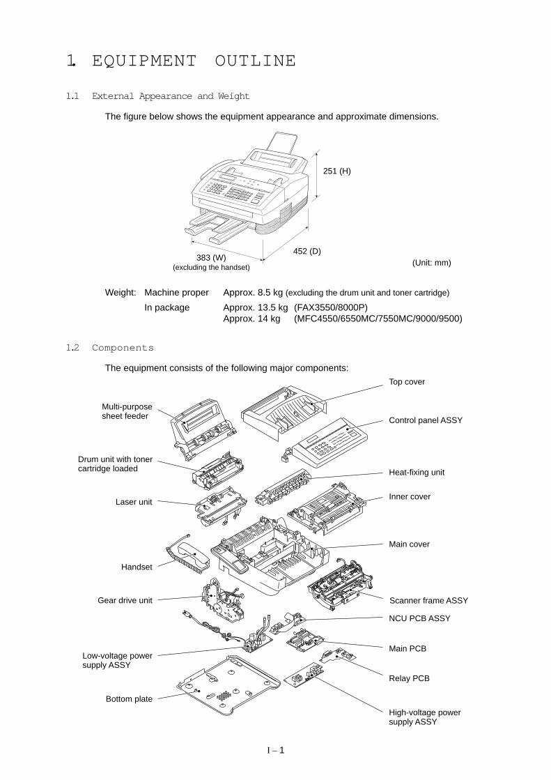
1.1 External Appearance and Weight
The figure below shows the equipment appearance and approximate dimensions.
251 (H)
452 (D)383 (W)
(excluding the handset)(Unit: mm)
Top cover
High-voltage powersupply ASSY
Relay PCB
Main PCB
NCU PCB ASSY
Scanner frame ASSY
Main cover
Control panel ASSY
Heat-fixing unit
Inner cover
Multi-purposesheet feeder
Drum unit with tonercartridge loaded
Laser unit
Handset
Gear drive unit
Low-voltage powersupply ASSY
Bottom plate
Weight: Machine proper Approx. 8.5 kg (excluding the drum unit and toner cartridge)
In package Approx. 13.5 kg (FAX3550/8000P)Approx. 14 kg (MFC4550/6550MC/7550MC/9000/9500)
1.2 Components
The equipment consists of the following major components:
I – 2
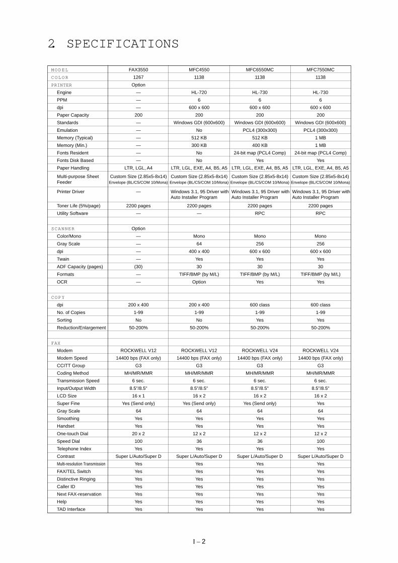
2. SPECIFICATIONS
M O D E L FAX3550 MFC4550 MFC6550MC MFC7550MC
C O L O R 1267 1138 1138 1138
PRINTER Option
Engine — HL-720 HL-730 HL-730
PPM — 6 6 6
dpi — 600 x 600 600 x 600 600 x 600
Paper Capacity 200 200 200 200
Standards — Windows GDI (600x600) Windows GDI (600x600) Windows GDI (600x600)
Emulation — No PCL4 (300x300) PCL4 (300x300)
Memory (Typical) — 512 KB 512 KB 1 MB
Memory (Min.) — 300 KB 400 KB 1 MB
Fonts Resident — No 24-bit map (PCL4 Comp) 24-bit map (PCL4 Comp)
Fonts Disk Based — No Yes Yes
Paper Handling LTR, LGL, A4 LTR, LGL, EXE, A4, B5, A5 LTR, LGL, EXE, A4, B5, A5 LTR, LGL, EXE, A4, B5, A5
Multi-purpose Sheet Custom Size (2.85x5-8x14) Custom Size (2.85x5-8x14) Custom Size (2.85x5-8x14) Custom Size (2.85x5-8x14)Feeder Envelope (BL/C5/COM 10/Mona) Envelope (BL/C5/COM 10/Mona) Envelope (BL/C5/COM 10/Mona) Envelope (BL/C5/COM 10/Mona)
Printer Driver — Windows 3.1, 95 Driver with Windows 3.1, 95 Driver with Windows 3.1, 95 Driver withAuto Installer Program Auto Installer Program Auto Installer Program
Toner Life (5%/page) 2200 pages 2200 pages 2200 pages 2200 pages
Utility Software — — RPC RPC
SCANNER Option
Color/Mono — Mono Mono Mono
Gray Scale — 64 256 256
dpi — 400 x 400 600 x 600 600 x 600
Twain — Yes Yes Yes
ADF Capacity (pages) (30) 30 30 30
Formats — TIFF/BMP (by M/L) TIFF/BMP (by M/L) TIFF/BMP (by M/L)
OCR — Option Yes Yes
C O P Y
dpi 200 x 400 200 x 400 600 class 600 class
No. of Copies 1-99 1-99 1-99 1-99
Sorting No No Yes Yes
Reduction/Enlargement 50-200% 50-200% 50-200% 50-200%
FAX
Modem ROCKWELL V12 ROCKWELL V12 ROCKWELL V24 ROCKWELL V24
Modem Speed 14400 bps (FAX only) 14400 bps (FAX only) 14400 bps (FAX only) 14400 bps (FAX only)
CCITT Group G3 G3 G3 G3
Coding Method MH/MR/MMR MH/MR/MMR MH/MR/MMR MH/MR/MMR
Transmission Speed 6 sec. 6 sec. 6 sec. 6 sec.
Input/Output Width 8.5"/8.5" 8.5"/8.5" 8.5"/8.5" 8.5"/8.5"
LCD Size 16 x 1 16 x 2 16 x 2 16 x 2
Super Fine Yes (Send only) Yes (Send only) Yes (Send only) Yes
Gray Scale 64 64 64 64
Smoothing Yes Yes Yes Yes
Handset Yes Yes Yes Yes
One-touch Dial 20 x 2 12 x 2 12 x 2 12 x 2
Speed Dial 100 36 36 100
Telephone Index Yes Yes Yes Yes
Contrast Super L/Auto/Super D Super L/Auto/Super D Super L/Auto/Super D Super L/Auto/Super D
Multi-resolution Transmission Yes Yes Yes Yes
FAX/TEL Switch Yes Yes Yes Yes
Distinctive Ringing Yes Yes Yes Yes
Caller ID Yes Yes Yes Yes
Next FAX-reservation Yes Yes Yes Yes
Help Yes Yes Yes Yes
TAD Interface Yes Yes Yes Yes
I – 3
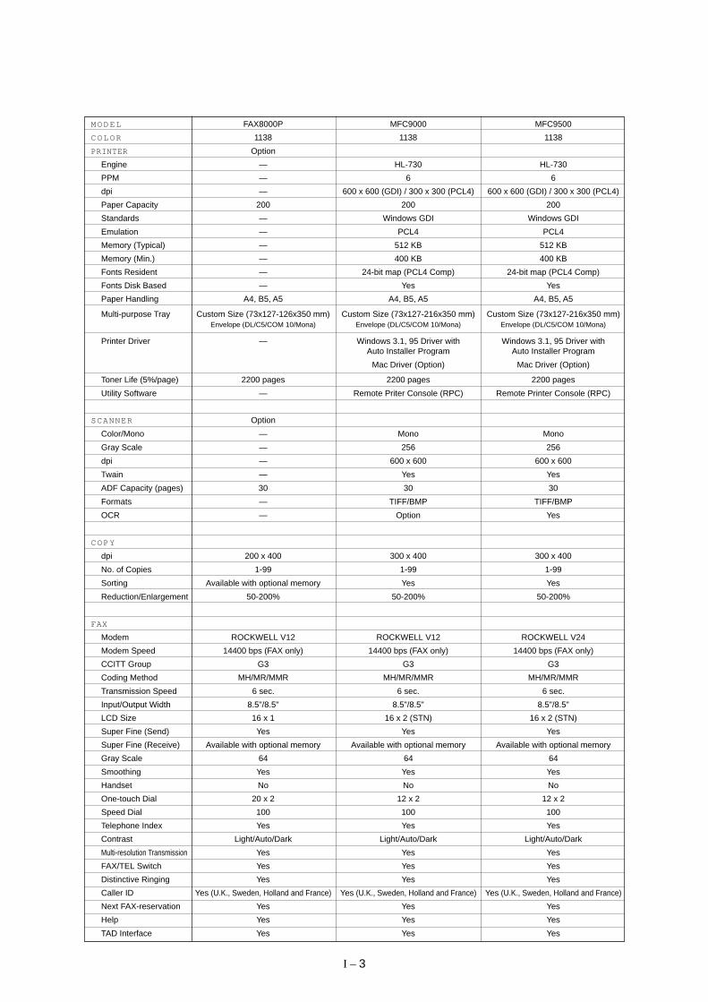
M O D E L FAX8000P MFC9000 MFC9500
C O L O R 1138 1138 1138
PRINTER Option
Engine — HL-730 HL-730
PPM — 6 6
dpi — 600 x 600 (GDI) / 300 x 300 (PCL4) 600 x 600 (GDI) / 300 x 300 (PCL4)
Paper Capacity 200 200 200
Standards — Windows GDI Windows GDI
Emulation — PCL4 PCL4
Memory (Typical) — 512 KB 512 KB
Memory (Min.) — 400 KB 400 KB
Fonts Resident — 24-bit map (PCL4 Comp) 24-bit map (PCL4 Comp)
Fonts Disk Based — Yes Yes
Paper Handling A4, B5, A5 A4, B5, A5 A4, B5, A5
Multi-purpose Tray Custom Size (73x127-126x350 mm) Custom Size (73x127-216x350 mm) Custom Size (73x127-216x350 mm)Envelope (DL/C5/COM 10/Mona) Envelope (DL/C5/COM 10/Mona) Envelope (DL/C5/COM 10/Mona)
Printer Driver — Windows 3.1, 95 Driver with Windows 3.1, 95 Driver withAuto Installer Program Auto Installer Program
Mac Driver (Option) Mac Driver (Option)
Toner Life (5%/page) 2200 pages 2200 pages 2200 pages
Utility Software — Remote Priter Console (RPC) Remote Printer Console (RPC)
SCANNER Option
Color/Mono — Mono Mono
Gray Scale — 256 256
dpi — 600 x 600 600 x 600
Twain — Yes Yes
ADF Capacity (pages) 30 30 30
Formats — TIFF/BMP TIFF/BMP
OCR — Option Yes
C O P Y
dpi 200 x 400 300 x 400 300 x 400
No. of Copies 1-99 1-99 1-99
Sorting Available with optional memory Yes Yes
Reduction/Enlargement 50-200% 50-200% 50-200%
FAX
Modem ROCKWELL V12 ROCKWELL V12 ROCKWELL V24
Modem Speed 14400 bps (FAX only) 14400 bps (FAX only) 14400 bps (FAX only)
CCITT Group G3 G3 G3
Coding Method MH/MR/MMR MH/MR/MMR MH/MR/MMR
Transmission Speed 6 sec. 6 sec. 6 sec.
Input/Output Width 8.5"/8.5" 8.5"/8.5" 8.5"/8.5"
LCD Size 16 x 1 16 x 2 (STN) 16 x 2 (STN)
Super Fine (Send) Yes Yes Yes
Super Fine (Receive) Available with optional memory Available with optional memory Available with optional memory
Gray Scale 64 64 64
Smoothing Yes Yes Yes
Handset No No No
One-touch Dial 20 x 2 12 x 2 12 x 2
Speed Dial 100 100 100
Telephone Index Yes Yes Yes
Contrast Light/Auto/Dark Light/Auto/Dark Light/Auto/Dark
Multi-resolution Transmission Yes Yes Yes
FAX/TEL Switch Yes Yes Yes
Distinctive Ringing Yes Yes Yes
Caller ID Yes (U.K., Sweden, Holland and France) Yes (U.K., Sweden, Holland and France) Yes (U.K., Sweden, Holland and France)
Next FAX-reservation Yes Yes Yes
Help Yes Yes Yes
TAD Interface Yes Yes Yes

I – 4
M O D E L FAX3550 MFC4550 MFC6550MC MFC7550MC
FAX
Coverpage Yes, Super Yes, Super Yes, Super Yes, Super
Polling Type Std/Del/Seq Std/Del/Seq Std/Del/Seq Std/Del/Seq
Receive password Yes Yes Yes Yes
Delayed Transmission Yes, 3 timings Yes, 3 timings Yes, 3 timings Yes, 3 timings
Call Reservation Yes Yes Yes Yes
Callback Message Yes Yes Yes Yes
Page Memory (TX)* 300 KB (30 pgs: MMR) 200 KB (20 pgs: MMR) 300 KB (30 pgs: MMR) 700 KB (70 pgs: MMR)
Out-of-paper Reception* 400 KB (40 pgs: MMR) 400 KB (40 pgs: MMR) 600 KB (60 pgs: MMR) 1.5 MB (150 pgs: MMR)
Super Quick Scan Yes Yes Yes Yes
Auto Reduction Yes Yes Yes Yes
ECM Yes Yes Yes Yes
Broadcasting Yes Yes Yes Yes
Multi Transmission Yes Yes Yes Yes
MESSAGE CENTER
TAD Feature No No Yes (Hardware & PC) Yes (Hardware & PC)
ICM Recording Time No No Hardware: 15 min. Hardware: 30 min.
Paging No No Yes (Hardware & PC) Yes (Hardware & PC)
Toll Saver No No Yes (Hardware & PC) Yes (Hardware & PC)
OGM No No Yes (Hardware & PC) Yes (Hardware & PC)
Mail Box No No Yes (PC only) Yes (PC only)
Fax-on-demand No No Yes (PC only) Yes (PC only)
Voice-on-demand No No Yes (PC only) Yes (PC only)
FAX Forwarding Yes Yes Yes Yes
FAX Retrieval Yes Yes Yes Yes
MACHINE MEMORY 0.75 MB 0.75 MB 1 MB 2 MB
OPTIONAL MEMORY 1 or 2 MB 1 or 2 MB 1 or 2 MB 1 or 2 MB
(FAX & PRINTER FLEX)
PC FAX (Send/Receive) Option Yes (by M/L) Yes (by M/L) Yes (by M/L)
Standard — Class 1, 2 Class 1, 2 Class 1, 2
DATA MODEM No No No No
INTERFACE
Printer Interface — Centronics parallel (w/o cable) Centronics parallel (w/o cable) Centronics parallel (w/o cable)
MULTI-FUNCTION LINK PRO MULTI-FUNCTION LINK PRO MULTI-FUNCTION LINK PRO
PC Interface RS-232C — — —(8-pin modular connector)
MULTI-FUNCTION LINK
Extended I/O Interface — — RS-232C and RS-422 RS-232C and RS-422(supported by an optional serial (supported by an optional serialinterface board RS-100M) interface board RS-100M)
Simultaneous
Sends FAX and Prints — Yes Yes Yes
Receives FAX and Prints — Yes Yes Yes
Receives FAX and Scans — Yes Yes Yes
Prints and Scans — Yes Yes Yes
Receives FAX and Copies — Yes Yes Yes
Prints and Copies — Yes Yes Yes
* CCITT#1 Chart in the Standard Mode, MMR
I – 5
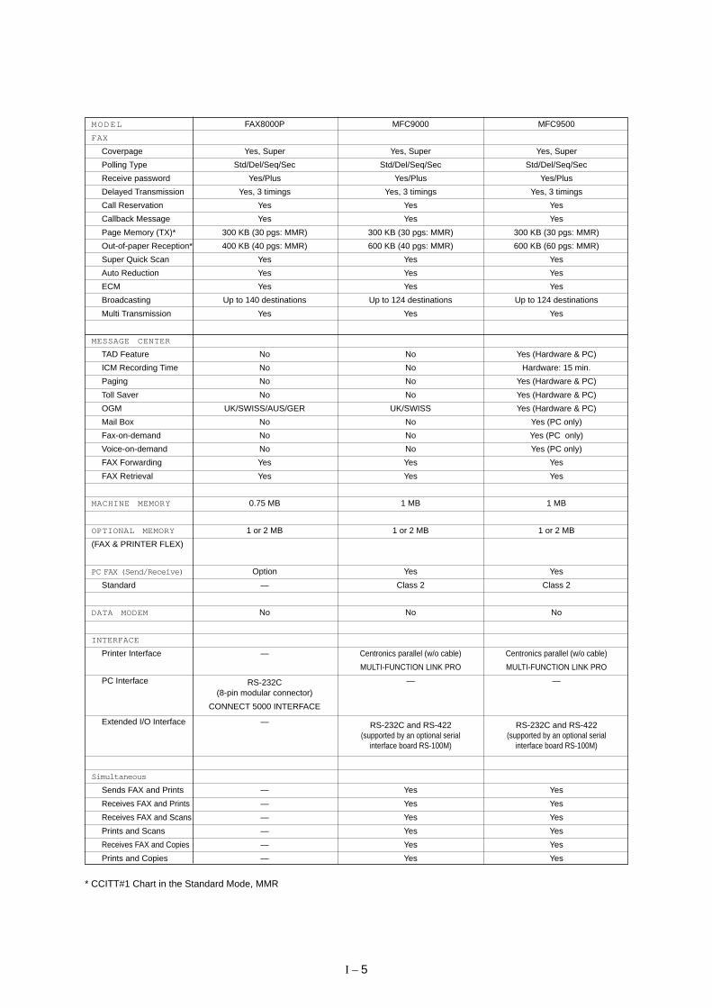
M O D E L FAX8000P MFC9000 MFC9500
FAX
Coverpage Yes, Super Yes, Super Yes, Super
Polling Type Std/Del/Seq/Sec Std/Del/Seq/Sec Std/Del/Seq/Sec
Receive password Yes/Plus Yes/Plus Yes/Plus
Delayed Transmission Yes, 3 timings Yes, 3 timings Yes, 3 timings
Call Reservation Yes Yes Yes
Callback Message Yes Yes Yes
Page Memory (TX)* 300 KB (30 pgs: MMR) 300 KB (30 pgs: MMR) 300 KB (30 pgs: MMR)
Out-of-paper Reception* 400 KB (40 pgs: MMR) 600 KB (40 pgs: MMR) 600 KB (60 pgs: MMR)
Super Quick Scan Yes Yes Yes
Auto Reduction Yes Yes Yes
ECM Yes Yes Yes
Broadcasting Up to 140 destinations Up to 124 destinations Up to 124 destinations
Multi Transmission Yes Yes Yes
MESSAGE CENTER
TAD Feature No No Yes (Hardware & PC)
ICM Recording Time No No Hardware: 15 min.
Paging No No Yes (Hardware & PC)
Toll Saver No No Yes (Hardware & PC)
OGM UK/SWISS/AUS/GER UK/SWISS Yes (Hardware & PC)
Mail Box No No Yes (PC only)
Fax-on-demand No No Yes (PC only)
Voice-on-demand No No Yes (PC only)
FAX Forwarding Yes Yes Yes
FAX Retrieval Yes Yes Yes
MACHINE MEMORY 0.75 MB 1 MB 1 MB
OPTIONAL MEMORY 1 or 2 MB 1 or 2 MB 1 or 2 MB
(FAX & PRINTER FLEX)
PC FAX (Send/Receive) Option Yes Yes
Standard — Class 2 Class 2
DATA MODEM No No No
INTERFACE
Printer Interface — Centronics parallel (w/o cable) Centronics parallel (w/o cable)
MULTI-FUNCTION LINK PRO MULTI-FUNCTION LINK PRO
PC Interface RS-232C — —(8-pin modular connector)
CONNECT 5000 INTERFACE
Extended I/O Interface — RS-232C and RS-422 RS-232C and RS-422(supported by an optional serial (supported by an optional serial
interface board RS-100M) interface board RS-100M)
Simultaneous
Sends FAX and Prints — Yes Yes
Receives FAX and Prints — Yes Yes
Receives FAX and Scans — Yes Yes
Prints and Scans — Yes Yes
Receives FAX and Copies — Yes Yes
Prints and Copies — Yes Yes
* CCITT#1 Chart in the Standard Mode, MMR

CHAPTER II .
INSTALLATION
CHAPTER III .
THEORY OF OPERATION

CONTENTS
1. OVERVIEW .................................................................................................... III -1
2. MECHANISMS ............................................................................................... III -2
2.1 Scanner Mechanism ............................................................................... III -3
2.1.1 Document feeding and ejecting mechanism ................................... III -3
2.1.2 Document scanning mechanism ..................................................... III -3
2.2 Laser Printing Mechanism ...................................................................... III -4
2.2.1 Paper pulling-in, registration, feeding, and ejecting mechanism ..... III -4
2.2.2 Print process mechanism ................................................................ III -6
(1) Charging process ..................................................................... III -7
(2) Exposing process ..................................................................... III -7
(3) Developing process ................................................................. III -8
(4) Transferring process ................................................................ III -8
(5) Erasing process ....................................................................... III -8
2.2.3 Heat-fixing mechanism .................................................................... III -9
2.3 Sensors and Actuators ........................................................................... III -10
3. CONTROL ELECTRONICS ........................................................................... III -12
3.1 Configuration .......................................................................................... III -12
3.2 Main PCB ............................................................................................... III -13
3.3 Relay PCB .............................................................................................. III -22
3.4 NCU PCB ............................................................................................... III -23
3.5 Control Panel PCB ................................................................................. III -26
3.6 Power Supply PCBs ............................................................................... III -27
[ 1 ] Low-voltage power supply PCB .................................................. III -27
[ 2 ] High-voltage power supply PCB.................................................. III -28

III – 1
1. OVERVIEW
Fax Control Section Laser Printing Control Section
PC/AT MAC
RS-232C RS-422
NCU
Handset
Line Speaker
Fax data
Printer data
AC
Control panel
Scanner unit Paper feeding mechanism
Low- and high-voltage power supplies
Laser printing unit
RS-232C (Modular connector)
Centronics parallel interface Optional serial interface
(Extended I/O connector)
[MFC6550MC/7550MC/9000/9500]
[FAX3550/8000P] [MFC4550/6550MC/7550MC/9000/9500]
- LED array - CCD unit - Scanner motor
Charging, exposing, developing, transferring, erasing, and heat-fixing processes
- Electrical charger - Laser unit (including the polygon motor) - Laser-sensitive drum - Developer roller - Transfer roller - Eraser lamp - Heater roller - Main motor

III – 2
2. MECHANISMS
The equipment is classified into the following mechanisms:
SCANNER MECHANISM – Document feeding and ejecting mechanism
– Document scanning mechanism
LASER PRINTING MECHANISM – Paper pulling-in, registration, feeding, andejecting mechanisms
– Print process mechanism (consisting ofcharging, exposing, developing, transferring,and erasing processes)
– Heat-fixing mechanism
SENSORS AND ACTUATORS
Paper pulling-in andregistration mechanism
Paper ejecting mechanism
Print process mechanism
Heat-fixing mechanism
Document scanningmechanism
Document feedingand ejecting mecha-nism SCANNER
MECHANISM
With paper feedingmechanism
LASER PRINTINGMECHANISM

III – 3
2.1 Scanner Mechanism
Document stacker
Document feed roller ASSY
Document pressure bar
Document take-in roller ASSY
2nd mirror
Separation roller ASSY
LED array
1st mirror
Document tray
(Front)
Document scanningmechanism
Document feeding andejecting mechanism
Document ejection roller ASSY
DocumentADF parts
Document rear sensor actuator
2.1.1 Document feeding and ejecting mechanism
This mechanism consists of the document stacker, automatic document feeder (ADF), docu-ment feed roller ASSY, and document sensors. (For details about the sensors, refer to Sec-tion 2.3.)
If the operator sets documents on the document stacker and starts the scanning operation,the scanner motor rotates so that the ADF (which consists of the document take-in rollerASSY, separation roller ASSY, ADF parts and nip-related parts) feeds those documents intothe equipment, starting from the bottom sheet to the top, page by page. Each documentadvances with the document feed roller ASSY to the scanner, and then it is fed out of theequipment with the document ejection roller ASSY.
2.1.2 Document scanning mechanism
The scanner uses a charge coupled device (CCD) image sensor.
As illustrated above, the LED array illuminates a document and the reflected light of thescanned image data is transmitted via the mirrors into the lens which reduces the scanneddata so as to form the image on the CCD.
Document front sensor actuator
Nip-relatedparts
Lens
CCD unit

III – 4
2.2 Laser Printing Mechanism
2.2.1 Paper pulling-in, registration, feeding, and ejecting mechanism
Pull-in roller drive gear
Main motor
Gear drive unit
Heater roller drive gear
Paper ejectionroller drive gear
Drum drive gear
Laser-sensitive drum
Multi-purposesheet feeder
Paper ejecting mechanism
Paper pulling-in and registration mechanism
Paper feeding mechanism
Sheet feeder coverPaper
Pull-in roller
Hopper
Registration sensor actuator
Registration roller
Paper trayHeater roller
Paper ejection roller
Paper ejectionsensor actuator
III – 5
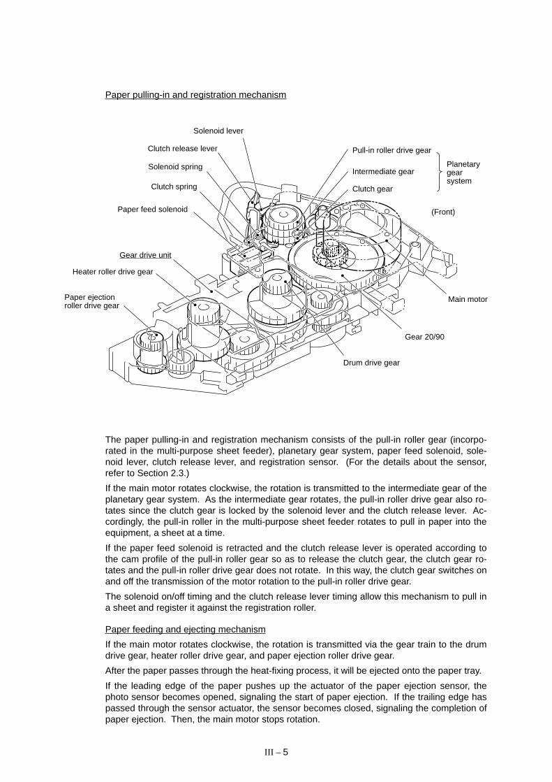
Paper pulling-in and registration mechanism
The paper pulling-in and registration mechanism consists of the pull-in roller gear (incorpo-rated in the multi-purpose sheet feeder), planetary gear system, paper feed solenoid, sole-noid lever, clutch release lever, and registration sensor. (For the details about the sensor,refer to Section 2.3.)
If the main motor rotates clockwise, the rotation is transmitted to the intermediate gear of theplanetary gear system. As the intermediate gear rotates, the pull-in roller drive gear also ro-tates since the clutch gear is locked by the solenoid lever and the clutch release lever. Ac-cordingly, the pull-in roller in the multi-purpose sheet feeder rotates to pull in paper into theequipment, a sheet at a time.
If the paper feed solenoid is retracted and the clutch release lever is operated according tothe cam profile of the pull-in roller gear so as to release the clutch gear, the clutch gear ro-tates and the pull-in roller drive gear does not rotate. In this way, the clutch gear switches onand off the transmission of the motor rotation to the pull-in roller drive gear.
The solenoid on/off timing and the clutch release lever timing allow this mechanism to pull ina sheet and register it against the registration roller.
Paper feeding and ejecting mechanism
If the main motor rotates clockwise, the rotation is transmitted via the gear train to the drumdrive gear, heater roller drive gear, and paper ejection roller drive gear.
After the paper passes through the heat-fixing process, it will be ejected onto the paper tray.
If the leading edge of the paper pushes up the actuator of the paper ejection sensor, thephoto sensor becomes opened, signaling the start of paper ejection. If the trailing edge haspassed through the sensor actuator, the sensor becomes closed, signaling the completion ofpaper ejection. Then, the main motor stops rotation.
Paper ejectionroller drive gear
Gear drive unit
Heater roller drive gear
Drum drive gear
Gear 20/90
Main motor
Pull-in roller drive gear
Intermediate gear
Clutch gear
Solenoid spring
Clutch release lever
Solenoid lever
Clutch spring
Paper feed solenoid (Front)
Planetarygearsystem

III – 6
2.2.2 Print process mechanism
The print process unit works with laser beam, electrical charges, and toner. The graph be-low shows the transition of electrical charge on the surface of the laser-sensitive drumthrough the five processes: charging, exposing, developing, transferring, and erasing pro-cesses.
+1000
+700
+400
+300
1 2 3 4
(a)
(b)
Time
A single cycle of laser-sensitivedrum operation
Ele
ctric
al c
harg
e on
the
drum
sur
face
(V
) 1 Charges the drum surface positively.
2 Exposes the drum surface to a laser beam toform a latent image and develops the latentimage with toner.
a) Unexposed area (Non-image area)b) Exposed area (Image area)
3 Transfers the toner-formed image from thedrum to paper.
4 Erases the residual potential.
Paper Transfer roller
Drum unit
Laser-sensitive drum
Cleaner roller
Charger (Corona wire)
Toner sensor
Toner cartridge
Cover glass
Laser unit
Polygon mirror
Polygon motor Mirror
Mirror
Toner augers
Developerroller
Toner supplyroller

III – 7
(1) Charging process
The high-voltage power supply applies DC bias to the corona wire to generate ion on thegrid. The ion uniformly charges the surface of the laser-sensitive drum to approx. 1000Vwhich is kept by the varister grounding the grid to the frame.
+++
++ + + + +
++
+++
+++
+ + ++
------- - - - -
Laser-sensitive layer
Aluminum drum
DrumGrid
Varister
Corona wire
High-voltagepower source
Approx. 280VPositive chargingsource
Paper
Laser-sensitive drum
Laser beam
f θ lens
Polygon mirror
Polygon motor
Lens
Laser diode
Laser detector
Laser beam
(2) Exposing process
When the laser-sensitive drum holds a positive electrical charge, the laser beam issued fromthe laser unit scans the drum according to the print image to expose the drum surface forneutralizing the spots where black should be, forming an electrostatic latent image.
Approx. 1000V

III – 8
(3) Developing process
The developing process develops an electrostatic latent image formed on the drum in theexposing process, into a toner image.
The developer roller attracts the toner particles fed from the toner cartridge by the toner sup-ply roller, and then conveys them to the contact section with the laser-sensitive drum.
On the contact section between the developer roller and drum, the positive toner particlesstick to the neutralized spots on the drum according to the principles of attraction and repul-sion, transforming a latent image into a toner image.
The toner augers (which agitate toner particles in the chamber) and the blade allow tonerparticles to be fed onto the developer roller at an even thickness.
Laser-sensitivedrum
DC biasToner supply roller
Eraser lamp
Transfer roller
Switch “a” (ON for thetransfer process)
Switch “b” (ON for repulsingtoner from the transfer roller)
(4) Transferring process
When a paper passes between the drum and the transfer roller, the switch “a” (see theabove illustration) is turned on to negatively charge the transfer roller. The toner is positive,so the toner image formed on the drum will be transferred onto the paper according to thesame principle as for the developing process.
If the toner image fails to stick to the paper due to paper jam or other errors, it will stick to thetransfer roller. To repulse this toner, the switch “b” (see the above illustration) is turned on topositively charge the transfer roller. The toner returns from the transfer roller to the drum.
Cleaning the drum
In the transferring process, not all the toner particles on the drum are transferred onto thepaper but some toner particles remain on the drum. The cleaner roller cleans the drum sur-face and collects the residual toner. When printing starts or during non-printing, the tonercollected on the cleaner roller will be discharged onto the drum and returned to the chamberthrough the developer roller for recycling in the subsequent developing process.
(5) Erasing process
The eraser lamp emits light to expose the drum surface, which erases the residual electricalcharge.
Toner augers
Blade
Developerroller
Cleaner roller
Chamber
Toner

III – 9
2.2.3 Heat-fixing mechanism
Pressure roller
(Paper ejection roller)
Paper
(Paper ejection sensor actuator)Heat-fixing unit
Heater roller(including the FU lamp)
As the paper passes between the heater roller and the pressure roller in the fixing unit, theheater roller fuses the toner on the paper.

III – 10
2.3 Sensors and Actuators
This equipment has ten sensors: two microswitches, six photosensors and two thermistersas described below.
Sensor name Type Located on
Hook switch sensor Microswitch Hook switch PCB
Cover sensor Microswitch Relay PCB
Registration sensor Photosensor (PC1) Relay PCB
Sheet feeder cover sensor Photosensor (PC2) Relay PCB
Paper ejection sensor Photosensor (PC1) High-voltage power supply PCB
Document front sensor Photosensor (PC1) Document sensor PCB
Document rear sensor Photosensor (PC2) Document sensor PCB
Toner sensor Photosensor (PH1) Toner sensor PCB (on the laser unit)
Toner thermister P1 Toner sensor PCB (on the laser unit)
Heater thermister __ Fixing unit
• Hook switch sensor which detects whether the handset is placed on the handset mount.
• Cover sensor which detects whether the top cover is closed.
• Registration sensor which detects the leading and trailing edges of paper, which allowsthe controller to determine the registration timing and check paper jam.
• Sheet feeder cover sensor which detects whether the sheet feeder cover is closed.
• Paper ejection sensor which detects whether the recording paper goes out of the equip-ment.
• Document front sensor which detects the presence of documents.
• Document rear sensor which detects the leading and trailing edges of pages to tell thecontrol circuitry when the leading edge of a new page has reached the starting positionand when the scan for that page is over.
• Toner sensor which detects whether there is toner or a toner cartridge is loaded.
• Toner thermister which detects the temperature of the toner cartridge.
• Heater thermister which detects the temperature of the heater roller of the fixing unit.
These photosensors are a photointerrupter consisting of a light-emitting diode and a light-sensitive transistor. Each of them has an actuator separately arranged as shown on the nextpage.

III – 11
Hook switch sensor(Microswitch)Hook switch sensoractuator
(Low-voltage powersupply PCB)
(Main PCB)
(Relay PCB)Toner thermister(On back of PCB)
Toner sensor
Registration sensor actuatorRegistration sensor (Photosensor)
(Eraser lamp board)
(Fixing unit)
(Document sensor PCB)
Document front sensor actuatorDocument front sensor (Photosensor)
(TonersensorPCB)
Sheet feeder cover sensor actuatorSheet feeder cover sensor(Photosensor)
Cover sensor actuatorCover sensor (Microswitch)
(High-voltage powersupply PCB)
Document rear sensor actuatorDocument rear sensor(Photosensor)
Heater thermister
Paper ejection sensoractuatorPaper ejection sensor(Photosensor)
Location of Sensors and Actuators
III – 12
3. CONTROL ELECTRONICS
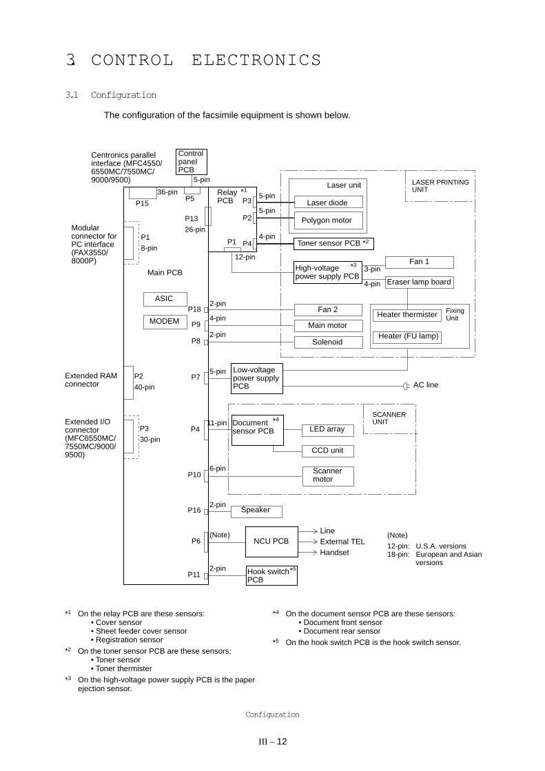
3.1 Configuration
The configuration of the facsimile equipment is shown below.
Main PCB
ControlpanelPCB
RelayPCB
*1
ASIC
MODEM
Laser unit
Toner sensor PCB *2
FixingUnitHeater thermister
Heater (FU lamp)
Fan 2
Main motor
Solenoid
AC line
Low-voltagepower supplyPCB
Documentsensor PCB
*4
CCD unit
LED array
Scannermotor
Speaker
NCU PCBLineExternal TELHandset
36-pin
P15
P1
8-pin
P2
40-pin
P3
30-pin
5-pin
P5
P13
26-pin
P182-pin
4-pinP9
P82-pin
P75-pin
P411-pin
P106-pin
P162-pin
P6(Note)
P112-pin
5-pin
5-pin
4-pin
12-pin
High-voltagepower supply PCB
*3 Fan 1
Eraser lamp board
3-pin
4-pin
LASER PRINTINGUNIT
SCANNERUNIT
P1
P3
P2
P4
Modularconnector forPC interface(FAX3550/8000P)
*1 On the relay PCB are these sensors:• Cover sensor• Sheet feeder cover sensor• Registration sensor
*2 On the toner sensor PCB are these sensors:• Toner sensor• Toner thermister
*3 On the high-voltage power supply PCB is the paperejection sensor.
*4 On the document sensor PCB are these sensors:• Document front sensor• Document rear sensor
*5 On the hook switch PCB is the hook switch sensor.
Configuration
Polygon motor
Laser diode
*5Hook switchPCB
Centronics parallelinterface (MFC4550/6550MC/7550MC/9000/9500)
Extended I/Oconnector(MFC6550MC/7550MC/9000/9500)
Extended RAMconnector
(Note)
12-pin: U.S.A. versions18-pin: European and Asian
versions

III – 13
Centronicsparallel interface
(FAX3550/8000P)
DRAM(s)
ROMs
Extended RAMconnector
MODEM
Extended I/Oconnector foroptional serialinterface board(RS-232C andRS-422)
E2PROM(s)
Analog switchoperationalamplifiers
Amplifiers
Scannermotor driver
Imageprocessor
Main motordriver
Fan 2
Main motor
Solenoid
Low-voltagepower supplyPCB
Documentsensor PCB
Scannermotor
Speaker
NCU PCB
Hook switchPCB
Main PCB
ASIC
Relay PCB
Control panel
3.2 Main PCB
The main PCB, which is the nucleus controlling the entire operation of the equipment, con-sists of a FAX engine (ASIC), memories, MODEM, motor drive circuits, sensor detection cir-cuitry, and analog circuits for scanning, printing, and power transmission shifting.
E2PROM: Electrically Erasable Programmable Read-only MemoryDRAM: Dynamic Random Access Memory
Block Diagram of Main PCB
(MFC4550/6550MC/7550MC/9000/9500)
Modularconnector for PC interface(RS-232C)
(MFC6550MC/7550MC/9000/9500)

III – 14
Main PCB Circuit Diagram 1/7
1 FAX engine (ASIC) which manages the I/Os, memories, drivers and image proces-sor as well as controlling the laser printing unit.
2 8-pin modular connector for the PC interface (RS-232C), provided on the FAX3550/8000P only.
1
2

III – 15
E2PROM No.#2 #3
Model
FAX3550 16K x 1 bit 16K x 1 bit
MFC4550 –– 16K x 1 bit
MFC6550MC –– 16K x 1 bit
FAX8000P/MFC6550MC/ 16K x 1 bit 16K x 1 bit9000/9500
1
2
3
4
5
6
#12
#15
#11
#10
#2 #3
DRAM No.#10 #11 #12 #15
Model
FAX3550/MFC4550 –– 4M x 8 bits 4M x 8 bits ––
FAX8000P/MFC6550MC/ –– 4M x 8 bits 4M x 8 bits ––9000/9500
MFC7550MC –– –– –– 16M x 16 bits
–– : Not installed4 E2PROMs which store user settings.
Main PCB Circuit Diagram 2/7
1 ROM (8-megabit, 512K x 16 bits) which stores programs.2 ROM (8-megabit, 512K x 16 bits)
FAX3550/8000P/MFC4550:This ROM is used only on the qualification machines for demonstration.MFC6550MC/7550MC/9000/9500:This ROM stores the PCL4 (Driver programs for high-quality print).
3 DRAMs
–– : Not installed
5 Extended RAM port which allows you to add a memory up to two megabytes.6 Extended I/O connector for an optional serial interface board RS-100M which supports
the RS-232C and RS-422. (Only for the MFC6550MC/7550MC/9000/9500)
III – 16
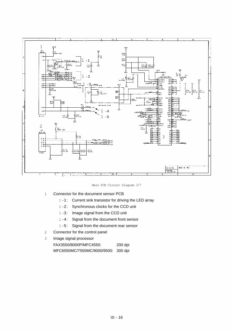
Main PCB Circuit Diagram 3/7
1 Connector for the document sensor PCB
1 -1 : Current sink transistor for driving the LED array
1 -2 : Synchronous clocks for the CCD unit
1 -3 : Image signal from the CCD unit
1 -4 : Signal from the document front sensor
1 -5 : Signal from the document rear sensor
2 Connector for the control panel
3 Image signal processor
FAX3550/8000P/MFC4550: 200 dpi
MFC6550MC/7550MC/9000/9500: 300 dpi
1
2
3
1 - 1
1 - 4
1 - 5
1 - 3
1 - 2
III – 17
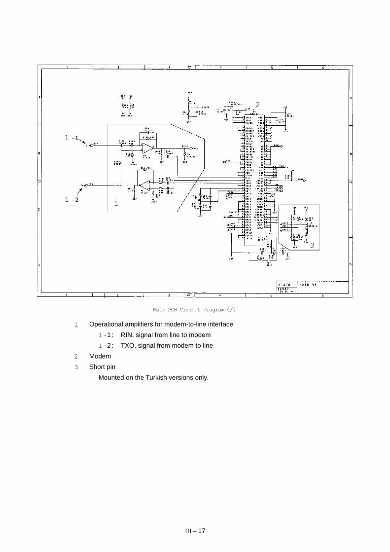
Main PCB Circuit Diagram 4/7
1 Operational amplifiers for modem-to-line interface
1 -1 : RIN, signal from line to modem
1 -2 : TXO, signal from modem to line
2 Modem
3 Short pin
Mounted on the Turkish versions only.
1
2
3
1 - 1
1 - 2
III – 18
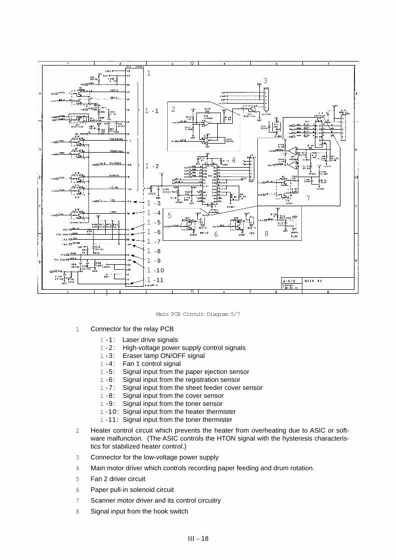
Main PCB Circuit Diagram 5/7
1 Connector for the relay PCB
1 -1 : Laser drive signals1 -2 : High-voltage power supply control signals1 -3 : Eraser lamp ON/OFF signal1 -4 : Fan 1 control signal1 -5 : Signal input from the paper ejection sensor1 -6 : Signal input from the registration sensor1 -7 : Signal input from the sheet feeder cover sensor1 -8 : Signal input from the cover sensor1 -9 : Signal input from the toner sensor1 -10: Signal input from the heater thermister1 -11: Signal input from the toner thermister
2 Heater control circuit which prevents the heater from overheating due to ASIC or soft-ware malfunction. (The ASIC controls the HTON signal with the hysteresis characteris-tics for stabilized heater control.)
3 Connector for the low-voltage power supply
4 Main motor driver which controls recording paper feeding and drum rotation.
5 Fan 2 driver circuit
6 Paper pull-in solenoid circuit
7 Scanner motor driver and its control circuitry
8 Signal input from the hook switch
1
2
3
4
5
6
7
8
1 - 1
1 - 2
1 - 3
1 - 4
1 - 5
1 - 6
1 - 7
1 - 8
1 - 9
1 - 10
1 - 11
III – 19
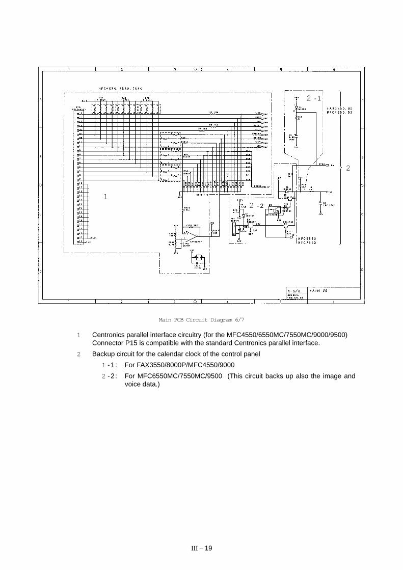
Main PCB Circuit Diagram 6/7
1 Centronics parallel interface circuitry (for the MFC4550/6550MC/7550MC/9000/9500)Connector P15 is compatible with the standard Centronics parallel interface.
2 Backup circuit for the calendar clock of the control panel
1 -1 : For FAX3550/8000P/MFC4550/9000
2 -2 : For MFC6550MC/7550MC/9500 (This circuit backs up also the image andvoice data.)
1
2
2 - 1
2 - 2

III – 20
Main PCB Circuit Diagram 7/7
1 Connector for the NCU PCB
CMLL: NCU relay ON/OFF signal
PLS: Dial pulse output
TLOF: Off-hook signal which is active Low for the external telephone.
CI: Call signal which is active Low.
TXD: Line output signal from the MODEM
TLSL: Handset microphone signal
RL1: Line input signal to the MODEM
RL2: Line monitor signal
ADLC: Line current detection input
DASEND: Output level matching signal
DAST: Side tone level matching signal (Only in the European versions.)
DPS: External telephone switching signal
EAT: Earth function signal
POL: Polarity inversion detection signal
1
22 - 1
2 - 22 - 3
2 - 5
2 - 62 - 4
2 - 7
33 - 1
3 - 2
44 - 1
4 - 2

III – 21
2 Switching devices that are controlled by the ASIC
2 -1 : Device TEL. If 0, the equipment works as a telephone; if 1, it sends a fac-simile message.
2 -2 : Device HSPLY. If 0, the equipment works as a telephone; if 1, it plays backa TAD recorded message.
2 -3 : Device TADH. If 0, the equipment works regularly; if 1, it allows you torecord a message through the microphone.
2 -4 : Device CMLH. If 0, the equipment is placed in monitor mode; if 1, it is nor-mally connected to the line.
2 -5 : Device RNG. If 0, the speaker rings; if 1, it transfers control to the deviceMSL.
2 -6 : Device MSL. If 0, the speaker works for converting line signals to sound; if1, it works for playing back a TAD recorded message.
2 -7 : Device MUTE that mutes the receiver tone.
3 Speaker amplifiers
3 -1 : For FAX3550/8000P/MFC4550/9000
3 -2 : For MFC6550MC/7550MC/9500
4 Speaker volume control circuitry
4 -1 : VOL1 that controls the speaker volume to two levels: High and Low.
4 -2 : VOL2 that augments VOL1 to handle four levels: High, Medium-high, Me-dium-low, and Low. (MFC6550MC/7550MC/9500 only)
III – 22
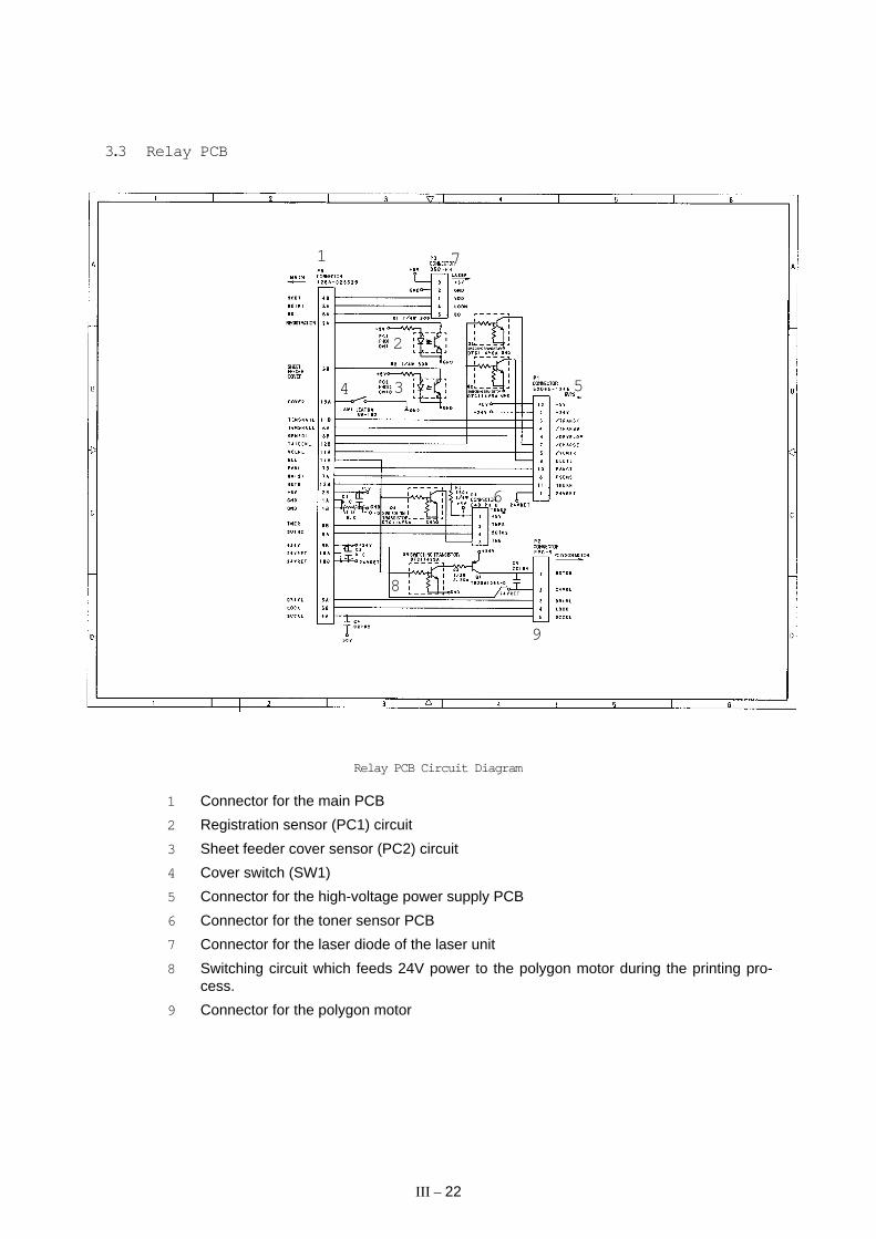
3.3 Relay PCB
1
4
6
7
8
9
Relay PCB Circuit Diagram
1 Connector for the main PCB
2 Registration sensor (PC1) circuit
3 Sheet feeder cover sensor (PC2) circuit
4 Cover switch (SW1)
5 Connector for the high-voltage power supply PCB
6 Connector for the toner sensor PCB
7 Connector for the laser diode of the laser unit
8 Switching circuit which feeds 24V power to the polygon motor during the printing pro-cess.
9 Connector for the polygon motor
5
2
3

III – 23
3.4 NCU PCB
The NCU PCB switches the communications line to telephone or built-in MODEM, under thecontrol of the main PCB.
NCU PCB Circuit Diagram (U.S.A. versions)
1 Surge absorber
2 Noise filters
3 Line relay (CML relay)
4 Line transformer
5 Circuit related to the line transformer
6 High-impedance transformer circuit
7 Calling signal detector
8 Loop current detector
9 Dial pulse generator
: Telephone circuit
a Reference voltage generation circuit for the operational amplifier in ∞ .
1 23 4 5
6
7
8
9
:
2
2
a

III – 24
NCU PCB Circuit Diagram (European versions)
1 Surge absorber
2 Noise filters
3 Line relay (CML relay)
4 Line transformer
5 Circuit related to the line transformer
6 High-impedance transformer circuit
7 Calling signal detector
8 Loop current detector
9 Dial pulse generator & loop current detector
: Telephone circuit
a Reference voltage generation circuit for the operational amplifier in ∞ .
b Pulse shaper
c Line current detection input circuit
1
2
2
2
2
2
3 4
5
6
7
8
9
:
a
c
b
2
2
3

III – 25
• The primary function of the NCU (which is shared by facsimile and telephone units) is toswitch a line to the facsimile unit or to the telephone, which is carried out by the line relay.
• Since the direct connection of a facsimile equipment to the line is not allowed for protect-ing the line, it is essential to insert a line transformer between the line and the facsimileequipment to insulate them from each other in the direct current band.
The above two components, line relay and line transformer, are the minimum requirementsfor the NCU of the facsimile equipment.
• If an external telephone is connected to the facsimile equipment, the NCU should have aloop current detector to identify the hook state by detecting the loop current.
• If the facsimile equipment has an automatic answering facility (TAD), the NCU should beequipped with a calling signal detector which detects a calling signal and tells it to theCPU in the FAX engine (ASIC).
• The circuit related to a line transformer allows the line transformer to be invariant by se-lecting the constants of the parts in this circuit so as to conform to the communicationsregulations or codes of each country.
In addition to the above basic components of the NCU, the following components are alsorequired depending upon additional functions of the facsimile equipment:
• The dial pulse generator generates dial pulses within the facsimile equipment.
• The surge absorber is a protection circuit which absorbs lightning surges.
• The noise filter eliminates noise including radiation noise in order to prevent them fromflowing out onto the communications line.
• The high-impedance transformer circuit detects the remote activation, and F/T switchingsent from the line in ON-HOOK state without any interference to the line.
• The telephone circuit includes an amplifier that amplifies output signals of the handset mi-crophone. It also includes a transistor that amplifies receive signals from the communica-tions lines to sound the handset receiver.

III – 26
3.5 Control Panel PCB
The control panel PCB and the main PCB communicate with each other by serially transmit-ting commands and data.
The control panel unit consists of a gate array, an LCD, and LEDs, which are controlled bythe gate array according to commands issued from the FAX engine on the main PCB.
The calendar clock is backed up by the backup circuit on the main PCB.
The panel FPC is a flexible keyboard PCB which integrates the key matrix having rubberkeytops.
FAXEngine
BackupCircuit
+5V
ResetCircuit
+5V POWER
I/O Ports
SerialCommunicationsPorts
RESET+5B
LEDS
Panel FPC(Key Matrix)
LCD
Main PCB Control Panel PCB
SDIN
SDOUT
PCLK
Gate Array
Control Panel PCB and its Related Circuit

III – 27
3.6 Power Supply PCBs
[ 1 ] Low-voltage power supply PCB
The low-voltage power supply uses the switching regulation system to generate DC power(+5V and +24V) from a commercial AC power supply for the driver circuits. The +5V sourceis fed to the logic, control panel, sensors, CCD unit, etc.; the 24V source is fed to the motors,solenoid, fans, LED array, and the high-voltage power supply PCB.
The low-voltage power supply also feeds AC power to the heater of the fixing unit.
Low-voltage Power Supply Circuit
Heater
Circuit
ThermalFuseLightning
Surge
Absorber
Feedback
Line
Filter
Fuse
RectifierSwitching
Circuit
24V
Detector
5V
Regulation
Circuit
24V
5V
FU lamp
(Heater)
(Driver circuits)

III – 28
[ 2 ] High-voltage power supply PCB
This power supply generates high-voltage power sources from the 24V source fed from thelow-voltage power supply for charging, developing, and transferring in the laser printing pro-cess.
High-voltage Power Supply Circuit
24VI
Control 1(TIDN TAIDEN)
Control 2(GENZ GENZOU)
Control 3A(TENH TESHAH)
Control 3B(TENL TESHAL)
GND
Fuse Type Resistor
0.221/6w
CurrentRegulator(250µA)
B1 Q1
B51 Q51
B52Q56VR53
VR33 VR31 VR34
VoltageRegulator
(600 ± 10V)
(275 ± 7V)
CurrentRegulator(-3.0µA)
VoltageRegulator(1.8kV)
VR201
VoltageRegulator(1.0kV)
Z201
910 GRID
OUT3
OUT2
OUT1
Developer Roller
Laser-sensitiveDrum
Corona Wire
12
9
10
7
6
11R1
Transfer Roller
VR101
VoltageRegulator(275V)
VR32
VoltageRegulator(700V)
VCLN8
VCLN
DRMBIAS
Cleaner Roller
Grid

CHAPTER IV .
DISASSEMBLY/REASSEMBLYAND LUBRICATION

CONTENTS
1. DISASSEMBLY/REASSEMBLY .................................................................... IV -1
Safety Precautions .................................................................................... IV-1
Preparation ................................................................................................ IV-3
How to Access the Object Component ...................................................... IV-3
Disassembly Order Flow ........................................................................... IV-4
1.1 Top Cover .............................................................................................. IV-5
1.2 Handset Mount and Hook Switch PCB (for handset-equipped versions)Side Cover (for non-handset versions) ............................................................ IV-5
1.3 Multi-purpose Sheet Feeder .................................................................. IV-6
1.4 Control Panel ASSY .............................................................................. IV-6
1.5 Panel Rear Cover and Control Panel .................................................... IV-7
1.6 Document Feed Roller ASSY and Ejection Roller ASSY....................... IV-8
1.7 Inner Cover ............................................................................................ IV-8
1.8 Scanner Frame ASSY ........................................................................... IV -10
1.9 Insulation Cover ..................................................................................... IV -12
1.10 Fixing Unit, FU Lamp, and Paper Ejection Sensor Actuator .................. IV -13
1.11 Laser Unit .............................................................................................. IV -15
1.12 Bottom Plate .......................................................................................... IV -16
1.13 Low-voltage Power Supply PCB............................................................ IV -17
1.14 High-voltage Power Supply PCB and Fan 1.......................................... IV -18
1.15 Main PCB .............................................................................................. IV -19
1.16 Relay PCB ............................................................................................. IV -21
1.17 Shield Bracket and NCU PCB ASSY ..................................................... IV -22
1.18 Gear Drive Unit ...................................................................................... IV -23
1.19 Duct Cover, Fan 2, and Speaker ........................................................... IV -25
1.20 Sheet Feeder Cover Sensor Actuator, Registration Sensor Actuator,and Cover Sensor Actuator ................................................................... IV -26
1.21 Microphone (MFC9500 only) ........................................................................... IV -27
1.22 Cleaning of High-voltage Contacts and Grounding Contacts ................ IV -28
1.23 Harness Routing .................................................................................... IV -29
2. LUBRICATION ............................................................................................... IV -30

IV – 1
1. DISASSEMBLY/REASSEMBLY
Safety Precautions
To prevent the creation of secondary problems by mishandling, observe the following pre-cautions during maintenance work.
(1) Always turn off the power before replacing parts or units. When having access to thepower supply, be sure to unplug the power cord from the power outlet.
(2) When servicing the optical system of the laser printing unit, be careful not to placescrewdrivers or other reflective objects in the path of the laser beam. Be sure to takeoff any personal accessories such as watches and rings before working on the printer.A reflected beam, though invisible, can permanently damage your eyes.
(3) If the equipment has been printing, allow the fixing unit sufficient time to cool down. It isHOT!
(4) Be careful not to lose screws, washers, or other parts removed for parts replacement.
(5) Do not remove gears from the document LF roller ASSY or ejection roller ASSY if at allpossible. Once removed, they will become unusable and new gears will have to be putback in.
(6) When using soldering irons and other heat-generating tools, take care not to damagethe resin parts such as wires, PCBs, and covers.
(7) Before handling the PCBs, touch a metal portion of the equipment to discharge staticelectricity; otherwise, the electronic parts may be damaged due to the electricitycharged in your body.
(8) When transporting PCBs, be sure to wrap them in conductive sheets such as aluminumfoil.
WARNING
For the MFC6550MC/7550MC/9500/9500 which has a nickel-hydrogen battery on themain PCB, be sure to remove that battery before transporting the PCB (in aluminiumfoil). Failure to do so may result in a short circuit, overcurrent flow, or fire.
(9) Be sure to reinsert self-tapping screws correctly, if removed.
(10) Tighten screws to the torque values listed on the next page.
(11) When connecting or disconnecting cable connectors, hold the connector bodies not thecables. If the connector has a lock, always slide the connector lock to unlock it.
(12) Before reassembly, apply the specified lubricant to the specified points. (Refer to Sec-tion 2 in this chapter.)
(13) After repairs, check not only the repaired portion but also that the connectors and otherrelated portions function properly before operation checks.

IV – 2
Tightening Torque List
Location Screw type Q'ty Tightening torque (kgf•cm)
Handset mount Taptite, cup B M3x10 2 5 ±1
Hook switch PCB Taptite, cup B M3x6 1 5 ±1
Panel rear cover Taptite, cup B M3x8 2 3 ±1
Inner cover Taptite, cup B 4x12 2 8 ±1Taptite, cup B 3x10 3 8 ±1
Scanner motor Screw, pan (washer) 3x8DB 1 7 ±2
Fixing unit Taptite, bind B 4x12 1 10 ±1Taptite, bind B 3x10 2 8 ±1
Laser unit Taptite, bind B 4x12 3 8 ±1
Toner sensor PCB Taptite, cup B 3x8 1 6 ±1
Bottom plate Taptite, cup B 4x12 5 8 ±1(On the main shield bracket) Taptite, cup S 3x6 2 5 ±1(On the gear drive unit) Taptite, cup S 3x6 2 8 ±1
Grounding wire Screw, pan (washer) 4x8DB 1 7 ±2
Low-voltage power supply PCB Taptite, bind 4x12 1 10 ±1
High-voltage power supply PCB Taptite, bind 4x12 1 10 ±1
Interface plate Taptite, bind 3x6 3 5 ±1
Relay PCB Taptite, bind B 4x12 1 10 ±1
Shield bracket Taptite, cup B 3x10 3 5 ±1
NCU PCB ASSY Taptite, cup B 3x10 1 5 ±1
Drive unit Taptite, cup B 4x20 3 12 ±1Taptite, bind B 4x12 1 10 ±1

IV – 3
Preparation
Prior to proceeding to the disassembly procedure,
(1) Unplug
- the modular jack of the telephone line,- the modular jack of the curled cord (and remove the handset), and- the modular jack of an external telephone set if mounted. (Not shown below.)
(2) Remove
- the wire extension,- the document tray,- the paper tray, and- the drum unit (with the toner cartridge loaded).
How to Access the Object Component
• On the next page is a disassembly order flow which helps you access the object compo-nent. To remove the relay PCB, for example, first find it on the flow and learn its number(f in this case). You should remove parts numbered 1, 3, b, and e so as to accessthe relay PCB.
• Unless otherwise specified, the disassembled parts or components should be reas-sembled in the reverse order of removal.
Handset and curled cord
Drum unit (with toner cartridge loaded)
Wire extension
Telephone line cordPaper tray
Document tray

IV – 4
Disassembly Order Flow
Con
trol
pan
el A
SS
Y4 5
Pan
el r
ear
cove
r-
Doc
umen
t pre
ssur
eba
r- A
DF
par
ts-
Nip
-rel
ated
par
tsC
ontr
ol p
anel
- C
ontr
ol p
anel
PC
B-
FP
C k
ey
66
Doc
umen
t fee
dro
ller A
SS
YD
ocum
ent e
ject
ion
rolle
r AS
SY
7In
ner
cove
r
8S
cann
er fr
ame
AS
SY
Doc
umen
t sen
sor
PC
B
Doc
umen
t sen
sor
actu
ator
s
Sep
arat
ion
rolle
r AS
SY
Doc
umen
t tak
e-in
rol
ler
AS
SY
Mirr
ors
Eje
ctio
n le
afsp
ring
Sca
nner
mot
or
Pre
ssur
e ro
ller
AS
SY
•S
heet
feed
erco
ver
sens
orac
tuat
or•
Reg
istr
atio
nse
nsor
act
uato
r
2017
NC
U P
CB
AS
SY
20C
over
sen
sor
actu
ator
Shi
eld
brac
ket
17
16R
elay
PC
B
Mai
n P
CB
15
- D
uct c
over
- F
an 2
- S
peak
er
19
Fan
1
14
Hig
h-vo
ltage
pow
er s
uppl
y P
CB
13
Bot
tom
pla
te12
Mul
ti-pu
rpos
esh
eet f
eede
r
3
1To
p co
ver
11La
ser
unit
Low
-vol
tage
pow
er s
uppl
yP
CB
18G
ear
driv
e un
it
Mai
n m
otor
Gea
rs
Sol
enoi
ds
14
2 2
Han
dset
mou
nt*
Sid
e co
ver*
*
Hoo
k sw
itch
PC
B*
*For
han
dset
-equ
ippe
d ve
rsio
ns**
For
non
-han
dset
ver
sion
s
Mic
roph
one
(MF
C95
00 o
nly)
21
10F
ixin
g un
itF
U la
mp
109In
sula
tion
cove
r
Pap
er e
ject
ion
sens
or a
ctua
tor

IV – 5
1.1 Top Cover
(1) Open the top cover.
(2) Push the arm of the top cover outwards with your thumb to unhook it from the maincover.
(3) Turn the top cover upright and slide it to the rear.
Arm
Main cover
Top coverturned upright
Top cover
Bosses
Main cover
(Non-handset versions)
Side cover**
Hook switch PCB*
Hook switch sensor*
Hook switch harness*
(Handset-equippedversions)
Hookswitch*
Handsetmount*
1.2 Handset Mount and Hook Switch PCB (for handset-equipped versions)Side Cover (for non-handset versions)
(1) Remove the two screws from the handset mount* or the side cover.**
(2) Twist the handset mount* or the side cover** so that it tilts over to the left and its upperend works out of the bosses provided on the main cover.
(3) To remove the hook switch PCB*, disconnect the hook switch harness* and remove thescrew.
*For handset-equipped versions**For non-handset versions

IV – 6
1.3 Multi-purpose Sheet Feeder
(1) Pull either one of the right and left tabs provided on the main cover outwards andslightly lift up the multi-purpose sheet feeder, then release the other end of the sheetfeeder also.
(2) Take up the sheet feeder.
Tab on themain cover
Tab on themain cover
Reassembling Notes
• To install the sheet feeder, align the right and left end of the front edge with the bosses ofthe main cover and then push down the rear.
Boss
Multi-purpose sheet feeder
1.4 Control Panel ASSY
(1) Slightly open the control panel ASSY as shown below.
(2) Push the right and left arms of the control panel ASSY outwards with your thumbs tounhook them from the bosses provided on the main cover, then slide the control panelASSY to the rear.
(3) Disconnect the main-panel harness from the control panel PCB.
Arm of the control panel ASSY
Control panel PCB
Control panel ASSY
Main-panel harness
Arm

IV – 7
1.5 Panel Rear Cover and Control Panel
(1) Place the control panel ASSY upside down.
(2) Remove the document pressure bar, ADF parts, and nip-related parts from the panelrear cover.
(3) Remove the two screws from the panel rear cover.
(4) While lifting up the front edge of the panel rear cover, unhook it from the 15 pawls "X"provided on the control panel.
(5) Unhook the control panel PCB from the three pawls "Y" on the control panel and take itout together with the FPC key.
FPC key
Control panel(placed upside down)
Reassembling Notes
• When installing the spring plate B and separation rubber, align their cutouts with the bosson the panel rear cover.
Document pressure bar
Spring plate B
Separation rubber
Spring plate A
Panel rear cover
15 "X" pawls
Nip-related parts
Control panel PCB
3 "Y" pawls
ADFparts

IV – 8
1.6 Document Feed Roller ASSY and Ejection Roller ASSY
(1) Push arm rib "A" to the rear, then shift the document feed roller ASSY to the right andupwards.
(2) Push arm rib "B" to the rear, then shift the document ejection roller ASSY to the rightand upwards.
Document feed roller ASSYDocument ejection roller ASSY
1.7 Inner Cover
(1) Remove the five screws.
(2) Unlatch the pawl "a" by hand.
(3) While lifting up the inner cover, unlatch the four pawls "b" and "c."
NOTE: Take care not to scratch or drop the cover glass on the scanner frame ASSY.
Inner cover
Pinch rollers
Control panel lock(Leaf spring)
Viewed fromthe left side
"b"
Sponge
"a"
"b"
"B"
"A"
"c""c"

IV – 9
Main-panel harness
Inner cover
- After installing the inner cover, be sure to put the sponge back into place.
Reassembling Notes
• Before putting the inner cover on the main cover, make sure that:
- The control panel locks (leaf springs) are set in the inner cover as shown on the previ-ous page.
- The pinch rollers are set with their fringes facing outwards as shown on the previouspage.
- The main-panel harness connector comes out from the cutout provided in the innercover as shown below.

IV – 10
1.8 Scanner Frame ASSY
(1) You can remove the following parts from the top of the scanner frame ASSY withouttaking out the ASSY from the main cover:
• Cover glass. Turn the cover glass up towards you.
• Ejection leaf springs. Remove them while slightly pulling up the front edges.
• Document take-in roller ASSY. Unhook the latch of the gear, take it off, and lift up theASSY.
• Separation roller ASSY. First unhook the latch of the adjacent gear and take it off,and then remove the separation roller ASSY in the same way as for the documenttake-in roller ASSY.
• Pressure roller ASSY. While pressing down the leaf springs, remove the ASSY.
• Bar lens and LED array.
• Document front sensor actuator.
• Document rear sensor actuator. While pressing down the leaf spring and pulling theboss "X" provided on the scanner frame ASSY to the front, slightly move the actuatorto the left and lift it up.
• Document sensor PCB. Disconnect the CCD harness and LED array harness fromthe document sensor PCB. Take the main-sensor harness out of the three clamps(see the illustration on the next page) and then disconnect it from the PCB.
PC1
PC2
P3
P1
P2
Documentsensor PCB
Document frontsensor actuator
Boss "X"Ejection leafsprings
Bar lens and LED array
CCD unit(Do not remove)
Leaf springs
Document rearsensor actuator
Document take-inroller ASSY
Separation roller ASSY
Pressure roller ASSY
Cover glass
CCD harness
(Front)
PC1: Document front sensorPC2: Document rear sensor
Main-sensor harness connector
CCD harness connector

IV – 11
(2) Before taking out the scanner frame ASSY, make sure that the cover glass is removedand the main-sensor harness is disconnected.
(3) Slightly lift up the scanner frame ASSY and disconnect the scanner motor harness fromthe motor, then take out the ASSY.
NOTE: Take care not to scratch the mirrors (see the illustration below), CCD unit, orbar lens.
NOTE: NEVER remove or replace the CCD unit. Its mounting position has been ad-justed in the factory.
Sponges
Scanner frame ASSY
Cover glass(Remove before taking out the scannerframe ASSY.)
Main-sensor harnessClamps
Documentsensor PCB
Sponge
CCD unit (Do not remove)
Scanner motor harness
Scanner motor
Mirrors
(Front)
Bar lens and LED array

IV – 12
Reassembling Notes
• Check that the mirrors and cover glass are not stained. Wipe them with a soft cloth ifnecessary.
• If you have disassembled the gear train on the right side of the scanner frame ASSY, re-assemble it referring to the illustration below.
(Rear)(Front)
Separation roller gearDocument take-inroller gear
Scanner frameASSY
Scanner motor gear
(Right side view)
• After installing the scanner frame ASSY, be sure to put the sponges back into place asshown on the previous page.
Insulation cover
Main cover
1.9 Insulation Cover
(1) Lift up the insulation cover.

IV – 13
1.10 Fixing Unit, FU Lamp, and Paper Ejection Sensor Actuator
(1) Remove the screw "a."
(2) Lift up the fixing unit and then disconnect the heater harness (blue and brown wires).Disconnect the heater thermister harness from the eraser lamp board.
(3) Remove the paper ejection sensor actuator from the main cover.
(4) To take out the FU lamp from the fixing unit, remove the two screws "b" from the fixingunit.
(5) Unhook the two latches outwards with the tip of a small flat screwdriver and open theupper cover. (See the next page.)
(6) Fully open the upper cover and remove it.
"a" "b"
"b"
Fixing unit
Blue heaterharness
Eraser lampboard
Brown heaterharness
Paper ejectionsensor actuator
Heater thermister harness
Paper ejectionsensor actuator
IV – 14
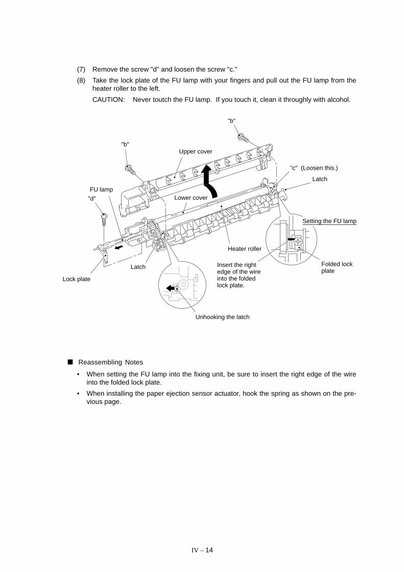
(7) Remove the screw "d" and loosen the screw "c."
(8) Take the lock plate of the FU lamp with your fingers and pull out the FU lamp from theheater roller to the left.
CAUTION: Never toutch the FU lamp. If you touch it, clean it throughly with alcohol.
Setting the FU lamp
Folded lockplate
Latch
"c" (Loosen this.)
Heater roller
Insert the rightedge of the wireinto the foldedlock plate.
Unhooking the latch
Latch
Lock plate
"d"
FU lamp
"b"
Lower cover
Upper cover
"b"
Reassembling Notes
• When setting the FU lamp into the fixing unit, be sure to insert the right edge of the wireinto the folded lock plate.
• When installing the paper ejection sensor actuator, hook the spring as shown on the pre-vious page.

IV – 15
1.11 Laser Unit
(1) Remove the three screws.
(2) Slightly lift up the laser unit and disconnect the following three things from the relayPCB:
• Laser diode harness (5-pin)
• Polygon motor flat cable (5-pin)
• Toner sensor harness (4-pin)
NOTE: When handling the laser unit, take care not to touch the inside of the unit,glass, or mirror.
On the small PCB at the right side of the laser unit is a 2-pin connector whichis for the adjustment in the factory. Do not disturb it.
Toner sensor
Toner sensor PCB
Glass
Mirror
Laser unit
Polygon motor flatcable
Laser diode harness
Toner sensor harness
Sponge
Relay PCB
Reassembling Notes
• Before putting the laser unit back into place, check for any toner particles, paper dust ordirt, and clean them out.
• When installing the laser unit, make sure that the toner sensor harness is routed throughthe groove as shown above.
• Make sure that the sponge is placed below the laser unit.

IV – 16
1.12 Bottom Plate
(1) Make sure that the drum unit, top cover, and multi-purpose sheet feeder have been re-moved.
(2) Turn the machine upside down.
(3) Remove the nine screws.
(4) Slightly lift up the bottom plate and disconnect the grounding wire.
Bottom plate
Grounding wire
Screws (Taptite, cup S3x6)
Screws (Taptite, cup B4x12)

IV – 17
1.13 Low-voltage Power Supply PCB
The illustration below shows the location of the PCBs.
Reassembling Notes
• When reassembling the above parts, make sure that the above harnesses are routedthrough the clamps provided on the main cover as illustrated in Section 1.23.
Low-voltage powersupply PCB
Gear drive unit
Fan 1
High-voltage powersupply PCB
Relay PCB
Main PCB
Main cover (placedupside down)
NCU PCB (beneath the main PCB)
(Front)
(1) Remove the screw from the low-voltage power supply PCB.
(2) Slightly lift up the low-voltage power supply PCB and pull out the power switch support.
(3) Disconnect the main–low-voltage harness and heater harness (of the blue and brownwires) from the low-voltage power supply PCB.
Main–low-voltage harness
(Rear)
Low-voltage power supply PCB
Power cord
Power switch support
Main cover (placedupside down)
Heater harness (blueand brown wires)
IV – 18
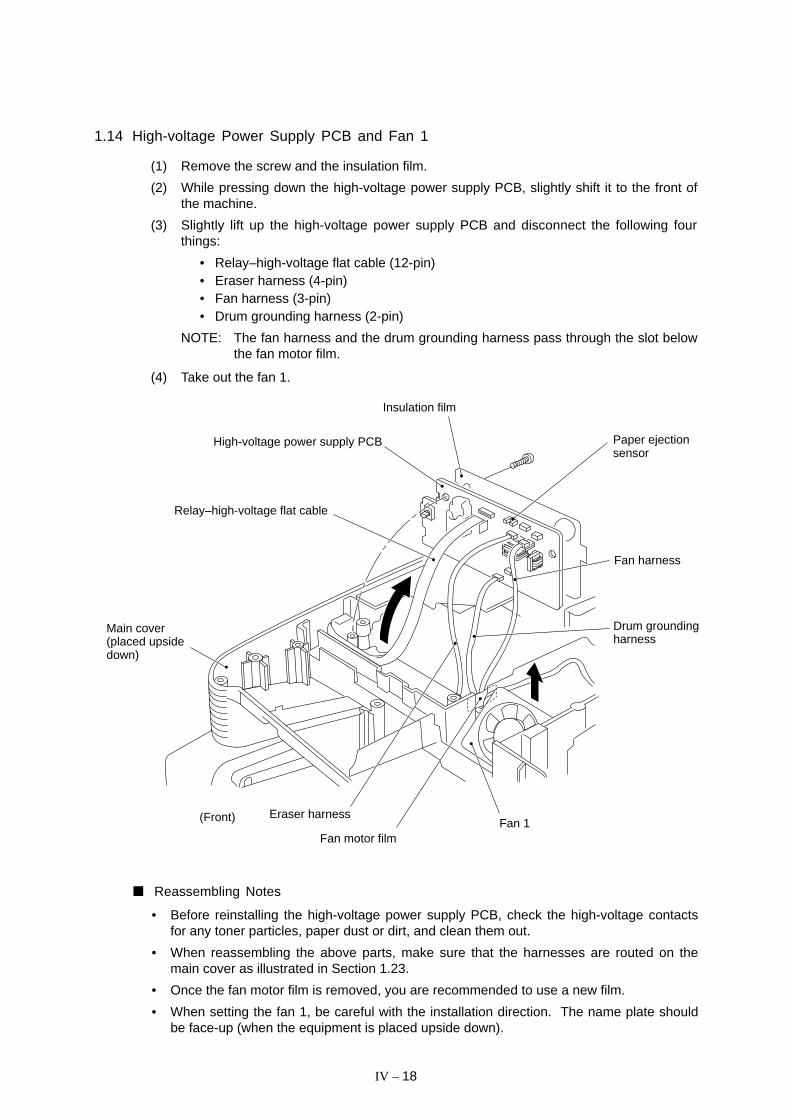
1.14 High-voltage Power Supply PCB and Fan 1
(1) Remove the screw and the insulation film.
(2) While pressing down the high-voltage power supply PCB, slightly shift it to the front ofthe machine.
(3) Slightly lift up the high-voltage power supply PCB and disconnect the following fourthings:
• Relay–high-voltage flat cable (12-pin)• Eraser harness (4-pin)• Fan harness (3-pin)• Drum grounding harness (2-pin)
NOTE: The fan harness and the drum grounding harness pass through the slot belowthe fan motor film.
(4) Take out the fan 1.
Drum groundingharness
(Front)
Relay–high-voltage flat cable
High-voltage power supply PCB
Eraser harness
Fan motor filmFan 1
Main cover(placed upsidedown)
Fan harness
Paper ejectionsensor
Insulation film
Reassembling Notes
• Before reinstalling the high-voltage power supply PCB, check the high-voltage contactsfor any toner particles, paper dust or dirt, and clean them out.
• When reassembling the above parts, make sure that the harnesses are routed on themain cover as illustrated in Section 1.23.
• Once the fan motor film is removed, you are recommended to use a new film.
• When setting the fan 1, be careful with the installation direction. The name plate shouldbe face-up (when the equipment is placed upside down).
IV – 19
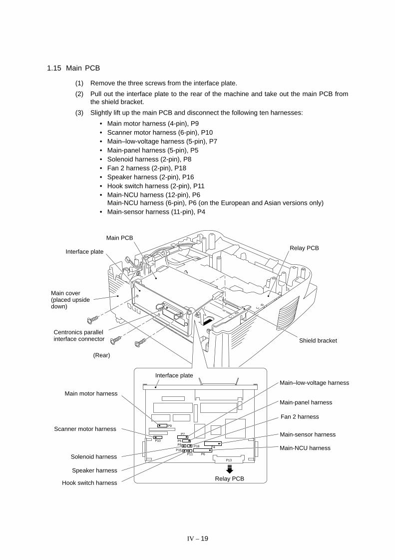
1.15 Main PCB
(1) Remove the three screws from the interface plate.
(2) Pull out the interface plate to the rear of the machine and take out the main PCB fromthe shield bracket.
(3) Slightly lift up the main PCB and disconnect the following ten harnesses:
• Main motor harness (4-pin), P9• Scanner motor harness (6-pin), P10• Main–low-voltage harness (5-pin), P7• Main-panel harness (5-pin), P5• Solenoid harness (2-pin), P8• Fan 2 harness (2-pin), P18• Speaker harness (2-pin), P16• Hook switch harness (2-pin), P11• Main-NCU harness (12-pin), P6
Main-NCU harness (6-pin), P6 (on the European and Asian versions only)• Main-sensor harness (11-pin), P4
P9
P10
P18
P7
P5P8
P16P6
P13
P11
P4
Main PCB
(Rear)
Main-sensor harness
Main-panel harness
Main–low-voltage harness
Main motor harness
Scanner motor harness
Solenoid harness
Speaker harness
Hook switch harness
Main-NCU harness
Interface plate
Relay PCB
Shield bracket
Main cover(placed upsidedown)
Interface plate
Centronics parallelinterface connector
Relay PCB
Fan 2 harness

IV – 20
Reassembling Notes
• When reinstalling the main PCB, make sure that the harnesses are routed on the maincover as illustrated in Section 1.23.
• For the MFC6550MC/7550MC/9500 which has a nickel-hydrogen battery on the mainPCB, be sure to remove the battery from the PCB when transporting the PCB. Failure todo so may result in a short circuit, overcurrent flow, and fire.
When installing the nickel-hydrogen battery on the main PCB, bring its edge into contactwith the surface of the PCB and attach it to the interface plate 5 mm inwards from theplate edge as shown below.
Nickel-hydrogen battery
Interface plate
5 mm Connector (P14)
Bring the battery edge intocontact with the PCB.
Main PCB
(MFC6550MC/7550MC/9500)
IV – 21
PC1
PC2
P3
P2
P4
P1
SW
1
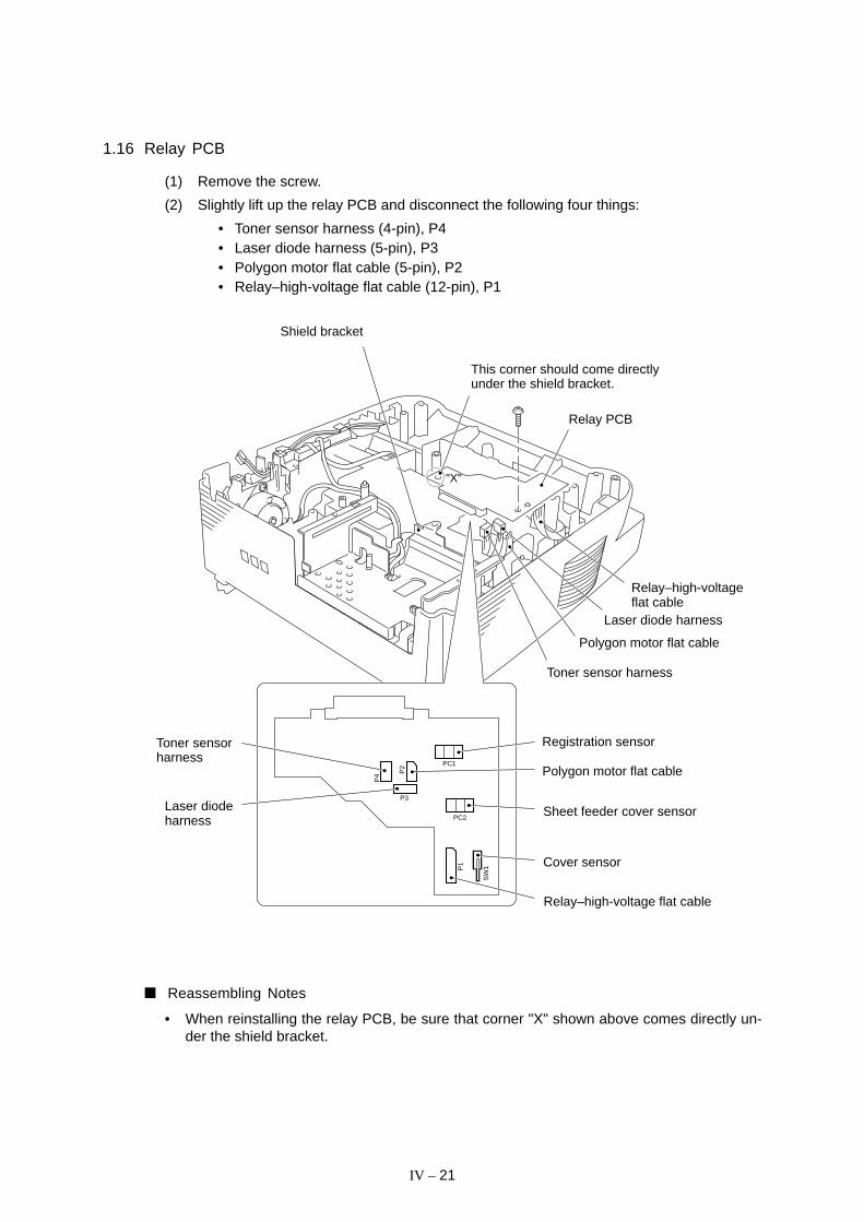
1.16 Relay PCB
(1) Remove the screw.
(2) Slightly lift up the relay PCB and disconnect the following four things:
• Toner sensor harness (4-pin), P4• Laser diode harness (5-pin), P3• Polygon motor flat cable (5-pin), P2• Relay–high-voltage flat cable (12-pin), P1
Registration sensor
Polygon motor flat cable
Sheet feeder cover sensor
Cover sensor
Relay–high-voltage flat cable
This corner should come directlyunder the shield bracket.
Relay PCB
Toner sensor harness
Toner sensorharness
Laser diodeharness
Shield bracket
Reassembling Notes
• When reinstalling the relay PCB, be sure that corner "X" shown above comes directly un-der the shield bracket.
"X"
Polygon motor flat cable
Laser diode harness
Relay–high-voltageflat cable
IV – 22
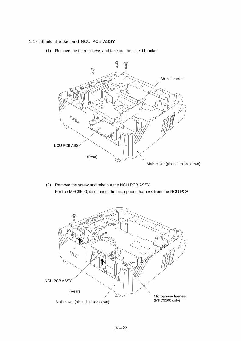
1.17 Shield Bracket and NCU PCB ASSY
(1) Remove the three screws and take out the shield bracket.
Shield bracket
Main cover (placed upside down)
NCU PCB ASSY
(Rear)
(2) Remove the screw and take out the NCU PCB ASSY.
For the MFC9500, disconnect the microphone harness from the NCU PCB.
NCU PCB ASSY
(Rear)
Main cover (placed upside down)
Microphone harness(MFC9500 only)

IV – 23
1.18 Gear Drive Unit
(1) Take out the heater harness (blue and brown wires) from the clamps provided on thegear drive unit.
(2) Take out the main motor harness, solenoid harness, and drum grounding harness fromthe clamp provided on the main cover.
Relay PCB
Main cover (placed upsidedown)
(Rear)
Clamp provided on the main cover
Main motor harness
Drum grounding harnessHeater harness(blue and brown wires)
Solenoid harness
Gear drive unit
Main motor
(3) Remove the three screws and take out the gear drive unit.
(Rear)
Gear drive unit
Solenoid harness (from the main PCB)
Drum grounding harness (from thehigh-voltage power supply PCB)
Main cover (placed upsidedown)
Main motor harness(from the main PCB)

IV – 24
(4) To replace the paper feed solenoid, solenoid lever or clutch release lever, remove thethree screws and take off the motor bracket.
(5) To remove the main motor from the bracket, remove two screws.
Reassembling Notes
• If the paper feed solenoid, solenoid lever, or clutch release lever has been removed, as-semble the removed parts as shown above.
Pull-in roller drivegear
Intermediate gear
Clutch gear
Solenoid spring
Paper feed solenoid
Planetarygear system
Gear 20/94Clutch release lever
Solenoid lever
Gear drive unit
Solenoid lever
Clutch release lever
Solenoid spring
Clutch spring
Main motor
Motor bracket

IV – 25
1.19 Duct Cover, Fan 2, and Speaker
(1) Unhook the three latches of the duct cover and lift it up. Take out the fan 2.
(2) Unhook the latch and lift up the speaker.
Fan 2
(Front)
Latch
Contrast adjuster
Duct cover
Latches
Speaker
Latch
Main cover (placed upside down)
Reassembling Notes
• After reinstalling the duct cover, make sure that the harnesses are routed as illustrated inSection 1.23.
• When setting the fan 2, be careful with the installation direction. The name plate shouldface outwards.

IV – 26
1.20 Sheet Feeder Cover Sensor Actuator, Registration Sensor Actuator, and CoverSensor Actuator
(1) Pull up the sheet feeder cover sensor actuator.
(2) Pull up the registration sensor actuator.
(3) Unhook the spring and take out the cover sensor actuator.
Cover sensoractuator
(Rear)
Main cover (placedupside down)Sheet feeder cover
sensor actuator
Registration sensoractuator

IV – 27
1.21 Microphone (MFC9500 only)
(1) Disconnect the microphone harness from the NCU PCB and remove the NCU PCBASSY. (Refer to Section 1.17.)
(2) Turn the equipment rightside up.
(3) Lift up the microphone from the main cover.
Main cover (placed rightside up)
Boss
Microphone
(Front)
Reassembling Notes
• Put the microphone back into place with either boss facing up.

IV – 28
1.22 Cleaning of High-voltage Contacts and Grounding Contacts
If any toner particles, paper dust or dirt are on the contacts, clean them out. This will ensurethat power flows correctly to enable printing.
1
2
7 For developerroller
6 For corona wire5 For grid
4 For cleanerroller
3 For transferroller
Grounding Contacts High-voltage Contacts
Drum groundingboard
Gear drive unit
2
1
2
1
3
4
57
6
3
4
5
6
7
High-voltagepower supplyPCB
Drum unit

IV – 29
1.23 Harness Routing
Relay PCB
Fan 2 harness
Main-sensorharness
Relay–high-voltage flatcable
Main-panelharness
Fan 1harness
Drumgroundingharness
Speakerharness
Solenoidharness
Hook switchharness
Heater harness
Main motorharness
Main–low-voltageharness
Low-voltagepower supplyPCBNCU PCBMain PCB
Main-NCUharness
High-voltagepower supplyPCB
Eraserharness
Laser diodeharness
Toner sensorharness
Polygon motorflat cable
(Front)
Scanner motorharness
Microphoneharness(MFC9500only)

IV – 30
2. LUBRICATION
Apply Molykote EM-30L to the lubrication points as illustrated below.
For points A, apply a bean-sized pinch of grease (12 mm3).
For points B, apply a rice-sized pinch of grease (6 mm3).
[ 1 ] Inner coverB
B
Control panel lock (leaf spring)
(Front)
Inner cover
Document ejectionroller ASSY
Document take-in roller ASSYSeparation roller ASSY
Scanner frame
(Front)
AA
B
B
AA
B
B
A
B
B
AA
A
A
AA
B
B
A
A
A
B
B
B
A
A
AA
AA
[ 2 ] Scanner frame ASSY
Document feed roller ASSY

CHAPTER V.
MAINTENANCE MODE

CONTENTS
1. ENTRY INTO THE MAINTENANCE MODE................................................... V-1
2. LIST OF MAINTENANCE-MODE FUNCTIONS ............................................ V-2
3. DETAILED DESCRIPTION OF MAINTENANCE-MODE FUNCTIONS ......... V-4
3.1 E2PROM Parameter Initialization ........................................................... V-4
3.2 Scanning Compensation Data Initialization ........................................... V-5
3.3 Printout of Scanning Compensation Data ............................................. V-6
3.4 ADF Performance Test .......................................................................... V-8
3.5 Test Pattern 1 ........................................................................................ V-9
3.6 Firmware Switch Setting and Printout ................................................... V-10
3.7 Operational Check of Control Panel PCB.............................................. V-47
3.8 Sensor Operational Check .................................................................... V-48
3.9 CCD Scanner Area Setting .................................................................... V-49
3.10 Equipment Error Code Indication .......................................................... V-49
3.11 Output of Transmission Log to the Line ................................................. V-50

V – 1
1. ENTRY INTO THE MAINTENANCE MODE
To make the facsimile equipment enter the maintenance mode, press the Function ,* , 2 , 8 , 6 , and 4 keys in this order.
Within 2 seconds
The equipment beeps for approx. 3 seconds and displays "MAINTENANCE" on the LCD, in-dicating that it is placed in the initial maintenance mode, a mode in which the equipment isready to accept entry from the keys.
To select one of the maintenance-mode functions listed in Section 2, enter the corresponding2-digit function code with the numerical keys on the control panel. (The details of each main-tenance-mode function are described in Section 3.)
NOTES: • Pressing the 9 key twice in the initial maintenance mode restores the equip-ment to the standby state.
• Pressing the Stop button after entering only one digit restores the equipmentto the initial maintenance mode.
• If an invalid function code is entered, the equipment resumes the initial mainte-nance mode.
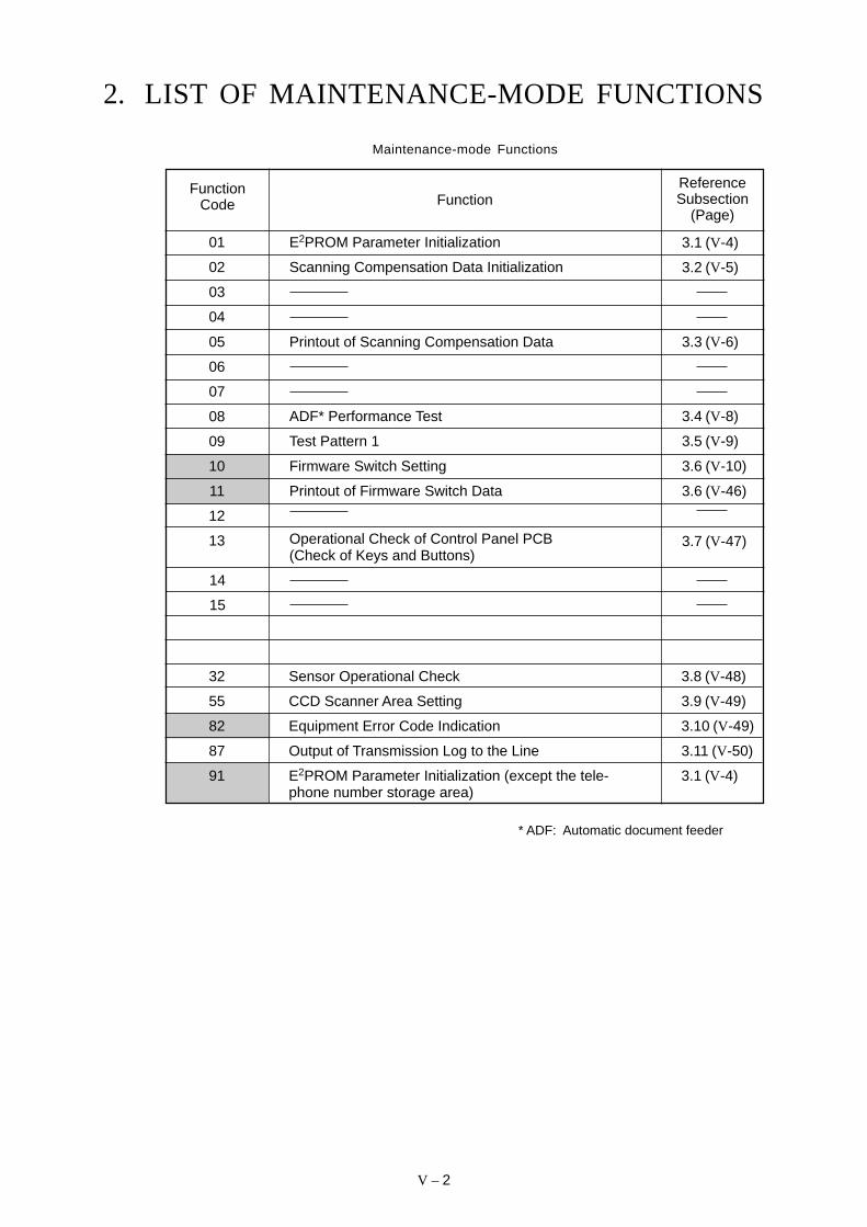
V – 2
ADF* Performance Test
Test Pattern 1
Firmware Switch Setting
Printout of Firmware Switch Data
2. LIST OF MAINTENANCE-MODE FUNCTIONS
Maintenance-mode Functions
Function
E2PROM Parameter Initialization
Scanning Compensation Data Initialization
ReferenceSubsection
(Page)
FunctionCode
01
02
03
04
05
06
07
08
09
10
11
12
13
3.1 (V-4)
3.2 (V-5)
Printout of Scanning Compensation Data 3.3 (V-6)
3.4 (V-8)
3.5 (V-9)
3.6 (V-10)
3.6 (V-46)
3.7 (V-47)
14
15
Operational Check of Control Panel PCB(Check of Keys and Buttons)
Sensor Operational Check
CCD Scanner Area Setting
Equipment Error Code Indication
Output of Transmission Log to the Line
E2PROM Parameter Initialization (except the tele-phone number storage area)
3.8 (V-48)
3.9 (V-49)
3.10 (V-49)
3.11 (V-50)
3.1 (V-4)
32
55
82
87
91
* ADF: Automatic document feeder
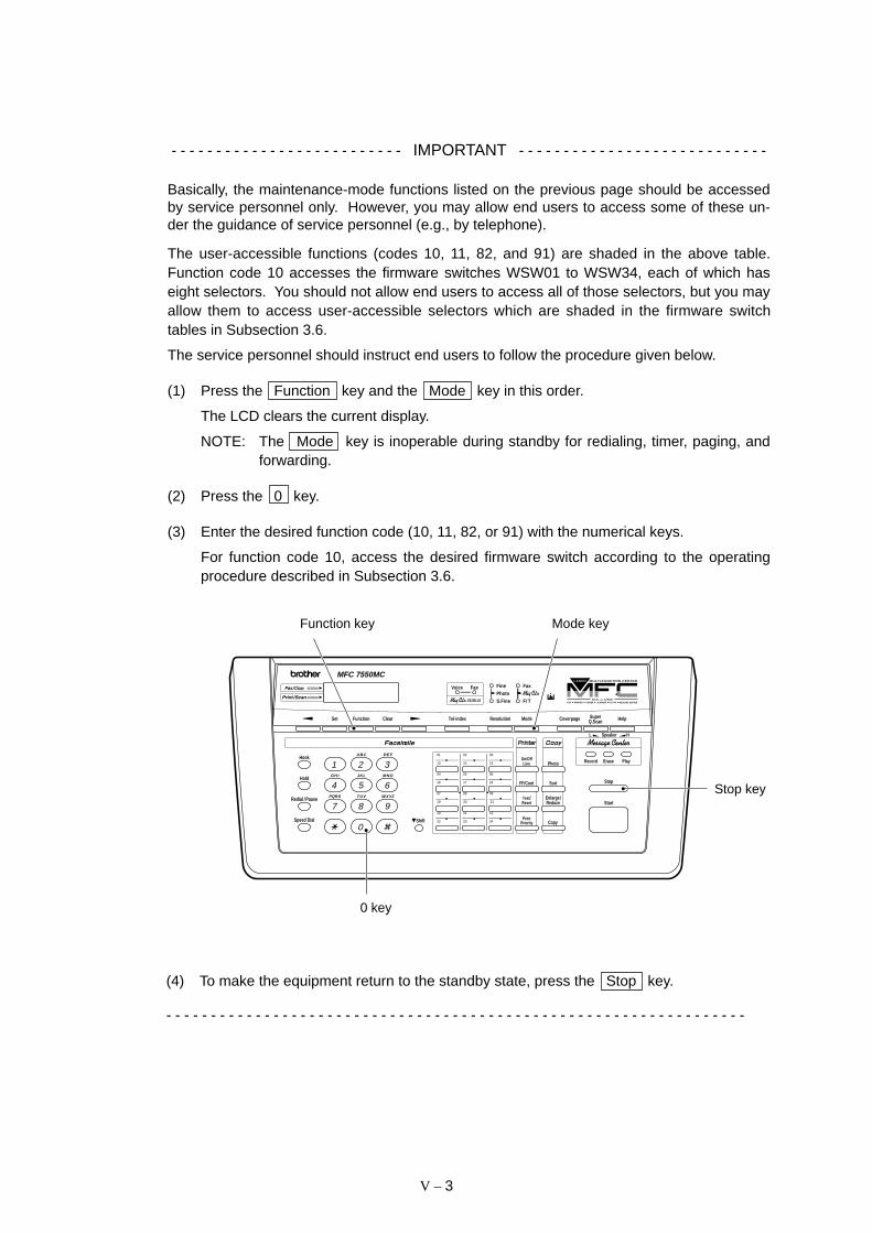
V – 3
- - - - - - - - - - - - - - - - - - - - - - - - - - IMPORTANT - - - - - - - - - - - - - - - - - - - - - - - - - - - -
Basically, the maintenance-mode functions listed on the previous page should be accessedby service personnel only. However, you may allow end users to access some of these un-der the guidance of service personnel (e.g., by telephone).
The user-accessible functions (codes 10, 11, 82, and 91) are shaded in the above table.Function code 10 accesses the firmware switches WSW01 to WSW34, each of which haseight selectors. You should not allow end users to access all of those selectors, but you mayallow them to access user-accessible selectors which are shaded in the firmware switchtables in Subsection 3.6.
The service personnel should instruct end users to follow the procedure given below.
(1) Press the Function key and the Mode key in this order.
The LCD clears the current display.
NOTE: The Mode key is inoperable during standby for redialing, timer, paging, andforwarding.
(2) Press the 0 key.
(3) Enter the desired function code (10, 11, 82, or 91) with the numerical keys.
For function code 10, access the desired firmware switch according to the operatingprocedure described in Subsection 3.6.
(4) To make the equipment return to the standby state, press the Stop key.
- - - - - - - - - - - - - - - - - - - - - - - - - - - - - - - - - - - - - - - - - - - - - - - - - - - - - - - - - - - - - - - - -
LineOn/Off
FF/Cont
PrintPriority
Test/
Copy
Photo
Reset
01 02 03
13 14 15
07 08 09
19 20 21
10 11 12
22 23 24
04 05 06
16 17 18
ReduceEnlarge/
Sort
Function Clear Tel-indexSet HelpSuperQ.ScanResolution Mode Coverpage
Stop
Start
Shift
Hook
Hold
Speed Dial
1
4
7
5 6
2 3
8 9
0
A BC DE F
GH I JKL MNO
PQRS TUV WXYZ
status
status
Redial / Pause
Record Erase
Speaker HL
Play
MFC 7550MC
FAX PRINTER COPIER SCANNER PC FAX MESSAGE CENTERSIX IN ONE
FinePhotoS.Fine
Fax
F/ T
Voice Fax
status
0 key
Function key Mode key
Stop key

V – 4
3 DETAILED DESCRIPTION OFMAINTENANCE-MODE FUNCTIONS
3.1 E2PROM Parameter Initialization
Function
The equipment initializes the parameters, user switches, and firmware switches registered inthe E2PROM, to the initial values. Entering the function code 01 initializes all of theE2PROM areas, but entering 91 does not initialize some areas, as listed below.
01Function code
Data item91
Maintenance-mode functionsUser switchesFirmware switchesRemote activation codeActivity reportDistinctive ringing patternsregistered (only for theU.S.A. versions)
Station ID dataCover page commentsOutside line number
Telephone function registrationOne-touch dialingSpeed dialingGroup dialing
Operating Procedure
(1) Press the 0 and 1 keys (or the 9 and 1 keys according to your need) in thisorder in the initial maintenance mode.
The "PARAMETER INIT" will appear on the LCD.
(2) Upon completion of parameter initialization, the equipment returns to the initial mainte-nance mode.
All of these willbe initialized.
These will notbe initialized.
These will beinitialized.
V – 5
3.2 Scanning Compensation Data Initialization
Function
The equipment scans the white pressure bar and writes the scanned compensation dataonto the E2PROM, so said data can be used for compensation of individual CCD propertiesin the scanning operation.
Operating Procedure
(1) Press the 0 and 2 keys in this order in the initial maintenance mode.
The “WHITE LEVEL INIT” will appear on the LCD.
(2) Upon completion of compensation data initialization, the equipment returns to the initialmaintenance mode.
NOTE: If any error occurs in the E2PROM white level data, the “SCANNER ERROR” or“CLEAN UP SCANNER” will appear on the LCD.

V – 6
3.3 Printout of Scanning Compensation Data
Function
The equipment prints out the white and black level data for scanning compensation.
Operating Procedure
Do not start this function merely after powering on the equipment but start it after carryingout a sequence of scanning operation. Unless the equipment has carried out any scanningoperation, this function cannot print out correct scanning compensation data. This is be-cause the equipment initializes white and black level data and takes in the scanning com-pensation reference data at the start of scanning operation.
(1) Press the 0 and 5 keys in this order in the initial maintenance mode.
The "WHITE LEVEL 1" will appear on the LCD.
(2) The equipment prints out the scanning compensation data list containing the following:
FAX3550/8000P/MFC4550 (200 dpi)
a) 2-value quantization white level data (208 bytes)
b) 2-value quantization black level data (1 byte)
c) Photo-mode white level data (208 bytes)
d) Photo-mode black level data (1 byte)
e) LED light intensity value, 2-value quantization LED light intensity value, and photo-mode LED light intensity value (3 bytes)
f) 2-value quantization A/D-high and photo-mode A/D-high values (2 bytes)
MFC6550MC/7550MC/9000/9500 (300 dpi)
a) 2-value quantization white level data (1664 bytes)
b) 2-value quantization black level data (1 byte)
c) Photo-mode white level data (1664 bytes)
d) Photo-mode black level data (1 byte)
e) LED light intensity value, 2-value quantization LED light intensity value, and photo-mode LED light intensity value (3 bytes)
f) 2-value quantization A/D-high, photo-mode A/D-high and A/D-low values (3 bytes)
(3) Upon completion of recording of the compensation data list, the equipment returns tothe initial maintenance mode.
NOTE: If any data is abnormal, its code will be printed in inline style, as shown on the nextpage.

V – 7
Scanning Compensation Data List (200 dpi)
V – 8
3.4 ADF Performance Test
Function
The equipment counts the documents fed by the automatic document feeder (ADF) and dis-plays the count on the LCD for checking the ADF performance.
Operating Procedure
(1) Set documents. (Allowable up to the ADF capacity.)
The "DOC. READY" will appear on the LCD.
(2) Press the 0 and 8 keys in this order.
The equipment
i) copies the 1st document and displays "P.01" on the LCD,
ii) feeds in and out the 2nd through 4th documents while counting without copyingthem as the LCD shows the corresponding count,
iii) copies the 5th document and displays "P.05" on the LCD,
iv) feeds in and out the 6th through 9th documents while counting without copyingthem as the LCD shows the corresponding count, and
v) copies the 10th document and displays "P.10" on the LCD.
(3) Upon completion of feeding in and out all of the documents, the final count appears onthe LCD.
(4) Press the Stop key to return the equipment to the initial maintenance mode.
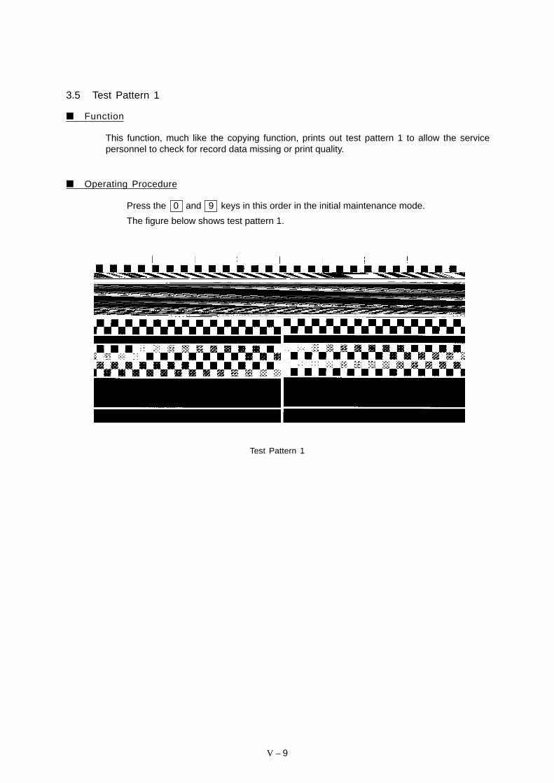
V – 9
3.5 Test Pattern 1
Function
This function, much like the copying function, prints out test pattern 1 to allow the servicepersonnel to check for record data missing or print quality.
Operating Procedure
Press the 0 and 9 keys in this order in the initial maintenance mode.
The figure below shows test pattern 1.
Test Pattern 1
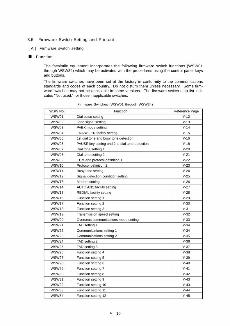
V – 10
WSW No. Function Reference Page
WSW01 Dial pulse setting V-12
WSW02 Tone signal setting V-13
WSW03 PABX mode setting V-14
WSW04 TRANSFER facility setting V-15
WSW05 1st dial tone and busy tone detection V-16
WSW06 PAUSE key setting and 2nd dial tone detection V-18
WSW07 Dial tone setting 1 V-20
WSW08 Dial tone setting 2 V-21
WSW09 ECM and protocol definition 1 V-22
WSW10 Protocol definition 2 V-23
WSW11 Busy tone setting V-24
WSW12 Signal detection condition setting V-25
WSW13 Modem setting V-26
WSW14 AUTO ANS facility setting V-27
WSW15 REDIAL facility setting V-28
WSW16 Function setting 1 V-29
WSW17 Function setting 2 V-30
WSW18 Function setting 3 V-31
WSW19 Transmission speed setting V-32
WSW20 Overseas communications mode setting V-33
WSW21 TAD setting 1 V-34
WSW22 Communications setting 1 V-34
WSW23 Communications setting 2 V-35
WSW24 TAD setting 2 V-36
WSW25 TAD setting 3 V-37
WSW26 Function setting 4 V-38
WSW27 Function setting 5 V-39
WSW28 Function setting 6 V-40
WSW29 Function setting 7 V-41
WSW30 Function setting 8 V-42
WSW31 Function setting 9 V-43
WSW32 Function setting 10 V-43
WSW33 Function setting 11 V-44
WSW34 Function setting 12 V-45
3.6 Firmware Switch Setting and Printout
[ A ] Firmware switch setting
Function
The facsimile equipment incorporates the following firmware switch functions (WSW01through WSW34) which may be activated with the procedures using the control panel keysand buttons.
The firmware switches have been set at the factory in conformity to the communicationsstandards and codes of each country. Do not disturb them unless necessary. Some firm-ware switches may not be applicable in some versions. The firmware switch data list indi-cates "Not used." for those inapplicable switches.
Firmware Switches (WSW01 through WSW34)
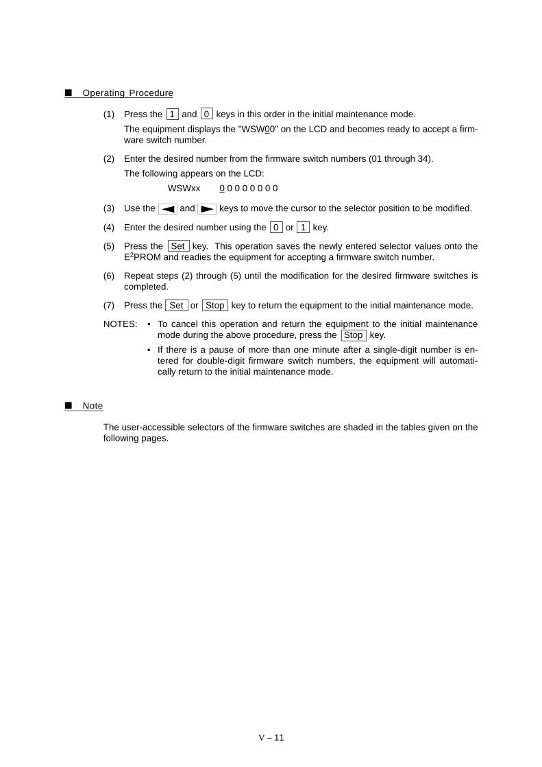
V – 11
Operating Procedure
(1) Press the 1 and 0 keys in this order in the initial maintenance mode.
The equipment displays the "WSW00" on the LCD and becomes ready to accept a firm-ware switch number.
(2) Enter the desired number from the firmware switch numbers (01 through 34).
The following appears on the LCD:
WSWxx 0 0 0 0 0 0 0 0
(3) Use the and keys to move the cursor to the selector position to be modified.
(4) Enter the desired number using the 0 or 1 key.
(5) Press the Set key. This operation saves the newly entered selector values onto theE2PROM and readies the equipment for accepting a firmware switch number.
(6) Repeat steps (2) through (5) until the modification for the desired firmware switches iscompleted.
(7) Press the Set or Stop key to return the equipment to the initial maintenance mode.
NOTES: • To cancel this operation and return the equipment to the initial maintenancemode during the above procedure, press the Stop key.
• If there is a pause of more than one minute after a single-digit number is en-tered for double-digit firmware switch numbers, the equipment will automati-cally return to the initial maintenance mode.
Note
The user-accessible selectors of the firmware switches are shaded in the tables given on thefollowing pages.
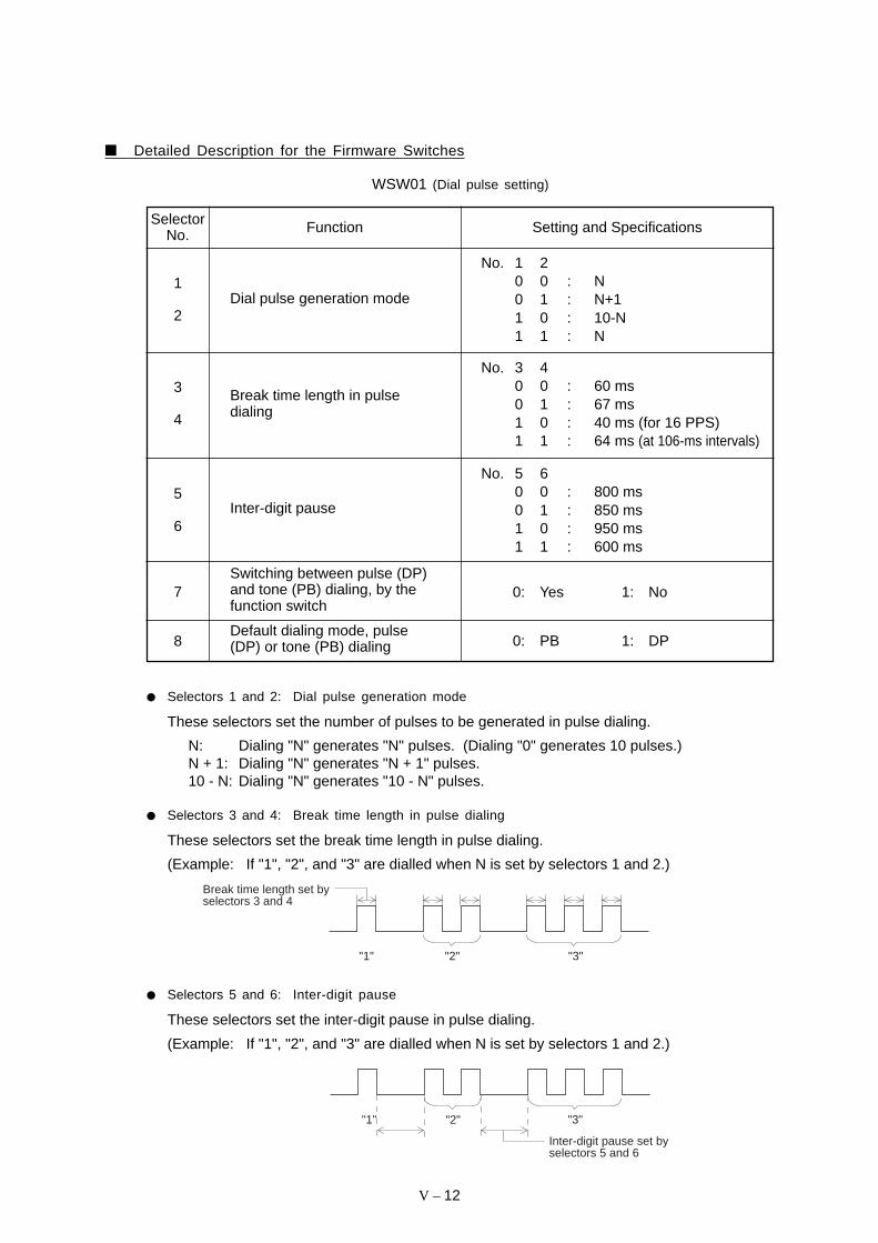
V – 12
Detailed Description for the Firmware Switches
WSW01 (Dial pulse setting)
FunctionSelectorNo. Setting and Specifications
8
1
2
3
4
5
6
Dial pulse generation mode
Inter-digit pause
Break time length in pulsedialing
No. 3 40 0 : 60 ms0 1 : 67 ms1 0 : 40 ms (for 16 PPS)1 1 : 64 ms (at 106-ms intervals)
No. 5 60 0 : 800 ms0 1 : 850 ms1 0 : 950 ms1 1 : 600 ms
Default dialing mode, pulse(DP) or tone (PB) dialing
Switching between pulse (DP)and tone (PB) dialing, by thefunction switch
7 0: Yes 1: No
No. 1 20 0 : N0 1 : N+11 0 : 10-N1 1 : N
0: PB 1: DP
Selectors 1 and 2: Dial pulse generation mode
These selectors set the number of pulses to be generated in pulse dialing.
N: Dialing "N" generates "N" pulses. (Dialing "0" generates 10 pulses.)N + 1: Dialing "N" generates "N + 1" pulses.10 - N: Dialing "N" generates "10 - N" pulses.
Selectors 3 and 4: Break time length in pulse dialing
These selectors set the break time length in pulse dialing.
(Example: If "1", "2", and "3" are dialled when N is set by selectors 1 and 2.)
"1" "2" "3"
Break time length set by selectors 3 and 4
Selectors 5 and 6: Inter-digit pause
These selectors set the inter-digit pause in pulse dialing.
(Example: If "1", "2", and "3" are dialled when N is set by selectors 1 and 2.)
"1" "2" "3"
Inter-digit pause set by selectors 5 and 6
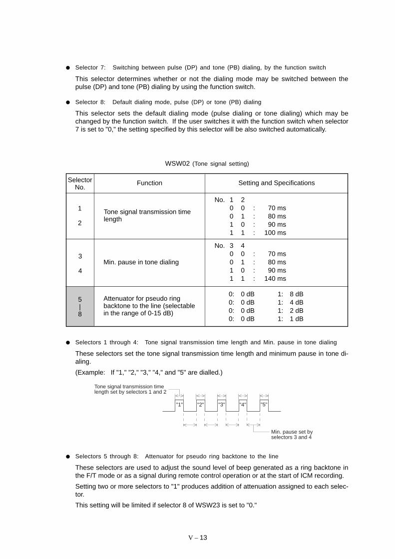
V – 13
Selector 7: Switching between pulse (DP) and tone (PB) dialing, by the function switch
This selector determines whether or not the dialing mode may be switched between thepulse (DP) and tone (PB) dialing by using the function switch.
Selector 8: Default dialing mode, pulse (DP) or tone (PB) dialing
This selector sets the default dialing mode (pulse dialing or tone dialing) which may bechanged by the function switch. If the user switches it with the function switch when selector7 is set to "0," the setting specified by this selector will be also switched automatically.
WSW02 (Tone signal setting)
Function Setting and SpecificationsSelectorNo.
1
2
3
4
5|8
Tone signal transmission timelength
Min. pause in tone dialing
No. 1 20 0 : 70 ms0 1 : 80 ms1 0 : 90 ms1 1 : 100 ms
No. 3 40 0 : 70 ms0 1 : 80 ms1 0 : 90 ms1 1 : 140 ms
0: 0 dB 1: 8 dB0: 0 dB 1: 4 dB0: 0 dB 1: 2 dB0: 0 dB 1: 1 dB
Selectors 1 through 4: Tone signal transmission time length and Min. pause in tone dialing
These selectors set the tone signal transmission time length and minimum pause in tone di-aling.
(Example: If "1," "2," "3," "4," and "5" are dialled.)
"1" "2" "3" "4" "5"
Min. pause set by selectors 3 and 4
Tone signal transmission time length set by selectors 1 and 2
Selectors 5 through 8: Attenuator for pseudo ring backtone to the line
These selectors are used to adjust the sound level of beep generated as a ring backtone inthe F/T mode or as a signal during remote control operation or at the start of ICM recording.
Setting two or more selectors to "1" produces addition of attenuation assigned to each selec-tor.
This setting will be limited if selector 8 of WSW23 is set to "0."
Attenuator for pseudo ringbacktone to the line (selectablein the range of 0-15 dB)

V – 14
WSW03 (PABX* mode setting)
FunctionSelectorNo.
No. 2 3 40 0 0 : 50 ms0 0 1 : 210 ms0 1 0 : 500 ms0 1 1 : 800 ms1 0 0 : 900 ms1 0 1 : 1.5 sec.1 1 0 : 2.0 sec.1 1 1 : 2.5 sec.
1
Setting and Specifications
2
|
4
Min. detection time length ofPABX dial tone, required forstarting dialing
Not used.
5 Not used.
8
6
7Dial tone detection in PABX
No. 6 70 0 : No detection
(3.5 sec. WAIT)0 1 : No detection
(5 sec. WAIT)1 0 : No detection
(7 sec. WAIT)1 1 : Detection
(Frequency only)
"R" key function 0: 1st dial tone 1: No 1st dialdetection add tone detection
* PABX: Private automatic branch exchange
NOTE: The WSW03 is not applicable in those countries where no PABX is supported, e.g.,U.S.A.
Selectors 2 through 4: Min. detection time length of PABX dial tone, required for startingdialing
Upon detection of the PABX dial tone for the time length set by these selectors, the equip-ment starts dialing.
These selectors are effective only when both selectors 6 and 7 are set to "1" (Detection).
Selectors 6 and 7: Dial tone detection in PABX
These selectors activate or deactivate the dial tone detection function which detects a dialtone when a line is connected to the PABX.
Setting both of these selectors to "1" activates the dial tone detection function so that theequipment starts dialing upon detection of a dial tone when a line is connected.
Other setting combinations deactivate the dial tone detection function so that the equipmentstarts dialing after the specified WAIT (3.5, 5.0, or 7.0 sec.) without detection of a dial tonewhen a line is connected.
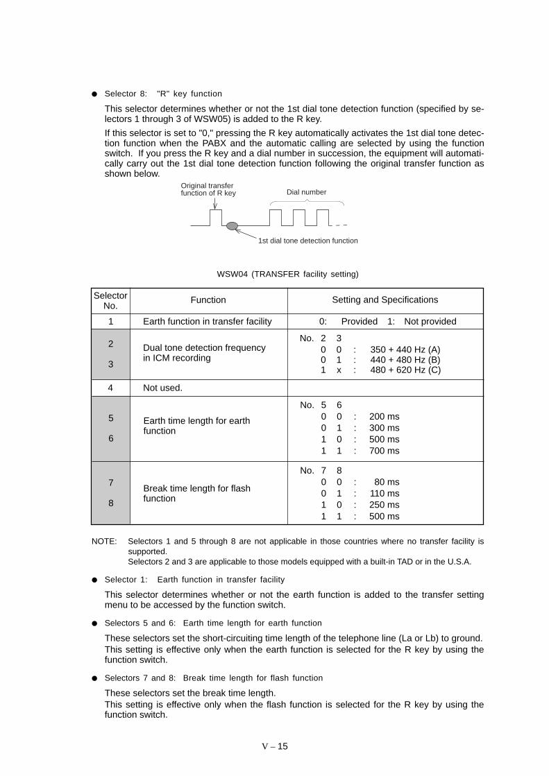
V – 15
Selector 8: "R" key function
This selector determines whether or not the 1st dial tone detection function (specified by se-lectors 1 through 3 of WSW05) is added to the R key.
If this selector is set to "0," pressing the R key automatically activates the 1st dial tone detec-tion function when the PABX and the automatic calling are selected by using the functionswitch. If you press the R key and a dial number in succession, the equipment will automati-cally carry out the 1st dial tone detection function following the original transfer function asshown below.
Dial numberOriginal transfer function of R key
1st dial tone detection function
WSW04 (TRANSFER facility setting)
FunctionSelectorNo.
Setting and Specifications
1 Earth function in transfer facility 0: Provided 1: Not provided
2
3
No. 2 30 0 : 350 + 440 Hz (A)0 1 : 440 + 480 Hz (B)1 x : 480 + 620 Hz (C)
Dual tone detection frequencyin ICM recording
Not used.4
5
6
Break time length for flashfunction
7
8
No. 7 80 0 : 80 ms0 1 : 110 ms1 0 : 250 ms1 1 : 500 ms
No. 5 60 0 : 200 ms0 1 : 300 ms1 0 : 500 ms1 1 : 700 ms
Earth time length for earthfunction
NOTE: Selectors 1 and 5 through 8 are not applicable in those countries where no transfer facility issupported.Selectors 2 and 3 are applicable to those models equipped with a built-in TAD or in the U.S.A.
Selector 1: Earth function in transfer facility
This selector determines whether or not the earth function is added to the transfer settingmenu to be accessed by the function switch.
Selectors 5 and 6: Earth time length for earth function
These selectors set the short-circuiting time length of the telephone line (La or Lb) to ground.This setting is effective only when the earth function is selected for the R key by using thefunction switch.
Selectors 7 and 8: Break time length for flash function
These selectors set the break time length.This setting is effective only when the flash function is selected for the R key by using thefunction switch.

V – 16
WSW05 (1st dial tone and busy tone detection)
FunctionSelectorNo. Setting and Specifications
Max. pause time allowable forremote ID code detection
Busy tone detection in auto-matic receiving mode
1st dial tone detection
1
|
3
4 0: 2 seconds 1: 1 second
Busy tone detection in auto-matic sending mode
No. 1 2 30 0 0 : 3.5 sec. WAIT0 0 1 : 7.0 sec. WAIT0 1 0 : 10.5 sec. WAIT0 1 1 : 14.0 sec. WAIT1 0 0 : 17.5 sec. WAIT1 0 1 : 21.0 sec. WAIT1 1 0 : 24.5 sec. WAIT1 1 1 : Detection (Without WAIT)
No. 5 60 0 : No detection0 1 : Detection only
after dialing1 0 : No detection1 1 : Detection before
and after dialing
0: Yes 1: No7
5
6
DTMF detection time
NOTE: Selectors 5 through 7 are not applicable in those countries where no busy tone detec-tion is supported, e.g., U.S.A.
Selectors 1 through 3: 1st dial tone detection
These selectors activate or deactivate the 1st dial tone detection function which detects the1st dial tone issued from the PSTN when a line is connected to the PSTN.
Setting all of these selectors to "1" activates the dial tone detection function so that theequipment starts dialing upon detection of a dial tone when a line is connected. (However, inthose countries which support no dial tone detection function, e.g. in the U.S.A., settingthese selectors to "1" makes the equipment start dialing after a WAIT of 3.5 seconds.) Forthe detecting conditions of the 1st dial tone, refer to WSW07 and WSW08.
Other setting combinations deactivate the dial tone detection function so that the equipmentstarts dialing after the specified WAIT (3.5, 7.0, 10.5, 14.0, 17.5, 21.0, or 24.5 seconds) with-out detection of a dial tone when a line is connected to the PSTN.
Selector 4: Max. pause time allowable for remote ID code detection
This selector sets the maximum pause time allowable for detecting the second digit of a re-mote ID code after detection of the first digit in remote reception.
If selector 4 is set to "0" (2 seconds), for instance, only a remote ID code whose second digitis detected within 2 seconds after detection of the first digit will become effective so as toactivate the remote function.
0: 40 ms min. 1: 100 ms min.8

V – 17
Selectors 5 and 6: Busy tone detection in automatic sending mode
These selectors determine whether or not the equipment automatically disconnects a lineupon detection of a busy tone in automatic sending mode.
Setting selector 6 to "0" ignores a busy tone so that the equipment does not disconnect theline.
Setting selectors 5 and 6 to "0" and "1," respectively, makes the equipment detect a busytone only after dialing and disconnect the line.
Setting both of selectors 5 and 6 to "1" makes the equipment detect a busy tone before andafter dialing and then disconnect the line.
Selector 7: Busy tone detection in automatic receiving mode
This selector determines whether or not the equipment automatically disconnects a line upondetection of a busy tone in automatic receiving mode
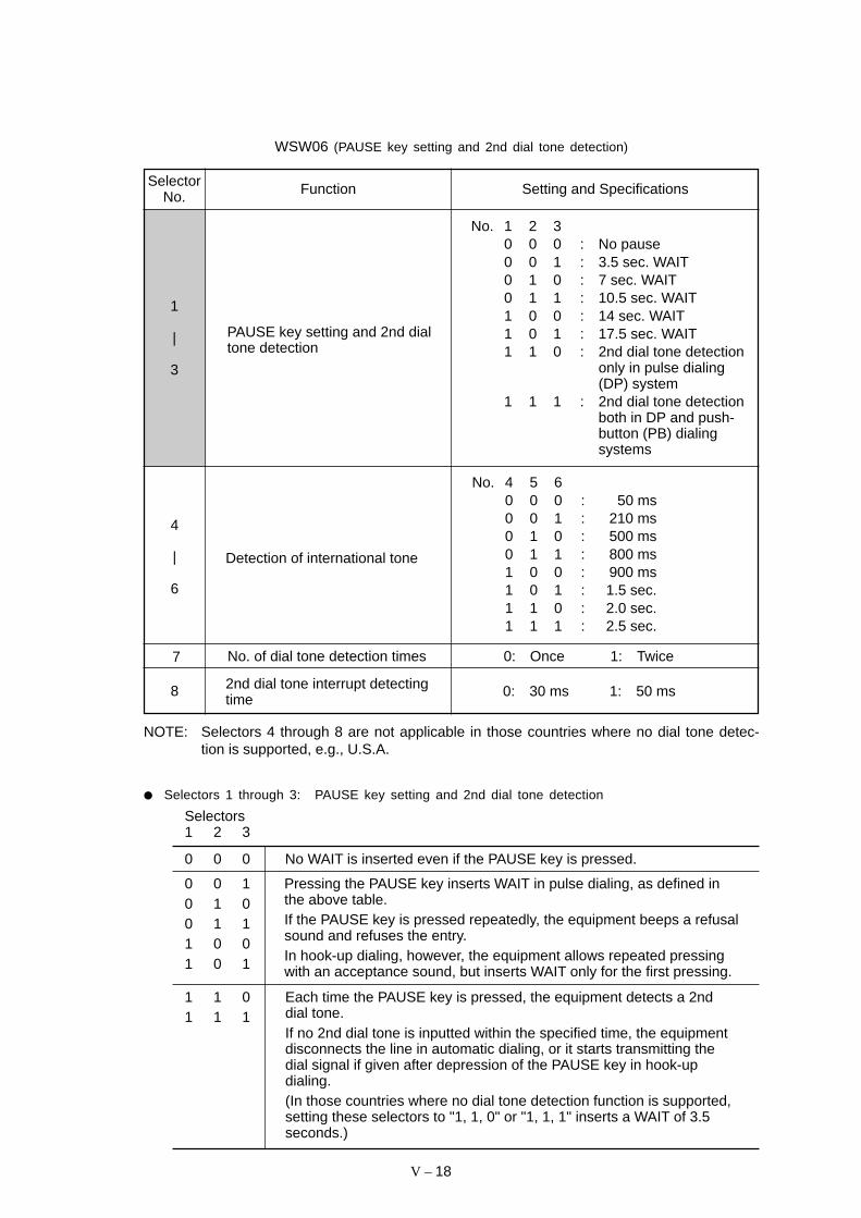
V – 18
WSW06 (PAUSE key setting and 2nd dial tone detection)
FunctionSelectorNo. Setting and Specifications
PAUSE key setting and 2nd dialtone detection
2nd dial tone interrupt detectingtime
1
|
3
4
|
6
8
7 No. of dial tone detection times 0: Once 1: Twice
0: 30 ms 1: 50 ms
Detection of international tone
No. 1 2 30 0 0 : No pause0 0 1 : 3.5 sec. WAIT0 1 0 : 7 sec. WAIT0 1 1 : 10.5 sec. WAIT1 0 0 : 14 sec. WAIT1 0 1 : 17.5 sec. WAIT1 1 0 : 2nd dial tone detection
only in pulse dialing(DP) system
1 1 1 : 2nd dial tone detectionboth in DP and push-button (PB) dialingsystems
No. 4 5 60 0 0 : 50 ms0 0 1 : 210 ms0 1 0 : 500 ms0 1 1 : 800 ms1 0 0 : 900 ms1 0 1 : 1.5 sec.1 1 0 : 2.0 sec.1 1 1 : 2.5 sec.
NOTE: Selectors 4 through 8 are not applicable in those countries where no dial tone detec-tion is supported, e.g., U.S.A.
Selectors 1 through 3: PAUSE key setting and 2nd dial tone detection
Selectors1 2 3
1 1 01 1 1
Each time the PAUSE key is pressed, the equipment detects a 2nddial tone.If no 2nd dial tone is inputted within the specified time, the equipmentdisconnects the line in automatic dialing, or it starts transmitting thedial signal if given after depression of the PAUSE key in hook-updialing.(In those countries where no dial tone detection function is supported,setting these selectors to "1, 1, 0" or "1, 1, 1" inserts a WAIT of 3.5seconds.)
0 0 10 1 00 1 11 0 01 0 1
Pressing the PAUSE key inserts WAIT in pulse dialing, as defined inthe above table.If the PAUSE key is pressed repeatedly, the equipment beeps a refusalsound and refuses the entry.In hook-up dialing, however, the equipment allows repeated pressingwith an acceptance sound, but inserts WAIT only for the first pressing.
0 0 0 No WAIT is inserted even if the PAUSE key is pressed.

V – 19
Selectors 4 through 6: Detection of international tone
Upon detection of the 2nd dial tone for the time length specified by these selectors, theequipment starts dialing.
This setting is effective only when the 2nd dial tone detection function is activated by selec-tors 1 through 3 (Setting 1, 1, 0 or 1, 1, 1).
This function does not apply in those countries where no dial tone detection function is sup-ported.
Selector 7: No. of dial tone detection times
This selector sets the number of dial tone detection times required for starting dialing.
Selector 8: 2nd dial tone interrupt detecting time
This selector sets the allowable time length of an interrupt which should not be interpreted asan interrupt in the 2nd tone dialing.
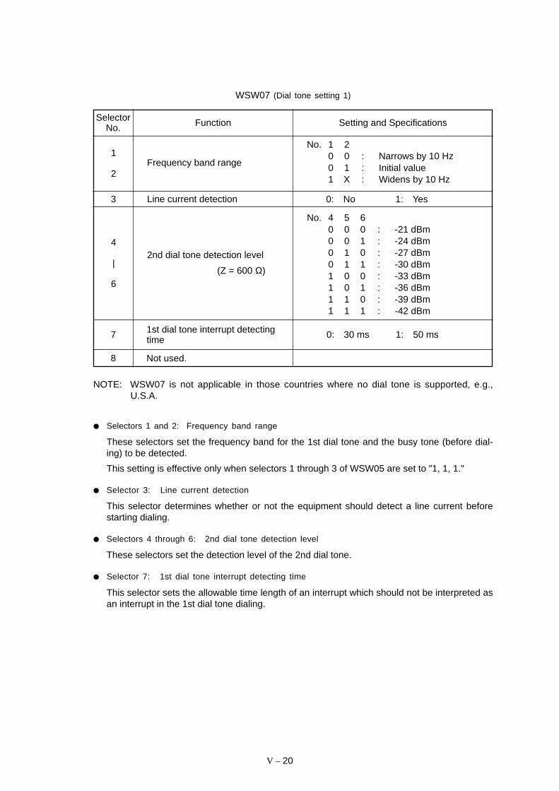
V – 20
WSW07 (Dial tone setting 1)
FunctionSelectorNo. Setting and Specifications
No. 4 5 60 0 0 : -21 dBm0 0 1 : -24 dBm0 1 0 : -27 dBm0 1 1 : -30 dBm1 0 0 : -33 dBm1 0 1 : -36 dBm1 1 0 : -39 dBm1 1 1 : -42 dBm
NOTE: WSW07 is not applicable in those countries where no dial tone is supported, e.g.,U.S.A.
Selectors 1 and 2: Frequency band range
These selectors set the frequency band for the 1st dial tone and the busy tone (before dial-ing) to be detected.
This setting is effective only when selectors 1 through 3 of WSW05 are set to "1, 1, 1."
Selector 3: Line current detection
This selector determines whether or not the equipment should detect a line current beforestarting dialing.
Selectors 4 through 6: 2nd dial tone detection level
These selectors set the detection level of the 2nd dial tone.
Selector 7: 1st dial tone interrupt detecting time
This selector sets the allowable time length of an interrupt which should not be interpreted asan interrupt in the 1st dial tone dialing.
1
2
4
|
6
7
8 Not used.
1st dial tone interrupt detectingtime
2nd dial tone detection level
(Z = 600 Ω)
Frequency band range
3 Line current detection 0: No 1: Yes
No. 1 20 0 : Narrows by 10 Hz0 1 : Initial value1 X : Widens by 10 Hz
0: 30 ms 1: 50 ms

V – 21
WSW08 (Dial tone setting 2)
FunctionSelectorNo. Setting and Specifications
1
|
3
1st dial tone detection timelength
No. 1 2 30 0 0 : 50 ms0 0 1 : 210 ms0 1 0 : 500 ms0 1 1 : 800 ms1 0 0 : 900 ms1 0 1 : 1.5 sec.1 1 0 : 2.0 sec.1 1 1 : 2.5 sec.
No. 4 50 0 : 10 sec.0 1 : 20 sec.1 0 : 6 sec. (in the U.S.A. versions)
15 sec. (in other versions)1 1 : 30 sec.
Time-out length for 1st and 2nddial tone detection
4
5
No. 6 7 80 0 0 : -21 dBm0 0 1 : -24 dBm0 1 0 : -27 dBm0 1 1 : -30 dBm1 0 0 : -33 dBm1 0 1 : -36 dBm1 1 0 : -39 dBm1 1 1 : -42 dBm
6
|
8
Detection level of 1st dial toneand busy tone before dialing
(Z = 600 Ω)
NOTE: WSW08 is not applicable in those countries where no dial tone detection is supported,e.g., U.S.A.
Selectors 1 through 3: 1st dial tone detection time length
Upon detection of the 1st dial tone for the time length set by these selectors, the equipmentstarts dialing.
This setting is effective only when selectors 1 through 3 of WSW05 are set to "1, 1, 1."
Selectors 4 and 5: Time-out length for 1st and 2nd dial tone detection
These selectors set the time-out length for the 1st and 2nd dial tone detection so that theequipment waits dial tone input for the specified time length and disconnects itself from theline when no dial tone is inputted.
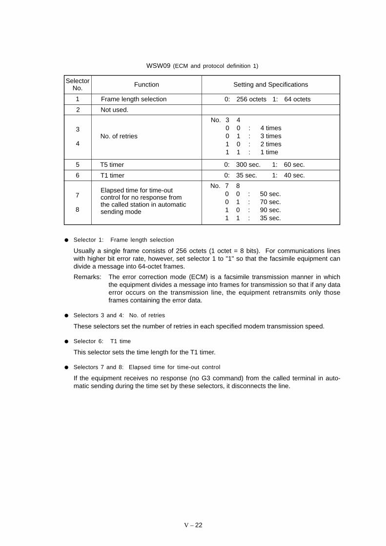
V – 22
WSW09 (ECM and protocol definition 1)
FunctionSelectorNo. Setting and Specifications
1 0: 256 octets 1: 64 octets
2 Not used.
Frame length selection
3
4No. of retries
No. 3 40 0 : 4 times0 1 : 3 times1 0 : 2 times1 1 : 1 time
Elapsed time for time-outcontrol for no response fromthe called station in automaticsending mode
No. 7 80 0 : 50 sec.0 1 : 70 sec.1 0 : 90 sec.1 1 : 35 sec.
7
8
6 T1 timer 0: 35 sec. 1: 40 sec.
5 T5 timer 0: 300 sec. 1: 60 sec.
Selector 1: Frame length selection
Usually a single frame consists of 256 octets (1 octet = 8 bits). For communications lineswith higher bit error rate, however, set selector 1 to "1" so that the facsimile equipment candivide a message into 64-octet frames.
Remarks: The error correction mode (ECM) is a facsimile transmission manner in whichthe equipment divides a message into frames for transmission so that if any dataerror occurs on the transmission line, the equipment retransmits only thoseframes containing the error data.
Selectors 3 and 4: No. of retries
These selectors set the number of retries in each specified modem transmission speed.
Selector 6: T1 time
This selector sets the time length for the T1 timer.
Selectors 7 and 8: Elapsed time for time-out control
If the equipment receives no response (no G3 command) from the called terminal in auto-matic sending during the time set by these selectors, it disconnects the line.
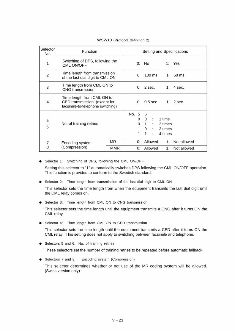
V – 23
WSW10 (Protocol definition 2)
FunctionSelectorNo. Setting and Specifications
Switching of DPS, following theCML ON/OFF1
Time length from transmissionof the last dial digit to CML ON
Time length from CML ON toCNG transmission3
Time length from CML ON toCED transmission (except forfacsimile-to-telephone switching)
2
0: No 1: Yes
0: 100 ms 1: 50 ms
0: 2 sec. 1: 4 sec.
4 0: 0.5 sec. 1: 2 sec.
5
6No. of training retries
No. 5 60 0 : 1 time0 1 : 2 times1 0 : 3 times1 1 : 4 times
78
Encoding system(Compression)
0: Allowed 1: Not allowed
0: Allowed 1: Not allowed
MR
MMR
Selector 1: Switching of DPS, following the CML ON/OFF
Setting this selector to "1" automatically switches DPS following the CML ON/OFF operation.This function is provided to conform to the Swedish standard.
Selector 2: Time length from transmission of the last dial digit to CML ON
This selector sets the time length from when the equipment transmits the last dial digit untilthe CML relay comes on.
Selector 3: Time length from CML ON to CNG transmission
This selector sets the time length until the equipment transmits a CNG after it turns ON theCML relay.
Selector 4: Time length from CML ON to CED transmission
This selector sets the time length until the equipment transmits a CED after it turns ON theCML relay. This setting does not apply to switching between facsimile and telephone.
Selectors 5 and 6: No. of training retries
These selectors set the number of training retries to be repeated before automatic fallback.
Selectors 7 and 8: Encoding system (Compression)
This selector determines whether or not use of the MR coding system will be allowed.(Swiss version only)

V – 24
WSW11 (Busy tone setting)
FunctionSelectorNo. Setting and Specifications
1
2Frequency band range
No. 1 20 0 : Narrows by 10 Hz0 1 : Initial value1 x : Widens by 10 Hz
3 Not used.
4
5
6
7
8
ON/OFF time length ranges
(More than one setting allowed)
1: 400-600/400-600 ms
1: 175-440/175-440 ms
1: 700-800/700-800 ms
1: 110-410/320-550 ms
1: 100-660/100-660 ms
NOTE: WSW11 is not applicable in those countries where no busy tone detection is supported,e.g., U.S.A.
The setting of WSW11 is effective only when selectors 5 and 6 of WSW05 are set to "0,1" or "1, 1" (Busy tone detection).
Selectors 1 and 2: Frequency band range
These selectors set the frequency band for busy tone to be detected.
Selectors 4 through 8: ON/OFF time length ranges
These selectors set the ON and OFF time length ranges for busy tone to be detected. Ifmore than one selector is set to "1," the ranges become wider. For example, if selectors 4and 5 are set to "1," the ON and OFF time length ranges are from 175 to 600 ms.
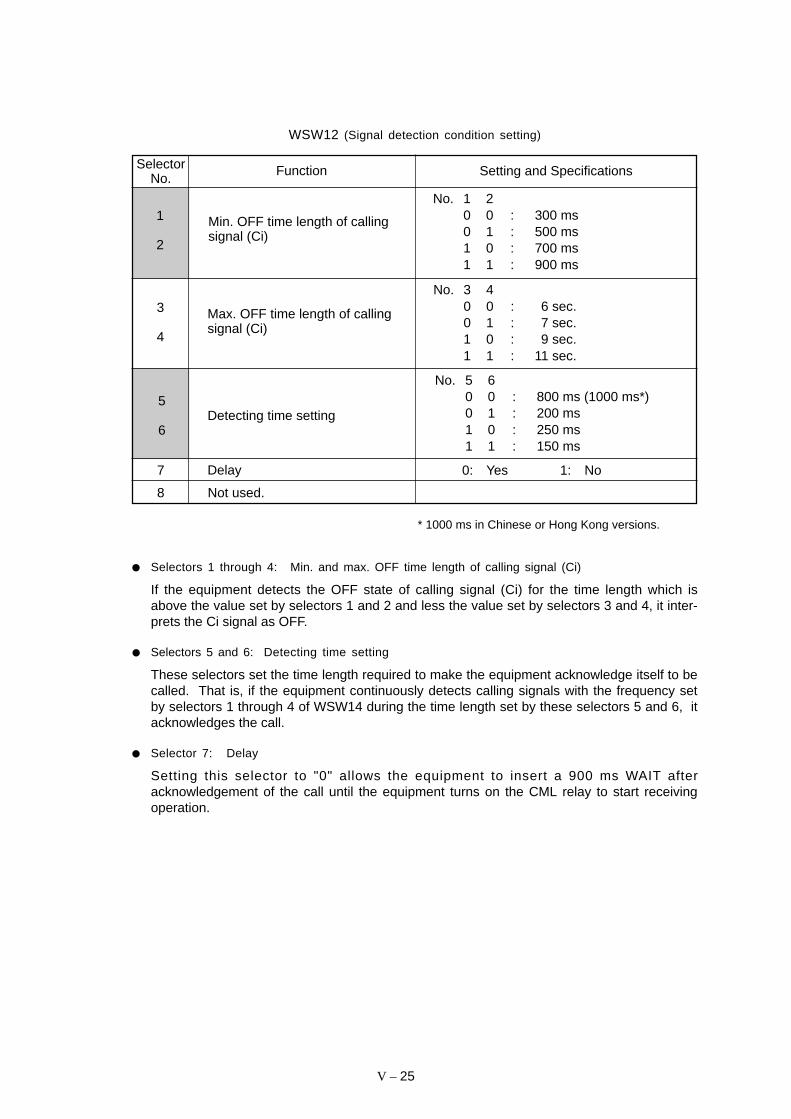
V – 25
WSW12 (Signal detection condition setting)
SelectorNo.
Function Setting and Specifications
7
8
Delay
Not used.
5
6
No. 5 60 0 : 800 ms (1000 ms*)0 1 : 200 ms1 0 : 250 ms1 1 : 150 ms
Detecting time setting
3
4
Max. OFF time length of callingsignal (Ci)
No. 3 40 0 : 6 sec.0 1 : 7 sec.1 0 : 9 sec.1 1 : 11 sec.
1
2
Min. OFF time length of callingsignal (Ci)
No. 1 20 0 : 300 ms0 1 : 500 ms1 0 : 700 ms1 1 : 900 ms
* 1000 ms in Chinese or Hong Kong versions.
Selectors 1 through 4: Min. and max. OFF time length of calling signal (Ci)
If the equipment detects the OFF state of calling signal (Ci) for the time length which isabove the value set by selectors 1 and 2 and less the value set by selectors 3 and 4, it inter-prets the Ci signal as OFF.
Selectors 5 and 6: Detecting time setting
These selectors set the time length required to make the equipment acknowledge itself to becalled. That is, if the equipment continuously detects calling signals with the frequency setby selectors 1 through 4 of WSW14 during the time length set by these selectors 5 and 6, itacknowledges the call.
Selector 7: Delay
Setting this selector to "0" allows the equipment to insert a 900 ms WAIT afteracknowledgement of the call until the equipment turns on the CML relay to start receivingoperation.
0: Yes 1: No

V – 26
WSW13 (Modem setting)
FunctionSelectorNo. Setting and Specifications
5|8
Modem attenuator
3
4Reception level (Z = 600 Ω)
1
2Cable equalizer
No. 1 20 0 : 0 km0 1 : 1.8 km1 0 : 3.6 km1 1 : 5.6 km
No. 3 40 0 : -43 dBm0 1 : -47 dBm1 0 : -49 dBm1 1 : -51 dBm
0: 0 dB 1: 8 dB0: 0 dB 1: 4 dB0: 0 dB 1: 2 dB0: 0 dB 1: 1 dB
The modem should be adjusted according to the user’s line conditions.
Selectors 1 and 2: Cable equalizer
These selectors are used to improve the pass-band characteristics of analogue signals on aline. (Attenuation in the high-band frequency is greater than in the low-band frequency.)
Set these selectors according to the distance from the telephone switchboard to the facsimileequipment.
Selectors 3 and 4: Reception level
These selectors set the optimum receive signal level.
Selectors 5 through 8: Modem attenuator
These selectors are used to adjust the transmitting level of the modem when the receptionlevel at the remote station is improper due to line loss.
Setting two or more selectors to "1" produces addition of attenuation assigned to each selec-tor.
This setting will be limited if selector 8 of WSW23 is set to "0."

V – 27
WSW14 (AUTO ANS facility setting)
FunctionSelectorNo. Setting and Specifications
1
2
No. 5 6 7 80 0 0 0 : Fixed to once0 0 0 1 : Fixed to 2 times0 0 1 0 : Fixed to 3 times0 0 1 1 : Fixed to 4 times0 1 0 0 : 1 to 2 times0 1 0 1 : 1 to 3 times0 1 1 0 : 1 to 4 times0 1 1 1 : 1 to 5 times1 0 0 0 : 2 to 3 times1 0 0 1 : 2 to 4 times1 0 1 0 : 2 to 5 times1 0 1 1 : 2 to 6 times1 1 0 0 : 1 to 10 times1 1 0 1 : 2 to 10 times1 1 1 0 : 3 to 5 times1 1 1 1 : 4 to 10 times
3
4
Frequency band selection
(Upper limit)
No. 3 40 0 : 30 Hz0 1 : 55 Hz1 0 : 70 Hz1 1 : 70 Hz
Frequency band selection
(Lower limit)
No. 1 20 0 : 13 Hz0 1 : 15 Hz1 0 : 23 Hz1 1 : 20 Hz
Selectors 1 through 4: Frequency band selection
These selectors are used to select the frequency band of calling signals for activating theAUTO ANS facility.
Selectors 5 through 8: No. of rings in AUTO ANS mode
These selectors set the number of rings to initiate the AUTO ANS facility.
5
|
8
No. of rings in AUTO ANSmode
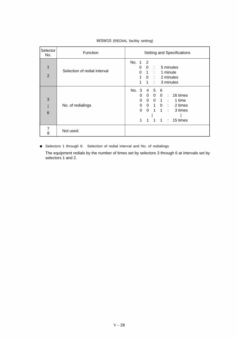
V – 28
WSW15 (REDIAL facility setting)
FunctionSelectorNo. Setting and Specifications
1
2Selection of redial interval
No. 1 20 0 : 5 minutes0 1 : 1 minute1 0 : 2 minutes1 1 : 3 minutes
No. 3 4 5 60 0 0 0 : 16 times0 0 0 1 : 1 time0 0 1 0 : 2 times0 0 1 1 : 3 times
| |1 1 1 1 : 15 times
78 Not used.
Selectors 1 through 6: Selection of redial interval and No. of redialings
The equipment redials by the number of times set by selectors 3 through 6 at intervals set byselectors 1 and 2.
3
|
6
No. of redialings

V – 29
WSW16 (Function setting 1)
FunctionSelectorNo.
Setting and Specifications
1 Not used.
2 CCITT superfine recommendation 0: OFF 1: ON
45
3 Remote reception
0: Only from the 1: From allconnected telephonesexternal connectedtelephone
6 Exclusive line mode 0: OFF 1: ON
7 Max. document length limitation 0: 400 cm 1: 90 cm
Not used.8
Not used.
Selector 2: CCITT superfine recommendation
If this selector is set to "1," the equipment communicates in CCITT recommended superfinemode (15.4 lines/mm). If it is set to "0," it communicates in native superfine mode.
Selector 3: Remote reception
Setting this selector to "0" allows the facsimile equipment to receive data from the directlyconnected external telephone only. Setting it to "1" allows the equipment to receive datafrom all telephones sharing a modular wall socket with the equipment, as well as from thedirectly connected external telephone.
If any of the following problems occurs frequently, set this selector to "0":
• Dialing from any of the telephones sharing a modular wall socket starts the facsimileequipment.
• Picking up the handset for any telephones sharing a modular wall socket while the equip-ment is in receiving operation disrupts the received image due to the superimposednoise.
Selector 6: Exclusive line mode
Setting this selector to "1" connects the equipment to the exclusive line, which enables trans-mission merely by pressing the Start key without dialing operation at both the calling andcalled terminals.
Selector 7: Max. document length limitation
This selector is used to select the maximum length of a document to be sent.
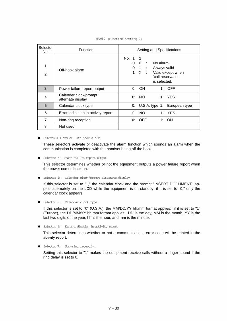
V – 30
WSW17 (Function setting 2)
FunctionSelector
No. Setting and Specifications
1
2Off-hook alarm
No. 1 20 0 : No alarm0 1 : Always valid1 X : Valid except when
‘call reservation’is selected.
Calender clock/promptalternate display 0: NO 1: YES4
8 Not used.
7 Non-ring reception 0: OFF 1: ON
6 Error indication in activity report 0: NO 1: YES
5 Calendar clock type 0: U.S.A. type 1: European type
3 Power failure report output 0: ON 1: OFF
Selectors 1 and 2: Off-hook alarm
These selectors activate or deactivate the alarm function which sounds an alarm when thecommunication is completed with the handset being off the hook.
Selector 3: Power failure report output
This selector determines whether or not the equipment outputs a power failure report whenthe power comes back on.
Selector 4: Calender clock/prompt alternate display
If this selector is set to "1," the calendar clock and the prompt "INSERT DOCUMENT" ap-pear alternately on the LCD while the equipment is on standby; if it is set to "0," only thecalendar clock appears.
Selector 5: Calendar clock type
If this selector is set to "0" (U.S.A.), the MM/DD/YY hh:mm format applies; if it is set to "1"(Europe), the DD/MM/YY hh:mm format applies: DD is the day, MM is the month, YY is thelast two digits of the year, hh is the hour, and mm is the minute.
Selector 6: Error indication in activity report
This selector determines whether or not a communications error code will be printed in theactivity report.
Selector 7: Non-ring reception
Setting this selector to "1" makes the equipment receive calls without a ringer sound if thering delay is set to 0.

V – 31
WSW18 (Function setting 3)
FunctionSelectorNo. Setting and Specifications
1 Not used.
No. 2 30 0 40 sec.0 1 0 sec. (No detection)1 0 5 sec.1 1 80 sec.
23
Detection enabled time for CNGand no tone
6 Registration of station ID 0: Permitted 1: Prohibited
No. 7 80 X : No monitoring1 0 : Up to phase B at the
calling station only1 1 : All transmission phases
both at the calling andcalled stations
7
8Tone sound monitoring
45
Not used.
Selectors 2 and 3: Detection enabled time for CNG and no tone
After the line is connected via the external telephone, the equipment can detect a CNG sig-nal or no tone for the time length specified by these selectors.
Selector 6: Registration of station ID
Setting this selector to "0" permits the registration of a station ID for Austrian and Czech ver-sions.
Selectors 7 and 8: Tone sound monitoring
These selectors set the monitoring specifications of the tone sound inputted from the line.

V – 32
WSW19 (Transmission speed setting)
FunctionSelectorNo.
No. 1 2 3No. 4 5 6
0 0 0 : 2,400 bps0 0 1 : 4,800 bps0 1 0 : 7,200 bps0 1 1 : 9,600 bps1 0 0 : 12,000 bps1 0 1 :1 1 0 : 14,400 bps1 1 1 :
Setting and Specifications
7
Last transmission speed choicefor fallback
First transmission speed choicefor fallback
8
Not used.
V.17 mode 0: Permitted 1: Prohibited
Selectors 1 through 6: First and last choices of transmission speed for fallback
These selectors are used to set the MODEM speed range. With the first transmission speedchoice specified by selectors 1 through 3, the equipment attempts to synchronize the datatransmission via the MODEM. If the synchronization fails, the equipment automatically stepsdown to the next lowest speed and attempts to synchronize the data transmission again.The equipment repeats this sequence while stepping down the transmission speed to thelast choice specified by selectors 4 through 6.
If the MODEM always falls back to a low transmission speed (e.g., 4,800 bps), set the firsttransmission speed choice to the lower one (e.g., modify it from 12,000 bps to 7,200 bps) inorder to deactivate the high-speed MODEM function and reduce the training time for shortertransmission time.
Generally, to save the transmission time, set the last transmission speed choice to a higherone.
1
|
3
4
|
6
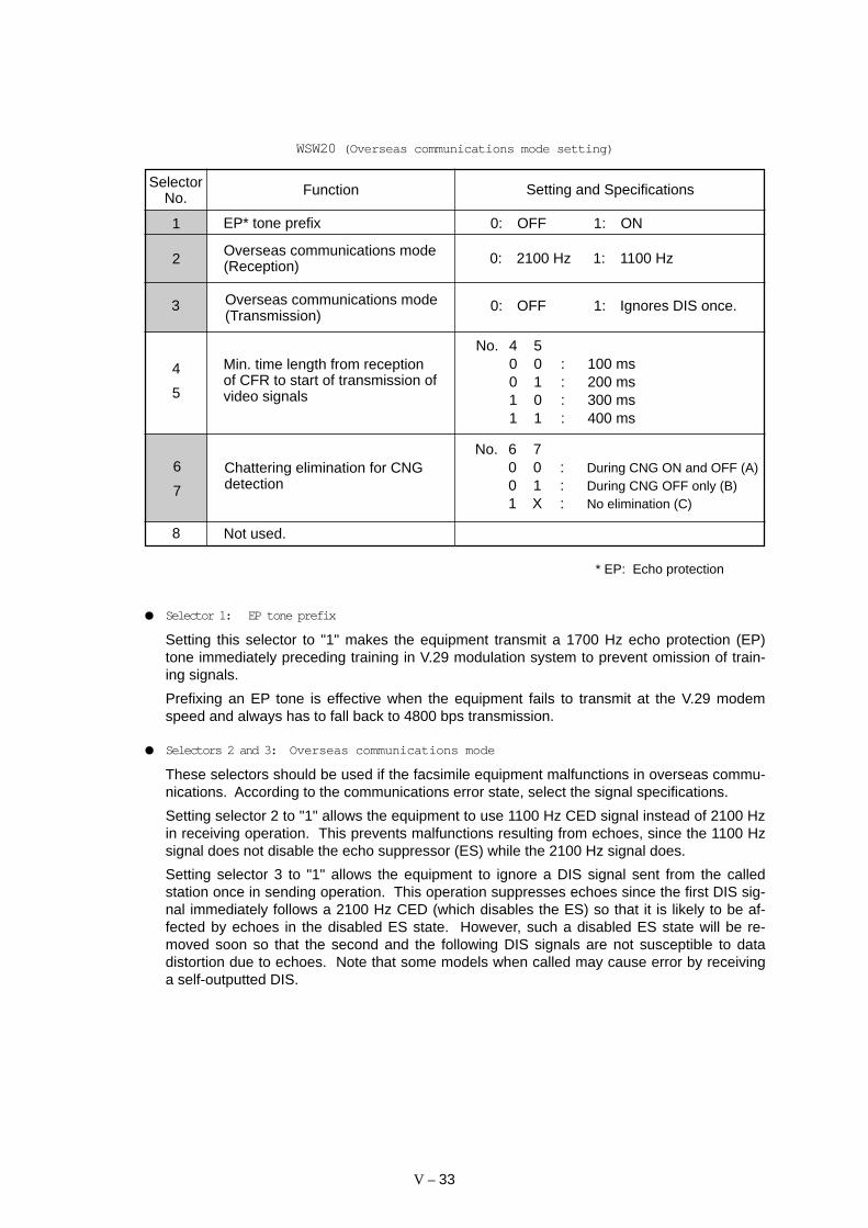
V – 33
WSW20 (Overseas communications mode setting)
FunctionSelectorNo.
Overseas communications mode(Transmission)
Setting and Specifications
1 EP* tone prefix 0: OFF 1: ON
2 0: 2100 Hz 1: 1100 HzOverseas communications mode(Reception)
3 0: OFF 1: Ignores DIS once.
No. 4 50 0 : 100 ms0 1 : 200 ms1 0 : 300 ms1 1 : 400 ms
4
5
Min. time length from receptionof CFR to start of transmission ofvideo signals
No. 6 70 0 : During CNG ON and OFF (A)0 1 : During CNG OFF only (B)1 X : No elimination (C)
6
7
Chattering elimination for CNGdetection
8 Not used.
* EP: Echo protection
Selector 1: EP tone prefix
Setting this selector to "1" makes the equipment transmit a 1700 Hz echo protection (EP)tone immediately preceding training in V.29 modulation system to prevent omission of train-ing signals.
Prefixing an EP tone is effective when the equipment fails to transmit at the V.29 modemspeed and always has to fall back to 4800 bps transmission.
Selectors 2 and 3: Overseas communications mode
These selectors should be used if the facsimile equipment malfunctions in overseas commu-nications. According to the communications error state, select the signal specifications.
Setting selector 2 to "1" allows the equipment to use 1100 Hz CED signal instead of 2100 Hzin receiving operation. This prevents malfunctions resulting from echoes, since the 1100 Hzsignal does not disable the echo suppressor (ES) while the 2100 Hz signal does.
Setting selector 3 to "1" allows the equipment to ignore a DIS signal sent from the calledstation once in sending operation. This operation suppresses echoes since the first DIS sig-nal immediately follows a 2100 Hz CED (which disables the ES) so that it is likely to be af-fected by echoes in the disabled ES state. However, such a disabled ES state will be re-moved soon so that the second and the following DIS signals are not susceptible to datadistortion due to echoes. Note that some models when called may cause error by receivinga self-outputted DIS.
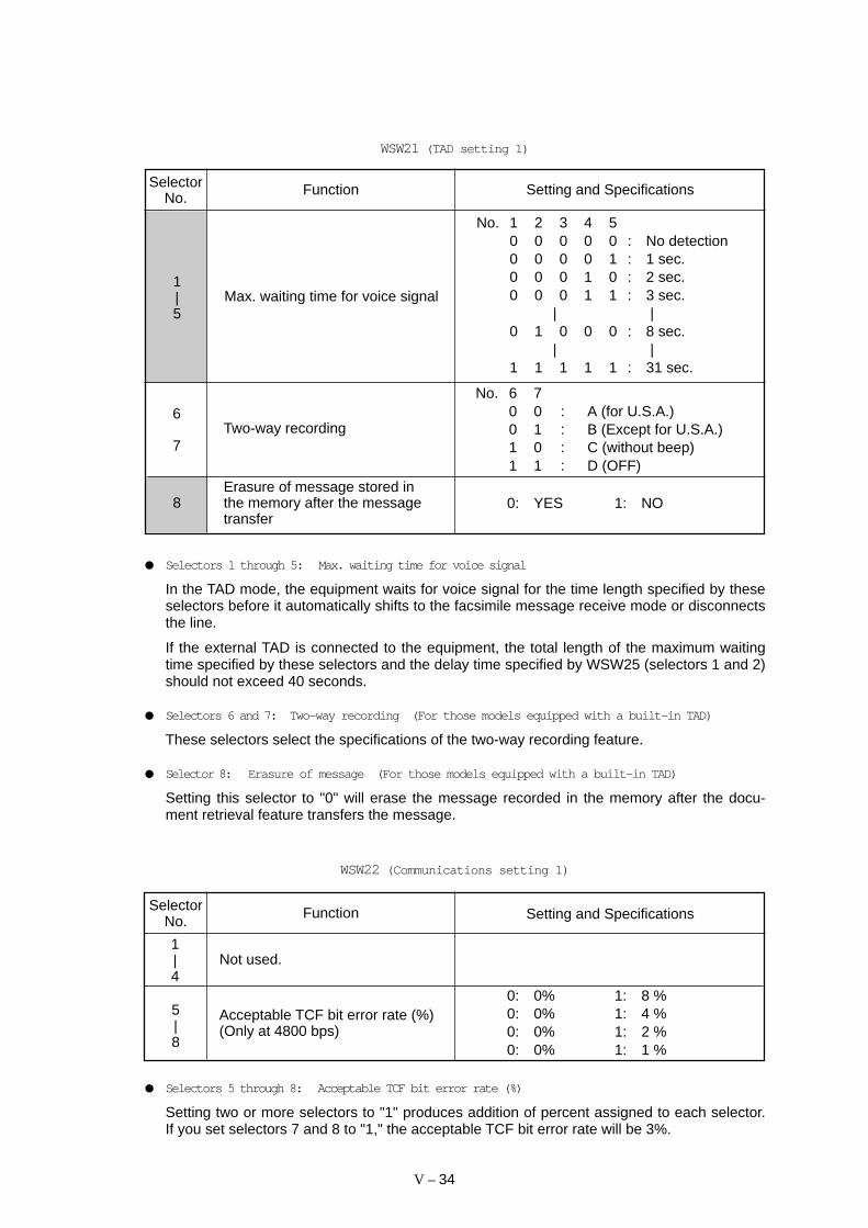
V – 34
WSW21 (TAD setting 1)
SelectorNo. Setting and SpecificationsFunction
No. 1 2 3 4 50 0 0 0 0 : No detection0 0 0 0 1 : 1 sec.0 0 0 1 0 : 2 sec.0 0 0 1 1 : 3 sec.
| |0 1 0 0 0 : 8 sec.
| |1 1 1 1 1 : 31 sec.
Max. waiting time for voice signal1|5
No. 6 70 0 : A (for U.S.A.)0 1 : B (Except for U.S.A.)1 0 : C (without beep)1 1 : D (OFF)
Two-way recording6
7
Erasure of message stored inthe memory after the messagetransfer
8 0: YES 1: NO
Selectors 1 through 5: Max. waiting time for voice signal
In the TAD mode, the equipment waits for voice signal for the time length specified by theseselectors before it automatically shifts to the facsimile message receive mode or disconnectsthe line.
If the external TAD is connected to the equipment, the total length of the maximum waitingtime specified by these selectors and the delay time specified by WSW25 (selectors 1 and 2)should not exceed 40 seconds.
Selectors 6 and 7: Two-way recording (For those models equipped with a built-in TAD)
These selectors select the specifications of the two-way recording feature.
Selector 8: Erasure of message (For those models equipped with a built-in TAD)
Setting this selector to "0" will erase the message recorded in the memory after the docu-ment retrieval feature transfers the message.
WSW22 (Communications setting 1)
FunctionSelectorNo. Setting and Specifications
1|4
Not used.
0: 0% 1: 8 %0: 0% 1: 4 %0: 0% 1: 2 %0: 0% 1: 1 %
5|8
Acceptable TCF bit error rate (%)(Only at 4800 bps)
Selectors 5 through 8: Acceptable TCF bit error rate (%)
Setting two or more selectors to "1" produces addition of percent assigned to each selector.If you set selectors 7 and 8 to "1," the acceptable TCF bit error rate will be 3%.

V – 35
WSW23 (Communications setting 2)
SelectorNo. Setting and Specifications
1Starting point of training check(TCF)
0: From the head of a series of zeros1: From any arbitrary point
No. 2 30 0 : 0%0 1 : 0.5%1 0 : 1%1 1 : 2%
Allowable training error rate2
3
Function
Decoding error rate for trans-mission of RTN
4
5
No. 4 50 0 : 16%0 1 : 14%1 0 : 10%1 1 : 8%
Selector 1: Starting point of training check (TCF)
At the training phase of the receiving operation, the called station detects for 1.0 second atraining check (TCF) command, a series of zeros which is sent from the calling station for 1.5seconds to verify training and give the first indication of the acceptability of the line.
This selector sets the starting point from which the called station should start counting thosezeros. If this selector is set to "0," the called station starts counting zeros 100 ms after thehead of a series of zeros is detected.
If it is set to "1," the called station starts counting zeros upon detection of 10-ms successivezeros 50 ms after the head of a series of zeros is detected. In this case, if the detection of10-ms successive zeros is too late, the data counting period will become less than 1.0 sec-ond, making the called station judge the line condition unacceptable.
Selectors 2 and 3: Allowable training error rate
The called station checks a series of zeros gathered in training (as described in Selector 1)according to the allowable training error rate set by these selectors. If the called stationjudges the line condition to be accepted, it responds with CFR; if not, it responds with FTT.
Selectors 4 and 5: Decoding error rate for transmission of RTN
The facsimile equipment checks the actual decoding errors and then transmits an RTN ac-cording to the decoding error rate (Number of lines containing an error per page ÷ Total num-ber of lines per page) set by these selectors.
Selector 6: Issue of RTN at the occurrence of a pagination error
If this selector is set to "0," the facsimile equipment transmits an RTN when a pagination er-ror occurs due to recording lag relative to receiving.
Limitation of attenuation level 0: YES 1: NO
0: YES 1: NO6Issue of RTN at the occurrenceof a pagination error
0: YES 1: NOResolution level for reception7
8
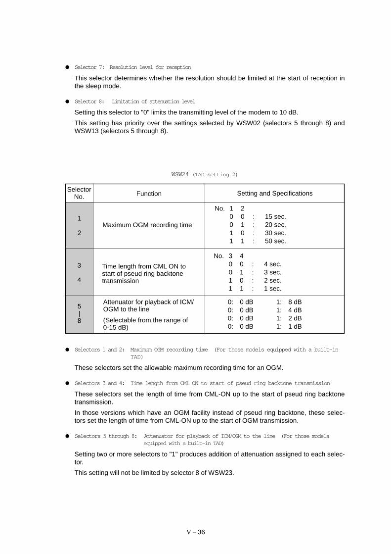
V – 36
Selector 7: Resolution level for reception
This selector determines whether the resolution should be limited at the start of reception inthe sleep mode.
Selector 8: Limitation of attenuation level
Setting this selector to "0" limits the transmitting level of the modem to 10 dB.
This setting has priority over the settings selected by WSW02 (selectors 5 through 8) andWSW13 (selectors 5 through 8).
FunctionSelector
No. Setting and Specifications
3
4
WSW24 (TAD setting 2)
1
2Maximum OGM recording time
No. 1 20 0 : 15 sec.0 1 : 20 sec.1 0 : 30 sec.1 1 : 50 sec.
Time length from CML ON tostart of pseud ring backtonetransmission
No. 3 40 0 : 4 sec.0 1 : 3 sec.1 0 : 2 sec.1 1 : 1 sec.
Attenuator for playback of ICM/OGM to the line
(Selectable from the range of0-15 dB)
5|8
0: 0 dB 1: 8 dB0: 0 dB 1: 4 dB0: 0 dB 1: 2 dB0: 0 dB 1: 1 dB
Selectors 1 and 2: Maximum OGM recording time (For those models equipped with a built-inTAD)
These selectors set the allowable maximum recording time for an OGM.
Selectors 3 and 4: Time length from CML ON to start of pseud ring backtone transmission
These selectors set the length of time from CML-ON up to the start of pseud ring backtonetransmission.
In those versions which have an OGM facility instead of pseud ring backtone, these selec-tors set the length of time from CML-ON up to the start of OGM transmission.
Selectors 5 through 8: Attenuator for playback of ICM/OGM to the line (For those modelsequipped with a built-in TAD)
Setting two or more selectors to "1" produces addition of attenuation assigned to each selec-tor.
This setting will not be limited by selector 8 of WSW23.

V – 37
SelectorNo. Setting and Specifications
WSW25 (TAD setting 3)
Function
1|4
Not used.
5|7
8 0: YES 1: NOAutomatic shift to facsimilemessage receive mode in ICMrecording mode
No. 5 6 70 0 0 : 2 sec.0 0 1 : 4 sec.0 1 0 : 6 sec.0 1 1 : 8 sec.1 0 0 : 10 sec.1 0 1 : 12 sec.1 1 0 : 14 sec.1 1 1 : 16 sec.
Pause between paging numberand PIN
Selectors 5 and 7: Pause between paging number and PIN (For those models equipped with abuilt-in TAD)
These selectors set the pause time between a telephone number being paged and PIN (pri-vate identification number) for the paging feature.
Selector 8: Automatic shift to facsimile message receive mode in ICM recording mode (Forthose models equipped with a built-in TAD)
If this selector is set to "0", the equipment automatically shifts to the facsimile message re-ceive mode after recording an ICM. If it is set to "1", the equipment automatically discon-nects the line after the waiting time has passed.
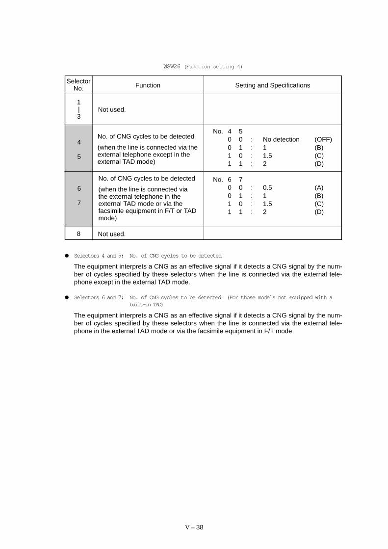
V – 38
SelectorNo.
4
5
6
7
WSW26 (Function setting 4)
Function Setting and Specifications
No. 4 50 0 : No detection (OFF)0 1 : 1 (B)1 0 : 1.5 (C)1 1 : 2 (D)
No. 6 70 0 : 0.5 (A)0 1 : 1 (B)1 0 : 1.5 (C)1 1 : 2 (D)
No. of CNG cycles to be detected
(when the line is connected via theexternal telephone except in theexternal TAD mode)
No. of CNG cycles to be detected
(when the line is connected viathe external telephone in theexternal TAD mode or via thefacsimile equipment in F/T or TADmode)
1|3
Not used.
8 Not used.
Selectors 4 and 5: No. of CNG cycles to be detected
The equipment interprets a CNG as an effective signal if it detects a CNG signal by the num-ber of cycles specified by these selectors when the line is connected via the external tele-phone except in the external TAD mode.
Selectors 6 and 7: No. of CNG cycles to be detected (For those models not equipped with abuilt-in TAD)
The equipment interprets a CNG as an effective signal if it detects a CNG signal by the num-ber of cycles specified by these selectors when the line is connected via the external tele-phone in the external TAD mode or via the facsimile equipment in F/T mode.
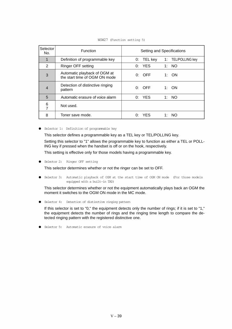
V – 39
FunctionSelectorNo. Setting and Specifications
WSW27 (Function setting 5)
Detection of distinctive ringingpattern
1
2 Ringer OFF setting 0: YES 1: NO
Automatic playback of OGM atthe start time of OGM ON mode3 0: OFF 1: ON
5 Automatic erasure of voice alarm 0: YES 1: NO
4 0: OFF 1: ON
Not used.67
8 0: YES 1: NOToner save mode.
Selector 1: Definition of programmable key
This selector defines a programmable key as a TEL key or TEL/POLLING key.
Setting this selector to "1" allows the programmable key to function as either a TEL or POLL-ING key if pressed when the handset is off or on the hook, respectively.
This setting is effective only for those models having a programmable key.
Selector 2: Ringer OFF setting
This selector determines whether or not the ringer can be set to OFF.
Selector 3: Automatic playback of OGM at the start time of OGM ON mode (For those modelsequipped with a built-in TAD)
This selector determines whether or not the equipment automatically plays back an OGM themoment it switches to the OGM ON mode in the MC mode.
Selector 4: Detection of distinctive ringing pattern
If this selector is set to "0," the equipment detects only the number of rings; if it is set to "1,"the equipment detects the number of rings and the ringing time length to compare the de-tected ringing pattern with the registered distinctive one.
Selector 5: Automatic erasure of voice alarm
Definition of programmable key 0: TEL key 1: TEL/POLLING key

V – 40
FunctionSelectorNo. Setting and Specifications
1
2
3
Transmission level of DTMFhigh-band frequency signal
No. 1 2 30 0 0 : 0 dB0 0 1 : +1 dB0 1 0 : +2 dB0 1 1 : +3 dB1 0 0 : 0 dB1 0 1 : –1 dB1 1 0 : –2 dB1 1 1 : –3 dB
4
5
6
Transmission level of DTMFlow-band frequency signal
No. 4 5 60 0 0 : 0 dB0 0 1 : +1 dB0 1 0 : +2 dB0 1 1 : +3 dB1 0 0 : 0 dB1 0 1 : –1 dB1 1 0 : –2 dB1 1 1 : –3 dB
This selector determines whether or not the voice alarm should be erased from the memory
0: Standard resolution statement1: Non-standard resolution statement
7 Resolution definition
Not used.8
after it is issued.
WSW28 (Function setting 6)
Selectors 1 through 6: Transmission level of DTMF high-/low-band frequency signal
These selectors are intended for the manufacturer who tests the equipment for the Standard.Never access them.
Selector 7: Resolution definition
This selector determines whether the equipment issues a standard or non-standard (fine/su-perfine) resolution statement when the empty space of the memory shared by the receivebuffer and recording buffer becomes insufficient to receive data at high resolution.
If this selector is set to "0," the equipment issues a standard resolution statement which in-forms the calling station that the station called can receive data only at the standard resolu-tion.
If it is set to "1," the FAX3550/8000P/MFC4550/6550MC issues a fine resolution statementand the MFC7550MC/9000/9500 issues a superfine resolution statement. (NOTE: TheFAX3550/8000P/MFC4550/6550MC having an optional memory issues a superfine resolu-tion statement.)
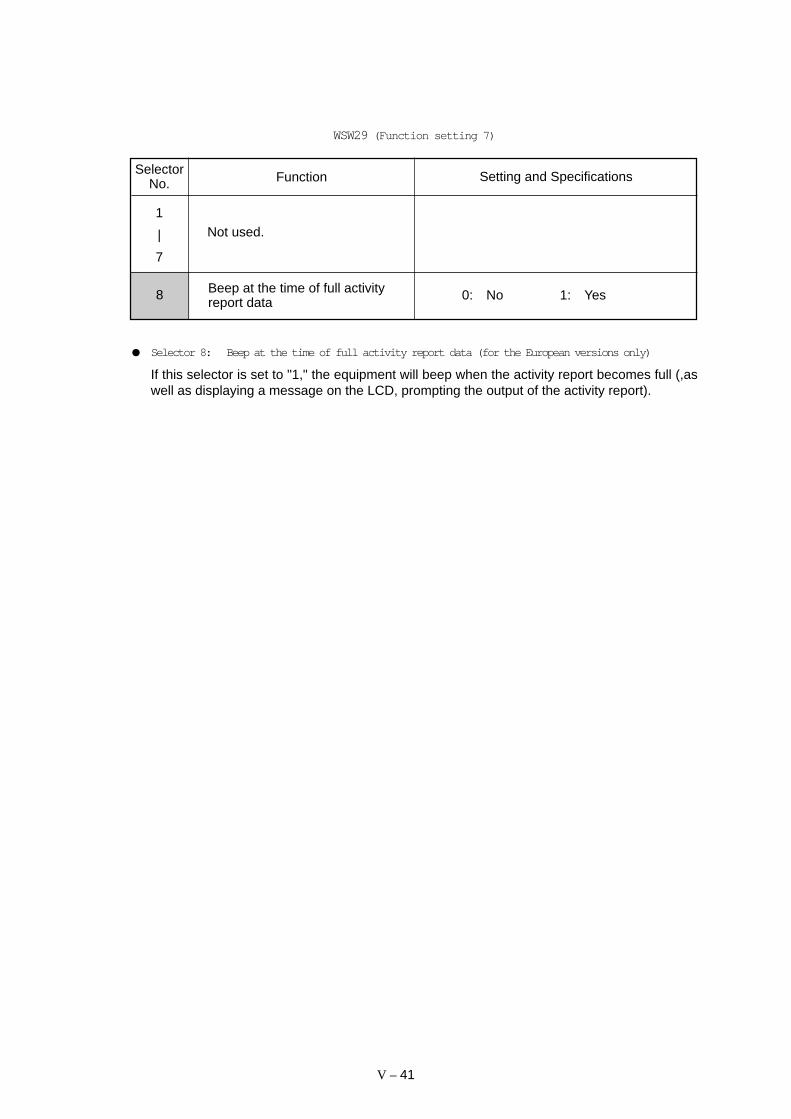
V – 41
Setting and Specifications
WSW29 (Function setting 7)
SelectorNo. Function
Not used.1
|
7
0: No 1: Yes8 Beep at the time of full activityreport data
Selector 8: Beep at the time of full activity report data (for the European versions only)
If this selector is set to "1," the equipment will beep when the activity report becomes full (,aswell as displaying a message on the LCD, prompting the output of the activity report).

V – 42
FunctionSelectorNo. Setting and Specifications
No. 1 2 30 0 0 : -38.0 dBm (A)0 0 1 : -39.5 dBm (B)0 1 0 : -41.0 dBm (C)0 1 1 : -42.5 dBm (D)1 0 0 : -44.0 dBm (E)1 0 1 : -45.5 dBm (F)1 1 0 : -47.0 dBm (G)1 1 1 : -48.5 dBm (H)
Detection level of dial tone orbusy tone for the built-in TADoperation
WSW30 (Function setting 8)
1
2
3
5 Speaker output level 0: Higher 1: Lower
4 Not used.
No. 6 70 0 : A0 1 : B1 x : C
Cooling fan control mode6
7
Not used.8
0(Higher)
1(Lower)
Speaker Volume Switch Position
Selector 5 of WSW30
HIGH Medium-HighHigh
LOW Medium-Low Low
Selectors 1 through 3: Detection level of dial tone or busy tone for built-in TAD operation (Forthose models equipped with a built-in TAD)
If dial tone or busy tone inputted during ICM recording is below the level specified by theseselectors, the TAD stops recording and disconnects the line.
Selector 5: Speaker output level (For those models equipped with a built-in TAD)
This selector determines the speaker output level when the speaker volume switch is set toHIGH or LOW, as listed below.
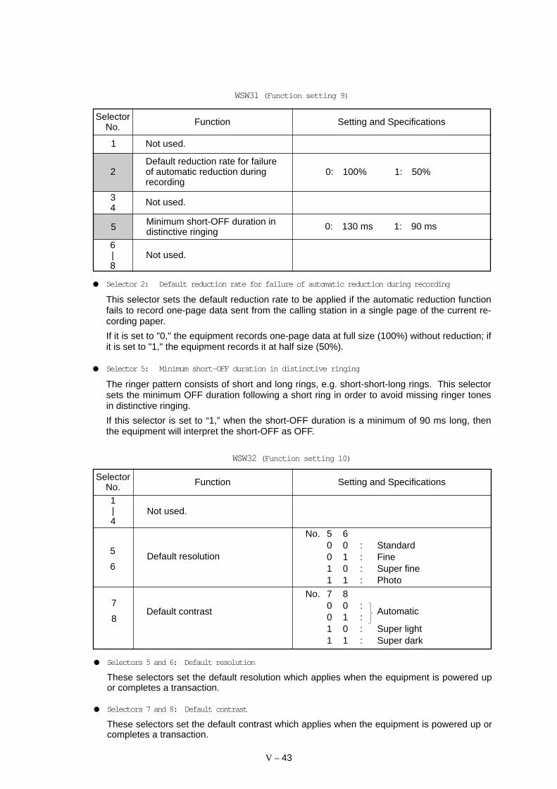
V – 43
WSW31 (Function setting 9)
FunctionSelectorNo. Setting and Specifications
1 Not used.
Default reduction rate for failureof automatic reduction duringrecording
0: 100% 1: 50%2
6|8
Not used.
0: 130 ms 1: 90 ms5 Minimum short-OFF duration indistinctive ringing
34
Not used.
Selector 2: Default reduction rate for failure of automatic reduction during recording
This selector sets the default reduction rate to be applied if the automatic reduction functionfails to record one-page data sent from the calling station in a single page of the current re-cording paper.
If it is set to "0," the equipment records one-page data at full size (100%) without reduction; ifit is set to "1," the equipment records it at half size (50%).
Selector 5: Minimum short-OFF duration in distinctive ringing
The ringer pattern consists of short and long rings, e.g. short-short-long rings. This selectorsets the minimum OFF duration following a short ring in order to avoid missing ringer tonesin distinctive ringing.
If this selector is set to “1,” when the short-OFF duration is a minimum of 90 ms long, thenthe equipment will interpret the short-OFF as OFF.
WSW32 (Function setting 10)
FunctionSelectorNo. Setting and Specifications
1|4
Not used.
No. 5 60 0 : Standard0 1 : Fine1 0 : Super fine1 1 : Photo
Default resolution5
6
No. 7 80 0 :
Automatic0 1 :1 0 : Super light1 1 : Super dark
Default contrast7
8
Selectors 5 and 6: Default resolution
These selectors set the default resolution which applies when the equipment is powered upor completes a transaction.
Selectors 7 and 8: Default contrast
These selectors set the default contrast which applies when the equipment is powered up orcompletes a transaction.
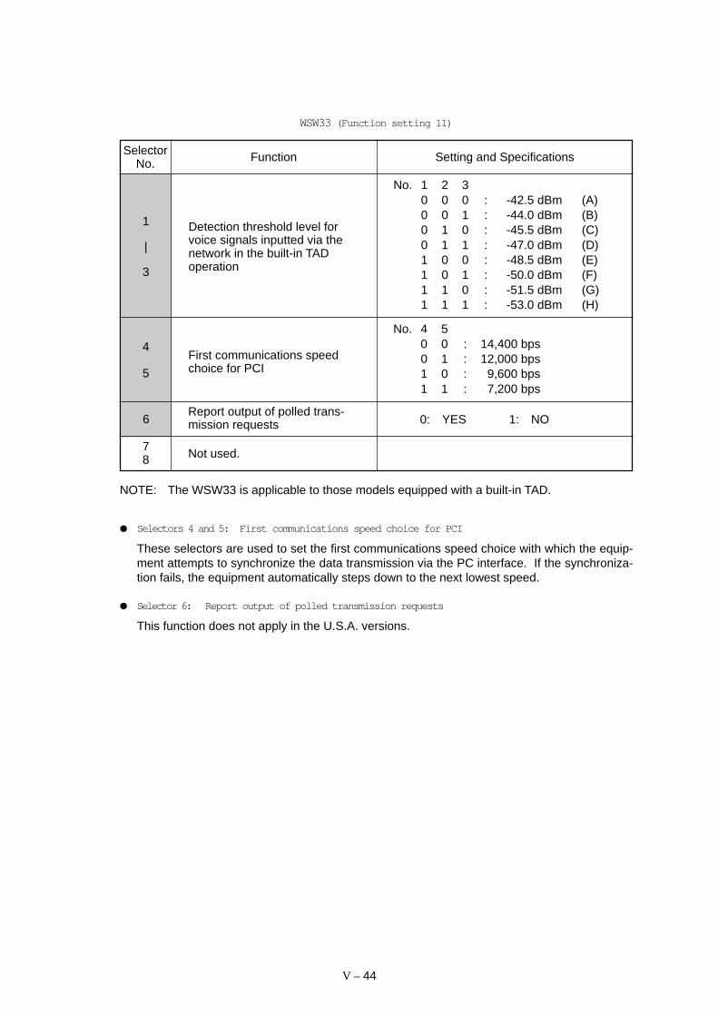
V – 44
1
|
3
No. 1 2 30 0 0 : -42.5 dBm (A)0 0 1 : -44.0 dBm (B)0 1 0 : -45.5 dBm (C)0 1 1 : -47.0 dBm (D)1 0 0 : -48.5 dBm (E)1 0 1 : -50.0 dBm (F)1 1 0 : -51.5 dBm (G)1 1 1 : -53.0 dBm (H)
Detection threshold level forvoice signals inputted via thenetwork in the built-in TADoperation
WSW33 (Function setting 11)
4
5
No. 4 50 0 : 14,400 bps0 1 : 12,000 bps1 0 : 9,600 bps1 1 : 7,200 bps
Report output of polled trans-mission requests6 0: YES 1: NO
First communications speedchoice for PCI
FunctionSelectorNo. Setting and Specifications
78 Not used.
NOTE: The WSW33 is applicable to those models equipped with a built-in TAD.
Selectors 4 and 5: First communications speed choice for PCI
These selectors are used to set the first communications speed choice with which the equip-ment attempts to synchronize the data transmission via the PC interface. If the synchroniza-tion fails, the equipment automatically steps down to the next lowest speed.
Selector 6: Report output of polled transmission requests
This function does not apply in the U.S.A. versions.

V – 45
WSW34 (Function setting 12)
FunctionSelectorNo. Setting and Specifications
No. 1 2 30 0 0 : 0 second0 0 1 : 1 second0 1 0 : 2 seconds0 1 1 : 3 seconds1 0 0 : 4 seconds1 0 1 : 5 seconds1 1 0 : 6 seconds1 1 1 : 7 seconds
1
|
3
ICM recording time to be erasedpreceding the tone detectionwhen the equipment automaticallydisconnects the line because novoice signal has been received
45 Not used.
Not used.8
6
7
No. 6 70 0 : 30 1 : 21 0 : 11 1 : OFF
Number of DTMF tone signals forinhibiting the detection of CNGduring external TAD operation
Selectors 6 and 7: Number of DTMF tone signals for inhibiting the detection of CNG duringexternal TAD operation
If the equipment receives this specified number of DTMF tone signals during external TADoperation, it will not detect CNG afterwards.
If these selectors are set to "1, 1," the CNG detection will not be inhibited.
V – 46
[ B ] Printout of firmware switch data
Function
The equipment prints out the setting items and contents specified by the firmware switches.
Operating Procedure
(1) Press the 1 key twice in the initial maintenance mode.
The "PRINTING" will appear on the LCD.
(2) The equipment prints out the configuration list as shown in the figure below.
(3) Upon completion of printing, the equipment returns to the initial maintenance mode.
Configuration List

V – 47
3.7 Operational Check of Control Panel PCB
Function
This function checks the control panel PCB for normal operation.
Operating Procedure
(1) Press the 1 and 3 keys in this order in the initial maintenance mode.
The "00 " will appear on the LCD.
(2) Press the keys and buttons in the order designated in the illustration shown below.
The LCD shows the corresponding number in decimal notation each time a key or but-ton is pressed. Check that the displayed number is correct by referring to the illustra-tion below.
If a key or button is pressed out of order, the equipment beeps and displays the "IN-VALID OPERATE" on the LCD. To return to the status ready to accept key & buttonentry for operational check, press the Stop key.
(3) After the last number key or button is pressed, the equipment beeps for 1 second.
(4) To terminate this operation, press the Stop key. The equipment returns to the initialmaintenance mode.
Key & Button Entry Order (1)
LineOn/Off
FF/Cont
PrintPriority
Test/
Copy
Photo
Reset
01 02 03
13 14 15
07 08 09
19 20 21
10 11 12
22 23 24
04 05 06
16 17 18
Reduce
Enlarge
Function Clear Tel-indexSet HelpSuperQ.ScanResolution Mode Coverpage
Stop
Start
Shift
Hook
Hold
Speed Dial
1
4
7
5 6
2 3
8 9
0
A BC DE F
GH I JKL MNO
PQRS TUV WXYZ
MFC 4550FinePhotoS.Fine FAX PRINTER COPIER SCANNER PC FAX
Redial / Pause
FaxTADF/ T
status
status
FAX3550/8000P
01 02 03
21 22 23
11 12 13
31 32 33
16 17 18
36 37 38
06 07 08
26 27 28 Stop
Start
Shift
Hook
Hold
Speed Dial
1
4
7
5 6
2 3
8 9
0
A BC DE F
GH I JKL MNO
PQRS TUV WXYZ
04 05
24 25
14 15
34 35
19 20
39 40
09 10
29 30
Redial / Pause
Function Clear Tel-indexSet Enlarge /ReduceHelpSuper Q.ScanResolution Mode
3550FinePhotoS.Fine
FaxTADF/ T
Copy
MFC4550/9000

V – 48
MFC6550MC/7550MC/9500
Key & Button Entry Order (2)
LineOn/Off
FF/Cont
PrintPriority
Test/
Copy
Photo
Reset
01 02 03
13 14 15
07 08 09
19 20 21
10 11 12
22 23 24
04 05 06
16 17 18
ReduceEnlarge/
Sort
Function Clear Tel-indexSet HelpSuperQ.ScanResolution Mode Coverpage
Stop
Start
Shift
Hook
Hold
Speed Dial
1
4
7
5 6
2 3
8 9
0
A BC DE F
GH I JKL MNO
PQRS TUV WXYZ
status
status
Redial / Pause
Record Erase
Speaker HL
Play
MFC 7550MC
FAX PRINTER COPIER SCANNER PC FAX MESSAGE CENTERSIX IN ONE
FinePhotoS.Fine
Fax
F/ T
Voice Fax
status
3.8 Sensor Operational Check
Function
This function allows you to check whether the eight sensors (document front sensor, docu-ment rear sensor, sheet feeder cover sensor, cover sensor, registration sensor, paper ejec-tion sensor, toner sensor, and hook switch sensor) operate normally.
The LED shows the “FRRETCCVRGHATNHK” when
- the document front sensor detects no paper (FR),
- the document rear sensor detects no paper (RE),
- the sheet feeder cover is closed (TC),
- the top cover is closed (CV),
- the registration sensor detects no paper (RG),
- the paper ejection sensor detects no paper (HA),
- the toner sensor detects toner (TN), and
- the hook switch sensor detects the on-hook state (HK).
Operating Procedure
(1) Press the 3 and 2 keys in this order in the initial maintenance mode.
The LCD should show "FRRETCCVRGHATNHK" if the detecting conditions of the ninesensors are as defined above.
(2) Change the detecting conditions (e.g., insert paper through the document sensors orthe registration sensor, open the sheet feeder cover or the top cover, jam paper at thepaper outlet, remove the toner cartridge, and lift up the handset), and then check thatthe indication on the LCD changes according to the sensor states.
(3) To stop this operation and return the equipment to the initial maintenance mode, pressthe Stop key.
V – 49
3.9 CCD Scanner Area Setting
Function
The equipment sets the CCD scanner area and stores it into the E2PROM.
Operating Procedure
(1) Press the 5 key twice in the initial maintenance mode.
The "SCANNER AREA SET" will appear on the LCD.
The equipment checks and sets the area to be scanned.
If no error is noted, the equipment returns to the initial maintenance mode.
If any error is noted, the "SCANNER ERROR" will appear on the LCD. To return theequipment to the initial maintenance mode, press the Stop key.
3.10 Equipment Error Code Indication
Function
This function displays the error code for the last error on the LCD.
Operating Procedure
(1) Press the 8 and 2 keys in this order in the initial maintenance mode.
The LCD shows "MACHINE ERROR XX."
(2) To stop this operation and return the equipment to the initial maintenance mode,press the Stop key.
V – 50
3.11 Output of Transmission Log to the Line
Function
This function outputs the transmission log (that the equipment has stored about the latesttransmission) to the line. It allows the service personnel to receive the transmission log ofthe user’s equipment at a remote location and use it for analyzing problems arising in theuser’s equipment.
Operating Procedure
(1) If the user’s equipment has a transmission-related problem, call the user’s equipment ata remote location from your equipment.
(2) If the line is connected, have the user perform the following:
1) Press the Function key and the Mode key in this order.
2) Press the 0 , 8 , and 7 keys.
The above operation makes the user’s equipment send CNG to your equipment forsending the transmission log.
(3) If you hear the CNG sent from the user’s equipment, press the Start key of yourequipment.
Your equipment will start to receive the transmission log from the user’s equipment.

CHAPTER VI .
ERROR INDICATION ANDTROUBLESHOOTING
CONTENTS
1. ERROR INDICATION ..................................................................................... VI -1
1.1 Equipment Errors .................................................................................... VI -1
[ 1 ] Error messages on the LCD ........................................................ VI -1
[ 2 ] Error codes shown in the “MACHINE ERROR xx” message ...... VI -3
1.2 Communications Errors .......................................................................... VI -5
2. TROUBLESHOOTING ................................................................................... VI -12
2.1 Introduction ............................................................................................. VI -12
2.2 Precautions ............................................................................................. VI -12
2.3 Checking prior to Troubleshooting .......................................................... VI -12
2.4 Troubleshooting Procedures................................................................... VI -13
[ 1 ] Control panel related ................................................................... VI -13
[ 2 ] Telephone related ........................................................................ VI -13
[ 3 ] Communications related .............................................................. VI -14
[ 4 ] Paper/document feeding related ................................................. VI -14
[ 5 ] Print-image related ...................................................................... VI -15

VI – 1
1. ERROR INDICATION
To help the user or the service personnel promptly locate the cause of a problem (if any), thefacsimile equipment incorporates the self-diagnostic functions which display error messagesfor equipment errors and communications errors.
For the communications errors, the equipment also prints out the transmission verification re-port and the communications list.
1.1 Equipment Errors
If an equipment error occurs, the facsimile equipment emits an audible alarm (continuous beep-ing) for approximately 4 seconds and shows the error message on the LCD. For the errormessages, see [ 1 ] below. As one of the error messages, “MACHINE ERROR xx” includes anerror code which indicates the detailed error causes listed in [ 2 ]. To display an error code forthe other latest error message, make the equipment enter the maintenance mode and press8 and 2 keys (for details, refer to Chapter V, Section 3.11).
[ 1 ] Error messages on the LCD
Messages on the LCD Probable Cause
CHECK PAPER Even after paper pulling-in operation, the registration sensordoes not detect paper.
COVER OPEN The cover sensor detects that the top cover is not closed or thesheet feeder cover sensor detects that the sheet feeder coveris not closed.
PRINTER JAM (1) The paper ejection sensor stays OFF even after theregistration sensor has gone OFF and the paper has beenfed by the specified amount.
(2) The paper ejection sensor stays ON even after it has cameON and the paper has been fed by the specified amount.
DOCUMENT JAM Document jam
(1) The document length exceeds the limitation (400 or 90 cm)registered by firmware switch WSW16. (Refer to ChapterV, Section 3.6.)(Both the document front and rear sensors stay ON afterthe document has been fed by the registered length.)
(2) The document rear sensor detects no trailing edge of adocument after the document has been fed by 400 cm.(The document rear sensor stays ON even after thedocument has been fed when the document front and rearsensors were OFF and ON, respectively.)
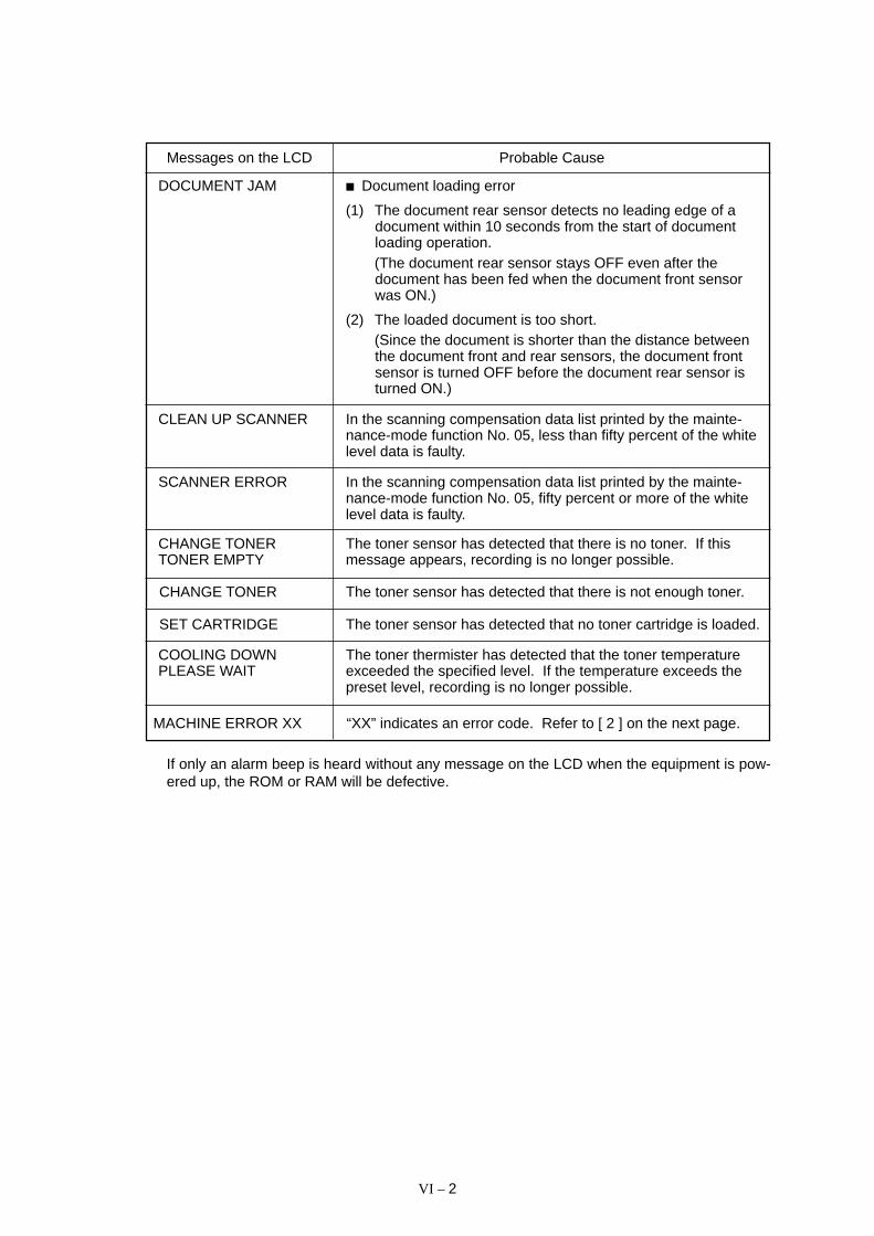
VI – 2
Messages on the LCD Probable Cause
DOCUMENT JAM Document loading error
(1) The document rear sensor detects no leading edge of adocument within 10 seconds from the start of documentloading operation.(The document rear sensor stays OFF even after thedocument has been fed when the document front sensorwas ON.)
(2) The loaded document is too short.(Since the document is shorter than the distance betweenthe document front and rear sensors, the document frontsensor is turned OFF before the document rear sensor isturned ON.)
CLEAN UP SCANNER In the scanning compensation data list printed by the mainte-nance-mode function No. 05, less than fifty percent of the whitelevel data is faulty.
SCANNER ERROR In the scanning compensation data list printed by the mainte-nance-mode function No. 05, fifty percent or more of the whitelevel data is faulty.
CHANGE TONERTONER EMPTY
The toner sensor has detected that there is no toner. If thismessage appears, recording is no longer possible.
CHANGE TONER The toner sensor has detected that there is not enough toner.
SET CARTRIDGE The toner sensor has detected that no toner cartridge is loaded.
COOLING DOWNPLEASE WAIT
The toner thermister has detected that the toner temperatureexceeded the specified level. If the temperature exceeds thepreset level, recording is no longer possible.
MACHINE ERROR XX “XX” indicates an error code. Refer to [ 2 ] on the next page.
If only an alarm beep is heard without any message on the LCD when the equipment is pow-ered up, the ROM or RAM will be defective.

VI – 3
82 Paper feeding error.
( 83 Paper jam. The registration sensor remains ON.)
( 84 Paper jam. The paper ejection sensor remains ON. )
87 Fails to complete the recording operation sequence.
( 88 Paper jam. Even after the registration sensor has gone OFF, the paperejection sensor still stays OFF.)
8B Overheating error.
( A1 Top cover opened. )
( A2 Document too long to scan. )
( A3 Document not detected by the document rear sensor. )
( A4 50% or more faulty of white level data. )
[ 2 ] Error codes shown in the “MACHINE ERROR xx” message
Error factorError Code
xx(Hex.)
71 Laser scanner motor does not lock.
72 Cannot detect Beam Detect signal.
73 No toner cartridge loaded.
74 Toner empty.
75 In-house temperature error.
76 Fixing heater harness disconnected or broken.
77 Heater thermister shortcircuit.
78 Heater thermister harness disconnected or broken.
79 Toner thermister disconnected or broken.
80 Paper size setting error.
A5 Faulty operation of DMA0 during scanning.
A6 Faulty operation of DMA1 during scanning.
A7 One-line feeding time-out error.
A8 One-line scanning time-out error.
A9 Abnormal scanning reference voltage.
AB Document feed-in amount measuring error.
AC Less than 50% faulty of white level data.
B1 CODEC LSI error.
( B8 Amplifier gain error. )
( B9 Light emission intensity error of the LED array. )
( BA Scanning error: The left-hand black reference line which is marked onthe document pressure bar for scanning width setting is not detected.)
Error codes in parentheses do not appear in the “MACHINE ERROR xx”, since those errors are displayed asmessages described in "[ 1 ] Error messages on the LCD." Those error codes appear in the communicationserror list if an equipment error occurs during communications. Refer to Section 1.2, (13).
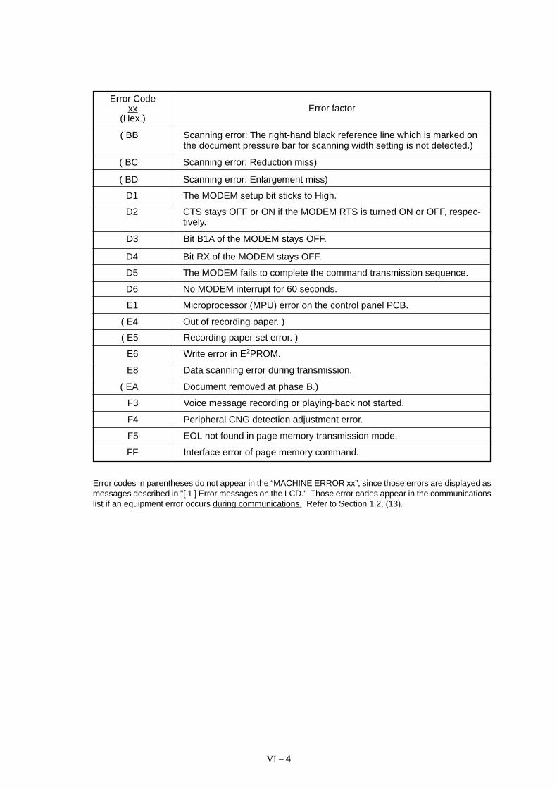
VI – 4
Error factorError Code
xx(Hex.)
( BB Scanning error: The right-hand black reference line which is marked onthe document pressure bar for scanning width setting is not detected.)
( BC Scanning error: Reduction miss)
( BD Scanning error: Enlargement miss)
D1 The MODEM setup bit sticks to High.
D2 CTS stays OFF or ON if the MODEM RTS is turned ON or OFF, respec-tively.
D3 Bit B1A of the MODEM stays OFF.
D4 Bit RX of the MODEM stays OFF.
D5 The MODEM fails to complete the command transmission sequence.
D6 No MODEM interrupt for 60 seconds.
E1 Microprocessor (MPU) error on the control panel PCB.
( E4 Out of recording paper. )
( E5 Recording paper set error. )
E6 Write error in E2PROM.
E8 Data scanning error during transmission.
( EA Document removed at phase B.)
F3 Voice message recording or playing-back not started.
F4 Peripheral CNG detection adjustment error.
F5 EOL not found in page memory transmission mode.
FF Interface error of page memory command.
Error codes in parentheses do not appear in the “MACHINE ERROR xx”, since those errors are displayed asmessages described in "[ 1 ] Error messages on the LCD." Those error codes appear in the communicationslist if an equipment error occurs during communications. Refer to Section 1.2, (13).

VI – 5
1.2 Communications Errors
If a communications error occurs, the facsimile equipment
(1) emits an audible alarm (intermittent beeping) for approximately 4 seconds,
(2) displays the corresponding error message, and
(3) prints out the transmission verification report if the equipment is in sending operation.

VI – 6
Definition of Error Codes on the Communications List
(1) Calling
10 08 Wrong number called.
11 01 No dial tone detected.
11 02 Busy tone detected before dialing.
11 03 2nd dial tone not detected.
11 05 No loop current detected. *
11 06 Busy tone detected after dialing or called.
11 07 No response from the remote station in sending.
11 10 No tone detected after dialing.
17 07 No response from the calling station in receiving.
* Available in Germany and Austria only.
Code 1 Code 2 Causes
(2) Command reception
Code 1 Code 2 Causes
20 01 Unable to detect a flag field.
20 02 Carrier was OFF for 200 ms or longer.
20 03 Abort detected (“1” in succession for 7 bits or more).
20 04 Overrun detected.
20 05 A frame for 3 seconds or more received.
20 06 CRC error in answer back.
20 07 Undefined command received.
20 08 Invalid command received.
20 09 Command ignored once for document setting or for dump-ing-out at turn-around transmission.
20 0A T5 time-out error
20 0B CRP received.
20 0C EOR and NULL received.
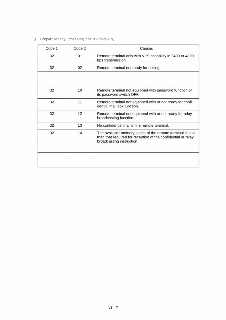
VI – 7
(3) Compatibility [checking the NSF and DIS]
Code 1 Code 2 Causes
32 01 Remote terminal only with V.29 capability in 2400 or 4800bps transmission.
32 02 Remote terminal not ready for polling.
32 10 Remote terminal not equipped with password function orits password switch OFF.
32 11 Remote terminal not equipped with or not ready for confi-dential mail box function.
32 12 Remote terminal not equipped with or not ready for relaybroadcasting function.
32 13 No confidential mail in the remote terminal.
32 14 The available memory space of the remote terminal is lessthan that required for reception of the confidential or relaybroadcasting instruction.

VI – 8
50 01 Vertical resolution capability changed after compensationof background color.
40 02 Illegal coding system requested.
40 03 Illegal recording width requested.
40 05 ECM requested although not allowed.
40 06 Polled while not ready.
40 07 No document to send when polled.
40 10 Nation code or manufacturer code not coincident.
40 11 Unregistered group code entered for relay broadcastingfunction, or the specified number of broadcasting subscrib-ers exceeding the limit.
40 12 Retrieval attempted when not ready for retrieval.
40 13 Polled by any other manufacturers’ terminal while waitingfor secure polling.
40 17 Invalid resolution selected.
(4) Instructions received from the remote terminal [checking the NSC, DTC, NSS, and DCS]
Code 1 Code 2 Causes
(5) Command reception [checking the NSF and DIS after transmission of NSS and DCS]
Code 1 Code 2 Causes

VI – 9
63 01 Password plus "lower 4 digits of telephone number" notcoincident.
63 02 Password not coincident.
63 03 Polling ID not coincident.
63 04 Entered confidential mail box ID uncoincident with the mailbox ID.
63 05 Relay broadcasting ID not coincident.
63 06 Entered retrieval ID uncoincident with that of the mail boxID.
Code 1 Code 2 Causes
(6) ID checking
(7) DCN reception
Code 1 Code 2 Causes
74 DCN received.
(8) TCF transmission/reception
Code 1 Code 2 Causes
80 01 Fallback impossible.

VI – 10
A0 03 Error correction sequence not terminated even at the finaltransmission speed for fallback.
A0 11 Receive buffer empty. (5-second time-out)
A0 12 Receive buffer full during operation except receiving intomemory.
A0 13 Decoding error continued on 500 lines.
A0 14 Decoding error continued for 10 seconds.
A0 15 Time-out: Five seconds or more for one-line transmission.
A0 16 RTC not found and carrier OFF signal detected for 6seconds.
A0 17 RTC found and command detected for 60 seconds.
A0 18 Receive buffer full on memory reception.
A8 01 RTN, PIN, or ERR received at the calling terminal. *
A9 01 RTN, PIN, or ERR received at the called terminal. *
* Available in Germany and Austria only.
Code 1 Code 2 Causes
(9) Signal isolation
90 01 Unable to detect video signals and commands within 6seconds after CFR is transmitted.
90 02 Received PPS containing invalid page count or blockcount.
Code 1 Code 2 Causes
(10) Video signal reception
(11) General communications-related
Code 1 Code 2 Causes
B0 01 Polarity inversion detected.
B0 02 Unable to receive the next-page data.
B0 03 Unable to receive polling even during turn-around trans-mission due to call reservation.
B0 04 PC interface error.
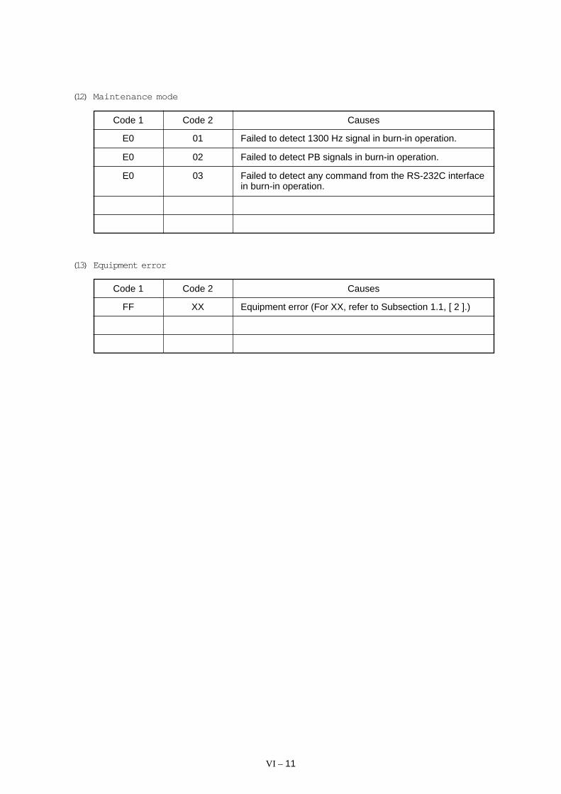
VI – 11
(12) Maintenance mode
Code 1 Code 2 Causes
E0 01 Failed to detect 1300 Hz signal in burn-in operation.
E0 02 Failed to detect PB signals in burn-in operation.
E0 03 Failed to detect any command from the RS-232C interfacein burn-in operation.
Code 1 Code 2 Causes
(13) Equipment error
FF XX Equipment error (For XX, refer to Subsection 1.1, [ 2 ].)
VI – 12
2. TROUBLESHOOTING
2.1 Introduction
This section gives the service personnel some of the troubleshooting procedures to be fol-lowed if an error or malfunction occurs with the facsimile equipment. It is impossible to an-ticipate all of the possible problems which may occur in future and determine the trouble-shooting procedures, so this section covers some sample problems. However, thosesamples will help service personnel pinpoint and repair other defective elements if he/sheanalyzes and examines them well.
2.2 Precautions
Be sure to observe the following to prevent the secondary troubles from happening:
(1) Always unplug the AC power cord from the outlet when removing the covers and PCBs,adjusting the mechanisms, or conducting continuity testing with a circuit tester.
(2) When disconnecting the connectors, do not pull the lead wires but hold the connectorhousings.
(3) Before handling the PCBs, touch a metal portion of the machine to discharge staticelectricity charged in your body.
When repairing the PCBs, handle them with extra care.
After repairing the defective section, be sure to check again if the repaired section works cor-rectly. Also record the troubleshooting procedure so that it would be of use for future troubleoccurrence.
2.3 Checking prior to Troubleshooting
Prior to proceeding to the troubleshooting procedures, check that:
(1) Each voltage level on AC input lines and DC lines is correct.
(2) All cables and harnesses are firmly connected.
(3) None of the fuses are blown.
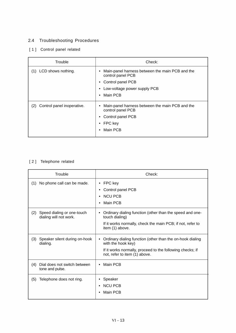
VI – 13
2.4 Troubleshooting Procedures
[ 1 ] Control panel related
Trouble Check:
Trouble Check:
(1) LCD shows nothing. • Main-panel harness between the main PCB and thecontrol panel PCB
• Control panel PCB
• Low-voltage power supply PCB
• Main PCB
(2) Control panel inoperative. • Main-panel harness between the main PCB and thecontrol panel PCB
• Control panel PCB
• FPC key
• Main PCB
(1) No phone call can be made. • FPC key
• Control panel PCB
• NCU PCB
• Main PCB
(2) Speed dialing or one-touchdialing will not work.
• Ordinary dialing function (other than the speed and one-touch dialing)
If it works normally, check the main PCB; if not, refer toitem (1) above.
(3) Speaker silent during on-hookdialing.
• Ordinary dialing function (other than the on-hook dialingwith the hook key)
If it works normally, proceed to the following checks; ifnot, refer to item (1) above.
(4) Dial does not switch betweentone and pulse.
(5) Telephone does not ring.
• Main PCB
• Speaker
• NCU PCB
• Main PCB
[ 2 ] Telephone related

VI – 14
[ 3 ] Communications related
[ 4 ] Paper/document feeding related
(1) No tone is transmitted. • Main PCB
• NCU PCB
Trouble Check:
Trouble Check:
(1) Neither “COPY: PRESSCOPY” nor “FAX: NO. &START” message appearsalthough documents are set.
• Sensors by using the maintenance-mode function No. 32.(Refer to Chapter V, Section 3.8.)
• Actuators of the document front and rear sensors
• Main PCB
(2) Document not fed. • ADF and its related sections
• Scanner motor and its harness
• Document feed rollers and their related gears
• Main PCB
(3) Document double feeding • ADF parts
• Nip-related parts
• Multi-purpose sheet feeder
• Drum unit
• Heat-fixing unit
• Gear drive unit
• Main PCB
(4) Recording paper not fed.
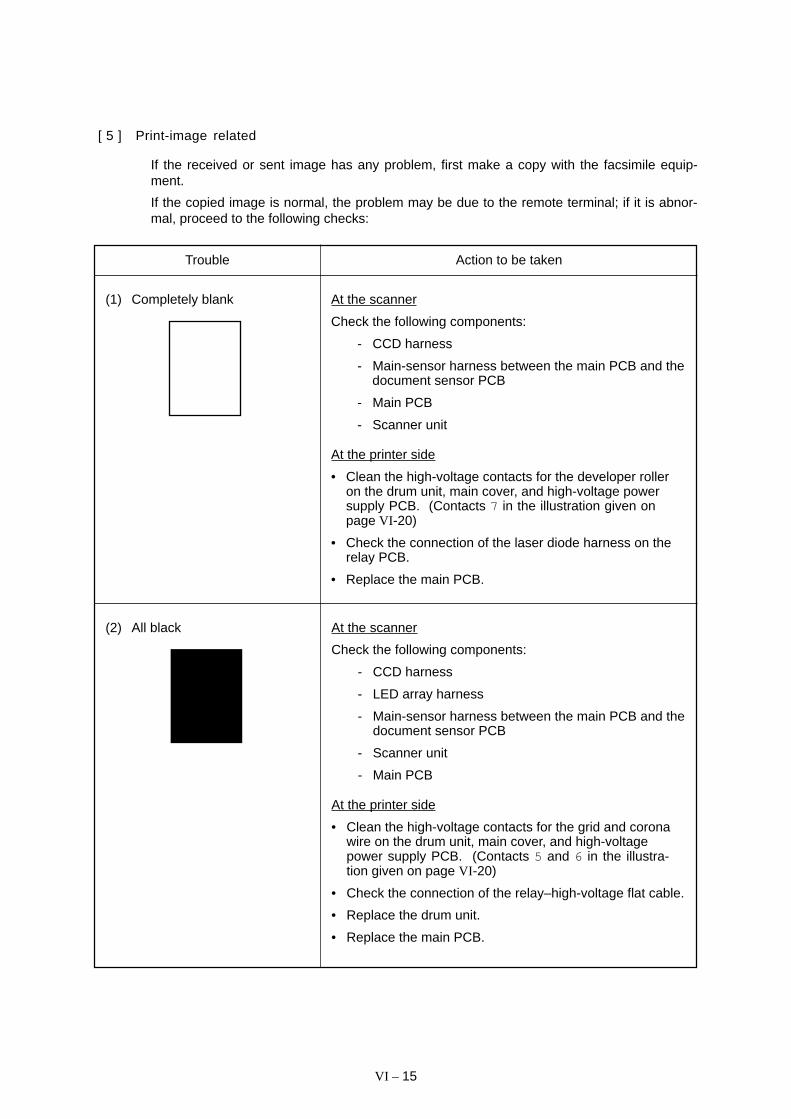
VI – 15
[ 5 ] Print-image related
If the received or sent image has any problem, first make a copy with the facsimile equip-ment.
If the copied image is normal, the problem may be due to the remote terminal; if it is abnor-mal, proceed to the following checks:
Trouble Action to be taken
(1) Completely blank At the scanner
Check the following components:
- CCD harness
- Main-sensor harness between the main PCB and thedocument sensor PCB
- Main PCB
- Scanner unit
At the printer side
• Clean the high-voltage contacts for the developer rolleron the drum unit, main cover, and high-voltage powersupply PCB. (Contacts 7 in the illustration given onpage VI -20)
• Check the connection of the laser diode harness on therelay PCB.
• Replace the main PCB.
(2) All black At the scanner
Check the following components:
- CCD harness
- LED array harness
- Main-sensor harness between the main PCB and thedocument sensor PCB
- Scanner unit
- Main PCB
At the printer side
• Clean the high-voltage contacts for the grid and coronawire on the drum unit, main cover, and high-voltagepower supply PCB. (Contacts 5 and 6 in the illustra-tion given on page VI -20)
• Check the connection of the relay–high-voltage flat cable.
• Replace the drum unit.
• Replace the main PCB.

VI – 16
Trouble Action to be taken
(3) Light At the scanner
Check the following components:
- Scanner unit
- Main PCB
At the printer side
• Check the setting position of the print density dial.
• Replace the toner cartridge with a new one and print 4 to5 pages. If the problem persists, proceed to the nextstep.
• Remove the toner cartridge and start printing. If printingtakes place, clean the toner sensor or replace the tonersensor PCB.
• Clean the high-voltage contacts for the transfer roller onthe drum unit, main cover, and high-voltage power supplyPCB. (Contacts 3 in the illustration given on page VI -20)
• Clean the high-voltage contacts for the developer rolleron the drum unit, main cover, and high-voltage powersupply PCB. (Contacts 7 in the illustration given onpage VI -20)
• Clean the grounding contacts on the drum unit, gear driveunit, and main cover. (Contacts 1 and 2 in the illustra-tion given on page VI -20)
• Check the connection of the relay–high-voltage flat cable.
• Check the connection between the relay PCB and themain PCB.
• Replace the drum unit.
• Replace the high-voltage power supply PCB.
• Replace the main PCB.
(4) Dark At the scanner
Check the following components:
- Scanner unit
- Main PCB
At the printer side
• Check the setting position of the print density dial.
• Slide the wire cleaner tab to clean the corona wire insidethe drum unit.
• Clean the high-voltage contacts for the grid and coronawire on the drum unit, main cover, and high-voltagepower supply PCB. (Contacts 5 and 6 in the illustrationgiven on page VI -20)
• Replace the drum unit.

VI – 17
Trouble Action to be taken
(5) Black and blurred verticalstripes
At the scanner
Check the following components:
- Scanner unit
- Mirrors on the scanner unit for stains
At the printer side
• Clean the paper path which may be contaminated withtoner.
• Slide the wire cleaner tab to clean the corona wire insidethe drum unit.
• Make sure that the wire cleaner tab is returned to itshome position.
• Replace the drum unit.
• Replace the heat-fixing unit.
(6) Black and blurred horizontalstripes
At the printer side
• If the horizontal stripes appear at 94-mm or 17-mmintervals, replace the drum unit.
• If they appear at 54-mm intervals, replace the heat-fixingunit.
(7) White vertical streaks At the scanner
Check the following components:
- Scanner unit
- Mirrors on the scanner unit for stains
At the printer side
• Clean the cover glass of the laser unit with a dry softcloth.
• Replace the drum unit.
(8) Dropout At the printer side
• Check the connection of the relay–high-voltage flat cable.
• Check the connection between the relay PCB and themain PCB.
• Replace the drum unit.
• Replace the high-voltage power supply PCB.

VI – 18
Trouble Action to be taken
(9) Faulty image registration(Leading edge of image startstoo late on paper)
At the printer side
• Instruct the user not to load paper exceeding the limitmark on the multi-purpose sheet feeder.
• Instruct the user to use the recommended types of paper.
• Replace the multi-purpose sheet feeder.
• Replace the gear drive unit.
(10) Image distortion or improperimage alignment
In communications
Check the following components:
- Error code displayed. (Refer to Section 1, “ERRORINDICATION” in this chapter.)
- NCU PCB
- Main PCB
At the scanner
Check the following components:
- Separator roller and its related sections
- Document feed rollers and their related gears
- Scanner motor and its harness
- Main PCB
At the printer side
• Check that the laser unit is secured with the screwswithout looseness.
• Check the connection of the polygon motor flat cable onthe relay PCB.
• Replace the laser unit.

VI – 19
Trouble Action to be taken
(11) Blurred at either side At the printer side
• Shake the toner cartridge. If the problem persists,replace it.
• Check that the equipment is placed on a flat surface.
• Shake the drum unit from left to right and front to back.
Print out test print out test print out test Print out test print oPrint out test print out test print out test Print out test print o Print out test print o
Print out test print out test print out test Print out test print oPrint out test print out test print out test Print out test print o Print out test print o
Print out test print out test print out test Print out test print oPrint out test print out test print out test Print out test print o Print out test print o
Print out test print out test print out test Print out test print oPrint out test print out test print out test Print out test print o Print out test print o
Print out test print out test print out test Print out test print oPrint out test print out test print out test Print out test print o Print out test print o
Print out test print out test print out test Print out test print oPrint out test print out test print out test Print out test print o Print out test print o
Print out test print out test print out test Print out test print oPrint out test print out test print out test Print out test print o Print out test print o
Print out test print out test print out test Print out test print oPrint out test print out test print out test Print out test print o Print out test print o
Print out test print out test print out test Print out test print oPrint out test print out test print out test Print out test print o Print out test print o
Print out test print out test print out test Print out test print oPrint out test print out test print out test Print out test print o Print out test print o
Print out test print out test print out test Print out test print oPrint out test print out test print out test Print out test print o Print out test print o
Print out test print out test print out test Print out test print oPrint out test print out test print out test Print out test print o Print out test print o
Print out test print out test print out test Print out test print oPrint out test print out test print out test Print out test print o Print out test print o
Print out test print out test print out test Print out test print o Print out test print out test print out test Print out test print oPrint out test print o
Print out test print out test print out test Print out test print o Print out test print out test print out test Print out test print oPrint out test print o
Print out test print out test print out test Print out test print o Print out test print out test print out test Print out test print oPrint out test print o
Print out test print out test print out test Print out test print o Print out test print out test print out test Print out test print oPrint out test print o
Print out test print out test print out test Print out test print o Print out test print out test print out test Print out test print oPrint out test print o
Print out test print out test print out test Print out test print o Print out test print out test print out test Print out test print oPrint out test print o
Print out test print out test print out test Print out test print o Print out test print out test print out test Print out test print oPrint out test print o
Print out test print out test print out test Print out test print o Print out test print out test print out test Print out test print oPrint out test print o
Print out test print out test print out test Print out test print o Print out test print out test print out test Print out test print oPrint out test print o
Print out test print out test print out test Print out test print o Print out test print out test print out test Print out test print oPrint out test print o
Print out test print out test print out test Print out test print o Print out test print out test print out test Print out test print oPrint out test print o
Print out test print out test print out test Print out test print o Print out test print out test print out test Print out test print oPrint out test print o
Print out test print out test print out test Print out test print o Print out test print out test print out test Print out test print oPrint out test print o
(12) Dirt back of paper At the printer side
• Replace the drum unit.
• Replace the heat-fixing unit.
(13) Poor fixing At the printer side
• Instruct the user to use paper of the recommendedweight (less than 36 lb./m2).
• Replace the heat-fixing unit.
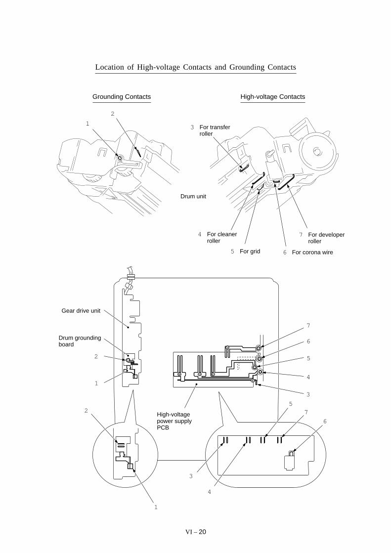
VI – 20
Location of High-voltage Contacts and Grounding Contacts
2
1
Gear drive unit
Drum groundingboard
2
1
3
4
57
6
3
4
5
6
7
High-voltagepower supplyPCB
High-voltage Contacts
6 For corona wire5 For grid
4 For cleanerroller
7 For developerroller
3 For transferroller
Grounding Contacts
1
2
Drum unit

FAX3550/8000PMFC4550/6550MC/7550MC
MFC9000/9500
APPENDICES
Circuit Diagrams
A. Main PCB
B. Relay PCB
C. Network Control Unit (NCU) PCB
D. Control Panel PCB
E. Power Supply PCB
Low-voltage power supplyHigh-voltage power supply
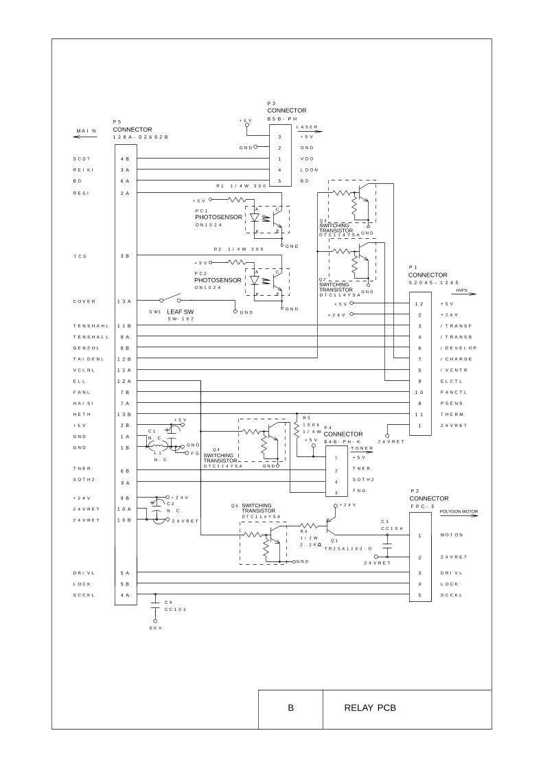
B RELAY PCB
G N D
C 2
N . C .
P 5
1 2 8 A - 0 2 6 S 2 B
P 1
5 2 0 4 5 - 1 2 4 5
1
3
2
1 2
2
4
6
7
1 0
2 A
+ 5 V
S O T H 2
2 4 V R E T
+ 5 V
+ 2 4 V
/ T R A N S B
/ D E V E L O P
/ C H A R G E
F A N C T L
R E S I
T C S
T E N S H A H L
V C L N L
E L L
+ 5 V
G N D
G N D
S O T H 2
D R I V L
3 / T R A N S F
5 / V C N T R
9 E L C T L
8 P S E N S
1 1 T H E R M
1 2 4 V R E T
1 M O T O N
3 D R I V L
4 L O C K
5 S C C K L
P 4
B 4 B - P H - K
P 2
F P C - 5
2
C 1
N . C .
S W 1
S W - 1 6 2
+ 5 V
+ 2 4 V
2 4 V R E T
+ 5 V
G N D+ 5 V
T N G
2 4 V R E T
R 1 1 / 4 W 3 0 0
R 2 1 / 4 W 3 0 0
3 B
1 3 A
1 1 B
8 A
8 B
1 2 B
7 B
7 A
1 3 B
1 1 A
1 2 A
2 B
1 A
1 B
6 B
9 B
1 0 A
1 0 B
5 A
5 B
4 A
C O V E R
T E N S H A L L
G E N Z O L
T A I D E N L
F A N L
H A I S I
H E T H
+ 2 4 V
2 4 V R E T
2 4 V R E T
L O C K
S C C K L
R 3
1 5 0 k
1 / 4 W
+ 2 4 V
9 A
C 3
C C 1 0 4
4
T N E RT N E R
C 4
C C 1 0 2
L 1
N . C
F G
S 0 V
2 4 V R E T
G N D
P C 1
O N 1 0 2 4
A
K E
C
+ 5 V
G N D
P C 2
O N 1 0 2 4
A
K E
C
+ 5 V
D T C 1 1 4 Y S A G N D
D T C 1 1 4 Y S AG N D
G N D
+ 2 4 V
T R 2 S A 1 2 8 3 - D
R 4
1 / 2 W
2 . 2 K
G N D
D T C 1 1 4 Y S A
D T C 1 1 4 Y S A
Q 3
Q 2
Q 1
Q 5
Q 4
B D 6 A
S C D T
R E I K I
4 B
3 A
2 G N D
3 + 5 V
1 V D O
4 L D O N
5 B D
P 3
B 5 B - P H+ 5 V
G N D
L A S E R
T O N E R
HVPS
M A I N
POLYGON MOTOR
CONNECTOR
CONNECTOR
PHOTOSENSOR
PHOTOSENSORCONNECTOR
SWITCHING TRANSISTOR
SWITCHING TRANSISTOR
SWITCHING TRANSISTOR
SWITCHING TRANSISTOR
CONNECTOR
CONNECTOR
LEAF SW

E POWER SUPPLY (120 V)Low-voltage power supply
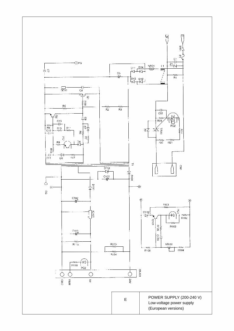
E POWER SUPPLY (200-240 V)Low-voltage power supply(European versions)

E POWER SUPPLY (200-240 V)Low-voltage power supply(Asian versions)
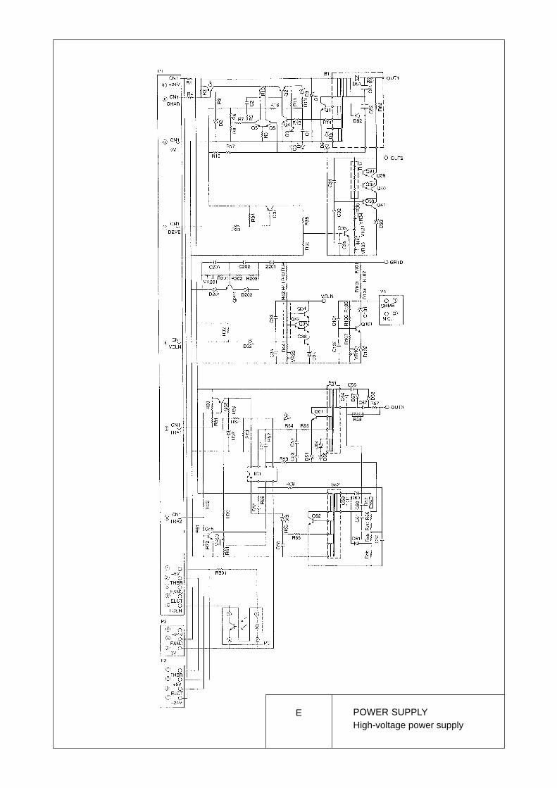
E POWER SUPPLYHigh-voltage power supply

R B
S H
C M P R A
C M P R B
C L K 2 4
C S I P
I P D 1
I P D 2
P 8 3
R V D D
P M 1
P M 2
P M 3
P M 4
C M P P A
C M P P B
S O L
D R I V E
V D O
H V T P
H V T N
H V C H
H V G Z
H V C L
E R A S E
E X V D
C B S O N
H T O
S E L I N
P R M I N T
F L T
S L C T
B U S Y
S T B
A C K
C T S
R T S
T X D
R X D
4 8
5 7
8 2 3 3
3 4
1 1 1
2 4
1 6 3 1 6 0
1 4 4
1 4 5
1 4 8
1 4 9
1 5 0
1 5 1
6 4 BH B U Y
2 1 DR O M 3
R S E N
F S E N
S E N 6
M C E
M R S T
S D O U T
S D I N
S M P C
A D L C
I P D 4
I P D 5
I P D 6
I P D 7
R B
S H
C L 2
C L 1
T R G
P A 2
7 1 C
5 5 C
3 2 B
3 2 A # 1
9 4
S E N 8
D 3
D 2
D 1
D 0
R D
H W R
W R
D A 0
A 1 9
A 1 8
A 1 7
A 1 6
A 1 5
D A 1 1
D A 1 0
D A 9
D A 8
D A 7
D A 6
D A 5
D A 4
D A 3
D A 2
D 1 5
S E N 5
S P O N
P 7 1
D 1 3
D 1 2
D 1 1
D 1 0
D 9
D 8
D 7
D 6
D 5
2 0 8
1 9 8
1 9 7
1 9 6
1 7 8
1 8 1
R I N G
T E L
S E N 2
P W M 3
A N 0
P W M 2
P W M 1
S E N 0
S E N 1
S E N 7
D P S
P L S
C M L
M I N T
C L K
U C A S
P 7 3
E E D A T
L C A S
R A S 3
R A S 2
R A S 1
R A S 0
R O M 1
R A M W R
R A M U W E
R X T
R E X T
R S T
E X T L
E X T L
1 1 2
6
1 2 4
1 3 3
6 7
6 6
1 7
1 6
1 3 0
# 1
R 2 5
1 . 5 K
+ 5 V
# 1
C6
3
X V D O2 6 A
1 7 9
D A 1
A 1 4
1 9 1
4
3
2
1
5
6
7
8
1
2
4
3
8
7
5
6
1 8 6
1 8 7
1 8 9
1 8 8
4
3
2
1
5
6
7
8
4
3
2
1
5
6
7
8
1 8 2
1 8 3
1 8 5
1 8 4
4
3
2
1
5
6
7
8
4
3
2
1
5
6
7
8
1 7 7
R A 1 0
R A 1 1
R A 3
A 1 2
A 1 3
C 2 6
C C 1 0 2
S 0 V
C 2 5
C C 1 0 4P S T 5 9 3
S 0 V
4
3
1
Q 8
1 9 5
1 9 2
R 1 1 4 1 0
1 1 8
1 1 7
X T 2
C 5 5C 5 6
C C 1 0 P
S 0 V
S 0 V
X T 1
C 3 2
1 5 p
R 3 8
2 2 0
C 3 3
1 5 p
R 5 0
0
R A M R D
7 2 CD A R E C
2 3 A , 2 3 B , 2 4 A , 2 4 C , 2 5 A
9
7
7 1 AP L S 7 3
7 2 A , 7 3 BC M L H 7 1
6 8
E E C K2 3 D
E S D2 3 D
R 1 2 0 1 0
R M W R2 3 A , 2 3 B , 2 4 A , 2 4 B , 2 5 A
8
R 1 1 6 1 0
R A M R D
7 2 D
D A S T7 2 C
D A S E N D
2 3 B , 2 4 A , 2 5 A
5
U C A S
2 3 A , 2 4 A , 2 4 C , 2 5 AC A S R 1 2 1 1 0
7 4
7 3 CM U T E 9 1
H S P L Y 9 0
7 4 C
7 3 B
7 6R I N G O
4 6 BM I N T 4 0
8 9T L O F7 2 A
C 17 7C 1
7 2 A
7 27 1 D
7 1 DD P S
E A T 9 5
7 2 D8 8P O L
4
2 1 B R O M C E 1 6 2
3
2 4 A , 2 5 AR A S 1 2
R A S 0 1
2 5 AR A S 2R A S 2
2 3 A , 2 4 C
R A S 3
S E N 3
1 4 1
A 2 0
9 37 4 B
T A D H
+ 5 V
D 4
1 6 8
R 1 9 1 0 R D1 6 7
1 6 6R 1 8 1 0
L W R2 6 A , 3 5 C , 4 5 B
2 1 B , 2 1 D , 2 6 A
3 5 C , 4 5 B
D 1 4
1 7 5
1 6 9
1 7 0
1 7 1
1 7 2
1 7 3
1 7 6
1 7 4
2 0 7
2 0 6
2 0 5
2 0 4
1 9 9
2 0 3
2 0 2
1 9 3
1 9 4
1 1 CR S
1 2 27 5 C
R N G
7 57 4 C
M S I L
V D D
G N D
C5
4
C1
9
C2
7
C2
9
S 0 V
G N D
G N D
G N D
G N D
G N D
G N D
G N D
G N D
G N D
V D D
V D D
V D D
V D D
V D D
V D D
V D D
V D D1 9 0
2 0 0
1 8 0
1 6 4
1 5 4
1 4 2
1 1 9
9 6
6 0
3 8
1 5
2 1
4 3
6 1
9 7
1 1 4
1 4 7
1 6 5
2 0 1
M C E
C S I P
3 9
5 53 4 C
4 7 A
T G
L E D
6 3
6 43 2 A
C L 2
C L 1
5 9
6 2
I P D 3
H O O K
5 63 5 B
5 8
5 4
5 3
5 2
5 1
5 0
4 9
4 73 6 C I P D 0
P D
R 2 4 1 . 5 K
1 3 2
S A 1 22 3 D
S M P C
5 5 B3 6C M P R B
5 5 B3 5C M P R A
S D O U T 4 63 3 D
P C L K 4 43 3 D
M R S T 4 14 7 A
P C L K
3 3 DS D I N 4 5
3 75 4 C
S O L
3 25 3 B
P M 4
3 15 3 B
P M 3
3 05 3 B
P M 2
2 95 3 B
P M 1
1 0 85 3 A
H T O
1 0 15 1 A
S C C K
1 0 25 1 A
D R I V
9 85 1 A
S C D T
9 95 1 A
L D O N
1 0 35 1 B
T E N H
1 0 45 1 B
T E N L
1 0 55 1 B
T A I D
1 0 65 1 C
G E N Z
1 0 75 1 C
V C L N
1 0 95 1 C
E L
S C NC L K
L D O N
1 4 6
1 5 76 4 A
F L T
1 5 86 4 A
P R M I N T
1 5 96 4 A
S E L I N
6 4 AS L C T1 5 6
6 4 AP P E1 5 5
6 4 AB U S Y1 5 3
6 4 AA C K1 5 2
6 4 BS T B1 6 1
H B U S Y
P P E
D C 0
1 4 3
6 4 B
D C B U S
D C 7
D C 6
D C 5
D C 4
D C 3
D C 2
D C 1
A B U S
P 8 4
R 3 3 2 2 K
R 2 3 1 . 5 K
R 2 2 B L M 1 1 A 2 0
R 2 1 1 . 5 K
R 2 0 B L M 1 1 A 2 0
1 3 5
1 3 8
1 3 7
1 3 9
1 4 0
1 3 6
+ 5 V
S 0 V
S 0 V
+ 5 V
C T S
R T S
R X
T X
M / L S E N
8
2
3
4
6
1
5
7
P 1
2 9 0 A - 8 8
8 P M O D U
E I N T 1
P B 5
1 2 65 1 D
C O V E R
B D
E R O M 2
P 7 0
P 7 4
P 7 5
P 7 61 2 7
A N 18 3
5 1 D
T N O R
A N 38 5
5 1 DH E T H
A N 28 4
L A S P1 1 0
5 1 BL A S P
R M 12 5
S O T H 2
2 65 5 B R M 2
R M 2
2 75 5 B R M 3
R M 3
2 85 5 B R M 4
R M 4
1 1 55 5 C P A 0
M T I 0
P B 6
S A M P
1 3 42 6 B P 8 5
X S E N
2 32 6 A
E X C S 1
E X I N T
1 1 35 1 A
L O C K
1 0 05 1 B
B D
1 3 15 1 C
H A I S I
1 2 15 1 D
R E S I
1 2 55 1 D
T C S
7 3 BT E L
R 2 6 2 2 K
2 22 6 A
E X C S
R 3 4
+ 5 V
+ 5 V
C L K 2 4R 2 0 1 4 2
3 5 C
1 2 3
R 1 9 8 2 2 K
P 7 2
E E C K+ 5 V
A M 8 1 67 0
7 85 5 C P A 1
M T I 1
1 2 02 2 D
P 7 7E E C K 2
6 9P W M 4
R 1 9 5
2 2 K
S E N 9C 2 8
C C 1 0 4
P A 36 5
5 1 CF A N
S 0 V
B A V D D
1 8
C 6 2
R V D D1 8
C 6 2
C C 1 0 4
R V D D6 6 B
S 0 V
R V D D
+ 5 B
R 3 2 2 2 K
C 6 1
C C 1 0 2
1 9
C 6 4
C C 1 0 4
1 0
S 0 V
R 5 3 1 0 0
R T C C O N
1 3C K 3 2
B A C L K
B A E N B
1 1
1 2
1 4C K 3 2 0 N
S 0 V
+ 5 B
R H 5 V A
V D D
G N D
Q 7
R 4 8
+ 5 B
2 0B K S L
C 3 0
C C 1 0 1
M 5 V
M 0 V
A V D D
A G N D
R 4 9
0
S 0 V
8 1
8 0
1 1 6
S 0 V
T S T 1
T S T 2
T S T 3
T S T 4
7 9
8 6
8 7
F G
R 5
S 0 V
F G
R 1 0 8
S 0 V S 0 V
8
7
6
5
2 5 A
R S
1 6 A , 2 6 A
3 4 C , 6 6 D
D B U S
3 2 B
3 2 B
3 2 B , 3 5 C
3 3 C
3 3 C
C - 0 0 1 R
C C 1 0 P
C2
3
C2
2
C2
1
C2
0
C2
4
S 0 V
S 0 V1 0 0 x 4
1 0 0 x 4
C C 1 0 4 x 5
2
0
1 2 9
+ 5 V
R 2 7
2 2 K
+ 5 V
R 1 9 6
2 2 K
S E N 49 2M T D I 1
1 2 85 6 C
V R C O N
*
1 0 0 X 4
N C
R 1 9 4
1 K
R 1 9 3
1 M
()
()
R 1 8 6
B L M 1 1 A 2 0
O U T
5 5 BR M 1
4
3
2
1
5
6
7
8
4
3
2
1
5
6
7
8
4
3
2
1
5
6
7
8
R A 1
R A 2
4
8
7
6
2
5
1
3
4
8
7
6
2
5
1
3
1 0 0 x 4
1 0 0 x 4
R 2 9 2 2 K
*
*
+ 5 V
*
R 1 9 7
2 2 K
*
*
M F C 3 5 5 0 , D S
R 5 4
2 0 0 L L 2 4 1
5 1 D
)(
)(
)(
R 2 1 2 1 . 5 K
R 2 1 1 1 . 5 K
B L M 1 1 A 2 0
R 2 1 3
4 5 5 0
03 5 5 0
0
A
B
1 2 3
C
D
1 2 3 5 6
A
B
C
D
6
4
4 5
A MAIN 1/8

P 3
D 1 5
1 1
1 31 2 B
# 9
1 2 B
D 1 0
D 1 1
D 1 2
4 2N C
2 2 1 2 3 1
C 1 0 2
C C 1 0 4
+ 5 V S 0 V
A 0
A 1
A 2
A 3
A 4
A 5
A 6
A 7
A 8
A 9
A 1 0
A 1 1
A 1 2
A 1 3
A 1 4
A 1 5
A 1 6
A 1 7
A 1 8A 1 9 1
1 0A 1
9A 2
8A 3
7A 4
6A 5
5A 6
4A 7
3A 8
4 1A 9
4 0A 1 0
3 9A 1 1
3 8A 1 2
3 7A 1 3
3 6A 1 4
3 5A 1 5
3 4A 1 6
3 3A 1 7
2A 1 8
D 9
D 0
D 1
D 2
D 3
D 4
D 5
D 6
D 7
D 8
D 1 3
D 1 4
A B U S
3 0
1 4
1 6
1 8
2 0
2 3
2 5
2 7
2 9
1 5
1 7
1 9
2 1
2 4
2 6
2 8
+ 5 V3 2
W O R D / B Y T E
C E
O ER D
D B U S
8 M R O M
V C C G G
N C
2 3
# 1 1
1 1
1 4 1 5 2 8
C 1 0 4
C C 1 0 4
+ 5 B S 0 V
A 0
A 1
A 2
A 3
A 4
A 5
A 6
A 7
A 8
A 9
1 0A 1
1 1A 2
1 2A 3
1 3A 4
1 6A 5
1 7A 6
1 8A 7
1 9A 8
2 0A 9
9A 1 0
D 0
D 1
D 2
D 3
D 4
D 5
D 6
D 7
A B U S
2
3
4
5
2 4
2 5
2 6
2 7
C A SU C A S
4 M D R A M
V C C G G
D 1 5
1 1
1 31 1 B
# 4
1 2 B
D 1 0
D 1 1
D 1 2
4 2N C
2 2 1 2 3 1
C 1 7
C C 1 0 4
+ 5 V S 0 V
A 0
A 1
A 2
A 3
A 4
A 5
A 6
A 7
A 8
A 9
A 1 0
A 1 1
A 1 2
A 1 3
A 1 4
A 1 5
A 1 6
A 1 7
A 1 8A 1 9 1
1 0A 1
9A 2
8A 3
7A 4
6A 5
5A 6
4A 7
3A 8
4 1A 9
4 0A 1 0
3 9A 1 1
3 8A 1 2
3 7A 1 3
3 6A 1 4
3 5A 1 5
3 4A 1 6
3 3A 1 7
2A 1 8
D 9
D 0
D 1
D 2
D 3
D 4
D 5
D 6
D 7
D 8
D 1 3
D 1 4
A B U S
3 0
1 4
1 6
1 8
2 0
2 3
2 5
2 7
2 9
1 5
1 7
1 9
2 1
2 4
2 6
2 8
+ 5 V3 2
W O R D / B Y T E
C E
O E
R O M C E
R D
D B U S
8 M R O M
V C C G G
1
6N C
WR M W R7
O E
R A S O R8V C C
R A S
D B U S
N C
2 8
# 1 2
2 1
1 4 1 5 2 8
C 1 0 9
C C 1 0 4
+ 5 B S 0 V
A 0
A 1
A 2
A 3
A 4
A 5
A 6
A 7
A 8
A 9
1 0A 1
1 1A 2
1 2A 3
1 3A 4
1 6A 5
1 7A 6
1 8A 7
1 9A 8
2 0A 9
9A 1 0
D 0
D 1
D 2
D 3
D 4
D 5
D 6
D 7
A B U S
2
3
4
5
2 4
2 5
2 6
2 7
C A SC A S
4 M D R A M
V C C G G
1
6N C
WR M W R7
O ER A M R D2 2
V C C
R A S
R 1 1 2
1 0R A S 0
R A S O R
8
2 3 B
D B U S
R A M R D2 2
2 3 A
1 1 B
1 1 B
1 1 B
1 1 B
1 1 B
1 1 B
D 0
D 1
D 2
D 3
D 4
D 5
D 6
D 7
D 8
D 9
D 1 0
D 1 1
D 1 2
D 1 3
D 1 4
D 1 5
1
2
3
4 5
6
7
8 1
2
3
4 5
6
7
8
+ 5 V
R 4 4
3 . 3 KS 0 V
E E C K
E S D
1 1 B
1 1 B , 1 5 BS D A
S C L
T E
V C CA 0
A 1
A 2
V S S
1 6 K
E E
# 3
S 0 V
1 5 C
E E C K 2
S 0 V
+ 5 V
S 0 V
E E
# 2
# 1 0
C 1 0 5
1 0 4
+ 5 B S 0 V
D 1
D 2
D 3
D 4
D 5
D 6
D 7
D 8
D 9
D 1 0
D 1 1
D 1 2
D 1 3
D 1 4
D 1 5
2D 0
3D 1
4D 2
5D 3
7D 4
8D 5
9D 6
1 0D 7
3 1D 8
3 2D 9
3 3D 1 0
3 4D 1 1
3 6D 1 2
3 7D 1 3
3 8D 1 4
A 0
A 1
A 2
D B U S
2 6
1 6
1 7
1 8
1 9
2 2
2 3
2 4
2 5
D R A M
4 061 3 5 2 12 0
G G GV C CV C C
D 1 5D 1 6
3 9
A 3
A 4
A 5
A 6
A 7
A 8 R
1 1 B2 3
1 1 B1 3
1 1 B2 7
N C3 0
R A S
L W
O E
C A S
2 M
1 4
R 1 1 3
1 0 R A S 0
R M W R
R A M R D
U C A S
1 1 B
3 11 1 B
# 1 5
1 6N C
C 1 0 7
C C 1 0 4
+ 5 B S 0 V
D 0 1
D 0 2
D 0 3
D 0 4
D 0 5
D 0 6
D 0 7
D 0 8
D 0 9
D 0 1 0
D 0 1 1
D 0 1 2
D 0 1 3
D 0 1 4
D 0 1 5
2D 0
3D 1
4D 2
5D 3
7D 4
8D 5
9D 6
1 0D 7
3 3D 8
3 4D 9
3 5D 1 0
3 6D 1 1
3 8D 1 2
3 9D 1 3
4 0D 1 4
A 0
A 1
A 2
D B U S
2 8
1 8
1 9
2 0
2 3
2 4
2 5
2 6
2 7
D R A M
3 712 1 2 2 4 26
G G GV C CV C C
D 1 5 4 1
A 3
A 4
A 5
A 6
A 7
A 8
1 1 B1 3
1 1 B2 9
1 1 B3 0
R A S
W E
O E
U C A S
L C A S1 6 M
1 4
R 1 1 7
1 0
R A S 0
R M W R
R A M R D
U C A S
C A S
1 7 A 1
A 2
A 3
A 4
A 5
A 6
A 7
A 8
A 9
A 1 0
A 1
A 2
A 3
A 4
A 5
A 6
A 7
A 8
A B U S
N C1 2
N C2 1
D H B P B 3 0
1 7
2
1 3
2 2
X S E N
1
R S
1 6E X I N T
2 7R E S I
A 9
D 7
2 1
D 0
D 1
D 2
D 3
D 4
D 5
D 6
D B U S
A 5
1 2
2 0
1 0
2 8
1 4
1 5
2 9
3 0
A 1 .
A 2
A 3
A 4
A B U S
2 4
9
8
2 3
7
C 6 0
1 0 4
C 5
1 0
/ 1 0 V
1 1
2 5
2 6
3
4
1 8
1 9
P 2
D H B P B 4 0
1 5
1 6
R 1 1 1
R 1 1 0
R 1 0 9
R A S 1
R A S 2
R A S 3
1 1 B
1 1 B
1 7R M W R
1 8R A M R D
1 9U C A S
2 0C A S
D 1 54 0
2 5
3 2
3 3
3 4
3 5
3 6
3 7
3 8
3 9
D 0
D 7
D 8
D 9
D 1 0
D 1 1
D 1 2
D 1 3
D 1 4
D B U S
A 1
A 1 01 4
5
6
7
8
9
1 0
1 1
1 2
1 3
A 2
A 3
A 4
A 5
A 6
A 7
A 8
A 9
A B U S
D 63 1
D 53 0
D 42 9
D 32 8
D 22 7
D 12 6
+ 5 B
S 0 V
C 1 0 3
C C 1 0 4
C 9
1 0 0
/ 1 0 V
3
4
2 3
1
2
2 1
2 2
L W R
R D
E X C S
B D
X V D O
S 0 V
5
6
S 0 V
+ 5 V
R O M 3
1 1 B
1 1 B
1 1 B
1 1 B
1 1 B
1 1 B
1 1 C
1 5 B
1 2 B
1 2 B
1 5 B
5 1 D
5 1 B
1 5 B
1 4 B
+ 5 V + 5 V
R 4 6
2 2 K
R 4 7
2 2 K
A 0
A 1
A 2
V S S S D A
S C L
T E
V C C
D 0 0
N C
1 5
R 1 7 5 0
( )
R A S 11 1 B
R 1 7 2
A 4
* R 1 7 9
0
A B U S
R 1 8 0 0
A 5
( )R 1 8 1
* R 1 7 6
+ 5 B
S O V
A 4( )( ) * R 1 7 8
R 1 7 7
0
A 5
A 1 0
R 1 8 2
2 4
2 91 1 B
C A S
*
*
*
*
*
*
*
*
*
*
*
*
*
*
*
*
*
*
*
*
*
N C1 5
U C A S
A
B
1 2 3
C
D
1 2 3 5 6
A
B
C
D
6
4
4 5
DS MODELS
A MAIN 2/8
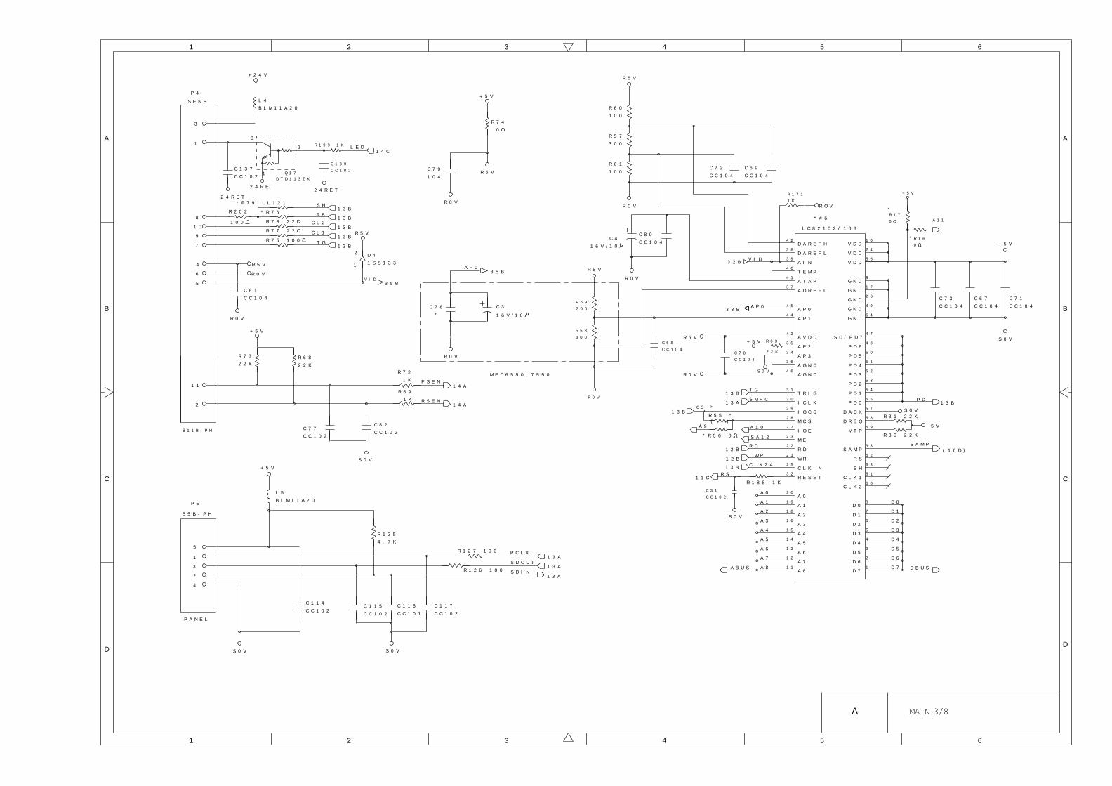
D A R E F H V D D
V D D
V D D
T E M P
A T A P
A P 2
A P 3
T R I G
M T P
S D / P D 7
P D 6
P D 5
P D 1
D 0
D 1
D 2
D 3
D 4
D 5
D 6
D 7
A 0
A 2
A 3
A 4
A G N D
A G N D
A V D D
4 2
4 0
4 1
3 5
3 4
3 1
4 3
1 0
2 4
5 6
9
1 7
2 6
4 9
6 4
4 7
4 8
5 0
5 4
5 9
3 6
4 6
2 0
1 8
1 6
1 5
8
7
6
5
4
3
2
1
R 0 V
R 5 V
R 0 V
* # 6
1 1
1 2
A 5
A 6
A 7
A 8
1 4
1 3
1 9A 1
P D 4
P D 3
P D 2
5 1
5 2
5 3
S A M P
R S
3 3
6 2
S H
C L K 1
6 3
6 1
C L K 26 0
P D 05 5
D A C K5 7
D R E Q5 8
+ 5 V
3 0
2 9
2 8
2 7
2 3
2 2
2 1
2 5
3 2
I C L K
I O C S
M C S
I O E
M E
R D
W R
C L K I N
R E S E T
3 9D A R E F L
A I N
3 8
4 5
4 4A P 0
A P 1
3 7A D R E F L
3 2 B
R 0 V
C 7 1
C C 1 0 4
C 7 3
C C 1 0 4
C 7 0
C C 1 0 4
C 8 0
C C 1 0 4
1 0
R 5 9
2 0 0
R 5 8
3 0 0
C 6 9
C C 1 0 4
C 7 2
C C 1 0 4
A 8
A 5
A 6
A 7
D 7
D 0
D 1
D 2
D 3
D 4
D 5
D 6
G N D
S 0 V
A 4
A 0
A 2
A 3
A 1
R 5 V
L C 8 2 1 0 2 / 1 0 3
C 6 7
C C 1 0 4
G N D
G N D
G N D
G N D
D B U S
S 0 V
+ 5 V
R 3 1 2 2 K
R 3 0 2 2 K
1 3 BP D
A B U S
S 0 V
R S1 1 C
C L K 2 4
L W R
T G
A P 0
A 1 0
1 3 B
1 2 B
1 3 B
A 9
* R 5 6 0
R 5 5 *
C S I P1 3 B
R D1 2 B
S M P C1 3 A
S 0 V
+ 5 V R 6 3
S A 1 2
3 3 B1 6 V /
R 0 V
R 6 0
1 0 0
R 6 1
1 0 0
R 5 7
3 0 0
R 5 V
V I D
R 7 4
0
+ 5 V
R 5 V
R 0 V
C 7 9
1 0 4
1 6 V /
C 4
1 0
C 3C 7 8
*
R 0 V
A P 03 5 B
S E N S
P 4
+ 2 4 V
L 4
B L M 1 1 A 2 0
3
3
2
1
2 4 R E T
1L E D
1 4 C
Q 1 7D T D 1 1 3 Z K
R 7 5 1 0 01 3 B
* R 7 9 L L 1 2 11 3 B
* R 7 61 3 B
R 7 8 2 21 3 B
R 7 7 2 21 3 B
8
1 0
9
7
S H
R B
C L 2
C L 1
T G
R 5 V
R 0 V
3 5 B
R 5 V
4
6
5
1 1
2
+ 5 V
R 7 3
2 2 KR 6 8
2 2 K
C 7 7
C C 1 0 2
C 8 2
C C 1 0 2
S 0 V
R 7 2
1 K
R 6 9
1 K
F S E N
R S E N
1 4 A
1 4 A
5
1
3
2
4
B 5 B - P H
P 5
+ 5 V
L 5
B L M 1 1 A 2 0
C 1 1 4
C C 1 0 2
S 0 V
C 1 1 5
C C 1 0 2
C 1 1 6
C C 1 0 1
C 1 1 7
C C 1 0 2
R 1 2 5
4 . 7 K
S 0 V
R 1 2 6 1 0 0
R 1 2 7 1 0 0 P C L K
S D O U T
S D I N
1 3 A
1 3 A
1 3 A
P A N E L
2
1
D 4
1 S S 1 3 3
V I D
B 1 1 B - P H
C 3 1
C C 1 0 2
C 6 8
C C 1 0 4 2 2 K
+ 5 V
A 1 1
R 1 7 1
1 K
R 1 7
0
( )
S A M P( 1 6 D )
R 1 6
0
R 1 8 8 1 K
R O V
C 8 1
C C 1 0 4
R 0 V
2 4 R E T
C 1 3 7
C C 1 0 2
2 4 R E T
R 1 9 9 1 K
C 1 3 9
C C 1 0 2
*
*
M F C 6 5 5 0 , 7 5 5 0
R 2 0 2
1 0 0
A
B
1 2 3
C
D
1 2 3 5 6
A
B
C
D
6
4
4 5
A MAIN 3/8

A V D D
R X D
V D D 1
V D D 2
V D D 3
D G N D 1
V A A 1
V A A 2 L
S R 4 I N
S R 3 O U T
S A 1 C L K
S R 3 I N
T X D A T
I A 1 C L K
T S T R O B E
T M O D E
S R 1 I O
R M O D E
/ R E S E T
R S 1
D 0
R S 0
Y C L K
X C L K
D G N D 2
D G N D 3
G P O 0
2 5
3 5
4 5
8 2
8 3
8 7
9 0
8 6
2 3
8 8
1 8
7 2
4 7
7 1
6
5 8
7 7
1 6
6 7
9 3
9 2
9 6
9 9
1 0 0
1 4
1 3
1 2
1 1
1 0
9
8
7
5
4
2
1
7 8
6 8
5 3
5 2
7 6
7 5
5 5
5 6
3 0
4 3
8 4
6 1
6 6
5 9
6 0
2 1
9 7
8 1
S 0 V
R F X 1 4 4
+ 5 V
C 7
1 0 V
/ 1 0
C L K I N
I A C L K
4 8
5 07 3
7 4
C 6
1 0 V
/ 1 0
C 8 3
C C 1 0 4
C 8 4
C C 1 0 4
R 1 6 9
2 2 K
R 6 5
0
R 6 4
P 1 7
S H O R T - 2
# 7
R 6 7
R 6 6
0
R 7 1
4 . 7 K
+ 5 VS O V
L 6
0
M 5 VM O V
A R E F
R 1 6 6
2 7 K
R 1 0 4
5 6 K
C 8 5
C C 1 0 4
-
+
# 8
K I 3 2 4
C 1 0 0
C C 1 0 4R 1 0 6
6 8 K
C 9 9
C C 1 0 2
R 1 0 5 6 8 K
R 6 2
0
1
2
3
-
+
# 8
K I 3 2 4
6
5
7
R 9 8 6 8 K
/ C T S
D C L K
/ R L S D
/ R T S
T X D
D 1
D 2
D 3
D 4
D 5
D 6
D 7
C 7 6
C C 1 0 4
C 7 5
C C 1 0 4
+ 5 V
R S 2
R S 3
R S 4
/ I R Q 2
/ I R Q 1
/ R E A D
/ C S
3
1 5/ W R I T E
8 0
D G N D 4
D G N D 5
D G N D A 1
D G N D A 2
D G N D A 3
E Y E S Y N C
E Y E C L K8 5
E Y E X Y8 9
X T L I
X T L O
M 0 V
S 0 V
R 1 2 3
2 2 K
A 1
A 5
R D
L W R
M C E
N C
N C
A 4
A 3
A 2
T R E S E T2 0
2 4
R X O U T
1 9
S R 4 O U T
1 7
7 9
3 6
/ P O R
4 6/ S L E E P
/ O H
/ T A L K
R I N
T X A 1
T X A 2
S P K R
2 6
3 8
2 8
2 9
4 4
V R E F
V C
G P I 0
4 0
3 9
9 5
9 8
5 4
5 7
7 0
6 9
6 5
6 4
6 3
6 2
9 4
G P I 1
G P I 2
G P I 3
G P I 4
G P I 5
G P I 6
G P I 7
G P O 1
G P O 2
G P O 3
G P O 4
G P O 5
G P O 6
G P O 7
/ E N 8 5
A G N D 13 7
2 7
A G N D 2
S 0 VS 0 V
C 5 9
1 0 p F
C 5 8
1 0 p F
C 5 7
3 3 p F
L 2
2 . 2 U H
X T 3
+ 5 V
M 0 V
R 1 6 8
0
C 6 5
C C 1 0 4
C 1 3 5
1 0 0 F / 1 0 V
G P I 0
G P I 1
G P I 2
M 0 V
R 9 9
5 6 KC 9 4
C C 1 0 4
A R E F
R 1 6 5
6 8 K
C 9 6
C C 1 0 4
M 0 V
R 9 7
4 . 7 K
R 1 0 7
4 . 7 K
S 0 VR 1 6 7
2 2 0 K
R 7 0
4 . 7 K
M 5 V
M 0 V
A R E F
C 8 6
C C 1 0 4
R 5 1
1 0 0
* *
*
* *
+ 5 V
G P I 0
G P I 1
G P I 2
M S L
V O L 1
V O L 2
M R S T
D B U S
M I N T
A B U S
S 0 V
7 4 C
7 4 B
7 4 B
7 4 C
R R N G
R I N
S P O N
S 0 V
T X O
M 0 V
D 9
H Z 5 . 1 B
*
+ 5 V
*S O V
4 4 C
4 4 C
4 4 C7 5 C
7 5 D
7 4 B
4 5 C
4 5 C
4 5 C
1 3 A
1 2 B
1 2 B
1 1 B
1 3 A
A
B
1 2 3
C
D
1 2 3 5 6
A
B
C
D
6
4
4 5
A MAIN 4/8

32
1
D T C 1 1 4 Y KQ 1 3
Q 1 2
32
1
D T C 1 1 4 Y KQ 1 4
32
1
D T C 1 1 4 Y KQ 1 5
32
1
D T C 1 1 4 Y KQ 9
Q 1 0
+ 2 4 V R E T
F A N
E L
V C L N
G E N Z
T A I D
T E N L
T E N H
1 4 B
1 4 B
1 4 B
1 4 B
1 4 B
1 4 B
1 4 B
R 8 5
1 . 5 K
C 3 6
C C 1 0 1
S 0 V
L O C K
+ 5 V
S 0 V
C 3 4
C C 1 0 3
3
1
2
L A S P
L D O N1 4 B
1 5 B
Q 1 1
D T A 1 1 4 Y K
R 8 4
2 2 KB D
+ 5 V
C 8 7
C C 1 0 1
S 0 V
1 5 A
S C D T
S 0 V
C 8 8
1 4 B
+ 2 4 V
+ 5 V
T E N S H A H L
T E N S H A L L
T A I D E N L
G E N Z O L
V C L N L
E L L
F A N L
D R I V L
S C C K L
9 B
2 B
5 B
4 A
5 A
4 B
3 A
6 A
1 1 B
8 A
1 2 B
8 B
1 1 A
1 2 A
7 B
2 4 R E T
S 0 V
R 8 6
1 0 K F
R 1 9 1
1 0 K F
C 1 3 8
C C 1 0 2
S 0 V
M 0 V
S 0 V
C 3 5
C C 1 0 1R 3 7
1 M
S 0 V
S O T H 2
T N O R1 5 A
1 5 A
1 5 A
1 5 A , 2 6 A
R 4 0
1 K
R 3 9
2 2 K
R 4 1
2 2 K
R 4 2
2 2 K
R 4 3
1 K
+ 5 V
1 B
1 A
1 0 B
1 0 A
1 3 B
6 B
1 3 A
3 B
2 A
7 A
S 0 V
5
4
2
3
1
U M G 5 N
Q 1
D R I V
S C C K1 4 A
1 4 A
1 5 A
32
1
D T C 1 1 4 Y K
P 1 3 2 6 P I N
C H U K E IP 1 3
1 5 A , 2 6 A
R 8 3
1 0 0
H A I S I
R E S I
T C S
C O V E R
R 4 5
B L M 1 1 A 2 0
3
2
1
D T C 1 1 4 Y K
1 5 B
1 3 A
3
4
1
5
6
2G 4 D 4
D 1G 1
D 2G 2
D 3G 3
S 1
S 2
R M 4
3
5
7
9
1
1 0
A
A B
B
B B
R M 1
R M 3
R M 2
R 1 4 3
R 1 4 0
R 1 4 1
R 1 3 9
C 1 0
3 5 V / 4 7 0
1M T I 0
4
5
U M G 5 N
Q 2
R 1 5 2
4 7 0 F
R 1 5 3
1 K F
S 0 V
R 1 4 5
2 4 0 F
R 1 4 6
4 . 3 K F+ 5 V
2 4 R E T1 3 A
1 3 A
R 1 4 4
2 . 2 K
R 1 5 0
2 . 2 K
C M P R A
C M P R B
# 2 1
P C 3 9 3
1
7
2
3
6
5
C 1 2 7
C C 1 0 3
C 1 1 8
C C 1 0 3
R 1 4 2
1 0 0
R 1 4 9
1 0 0
R 4
0 . 4 7
R 3
0 . 4 71 / 2 W1 / 2 W
4 A K 2 9
# 1 7
2 4 R E T
+ 2 4 V
B 6 B - P H
P 1 0
1 5 B
1 5 B
1 5 B
2
4
6
82 4 R E T
1 5 B3M T I 1
2
2 4 R E T
1 4 AS O L
1
2
+ 2 4 V
1 P 8B 2 B - P H
2
3
2 4 R E T
D T D G 2 3 Y P
Q 2 0
1 5 CV R C O N
1
2
+ 2 4 V
1 P 1 8B 2 B - P H
2
3
2 4 R E T
D T D G 2 3 Y P
Q 2 4
2 4 R E T
1
2
P 1 1
B 2 B P HS 0 V
C 1 2 5
C C 1 0 1
R 1 3 2
B L M 1 1 A 2 0
R 1 2 8
1 K
+ 5 V
H O O K
6
2
5
1
3
4
0 4
V C C V C C
C / R
0 1
0 2
0 3
I N 1
I N 2
I N 3
I N 4
I 0
I 1
V r e f
V m A
V m B
R s B
# 1 6
V s A
R s A
V s B
L G P G
1 4 A
M T D I 1
2 2
1 4 A1 4 AP M 1 6
1 4 A1 4 AP M 3 5
1 4 AP M 2 2 3
2 4 R E T
+ 5 V
B 6 B - P H
P 9
+ 5 V
R 1 2 2
1 8 KN C
N C
N C
N C
N C
+ 2 4 V
R 2
0 . 6 2
1 W
R 1
0 . 6 2
1 W
2 4 R E T
9
1 1
1 5
1 9
8
2 0
3
1 0
2 6
1 8
2 17
+ 5 V
C 1 1 1
1 0 4
S 0 V
4
2 4
2
2 7
2 5
1 2
1 4
1 6
1 7
C 1 1 0
3 3 2
1 5 B1 5 B
H T O N
H E T H
R 1 5 7
1 . 8 K F
R 1 4 7
1 K F
+ 5 V
S 0 V
3
2
1
5
6
7
+ 5 V
S 0 V
C 1 2 6
C C 1 0 4
R 1 4 8
1 . 5 K
+ 5 V
Q 2 1
2 4 R E T
S 0 V
+ 2 4 V
+ 5 V 4
5
3
2
1
P 7
B 5 B - E H
S 0 V
L V P S
P M O T
S O L H O O K
+ 5 V
+ 5 V
# 1 9
P C 3 9 3
1 4 A
5 1 D
S 0 V
2 4 R E T
M T D 2 0 0 3
R 1 7 0
7 5 K
1 0 x 4
P M 4
M S I L
# 2 1
P C
3 9 3
+ 5 V
C 1 1 9
C C 1 0 4
8
4
B L U E
R E D
F A N 2
W H I T E
2 4 R E T1 1 3
C 1 3 6
C C 1 0 4
8
4
C 1 0 6
C C 1 0 4
R 1 9 2
4 . 7 K
9 A
B L A C K
+-
C 9 5
C C 1 0 2
C 8 9
C C 1 0 2
S 0 V
H E T H1 5 A , 5 3 B
R 0 V
C 1 4 5
2 4 R E T
2 4 R E T
C 1 1 2
2 4 R E T
C 1 4 4 + 5 V
R 2 1 0
()
R 2 0 3
B L M 1 1 A 2 0
A
B
1 2 3
C
D
1 2 3 5 6
A
B
C
D
6
4
4 5
+
-
+
-
+-
A MAIN 5/8

+ 5 v
S 0 V
+ 5 B
R V D D
S 0 V
+ 5 V
D 3
M A 7 0 0
C 2
5 . 5 V
4 7 3 F
C 1
1 0 V 1 0 0
R 1 3
0 L 1
0
R 1 2
1 K
1 01 4 C
- A C K
1 11 4 C
B U S Y
1 21 4 B
P P E
1 31 4 B
S L C T
3 21 4 B
F L T
3 11 4 B
P R M I N T
3 61 4 B
S E L I N
1 41 4 B
H B U Y
11 4 C
S T B
D C 08 1
3 D C 17 2
6 3
8 1
6 3
7 2
8 D C 6
81
9 D C 75 4
6 D C 48 1
7 D C 57 2
4 D C 26 3
5 D C 35 4
22
63
54
81
54
81
72
63
54
63
72
C3
7
5 4
C C 1 0 1 x 1 6
1 4 CD C B U S
2
1 6
1 7
1 9
2 0
2 1
2 2
2 3
2 4
2 5
2 6
2 7
2 8
2 9
3 0
5 7 L E 4 0 3 6 0
1 8
2 . 2 K x 4 2 . 2 K x 4
R 7 1 5 0
R 6 1 5 0
R 8 1 5 0
R A 4
1 . 0 K x 4R A 6 R A 8
S 0 V
+ 5 V
P 1 5
R A 9
1 0 0 x 4
1 0 0 x 4
R A 7
1 0 0 x 4
R A 5
C5
3
C5
2
C5
1
C5
0
C4
9
C4
8
C4
7
C4
6
CC
47
1
C4
2
C4
4
C4
3
C4
5
C4
1
C4
0
C3
9
C3
8
S 0 V
1
2
1 6 A
-
-
Q 6
S O V
C 1 8
C C 1 0 4
R 1 5
1 K
R S
R 1 1
3 3 K
Q 5
2 S A 1 3 6 4
Q 4
+ 5 V
D 2
1 S S 1 3 3
R 1 4
0
S 0 V
C 1 4 2
C C 1 0 4
S 0 V
P 1 4
B 2 B - P H
S 0 V
D 1
1 S S 1 3 3
+ 2 4 V
R 9
1 0 K
R 1 0
4 . 3 K
D T C 1 2 4 E K
2 S A 1 3 6 4
F A X 3 5 5 0 , D S
M F C 4 5 5 0 , D S
M F C 4 5 5 0 , 6 5 5 0 , 7 5 5 0
M F C 6 5 5 0
M F C 7 5 5 0R 2 0 5
4 . 7 K
-
+
T A 7 5 S 0 1 F
R 2 0 9
1 0 K F
4
3
1
S O V
R 2 0 7
1 8 K
+ 5 V
R 2 0 8 3 6 K
R 2 0 6
1 0 K F
+ 5 V
C 1 4 1
C C 1 0 4
S 0 V
Q 3
R H 5 R 4 7
1
2
G N D
O U T
V D D
C 1 6
C C 1 0 1
# 2 35 2
+ 5 V
* * *
N C
# 2 3
A
B
1 2 3
C
D
1 2 3 5 6
A
B
C
D
6
4
4 5
A MAIN 6/8

R 2 0 0
+ 5 V
1
2
S P
B 2 B - P H
B L A C K
L 7 B L M 1 1 A 2 0
L 8 B L M 1 1 A 2 0
C 1 3 0
C C 1 0 3 B
S 0 V
C 1 5
1 0 V 1 0 0
M 0 V
R 1 5 9
5 1 K
M 0 V
R I N G O
C
1
0
C N T
M 0 V
R N G
7 4 H C 4 0 5 3
R 1 3 6 0
R 1 3 5 0
C 1 2 8
C C 1 0 4
R 1 6 1
C 1 3 2
C C 1 0 4 R 1 5 1 K
3 . 3 K
R 1 5 6
6 8 0R 1 5 5
2 2 0
R 1 5 4
1 . 5 K
3
54
1 2 A
1 1 A
8
1
7
5
2
3
6 4
V + G N D
O U T
G A I N
G A I N
+ I N
- I N
# 2 2
C 1 4
1 0 V / 1 0 0
M 0 V
P 1 6
S 0 V
3
1
2
3
1
2
M 0 V
M 0 V
Q 2 3
Q 2 2
D T C 1 1 4 Y KV O L 1
V O L 24 4 C
4 4 C
D T C
1 1 4 Y K
9
# 1 4
R 1 3 0
1 0 0 K
C
1
0
C N T
2
C N T
# 1 8
T C 4 S 6 6 F
T L S L
7 1 B
1 4
1 3
1 2
1 1 AT E L
7 4 H C 4 0 5 3 - A
1
0
1
2C
# 1 4
1 5
7 1 BR L 1
R L 2
# 1 4
7 4 H C 4 0 5 3 - A
R L T L
1 1 A
0
C
1C N T
4
M U T E
1 1
1
R 1 3 4
S 0 V
D A R E C
1 1 B
1 1 A
1 1 B
1 1 A
1 1 B
1 5
D P S
E A T
R 8 2
1 5 0 K
+ 5 V
1 1 A
P O L
P 6
B 2 0 B - P H
# 1 8
T C 4 S 6 6 F
M 0 V
+ 5 V
5
3
M 5 V
M 0 V
# 1 4
7 4 H C 4 0 5 3
M 0 V
6 7 8
1 6
C 9 8
C C 5 0 C 1 0 4
C 1 3 3
C C 1 0 4
C M L H
N J M 3 8 6
U M C 4 N
M 0 V
S P O N
+ 5 V
C 1 3 1
C C 1 0 4
* R 1 5 8
5 1 K
1 6 V / 1 0 F
C 1 3
# 2 0
*
R 1 3 7
4 . 7 K
# 1 3
R 1 3 8 # 1 3
1 0
0 1 2
C
0
1
1 5
1 0M S L
1
2
C
1
0
C N T
4
9
T A D H
5
3
4
1
3
2
7
8
6
5
V +
A + i
A - i
B + i
B - i
G N D
A - O
B - O
N J M 2 0 7 3
-
+# 8
K I 3 2 4
R 9 1 5 6 K
C 9 0
R 9 2 1 0 K9
1 0
8
1 1 B
7 1 B
C 9 3
C C 8 2 2
D 1 1 1 S S 1 3 3
C 9 2 6 8 1
-
+
R 9 3 6 8 KR 9 4
1 0 0 K1 3
1 4
1 2# 8
K I 3 2 4
C 9 1 C C 1 0 4
R 1 8 9
1 0 K
2 4 V
T L S L
R L 1
S 0 V
7 3 B
7 3 C
7 3 C
9
5
6
7
1 1
1
R 9 5 1 . 5 K
R 9 6
4 . 7 K
M 0 V
R 1 0 0
0
R 1 0 1
2
31
DG
S
A R E F
C 1 0 1
R 1 0 3
1 1 A
1 1 A
1 1 B
C 1 2 2
C C 1 0 3 B
C 1 2 1
C C 1 0 3 B
S 0 V
R 8 0
2 2 K
R 8 1
1 K
+ 5 V
R 8 7 1 KP L S
1 1 B
Q 1 8
D T C 1 1 4 Y K
2 4 R E T
C M L H2
1
3
4
2
3
8C M L L
1 2
1 0
+ 5 V
+ 2 4 VN C U 1
A D L C
R L 2
1 6
D A S T
R 1 9 0
C 1 2 4
S 0 V
1 8
1 7
1 9
2 0
1 3
1 4
M 5 V
M 0 V
# 1 3
7 4 H C 4 0 5 3
+ 2 4 V
# 8
K I 3 2 4
8
1 6 4
1 1
C 1 2 9
C C 1 0 4
6 7
T L O F
C 1
4 6 C
Q 1 9
2 S K 2 0 8
U S V e r
1 1 AD A S E N D
R 8 9
C 1 2 3
S 0 V
# 1 3
H S P L Y
C
1
1 4
1 1
1 2
1 3
4 1 B
4 1 B
7 6 C
4 3 B
7 5 B
S P A M P
Q 2 5
3
2
1
4
5
+ 2 4 V
R 1 3 3 0
R 1 8 5 1 . 5 K
D 7
U D Z 9 . 1 B
R 8 8+ 2 4 V
D 1 0 1 S S 1 3 3A C
R 9 0
1 K
1 / 1 0 W
M 0 V
M O V
T X O
C
A
P R I N G
R I N
S P A M P*
*
*
*
*
*
M F C 6 5 5 0 , 7 5 5 0
*
*
*
*
*
**
C 1 4 0
M O V
*
*
*
C 1 4 3
M 0 V
*
*
R 2 0 4*
*R 1 6 0
*
*
1 2 A
4 4 C
1 1 A
A
B
1 2 3
C
D
1 2 3 5 6
A
B
C
D
6
4
4 5
A MAIN 7/8

A MAIN 8/8
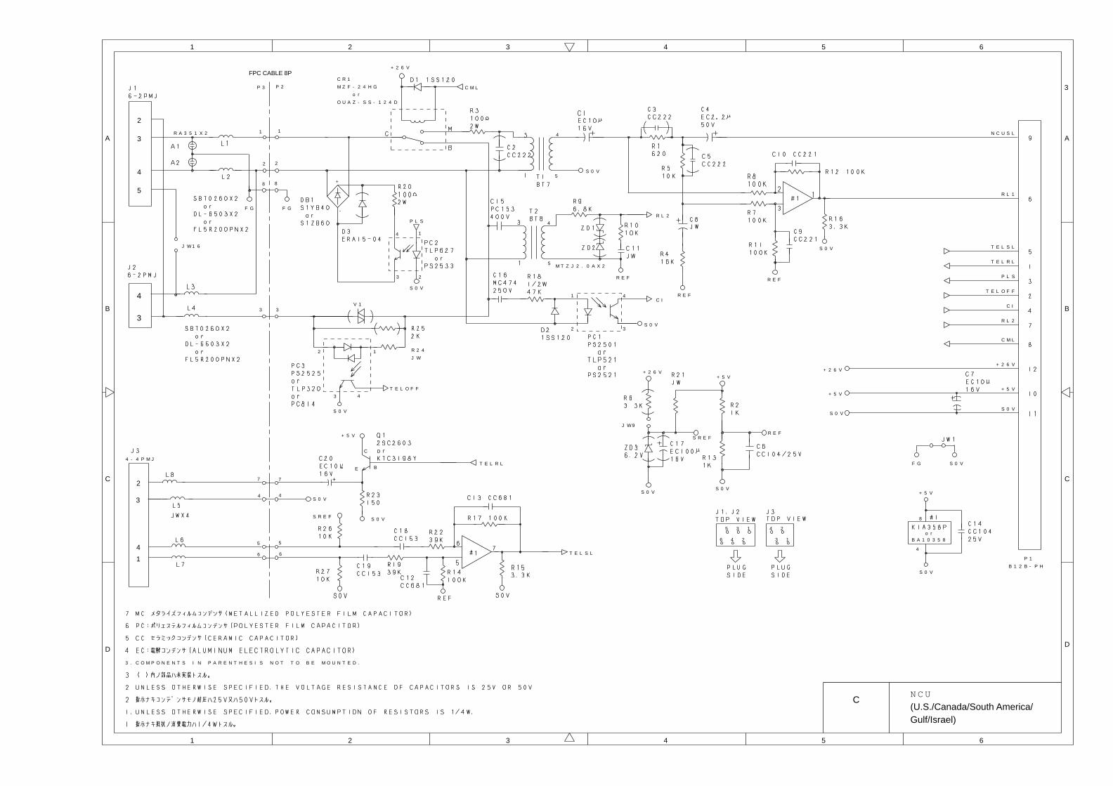
5
R E F
4
S 0 V
R A 3 5 1 X 2
+ 2 6 V
P 1
B 1 2 B - P HS 0 V
+ 5 V
8
4
S 0 V
6 3 1
4 21
R E F
4
3
4
3
S 0 V
+ 2 6 V
C M L
C R 1
M Z F - 2 4 H G
o r
O U A Z - S S - 1 2 4 D
F G
2
5
+ 5 V
S 0 V
S R E F
4 2
5 3
4
3
1
2
P L S
S 0 V
+
-
2
1 4
3S 0 V
R L 2
2 1
43
T E L O F F
M T Z J 2 . 0 A X 2
R E F
4
5
C I
S 0 V
S 0 V
N C U S L
S 0 V
+ 2 6 V
C M L
R L 2
C I
T E L O F F
P L S
T E L R L
R L 1
T E L S L
V 1
4 - 4 P M J
T E L S L4
3
2
S R E F
S 0 V
S 0 V
+ 5 V
C
E BT E L R L
1
+ 2 6 V
S 0 V
F GF G
+ 5 V+ 5 V
R E F
P 3 P 2
3 . C O M P O N E N T S I N P A R E N T H E S I S N O T T O B E M O U N T E D .
R 2 4
J W
1
2
8
3
7
4
5
6 6
5
4
7
3
8
2
1
J W 9
B A 1 0 3 5 8o r
J W 1 6
3
A
B
1 2 3
C
D
1 2 3 5 6
A
B
C
D
6
4
4 5
FPC CABLE 8P
CN C U
(U.S./Canada/South America/Gulf/Israel)

L I N E
S
E
M
BC
-
1 2
4
A - O U T
7
3
1
3
6
4
R D P S
D A S N D
-
+
R L 2
P L S
3
6
4
+ 2 6 V
+ 5 V
S 0 V
5
6T E L O F F 1
1
R E F
P O L
C H 2
F G
4
3
1
2
+
M
BC
M
BC
CB
M
S P 3
E
R E F
-
+
S 0 V
A - O U T
R 2 7
1 0 K
C M L
S 0 V
D A S T
T E L O F F 1
A D L C
C M L
S 0 V
R E F
+ 5 V
+ 5 V
S 0 V
E
T E L R L
R L 1
+ 5 V
S 0 V
S 0 V
-+
+ -
P 2
I M S A - 6 0 3 3 B
- 1 8 Z
o r
1 2
1 1
1 0
8
3
2
5
1
9
6
7
2 0
1 3
1 8
1 7
1 5
4
1 6
1 9
E A R T H1 4
S 0 V
12
3
-
+
R E F
41 41
R D P S
S 0 V
R D P S
+ 5 V
3322 32
41
S 0 V
1
2
4
3
P L S
J W ( 5 ) X 2
J P 2 5
( 1 0 )
J P 2 6
( 5 )
J P 2 3
( 5 )
J P 2 0
( 5 )
J P 1 1
( 1 0 )
J P 8
( 5 )
J P 2 9 ( C )
J P 1 9 ( 2 0 ) J P
3 0
( C )
J P 2 2 ( 1 0 )
J P 2 1
( 2 0 )
J P 2 8 ( C )
J P 1 7 ( 5 )
J P 9
( 1 0 )
J P 1 8
( 5 )
J P 2 7 ( C )
T A D
B I N A T O N E
2
S 0 V
C N 3
4 - 4 P M J
+
-
S 0 V
S O V
DG
SD A S N D
T E L R L
R E F
S 0 VS 0 V
+ 5 V
J W 9
( 1 0 )
J W 1 0
( 1 0 )
J W 1 1
( 1 0 )
J W 8
( 1 0 )
1
2P 1
B 2 B - P H
S 0 V
S 0 V
J P 3
( 1 0 )
+ 5 V ; J P 5 ( 5 ) J P 7 ( 5 ) J P 1 0 ( 1 0
J P 1 2 ( 5 ) J P 1 6 ( 1 0 )
S 0 V ; J P 1 5 ( 1 0 ) J P 2 4 ( 5 )
J P 3 2 ( C )
+ 2 6 V ; J P 1 4 ( 1 0 ) J P 3 1 ( C )
R E F ; J P 1 ( 5 ) J P 2 ( 5 ) J P 4 ( 1 0 )
+ 5 V
A
B
1 2 3
C
D
1 2 3 5 6
A
B
C
D
6
4
4 5
OR 56Ω 2W (SW1)
C N C U
(Germany/Australia/Switzerland)

T A D
B I N A T O N E
L I N E
S
E
M
BC
-
1 2
4
A - O U T
7
3
1
3
6
4
R D P S
D A S N D
-
+
R L 2
P L S
3
6
4
+ 2 6 V
+ 5 V
S 0 V
1
2
4
3
S 0 V
5
6T E L O F F 1
1
R E F
P O L
C H 2
F G
4
3
1
2
+
M
BC
M
BC
CB
M
E
S 0 V
R E F
-
+
S 0 V
A - O U T
R 2 7
1 0 K
C M L
S 0 V
D A S T
T E L O F F 1
A D L C
C M L
S 0 V
P H 1
T L P 6 2 6 B V
R E F
+ 5 V
+ 5 V
S 0 V
E
T E L R L
R L 1
+ 5 V
S 0 V
S 0 V
-+
+ -
P 2
I M S A - 6 0 3 3 B
- 1 8 Z
o r
1 2
1 1
1 0
8
3
2
5
1
9
6
7
2 0
1 3
1 8
1 7
1 5
4
1 6
1 9
E A R T H1 4
S 0 V
12
3
-
+
R E F
41 41
R D P S
S 0 V
R D P S
+ 5 V
3322 32
41
S 0 V
1
2
4
3
P L S
P 2 : B 1 2 B - P H , P 3 : B 6 B - P H
J P 2 5
( 1 0 )
J P 2 6
( 5 )
J P 2 3
( 5 )
J P 2 0
( 5 )
J P 8
( 5 )
J P 1 1
( 1 0 )
J P 1 9 ( 2 0 ) J P
3 0
( C )
J P 2 2 ( 1 0 )
J P 2 1
( 2 0 )
J P 2 8 ( C )
J P 1 7 ( 5 )
J P 9
( 1 0 )
J P 1 8
( 5 )
J P 2 7 ( C )
J P 6 ( 5 )
2
S 0 V
C N 3
4 - 4 P M J
+ 5 V
+
-
S 0 V
S O V
DG
SD A S N D
T E L R L
R E F
S 0 VS 0 V
+ 5 V
J W 9
( 1 0 )
J W 1 0
( 1 0 )
J W 1 1
( 1 0 )
J W 8
( 1 0 )
1
2P 1
B 2 B - P H
S 0 V
S 0 V
J P 3
( 1 0 )
+ 5 V ; J P 5 ( 5 ) J P 7 ( 5 ) J P 1 0 ( 1 0 )
J P 1 2 ( 5 ) J P 1 6 ( 1 0 )
S 0 V ; J P 1 5 ( 1 0 ) J P 2 4 ( 5 )
J P 3 2 ( C )
+ 2 6 V ; J P 1 4 ( 1 0 ) J P 3 1 ( C )
R E F ; J P 1 ( 5 ) J P 2 ( 5 ) J P 4 ( 1 0 )
A
B
1 2 3
C
D
1 2 3 5 6
A
B
C
D
6
4
4 5
CN C U
(U.K./Norway/Sweden/Ireland/New Zealand/South Africa)
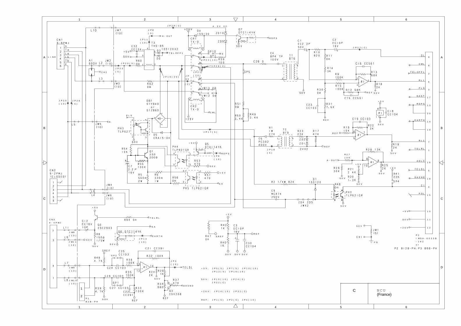
L I N E
S
E
M
BC
-
1 2
4
A - O U T
7
3
1
3
6
4
R D P S
D A S N D
-
+
R L 2
P L S
3
6
4
+ 2 6 V
+ 5 V
S 0 V
5
6T E L O F F 1
1
R E F
P O L
C H 2
F G
4
3
1
2
+
M
BC
M
BC
CB
M
E
R E F
-
+
S 0 V
A - O U T
R 2 7
1 0 K
C M L
S 0 V
D A S T
T E L O F F 1
A D L C
C M L
S 0 V
R E F
S P 7
+ 5 V
+ 5 V
S 0 V
E
T E L R L
R L 1
+ 5 V
S 0 V
S 0 V
-+
+ -
P 2
I M S A - 6 0 3 3 B
- 1 8 Z
o r
1 2
1 1
1 0
8
3
2
5
1
9
6
7
2 0
1 3
1 8
1 7
1 5
4
1 6
1 9
E A R T H1 4
S 0 V
12
3
-
+
R E F
41 41
R D P S
S 0 V
R D P S
+ 5 V
3322 32
41
+ 5 V
S 0 V
4 . 3 V X 2
E A
1
2
4
3
1
2
4
3
P L S
J P 2 5
( 1 0 )
J P 2 6
( 5 )
J P 2 3
( 5 )
J P 2 0 ( 5 )
J P 1 1
( 1 0 )
J P 8
( 5 )
J P 2 9 ( C )
J P 1 9 ( 2 0 ) J P
3 0
( C )
J P 2 2 ( 1 0 )
J P 2 1
( 2 0 )
J P 2 8 ( C )
J P 2 7 ( C )
J P 1 8
( 5 )
J P 1 7 ( 5 )
J P 9
( 1 0 )
2
S 0 V
C N 3
4 - 4 P M J
+ 5 V
S 0 V
+
-
S 0 V
S O V
DG
SD A S N D
T E L R L
R E F
S 0 V
S R E F
S 0 V
+ 5 V
J W 9
( 1 0 )
J W 1 0
( 1 0 )
J W 1 1
( 1 0 )
J W 8
( 1 0 )
S P 2
1
2P 1
B 2 B - P H
S 0 V
E A
S 0 V
E A R T HJ P 1 3
( 1 0 )
J P 3
( 1 0 )
+ 5 V ; J P 5 ( 5 ) J P 7 ( 5 ) J P 1 0 ( 1 0 )
J P 1 2 ( 5 ) J P 1 6 ( 1 0 )
S 0 V ; J P 1 5 ( 1 0 ) J P 2 4 ( 5 )
J P 3 2 ( C )
+ 2 6 V ; J P 1 4 ( 1 0 ) J P 3 1 ( C )
R E F ; J P 1 ( 5 ) J P 2 ( 5 ) J P 4 ( 1 0 )
A
B
1 2 3
C
D
1 2 3 5 6
A
B
C
D
6
4
4 5
C N C U(France)
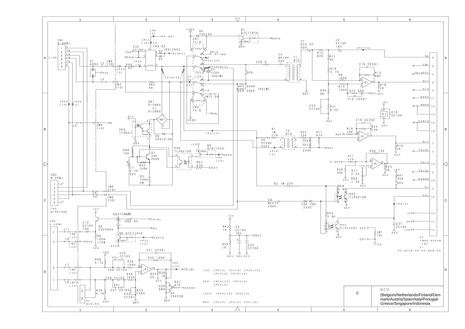
T A D
B I N A T O N E
L I N E
S
E
M
BC
-
1 2
4
A - O U T
7
3
1
3
6
4
R D P S
D A S N D
-
+
R L 2
P L S
3
6
4
+ 2 6 V
+ 5 V
S 0 V
1
2
4
3
S 0 V
5
6T E L O F F 1
1
R E F
P O L
C H 2
F G
4
3
1
2
+
M
BC
M
BC
CB
M
E
S 0 V
R E F
-
+
S 0 V
A - O U T
R 2 7
1 0 K
C M L
S 0 V
D A S T
T E L O F F 1
A D L C
C M L
S 0 V
P H 1
T L P 6 2 6 B V
R E F
+ 5 V
+ 5 V
S 0 V
E
T E L R L
R L 1
+ 5 V
S 0 V
S 0 V
-+
+ -
P 2
I M S A - 6 0 3 3 B
- 1 8 Z
o r
1 2
1 1
1 0
8
3
2
5
1
9
6
7
2 0
1 3
1 8
1 7
1 5
4
1 6
1 9
E A R T H1 4
S 0 V
12
3
-
+
R E F
41 41
R D P S
S 0 V
R D P S
+ 5 V
3322 32
41
S 0 V
1
2
4
3
P L S
P 2 : B 1 2 B - P H , P 3 : B 6 B - P H
J P 2 5
( 1 0 )
J P 2 6
( 5 )
J P 2 3
( 5 )
J P 2 0
( 5 )
J P 1 1
( 1 0 )
J P 8
( 5 )
J P 1 9 ( 2 0 ) J P
3 0
( C )
J P 2 2 ( 1 0 )
J P 2 1
( 2 0 )
J P 2 8 ( C )
J P 2 7 ( C )
J P 1 8
( 5 )
J P 6 ( 5 )
J P 1 7 ( 5 )
J P 9
( 1 0 )
2
S 0 V
C N 3
4 - 4 P M J
+ 5 V
S 0 V
+
-
S 0 V
S O V
DG
SD A S N D
T E L R L
R E F
S 0 VS 0 V
+ 5 V
J W 9
( 1 0 )
J W 1 0
( 1 0 )
J W 1 1
( 1 0 )
J W 8
( 1 0 )
S P 2
1
2P 1
B 2 B - P H
S 0 V
E A
S 0 V
E A R T HJ P 1 3
( 1 0 )
J P 3
( 1 0 )
+ 5 V ; J P 5 ( 5 ) J P 7 ( 5 ) J P 1 0 ( 1 0 )
J P 1 2 ( 5 ) J P 1 6 ( 1 0 )
S 0 V ; J P 1 5 ( 1 0 ) J P 2 4 ( 5 )
J P 3 2 ( C )
+ 2 6 V ; J P 1 4 ( 1 0 ) J P 3 1 ( C )
R E F ; J P 1 ( 5 ) J P 2 ( 5 ) J P 4 ( 1 0 )
A
B
1 2 3
C
D
1 2 3 5 6
A
B
C
D
6
4
4 5
CN C U
(Belgium/Netherlands/Finland/Den-mark/Austria/Spain/Italy/Portugal/Greece/Singapore/Indonesia
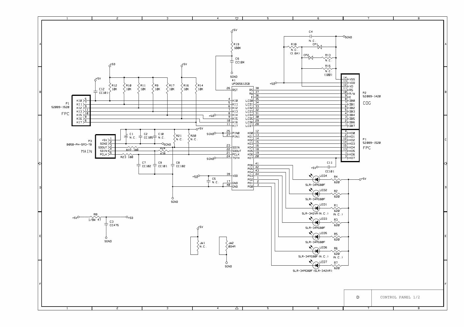
D CONTROL PANEL 1/2

K E Y N O P P F 3 5 5 0 K E Y C O D E
1
2
3
4
5
6
7
8
9
1 0
1 1
1 2
1 3
1 4
1 5
1 6
1 7
1 8
1 9
2 0
2 1
2 2
2 3
2 4
2 5
2 6
2 7
2 8
2 9
3 0
3 1
3 2
3 3
3 4
3 5
3 6
3 7
3 8
3 9
4 0
4 1
4 2
M F C 2 P A N E L K E Y M A T R I X R E F E R E N C E T A B L E
3 6
3 E
1 E
2 E
2 C
1 4
3 C
3 0
1 9
2 A
1 A
2 F
1 F
2 B
1 C
0 4
0 C
1 B
1 8
0 8
1 1
0 1
1 2
0 2
1 7
0 7
1 3
3 B
0 B
3 8
0 F
0 A
3 1
2 8
2 3
2 8 3 8 2 7 1 5 4 8
1 7 1 6
3 4 4 4 2 4 4 1 2 0
4 9
3 2 4 2 1 9 5 3 1 8
5 K I 0
7 K I 1
9 K I 2
1 1 K I 3
1 0 K I 5
8 K I 6
C N N
K O 0 K O 1 K O 2 K O 3 K O 4 K O 5
4 2 1 2 1 4 1 5 1 3C N N
P 1 1 4 P
B 5 3 K 2 5 9F P C N O
M F C
0 3
3 3
4 3
4 4
4 5
4 6
4 7
4 8 2 1
2 4
1 0
3 9
0 9
3 A
2 0
2 9
3 4
1 6
0 6
0 E
4 7 3 7
3 9
5 4 4 3
1
5 2
K O 6 K O 7
1 3
2 2 2 3 2 1 3 5 89 1 1 1 0
4 03 0 5 1 5 0
4 2 5 7 3
2 9
S e t
C l e a r
T e l - i n d e x
R e s o l u t i o n
M o d e
H o o k
1 0 K E Y - 1
1 0 K E Y - 2 / A B C
1 0 K E Y - 3 / D E F
1 T O U C H - 0 1 / 2 1
1 T O U C H - 0 2 / 2 2
1 T O U C H - 0 3 / 2 3
H o l d
1 0 K E Y - 4 / G H I
1 0 K E Y - 5 / J K L
1 0 K E Y - 6 / M N O
1 T O U C H - 0 6 / 2 6
1 T O U C H - 0 7 / 2 7
1 T O U C H - 0 8 / 2 8
S t o p
R e d i a l / P a u s e
1 0 K E Y - 7 / P Q R S
1 0 K E Y - 8 / T U V
1 0 K E Y - 9 / W X Y Z
1 T O U C H - 1 1 / 3 1
1 T O U C H - 1 2 / 3 2
1 T O U C H - 1 3 / 3 3
S t a r t
S p e e d D i a l
1 0 K E Y - *
1 0 K E Y - 0
1 0 K E Y - #
4 9
5 0
5 1
5 2
5 3
5 4
S h i f t
1 T O U C H - 1 6 / 3 6
1 T O U C H - 1 7 / 3 7
1 T O U C H - 1 8 / 3 8
S e t
F u n c t i o nF u n c t i o n
C l e a r
T e l - i n d e x
R e s o l u t i o n
M o d e
C o v e r p a g e
S u p e r Q . S c a n
H e l p
H o o k
1 0 K E Y - 1
1 0 K E Y - 2 / A B C
1 0 K E Y - 3 / D E F
1 T O U C H - 0 1 / 1 3
1 T O U C H - 0 3 / 1 5
1 T O U C H - 0 3 / 1 5
O n / O f f L i n e
P h o t o
* R e c o r d
* E r a s e
* P l a y
-H o l d
1 0 K E Y - 4 / G H I
1 0 K E Y - 5 / J K L
1 0 K E Y - 6 / M N O
1 T O U C H - 0 4 / 1 6
1 T O U C H - 0 5 / 1 7
1 T O U C H - 0 6 / 1 8
F F / C o n t
S o r t
S t o p
R e d i a l / P a u s e
1 0 K E Y - 7 / P Q R S
1 0 K E Y - 8 / T U V
1 0 K E Y - 9 / W X Y Z
1 T O U C H - 0 7 / 1 9
1 T O U C H - 0 8 / 2 0
1 T O U C H - 0 9 / 2 1
T e s t / R e s e t
E n l a r g e / R e d u c e
S t a r t
S p e e d D i a l
1 0 K E Y - *
1 0 K E Y - #
1 0 K E Y - 0
S h i f t
1 T O U C H - 1 0 / 2 2
1 T O U C H - 1 1 / 2 3
1 T O U C H - 1 2 / 2 4
P r i n t P r i o r i t y
C o p y
S u p e r Q . S c a n
H e l p
E n l a r g e / R e d u c e
C o p y
1 T O U C H - 0 4 / 2 4
1 T O U C H - 0 5 / 2 5
1 T O U C H - 0 9 / 2 9
1 T O U C H - 1 0 / 3 0
1 T O U C H - 1 4 / 3 4
1 T O U C H - 1 5 / 3 5
1 T O U C H - 1 9 / 3 9
1 T O U C H - 2 0 / 4 0
2 6
3 2
2 2
3 7
2 7
3 3
2 6 3 6 1 3 4 6 1 2
6 K I 7
4 5
3 1
2 5
6
1 4
M F C : M F C 4 5 5 0 / M F C 6 5 5 0 M C / M F C 7 5 5 0 M C
* : o n l y f o r M C m o d e l
---
A
B
1 2 3
C
D
1 2 3 5 6
A
B
C
D
6
4
4 5
PORT
PORT
D CONTROL PANEL 2/2

July '96
5X52011
Printed in Japan