Bronze Gate, Globe, Angle, and Check...
34
MSS SP-80-2008 Bronze Gate, Globe, Angle, and Check Valves Standard Practice Developed and Approved by the Manufacturers Standardization Society of the Valve and Fittings Industry, Inc. 127 Park Street, NE Vienna, Virginia 22180 Phone: (703) 281-6613 Fax: (703) 281-6671 E-mail [email protected] www.mss-hq.org Copyright MSS Provided by IHS under license with MSS Not for Resale No reproduction or networking permitted without license from IHS --`,,```,,,,````-`-`,,`,,`,`,,`--- //^:^^#^~^^""~:""~:$:@@:"#:$@"""^^#"@:~~"^~:^^::*#^#$\\
Transcript of Bronze Gate, Globe, Angle, and Check...

MSS SP-80-2008
Bronze Gate, Globe, Angle, and Check Valves
Standard Practice Developed and Approved by the Manufacturers Standardization Society of the Valve and Fittings Industry, Inc. 127 Park Street, NE Vienna, Virginia 22180 Phone: (703) 281-6613 Fax: (703) 281-6671 E-mail [email protected]
www.mss-hq.org
Copyright MSS Provided by IHS under license with MSS
Not for ResaleNo reproduction or networking permitted without license from IHS
--`,,```,,,,````-`-`,,`,,`,`,,`---
//^:^^#^~^^""~:""~:$:@@
:"#:$@"""^^#"@
:~~"^~:^^::*#^#$\\
MSS STANDARD PRACTICE SP-80
i
This MSS Standard Practice was developed under the consensus of the MSS Technical Committee 203 and the MSS Coordinating Committee. The content of this Standard Practice is the result of the efforts of competent and concerned volunteers to provide an effective, clear, and non-exclusive specification that will benefit the industry as a whole. This MSS Standard Practice is intended as a basis for common practice by the manufacturer, the user, and the general public. The existence of an MSS Standard Practice does not in itself preclude the manufacture, sale, or use of products not conforming to the Standard Practice. Mandatory conformance is established only by reference in a code, specification, sales contract, or public law, as applicable. Unless otherwise specifically noted in this MSS SP, any standard referred to herein is identified by the date of issue that was applicable to the referenced standard(s) at the date of issue of this MSS SP. (See Annex C.) U.S. customary units in this SP are the standard; the metric units are for reference only.
This document has been substantially revised from the previous 2003 edition. It is suggested that if the user is interested in knowing what changes have been made, that direct page-by-page comparison should be made of this document with the previous edition.
Any part of this Standard Practice may be quoted. Credit lines should read `Extracted from MSS SP-80, 2008 with permission of the publisher, the Manufacturers Standardization Society.' Reproduction prohibited under copyright convention unless written permission is granted by the Manufacturers Standardization Society of the Valve and Fittings Industry Inc. Originally Approved November, 1974
Copyright ©, 2003 by Manufacturers Standardization Society
of the Valve and Fittings Industry, Inc.
Printed in U.S.A.
Copyright MSS Provided by IHS under license with MSS
Not for ResaleNo reproduction or networking permitted without license from IHS
--`,,```,,,,````-`-`,,`,,`,`,,`---
//^:^^#^~^^""~:""~:$:@@:"#:$@"""^^#"@:~~"^~:^^::*#^#$\\
MSS STANDARD PRACTICE SP-80
ii
TABLE OF CONTENTS
SECTION PAGE
0 PURPOSE........................................................................................................................................... 1 1 SCOPE AND VALVE TYPES .......................................................................................................... 1 2 PRESSURE-TEMPERATURE RATINGS........................................................................................ 2 3 MATERIALS ..................................................................................................................................... 4 4 DESIGN.............................................................................................................................................. 4 5 MARKINGS..................................................................................................................................... 13 6 TOLENRANCE................................................................................................................................ 13 7 INSPECTION AND TESTING........................................................................................................ 13
TABLE 1 Pressure-Temperature Ratings .......................................................................................................... 3 2 List of Material Specifications .......................................................................................................... 5 3 Minimum Length and Depth of Thread ............................................................................................ 8 4 Bronze Gate Valves-Diameter of Stem........................................................................................... 11 5 Bronze Globe and Angle Valves-Diameter of Stem ....................................................................... 11 6 Bronze Gate Valves - Diameter of Handwheel............................................................................... 12 7 Bronze Globe and Angle Valves-Diameter of Handwheel ............................................................. 12 8 Shell Test-Threaded and Solder End Valves .................................................................................. 13 9 Shell Test-Flanged End Valves....................................................................................................... 13 10 Seat Test-Threaded and Solder End Valves.................................................................................... 14 11 Seat Test-Flanged End Valves ........................................................................................................ 14 A1 Pressure-Temperature Limitations .................................................................................................. 15 X1-1 Pressure-Temperature Limitations .................................................................................................. 25 X1-2 Pressure-Temperature Ratings ........................................................................................................ 26 X1-3 Minimum Length and Depth of Thread .......................................................................................... 27 X1-4 Bronze Gate Valves-Diameter of Stem........................................................................................... 28 X1-5 Bronze Globe and Angle Valves-Diameter of Stem ....................................................................... 28 X1-6 Bronze Gate Valves-Diameter of Handwheel................................................................................. 29 X1-7 Bronze Globe and Angle Valves-Diameter of Handwheel ............................................................. 29 X1-8 Shell Test-Threaded and Solder End Valves .................................................................................. 30 X1-9 Shell Test-Flanged End Valves....................................................................................................... 30 X1-10 Seat Test-Threaded and Solder End Valves.................................................................................... 30 X1-11 Seat Test-Flanged End Valves ........................................................................................................ 30 FIGURE B1 Gate Valve-Type 1A, Solid Wedge, Non-Rising Stem, External Stuffing Box ............................. 16 B2 Gate Valve-Type 1B, Solid Wedge, Non-Rising Stem, Internal Retaining Nut ............................. 16 B3 Gate Valve-Type 2, Solid Wedge, Inside Screw, Rising Stem ....................................................... 17 B4 Gate Valve-Type 3, Split Wedge (Double Disc), Inside Screw, Rising Stem ................................ 18 B5 Gate Valve-Type 4, Double Disc, Parallel Seat, Inside Screw, Rising Stem.................................. 18 B6 Globe and Angle Valves-Type 1, Metal Disc, Integral Seat ........................................................... 19 B7 Globe and Angle Valves-Type 2, Non-Metal Disc, Integral Seat................................................... 19 B8 Globe and Angle Valves-Type 3, Metal Disc, Removable Seat ..................................................... 20 B9 Check Valve-Type 1, Horizontal Lift Check - Metal to Metal Seat ............................................... 21 B10 Check Valve-Type 1, Angle Lift Check - Metal to Metal Seat....................................................... 21 B11 Check Valve-Type 2, Horizontal and Angle Lift Check - Non-Metallic to Metal Seat.................. 22 B12 Check Valve-Type 2, Vertical Lift Check - Non-Metallic to Metal Seat ....................................... 22 B13 Check Valve-Type 3, Swing Check, Metal to Metal Seat .............................................................. 23 B14 Check Valve-Type 4, Swing Check, Non-Metallic Disc to Metal Seat .......................................... 23 ANNEX A Strength of Solder Joints ................................................................................................................. 15 B Valve Types .................................................................................................................................... 16 C Referenced Standards and Applicable Dates .................................................................................. 24 X1 Metric References ........................................................................................................................... 25
Copyright MSS Provided by IHS under license with MSS
Not for ResaleNo reproduction or networking permitted without license from IHS
--`,,```,,,,````-`-`,,`,,`,`,,`---
//^:^^#^~^^""~:""~:$:@@:"#:$@"""^^#"@:~~"^~:^^::*#^#$\\
MSS STANDARD PRACTICE SP-80
1
0. PURPOSE
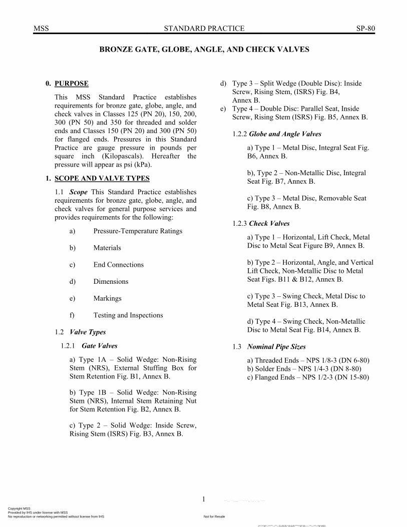
This MSS Standard Practice establishes requirements for bronze gate, globe, angle, and check valves in Classes 125 (PN 20), 150, 200, 300 (PN 50) and 350 for threaded and solder ends and Classes 150 (PN 20) and 300 (PN 50) for flanged ends. Pressures in this Standard Practice are gauge pressure in pounds per square inch (Kilopascals). Hereafter the pressure will appear as psi (kPa).
1. SCOPE AND VALVE TYPES
1.1 Scope This Standard Practice establishes requirements for bronze gate, globe, angle, and check valves for general purpose services and provides requirements for the following:
a) Pressure-Temperature Ratings b) Materials c) End Connections d) Dimensions e) Markings f) Testing and Inspections
1.2 Valve Types
1.2.1 Gate Valves
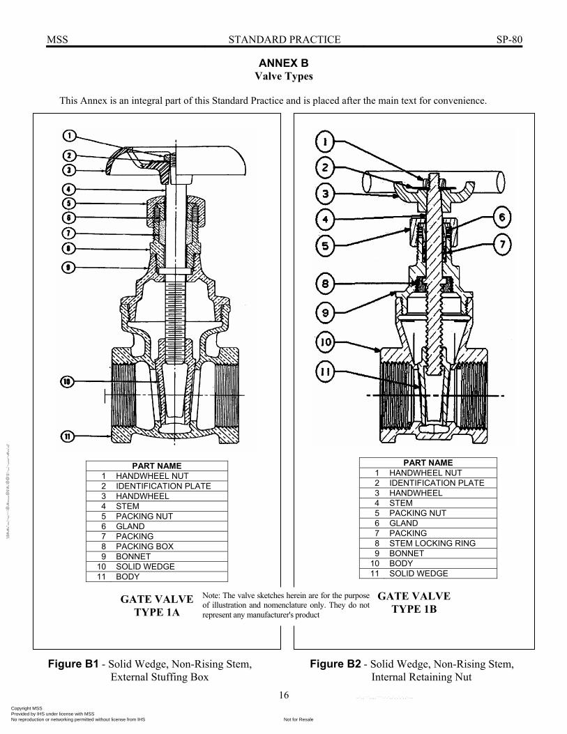
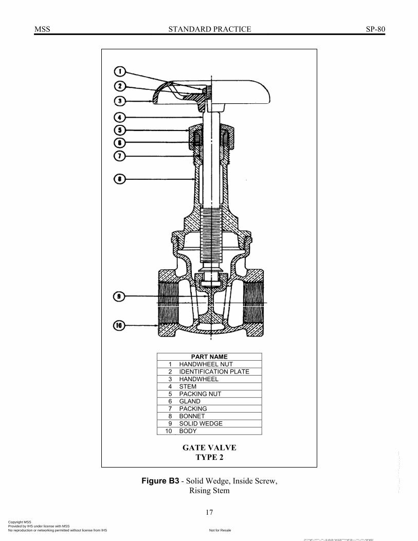
a) Type 1A – Solid Wedge: Non-Rising Stem (NRS), External Stuffing Box for Stem Retention Fig. B1, Annex B. b) Type 1B – Solid Wedge: Non-Rising Stem (NRS), Internal Stem Retaining Nut for Stem Retention Fig. B2, Annex B. c) Type 2 – Solid Wedge: Inside Screw, Rising Stem (ISRS) Fig. B3, Annex B.
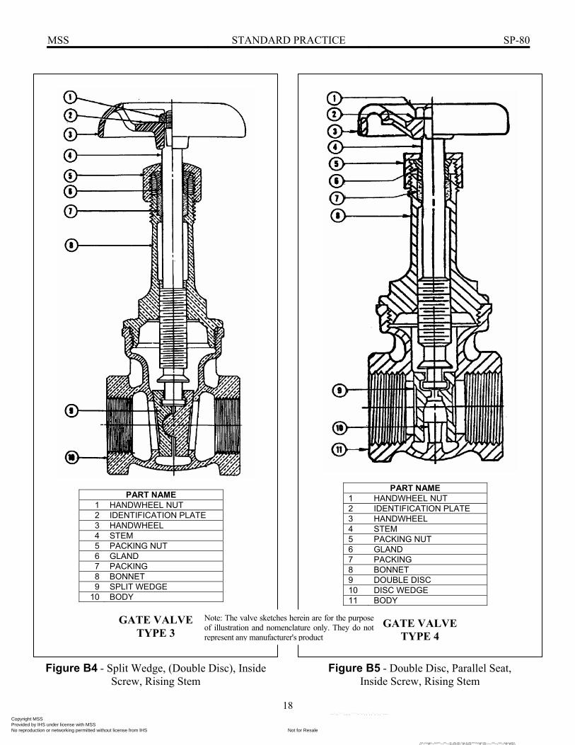
d) Type 3 – Split Wedge (Double Disc): Inside Screw, Rising Stem, (ISRS) Fig. B4, Annex B. e) Type 4 – Double Disc: Parallel Seat, Inside Screw, Rising Stem (ISRS) Fig. B5, Annex B.
1.2.2 Globe and Angle Valves
a) Type 1 – Metal Disc, Integral Seat Fig. B6, Annex B. b), Type 2 – Non-Metallic Disc, Integral Seat Fig. B7, Annex B. c) Type 3 – Metal Disc, Removable Seat Fig. B8, Annex B.
1.2.3 Check Valves
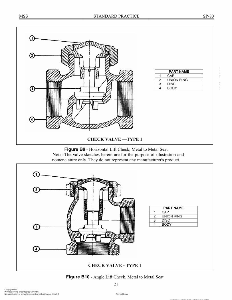
a) Type 1 – Horizontal, Lift Check, Metal Disc to Metal Seat Figure B9, Annex B. b) Type 2 – Horizontal, Angle, and Vertical Lift Check, Non-Metallic Disc to Metal Seat Figs. B11 & B12, Annex B. c) Type 3 – Swing Check, Metal Disc to Metal Seat Fig. B13, Annex B. d) Type 4 – Swing Check, Non-Metallic Disc to Metal Seat Fig. B14, Annex B.
1.3 Nominal Pipe Sizes
a) Threaded Ends – NPS 1/8-3 (DN 6-80) b) Solder Ends – NPS 1/4-3 (DN 8-80) c) Flanged Ends – NPS 1/2-3 (DN 15-80)
BRONZE GATE, GLOBE, ANGLE, AND CHECK VALVES
Copyright MSS Provided by IHS under license with MSS
Not for ResaleNo reproduction or networking permitted without license from IHS
--`,,```,,,,````-`-`,,`,,`,`,,`---
//^:^^#^~^^""~:""~:$:@@:"#:$@"""^^#"@:~~"^~:^^::*#^#$\\

MSS STANDARD PRACTICE SP-80
2
2. PRESSURE-TEMPERATURE RATINGS
2.1 The pressure-temperature ratings in Table 1 (Table X1-2) apply to all products governed by this Standard Practice. Valves conforming to the requirements of this Standard Practice shall, in all respects, merit these ratings.
2.2 These ratings are the maximum allowable, non-shock pressures at the temperatures shown, and allowable pressures may be interpolated between temperatures shown.
2.3 The temperature shown, corresponding to the pressure rating, shall be the material temperature of the pressure retaining structure (the temperature rating). In view of the various environments in which piping components may be installed (i.e., insulated or not, and either heated or cooled), it is assumed that the material temperature of the pressure retaining structure is the temperature of the contained fluid. Use of a pressure rating at a material temperature other than the temperature of the contained fluid is the responsibility of the user, and subject to the requirements of applicable codes.
2.4 The safe pressure-temperature rating of a solder-joint piping system is dependent, not only on valve, fitting, and tubing strength, but also on the composition of the solder used for joints. Pressure-temperature limitations
for solder joints made with typical commercial solders are given in Annex A (Table X1-1 in Appendix X1). It shall be the responsibility of the user to select a solder composition that is compatible with the service conditions, as well as to assure the adequacy of workmanship employed in making the joints.
2.5 The ratings given in Table 1 at -20°F (-29°C) to 150°F (66°C) shall also apply at lower temperatures. Products that are to operate at low temperatures shall conform to the rules of the applicable codes under which they are to be used.
2.6 The safe pressure-temperature rating of valves fitted with non-metallic discs, (i.e., globe and angle valves, Type 2, and check valves, Types 2 and 4) is dependent upon the composition of the disc material. It shall be the responsibility of the user to specify the service application. When no service application is specified, discs suitable for steam service at rated working conditions shall be furnished in all bronze globe and angle valves, Type 2, and in all bronze check valves, Types 2 and 4. Users are advised to consult with the manufacturer in cases of doubt.
Copyright MSS Provided by IHS under license with MSS
Not for ResaleNo reproduction or networking permitted without license from IHS
--`,,```,,,,````-`-`,,`,,`,`,,`---
//^:^^#^~^^""~:""~:$:@@
:"#:$@"""^^#"@
:~~"^~:^^::*#^#$\\

MSS STANDARD PRACTICE SP-80
3
TABLE 1 Pressure -Temperature Ratings(f)
PRESSURE(c) - psi CLASS 125 150 200 300 350 END. THD THD FLG(b) THD THD(c) THD FLG(b) THD
SOLDER (c)
SOLDER (c)
SOLDER (c)
SOLDER (c)
MATERIAL TEMP.(a)
deg. F ASTM B 62 ASTM B 61 -20 To
150 200 300 225 400 1000 600 500 1000
200 185 270 210 375 920 560 475 920
250 170 240 195 350 830 525 450 830
300 155 210 180 325 740 490 425 750
350 140 180 165 300 650 450 400 670
400 — — — — — — 275 560 410 375 590
406 125 150 150 — — — — — — — — — —
450 120(d) 145(d) — — 250 480 375 350 510
500 — — — — — — 225 390 340 325 430
550 — — — — — — 200 300 300 300 350
NOTES: (a) - For lower temperatures, see Section 2.5 (b) - P-T Ratings - ASME B16.24 (c) - Refer to Section 2.4 for safe P-T rating for solder-joint piping systems. (d) - Some codes (i.e., - ASME BPVC, Section 1) limit the rating temperatures of the indicated material to 406°F. (e) - Alternate ratings for valve sizes 1/8 - 2 having threaded ends and union ring body-bonnet joints. (f) - See Table X 1-2 in Appendix X 1 for metric (SI) units.
Copyright MSS Provided by IHS under license with MSS
Not for ResaleNo reproduction or networking permitted without license from IHS
--`,,```,,,,````-`-`,,`,,`,`,,`---
//^:^^#^~^^""~:""~:$:@@
:"#:$@"""^^#"@
:~~"^~:^^::*#^#$\\
MSS STANDARD PRACTICE SP-80
4
3. MATERIALS
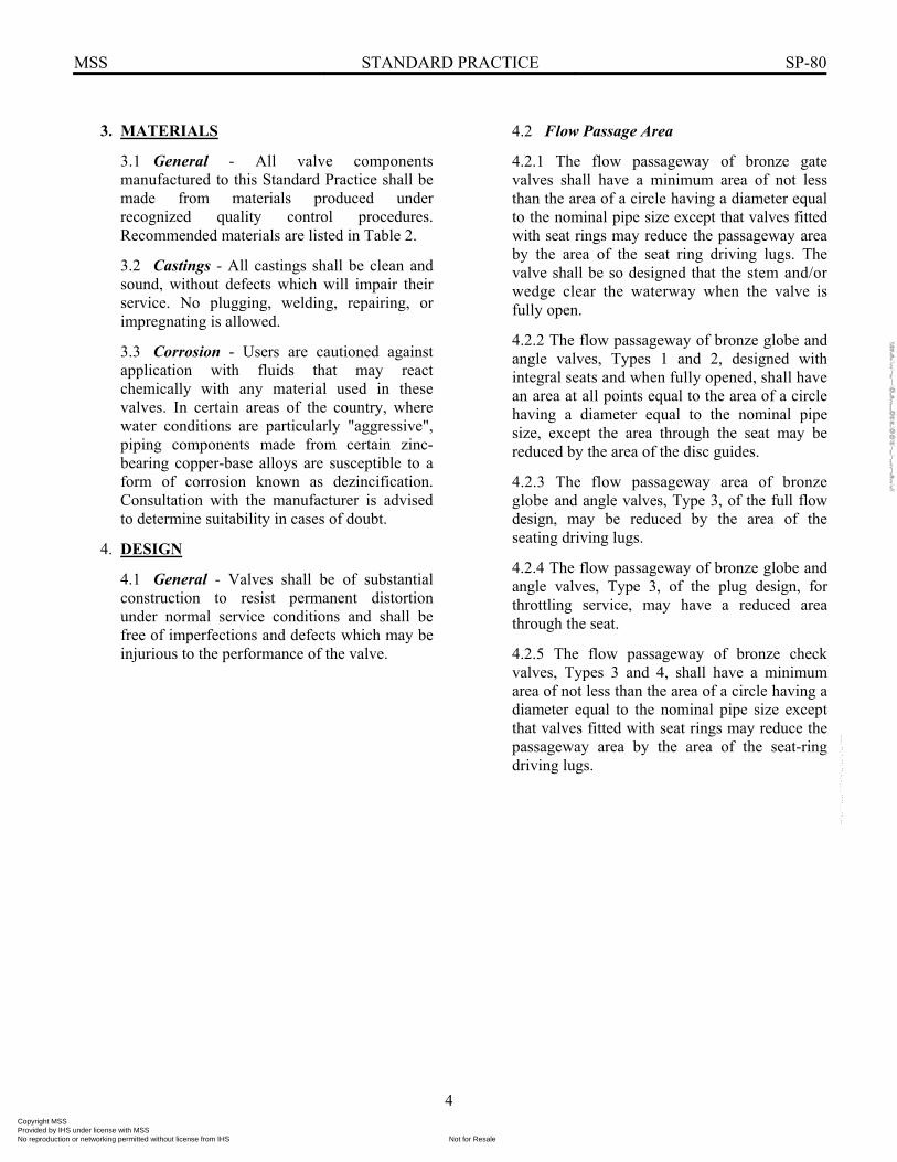
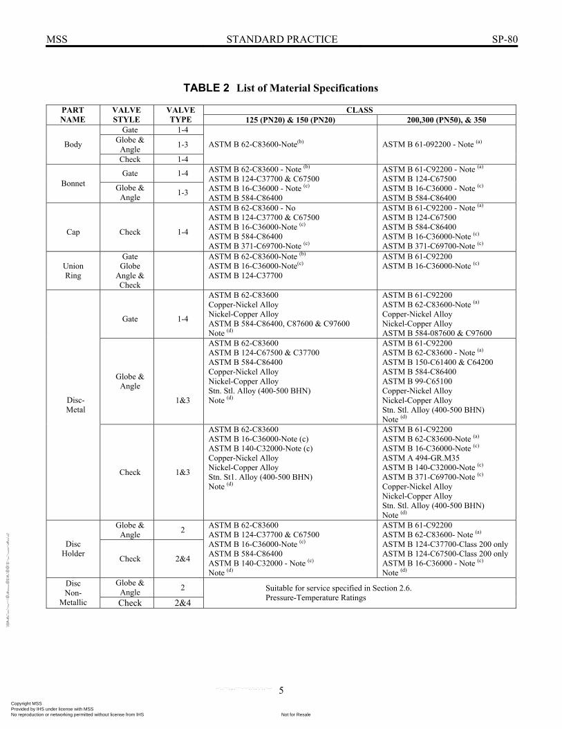
3.1 General - All valve components manufactured to this Standard Practice shall be made from materials produced under recognized quality control procedures. Recommended materials are listed in Table 2.
3.2 Castings - All castings shall be clean and sound, without defects which will impair their service. No plugging, welding, repairing, or impregnating is allowed.
3.3 Corrosion - Users are cautioned against application with fluids that may react chemically with any material used in these valves. In certain areas of the country, where water conditions are particularly "aggressive", piping components made from certain zinc-bearing copper-base alloys are susceptible to a form of corrosion known as dezincification. Consultation with the manufacturer is advised to determine suitability in cases of doubt.
4. DESIGN
4.1 General - Valves shall be of substantial construction to resist permanent distortion under normal service conditions and shall be free of imperfections and defects which may be injurious to the performance of the valve.
4.2 Flow Passage Area
4.2.1 The flow passageway of bronze gate valves shall have a minimum area of not less than the area of a circle having a diameter equal to the nominal pipe size except that valves fitted with seat rings may reduce the passageway area by the area of the seat ring driving lugs. The valve shall be so designed that the stem and/or wedge clear the waterway when the valve is fully open.
4.2.2 The flow passageway of bronze globe and angle valves, Types 1 and 2, designed with integral seats and when fully opened, shall have an area at all points equal to the area of a circle having a diameter equal to the nominal pipe size, except the area through the seat may be reduced by the area of the disc guides.
4.2.3 The flow passageway area of bronze globe and angle valves, Type 3, of the full flow design, may be reduced by the area of the seating driving lugs.
4.2.4 The flow passageway of bronze globe and angle valves, Type 3, of the plug design, for throttling service, may have a reduced area through the seat.
4.2.5 The flow passageway of bronze check valves, Types 3 and 4, shall have a minimum area of not less than the area of a circle having a diameter equal to the nominal pipe size except that valves fitted with seat rings may reduce the passageway area by the area of the seat-ring driving lugs.
Copyright MSS Provided by IHS under license with MSS
Not for ResaleNo reproduction or networking permitted without license from IHS
--`,,```,,,,````-`-`,,`,,`,`,,`---
//^:^
^#^~
^^""
~:""
~:$:
@@
:"#:$
@""
"^^#
"@:~
~"^~
:^^:
:*#^
#$\\
MSS STANDARD PRACTICE SP-80
5
TABLE 2 List of Material Specifications
CLASS PART NAME
VALVE STYLE
VALVE TYPE 125 (PN20) & 150 (PN20) 200,300 (PN50), & 350
Gate 1-4 Globe &
Angle 1-3 Body
Check 1-4
ASTM B 62-C83600-Note(b) ASTM B 61-092200 - Note (a)
Gate 1-4 Bonnet Globe &
Angle 1-3
ASTM B 62-C83600 - Note (b) ASTM B 124-C37700 & C67500 ASTM B 16-C36000 - Note (c) ASTM B 584-C86400
ASTM B 61-C92200 - Note (a) ASTM B 124-C67500 ASTM B 16-C36000 - Note (c) ASTM B 584-C86400
Cap
Check
1-4
ASTM B 62-C83600 - No ASTM B 124-C37700 & C67500 ASTM B 16-C36000-Note (c) ASTM B 584-C86400 ASTM B 371-C69700-Note (c)
ASTM B 61-C92200 - Note (a) ASTM B 124-C67500 ASTM B 584-C86400 ASTM B 16-C36000-Note (c) ASTM B 371-C69700-Note (c)
Union Ring
Gate Globe
Angle & Check
ASTM B 62-C83600-Note (b) ASTM B 16-C36000-Note(c) ASTM B 124-C37700
ASTM B 61-C92200 ASTM B 16-C36000-Note (c)
Gate
1-4
ASTM B 62-C83600 Copper-Nickel Alloy Nickel-Copper Alloy ASTM B 584-C86400, C87600 & C97600 Note (d)
ASTM B 61-C92200 ASTM B 62-C83600-Note (a) Copper-Nickel Alloy Nickel-Copper Alloy ASTM B 584-087600 & C97600
Globe & Angle
1&3
ASTM B 62-C83600 ASTM B 124-C67500 & C37700 ASTM B 584-C86400 Copper-Nickel Alloy Nickel-Copper Alloy Stn. Stl. Alloy (400-500 BHN) Note (d)
ASTM B 61-C92200 ASTM B 62-C83600 - Note (a) ASTM B 150-C61400 & C64200 ASTM B 584-C86400 ASTM B 99-C65100 Copper-Nickel Alloy Nickel-Copper Alloy Stn. Stl. Alloy (400-500 BHN) Note (d)
Disc- Metal
Check 1&3
ASTM B 62-C83600 ASTM B 16-C36000-Note (c) ASTM B 140-C32000-Note (c) Copper-Nickel Alloy Nickel-Copper Alloy Stn. St1. Alloy (400-500 BHN) Note (d)
ASTM B 61-C92200 ASTM B 62-C83600-Note (a) ASTM B 16-C36000-Note (c) ASTM A 494-GR.M35 ASTM B 140-C32000-Note (c) ASTM B 371-C69700-Note (c) Copper-Nickel Alloy Nickel-Copper Alloy Stn. Stl. Alloy (400-500 BHN) Note (d)
Globe & Angle 2
Disc Holder Check 2&4
ASTM B 62-C83600 ASTM B 124-C37700 & C67500 ASTM B 16-C36000-Note (c) ASTM B 584-C86400 ASTM B 140-C32000 - Note (c) Note (d)
ASTM B 61-C92200 ASTM B 62-C83600- Note (a) ASTM B 124-C37700-Class 200 only ASTM B 124-C67500-Class 200 only ASTM B 16-C36000 - Note (c) Note (d)
Globe & Angle 2 Disc
Non- Metallic Check 2&4
Suitable for service specified in Section 2.6. Pressure-Temperature Ratings
Copyright MSS Provided by IHS under license with MSS
Not for ResaleNo reproduction or networking permitted without license from IHS
--`,,```,,,,````-`-`,,`,,`,`,,`---
//^:^^#^~^^""~:""~:$:@@
:"#:$@"""^^#"@
:~~"^~:^^::*#^#$\\

MSS STANDARD PRACTICE SP-80
6
TABLE 2 List of Material Specifications (Continued)
CLASS PART NAME
VALVE STYLE
VALVE TYPE 125 (PN20) & 150 (PN20) 200,300 (PN50), & 350
Gate 1-4
Copper-Nickel Alloy Nickel-Copper Alloy Stn. Stl. Alloy (250-500 BHN) 300 Series Stn. Stl. Alloy-Note(b) Note(d)
Copper-Nickel Alloy Nickel-Copper Alloy Stn. Stl. Alloy (250-500 BHN) 300 Series Stn. Stl. Alloy-Note(b) Note(d)
Globe & Angle 3
Seat Rings
Check 1-4
Copper-Nickel Alloy Nickel-Copper Alloy Stn. Stl. Alloy (400-500 BHN) 300 Series Stn. Stl. Alloy-Note(b) Note(d)
Copper-Nickel Alloy Nickel-Copper Alloy Stn. Stl. Alloy (400-500 BHN) 300 Series Stn. Stl. Alloy-Note(b) Note(d)
Globe & Angle 2 Disc Nut
Disc Locknut
Check 2&4
ASTM B 62-C83600 ASTM B 16-C36000 ASTM B 150-C61400 & C64200 ASTM B 371-C69700 Note (d)
ASTM B 61-C92200 ASTM B 62-C83600 ASTM B 16-C36000 ASTM B 150-C61400 & C64200 ASTM B 371-C69700- Note (d)
Gate 1-4
Stem
Globe & Angle 1&3
ASTM B 61-C92200 ASTM B 62-C83600 ASTM B 98-C65100 ASTM B 99-C65100 ASTM B 148-C95600 ASTM B 150-C61400 & C64200 ASTM B 371-C69400 & C69700 ASTM B 584-C86400 & C87400 ASTM B 584-C87500 & C87600 ASTM B 21-C46400 & C47940 ASTM B 21-C48200 ASTM B 505-C83600 Note (d)
ASTM B 61-C92200 ASTM B 62-C83600-Note (a) ASTM B 98-C65100 ASTM B 99-C65100 ASTM B 148-C95600 ASTM B 371-C69400 & C69700 ASTM B 584-C86500 & C87400 ASTM B 584-C87500 & 87600 ASTM B 21-C46400 & C48200 ASTM B 505-C83600-Note(a) Note (d)
Hanger (Hinge) Check 3&4
ASTM B 62-C83600 ASTM B 584-C87600 Stainless Steel Alloy Note (d)
ASTM B 61-C92200 ASTM B 62-C83600 - Note (a) ASTM B 584-C87600 Note (d)
Hanger Pin (Hinge Pin) Side Plug Stop Plug Washer
Check 3&4
ASTM B 150-C61400 & C64200 ASTM B 16-C36000 ASTM B 371-C69700 Copper Alloy Nickel-Copper Alloy Stainless Steel Alloy
ASTM B 150-C61400 & C64200 ASTM B 16-C36000 ASTM B 371-C69700 Copper- Alloy Nickel-Copper Alloy Stainless Steel Alloy
Stuffing Box Packing Box
Stem-Locking-
Ring
Check Globe &
Angle
ASTM B 62-C83600 ASTM B 124-C37700 ASTM B 16-C36000 ASTM B 584-C86400 & C84400 ASTM B 283- Note(f) Other Copper Alloy materials having physical and corrosive properties equivalent to those of the listed materials
ASTM B 62-C83600 ASTM B 124-C37700 ASTM B 16-C36000-Note(g) ASTM B 584-C86400 ASTM B 584-C84400 - Note (e) ASTM B 283-Note (f) Other Copper Alloy materials having physical and corrosive properties equivalent to those of the listed materials
Copyright MSS Provided by IHS under license with MSS
Not for ResaleNo reproduction or networking permitted without license from IHS
--`,,```,,,,````-`-`,,`,,`,`,,`---
//^:^
^#^~
^^""
~:""
~:$:
@@
:"#:$
@""
"^^#
"@:~
~"^~
:^^:
:*#^
#$\\

MSS STANDARD PRACTICE SP-80
7
TABLE 2 List of Material Specifications (Continued)
CLASS PART NAME
VALVE STYLE
VALVE TYPE 125 (PN20) & 150 (PN20) 200,300 (PN50), & 350
Packing Gland
Packing Nut
Gate Globe &
Angle
ASTM B 62-C83600 ASTM B 124-C37700 ASTM B 16-C36000 ASTM B 584-C86400 & C84400 ASTM B 283- Note(f) Other Copper Alloy materials having physical and corrosive properties equivalent to those of the listed materials
ASTM B 62-C83600 ASTM B 124-C37700 ASTM B 16-C36000 ASTM B 584-C86400 ASTM B 584-C84400 - Note (e) ASTM B 283-Note (f) Other Copper Alloy materials having physical and corrosive properties equivalent to those of the listed materials
Retaining Ring Check 3&4 Copper Alloy
Stainless Steel Copper Alloy Stainless Steel
Handwheels Gate
Globe & Angle
Ferrous, non-ferrous alloys or of a non-metallic material of sufficient strength and durability.
NOTES:
(a) —
ASTM B 62-083600, may be used in place of ASTM B 61-C92200 for class 200, 300 (PN 50) and 350 valves provided that a temperature limitation of 450°F (232°C) is shown on the identification plate.
(b) — ASTM B 61-C92200 may be used in Class 125 (PN20) and 150 (PN20) valves at the manufacturer's option.
(c) — Bonnet, cap, disc, and disc holder, sizes 3/4 (DN 20) and smaller only. Union rings, sizes 3/8 (DN 10) and smaller only.
(d) — Other materials having physical- and corrosion-resistant properties equivalent to those of the listed material.
(e) — For use in Class 200 valves with non-metallic discs when temperature limitation of the disc is a maximum of 450°F (232°C).
(f) — Glands (non-bolted, non-threaded) only.
(g) — For sizes 3/4 (DN 20) and smaller.
(h) — Manufacturer's standard hardness.
Copyright MSS Provided by IHS under license with MSS
Not for ResaleNo reproduction or networking permitted without license from IHS
--`,,```,,,,````-`-`,,`,,`,`,,`---
//^:^
^#^~
^^""
~:""
~:$:
@@
:"#:$
@""
"^^#
"@:~
~"^~
:^^:
:*#^
#$\\
MSS STANDARD PRACTICE SP-80
8
4.3 Body and Bonnet
4.3.1 The body-bonnet joint on bronze gate, globe and angle valves and the body-cap joint on bronze check valves may be inside screw, screw-over, union ring or bolted construction.
4.3.2 Threaded Ends
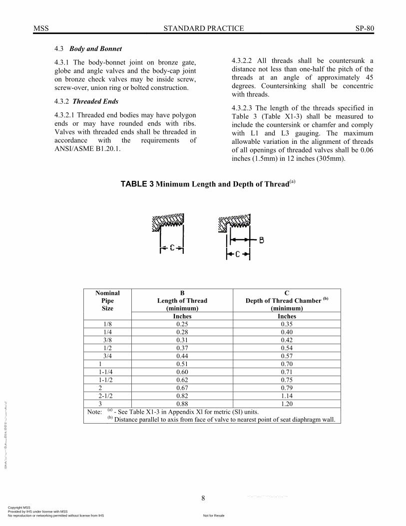
4.3.2.1 Threaded end bodies may have polygon ends or may have rounded ends with ribs. Valves with threaded ends shall be threaded in accordance with the requirements of ANSI/ASME B1.20.1.
4.3.2.2 All threads shall be countersunk a distance not less than one-half the pitch of the threads at an angle of approximately 45 degrees. Countersinking shall be concentric with threads.
4.3.2.3 The length of the threads specified in Table 3 (Table X1-3) shall be measured to include the countersink or chamfer and comply with L1 and L3 gauging. The maximum allowable variation in the alignment of threads of all openings of threaded valves shall be 0.06 inches (1.5mm) in 12 inches (305mm).
TABLE 3 Minimum Length and Depth of Thread(a)
B
Length of Thread (minimum)
C Depth of Thread Chamber (b)
(minimum)
Nominal Pipe Size
Inches Inches 1/8 0.25 0.35 1/4 0.28 0.40 3/8 0.31 0.42 1/2 0.37 0.54 3/4 0.44 0.57
1 0.51 0.70 1-1/4 0.60 0.71 1-1/2 0.62 0.75 2 0.67 0.79 2-1/2 0.82 1.14 3 0.88 1.20
Note: (a) - See Table X1-3 in Appendix Xl for metric (SI) units. (b) Distance parallel to axis from face of valve to nearest point of seat diaphragm wall.
Copyright MSS Provided by IHS under license with MSS
Not for ResaleNo reproduction or networking permitted without license from IHS
--`,,```,,,,````-`-`,,`,,`,`,,`---
//^:^^#^~^^""~:""~:$:@@
:"#:$@"""^^#"@
:~~"^~:^^::*#^#$\\

MSS STANDARD PRACTICE SP-80
9
4.3.3 Solder-Joint Ends Solder joint ends shall be prepared in accordance with applicable requirements of ASME B16.18.
4.3.4 Flanged Ends Flanges and drilling of flanged end valves shall be in accordance with applicable requirements of ASME B16.24. The finish of facing shall be in accordance with MSS SP-6.
4.3.5 Stem Thread Engagement
4.3.5.1 Rising-stem valves shall have a minimum length of stem-thread engagement equal to the outside diameter of the thread when the valve is closed and 75% of the outside diameter of the stem thread when the valve is fully open.
4.3.5.2 In the case of non-rising stem valves, the length of the stem thread in contact with the wedge shall be at least equal to the outside diameter of the thread when the valve is closed.
4.3.6 Backseat A backseat shall be provided in all types of gate, globe, and angle valves; however, repacking while the valve is pressurized is not recommended.
4.4 Discs and Seat Rings
4.4.1 Discs and Seat Rings for Bronze Gate Valves
4.4.1.1 Solid-wedge discs shall be of one-piece construction with disc guides. The stem chamber of the NRS discs shall be open at the bottom for proper drainage.
4.4.1.2 Split wedge and parallel seat discs (double disc) shall be designed so, that on reaching the point of closure, thrust from the stem will cause the disc to seat.
4.4.1.3 All discs shall have machined seating-surfaces and shall be securely attached to the stem in all operating positions.
4.4.1.4 Seats may have expanded-in, threaded-in, or otherwise renewable seat-rings or may be cast integral with the body at the manufacturer's option.
4.4.2 Discs and Seat Rings for Bronze Globe and Angle Valves
4.4.2.1 Discs or disc holders shall be fastened securely to the end of the stem in such a manner as to allow these parts to swivel freely. Valve Types 1 and 2 in sizes 1/2 (DN 15) and smaller, may have the disc or disc holder formed on the end of the stem. Discs, plugs, or disc holders of the slip-on type shall be adequately guided for self-centering and shall be so constructed, in relation to body and bonnet, that when the valve is fully opened, they will not slip off the stem.
Disc holders for Type 2 Valves shall be designed to contain the periphery of the non-metallic disc in position.
4.4.2.2 The seat may have an expanded-in, threaded-in, or otherwise renewable seat ring, or may be cast integral with the body at the manufacturer's option.
Copyright MSS Provided by IHS under license with MSS
Not for ResaleNo reproduction or networking permitted without license from IHS
--`,,```,,,,````-`-`,,`,,`,`,,`---
//^:^
^#^~
^^""
~:""
~:$:
@@
:"#:$
@""
"^^#
"@:~
~"^~
:^^:
:*#^
#$\\

MSS STANDARD PRACTICE SP-80
10
4.4.3 Discs and Seats for Bronze Check Valves
4.4.3.1 Bronze check valves, Types 1 and 2, shall have the disc or disc holder substantially guided to ensure proper seating.
4.4.3.2 Bronze check valves, Types 3 and 4, shall have disc and disc holder fastened securely to the hanger or hinge. The connection shall allow sufficient freedom so that the disc will properly seat by gravity. The joint shall swivel freely to allow uniform wear, except that disc or disc holders and hanger may be integral in Class 125 valves.
4.4.3.3 Disc holders for bronze check valves, Types 2 and 4, shall be designed to hold and support the non-metallic disc.
4.4.3.4 The seat may have an expanded-in, threaded-in, or otherwise renewable seat ring, or may be cast integral with the body at the manufacturer's option.
4.5 Stems for Bronze Gate Valves, and Bronze Globe and Angle Valves
Stems shall be threaded with either Acme form threads or 60° truncated "V" threads, so that the valve will be opened when the handwheel is rotated counter-clockwise. The handwheel end of the stem shall be a tapered square with its greatest diagonal equal approximately to the diameter of the stem or it may be of the splined or serrated design of equal strength. A threaded extension shall be provided to accommodate a handwheel nut.
The handwheel nut may be brass or, if made of steel, it shall have a corrosion protective plating. The diameter of that portion of the stem passing through the packing shall not be less than shown in Tables 4 (Table X1-4) and 5 (Table X1-5).
4.6 Packing Box and Packing Nut for Bronze Gate Valves and Bronze Globe and Angle Valves
4.6.1 Packing box for Class 125 (PN20) valves may be of gland-follower type or packing-nut type. Packing boxes for all other valves, sizes greater than 1/2 inch (DN15), shall be of the gland-follower type. The length of packing in contact with the stem shall be at least one diameter of the stem passing through it. The thread of the packing nut shall be of sufficient length to enable the nut to be threaded on to the packing box or bonnet at least two full threads, when the full amount of packing is in place, and the length of thread engagement between the packing box or bonnet and the packing nut shall be sufficient for full travel of the gland.
4.6.2 Stem Packing - Stem packing shall be braided, twisted, or formed ring type made from non-asbestos material, suitable for the pressure-temperature ratings of the valve.
4.7 Handwheels for Bronze Gate, Globe, and Angle Valves
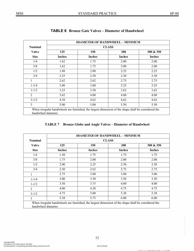
Handwheels smaller than 6 inches (152mm) in diameter shall be of the non-heat design with a raised rim to protect the hands. Handwheels 6 inch (152mm) in diameter and larger, may be of the plain rim type marked to show the direction of opening. The diameter of the handwheel shall not be less than shown in Tables 6 (Table X1-6) and 7 (Table X1-7). All handwheels shall have at least three spokes.
Copyright MSS Provided by IHS under license with MSS
Not for ResaleNo reproduction or networking permitted without license from IHS
--`,,```,,,,````-`-`,,`,,`,`,,`---
//^:^^#^~^^""~:""~:$:@@:"#:$@"""^^#"@:~~"^~:^^::*#^#$\\

MSS STANDARD PRACTICE SP-80
11
TABLE 4 Bronze Gate Valves – Diameter of Stem
DIAMETER OF STEM – MINIMUM
Nominal CLASS Valve 125 150 200 300 & 350 Size Inches Inches Inches Inches 1/4 0.25 0.29 0.31 0.31 3/8 0.28 0.29 0.31 0.31 1/2 0.31 0.31 0.34 0.34 3/4 0.35 0.35 0.38 0.38
1 0.39 0.40 0.40 0.40 1-1/4 0.42 0.43 0.44 0.44 1-1/2 0.48 0.48 0.50 0.50 2 0.53 0.53 0.53 0.53 2-1/2 0.59 0.59 0.61 0.61 3 0.67 0.67 0.70 0.70
TABLE 5 Bronze Globe and Angle Valves – Diameter of Stem
DIAMETER OF STEM – MINIMUM
Nominal CLASS Valve 125 150 200 300 & 350 Size Inches Inches Inches Inches 1/4 0.24 0.28 0.28 0.28 3/8 0.28 0.28 0.28 0.28 1/2 0.31 0.35 0.35 0.35 3/4 0.35 0.39 0.40 0.40
1 0.39 0.42 0.44 0.44 1-1/4 0.42 0.49 0.50 0.50 1-1/2 0.49 0.53 0.53 0.53 2 0.53 0.59 0.62 0.62 2-1/2 0.59 0.67 0.67 0.67 3 0.67 0.75 0.75 0.75
Copyright MSS Provided by IHS under license with MSS
Not for ResaleNo reproduction or networking permitted without license from IHS
--`,,```,,,,````-`-`,,`,,`,`,,`---
//^:^
^#^~
^^""
~:""
~:$:
@@
:"#:$
@""
"^^#
"@:~
~"^~
:^^:
:*#^
#$\\
MSS STANDARD PRACTICE SP-80
12
TABLE 6 Bronze Gate Valves – Diameter of Handwheel
DIAMETER OF HANDWHEEL – MINIMUM
Nominal CLASS Valve 125 150 200 300 & 350 Size Inches Inches Inches Inches 1/4 1.62 1.75 2.00 2.00 3/8 1.62 1.75 2.00 2.00 1/2 1.88 2.00 2.25 2.25 3/4 2.25 2.50 2.50 2.50
1 2.62 2.62 2.75 2.75 1-1/4 3.00 3.00 3.25 3.25 1-1/2 3.25 3.50 3.62 3.62 2 3.62 4.00 4.00 4.00 2-1/2 4.38 4.62 4.62 4.62 3 5.00 5.00 5.50 5.50 When irregular handwheels are furnished, the largest dimension of the shape shall be considered the handwheel diameter.
TABLE 7 Bronze Globe and Angle Valves – Diameter of Handwheel
DIAMETER OF HANDWHEEL – MINIMUM
Nominal CLASS Valve 125 150 200 300 & 350 Size Inches Inches Inches Inches 1/4 1.50 1.75 1.75 1.75 3/8 1.75 2.00 2.00 2.00 1/2 2.00 2.25 2.50 2.50 3/4 2.50 2.62 2.75 2.75
1 2.75 3.00 3.00 3.00
1-1/4 3.00 3.50 3.50 3.50
1-1/2 3.50 3.75 4.00 4.00
2 4.00 4.38 4.75 4.75
2-1/2 4.75 5.00 5.38 5.38
3 5.38 5.75 6.00 6.00 When irregular handwheels are furnished, the largest dimension of the shape shall be considered the handwheel diameter.
Copyright MSS Provided by IHS under license with MSS
Not for ResaleNo reproduction or networking permitted without license from IHS
--`,,```,,,,````-`-`,,`,,`,`,,`---
//^:^^#^~^^""~:""~:$:@@:"#:$@"""^^#"@:~~"^~:^^::*#^#$\\

MSS STANDARD PRACTICE SP-80
13
5. MARKINGS
5.1 All valves shall be marked in accordance with the requirements of MSS SP-25.
5.2 All bronze check valve bodies shall be marked to indicate the direction of flow by means of an arrow cast on the valve body or the word "in" or "inlet" cast or stamped on the inlet end of the body.
6. TOLERANCE
6.1 Tolerance specified in the standards referenced for dimensions shall be applied to these valves.
7 INSPECTION AND TESTING
7.1 Function - All valve parts shall be made within inspection limits to ensure ready inter-changeability of parts.
7.2 Certification - Manufacturers shall be prepared to certify that their products meet the minimum requirements of this Standard Practice.
7.3 Pressure Test
7.3.1 Shell Test - Each valve assembly shall be given a hydrostatic or pneumatic shell test as specified in Tables 8 (Table X1-8) and 9 (Table X1-9). No visible leakage is permitted in the valve pressure boundary except at the stem packing (when adjustable) or test connection seals.
TABLE 8 Shell Test – Threaded and Solder-End Valves
SHELL TEST PRESSURE-MINIMUM Air Water
Class CWP psi psi
125 200 80 300
150 300 80 450
200 400 80 600
300 600 80 900
300 (a) 1000 80 1500
350 1000 80 1500 (a) See Table 1, Note e
TABLE 9 Shell Test – Flanged-End Valves
SHELL TEST PRESSURE-MINIMUM
Air Water
Class CWP psi psi
150 225 80 350
300 500 80 750
Copyright MSS Provided by IHS under license with MSS
Not for ResaleNo reproduction or networking permitted without license from IHS
--`,,```,,,,````-`-`,,`,,`,`,,`---
//^:^
^#^~
^^""
~:""
~:$:
@@
:"#:$
@""
"^^#
"@:~
~"^~
:^^:
:*#^
#$\\

MSS STANDARD PRACTICE SP-80
14
7.3.2 Seat Test
7.3.2.1 Each gate, globe, and angle valve shall be given a hydrostatic or pneumatic seat-test as specified in Tables 10 (Table X1-10) and 11 (Table X1-11). The maximum permissible leakage rate shall be 10 ml of water per hour per inch (25mm) of diameter of nominal valve size or 0.1 ml of a standard cubic foot of air per hour (50 standard ml of air per minute) per inch (DN 25) of diameter of nominal valve size for valves in sizes NPS 1 (DN 25) and larger. For valves in sizes smaller than NPS 1 (DN 25), the maximum permissible leakage rate shall be 10 ml of water per hour or 0.1 of a standard cubic foot of air per hour (50 standard ml of air per minute).
7.3.2.1.1 In the case of valves having a seat closure member that uses a resilient material, e.g., plastic or elastomer, for fluid sealing at closure, there shall be no visible leakage for the duration of the test.
7.3.2.2 Each check valve shall be given a hydrostatic or pneumatic seat test. The test pressure shall be equal to 50 psi (345 kPa) minimum. The pressure is to be applied at the outlet side of the disc. The maximum permissible leakage rate shall be 40 ml of water per hour per inch (25mm) of diameter of nominal valve size or 0.4 of a standard cubic foot of air per hour (200 standard ml of air per minute) per inch (25mm) of nominal valve size for valves in sizes NPS 1 (DN 25) and larger. For valves in sizes smaller than NPS 1 (DN 25), the maximum permissible leakage rate shall be 40 ml of water per hour or 0.4 of a standard cubic foot of air per hour (200 standard ml of air per minute).
7.3.3 Alternate Test Methods
Alternate test procedures may be substituted when an established quality assurance program provides equivalent results to the test requirements of Sections 7.3.1 and 7.3.2.
TABLE 10 Seat Test – Threaded and Solder-End Valves
SEAT TEST PRESSURE-MINIMUM Air Water
Class CWP psi psi
125 200 80 200
150 300 80 300
200 400 80 400
300 600 80 600
300 (a) 1000 80 1000
350 1000 80 1000 (a) See Table 1, Note e
TABLE 11 Seat Test – Flanged-End Valves
SEAT TEST PRESSURE-MINIMUM
Air Water
Class CWP psi psi
150 225 80 225
300 500 80 500
Copyright MSS Provided by IHS under license with MSS
Not for ResaleNo reproduction or networking permitted without license from IHS
--`,,```,,,,````-`-`,,`,,`,`,,`---
//^:^^#^~^^""~:""~:$:@@
:"#:$@"""^^#"@
:~~"^~:^^::*#^#$\\

MSS STANDARD PRACTICE SP-80
15
ANNEX A STRENGTH OF SOLDER JOINTS
This Annex is an integral part of this Standard Practice and is placed after the main text for convenience. Extracted from American National Standard ASME B16.18. The maximum recommended pressure-temperature limitations for solder joints made with copper tube and cast copper alloy fittings, using representative commercial solders, are listed in the table below. NOTE: For working temperatures, in the 0°F to -20°F range, it is recommended that a joint material melting at or above 1000°F be employed. (c) CAUTION: When solder joint valves are used, the rating will be the lowest value of Table 1 (Table X1-1) or Table A1 (Table X1-2). Also refer to Section 2.4.
TABLE A1 Pressure-Temperature Limitations
Working Temperature
Maximum Working Pressure
Size 1/4 thru 1(a) Size 1 1/4 thru 2 (a) Size 2 1/2 thru 3 (a) Joining Material (d) °F psi psi psi
100 500 400 300 95-5 150 400 350 275
Tin-Antimony 200 300 250 200 Solder (b) 250 200 175 150
Joining(c) Materials Melting at or above
1000°F
Pressure-temperature ratings consistent with the materials and procedures employed
NOTES: (a) Standard water tube sizes. (b) ASTM B 32 Alloy Grade 95TA. (c) These joining materials are defined as "brazing alloys" by the American Welding Society. (d) The Safe Drinking Water Act Amendment of 1986 prohibits any solder with a lead content in excess of
0.2% for use on potable water systems.
Copyright MSS Provided by IHS under license with MSS
Not for ResaleNo reproduction or networking permitted without license from IHS
--`,,```,,,,````-`-`,,`,,`,`,,`---
//^:^^#^~^^""~:""~:$:@@:"#:$@"""^^#"@:~~"^~:^^::*#^#$\\
MSS STANDARD PRACTICE SP-80
16
ANNEX B Valve Types
This Annex is an integral part of this Standard Practice and is placed after the main text for convenience.
PART NAME 1 HANDWHEEL NUT 2 IDENTIFICATION PLATE 3 HANDWHEEL 4 STEM 5 PACKING NUT 6 GLAND 7 PACKING 8 PACKING BOX 9 BONNET
10 SOLID WEDGE 11 BODY
GATE VALVE
TYPE 1A
PART NAME 1 HANDWHEEL NUT 2 IDENTIFICATION PLATE 3 HANDWHEEL 4 STEM 5 PACKING NUT 6 GLAND 7 PACKING 8 STEM LOCKING RING 9 BONNET
10 BODY 11 SOLID WEDGE
GATE VALVE
TYPE 1B
Figure B1 - Solid Wedge, Non-Rising Stem, External Stuffing Box
Figure B2 - Solid Wedge, Non-Rising Stem, Internal Retaining Nut
Note: The valve sketches herein are for the purpose of illustration and nomenclature only. They do not represent any manufacturer's product
Copyright MSS Provided by IHS under license with MSS
Not for ResaleNo reproduction or networking permitted without license from IHS
--`,,```,,,,````-`-`,,`,,`,`,,`---
//^:^^#^~^^""~:""~:$:@@
:"#:$@"""^^#"@
:~~"^~:^^::*#^#$\\
MSS STANDARD PRACTICE SP-80
17
PART NAME 1 HANDWHEEL NUT 2 IDENTIFICATION PLATE 3 HANDWHEEL 4 STEM 5 PACKING NUT 6 GLAND 7 PACKING 8 BONNET 9 SOLID WEDGE
10 BODY
GATE VALVE TYPE 2
Figure B3 - Solid Wedge, Inside Screw, Rising Stem
Copyright MSS Provided by IHS under license with MSS
Not for ResaleNo reproduction or networking permitted without license from IHS
--`,,```,,,,````-`-`,,`,,`,`,,`---
//^:^^#^~^^""~:""~:$:@@:"#:$@"""^^#"@:~~"^~:^^::*#^#$\\
MSS STANDARD PRACTICE SP-80
18
PART NAME 1 HANDWHEEL NUT 2 IDENTIFICATION PLATE 3 HANDWHEEL 4 STEM 5 PACKING NUT 6 GLAND 7 PACKING 8 BONNET 9 SPLIT WEDGE
10 BODY
GATE VALVE TYPE 3
PART NAME 1 HANDWHEEL NUT 2 IDENTIFICATION PLATE 3 HANDWHEEL 4 STEM 5 PACKING NUT 6 GLAND 7 PACKING 8 BONNET 9 DOUBLE DISC 10 DISC WEDGE 11 BODY
GATE VALVE
TYPE 4
Figure B4 - Split Wedge, (Double Disc), Inside Screw, Rising Stem
Figure B5 - Double Disc, Parallel Seat, Inside Screw, Rising Stem
Note: The valve sketches herein are for the purpose of illustration and nomenclature only. They do not represent any manufacturer's product
Copyright MSS Provided by IHS under license with MSS
Not for ResaleNo reproduction or networking permitted without license from IHS
--`,,```,,,,````-`-`,,`,,`,`,,`---
//^:^^#^~^^""~:""~:$:@@:"#:$@"""^^#"@:~~"^~:^^::*#^#$\\
MSS STANDARD PRACTICE SP-80
19
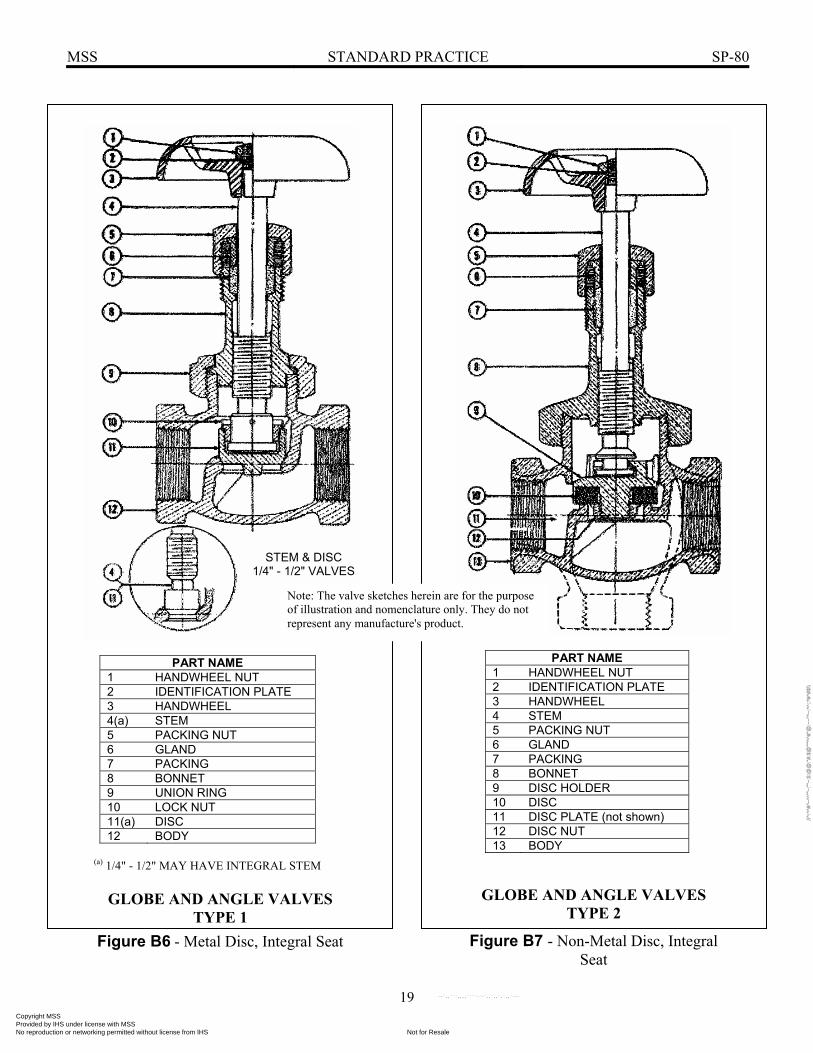
PART NAME 1 HANDWHEEL NUT 2 IDENTIFICATION PLATE 3 HANDWHEEL 4(a) STEM 5 PACKING NUT 6 GLAND 7 PACKING 8 BONNET 9 UNION RING 10 LOCK NUT 11(a) DISC 12 BODY
(a) 1/4" - 1/2" MAY HAVE INTEGRAL STEM
GLOBE AND ANGLE VALVES
TYPE 1
PART NAME 1 HANDWHEEL NUT 2 IDENTIFICATION PLATE 3 HANDWHEEL 4 STEM 5 PACKING NUT 6 GLAND 7 PACKING 8 BONNET 9 DISC HOLDER 10 DISC 11 DISC PLATE (not shown) 12 DISC NUT 13 BODY
GLOBE AND ANGLE VALVES TYPE 2
Figure B6 - Metal Disc, Integral Seat Figure B7 - Non-Metal Disc, Integral Seat
Note: The valve sketches herein are for the purpose of illustration and nomenclature only. They do not represent any manufacture's product.
STEM & DISC 1/4" - 1/2" VALVES
Copyright MSS Provided by IHS under license with MSS
Not for ResaleNo reproduction or networking permitted without license from IHS
--`,,```,,,,````-`-`,,`,,`,`,,`---
//^:^
^#^~
^^""
~:""
~:$:
@@
:"#:$
@""
"^^#
"@:~
~"^~
:^^:
:*#^
#$\\
MSS STANDARD PRACTICE SP-80
20
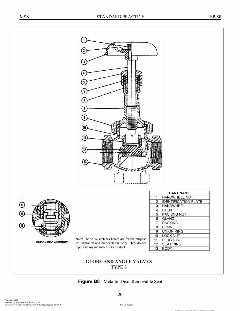
PART NAME 1 HANDWHEEL NUT 2 IDENTIFICATION PLATE 3 HANDWHEEL 4 STEM 5 PACKING NUT 6 GLAND 7 PACKING 8 BONNET 9 UNION RING
10 LOCK NUT 11 PLUG DISC 12 SEAT RING 13 BODY
Figure B8 - Metallic Disc, Removable Seat
GLOBE AND ANGLE VALVES TYPE 3
Note: The valve sketches herein are for the purpose of illustration and nomenclature only. They do not represent any manufacturer's product
Copyright MSS Provided by IHS under license with MSS
Not for ResaleNo reproduction or networking permitted without license from IHS
--`,,```,,,,````-`-`,,`,,`,`,,`---
//^:^^#^~^^""~:""~:$:@@:"#:$@"""^^#"@:~~"^~:^^::*#^#$\\
MSS STANDARD PRACTICE SP-80
21
CHECK VALVE —TYPE 1
Figure B9 - Horizontal Lift Check, Metal to Metal Seat Note: The valve sketches herein are for the purpose of illustration and nomenclature only. They do not represent any manufacturer's product.
CHECK VALVE - TYPE 1
Figure B10 - Angle Lift Check, Metal to Metal Seat
PART NAME 1 CAP 2 UNION RING 3 DISC 4 BODY
PART NAME 1 CAP 2 UNION RING 3 DISC 4 BODY
Copyright MSS Provided by IHS under license with MSS
Not for ResaleNo reproduction or networking permitted without license from IHS
--`,,```,,,,````-`-`,,`,,`,`,,`---
//^:^^#^~^^""~:""~:$:@@:"#:$@"""^^#"@:~~"^~:^^::*#^#$\\

MSS STANDARD PRACTICE SP-80
22
PART NAME 1 CAP OR COVER 2 BODY 3 DISC HOLDER 4 DISC 5 DISC GUIDE NUT
CHECK VALVE TYPE 2
PART NAME 1 BODY 2 DISC HOLDER 3 DISC 4 DISC GUIDE NUT 5 THREADED-IN HUB
CHECK VALVE TYPE 2
Figure B11 - Horizontal and Angle Lift Check Valve Non-Metallic to Metal Seat
Figure B12 - Vertical Lift Check, Non-Metallic to Metal Seat
Note: The valve sketches herein are for the purpose of illustration and nomenclature only. They do not represent any manufacturer's product
Copyright MSS Provided by IHS under license with MSS
Not for ResaleNo reproduction or networking permitted without license from IHS
--`,,```,,,,````-`-`,,`,,`,`,,`---
//^:^^#^~^^""~:""~:$:@@
:"#:$@"""^^#"@
:~~"^~:^^::*#^#$\\

MSS STANDARD PRACTICE SP-80
23
CHECK VALVE TYPE 3
Figure B13 - Swing Check, Metal to Metal Seat Note: The valve sketches herein are for the purpose of illustration and nomenclature only. They do not represent any manufacturer's product.
CHECK VALVE TYPE 4
Figure B14 - Swing Check, Non-Metallic to Metal Seat
PART NAME 1 CAP 2 STOP PLUG 3 SIDE PLUGS 4 HANGER PIN 5 HANGER 6 RETAINING RING 7 WASHER 8 DISC 9 BODY (a)
(a) Body of "Y" type design also acceptable
PART NAME 1 CAP 2 SIDE PLUGS 3 HANGER PIN 4 HANGER 5 DISC HOLDER 6 DISC 7 HANGER NUT 8 DISC NUT 9 BODY (a)
(a) Body of "Y" type design also acceptable
Copyright MSS Provided by IHS under license with MSS
Not for ResaleNo reproduction or networking permitted without license from IHS
--`,,```,,,,````-`-`,,`,,`,`,,`---
//^:^^#^~^^""~:""~:$:@@
:"#:$@"""^^#"@
:~~"^~:^^::*#^#$\\
MSS STANDARD PRACTICE SP-80
24
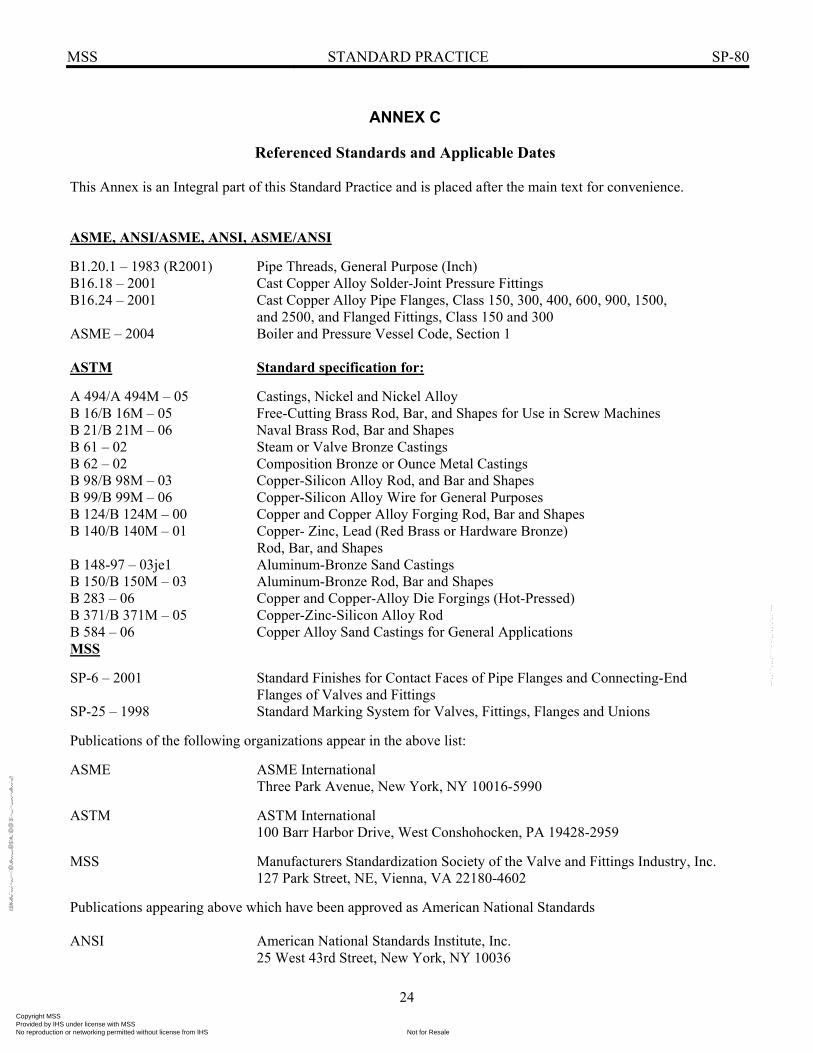
ANNEX C
Referenced Standards and Applicable Dates This Annex is an Integral part of this Standard Practice and is placed after the main text for convenience. ASME, ANSI/ASME, ANSI, ASME/ANSI B1.20.1 – 1983 (R2001) Pipe Threads, General Purpose (Inch) B16.18 – 2001 Cast Copper Alloy Solder-Joint Pressure Fittings B16.24 – 2001 Cast Copper Alloy Pipe Flanges, Class 150, 300, 400, 600, 900, 1500, and 2500, and Flanged Fittings, Class 150 and 300 ASME – 2004 Boiler and Pressure Vessel Code, Section 1 ASTM Standard specification for: A 494/A 494M – 05 Castings, Nickel and Nickel Alloy B 16/B 16M – 05 Free-Cutting Brass Rod, Bar, and Shapes for Use in Screw Machines B 21/B 21M – 06 Naval Brass Rod, Bar and Shapes B 61 – 02 Steam or Valve Bronze Castings B 62 – 02 Composition Bronze or Ounce Metal Castings B 98/B 98M – 03 Copper-Silicon Alloy Rod, and Bar and Shapes B 99/B 99M – 06 Copper-Silicon Alloy Wire for General Purposes B 124/B 124M – 00 Copper and Copper Alloy Forging Rod, Bar and Shapes B 140/B 140M – 01 Copper- Zinc, Lead (Red Brass or Hardware Bronze) Rod, Bar, and Shapes B 148-97 – 03je1 Aluminum-Bronze Sand Castings B 150/B 150M – 03 Aluminum-Bronze Rod, Bar and Shapes B 283 – 06 Copper and Copper-Alloy Die Forgings (Hot-Pressed) B 371/B 371M – 05 Copper-Zinc-Silicon Alloy Rod B 584 – 06 Copper Alloy Sand Castings for General Applications MSS SP-6 – 2001 Standard Finishes for Contact Faces of Pipe Flanges and Connecting-End Flanges of Valves and Fittings SP-25 – 1998 Standard Marking System for Valves, Fittings, Flanges and Unions Publications of the following organizations appear in the above list: ASME ASME International Three Park Avenue, New York, NY 10016-5990 ASTM ASTM International 100 Barr Harbor Drive, West Conshohocken, PA 19428-2959 MSS Manufacturers Standardization Society of the Valve and Fittings Industry, Inc. 127 Park Street, NE, Vienna, VA 22180-4602 Publications appearing above which have been approved as American National Standards ANSI American National Standards Institute, Inc. 25 West 43rd Street, New York, NY 10036
Copyright MSS Provided by IHS under license with MSS
Not for ResaleNo reproduction or networking permitted without license from IHS
--`,,```,,,,````-`-`,,`,,`,`,,`---
//^:^^#^~^^""~:""~:$:@@
:"#:$@"""^^#"@
:~~"^~:^^::*#^#$\\
MSS STANDARD PRACTICE SP-80
25
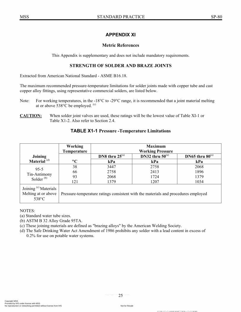
APPENDIX XI
Metric References
This Appendix is supplementary and does not include mandatory requirements.
STRENGTH OF SOLDER AND BRAZE JOINTS Extracted from American National Standard - ASME B16.18. The maximum recommended pressure-temperature limitations for solder joints made with copper tube and cast copper alloy fittings, using representative commercial solders, are listed below. Note: For working temperatures, in the -18°C to -29°C range, it is recommended that a joint material melting at or above 538°C be employed. (c) CAUTION: When solder joint valves are used, these ratings will be the lowest value of Table XI-1 or Table X1-2. Also refer to Section 2.4.
TABLE X1-1 Pressure -Temperature Limitations
Working Temperature
Maximum Working Pressure
DN8 thru 25(a) DN32 thru 50(a) DN65 thru 80(a) Joining Material (d) °C kPa kPa kPa
95-5 Tin-Antimony
Solder (b)
38 66 93
121
3447 2758 2068 1379
2758 2413 1724 1207
2068 1896 1379 1034
Joining (c) Materials Melting at or above
538°C
Pressure-temperature ratings consistent with the materials and procedures employed
NOTES: (a) Standard water tube sizes. (b) ASTM B 32 Alloy Grade 95TA. (c) These joining materials are defined as "brazing alloys" by the American Welding Society. (d) The Safe Drinking Water Act Amendment of 1986 prohibits any solder with a lead content in excess of 0.2% for use on potable water systems.
Copyright MSS Provided by IHS under license with MSS
Not for ResaleNo reproduction or networking permitted without license from IHS
--`,,```,,,,````-`-`,,`,,`,`,,`---
//^:^^#^~^^""~:""~:$:@@:"#:$@"""^^#"@:~~"^~:^^::*#^#$\\

MSS STANDARD PRACTICE SP-80
26
TABLE Xl-2 Pressure -Temperature Ratings
PRESSURE(c) - kPa
CLASS 125 150 200 300 350 PN 20 20 50
END CONN.
THD THD FLG (b) THD THD (e) THD FLG (b) THD
SOLDER(c) SOLDER(c) SOLDER(c) SOLDER(c) - MATERIAL TEMP.(a)
Deg. C ASTM B-62 ASTM B-61
-29 To 66 1379 2068 1551 2758 6895 4137 3447 6895
93 1276 1862 1448 2586 6343 3861 3275 6343 121 1172 1655 1344 2413 5723 3620 3103 5723 149 1069 1448 1241 2231 5102 3378 2930 5171 177 965 1241 1138 2068 4482 3103 2758 4620 204 -- -- -- 1896 3861 2827 2586 4068 208 862 1034 1034 -- -- -- -- -- 232 827(d) 1000(d) -- 1724 3310 2586 2413 3516 260 -- -- -- 1551 2689 2344 2241 2965 288 -- -- -- 1379 2068 2068 2068 2413
NOTES: (a) For lower temperatures, See Section 2.5 (b) P-T Ratings - ASME B16.24 (c) Refer to Section 2.4 for safe P-T rating for solder joint systems. (d) Some codes (I.E. - ASME BPVC, Section 1) Limit the rating temperatures of the indicated material to 208°C. (e) Alternate ratings for valve size DN 6 - DN 50 having threaded ends and union ring body-bonnet joints.
Copyright MSS Provided by IHS under license with MSS
Not for ResaleNo reproduction or networking permitted without license from IHS
--`,,```,,,,````-`-`,,`,,`,`,,`---
//^:^
^#^~
^^""
~:""
~:$:
@@
:"#:$
@""
"^^#
"@:~
~"^~
:^^:
:*#^
#$\\

MSS STANDARD PRACTICE SP-80
27
TABLE XI-3 Minimum Length and Depth of Thread
B
Length of Thread (minimum)
C
Depth of Thread Chamber (a) (minimum)
DN
mm mm 6 6.4 8.9 8 7.1 10.2
10 7.9 10.7 15 9.4 13.7 20 11.2 14.5 25 13.0 17.8 32 15.2 18.0 40 15.8 19.1 50 17.0 20.1 65 20.8 29.0 80 22.4 30.5
Note: (a) Distance parallel to axis from face of valve to nearest point of seat diaphragm wall.
Copyright MSS Provided by IHS under license with MSS
Not for ResaleNo reproduction or networking permitted without license from IHS
--`,,```,,,,````-`-`,,`,,`,`,,`---
//^:^^#^~^^""~:""~:$:@@:"#:$@"""^^#"@:~~"^~:^^::*#^#$\\

MSS STANDARD PRACTICE SP-80
28
TABLE X1-4 Bronze Gate Valves - Diameter of Stem
DIAMETER OF STEM - MINIMUM, mm PN (CLASS)
20 (125)
20 (150)
(200)
50 (300)
(350)
DN
mm mm mm mm mm 8 6.4 7.1 7.9 7.9 7.9
10 7.1 7.1 7.9 7.9 7.9 15 7.9 7.9 8.6 8.6 8.6 20 8.9 8.9 9.7 9.7 9.7 25 9.9 10.2 10.2 10.2 10.2 32 10.7 10.9 11.2 11.2 11.2 40 12.2 12.2 12.7 12.7 12.7 50 13.5 13.5 13.5 13.5 13.5 65 15.0 15.0 15.5 15.5 15.5 80 17.0 17.0 17.8 17.8 17.8
TABLE X1-5 Bronze Globe and Angle Valves - Diameter of Stem
DIAMETER OF STEM - MINIMUM, mm PN (CLASS)
20 (125)
20 (150)
(200)
50 (300)
(350)
DN
mm mm mm mm mm 8 6.1 7.1 7.1 7.1 7.1
10 7.1 7.1 7.1 7.1 7.1 15 7.9 8.9 8.4 8.4 8.4 20 8.9 9.9 10.2 10.2 10.2 25 9.9 10.9 11.2 11.2 11.2 32 10.7 12.5 12.7 12.7 12.7 40 12.5 13.5 13.5 13.5 13.5 50 13.5 15.0 15.8 15.8 15.8 65 15.0 17.0 17.0 17.0 17.0 80 17.0 19.0 19.1 19.1 19.1
Copyright MSS Provided by IHS under license with MSS
Not for ResaleNo reproduction or networking permitted without license from IHS
--`,,```,,,,````-`-`,,`,,`,`,,`---
//^:^^#^~^^""~:""~:$:@@:"#:$@"""^^#"@:~~"^~:^^::*#^#$\\

MSS STANDARD PRACTICE SP-80
29
TABLE Xl-6 Bronze Gate Valves - Diameter of Handwheel
DIAMETER OF HANDWHEEL - MINIMUM, mm PN (CLASS)
20 (125)
20 (150)
(200)
50 (300)
(350)
DN
mm mm mm mm mm 8 41.2 44.5 50.8 50.8 50.8
10 41.2 44.5 50.8 50.8 50.8 15 47.8 50.8 57.2 57.2 57.2 20 57.2 63.5 63.5 63.5 63.5 25 66.6 66.6 69.9 69.9 69.9 32 76.2 76.2 82.6 82.6 82.6 40 82.6 88.9 92.0 92.0 92.0 50 92.0 101.6 101.6 101.6 101.6 65 111.3 117.4 117.4 117.4 117.4 80 127.0 127.0 139.7 139.7 139.7
When irregular handwheels are furnished, the largest dimension of the shape shall be considered the handwheel diameter.
TABLE Xl-7 Bronze Globe and Angle Valves - Diameter of Handwheel
DIAMETER OF HANDWHEEL - MINIMUM, mm
PN (CLASS) 20
(125) 20
(150)
(200) 50
(300)
(350) DN
mm mm mm mm mm 8 38.1 44.5 44.5 44.5 44.5
10 44.5 50.8 50.8 50.8 50.8 15 50.8 57.2 63.5 63.5 63.5 20 63.5 66.6 69.9 69.9 69.9 25 69.9 76.2 76.2 76.2 76.2 32 76.2 88.9 88.9 88.9 88.9 40 88.9 95.3 101.6 101.6 101.6 50 101.6 111.3 120.7 120.7 120.7 65 120.7 127.0 136.7 136.7 136.7 80 136.7 146.1 152.4 152.4 152.4
When irregular handwheels are furnished, the largest dimension of the shape shall be considered the handwheel diameter.
Copyright MSS Provided by IHS under license with MSS
Not for ResaleNo reproduction or networking permitted without license from IHS
--`,,```,,,,````-`-`,,`,,`,`,,`---
//^:^
^#^~
^^""
~:""
~:$:
@@
:"#:$
@""
"^^#
"@:~
~"^~
:^^:
:*#^
#$\\
MSS STANDARD PRACTICE SP-80
30
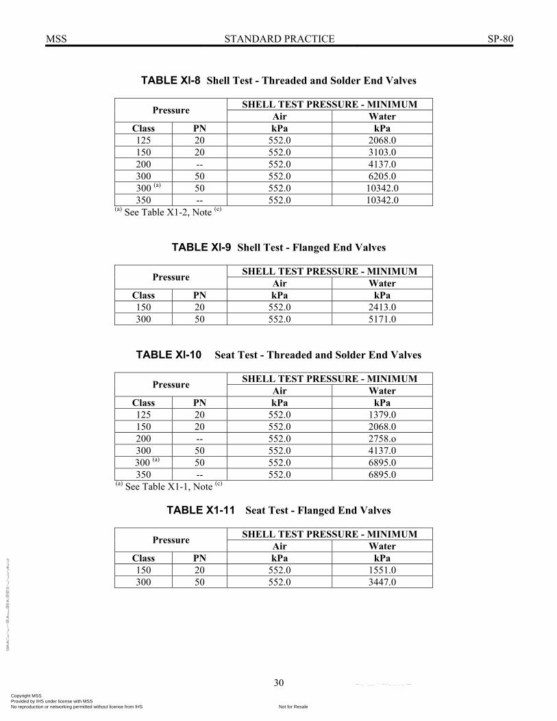
TABLE Xl-8 Shell Test - Threaded and Solder End Valves
SHELL TEST PRESSURE - MINIMUM Pressure Air Water Class PN kPa kPa 125 20 552.0 2068.0 150 20 552.0 3103.0 200 -- 552.0 4137.0 300 50 552.0 6205.0
300 (a) 50 552.0 10342.0 350 -- 552.0 10342.0
(a) See Table X1-2, Note (e)
TABLE Xl-9 Shell Test - Flanged End Valves
SHELL TEST PRESSURE - MINIMUM Pressure Air Water Class PN kPa kPa 150 20 552.0 2413.0 300 50 552.0 5171.0
TABLE Xl-10 Seat Test - Threaded and Solder End Valves
SHELL TEST PRESSURE - MINIMUM Pressure Air Water Class PN kPa kPa 125 20 552.0 1379.0 150 20 552.0 2068.0 200 -- 552.0 2758.o 300 50 552.0 4137.0
300 (a) 50 552.0 6895.0 350 -- 552.0 6895.0
(a) See Table X1-1, Note (c)
TABLE X1-11 Seat Test - Flanged End Valves
SHELL TEST PRESSURE - MINIMUM Pressure Air Water Class PN kPa kPa 150 20 552.0 1551.0 300 50 552.0 3447.0
Copyright MSS Provided by IHS under license with MSS
Not for ResaleNo reproduction or networking permitted without license from IHS
--`,,```,,,,````-`-`,,`,,`,`,,`---
//^:^^#^~^^""~:""~:$:@@
:"#:$@"""^^#"@
:~~"^~:^^::*#^#$\\

List of MSS Standard Practices (Price List Available Upon Request)
Number SP-6-2007 Standard Finishes for Contact Faces of Pipe Flanges and Connecting-End Flanges of Valves and Fittings SP-9-2008 Spot Facing for Bronze, Iron and Steel Flanges SP-25-2008 Standard Marking System for Valves, Fittings, Flanges and Unions SP-42-2004 Class 150 Corrosion Resistant Gate, Glove, Angle and Check Valves with Flanged and Butt Weld Ends SP-43-2008 Wrought and Fabricated Butt-Welding Fittings for Low Pressure, Corrosion Resistant Applications SP-44-2006 Steel Pipeline Flanges SP-45-2003 (R 08) Bypass and Drain Connections SP-51-2007 Class 150LW Corrosion Resistant Flanges and Cast Flanged Fittings SP-53-1999 (R 07) Quality Standard for Steel Castings and Forgings for Valves, Flanges and Fittings and Other Piping Components - Magnetic Particle Examination Method SP-54-1999 (R 07) Quality Standard for Steel Castings for Valves, Flanges, and Fittings and Other Piping Components - Radiographic Examination Method SP-55-2006 Quality Standard for Steel Castings for Valves, Flanges and Fittings and Other Piping Components - Visual Method for Evaluation of Surface Irregularities SP-58-2002 Pipe Hangers and Supports - Materials, Design and Manufacture SP-60-2004 Connecting Flange Joint Between Tapping Sleeves and Tapping Valves SP-61-2003 Pressure Testing of Steel Valves SP-65-2008 High Pressure Chemical Industry Flanges and Threaded Stubs for Use with Lens Gaskets SP-67-2002a Butterfly Valves SP-68-1997 (R 04) High Pressure Butterfly Valves with Offset Design SP-69-2003 Pipe Hangers and Supports - Selection and Application (ANSI/MSS Edition) SP-70-2006 Gray Iron Gate Valves, Flanged and Threaded Ends SP-71-2005 Gray Iron Swing Check Valves, Flanged and Threaded Ends SP-72-1999 Ball Valves with Flanged or Butt-welding Ends for General Service SP-75-2004 Specification for High Test Wrought Butt Welding Fittings SP-77-1995 (R 00) Guidelines for Pipe Support Contractual Relationships SP-78-2005a Gray Iron Plug Valves, Flanged and Threaded Ends SP-79-2004 Socket-Welding Reducer Inserts SP-80-2008 Bronze Gate, Globe, Angle and Check Valves SP-81-2006a Stainless Steel, Bonnetless, Flanged, Knife Gate Valves SP-83-2006 Class 3000 Steel Pipe Unions, Socket-Welding and Threaded SP-85-2002 Gray Iron Globe & Angle Valves, Flanged and Threaded Ends SP-86-2002 Guidelines for Metric Data in Standards for Valves, Flanges, Fittings and Actuators SP-88-1993 (R 01) Diaphragm Valves SP-89-2003 Pipe Hangers and Supports - Fabrication and Installation Practices SP-90-2000 Guidelines on Terminology for Pipe Hangers and Supports SP-91-1992 (R 96) Guidelines for Manual Operation of Valves SP-92-1999 MSS Valve User Guide SP-93-1999 (R 04) Quality Standard for Steel Castings and Forgings for Valves, Flanges, and Fittings and Other Piping Components - Liquid Penetrant Examination Method SP-94-1999 (R 04) Quality Std for Ferritic and Martensitic Steel Castings for Valves, Flanges, and Fittings and Other Piping Components - Ultrasonic Examination Method SP-95-2006 Swage(d) Nipples and Bull Plugs SP-96-2001 (R 05) Guidelines on Terminology for Valves and Fittings SP-97-2006 Integrally Reinforced Forged Branch Outlet Fittings - Socket Welding, Threaded and Buttwelding Ends SP-98-2001 (R 05) Protective Coatings for the Interior of Valves, Hydrants, and Fittings SP-99-1994 (R 05) Instrument Valves SP-100-2002 Qualification Requirements for Elastomer Diaphragms for Nuclear Service Diaphragm Valves SP-101-1989 (R 01) Part-Turn Valve Actuator Attachment - Flange and Driving Component Dimensions and Performance Characteristics SP-102-1989 (R 01) Multi-Turn Valve Actuator Attachment - Flange and Driving Component Dimensions and Performance Characteristics SP-104-2003 Wrought Copper Solder Joint Pressure Fittings SP-105-1996 (R 05) Instrument Valves for Code Applications SP-106-2003 Cast Copper Alloy Flanges and Flanged Fittings, Class 125, 150 and 300 SP-108-2002 Resilient-Seated Cast-Iron Eccentric Plug Valves SP-109-1997 (R 06) Welded Fabricated Copper Solder Joint Pressure Fittings SP-110-1996 Ball Valves Threaded, Socket-Welding, Solder Joint, Grooved and Flared Ends SP-111-2001 (R 05) Gray-Iron and Ductile-Iron Tapping Sleeves SP-112-1999 (R 04) Quality Standard for Evaluation of Cast Surface Finishes -Visual and Tactile Method. This SP must be sold with a 10-surface, three Dimensional Cast Surface Comparator, which is a necessary part of the Standard. Additional Comparators may be sold separately. SP-113-2001 (R 07) Connecting Joint between Tapping Machines and Tapping Valves SP-114-2007 Corrosion Resistant Pipe Fittings Threaded and Socket Welding, Class 150 and 1000 SP-115-2006 Excess Flow Valves, 1 1/4 NPS and Smaller, for Fuel Gas Service SP-116-2003 Service Line Valves and Fittings for Drinking Water Systems SP-117-2006 Bellows Seals for Globe and Gate Valves SP-118-2007 Compact Steel Globe & Check Valves - Flanged, Flangeless, Threaded & Welding Ends (Chemical & Petroleum Refinery Service) SP-119-2003 Factory-Made Belled End Socket Welding Fittings SP-120-2006 Flexible Graphite Packing System for Rising Stem Steel Valves (Design Requirements) SP-121-2006 Qualification Testing Methods for Stem Packing for Rising Stem Steel Valves SP-122-2005 Plastic Industrial Ball Valves SP-123-1998 (R 06) Non-Ferrous Threaded and Solder-Joint Unions for Use with Copper Water Tube SP-124-2001 Fabricated Tapping Sleeves SP-125-2000 Gray Iron and Ductile Iron In-Line, Spring-Loaded, Center-Guided Check Valves SP-126-2007 Steel In-Line Spring-Assisted Center Guided Check Valves SP-127-2001 Bracing for Piping Systems Seismic-Wind-Dynamic Design, Selection, Application SP-128-2006 Ductile Iron Gate Valves SP-129-2003 (R 07) Copper-Nickel Socket-Welding Fittings and Unions SP-130-2003 Bellows Seals for Instrument Valves SP-131-2004 Metallic Manually Operated Gas Distribution Valves SP-132-2004 Compression Packing Systems for Instrument Valves SP-133-2005 Excess Flow Valves for Low Pressure Fuel Gas Appliances SP-134-2006a Valves for Cryogenic Service Including Requirements for Body/Bonnet Extensions SP-135-2006 High Pressure Steel Knife Gate Valves SP-136-2007 Ductile Iron Swing Check Valves SP-137-2007 Quality Standard for Positive Material Identification of Metal Valves, Flanges, Fittings, and Other Piping Components (R-YEAR) Indicates year standard reaffirmed without substantive changes A large number of former MSS Practices have been approved by the ANSI or ANSI Standards, published by others. In order to maintain a single source of authoritative information, the MSS withdraws its Standard Practices in such cases.
Manufacturers Standardization Society of the Valve and Fittings Industry, Inc. 127 Park Street, N.E., Vienna, VA 22180-4620 (703) 281-6613 • Fax # (703) 281-6671
MSS-IHS SP Copyright MSS
Provided by IHS under license with MSSNot for ResaleNo reproduction or networking permitted without license from IHS
--`,,```,,,,````-`-`,,`,,`,`,,`---
//^:^^#^~^^""~:""~:$:@@
:"#:$@"""^^#"@
:~~"^~:^^::*#^#$\\