Brocade DCX 8510-4 Backbone Hardware Installation Guide
174
Brocade DCX 8510-4 Backbone Hardware Installation Guide Hardware Installation Guide 2 June 2020 53-1002177-19 2 June 2020 Broadcom
Transcript of Brocade DCX 8510-4 Backbone Hardware Installation Guide

Brocade DCX 8510-4 Backbone Hardware Installation Guide
Hardware Installation Guide2 June 2020
53-1002177-192 June 2020
Broadcom

Copyright © 2020 Broadcom. All Rights Reserved. Broadcom, the pulse logo, Brocade, the stylized B logo, Fabric OS,and SANnav are among the trademarks of Broadcom in the United States, the EU, and/or other countries. The term“Broadcom” refers to Broadcom Inc. and/or its subsidiaries.
Broadcom reserves the right to make changes without further notice to any products or data herein to improve reliability,function, or design. Information furnished by Broadcom is believed to be accurate and reliable. However, Broadcom doesnot assume any liability arising out of the application or use of this information, nor the application or use of any product orcircuit described herein, neither does it convey any license under its patent rights nor the rights of others.
The product described by this document may contain open source software covered by the GNU General Public Licenseor other open source license agreements. To find out which open source software is included in Brocade products, to viewthe licensing terms applicable to the open source software, and to obtain a copy of the programming source code, pleasedownload the open source disclosure documents in the Broadcom Customer Support Portal (CSP). If you do not have aCSP account or are unable to log in, please contact your support provider for this information.
Broadcom

53-1002177-19 Hardware Installation Guide Brocade DCX 8510-4 Backbone Hardware Installation Guide
Table of Contents
About This Document..........................................................................................................................9What’s new in this document......................................................................................................................................... 9Supported hardware and software.................................................................................................................................9Notes, Cautions, and Danger Notices........................................................................................................................... 9Contacting Technical Support for Your Brocade
® Product......................................................................................... 9
Document Feedback...................................................................................................................................................... 10Product Overview...............................................................................................................................11
Product features............................................................................................................................................................. 11Hardware components...................................................................................................................................................11
Port side view of the device..................................................................................................................................... 13Nonport side view of the device............................................................................................................................... 14
Supported blades........................................................................................................................................................... 15Chassis slots numbering.............................................................................................................................................. 16Port numbering...............................................................................................................................................................17High availability.............................................................................................................................................................. 18Reliability......................................................................................................................................................................... 18Serviceability...................................................................................................................................................................18Software features........................................................................................................................................................... 19Security............................................................................................................................................................................19Network manageability.................................................................................................................................................. 20
Preparing for the Installation............................................................................................................21Installation and safety considerations.........................................................................................................................21
Danger-laser Shared................................................................................................................................................. 21Time and items required............................................................................................................................................... 22Items included with the device.....................................................................................................................................23
Mounting the Device..........................................................................................................................25Mounting options........................................................................................................................................................... 25Mounting precautions.................................................................................................................................................... 25Unpacking, transporting, and installing the device................................................................................................... 26Installing the 8U Chassis Mid-Mount Rack Kit for Two-Post Racks (XBR-DCX4S-0126 and XBR-X64-0126)........ 27
Time and Items Required......................................................................................................................................... 27Parts List................................................................................................................................................................... 27Assembling the Rack Hardware............................................................................................................................... 30Installing the device in the rack................................................................................................................................32
Installing the 8U Chassis Airflow Diversion or Port-Side Exhaust Kit for Four-Post Racks (XBR-DCX4S-0121and XBR-DCX4S-0130)................................................................................................................................................... 34
53-1002177-193
Broadcom

53-1002177-19 Hardware Installation Guide Brocade DCX 8510-4 Backbone Hardware Installation Guide
Time and Items Required......................................................................................................................................... 35Installing the Device in an 18–24-Inch Rack (XBR-DCX4S-0130)...........................................................................35
Parts list............................................................................................................................................................. 35Torque requirements.......................................................................................................................................... 37Assembling the rack hardware.......................................................................................................................... 37Installing the device in the rack.........................................................................................................................42
Installing the Device in a 27-31-Inch Rack (XBR-DCX4S-0121)..............................................................................43Parts list............................................................................................................................................................. 44Torque requirements.......................................................................................................................................... 45Assembling the rack hardware.......................................................................................................................... 46Installing shipping brackets (optional)............................................................................................................... 49Installing the device in the rack.........................................................................................................................49
Installing the 8U Chassis 27-31-Inch Rail Rack Kit for Four-Post Racks (XBR-DCX4S-0120)................................50Time and Items Required......................................................................................................................................... 51Parts List................................................................................................................................................................... 51Assembling the Rack Hardware............................................................................................................................... 52Installing the Device in the Rack..............................................................................................................................54
Cable Management.............................................................................................................................56Requirements and precautions.................................................................................................................................... 56Cable types supported on the FC16-64 port blade.................................................................................................... 56Installing inter-chassis links (ICLs)..............................................................................................................................57
Possible ICL configurations...................................................................................................................................... 59Using Brocade 2 km LWL QSFPs............................................................................................................................ 62
Qualified cables for the FC8-64 port blade................................................................................................................. 63High-density cabling for the FC8-64 port blade......................................................................................................... 64
Initial Configuration........................................................................................................................... 66Items required.................................................................................................................................................................66Providing power to the device..................................................................................................................................... 66Configuring the device.................................................................................................................................................. 67Establishing a serial connection to the device.......................................................................................................... 68Logging in to the serial console port..........................................................................................................................69Configuring the IP addresses.......................................................................................................................................70Logging off the serial console port and disconnecting the serial cable................................................................. 71Establishing an Ethernet connection to the device................................................................................................... 72Customizing a switch name..........................................................................................................................................72Customizing a chassis name........................................................................................................................................72Setting the domain ID....................................................................................................................................................73Setting the date and time..............................................................................................................................................73
Setting the date.........................................................................................................................................................73
53-1002177-194
Broadcom

53-1002177-19 Hardware Installation Guide Brocade DCX 8510-4 Backbone Hardware Installation Guide
Setting the time zone................................................................................................................................................74Synchronizing local time........................................................................................................................................... 74
Determining installed software licenses..................................................................................................................... 75Installing transceivers and attaching cables.............................................................................................................. 75
Installing SFP+ and mSFP transceivers and cables................................................................................................ 75Qualified transceivers for the FC16-64 and CR16-x blades.................................................................................... 76Installing QSFP transceivers and cables..................................................................................................................76
Managing cables.............................................................................................................................................................78Verifying correct operation and backing up the configuration.................................................................................79Powering off the chassis.............................................................................................................................................. 80
System Monitoring............................................................................................................................. 81Monitoring overview.......................................................................................................................................................81Determining the status of a port, application, or extension blade........................................................................... 85
FC8-32E port blade LEDs........................................................................................................................................ 85FC8-48E port blade LEDs........................................................................................................................................ 86FC8-64 port blade LEDs...........................................................................................................................................86FC16-32 port blade LEDs.........................................................................................................................................87FC16-48 port blade LEDs.........................................................................................................................................87FC16-64 port blade LEDs.........................................................................................................................................88FS8-18 encryption blade LEDs.................................................................................................................................88FX8-24 extension blade LEDs..................................................................................................................................89Port, application, and extension blade power LED description................................................................................89Port blade status LED description............................................................................................................................ 89FC ports status LED description...............................................................................................................................90GbE and 10-GbE ports status LED description....................................................................................................... 91
Determining the status of a control processor blade (CP8)..................................................................................... 92Determining the status of a core switch blade (CR16-4)...........................................................................................93Determining the status of a power supply..................................................................................................................94Determining the status of a blower assembly............................................................................................................95Determining the status of a WWN card.......................................................................................................................96
Removal and Replacement Procedures.......................................................................................... 99Introduction..................................................................................................................................................................... 99ESD precautions.............................................................................................................................................................99Chassis door removal and replacement......................................................................................................................99
Time and items required........................................................................................................................................... 99Removing a chassis door......................................................................................................................................... 99Replacing a chassis door....................................................................................................................................... 100
Vertical cable management fingers removal and replacement............................................................................... 100Time and items required......................................................................................................................................... 100
53-1002177-195
Broadcom

53-1002177-19 Hardware Installation Guide Brocade DCX 8510-4 Backbone Hardware Installation Guide
Removing a cable management finger assembly.................................................................................................. 101Replacing a cable management finger assembly...................................................................................................101
Port and application blade removal and replacement............................................................................................. 101Time and items required......................................................................................................................................... 102Removing a blade................................................................................................................................................... 102Replacing a blade................................................................................................................................................... 104Blade filler panel removal and replacement........................................................................................................... 105
Blade filler panel removal and replacement............................................................................................................. 105Removing a filler panel........................................................................................................................................... 105Replacing a filler panel........................................................................................................................................... 106
Control processor blade (CP8) removal and replacement...................................................................................... 106Time and items required......................................................................................................................................... 107Faulty CP blade indicators......................................................................................................................................107Recording critical device information...................................................................................................................... 107Power-up procedure................................................................................................................................................109
Removing a control processor blade (CP8).................................................................................................... 109Replacing a control processor blade (CP8).................................................................................................... 110
Power-down procedure........................................................................................................................................... 111Verifying operation of the new CP blade................................................................................................................112
Downloading firmware from an FTP server.................................................................................................... 113Downloading firmware from a USB device..................................................................................................... 115
Completing the replacement................................................................................................................................... 119Core switch blade (CR16-x) removal and replacement........................................................................................... 120
Time and items required......................................................................................................................................... 120Faulty core switch blade indicators........................................................................................................................ 120Removing a core switch blade (CR16-x)................................................................................................................120Replacing a core switch blade (CR16-x)................................................................................................................121
Power supply removal and replacement...................................................................................................................122Time and items required......................................................................................................................................... 122Identifying power supplies.......................................................................................................................................122Removing a power supply...................................................................................................................................... 123Replacing a power supply...................................................................................................................................... 124
Blower assembly removal and replacement............................................................................................................. 124Time and items required......................................................................................................................................... 124Removing a blower assembly.................................................................................................................................125Replacing a blower assembly.................................................................................................................................125
WWN card removal and replacement........................................................................................................................ 125Time and items required......................................................................................................................................... 126Using the wwnrecover utility..................................................................................................................................126Verifying the need for replacement.........................................................................................................................127
53-1002177-196
Broadcom

53-1002177-19 Hardware Installation Guide Brocade DCX 8510-4 Backbone Hardware Installation Guide
Preparing for WWN card replacement................................................................................................................... 128Hot-swap replacement............................................................................................................................................ 128Power-down replacement........................................................................................................................................129Removing the WWN card and WWN bezel (logo plate)........................................................................................ 131
Transceiver and fiber optic cable removal and replacement.................................................................................. 134Time and items required......................................................................................................................................... 135Items required......................................................................................................................................................... 135Removing an SFP+ transceiver..............................................................................................................................135Replacing an SFP+ transceiver.............................................................................................................................. 136Removing and replacing an mSFP optical transceiver and cable..........................................................................137
Removing an mSFP transceiver......................................................................................................................137Replacing an mSFP transceiver......................................................................................................................137
Removing and replacing a QSFP and cable..........................................................................................................137Qualified transceivers for the FC16-64 and CR16-x blades........................................................................... 138Removing a QSFP transceiver and cable.......................................................................................................138Replacing a QSFP transceiver and cable....................................................................................................... 139
Chassis removal and replacement........................................................................................................................... 140Time and items required......................................................................................................................................... 140Faulty chassis indicators.........................................................................................................................................141Recording critical device and SAN information...................................................................................................... 141Disconnecting from network and fabric.................................................................................................................. 145Removing components from the chassis................................................................................................................145Installing the replacement chassis..........................................................................................................................146Installing components into the chassis...................................................................................................................146Downloading the configuration................................................................................................................................147Reconnecting the system to the network and fabric.............................................................................................. 148Verifying correct operation of system..................................................................................................................... 149Verifying correct configuration of the fabric............................................................................................................ 150Cable routing table..................................................................................................................................................151
Application and Encryption Blades............................................................................................... 154Introduction................................................................................................................................................................... 154FS8-18 blade................................................................................................................................................................. 154FX8-24 blade................................................................................................................................................................. 154
Port Numbering Templates............................................................................................................. 156CR16-4 core blade port numbering............................................................................................................................156FC8-32E port blade port numbering.......................................................................................................................... 156FC8-48E port blade port numbering.......................................................................................................................... 157FC8-64 port blade port numbering.............................................................................................................................157FC16-32 port blade port numbering...........................................................................................................................158
53-1002177-197
Broadcom

53-1002177-19 Hardware Installation Guide Brocade DCX 8510-4 Backbone Hardware Installation Guide
FC16-48 port blade port numbering...........................................................................................................................158FC16-64 port blade port numbering...........................................................................................................................158FS8-18 encryption blade port numbering..................................................................................................................159FX8-24 extension blade port numbering................................................................................................................... 159
Diagnostics and Troubleshooting.................................................................................................. 160Introduction................................................................................................................................................................... 160Obtaining chassis and component status................................................................................................................ 160Interpreting POST and boot results...........................................................................................................................161
POST....................................................................................................................................................................... 161Boot......................................................................................................................................................................... 161
Diagnostics....................................................................................................................................................................161Troubleshooting............................................................................................................................................................162
Regulatory Statements.................................................................................................................... 165BSMI Statement (Taiwan).............................................................................................................................................165Canadian Requirements.............................................................................................................................................. 165CE Statement................................................................................................................................................................ 165China ROHS.................................................................................................................................................................. 166FCC Warning (U.S. Only).............................................................................................................................................166Germany statement...................................................................................................................................................... 166KCC Statement (Republic of Korea).......................................................................................................................... 166VCCI Statement.............................................................................................................................................................167
Caution and Danger Notices...........................................................................................................168Cautions.........................................................................................................................................................................168Danger Notices............................................................................................................................................................. 169
Danger-laser Shared............................................................................................................................................... 171
Revision History............................................................................................................................... 173
53-1002177-198
Broadcom

53-1002177-19 Hardware Installation Guide Brocade DCX 8510-4 Backbone Hardware Installation Guide
About This Document
What’s new in this documentStarting with this release, all new and modified content is listed in the "Revision History" section at the end of thisdocument.
Supported hardware and softwareThis document includes information specific to the Brocade DCX 8510-4 running Brocade Fabric OS version 7.4.0 andlater.
Notes, Cautions, and Danger NoticesNotes, cautions, and danger statements may be used in this document.
NOTEA Note provides a tip, guidance, or advice, emphasizes important information, or provides a reference to relatedinformation.
CAUTIONA Caution statement alerts you to situations that can be potentially hazardous to you or cause damage tohardware, firmware, software, or data.
DANGERA Danger statement indicates conditions or situations that can be potentially lethal or extremely hazardous toyou. Safety labels are also attached directly to products to warn of these conditions or situations.
Contacting Technical Support for Your Brocade® ProductFor product support information and the latest information on contacting the Technical Assistance Center, go to https://www.broadcom.com/support/fibre-channel-networking/. If you have purchased Brocade
® product support directly from
Broadcom, use one of the following methods to contact the Technical Assistance Center 24x7.
Online Telephone
For nonurgent issues, the preferred method is to log in tomyBroadcom at https://www.broadcom.com/mybroadcom. (Youmust initially register to gain access to the Customer SupportPortal.) Once there, select Customer Support Portal > SupportPortal. You will now be able to navigate to the following sites:• Knowledge Search: Clicking the top-right magnifying glass
brings up a search bar.• Case Management: The legacy MyBrocade case
management tool (MyCases) has been replaced with the FibreChannel Networking case management tool.
• DocSafe: You can download software and documentation.• Other Resources: Licensing Portal (top), SAN Health (top and
bottom), Communities (top), Education (top).
Required for Severity 1 (critical) issues:Please call Fibre Channel Networking Global Support at one ofthe numbers listed at https://www.broadcom.com/support/fibre-channel-networking/.
If you purchased Brocade product support from a Broadcom OEM/solution provider, contact your OEM/solution providerfor all your product support needs.
53-1002177-199
Broadcom

53-1002177-19 Hardware Installation Guide Brocade DCX 8510-4 Backbone Hardware Installation Guide
• OEM/solution providers are trained and certified by Broadcom to support Brocade products.• Broadcom provides backline support for issues that cannot be resolved by the OEM/solution provider.• Brocade Supplemental Support augments your existing OEM support contract, providing direct access to Brocade
expertise. For more information on this option, contact Broadcom or your OEM.• For questions regarding service levels and response times, contact your OEM/solution provider.
Document FeedbackQuality is our first concern. We have made every effort to ensure the accuracy and completeness of this document.However, if you find an error or an omission or if you think that a topic needs further development, we want to hear fromyou. Send your feedback to [email protected]. Provide the publication title, publication number, topicheading, page number, and as much detail as possible.
53-1002177-1910
Broadcom

53-1002177-19 Hardware Installation Guide Brocade DCX 8510-4 Backbone Hardware Installation Guide
Product Overview
Product featuresKey product features include the following:
• Up to 256 16-Gbps external ports in a single chassis , enabling high density SAN configurations with reduced footprint.• Support for 2, 4, 8, and 16-Gbps autosensing Fibre Channel ports. Trunking technology groups up to eight ports to
create high performance 128-Gbps ISL trunks between switches.• 10-Gbps FC-type SFPs in 32/48-port 16-Gbps port blades, and 10-GbE SFPs in the FX8-24 application blades. The
two types of SFPs are not interchangeable.• The 10-Gbps ports can be manually configured on only the first eight ports of the 32- and 48-port 16-Gbps port blades.• Support for many of the application, port blade, and control processor (CP) blades supported in the Brocade DCX
family of backbones (with the exception of the Core Switch Blade), thereby providing flexible system configurations andfewer types of new blades.
• Beginning with Fabric OS v7.0.1, up to nine chassis can be connected with the use of 4x16-Gbps quad SFP (QSFP)inter-chassis links (ICLs). Fabric OS v7.0.0 permits up to six chassis to be linked.
• Support for high-performance port blades running at 2, 4, 8, 10, or 16-Gbps, enabling flexible system configuration.• Redundant and hot-swappable control processor and core switch blades, power supplies, blower assemblies, and
WWN cards that enable a high availability platform and enable nondisruptive software upgrades for mission-criticalSAN applications.
• Universal ports that self-configure as E_Ports, F_Ports, EX_Ports and M_Ports (mirror ports). 10-Gbps ports areE_Ports only.
• Diagnostic port (D_Port) functionality.• In-flight data cryptographic (encryption/decryption) and data compression capabilities through the 16-Gbps port blades
when configured as ISLs.• Fibre Channel over IP (FCIP) functionality through the FX8-24 blade.
Hardware componentsThe device has a modular and scalable mechanical construction that allows a wide range of flexibility in installation, fabricdesign, and maintenance. The chassis can be mounted with the cables facing the front of the equipment rack or to therear, and consists of the following:
• Up to four hot-swappable port blade assemblies that can be configured in a single chassis, delivering up to 256 16-Gbps Fibre Channel ports .
• Two slots for control processor blades (CP8):– A single active CP8 blade can control all the ports in the chassis.– The standby CP8 blade assumes control of the chassis if the active CP fails.– The CP blade contains the control plane for the device and hosts the Fabric OS that manages all hardware within
the device.The CP blade provides the following external connections for device configuration, firmware downloads, service,management, and monitoring functions.
• USB port for firmware download and supportsave data.• Serial console RJ45 port.• An 10/100/1000Base-T RJ45 Ethernet port for device management and configuration. This is an auto-sensing MDI
port.• An 10/100/1000Base-T RJ45 Ethernet port for service. This is an auto-sensing MDI port.
53-1002177-1911
Broadcom

53-1002177-19 Hardware Installation Guide Brocade DCX 8510-4 Backbone Hardware Installation Guide
NOTEDevice control processors and management modules contain batteries for RTC/NVRAM backup. Do notattempt to replace these batteries. Dispose of hardware components containing these batteries as requiredby local ordinances and regulations.
• Two slots for core switch blades (CR16-4):– CR16-4 blade interconnects all port blades.– Inter-chassis link (ICL) connectors to connect to as many as nine neighboring chassis using Fabric OS v7.0.1 or
later. Only six chassis can be connected using Fabric OS v7.0.0.– Both CR16-4 blades are active.
• Modular, hot-swappable port blades:– 32-port, 8-Gbps blades (FC8-32E)– 48-port, 8-Gbps blades (FC8-48E)– 64-port, 8-Gbps blades (FC8-64)– 32-port, 16-Gbps blades (FC16-32)– 48-port, 16-Gbps blades (FC16-48)– 64-port, 16-Gbps blades (FC16-64)
• Modular, hot-swappable application blades:– FX8-24: 24-port (12 FC, 10 1-GbE, and 2 10-GbE) FCIP extension blade enabling long distance communication
over existing IP infrastructure.• Modular, hot-swappable encryption blades:
– FS8-18: 16-port, up to 4 blades per chassis, supporting in-flight data cryptographic (encryption/decryption) anddata-compression capabilities.
• Modular, hot-swappable field-replaceable units (FRUs):– Two blower assemblies.– Two power supplies (100-240 VAC autosensing).
• At 110 VAC (nominal): A minimum of two power supplies is required, regardless of the number of port orapplication blades. This configuration does not support high availability.
• 220 VAC (nominal) is recommended for efficiency. A second power supply is required to support high availability.• Redundant AC primary power connections ensure high availability. Each power supply has its own connector, so
the number of primary power connections is two for optimum efficiency and redundancy.– Two WWN cards.– Blades use small form-factor pluggable (SFP+, mSFP, and QSFP) optical transceivers.
• The 8-Gbps SFP+s and mSFPs auto-negotiate at 2, 4, and 8 Gbps.• The 10-Gbps speed must be manually set and requires special 10-Gbps FC SFP+ transceivers.• The 16-Gbps SFP+ transceivers support speeds of 2, 4, 8, 10, and 16 Gbps.• The 16-Gbps QSFPs supported on FC16-64 port blade and core blades auto-negotiate at 4, 8, and 16 Gbps.• The 16-Gbps fixed-speed QSFPs on the core blades run at 64-Gbps (four fixed 16-Gbps clustered in a single
quad connector and cable).• Blades are serviced from the port side of the chassis. Blowers, power supplies, and power cables are serviced from
the nonport side.• World Wide Name (WWN) cards on the nonport side, with WWN status LEDs located under the bezel.• Two vertical cable management finger assemblies and a redesigned chassis door for improved cable management.
53-1002177-1912
Broadcom

53-1002177-19 Hardware Installation Guide Brocade DCX 8510-4 Backbone Hardware Installation Guide
Port side view of the deviceFigure 1: Port side view of the Brocade DCX 8510-4 (sample configuration)
1. Port blade (FC16-32)2. Core switch blade (CR16-4)3. Control processor blade (CP8)4. Exhaust vent
NOTEAirflow is from the nonport side to the port side and out the exhaust vents. If you use the Port Side Exhaust Kit,the air vents are all on the port side of the chassis.
53-1002177-1913
Broadcom

53-1002177-19 Hardware Installation Guide Brocade DCX 8510-4 Backbone Hardware Installation Guide
Figure 2: Port side view of Brocade DCX 8510-4 with the Airflow Diversion and Port Side Exhaust Kit installed(sample configuration)
Nonport side view of the deviceThe following figure shows a sample configuration of the nonport side view of the Brocade DCX 8510-4.
53-1002177-1914
Broadcom

53-1002177-19 Hardware Installation Guide Brocade DCX 8510-4 Backbone Hardware Installation Guide
Figure 3: Nonport side view of the Brocade DCX 8510-4 (sample configuration)
1. WWN card bezel (logo plate)2. Power supply3. Blower assembly4. Label with serial number and WWN
Supported bladesThe following table summarizes the port, application, control processor, and core switch blades that are supported in thedevice.
53-1002177-1915
Broadcom

53-1002177-19 Hardware Installation Guide Brocade DCX 8510-4 Backbone Hardware Installation Guide
Table 1: Blades available for the device
Description Name Function
Control processor blade CP8 The CP8 blade contains the control plane for the chassis. There are two CP8blades for redundancy. This control processor blade is compatible with theBrocade DCX 8510-8, Brocade DCX 8510-4, Brocade DCX-4S, and BrocadeDCX platforms.
Core switch blade CR16-4 The CR16-4 blade contains the ASICs for switching between port blades. Everyport blade connects to each core switch blade. There can be up to 256 16-Gbpsor 8-Gbps total ports for port blades. Each core switch blade connects to 128backplane ports. Core switch blades have additional front port connectivity toconnect multiple chassis and backplane connections for the storage serverblade. This core switch blade is compatible only with the Brocade DCX 8510-4and requires specific type of QSFP transceivers.
32-port 8-Gbps port blade FC8-32E A 32-port Brocade port blade supporting 2, 4, and 8 Gbps Fibre Channel portspeeds. This port blade is compatible with the Brocade Brocade DCX 8510-8 andBrocade DCX 8510-4 This blade requires Fabric OS v7.0.1 or later to run in thischassis.
48-port 8-Gbps port blade FC8-48E A 48-port Brocade port blade supporting 2, 4, and 8 Gbps Fibre Channel portspeeds. This port blade is compatible with the Brocade DCX 8510-8 and BrocadeDCX 8510-4. This blade requires Fabric OS v7.0.1 or later to run in this chassis.
64-port 8-Gbps port blade FC8-64 A 64-port Brocade port blade supporting 2, 4, and 8 Gbps port speeds withmSFPs. This port blade is compatible with the Brocade DCX 8510-8, BrocadeDCX 8510-4, Brocade DCX-4S, and Brocade DCX platforms.
32-port 16-Gbps port blade FC16-32 A 32-port Brocade port blade supporting 2, 4, 8, 10, and 16 Gbps Fibre Channelport speeds. The blade also supports port-based in-flight encryption/decryptionand compression/decompression. This port blade is compatible with the BrocadeDCX 8510-8 and Brocade DCX 8510-4 and requires Fabric OS v7.0.0 or later torun in this chassis.
48-port 16-Gbps port blade FC16-48 A 48-port Brocade port blade supporting 2, 4, 8, 10, and 16 Gbps Fibre Channelport speeds. The blade also supports port-based in-flight encryption/decryptionand compression/decompression. This port blade is compatible with the BrocadeDCX 8510-8 and Brocade DCX 8510-4 and requires Fabric OS v7.0.0 or later torun in this chassis.
64-port 16-Gbps port blade FC16-64 A 64-port Brocade port blade supporting 4, 8, and 16-Gbps Fibre Channel portspeeds. The blade also supports port-based in-flight encryption/decryption andcompression/decompression. This port blade is compatible with the BrocadeDCX 8510-8 and Brocade DCX 8510-4 and requires Fabric OS v7.3.0 or later torun in this chassis. Requires specific type of QSFP transceivers.
Storage encryption blade FS8-18 The FS8-18 blade enables data cryptographic (encryption/decryption) anddata-compression capabilities for data-at-rest. It has 16 Fibre Channel opticalSFP ports. This application blade is compatible with the Brocade DCX 8510-8,Brocade DCX 8510-4, Brocade DCX-4S, and Brocade DCX platforms andrequires Fabric OS v7.0.0 or later to run in the 8510-4 and 8510-8 chassis.
FCIP extension blade FX8-24 The FX8-24 blade enables FCIP functionality over existing IP infrastructure.It has 12 FC ports, 10 1-GbE ports, and two 10-GbE ports available. Thisapplication blade is compatible with the Brocade DCX 8510-8, Brocade DCX8510-4, Brocade DCX-4S, and Brocade DCX platforms and requires Fabric OSv7.0.0 or later to run in the DCX 8510-4 and DCX 8510-8 chassis.
Chassis slots numberingThe chassis slots are numbered and used for the following purpose.
53-1002177-1916
Broadcom

53-1002177-19 Hardware Installation Guide Brocade DCX 8510-4 Backbone Hardware Installation Guide
• Numbered 1 through 8, from bottom to top when facing the port side of the Brocade DCX 8510-4.• Slots 4 and 5 can be used only to install the control processor blades (CP8).• Slots 3 and 6 can be used only to install the core switch blades (CR16-4).• Slots 1-2 and 7-8 can be filled with port, application, or encryption blades.• Unused slots must be filled with blade filler panels to maintain adequate cooling.
Port numberingThe device uses the following port numbering method.
Table 2: Port numbering and trunking port groups
Blade Port numbering Trunking port groups
CR16-4 core blade 0 through 7 from right to left. • Trunk group 0: QSFP ports 0-3• Trunk group 1: QSFP ports 4-7
Each connector is a group of four 16-Gbpsports. For supported QSFPs, refer to Qualifiedtransceivers for FC16-64 port bladeIndividual FC ports within the same QSFP portcannot form a trunk. A trunk has to comprise ofindividual FC ports from different consecutiveQSFP ports. Only four FC ports from consecutiveQSFP ports can form a trunk in Brocade DCX8510-4
FC8-32E port blade • 0 through 15 from right to left on the lower set of ports• 16 through 31 from right to left on the upper set of
ports.
Trunk groups: 0-7, 8-15, 16-23, and 24-31.
FC8-48E port blade • 0 through 23 from right to left on the lower set of ports• 24 through 47 from right to left on the upper set of
ports.
Trunk groups: 0-7, 8-15, 16-23, 24-31, 32-39, and40-47.
FC8-64 port blade • 0 through 31 from right to left on the lower set ofports.
• 32 through 63 from right to left on the upper set ofports.
Trunk groups: 0-7, 8-15, 16-23, 24-31, 32-39, 40-47,48-55, and 56-63.
FC16-32 port blade • 0 through 15 from right to left on the lower set ofports.
• 16 through 31 from right to left on the upper set ofports.
Trunk groups: 0-7, 8-15, 16-23, and 24-31.
FC16-48 port blade • 0 through 23 from right to left on the lower set ofports.
• 24 through 47 from right to left on the upper set ofports.
Trunk groups: 0-7, 8-15, 16-23, 24-31, 32-39, and40-47.
FC16-64 port blade • 0 through 63 from right to left. Trunk groups: 0-7, 8-15, 16-23, 24-31, 32-39, 40-47,48-55, and 56-63.These are QSFP ports 0-15. For supported QSFPs,refer to Qualified transceivers for FC16-64 portblade.
FS8-18 blade • 16 FC ports: 0 through 15 from right to left.• Two 10/100/1000 BaseT ports: GE0 and GE1 from
right to left.
• Trunk group 0: FC ports 0-7• Trunk group 1: FC ports 8-15
53-1002177-1917
Broadcom

53-1002177-19 Hardware Installation Guide Brocade DCX 8510-4 Backbone Hardware Installation Guide
Blade Port numbering Trunking port groups
FX8-24 blade • FC ports labeled FC on the front panel: 0 through 11in two horizontal rows of six ports starting from thelower right and upper right in the right group of 12ports.
• Two 10-GbE ports labeled 10GE on the front panel: 0and 1 in the lower row to the left of the FC ports.
• 1-GbE ports labeled GE on the front panel: 0 through9 in both rows to the left of the FC and 10GE ports.
• Trunk group 0: FC ports 0-1• Trunk group 1: FC ports 6-7• Trunk group 2: FC ports 2-5 and 8-11
High availabilityThe following features contribute to the high availability the device:
• Redundant, hot-swappable FRUs, including blades, power supplies, blowers, and WWN cards• Enhanced data integrity on all data paths• Fabric Shortest Path First (FSPF) rerouting around failed links• Integration with Simple Network Management Protocol (SNMP) managers• Automatic control processor failover• Nondisruptive "hot" software code loads and activation• Easy configuration, save, and restore
The high availability software architecture provides a common framework for all applications that reside on the system,allowing global and local states to be maintained through any component failure. High availability elements consist of theHigh Availability Manager, the heartbeat, the fault/health framework, the replicated database, initialization, and softwareupgrade.
The High Availability Manager controls access to the standby control processor, facilitates software upgrades, preventsextraneous CP failover activity, closes and flushes streams, provides flow control and message buffering, and supports acentralized active and standby state.
ReliabilityThe device uses the following error detection and correction mechanisms to ensure reliability of data:
• Error Detection and Correction over main control processor memory.• Error Detection and Correction mechanism, which checks for encoder errors and fault isolation (EDFI), such as cyclic
redundancy checking (CRC), parity checking, checksum, and illegal address checking.• Power-on self-test (POST).• Dual control processors that enable hot, nondisruptive fast firmware upgrades.• One serial port and two Ethernet ports (on each control processor) for management and for service. Offline control
processor diagnostics and remote diagnostics simplify troubleshooting. The standby control processor monitorsdiagnostics to ensure the system is operational should a failover be necessary.
• Bus monitoring and control of blades and other field-replaceable units (FRUs).
ServiceabilityThe device provides the following features to enhance and ensure serviceability:
53-1002177-1918
Broadcom

53-1002177-19 Hardware Installation Guide Brocade DCX 8510-4 Backbone Hardware Installation Guide
• Modular design with hot-swappable components.• Flash memory that stores two firmware images per control processor.• USB port on control processor blades for most tasks that formerly required an FTP/SCP server, including software and
firmware upgrades.• Nonvolatile random-access memory (NVRAM), containing the OEM serial number, Brocade serial number, revision
information, and part number information.• Background health-check daemon.• Memory scrubber, self test, and bus ping to determine if a bus is not functioning.• RASlog messages.• SMI-S compliant.• Hardware and software watchdog timers.• Status LEDs.• Predictive diagnostics analysis through Fabric Watch.• SNMP (including version 3) integration with higher-layer managers.
Software featuresThe Fabric OS allows any Fibre Channel-compliant device to attach to the switches as long as it conforms to the devicelogin, name service, and related Fibre Channel standards. Each operating environment requires that a Fibre Channel hostbus adapter (HBA) be available with a standards-compliant driver for correct interface to the fabric.
Fabric OS consists of a set of embedded applications running on top of an embedded Linux operating system kernel.Some of these applications include:
• Name server• Alias server• Zone server• Simple Network Management Protocol (SNMP) agent• SMI-S compliant API• Syslog auditing• Reliable Commit Service (RCS)• NTP• Tasks to manage address assignment, routing, link initialization, fabric initialization, link shutdown, the device
shutdown, and the user interface
SecurityThe following list highlights some of the key security features available in the device and in other Brocade enterprise-classproducts running Fabric OS 7.0.1 or later. For details, contact your device supplier and refer to the Brocade White Paper,"The Growing Need for Security in Storage Area Networks."
53-1002177-1919
Broadcom

53-1002177-19 Hardware Installation Guide Brocade DCX 8510-4 Backbone Hardware Installation Guide
• DH-CHAP• SSHv2 (using AES, 3DES, RSA)• HTTPS (using AES)• SNMPv3• FC-SP• Secure RPC• Secure file copy (SCP)• Telnet disable• Telnet timeout• IP filters (block listeners)• Secure passwords (centralized control through RADIUS/CHAP)• Multiple user accounts (MUAs) (Up to 255)• Role-based access controls (RBACs)• Administrative domains/Virtual fabrics• Boot PROM password reset• Password hardening policies• Up front login in Web Tools• Login banner• Monitoring of attempted security breaches (through audit logging)• Monitoring of attempted security breaches (through Fabric Watch Security Class)• Fibre Channel security policies: DCC and SCC• Trusted Switch (FCS) for central security management• Management access controls (SNMPv3, Telnet, FTP, serial port, front panel)• Hardware-enforced zoning by WWN, domain/port ID, or both• Default zoning• RSCN suppression and aggregation• Configurable RSCN suppression by port• NTPv3 (to synchronize timestamps)• Event auditing• Change tracking• Firmware change alerts in Fabric Manager• Persistent port disable• Persistent domain ID• E_Port disable
Network manageabilityThe device has a single domain and is managed as a single element with Brocade Network Advisor. The device respondsto its own IP address and appears as a separate entity to the Telnet protocol and SNMP.
All management interfaces, such as Telnet, Web Tools, standards-compliant SMI-S, and Management Server, support a"port N within blade M" naming scheme.
The device supports SNMPv1 and SNMPv3. When SNMP devices send SNMP messages to a management consolerunning SAN management software, the information is stored in a management information base (MIB). Fabric OS v7.0.0and later supports the latest Fibre Alliance Fibre Channel Management (FCMGMT) and Storage Management Initiative(SMI) MIBs, which allow common information necessary for management software to provide information to a SANadministrator. Refer to the Fabric OS MIB Reference for additional MIB information.
53-1002177-1920
Broadcom

53-1002177-19 Hardware Installation Guide Brocade DCX 8510-4 Backbone Hardware Installation Guide
Preparing for the Installation
Installation and safety considerationsRead the following sections before preparing to install the device.
DANGERUse only optical transceivers that are qualified by Broadcom and comply with the FDA Class 1 radiationperformance requirements defined in 21 CFR Subchapter I, and with IEC 60825 and EN60825. Optical productsthat do not comply with these standards might emit light that is hazardous to the eyes.
• Caution and Danger Notices.• Managing cables and plan for cable management.• Refer to the Brocade DCX 8510 Backbone Technical Specification, power supply specifications section, and plan for
meeting the power supply standards based on your device configuration.
Follow these steps to ensure correct installation and operation.
1. Ensure that dedicated electrical branch circuits with the following characteristics are available:
• 200 - 240 VAC, 50-60 Hz, two branch circuits are recommended for high availability and maximum blade usagewhen configured with 192 or more 16-Gbps ports.
• Two cables for 200 - 240 VAC service• Protected by a circuit breaker in accordance with local electrical codes• Supply circuit, line fusing, and wire size adequate to the electrical rating on the chassis nameplate• Location close to the chassis and easily accessible• Grounded outlets installed by a licensed electrician and compatible with the power cords
CAUTIONUse a separate branch circuit for each power cord, which provides redundancy in case one of the circuitsfails.
2. Plan for cable management before installing the chassis.
Cables can be managed in a variety of ways, such as by routing cables below the chassis, to either side of thechassis, through cable channels on the sides of the cabinet, or by using patch panels.
3. Ensure that the following is available for configuration of the device:
• Workstation with an installed terminal emulator, such as HyperTerminal• Serial cable (provided)• Three Ethernet cables (including one spare)• Access to an FTP server for backing up the switch configuration or collecting supportsave output data (optional)• A Brocade USB stick for collecting supportsave output data (optional)• Transceivers (copper and optical) and compatible cables
4. Ensure that the air intake and exhaust vents on the device will have a minimum of 5.1 cm (2 in.) of airspace when thedevice is installed.
5. Ensure that the air temperature on the air intake side of the device will be less than 40°C (104°F) during operationwhen the device is installed.
Danger-laser Shared
53-1002177-1921
Broadcom

53-1002177-19 Hardware Installation Guide Brocade DCX 8510-4 Backbone Hardware Installation Guide
Laser DangersDANGERAll fiber-optic interfaces use Class 1 lasers.
GEFAHR Alle Glasfaser-Schnittstellen verwenden Laser der Klasse 1.DANGER Toutes les interfaces en fibre optique utilisent des lasers de classe 1.PELIGRO Todas las interfaces de fibra óptica utilizan láser de clase 1.
DANGERLaser Radiation. Do Not View Directly with Optical Instruments. Class 1M Laser Products.
GEFAHR Laserstrahlung! Schauen Sie nicht direkt mit optischen Instrumenten in den Laserstrahl herein. Klasse 1MLaserprodukte.
DANGER Rayonnement de laser. Ne regardez pas directement avec des instruments optiques. Produits de laser declasse 1M.
PELIGRO Radiacion de Laser. No vea directamente con Instrumentos Opticos. Clase 1M de Productos de Laser.警告 レーザ放射 光学器具で直接ビームを見ないこと クラス1 M レーザ製品
DANGERUse only optical transceivers that are qualified by Broadcom and comply with the FDA Class 1 radiationperformance requirements defined in 21 CFR Subchapter I, and with IEC 60825 and EN60825. Optical productsthat do not comply with these standards might emit light that is hazardous to the eyes.
GEFAHR Verwenden Sie nur optische Transceiver, die von Broadcom zugelassen sind und die die Anforderungengemäß FDA Class 1 Radiation Performance Standards in 21 CFR, Unterkapitel I, sowie IEC 60825 undEN60825 erfüllen. Optische Produkte, die diese Normen nicht erfüllen, können Strahlen aussenden, die für dasmenschliche Auge gefährlich sind.
DANGER Utilisez uniquement des émetteurs-récepteurs optiques certifiés par Broadcom et conformes aux exigencessur la puissance de rayonnement de catégorie 1 de la FDA définies au sous-chapitre 21 CFR I et à les normesIEC 60825 et EN60825. Les produits optiques non-conformes à ces normes sont susceptibles d’émettre unelumière dangereuse pour les yeux.
PELIGRO Utilice sólo transceptores ópticos aprobados por Broadcom y que cumplan con las normas IEC 60825 yEN60825, y con los estándares de rendimiento Clase 1 de FDA definidos en el subcapítulo I de 21 CFR. Losproductos ópticos que no cumplan con estos estándares pueden emitir luz dañina para los ojos.
Time and items requiredThe following table describes the main installation and setup tasks, the estimated time required for each, and the itemsrequired to complete the task for a device that is fully populated with FC16-64 port blades. Configurations with fewerblades or ports require less time. These time estimates assume a prepared installation site and appropriate power andnetwork connectivity.
53-1002177-1922
Broadcom

53-1002177-19 Hardware Installation Guide Brocade DCX 8510-4 Backbone Hardware Installation Guide
Table 3: Installation tasks, time, and items required
Installation task Time estimate Items required
Site preparation and unpacking the device 30 minutes 1/2-in. socket wrench (to remove palletbolts).Pallet jack.Hydraulic lift or assisted lift, able to raiseto a minimum of 140 cm (55 in.), with aminimum capacity of 115 kg (254 lb).To know the weight of your device fullypopulated with the required port blades,refer to the Brocade DCX 8510 BackboneTechnical Specification.
Installing rack mount kit or Airflow Diversionand Port-Side Exhaust Kit
30 minutes
Mounting and securing the device in rack 30 minutes
Refer to applicable rack mount kitprocedures located in this guide.
Installing power cables and powering onthe device
20 minutes Power cables (provided in the deviceaccessories kit).
Establishing serial connection, logging in tothe device, and configuring IP addresses
20 minutes Serial cable (provided in the accessory kit).Workstation computer with a serial port orterminal server port and a terminal emulatorapplication (such as HyperTerminal).Ethernet IP addresses for the device andfor both control processor blades: totalthree addresses.
Installing an Ethernet cable, opening aTelnet session, and configuring the devicedomain ID, date and time, and additionalsystem parameters. Verify and back upconfiguration.
20 minutes Ethernet cabling (optional) for Telnetaccess.Refer to the Brocade Fabric OSAdministration Guide.
Installing transceivers as needed 20-30 minutes or longer if you are usinghigh-density port blades.
SFP+, mSFP, and QSFP opticaltransceivers as needed.
Attaching fiber-optic cables, cable ties, andcable guides
2-3 hours Fiber-optic cables and cable ties.
Items included with the deviceThe device ships with the following:
• The chassis, populated with:
53-1002177-1923
Broadcom

53-1002177-19 Hardware Installation Guide Brocade DCX 8510-4 Backbone Hardware Installation Guide
– Control processor blades (CP8)– Core switch blades (CR16-4)– Port blades, application blades, and encryption blades (included based on customer specification)– Blade slot filler panels (for slots not filled by blades)– Airflow Diversion and Port Side Exhaust Kit (included based on customer specification)– WWN cards– WWN bezel (logo plate)– Power supplies– Power supply filler panel (included if there is only one power supply)– Blower assemblies– Cable management finger assemblies– Chassis door
• Accessory kit containing the following items:– A QuickStart Guide– ESD grounding strap– USB device– RS-232 serial cable. The RS-232 cable has an adapter at one end that can be removed to provide an RJ-45 style
connector.• Rack mount kit (as ordered) with instructions
Order the Brocade-branded optical transceivers (SFP+, mSFP, and QSFP). The device supports SWL, LWL, and ELWLtransceivers. The mSFPs and QSFPs are SWL transceivers only.
NOTEFor information about the SFP+, mSFP, and QSFP transceivers that are qualified for the device, refer toTransceiver removal and replacement.
53-1002177-1924
Broadcom

53-1002177-19 Hardware Installation Guide Brocade DCX 8510-4 Backbone Hardware Installation Guide
Mounting the Device
Mounting optionsThis device can be installed as a standalone unit on a flat surface or mounted a 19-inch Electronic Industries Association(EIA) or two-post telecommunications (TELCO)equipment rack.
The following rack mount kits can be used for the Brocade DCX 8510-4. Refer to the appropriate instructions in this guidefor installation.
• 8U Chassis 27-31 Inch Rail Rack Kit for Four-Post Racks - XBR-DCX4S-0120.• 8U Chassis Mid-Mount Rack Kit for Two-Post Racks - XBR-DCX4S-0126.• 8U Chassis Airflow Diversion and Port Side Exhaust Kit for Four-Post Racks (27-31 inch) - XBR-DCX4S-0121.• 8U Chassis Airflow Diversion and Port Side Exhaust Kit (18-24 inch) for Four-Post Racks - XBR-DCX4S-0130.
NOTEThese rack mount kits are supported at the date of this Hardware Installation Guide. For the latest supportinformation, contact your Brocade representative.
Mounting precautionsEnsure that the following amount of space is available in the rack.
NOTE1U is equal to 4.45 cm (1.75 inches).
• 9 rack units (9U) high.• 8 rack units (8U) high, if you do not use the Port Side Exhaust Kit.• 61.29 cm (24.09 inch) deep.• 43.74 cm (17.22 inch) wide.
The following general precautions for mounting the device.
• Review Installation and safety considerations before mounting the device and ensure that all facility requirements aremet.
• Plan to install the device with the nonport side facing the air-intake aisle. The device can be installed facing eitherdirection, if serviceability and cooling requirements are met.
• Ensure that the air intake and exhaust vents have a minimum of 5.1 cm (2 in.) of airspace.• Ensure that the air temperature on the air intake side is less than 40°C (104°F) during operation.• Use a hydraulic lift or assisted lift that can raise a minimum of 140 cm (55 in.), with a minimum capacity of 115 kg (254
lb). Refer to the Brocade DCX 8510 Backbone Technical Specification for the weight of your device, fully populatedwith the required blades.
CAUTIONDo not use the port cover tabs to lift the module. They are not designed to support the weight of the module,which can fall and be damaged.
CAUTIONMake sure the airflow around the front and back of the device is not restricted.
DANGERMount the devices you install in a rack as low as possible. Place the heaviest device at the bottom andprogressively place lighter devices above.
53-1002177-1925
Broadcom

53-1002177-19 Hardware Installation Guide Brocade DCX 8510-4 Backbone Hardware Installation Guide
DANGERUse safe lifting practices when moving the product.
CAUTIONTo prevent damage to the chassis and components, never attempt to lift the chassis using the fan or powersupply handles. These handles were not designed to support the weight of the chassis.
CAUTIONNever leave tools inside the chassis.
DANGERMake sure the rack housing the device is adequately secured to prevent it from becoming unstable or fallingover.
Unpacking, transporting, and installing the deviceUse the following procedure to unpack and install your device.
DANGERA fully populated chassis (four FC16-64 port cards, 256 ports) weighs approximately 69.5 kg (153 lbs) andrequires a hydraulic or assisted lift to install it.
1. Unpack the device.a) Cut the bands that encircle the packaging.b) Remove the lid and the kits and foam from the top of the chassis.c) Lift the cardboard box off the chassis and remove the plastic bag from around the chassis.Save the packing
materials for use when returning the old chassis.d) Leave the chassis on top of the plastic shipping tray if the chassis must be transported to the installation location.
NOTEThe device packaging does not incorporate a wood pallet and pallet brackets. The chassis sits on top ofa plastic shipping tray.
2. Use a pallet jack or other assisted lift to transport the new chassis to the installation area. Doorways must be widerthan 36 in. (91 cm) to accommodate the chassis.
3. Remove the following items from the chassis and set aside.
• Brocade DCX 8510-4 Airflow Diversion and Port Side Exhaust Kit (if ordered)• Accessory kit• Packing foam• Antistatic plastic
53-1002177-1926
Broadcom

53-1002177-19 Hardware Installation Guide Brocade DCX 8510-4 Backbone Hardware Installation Guide
4. Remove the chassis door from the device.
5. Remove the vertical cable management fingers.
6. If installing the device in an equipment rack, install the applicable rack mount kit using instructions in Mounting theDevice.
7. Use a lift to raise the chassis to the correct level. If installing the chassis in a cabinet, follow the instructions providedby the rack kit manufacturer.
8. If applicable, lock the wheels of the lift.
9. Gently slide the chassis onto the final installation surface, ensuring that it remains supported during the transfer.
10. Ensure that the chassis is oriented so that the nonport side has access to intake air (cool).
11. Reinstall the vertical cable management fingers.
12. Reinstall the door. The door must be installed to meet EMI compliance.
Installing the 8U Chassis Mid-Mount Rack Kit for Two-Post Racks(XBR-DCX4S-0126 and XBR-X64-0126)Use the following instructions to install the device in a rack using the 8U Chassis Mid-Mount Rack Kit for Two-Post Racks(XBR-DCX4S-0126 and XBR-X64-0126).
Observe the following when mounting this device:
• Before mounting your device, review any specific installation and facility requirements in the Hardware InstallationGuide for the device.
• Before mounting your device, review any specific installation and facility requirements in this Hardware InstallationGuide.
• Hardware devices illustrated in these procedures are only for reference and may not depict the device you areinstalling into the rack.
Time and Items RequiredAllow approximately one hour to unpack and install the chassis in a rack.
The following tools are required when installing the 8U Chassis Mid-Mount Rack Kit for Two-Post Racks (XBR-DCX4S-0126 and XBR-X64-0126):
• Torque wrench with No. 2 Phillips screwdriver tip• Flathead screwdriver• Hydraulic or assisted lift with a minimum raise of 140 cm (55 in.) and a minimum capacity of 113 kg (250 lbs)
Parts ListThe following parts are provided with the 8U Chassis Mid-Mount Rack Kit for Two-Post Racks (XBR-DCX4S-0126 andXBR-X64-0126).
NOTENot all parts may be used with certain installations depending on the device being installed.
Use parts in the following XBR-DCX4S-0126 rack mount kit to install the Brocade DCX-4S Director in a two-post rack.
53-1002177-1927
Broadcom

53-1002177-19 Hardware Installation Guide Brocade DCX 8510-4 Backbone Hardware Installation Guide
Figure 4: Rack Kit Parts (XBR-DCX4S-0126)
1. Saddle2. Telco Mid-Mount Mounting Bracket (left)3. Telco Mid-Mount Mounting Bracket (right)4. 10-32 x .63 in.(1.60 cm) Phillips Screws with Square Cone Washer (for racks that have rails with round holes)5. 10-32 Clip Nuts (for racks that have rails with round holes)6. 10-32 Retainer Nuts (for racks that have rails with square holes)7. Bracket Adjusting Screws
Use parts in the following XBR-X64-0126 rack mount kit to install the Brocade X6-4 Director in a two-post rack.
Use parts in the following XBR-X64-0126 rack mount kit to install the Brocade Director in a two-post rack.
53-1002177-1928
Broadcom

53-1002177-19 Hardware Installation Guide Brocade DCX 8510-4 Backbone Hardware Installation Guide
Figure 5: Rack Kit Parts (XBR-X64-0126)
1. Saddle2. Telco Mid-Mount Mounting Bracket (left)3. Telco Mid-mount Mounting Bracket (right)4. 10-32 x .63 in.(1.60 cm) Phillips Screws with Square Cone Washer (for racks that have rails with round holes)5. 10-32 Clip Nuts (for racks that have rails with round holes)6. 10-32 Retainer Nuts (for racks that have rails with square holes)7. Bracket Adjusting Screws
53-1002177-1929
Broadcom

53-1002177-19 Hardware Installation Guide Brocade DCX 8510-4 Backbone Hardware Installation Guide
Assembling the Rack Hardware1. Loosen the two 10-32 adjusting screws securing the each mid-mount bracket to the saddle (see the previous figure)
and slide the brackets as far backward as possible.
2. Install the saddle to the equipment rack rails using the following steps while referring to the following figure. Also seeFigure 3 for details on securing screws to equipment rack.a) Install the saddle to the port side of the rack rails using four 10-32 screws with square-cone washers, two screws
on each side of the saddle. Tighten the screws to 36.86 cm-kg (32 in.-lb).b) Move the mid-mount brackets into position so they align with the rack mounting holes on the nonport side of the
rack. Secure the mid-mount brackets to the rack with four 10-32 screws with square-cone washers, two on eachside. Tighten the screws to 36.86 cm-kg (32 in.-lb).
c) Tighten the two 10-32 adjusting screws on each mid-mount bracket.
NOTEThe following figure shows the saddle for XBR-DCX4S-0126. The saddle for XBR-X64-0126 has asomewhat different design but installs the same way.
Figure 6: Saddle Installed in a Rack
1. Saddle2. 10-32 Screws with Square-Cone Washers3. Adjusting Screws (two on each side of the saddle)
NOTEFor rails with round holes, use the clip nuts (seeFigure 1) on the rack rails for securing 10-32 screws. Forrails with square holes, use the retainer nuts (see Figure 1). Also see the following figure.
53-1002177-1930
Broadcom

53-1002177-19 Hardware Installation Guide Brocade DCX 8510-4 Backbone Hardware Installation Guide
Figure 7: Using Clip Nuts and Retainer Nuts to Secure Screws to Rack Rails
1. Clip Nuts (for rails with round holes)2. Retainer Nuts (for rails with square holes)3. Rail
3. Remove any existing rack-mount brackets from the device, and install the new Telco mid-mount brackets from theaccessory kit. Refer to the following figure.
NOTEThe following figure shows mounting brackets from XBR-DCX4S-0126. Mounting brackets from XBR-X64-0126 kit install the same way.
53-1002177-1931
Broadcom

53-1002177-19 Hardware Installation Guide Brocade DCX 8510-4 Backbone Hardware Installation Guide
Figure 8: Telco Mid-Mount Brackets Installation
1. Telco Mid-Mount Mounting Brackets (left and right)
Installing the device in the rackDANGERUse safe lifting practices when moving the product.
1. Ensure that the door is removed from the port side of the device, if installed. Refer to procedures for removing andreplacing the device door in this guide.
2. Ensure the device can be oriented so that the nonport side has access to intake air (cool).
3. Use a lift to raise the device to the correct level.
4. If applicable, lock the wheels of the lift.
5. Gently slide the device onto the saddle, ensuring that it remains supported during the transfer. See the following figure.
NOTEThe following illustration shows mounting brackets from XBR-DCX4S-0126. Mounting brackets from XBR-X64-0126 kit install the same way.
53-1002177-1932
Broadcom

53-1002177-19 Hardware Installation Guide Brocade DCX 8510-4 Backbone Hardware Installation Guide
Figure 9: Sliding the device into the mid-mount saddle
6. Secure the device to the rack using six 10-32 screws with square-cone washers, three screws for each mountingbracket attached to the device. Refer to the following figure. Tighten the screws to 32 in-lb (36.86 cm-kg)
NOTEScrews, clip nuts, and retainer nuts for mounting the device to the equipment rack are located in the devicehardware accessory kit.
53-1002177-1933
Broadcom

53-1002177-19 Hardware Installation Guide Brocade DCX 8510-4 Backbone Hardware Installation Guide
Figure 10: Device installed in mid-mount saddle
1. 10-32 screws with square-cone washers (6)
NOTEFor rails with round holes, use the clip nuts on the rack rails for securing 10-32 screws. For rails with squareholes, use the retainer nuts (refer to Figure 1). Also refer to Figure 3.
7. Reinstall the door. Refer to procedures for removing and replacing the device door in this guide.
Installing the 8U Chassis Airflow Diversion or Port-Side Exhaust Kit forFour-Post Racks (XBR-DCX4S-0121 and XBR-DCX4S-0130)Use the following instructions to install a modular device in a 19 in. (48.26 cm) Electronic Industries Association (EIA) rackusing the following Brocade rack mount kits:
• XBR-DCX4S-0121 - Kit for rack rail-to-rail depth of 27 to 31 in. (68.58 to 78.74 cm).• XBR-DCX4S-0130 - Kit for rack rail-to-rail depth of 18 to 24 in. (45.72 to 60.96 cm).
These kits have a different function, depending on the device being installed in the rack and the airflow direction providedby fans and power supplies installed in the device. For details, refer to the rack kit procedures in the Hardware InstallationGuide for your device.
These kits have a different function, depending on the device being installed in the rack and the airflow direction providedby fans and power supplies installed in the device.
53-1002177-1934
Broadcom

53-1002177-19 Hardware Installation Guide Brocade DCX 8510-4 Backbone Hardware Installation Guide
For DCX-4S Directors, air flows into the device through its nonport side and out through the vent on the side of thechassis or air flows into the side vent and out the nonport side. This kit is designed to route the exhaust airflow fully to theport side of the chassis while mounted in a four-post rack.
For DCX 8510-4 Directors, air flows into the device through its nonport side and out through the vent on the side of thechassis or air flows into the side vent and out the nonport side. This kit is designed to route the exhaust airflow fully to theport side of the chassis while mounted in a four-post rack.
For X6-4 Directors, if nonport-side exhaust (NPE) fan and power supply assemblies are installed, air flows throughthe side vent and exhausts to the nonport side of the chassis. When nonport-side intake (NPI) fan and power supplyassemblies are installed, air flows from the nonport-side and exhausts through the side vent. This kit is designed to divertthis airflow to or from the port side of the chassis. Therefore, if NPE fan and power supply assemblies are installed, airflows into port-side air vents and exhausts to the nonport side. If NPI fan and power supply assemblies are installed, airflows into nonport-side air vents and exhausts through to the port-side.
Observe the following when mounting this device:
• Installing this rack mount kit with an 8U chassis requires 9U of rack space.• Before mounting your device, review any specific installation and facility requirements in the Hardware Installation
Guide for the device.• Before mounting your device, review any specific installation and facility requirements in this Hardware Installation
Guide.• Hardware devices illustrated in these procedures are only for reference and may not depict the device you are
installing into the rack.
Time and Items RequiredAllow approximately one hour to unpack and install the device in a rack.
The following tools are required when installing the 8U Airflow Diversion and Port Side Exhaust Kit for Four-Post Racks(XBR-DCX4S-0121 and XBR-DCX-0130):
• Torque wrench with No. 2 Phillips screwdriver tip• Flathead screwdriver• Hydraulic or assisted lift with a minimum raise of 140 cm (55 in.) and a minimum capacity of 113 kg (250 lbs).
Installing the Device in an 18–24-Inch Rack (XBR-DCX4S-0130)Use the following instructions to install the device in a rack with rail-to-rail depth of 45.72 to 60.96 cm (18 to 24 in.).Be sure to use the 18–24 in. 8U Chassis Airflow Diversion and Port Side Exhaust Kit for Four-Post Racks (XBR-DCX4S-0130) for this installation.
Parts listThe following parts list refers to items illustrated in the following figure.
NOTENot all parts may be used with certain installations depending on the device type.
Table 4: Hardware for Airflow Diversion and Port-Side Exhaust Kit for 18-24 in. (45.72 to 60.96 cm) racks
Description Quantity
Top rail 1Top rail mounting brackets for 18-20 in., (45.72-50.8 cm) 20-22-in. (50.8-55.88 cm), and 22-24.in(55.88-60.96 cm) racks
3
53-1002177-1935
Broadcom

53-1002177-19 Hardware Installation Guide Brocade DCX 8510-4 Backbone Hardware Installation Guide
Description Quantity
Duct 1Shelf 1Shelf saddle 110-32 x .5 in. (1.27 cm) Phillips screw (blue Loctite on threads) 1210-32 x .63 in.(1.60 cm) Phillips screw with square-cone washer 1210-32 clip nut for racks that have rails with round holes 810-32 retainer nut for racks that have rails with square holes 8Alignment washer for racks that have rails with square holes 126-32 x .25 in. (.635 cm) Phillips screw 2
Figure 11: Airflow Diversion and Port-Side Exhaust Kit assembly for 18-24 in. (45.72 to 60.96 cm) racks
1. Top rail
53-1002177-1936
Broadcom

53-1002177-19 Hardware Installation Guide Brocade DCX 8510-4 Backbone Hardware Installation Guide
2. Duct3. Shelf4. 10-32 x .5 in. (1.27 cm) Phillips screw with blue Loctite on threads5. 10-32 x .63 in.(1.60 cm) Phillips screw with square cone washer for racks that have rails with round holes6. 10-32 clip nut for racks that have rails with round holes7. 10-32 retainer nut for racks that have rails with square holes8. Alignment washer for racks that have rails with square holes9. 6-32 x .25 in. (.635 cm) Phillips screw10. Top rail mounting brackets for 18-20 in., (45.72-50.8 cm) 20-22-in. (50.8-55.88 cm), and 22-24.in (55.88-60.96 cm)
racks11. Shelf saddle
Torque requirementsUse the following torque settings when tightening screws that secure the rack mount kit and device to the rack.
Table 5: Torque requirements for mounting screws
Screw size Torque
6-32 x .25 in. (.635 cm) Phillips screw 8.75 in-lb (10 cm-kg)10-32 x .63 in. (1.60 cm) Phillips screw 32 in-lb (36.86 cm-kg)
Assembling the rack hardware1. Determine how the device can be oriented in the rack so that the non-port side has access to intake air (cool).
2. Install clip nuts (8 in Figure 7) or retainer nuts (9 in Figure 7) in rack rail locations shown in the following figure. Thesenuts will secure the 10-32 screws that mount the rack kit's shelf and the device to the rack. For rails with round holes,use clip nuts. For rails with square holes, use retainer nuts. Note that the following figure shows relative positions for
53-1002177-1937
Broadcom

53-1002177-19 Hardware Installation Guide Brocade DCX 8510-4 Backbone Hardware Installation Guide
these nuts in the rack rails to mount the shelf and device. You may mount the shelf and device in 9U of rack spacehigher or lower in the rack than shown.Figure 12: Clip and retainer nut locations on rack rails
1. Attaching clip nuts for round hole rails2. Clip or retainer nut locations for device3. Clip or retainer nut locations for shelf4. Retainer nut for rails with square hole5. Rail
3. Install the shelf saddle (refer to Figure 7) to the nonport side of the rack. Install the saddle in the same vertical locationas where the shelf installs on the port side of the rack. In using the previous figure as example, if the shelf is installedin location 23 on the port side, install the saddle in location 23 on the nonport side. Ensure that the words "THIS SIDEUP" on the saddle face towards the port side of the rack (see the following figure).
Secure the saddle to the rack using four 10-32 screws with washers (refer to Figure 7), two screws on each side of thesaddle. Tighten the screws according to specifications under Torque requirements.
53-1002177-1938
Broadcom

53-1002177-19 Hardware Installation Guide Brocade DCX 8510-4 Backbone Hardware Installation Guide
Figure 13: Installing saddle to equipment rack
1. Shelf saddle2. 10-32 x .5 in. (1.27 cm) Phillips screw with blue Loctite on threads or 10-32 x .63 in.(1.60 cm) Phillips screw
with square cone washer for racks that have rails with round holes. Use either 10-32 retainer nut for racks thathave rails with square holes or 10-32 clip nut for racks that have rails with round holes to retain screws.
NOTEFor rails with round holes, use the clip nuts (refer to Figure 7) on the rails for securing 10-32 screws. For railswith square holes, use the retainer nuts (see Figure 7). Also refer to Figure 8.
53-1002177-1939
Broadcom

53-1002177-19 Hardware Installation Guide Brocade DCX 8510-4 Backbone Hardware Installation Guide
4. Place the shelf (refer to the following figure) on the saddle then secure it to the rack rails using four 10-32 screws withwashers (refer to Figure 7). Tighten the screws according to specifications under Torque requirements.Figure 14: Shelf installed in rack
1. Shelf2. 10-32 x .63 in.(1.60 cm) Phillips screw with washers
NOTEFor rails with round holes, use the clip nuts on the front rails for securing 10-32 screws. For rails with squareholes, use the retainer nuts.
53-1002177-1940
Broadcom

53-1002177-19 Hardware Installation Guide Brocade DCX 8510-4 Backbone Hardware Installation Guide
5. Install the air duct assembly (refer to the following figure) by inserting it down into the side-slot on the shelf. Ensurethat the tabs of the duct align and engage with the slots in the shelf.Figure 15: Installing air duct into side slot on shelf
1. Duct2. Shelf
6. Install the top rail inner bracket to the top rail assembly.a) Determine the size of the top rail inner bracket that you will need to install on the top rail so that the top rail will fit
on the inside of the rack rails. Remove the appropriate bracket from the accessory kit. Note that the accessory kitcontains three sizes, depending the depth of your equipment rack (refer to Figure 7).
b) Secure the top rail inner bracket to the top rail assembly with two 6-32 screws (see Figure 7). Tighten the screwsaccording to specifications under Torque requirements.
7. Install the top rail assembly.a) Insert the top rail assembly (with the top rail inner bracket attached) down into the air duct assembly and then
secure the top rail assembly to the air duct assembly with two 6-32 screws, one screw on each side of the air ductassembly (see the following figure).
b) Secure the top rail assembly to the rack.
For rails with round holes, use two 10-32 screws with washers (refer to Figure 7) on each end of the top railassembly. Tighten the screws according to specifications under Torque requirements.
For rails with square holes, use the two standard 10-32 screws with blue Loctite on the threads and alignmentwashers (refer to Figure 7) on each end of the top rail assembly. Tighten the screws according to specificationsunder Torque requirements.
53-1002177-1941
Broadcom

53-1002177-19 Hardware Installation Guide Brocade DCX 8510-4 Backbone Hardware Installation Guide
Figure 16: Securing top rail in rack
1. Top rail2. Duct3. 6-32 x .25 in. (.635 cm) Phillips screws4. 10-32 x .5 in. (1.27 cm) Phillips screws with blue Loctite on threads and alignment washers or 10-32
x .63 in.(1.60 cm) Phillips screw with square cone washer
Installing the device in the rack1. If a door is installed on your chassis, ensure that it is removed. Refer to procedures for removing and replacing the
device door in this guide.
2. Use a hydraulic lift to raise the device to the correct level.
DANGERUse safe lifting practices when moving the product.
53-1002177-1942
Broadcom

53-1002177-19 Hardware Installation Guide Brocade DCX 8510-4 Backbone Hardware Installation Guide
3. If applicable, lock the wheels of the lift.
4. Carefully lift the device and slide it into the rack.
5. Secure the device to the rack with six 10-32 screws with washers, three screws on each side (refer to the followingfigure). Tighten the screws according to specifications under Torque requirements.
NOTEScrews, clip nuts, and retainer nuts for securing the device to the equipment rack are included in the devicehardware accessory kit.
Figure 17: Brocade device with 18-24 in. (45.72 to 60.96 cm) kit installed in rack
1. 10-32 x .63 in.(1.60 cm) Phillips screw with square cone washer for racks that have rails with round holes
NOTEFor rails with round holes, use the clip nuts on the front rails for securing 10-32 screws. For rails with squareholes, use the retainer nuts (refer to Figure 7). Also refer to Figure 8.
6. Reinstall the device door if removed. Refer to procedures for removing and replacing the device door in this guide.
Installing the Device in a 27-31-Inch Rack (XBR-DCX4S-0121)Use the following instructions to install the device in a rack with rail-to-rail depth of 68.58 to 78.74 cm (27 to 31 in.). Besure to use the 27-31 in. 8U Chassis Airflow Diversion and Port Side Exhaust Kit for Four-Post Rack (XBR-DCX4S-0121)for this installation.
53-1002177-1943
Broadcom

53-1002177-19 Hardware Installation Guide Brocade DCX 8510-4 Backbone Hardware Installation Guide
Parts listThe following parts list refers to items illustrated in the following figure.
NOTENot all parts may be used with certain installations depending on the device type.
Table 6: Hardware for Airflow Diversion and Port Side Exhaust Kit for 27-31 in. (68.58 to 78.74 cm) racks
Description Quantity
Top rail 1Duct 1Shelf 110-32 x .5 in. (1.27 cm) Phillips screw (blue Loctite on threads) 1210-32 x .63 in.(1.60 cm) Phillips screw with square cone washer 1210-32 clip nut for racks that have rails with round holes 810-32 retainer nut for racks that have rails with square holes 8Alignment washer for racks that have rails with square holes 126-32 x .25 in. (.635 cm) Phillips screw 2
53-1002177-1944
Broadcom

53-1002177-19 Hardware Installation Guide Brocade DCX 8510-4 Backbone Hardware Installation Guide
Figure 18: Airflow Diversion and Port-Side Exhaust Kit assembly for 27-31 in. (68.58 to 78.74 cm) racks
1. Top rail2. Duct3. Shelf4. 10-32 x .5 in. (1.27 cm) Phillips screw with blue Loctite on threads5. 10-32 x .63 in.(1.60 cm) Phillips screw with square cone washer for racks that have rails with round holes6. 10-32 clip nut for racks that have rails with round holes7. 10-32 retainer nut for racks that have rails with square holes8. Alignment washer for racks that have rails with square holes9. 6-32 x .25 in. (.635 cm) Phillips screw
Torque requirementsUse the following torque settings when tightening screws that secure the rack mount kit and device to the equipment rack.
53-1002177-1945
Broadcom

53-1002177-19 Hardware Installation Guide Brocade DCX 8510-4 Backbone Hardware Installation Guide
Table 7: Torque requirements for mounting screws
Screw size Torque
6-32 x .25 in. (.635 cm) Phillips screw 8.75 in-lb (10 cm-kg)10-32 x .63 in. (1.60 cm) Phillips screw 32 in-lb (36.86 cm-kg)
Assembling the rack hardware1. Determine how the device can be oriented in the rack so that the nonport side has access to intake air (cool).
2. Install clip nuts or retainer nuts (as shown in the previous figure) in rack rail locations shown in the following figure.These nuts will secure the 10-32 screws that mount the Port Side Exhaust Kit shelf and device to the rack. For railswith round holes, use clip nuts. For rails with square holes, use retainer nuts. Note that the following figure showsrelative positions for these nuts in the rack rails to mount the shelf and device. You may mount the shelf and device in9U of rack space higher or lower in the rack than shown.Figure 19: Clip and retainer nut locations on rack rails
1. Attaching clip nuts for round hole rails2. Clip or retainer nut locations for device3. Clip or retainer nut locations for shelf4. Retainer nut for rails with square holes5. Rail
53-1002177-1946
Broadcom

53-1002177-19 Hardware Installation Guide Brocade DCX 8510-4 Backbone Hardware Installation Guide
3. Install the shelf as shown in the following figure.a) The shelf can be adjusted to a length of between 27 and 31 inches (68.58 and 78.74 cm) to accommodate your
rack size. To lengthen or shorten the shelf, loosen the four 6-32 screws in the four slots on the shelf (see Figure 1)and adjust the shelf to the desired length. Once adjusted, tighten the four 6-32 screws.
b) Secure the shelf to the rack with eight 10-32 screws with washers, two screws in each corner of the shelf (see thefollowing figure). Tighten the screws according to specifications under Torque requirements.Figure 20: Shelf installed in rack
1. Shelf2. 10-32 x .5 in. (1.27 cm) Phillips screws with blue Loctite on threads or 10-32 x .63 in.(1.60 cm) Phillips
screw with square cone washer for racks that have rails with round holes
4. Install the air duct assembly by inserting it down into the side slot on the shelf. Ensure that the tabs of the duct alignand engage with the slots in the shelf.Figure 21: Installing air duct into side slot on shelf
1. Air duct assembly
53-1002177-1947
Broadcom

53-1002177-19 Hardware Installation Guide Brocade DCX 8510-4 Backbone Hardware Installation Guide
2. Shelf
5. Install the top rail assembly to the air duct assembly as shown in the following figure.a) The top rail assembly can be adjusted to a length of between 27 and 31 inches (68.58 to 78.74 cm) to fit on the
inside of the rack rails. To lengthen or shorten the top rail assembly, loosen the two 6-32 screws and adjust thetop rail assembly to the desired length. The length will be approximately the length of the adjustable shelf. Onceadjusted, tighten the two 6-32 screws.
b) Insert the top rail assembly down into the air duct assembly and then secure the top rail assembly to the air ductassembly with two 6-32 screws, one screw on each side of the air duct assembly. Tighten the screws according tospecifications under Torque requirements.Figure 22: Securing top rail in rack
1. Top rail assembly2. Air duct assembly3. 6-32 x .25 in. (.635 cm) Phillips screw4. 10-32 x .5 in. (1.27 cm) Phillips screw with blue Loctite on threads or 10-32 x .63 in.(1.60 cm) Phillips
screw with square cone washer for racks that have rails with round holes
53-1002177-1948
Broadcom

53-1002177-19 Hardware Installation Guide Brocade DCX 8510-4 Backbone Hardware Installation Guide
6. Secure the top rail assembly to the rack with four 10-32 screws, two screws on each end of the top rail assembly.
• For rails with round holes, use two 10-32 screws with washers (refer to Figure 1) on each end of the top railassembly. Tighten the screws according to specifications under Torque requirements.
• For rails with square holes, use the two standard 10-32 screws (refer to Figure 1) with blue Loctite on the threadsand alignment washers (refer to Figure 1) on each end of the top rail assembly. Tighten the screws according tospecifications under Torque requirements.
Installing shipping brackets (optional)
Shipping brackets are required when devices are installed with the intent to ship pre-installed in a rack. Use thesebrackets as an alternate method from what is explained in Installing the device in the rack to secure the device to the rackfor shipping.
Parts in the following table are provided with your rack mount kit for installing these shipping brackets on the device andthe device into a rack.
NOTENot all parts may be used with certain installations depending on the device type.
Table 8: Hardware for optional chassis shipping brackets
Description Quantity
Mounting plates 2 (marked A and B)L-brackets 2 (marked R and L)6-32 x 3/8 in. panhead Phillips screw with square cone washer 1010-32 x .63 in.(1.60 cm) panhead Phillips screw with square cone washer 2310-32 clip nut for racks that have rails with round holes 610-32 retainer nut for racks that have rails with square holes 6
For steps to install these shipping brackets, refer to the Installing Brocade Chassis Shipping Brackets instructionspackaged with the bracket parts.
Installing the device in the rackDANGERUse safe lifting practices when moving the product.
1. If a door is installed on your chassis, ensure that it is removed. Refer to procedures for removing and replacing thedevice door in this guide.
2. Use a lift to raise the device to the correct level.
3. If applicable, lock the wheels of the lift.
4. Carefully lift the device and slide it into the rack.
5. Secure the device to the rack with six 10-32 screws with washers. Tighten the screws according to specificationsunder Torque requirements.
NOTEScrews, clip nuts, and retainer nuts to secure the device to the rack are provided in the device hardwareaccessory kit.
53-1002177-1949
Broadcom

53-1002177-19 Hardware Installation Guide Brocade DCX 8510-4 Backbone Hardware Installation Guide
Figure 23: Device and 27-31 in. (68.58 to 78.74 cm) kit installed in rack
1. Screw locations for 10-32 x .5 in. (1.27 cm) Phillips screw with blue Loctite on threads or 10-32 x .63 in.(1.60cm) Phillips screw with square cone washer for racks that have rails with round holes. Use either 10-32 retainernut for racks that have rails with square holes or 10-32 clip nut for racks that have rails with round holes toretain screws.
NOTEFor rails with round holes, use the clip nuts (refer to Figure 1) on the rails for securing the 10-32 screws. Forrails with square holes, use the retainer nuts (see Figure 1). Also refer to Figure 2.
6. Reinstall the device door. Refer to procedures for removing and replacing the device door in this guide.
Installing the 8U Chassis 27-31-Inch Rail Rack Kit for Four-Post Racks(XBR-DCX4S-0120)Use the following instructions to install the device in a rack using the 8U Chassis 27-31 Inch Rail Rack Kit for Four-PostRacks (XBR-DCX4S-0120).
Observe the following when mounting this device:
53-1002177-1950
Broadcom

53-1002177-19 Hardware Installation Guide Brocade DCX 8510-4 Backbone Hardware Installation Guide
• Use Electronic Industries Association (EIA) standard racks to install a modular device in a 19 in. Provide a space thatis 8 rack units (8U) high, with a rail-to-rail depth of 27-31 in.(68.58 to 78.74 cm). 1U is equal to 4.45 cm (1.75 in.).
• Before mounting your device, review any specific installation and facility requirements in the Hardware InstallationGuide for the device.
• Before mounting your device, review any specific installation and facility requirements in this Hardware InstallationGuide.
• Hardware devices illustrated in these procedures are only for reference and may not depict the device you areinstalling into the rack.
Time and Items RequiredAllow approximately one hour to unpack and install a device in a rack.
The following tools are required to install the 8U Chassis 27-31 Inch Rail Rack Kit for Four-Post Racks (XBR-DCX4S-0120).
• Torque wrench with No. 2 Phillips screwdriver tip• Flathead screwdriver• Hydraulic or assisted lift with a minimum raise of 140 cm (55 in.) and a minimum capacity of 113 kg (250 lbs).
Parts ListThe following parts are provided with the 8U Chassis 27-31 Inch Rail Rack Kit for Four-Post Racks (XBR-DCX4S-0120).
NOTENot all parts may be used with certain installations depending on the device type.
53-1002177-1951
Broadcom

53-1002177-19 Hardware Installation Guide Brocade DCX 8510-4 Backbone Hardware Installation Guide
Figure 24: Rack Kit Parts
1. Left Rail2. Right Rail3. 10-32 x .5 in. (1.27 cm) Phillips Screw4. 10-32 x .63 in.(1.60 cm) Phillips Screw with Square Cone Washer (for racks that have rails with round holes)5. Alignment Washer (for racks that have rails with square holes)6. Adjusting Screw Locations
Assembling the Rack HardwareUse the following instructions to install the rack mount kit illustrated in the previous figure into the equipment rack formounting the device.
1. On each rail (1 and 2 in the previous figure), loosen the four 10-32 screws on the adjustable brackets and adjust therails to the depth of your equipment rack. Tighten screws after adjustment.
2. Noting that the rails are designated "Left" and "Right," install each rail in the rack using four 10-32 x .63 in. or four10-32 x .5 in. screws, two screws on each end of each rail. See the following figure.
• Position the rails so that the adjustable ends are mounted on the intake aisle side of the rack.• For rails with round holes - use two 10-32 x .63 screws with square-cone washers on each end of the rail assembly.
Tighten the screws to a torque of 33.6 to 42 cm-kg (29.2 to 36.5 in.-lb).• For rails with square holes - use the two standard 10-32 x .5 in. screws with blue Loctite on the threads and
alignment washers on each end of the rail assembly. Tighten the screws to a torque of 33.6 to 42 cm-kg (29.2 to36.5 in.-lb).
53-1002177-1952
Broadcom

53-1002177-19 Hardware Installation Guide Brocade DCX 8510-4 Backbone Hardware Installation Guide
Figure 25: Device Rails Installed in Equipment Rack
1. 10-32 x .5 in. (1.27 cm) Phillips Screw (for square holes) or 10-32 x .63 in. (1.60 cm) Phillips Screw (for roundholes)
3. Install either clip nuts or retainer nuts depending on whether your rack has round holes or square holes.
These will allow you to secure the device to the rack uprights.
NOTEFor rails with round holes, use the clip nuts on the rack rails for securing 10-32 x .63 in. screws. For rails withsquare holes, use the retainer nuts. See the following figure.
Figure 26: Using Clip Nuts and Retainer Nuts to Secure Screws to Rack Rails
1. Clip Nuts
53-1002177-1953
Broadcom

53-1002177-19 Hardware Installation Guide Brocade DCX 8510-4 Backbone Hardware Installation Guide
2. Round Hole Rack Rail3. Retainer Nut4. Square Hole Rack Rail
Installing the Device in the Rack1. Ensure that the door is removed from the port side of the device if it is installed. See the procedures for removing and
replacing the device door in this guide.
2. Ensure the chassis can be oriented so that the nonport side has access to intake air (cool).
3. If applicable, lock the wheels of the lift.
4. Use a lift to raise the chassis to the correct level.
5. Gently slide the chassis onto the rack, ensuring that it remains supported during the transfer. See the following figure.Figure 27: Installing a Chassis into the Equipment Rack
53-1002177-1954
Broadcom

53-1002177-19 Hardware Installation Guide Brocade DCX 8510-4 Backbone Hardware Installation Guide
6. Secure the device to the equipment rack racks with six 10-32 x .63 screws with square-cone washers, three screws oneach side. Tighten the screws to a torque of 92 cm-kg (80 in-lb). See the following figure.Figure 28: Chassis Installed in Equipment Rack
1. 10-32 x .63 in. (1.60 cm) Phillips Screw with Square Cone Washer
7. Reinstall the device door. For instructions, see procedures for removing and replacing the device door in this guide.
53-1002177-1955
Broadcom

53-1002177-19 Hardware Installation Guide Brocade DCX 8510-4 Backbone Hardware Installation Guide
Cable Management
Requirements and precautionsThe cable management finger assemblies are attached to the chassis on either side of the port side of the chassis andallow for simple cable management. The cable management finger assemblies can be installed without service disruption.
Route the cables across in front of the blades to keep LEDs visible. Leave at least one meter of slack for each fiber-opticcable to provide room to remove and replace blades.
NOTE
The minimum radius to which a 50 micron cable can be bent under full tensile load is 5.1 cm (2 in.). For a cableunder no tensile load, that minimum is 3.0 cm (1.2 in.).
CAUTIONBefore plugging a cable into any port, be sure to discharge the voltage stored on the cable by touching theelectrical contacts to ground surface.
Cables can be organized and managed in a variety of ways, for example, using cable channels on the sides of the cabinetor patch panels to minimize cable management. Following is a list of recommendations:
NOTEYou should not use tie wraps with optical cables because they are easily overtightened and can damage theoptic fibers.
• Plan for rack space required for cable management before installing the switch.• Leave at least 1 m (3.28 ft) of slack for each port cable. This provides room to remove and replace the switch, allows
for inadvertent movement of the rack, and helps prevent the cables from being bent to less than the minimum bendradius.
• If you are using Brocade ISL Trunking, consider grouping cables by trunking groups. The cables used in trunkinggroups must meet specific requirements, as described in the Fabric OS Administrator’s Guide .
• For easier maintenance, label the fiber-optic cables and record the devices to which they are connected.• Keep LEDs visible by routing port cables and other cables away from the LEDs.• Use Velcro ® type straps to secure and organize fiber-optic cables.
NOTE
Do not route the cables in front of the air exhaust vent, which is located at the top of the port side of the chassis.
If you are using the Airflow Diversion and Port Side Exhaust Kit with your Brocade DCX 8510-4, there is also anexhaust vent at the bottom of the port side of the chassis. Use the cable management finger assemblies to keepthe cables away from this exhaust vent as well.
Cable types supported on the FC16-64 port bladeThe FC16-64 port blade supports simplified cable management using QSFP cables. Each QSFP cable has four linksinternally that run at 16-Gbps speed and the cables come in specific predetermined fixed lengths.
The FC16-64 port blade supports the following types of cables:
• QSFP to QSFP standard cables• QSFP-SFP/LC Break-out/Split-out cables
53-1002177-1956
Broadcom

53-1002177-19 Hardware Installation Guide Brocade DCX 8510-4 Backbone Hardware Installation Guide
Figure 29: QSFP to QSFP standard cables
1. QSFP MTP connector
Figure 30: QSFP-SFP/LC Break-out/Split-out cables
1. QSFP MTP connector2. SFP+ LC connectors
With the support for breakout cables, each port can be in a different mode. Inside the single physical QSFP port, individualports can be configured as an E_Port, F_Port or EX_Port. Also, each internal port inside a single physical QSFP can bepart of different Logical Switches.
With the support for breakout cables, trunking can be enabled on ports in a QSFP port group, with ports connectedthrough breakout cables at the other end.
Installing inter-chassis links (ICLs)Follow these guidelines when installing ICLs using fiber optic cables and transceivers. Refer to the Brocade Fabric OSAdministration Guide for the configuration procedure and requirements. Refer to "Removing and replacing a QSFP andcable" in this hardware installation guide to install cables and transceivers.
• The QSFP ports on the core switch blades can be used only with an inter-chassis link (ICL) license. After theaddition or removal of a license, the license enforcement is performed on the ports only when the portdisable andportenable commands are issued on the ports. An ICL license must be installed on all Brocade Backbones formingthe ICL connection. Up to nine neighboring Brocade DCX 8510 series chassis can be connected with the MTP cables.
• An off-the-shelf MTP cable up to 100 meters can be used as an ICL cable when using the standard SWL optics. TheBrocade 2 km QSFP with LWL optics has an integrated 3 meter single-mode pigtail with a male MTP connector forconnectivity to a patch panel or female terminated MTP patch cable to achieve up to 2 km distances. Refer to UsingBrocade 2 km LWL QSFPs for more information.
• Brocade supports fully populating a switch with ICL connections using a mixture of 50 and 100 meter SWL optics and 2km LWL optics.
• Following are examples of maximum ICL port connections in a DCX 8510 when using 2 km LWL QSFPs. Note thatlimits are based on the number of buffers. If using ICLs for shorter distances, more ICL ports can be connected. Thereare no limitations on number of ICL ports if all ICL distances are a few hundred meters.– Up to 10 ICL ports can be used for 2 km distances when 16 buffer credits are configured per virtual channel.– Up to 16 ICL ports can be used for 1,375 meter distances when 11 buffer credits are configured per virtual channel.
53-1002177-1957
Broadcom

53-1002177-19 Hardware Installation Guide Brocade DCX 8510-4 Backbone Hardware Installation Guide
The following table describes the connector port LED patterns and the recommended actions for those patterns.
Table 9: ICL QSFP connector port LEDs
LED purpose Color Status Recommended action
No light (LED is off) No QSFP module, all four QSFPports are disabled.
No action is required if QSFPnot present or verify that theQSFP is fully inserted.
Steady amber QSFP module is in, all four portshave no signal/no sync.
No action required if QSFP onlyis installed or ensure that thecable is properly connected. Ifthe LED remains amber, consultthe device supplier.
Blinking amber Port is disabled or faulted,FC link activity, segmented,loopback mode, also duringtransition between MTP cableinsertion and confirmation.
Check for console messagesor wait for all four ports to comeonline.
QSFP connector status
Steady green Both ends of MTP cable are inand all ports are online. Full linkis established.
No action required.
The following figures illustrate types of MTP cables and transceivers:
• Separate MTP cable and transceiver. The transceiver is inserted into the blade port connector and the cable plugs intoa QSFP on the other end of the ICL.Figure 31: MTP cable and transceiver
1. MTP cable2. Transceiver
NOTEIf the fiber optic cables are not connected to transceivers, make sure the rubber gaskets are plugged into thetransceivers.
• Brocade 2 km LWL QSFP transceiver with integrated MTP cable. The transceiver is inserted into the blade portconnector and integrated cable plugs into a QSFP on the other end of the ICL, a patch panel, or a patch cable.
53-1002177-1958
Broadcom

53-1002177-19 Hardware Installation Guide Brocade DCX 8510-4 Backbone Hardware Installation Guide
Figure 32: 2 km QSFP with integrated cable
1. MTP 1x12 fiber male connector2. Integrated 3 meter MTP cable3. Transceiver with pull-tab
• A third type of transceiver has a pull-tab to aid in removing the transceiver from the port connector (like shown inprevious illustration), but has a separate MTP cable that plugs into the transceiver.
The QSFP connectors on the core blades are labeled by trunk group (trunking is optional) for ease of installation.
Possible ICL configurationsThe following figures show acceptable cabling configurations for the ICL feature. The recommended topology is theparallel type where there are four QSFP cables connected between any pair of Brocade DCX 8510 series chassis. Thefull-mesh configuration is also supported. Each of two cores in one chassis should be interconnected with each of twocores in the second chassis. This provides for inter-chassis link (ICL) trunking between chassis, ensuring redundancy.Parallel connections between core blades are recommended.
53-1002177-1959
Broadcom

53-1002177-19 Hardware Installation Guide Brocade DCX 8510-4 Backbone Hardware Installation Guide
Figure 33: QSFP cable connections for Brocade DCX 8510 chassis (sample configuration)
1. Chassis 1 - DCX 8510-82. Chassis 2 - DCX 8510-4
The DCX 8510 chassis can be connected in a core/edge configuration. The following figure shows two core and four edgechassis. Although DCX 8510-8 chassis are shown in the figure, the chassis can be either DCX 8510-4 or DCX 8510-8.The cabling scheme should follow the parallel example shown in the previous figure. Each line in the example actuallyrepresents four cables running between the chassis.
53-1002177-1960
Broadcom

53-1002177-19 Hardware Installation Guide Brocade DCX 8510-4 Backbone Hardware Installation Guide
Figure 34: DCX 8510 core/edge ICL topology
The DCX 8510 chassis can also be connected in a full mesh configuration as shown in the following figure. Although DCX8510-8 chassis are shown in the figure, the chassis can be either DCX 8510-4 or DCX 8510-8. In this example, the trunkgroups are shown in color.
53-1002177-1961
Broadcom

53-1002177-19 Hardware Installation Guide Brocade DCX 8510-4 Backbone Hardware Installation Guide
Figure 35: DCX 8510 full mesh ICL topology
Using Brocade 2 km LWL QSFPsUp to 10 ICL ports using the 2km ICL QSFP are supported in a DCX 8510 backbone switch at the two km distance, whichrequires configuring 16 buffer credit per virtual channel. The 10 ICL limit is based on the number of buffers. If the 2kmQSFPs are used at shorter distances, then more ICLs can be used.
The Brocade 2 km LWL QSFP, is a hot-swappable, low-voltage (3.3 V) digital diagnostic optical transceiver that supportshigh-speed serial links over parallel single-mode optical fibers at signaling rates up to 4×14.025 Gbps. The QSFP isintegrated with a 3-meter ribbon fiber cable with a male MTP 1 x 12 connector. The QSFP supports 2 km link length onparallel single-mode fiber.
53-1002177-1962
Broadcom

53-1002177-19 Hardware Installation Guide Brocade DCX 8510-4 Backbone Hardware Installation Guide
Figure 36: 2 km LWL QSFP transceiver with integrated cable
1. MTP 1 x 12 fiber male connector2. Integrated 3 meter MTP cable3. Transceiver with pull-tab
Following are cabling options and recommendations:
• Connect the 3 meter integrated single mode transceiver cable directly to a female-terminated connector in a patchpanel or patch cable using a key-up/key-down MPO/MTP coupler.
• Use female-to-female patch cable with the following specifications:– Single-mode (not OM3 MMF or OMM MMF)– MTP/MPO 1 x 12 fiber– MTP female angled polished connector (APC)– Key-up/key-up connectors for polarityFigure 37: Female-to-female patch cable for QFSP connections
Qualified cables for the FC8-64 port bladeThe following table lists the third-party cables that have been qualified for use with the mSFP transceivers in the FC8-64high density port blade.
Table 10: Qualified cables for mSFP connections for the FC8-64 high density port blade
Description Length Corning part number Molex part number Amphenol part number
Patch cables - mSFP toLC
S50502S5120XXXM(XXX = length)
943-99865-1XXXX(XXXX = length)
mSFP LC - standard LC,duplex, multi-mode, OM3,50/125
1 m S50502S5120001M 106273-0525 943-99865-10001
mSFP LC - standard LC,duplex, multi-mode, OM3,50/125
2 m S50502S5120002M 106273-0526 943-99865-10002
mSFP LC - standard LC,duplex, multi-mode, OM3,50/125
3 m S50502S5120003M 106273-0527 943-99865-10003
mSFP LC - standard LC,duplex, multi-mode, OM3,50/125
5 m S50502S5120005M 106273-0528 943-99865-10005
53-1002177-1963
Broadcom

53-1002177-19 Hardware Installation Guide Brocade DCX 8510-4 Backbone Hardware Installation Guide
Description Length Corning part number Molex part number Amphenol part number
mSFP LC - standard LC,duplex, multi-mode, OM3,50/125
10 m S50502S5120010M 106273-0529 943-99865-10010
Patch cables - mSFP tomSFP
S5S502S5120XXXM(XXX = length)
943-99866-1XXXX(XXXX = length)
mSFP LC - mSFP LC,duplex, multi-mode, OM3,50/125
1 m S5S502S5120001M 106273-0560 943-99866-10001
mSFP LC - mSFP LC,duplex, multi-mode, OM3,50/125
2 m S5S502S5120002M 106273-0561 943-99866-10002
mSFP LC - mSFP LC,duplex, multi-mode, OM3,50/125
3 m S5S502S5120003M 106273-0562 943-99866-10003
mSFP LC - mSFP LC,duplex, multi-mode, OM3,50/125
5 m S5S502S5120005M 106273-0563 943-99866-10005
mSFP LC - mSFP LC,duplex, multi-mode, OM3,50/125
10 m S5S502S5120010M 106273-0564 943-99866-10010
Trunk cables - mSFP toMTP
tbd
mSFP LC - MTP-female,12 fiber, 12" breakout,OM3, 50/125
H93S5TE9-BMU-XXXM(XXX = length)
943-99867-1XXXX(XXXX = length)
mSFP LC - MTP-female,12 fiber, 6" breakout,OM3, 50/125
2 m 106272-0327
mSFP LC - MTP-female,24 fiber, 12" breakout,OM3, 50/125
2 m 106272-0328
Bag of clips (quantity 64) TRIGGER-BP-NP n/a n/a
High-density cabling for the FC8-64 port bladeThe FC8-64 high density port blade cannot use the standard LC cables because the pitch between optics in the new mini-SFP (mSFP) transceiver is smaller than in standard SFPs. Patch cables and panels can be used to attach standard sizecabling to the blade if necessary. The following figure illustrates the mSFP to SFP patch cable. Refer to "Best PracticesGuide: High Density Cable Management Solutions" (available at http://www.brocade.com ) for cable managementguidelines for high-density port solutions, and cable and patch panel part numbers.
53-1002177-1964
Broadcom

53-1002177-19 Hardware Installation Guide Brocade DCX 8510-4 Backbone Hardware Installation Guide
Figure 38: Cable design for the mSFP patch cables for the FC8-64 high density port blade
1. mSFP connector2. Duplex clip (black)3. 6 mm cable4. SFP connector
Note that the duplex clip on the mSFP end of the cable is black for easier recognition. For a listing of the qualified mSFPoptical cables for the FC8-64 port blade, refer to Qualified cables for the FC8-64 port blade.
If ISL Trunking is in use, group the cables by trunking group. The ports are color-coded to indicate which ports can beused in the same ISL Trunking group: eight ports marked with solid black ovals alternate with eight ports marked with ovaloutlines.
53-1002177-1965
Broadcom

53-1002177-19 Hardware Installation Guide Brocade DCX 8510-4 Backbone Hardware Installation Guide
Initial Configuration
Items requiredThe following items are required for initial setup and verification of the device:
• The device, mounted and installed with the required blades, FRUs, transceivers, and cables and is connected to apower source.
• A workstation computer with an installed terminal emulator application, such as HyperTerminal for Windows.• Unused IP addresses with corresponding subnet mask and gateway addresses for the device and for both
management modules (total of three addresses).• A serial cable (provided) with an RJ-45 connector.• An RJ-45 to DB-9 adapter.• Three Ethernet cables (including one spare)• Access to an FTP server or USB device for backing up (uploading) or downloading the device configuration or
collecting supportsave output data (optional).• A Brocade USB drive for collecting supportsave output data (optional)
Providing power to the deviceFor this procedure, refer to the power supply specifications section in the Brocade DCX 8510 Backbone TechnicalSpecification for power supply requirements of your chassis.
Complete the following steps to provide power to the chassis.
DANGERMake sure that the power source circuits are properly grounded, and then use the power cord supplied with thedevice to connect it to the power source.
1. Connect the two AC power cords to the two power supplies.
2. Connect the power cords to a power source with voltage of 200 to 240 VAC, 47 to 63 Hz or optionally to a powersource with voltage of 110 to 120 VAC, 47 to 63 Hz. If using any application blades in the chassis, the 200 to 240 VACoption is necessary to achieve power supply redundancy.
NOTE
Use of the high-voltage line (200 to 240 VAC) is highly recommended because of better power-conversionefficiency. For a fully-loaded Brocade DCX 8510-4, 200 to 240 VAC is required for high availability (ability tohot swap a failed power supply without affecting system operation).
3. Switch the AC power switches on the power supplies to I. The AC power switches light green when switched on andpower is supplied.
The device performs a power-on self-test (POST) each time it is powered on. POST takes approximately 10 minutesand is complete when the indicator light activity displays the operational state. You can bypass POST by using thefastBoot command. You can also disable POST for successive reboots on the device using the diagDisablePostcommand.
NOTE
Do not connect the switch to the network until the IP addresses are configured.
For information about LED patterns, refer to "Monitoring System Components" .
53-1002177-1966
Broadcom

53-1002177-19 Hardware Installation Guide Brocade DCX 8510-4 Backbone Hardware Installation Guide
Configuring the deviceThe device must be configured before it is connected to the fabric, and all of the configuration commands must be enteredthrough the active CP blade. The device configuration includes the following parameters:
• IP address and subnet mask for the chassis• IP addresses, host names, subnet masks, and gateway addresses for both control processor (CP) blades• Switch name• Domain ID for the device (optional)• WWN for the device
The device WWN is initially set by the factory to match the license ID (which is based on the chassis serial number). TheWWN can be changed but the license ID cannot be modified.
The configuration information is mirrored to the standby CP blade, which allows the current configuration to remainavailable even if the active CP blade fails. The configuration information for the device is stored in the WWN cards and theflash memory of the CP blades. The configuration can be backed up to a workstation (uploaded) and then downloaded tothe active CP blade if necessary.
NOTEIf the Brocade FS8-18 encryption blade is installed, refer to the Fabric OS Encryption Administrator’s Guide forthe procedures to configure the encryption functions.
The following figure illustrates the flow of the basic configuration tasks.
53-1002177-1967
Broadcom

53-1002177-19 Hardware Installation Guide Brocade DCX 8510-4 Backbone Hardware Installation Guide
Figure 39: Configuration tasks
Establishing a serial connection to the deviceTo establish a serial connection to the console port on the device, complete the following steps.
1. Verify that the device is powered on and that POST is complete by verifying that all power LED indicators on the port,control processor, and core switch blades display a steady green light.
2. Remove the shipping cap from the CONSOLE port on the active CP. Use the serial cable provided with the deviceto connect the CONSOLE port on the active CP to a computer workstation. The active CP blade is indicated by anilluminated (blue) LED.
NOTE
The CONSOLE port is intended primarily for the initial setting of the IP address and for service purposes.
53-1002177-1968
Broadcom

53-1002177-19 Hardware Installation Guide Brocade DCX 8510-4 Backbone Hardware Installation Guide
3. Access the device using a terminal emulator application (such as HyperTerminal in a Windows environment or tip in aUNIX environment).
4. Disable any serial communication programs running on the workstation (such as synchronization programs).
5. Open a terminal emulator application (such as HyperTerminal on a PC, or term, tip, or kermit in a UNIX environment),and configure the application as follows:
• In a Windows environment:
Parameter Value
Bits per second 9600Data bits 8Parity NoneStop bits 1Flow control None
NOTEFlow control is not supported on the serial consoles when attached to remote terminal servers and mustbe disabled on the customer-side remote terminal server and the host-side clients.
• In a UNIX environment, enter the following string at the prompt:
tip /dev/ttyb -9600
If ttyb is already in use, use ttya instead and enter the following string at the prompt:
tip /dev/ttya -9600
When the terminal emulator application stops reporting information, press Enter. You receive the following loginprompt:
CP0 Console Login:
6. Proceed to the next task.
Logging in to the serial console portTo log in to the device through the serial connection, follow these steps.
1. Log in to the device as admin. The default password is password. At the initial login, you are prompted to enternew admin and user passwords. Make sure to write down the new passwords and keep this information in a securelocation.
Fabric OS (swDir)
swDir login: admin
Password:
Please change your passwords now.
53-1002177-1969
Broadcom

53-1002177-19 Hardware Installation Guide Brocade DCX 8510-4 Backbone Hardware Installation Guide
Use Control-C to exit or press 'Enter' key to proceed.
swDir:admin>
2. (Optional) Modify passwords. To skip modifying the password, press Ctrl+C.
NOTEPasswords can be 8 to 40 characters long. They must begin with an alphabetic character. They can includenumeric characters, the period (.), and the underscore (_) only. Passwords are case-sensitive, and they arenot displayed when you enter them on the command line. For more information on passwords, refer to theBrocade Fabric OS Administration Guide.
Configuring the IP addressesThe device requires three IP addresses, which are configured using the ipAddrSet command. IP addresses are requiredfor both CP blades (CP0 and CP1) and for the chassis management IP (shown as SWITCH under the ipAddrShowcommand) in the device.
NOTEThe default IP addresses and host names for the device are:
• 10.77.77.75 / CP0 (the CP blade in slot 4 at the time of configuration)• 10.77.77.74 / CP1 (the CP blade in slot 5 at the time of configuration)
NOTE
Resetting an IP address while the device has active IP traffic or has management and monitoring tools running,such as DCFM, Fabric Watch, and SNMP, can cause traffic to be interrupted or stopped.
Complete the following steps to set the IP addresses for the device.
1. Log in to the active CP as admin using the serial cable connection.
2. Set up the device IP address by entering the ipaddrset -chassis command:
swDir:admin> ipAddrSet -chassis
Enter the information at the prompts. Specify the -chassis IP address. The -sw 0 IP address is not valid on thischassis.
NOTEThe addresses 10.0.0.0 through 10.0.0.255 are reserved and used internally by the device. External IPsmust not use these addresses.
3. Set up the CP0 IP address by entering the ipaddrset -cp 0 command:
swDir:admin> ipAddrSet -cp 0
Enter the information at the prompts.
4. Set up the CP1 IP address by entering the ipaddrset -cp 1 command:
swDir:admin> ipAddrSet -cp 1
Enter the information at the prompts.
This is a sample IP configuration:
53-1002177-1970
Broadcom

53-1002177-19 Hardware Installation Guide Brocade DCX 8510-4 Backbone Hardware Installation Guide
swDir:admin> ipaddrset -chassis
Ethernet IP Address [0.0.0.0]: 192.168.1.1
Ethernet Subnetmask [0.0.0.0]: 255.255.255.0
Fibre Channel IP Address [0.0.0.0]:
Fibre Channel Subnetmask [0.0.0.0]:
Issuing gratuitous ARP...Done.
Committing configuration...Done.
swDir:admin>
ipaddrset -cp 0
Host Name [cp0]:
Ethernet IP Address [10.77.77.75]: 192.168.1.2
Ethernet Subnetmask [0.0.0.0
]: 255.255.255.0
Gateway IP Address [0.0.0.0
]: 192.168.1.254
IP address is being changed...Done.
Committing configuration...Done.
swDir:admin> ipaddrset -cp 1
Host Name [cp1]:
Ethernet IP Address [10.77.77.74]: 192.168.1.3
Ethernet Subnetmask [0.0.0.0]: 255.255.255.0
Gateway IP Address [0.0.0.0]: 192.168.1.254
IP address of remote CP is being changed...Done.
Committing configuration...Done.
Logging off the serial console port and disconnecting the serial cableYou can use the serial port to monitor error messages through the serial connection. If the serial port is no longer required,use the logout command to log out of the serial console, remove the serial cable, and replace the plug in the serial port.
53-1002177-1971
Broadcom

53-1002177-19 Hardware Installation Guide Brocade DCX 8510-4 Backbone Hardware Installation Guide
Establishing an Ethernet connection to the deviceAfter using a serial connection to configure the IP addresses for the device, you can connect the active CP blade to thelocal area network (LAN).
NOTEConnecting the CP blades to a private network or VLAN is recommended.
By establishing an Ethernet connection, you can complete the device configuration using a serial session, Telnet, ormanagement applications, such as Web Tools or Brocade Network Advisor.
Perform the following steps to establish an Ethernet connection to the device.
1. Remove the shipping plug from the Ethernet port on the active CP blade.
2. Insert one end of an Ethernet cable into the Ethernet port.
3. Connect the other end to an Ethernet 10/100/1000 BaseT LAN.
The device can be accessed through a remote connection using the command line via Telnet or any of themanagement tools, such as Web Tools or Brocade Network Advisor.
4. To complete any additional device configuration procedures through a Telnet session, log in to the device by Telnet,using the admin login. The default password is password.
Customizing a switch nameRefer to the considerations and rules for creating switch, fabric, and chassis names listed in the Fabric OS AdministrationGuide.
NOTEChanging the name causes a domain address format RSCN to be issued.
1. Enter switchName followed by the new name in double quotes.
swDir:admin> switchName "swModularSwitch5"
Committing configuration...
Done.
swModularSwitch5:admin>
2. Record the new name for reference.
Customizing a chassis nameRefer to the considerations and rules for creating switch, fabric, and chassis names listed in the Fabric OS AdministrationGuide.
1. Enter chassisName followed by the new name in double quotes.
switch:admin> chassisname
"DCX8510_chassis"
Committing configuration...
Done.
2. Enter chassisName by itself to show the name.
switch:admin> chassisname
53-1002177-1972
Broadcom

53-1002177-19 Hardware Installation Guide Brocade DCX 8510-4 Backbone Hardware Installation Guide
DCX8510_chassis
3. Record the new name for reference.
Setting the domain IDEach switch in the fabric must have a unique domain ID. The domain ID can be manually set through the configurecommand or can be automatically set. The default domain ID for the device is 1. Use the fabricShow command to viewthe already assigned domain IDs.
1. Enter switchDisable to disable the device.
2. Enter configure.
3. Enter y at the Fabric parameters prompt:
Fabric parameters (yes, y, no, n): [no] y
4. Enter a unique domain ID:
Domain: (1.239) [1] 3
5. Complete the remaining prompts or press Ctrl+D to accept the settings and exit.
6. Enter switchEnable to re-enable the device.
Setting the date and timeThe date and time settings are used for logging events. Switch operation does not depend on the date and time; a switchwith an incorrect date and time value still functions properly. However, because the date and time are used for logging,error detection, and troubleshooting, they should be set correctly.
Setting the dateTo set the date, follow these steps.
1. If necessary, log on to the device by Telnet, using the admin account.
The default password is password.
2. Enter the date command, using the following syntax:
date "mmddHHMMyy"
The values are:
• mm is the month; valid values are 01 through 12.• dd is the date; valid values are 01 through 31.• HH is the hour; valid values are 00 through 23.• MM is minutes; valid values are 00 through 59.• yy is the year; valid values are 00 through 99 (values greater than 69 are interpreted as 1970 through 1999, and
values less than 70 are interpreted as 2000 through 2069).
switch:admin> date
Fri Sep 28 17:01:48 UTC 2010
53-1002177-1973
Broadcom

53-1002177-19 Hardware Installation Guide Brocade DCX 8510-4 Backbone Hardware Installation Guide
switch:admin> date "0927123010"
Thu Sep 27 12:30:00 UTC 2010
switch:admin>
Setting the time zoneYou must perform the procedure on all chassis for which the time zone must be set. Because the value is written tononvolatile memory, you only need to set the time zone once on each switch.
Use one of the two following procedures to set the time zone.
The following procedure describes how to set the current time zone using timezone_fmt mode to Central Standard time.
1. Log in to the switch using the default password, which is password.
2. Enter the tsTimeZone command as follows:
switch:admin> tstimezone [ --interactive]/ [, timezone_fmt]
Use timezone_fmt to set the time zone by Country/City or by time zone ID, such as PST.
The following example shows how to change the time zone to US/Central.
switch:admin> tstimezone
Time Zone : US/Pacific
switch:admin> tstimezone US/Central
switch:admin> tstimezone
Time Zone : US/Central
The following procedure describes how to set the current time zone using interactive mode to Pacific StandardTime.
1. Enter the tsTimeZone command as follows:switch:admin> tstimezone --interactive
You are prompted to select a general location.Please identify a location so that time zone rules can be set correctly.
2. Enter the appropriate number or Ctrl+D to quit.3. At the prompt, select a country location.4. At the prompt, enter the appropriate number to specify the time zone region or Ctrl+D to quit.
Synchronizing local timeTo synchronize the local time of the principal or primary switch with that of an external NTP server, follow these steps.
1. If necessary, log on to the switch by Telnet, using the admin account.
2. Enter the tsClockServer command:
switch:admin> tsclockserver
" <ntp1;ntp2>"
In this syntax, ntp1 is the IP address or DNS name of the first NTP server, which the switch must be able to access.The variable ntp2 is the second NTP server and is optional. The operand "<ntp1;ntp2>" is optional; by default, thisvalue is LOCL, which uses the local clock of the principal or primary switch as the clock server.
The tsClockServer command accepts multiple server addresses in IPv4, IPv6, or DNS name formats. When multipleNTP server addresses are passed, tsClockServer sets the first obtainable address as the active NTP server. The
53-1002177-1974
Broadcom

53-1002177-19 Hardware Installation Guide Brocade DCX 8510-4 Backbone Hardware Installation Guide
rest will be stored as backup servers that can take over if the active NTP server fails. The principal or primary FCSswitch synchronizes its time with the NTP server every 64 seconds.
switch:admin> tsclockserver
LOCL
switch:admin> tsclockserver "132.163.135.131"
switch:admin> tsclockserver
132.163.135.131
switch:admin>
The following example shows how to set up more than one NTP server using a DNS name:
switch:admin> tsclockserver "10.32.170.1;10.32.170.2;ntp.localdomain.net"
Updating Clock Server configuration...done.
Updated with the NTP servers
Changes to the clock server value on the principal or primary FCS switch are propagated to all switches in
the fabric
Determining installed software licensesDepending on the vendor agreement, certain licenses are factory installed on the device. To determine which licenses areenabled, use the licenseShow command.
swDir:admin> licenseshow
AAbbccDDeeFFeeGG:
Web license
Zoning license
Extended Fabric license
Fabric Watch license
Performance Monitor license
Trunking license
Security license
In this example, the license key is AAbbccDDeeFFeeGG. Keep a copy of the license key for reference.
The 64-bit chassis ID is required to obtain and activate licenses for the device. The chassis ID is available through thelicenseIdShow command. The licenseShow and licenseIdShow commands must be entered on the active CP blade.Refer to the Brocade Fabric OS Administration Guide for more information.
Installing transceivers and attaching cablesThe following two sets of steps cover the installation of transceivers and cables for most SFPs and for QSFPs.
For a list of qualified transceivers for FC16-64 and CR16-x blades, refer to Qualified transceivers for FC16-64 and CR16-xblades.
Installing SFP+ and mSFP transceivers and cablesComplete the following steps to install SFP-type optical transceivers.
NOTEmSFP transceivers are compatible only with the FC8-64 port blade. While they will fit in other blades, thisconfiguration is unsupported and will generate an error.
53-1002177-1975
Broadcom

53-1002177-19 Hardware Installation Guide Brocade DCX 8510-4 Backbone Hardware Installation Guide
NOTEFor current information on qualified transceivers supported by this device, refer to the Brocade Fibre ChannelTransceiver Platform Support Matrix and Brocade Transceiver Module Resources on www.brocade.com
NOTEThe device supports only Brocade-qualified transceivers. If you use an unqualified transceiver, the switchshowcommand output shows the port in a Mod_Inv state. Fabric OS also logs the issue in the system error log.
1. Add the optical transceivers and cables to the Fibre Channel ports.
The ports are color-coded to indicate which can be used in the same port group for trunking (trunking port groups canbe up to 8 ports). The ports and cables used in trunking groups must meet specific requirements. Refer to the BrocadeFabric OS Administration Guide.
2. Position one of the optical transceivers so that the key is oriented correctly to the port. Insert the transceiver into theport until it is firmly seated and the latching mechanism clicks.
Transceivers are keyed so that they can only be inserted with the correct orientation. If a transceiver does not slide ineasily, ensure that it is correctly oriented.
3. Position a cable so that the key (the ridge on one side of the cable connector) is aligned with the slot in the transceiver.Insert the cable into the transceiver until the latching mechanism clicks.
Cables are keyed so that they can be inserted in only one way. If a cable does not slide in easily, ensure that it iscorrectly oriented.
4. Repeat steps 1 through 3 for the remaining ports.
5. Organize the cables. Refer to Managing cables.
6. Verify the device and port status using the switchShow command.
7. Verify fabric connectivity using the fabricShow command.
Qualified transceivers for the FC16-64 and CR16-x bladesThe following table shows the qualified transceivers for the FC16-64 port blade and the CR16-4/8 core blades.
Table 11: Qualified transceivers for FC16-64 port blade and the CR16-x core blades
Brocade part number Part type Cable length Port speeds Supported blades
57-1000310-01 QSFP transceiverwith integrated 3 moptical cable
Supports 2 km 16 Gbps CR16-4/8
57-1000294-02 QSFP transceiver 100 m OM4 Auto-negotiable 4-, 8-,and 16-Gbps
FC16-64 and CR16-4/8
57-1000267-01 QSFP transceiver 100 m OM4 Only fixed 16-Gbps CR16-4/857-0000090-01 QSFP transceiver 50 m OM3 Only fixed 16-Gbps CR16-4/8
Installing QSFP transceivers and cablesFollow these steps to install the QSFPs and cables in the FC16-64 port blades and the 16-Gbps core blades. In the coreblades, these transceivers and cables are used to form the inter-chassis links (ICLs) with neighboring Backbones. The
53-1002177-1976
Broadcom

53-1002177-19 Hardware Installation Guide Brocade DCX 8510-4 Backbone Hardware Installation Guide
transceivers should be installed in the blades before connecting the cables. As each QSFP contains four 16-Gbps ports,be aware that any problems with one port could affect all four ports in the quad if the QSFP must be replaced.
1. Position one of the QSFP transceivers so that the key is oriented correctly to the port. Insert the transceiver into theport until it is firmly seated.
Transceivers are keyed so that they can only be inserted with the correct orientation. If a transceiver does not slide ineasily, ensure that it is correctly oriented.
When the transceiver is correctly seated, the status LED will flash amber several times and then turn solid amber.
2. Remove the protective cap from the special QSFP cable and insert it into the transceiver until it is firmly seated.
The cables are also keyed to fit into the transceivers correctly.
When the cable is correctly seated, the status LED will change from amber to green.
Repeat steps 1 and 2 for the remaining QSFP ports.
3. Organize the cables. Refer to information on managing cables in this installation guide.
4. Verify the device and connector and port status using the switchShow -qsfp command.
NOTEThe following example is from a DCX chassis with four slots for port blades and a core blade installed inslot 3. Some details for a chassis with eight slots for ports blades will display differently, but the reportedinformation for the QSFPs will be similar.
QSFP 7 (ports 3/28-3/31, Index 748-751) in the following example shows the results for a connected QSFP.
switch:FID128:admin> switchshow -qsfp
switchName: switch name
switchType: 142.0
switchState: Online
switchMode: Native
switchRole: Subordinate
switchDomain: 75
switchId: fffc4b
switchWwn: 10:00:00:05:1e:4f:eb:00
zoning: ON ( zoning name
)
switchBeacon: OFF
FC Router: OFF
Allow XISL Use: OFF
LS Attributes: [FID: 128, Base Switch: No, Default Switch: Yes, Address Mode 0]
Index Slot Port QSFP Address Media Speed State Proto
=============================================================
256 3 0 0 ------ id 16G No_SigDet FC
257 3 1 0 ------ id 16G No_SigDet FC
258 3 2 0 ------ id 16G No_SigDet FC
259 3 3 0 ------ id 16G No_SigDet FC
260 3 4 1 ------ -- 16G No_Module FC
261 3 5 1 ------ -- 16G No_Module FC
262 3 6 1 ------ -- 16G No_Module FC
263 3 7 1 ------ -- 16G No_Module FC
264 3 8 2 ------ -- 16G No_Module FC
265 3 9 2 ------ -- 16G No_Module FC
266 3 10 2 ------ -- 16G No_Module FC
53-1002177-1977
Broadcom

53-1002177-19 Hardware Installation Guide Brocade DCX 8510-4 Backbone Hardware Installation Guide
267 3 11 2 ------ -- 16G No_Module FC
268 3 12 3 ------ -- 16G No_Module FC
269 3 13 3 ------ -- 16G No_Module FC
270 3 14 3 ------ -- 16G No_Module FC
271 3 15 3 ------ -- 16G No_Module FC
736 3 16 4 ------ -- 16G No_Module FC
737 3 17 4 ------ -- 16G No_Module FC
738 3 18 4 ------ -- 16G No_Module FC
739 3 19 4 ------ -- 16G No_Module FC
740 3 20 5 ------ -- 16G No_Module FC
741 3 21 5 ------ -- 16G No_Module FC
742 3 22 5 ------ -- 16G No_Module FC
743 3 23 5 ------ -- 16G No_Module FC
744 3 24 6 ------ -- 16G No_Module FC
745 3 25 6 ------ -- 16G No_Module FC
746 3 26 6 ------ -- 16G No_Module FC
747 3 27 6 ------ -- 16G No_Module FC
748 3 28 7 ------ id 16G Online FC E-Port 10:00:00:05:1e:39:e4:5a trunkmaster
name
(Trunk master)
749 3 29 7 ------ id 16G Online FC E-Port 10:00:00:05:1e:39:e4:5a trunkmaster
name
(Trunk master)
750 3 30 7 ------ id 16G Online FC E-Port 10:00:00:05:1e:39:e4:5a trunkmaster
name
(Trunk master)
751 3 31 7 ------ id 16G Online FC E-Port 10:00:00:05:1e:39:e4:5a trunkmaster
name
(Trunk master)
NOTEThe State reported for an unconnected QSFP (shown QSFP 0 and Ports 0-3 in the example) is No_SigDet.This is different from the State of No_Synch that is reported for regular SFPs that are unconnected.
Managing cablesCables can be organized and managed in a variety of ways, for example, using cable channels on the port sides of thecabinet or patch panels to minimize cable management.
With the horizontal orientation of the blades in the Brocade DCX 8510-4, a pair of vertical cable management fingerassemblies are provided to keep the cables from hanging down in front of other blades.
Following is a list of recommendations:
53-1002177-1978
Broadcom

53-1002177-19 Hardware Installation Guide Brocade DCX 8510-4 Backbone Hardware Installation Guide
• Leave at least 1 m (3.28 ft) of slack for each port cable. This provides room to remove and replace the device, allowsfor inadvertent movement of the rack, and helps prevent the cables from being bent to less than the minimum bendradius.
• The minimum bend radius should be no smaller than ten times the cable radius. The minimum radius to which a 50micron cable can be bent under full tensile load is 5.1 cm (2 in.). For a cable under no tensile load, that minimum is 3.0cm (1.2 in.).
• If ISL Trunking is in use, group the cables by trunking group. The ports are color-coded to indicate which ports can beused in the same ISL Trunking group: eight ports marked with solid black ovals alternate with eight ports marked withoval outlines.
• Generally, Velcro ® type cable restraints are recommended to avoid creating sharp bends in the cables. Do not use tiewraps with optical cables because they are easily overtightened and can damage the optic fibers.
• For easier maintenance, label the fiber-optic cables and record the devices to which they are connected.• Do not route cables in front of the air exhaust vents.• Keep LEDs visible by routing port cables and other cables away from the LEDs.
NOTERefer to "Cabling Best Practices" (available at http://www.brocade.com ) for cable management guidelines.
For the procedure to install the ICL cables, refer to "Inter-chassis link (QSFP) cable removal and replacement."
Verifying correct operation and backing up the configurationTo verify correct operation and back up the device configuration, follow these steps. For information about LED patterns,refer to information on determining the status of extension, application, or port blades in the "System Monitoring" section.
Complete the following steps to back up the configuration for the device.
1. Check the LEDs to verify that all components are functional.
2. If necessary, log in to the switch by Telnet, using the admin account.
3. Verify the correct operation of the device by entering the switchShow command from the workstation. This commandprovides information about switch and port status.
4. Verify the correct operation of the device in the fabric by entering the fabricShow command from the workstation. Thiscommand provides general information about the fabric.
5. To back up the configuration, run the following two steps:a) Enter the configupload -vf command. This command uploads the device's virtual fabric data.b) Enter the configupload command. This command uploads the device configuration.
6. You can run the following commands to see additional configuration information that you can copy to a file to save:
• configShow
• ipaddrShow
• licenseShow
• switchShow
Alternatively, you can save the configuration file to a Brocade USB device by using the usbstorage command.
Observe the following notes about configuration data:
• Passwords are not saved in the configuration file, and are not uploaded during a configuration upload.• It is recommended that the configuration be backed up on a regular basis to ensure that a complete configuration is
available for downloading to a replacement chassis.
53-1002177-1979
Broadcom

53-1002177-19 Hardware Installation Guide Brocade DCX 8510-4 Backbone Hardware Installation Guide
Powering off the chassisPerform the following steps to power off the chassis.
1. Shut down the chassis using the sysShutdown command.
switch::admin> sysshutdown
This command will shutdown the operating systems on your switch.
You are required to power-cycle the switch in order to restore operation.
Are you sure you want to shutdown the switch [y/n]?y
HA is disabled
Stopping blade 1
Shutting down the blade....
Stopping blade 2
Shutting down the blade....
Stopping blade 8
Shutting down the blade....
Broadcast message from root (pts/1) Tue Aug 23 14:23:06 2010...
The system is going down for system halt NOW !!
2. Power off the chassis by flipping the AC power switches on the power supplies to O (LEDs inside AC power switchesshould turn off). To maintain the ground connections, leave power cords connected to the power supplies and to theelectrical outlets.
53-1002177-1980
Broadcom

53-1002177-19 Hardware Installation Guide Brocade DCX 8510-4 Backbone Hardware Installation Guide
System Monitoring
Monitoring overviewThe Brocade DCX 8510-4 is engineered for reliability and requires no routine operational steps or maintenance. Thischapter provides information about determining the status of each component using LEDs and CLI commands. Refer tothe Brocade Web Tools Administration Guide and the Brocade Fabric OS Administration Guide for additional information.
There are two commands that can be especially helpful in monitoring the health of the Brocade DCX 8510-4. Thesecommands are switchShow and chassisShow.
Note in the switchShow command the new switchType for the Brocade DCX 8510-4 as well as the 16-Gbps speedidentification for capable ports. The output has been truncated to reduce information duplication.
DCX-4_130:admin> switchshow
switchName: DCX-4_130
switchType: 121.3
switchState: Online
switchMode: Native
switchRole: Principal
switchDomain: 130
switchId: fffc82
switchWwn: 10:00:00:05:33:03:2c:00
zoning: ON (BB)
switchBeacon: OFF
FC Router: ON
FC Router BB Fabric ID: 10
Address Mode: 0
Index Slot Port Address Media Speed State Proto
=======================================================
0 1 0 820000 id N8 Online FC F-Port 10:00:00:05:1e:f8:a0:b4
1 1 1 820100 id N8 Online FC F-Port 10:00:00:05:33:26:0e:65
2 1 2 820200 id N8 Online FC F-Port 10:00:00:05:33:48:5e:f5
3 1 3 820300 id N8 Online FC F-Port 10:00:00:05:1e:f8:a0:b3
4 1 4 820400 id N8 Online FC F-Port 10:00:00:05:33:26:10:15
5 1 5 820500 id N8 Online FC F-Port 10:00:00:05:1e:f8:a0:b1
6 1 6 820600 id N8 Online FC F-Port 10:00:00:05:33:48:5e:d0
7 1 7 820700 id N8 Online FC F-Port 10:00:00:05:33:26:df:6b
8 1 8 820800 id N8 Online FC F-Port 10:00:00:05:33:26:df:6a
9 1 9 820900 id N8 Online FC F-Port 10:00:00:05:33:48:6b:ea
10 1 10 820a00 id N8 Online FC F-Port 10:00:00:05:33:26:10:28
11 1 11 820b00 id N8 Online FC F-Port 10:00:00:05:33:26:10:73
12 1 12 820c00 id N8 Online FC F-Port 10:00:00:05:33:48:5e:d1
13 1 13 820d00 id N8 Online FC F-Port 10:00:00:05:33:26:10:29
14 1 14 820e00 id N8 Online FC F-Port 10:00:00:05:1e:f9:72:47
15 1 15 820f00 id N8 Online FC F-Port 10:00:00:05:33:26:0e:8a
16 1 16 821000 id N8 Online FC F-Port 10:00:00:05:33:26:0e:8b
17 1 17 821100 id N8 Online FC F-Port 10:00:00:05:33:48:6b:eb
18 1 18 821200 id N8 Online FC F-Port 10:00:00:05:1e:f9:72:46
19 1 19 821300 id N8 Online FC F-Port 10:00:00:05:33:26:10:14
20 1 20 821400 id N8 Online FC F-Port 10:00:00:05:33:26:0e:64
53-1002177-1981
Broadcom

53-1002177-19 Hardware Installation Guide Brocade DCX 8510-4 Backbone Hardware Installation Guide
21 1 21 821500 id N8 Online FC F-Port 10:00:00:05:33:26:10:72
22 1 22 821600 id N8 Online FC F-Port 10:00:00:05:33:48:5e:f4
23 1 23 821700 id N8 Online FC F-Port 10:00:00:05:1e:f8:a0:b2
24 1 24 821800 -- N16 No_Module FC
25 1 25 821900 -- N16 No_Module FC
26 1 26 821a00 -- N16 No_Module FC
27 1 27 821b00 -- N16 No_Module FC
28 1 28 821c00 id N8 No_Light FC
29 1 29 821d00 id N8 No_Light FC
30 1 30 821e00 id N8 No_Light FC
31 1 31 821f00 id N8 No_Light FC
32 1 32 822000 id N8 No_Light FC
33 1 33 822100 id N8 No_Light FC
34 1 34 822200 id N8 No_Light FC
35 1 35 822300 id N8 No_Light FC
36 1 36 822400 id N8 No_Light FC
37 1 37 822500 id N8 No_Light FC
38 1 38 822600 id N8 No_Light FC
39 1 39 822700 id N8 No_Light FC
40 1 40 822800 id N8 No_Light FC
41 1 41 822900 id N8 No_Light FC
42 1 42 822a00 id N8 No_Light FC
43 1 43 822b00 id N8 No_Light FC
44 1 44 822c00 id N8 No_Light FC
45 1 45 822d00 -- N16 No_Module FC
46 1 46 822e00 -- N16 No_Module FC
47 1 47 822f00 -- N16 No_Module FC
256 3 0 ------ id 16G No_SigDet FC
257 3 1 ------ id 16G No_SigDet FC
258 3 2 ------ id 16G No_SigDet FC
259 3 3 ------ id 16G No_SigDet FC
260 3 4 ------ id 16G No_SigDet FC
261 3 5 ------ id 16G No_SigDet FC
262 3 6 ------ id 16G No_SigDet FC
263 3 7 ------ id 16G No_SigDet FC
264 3 8 ------ id 16G No_SigDet FC
265 3 9 ------ id 16G No_SigDet FC
<output truncated>
DCX-4_130:admin>
Note in the chassisShow command the Chassis Family designation for the Brocade DCX 8510-4 along with specificinformation about every field-replaceable unit in the chassis.
DCX-4_130:admin> chassisshow
Chassis Family: DCX8510-4
Chassis Backplane Revision: 2
SW BLADE Slot: 1
Header Version: 2
Power Consume Factor: -160
Power Usage (Watts): -106
Factory Part Num: 60-1002144-02
Factory Serial Num: BQB0345F00X
53-1002177-1982
Broadcom

53-1002177-19 Hardware Installation Guide Brocade DCX 8510-4 Backbone Hardware Installation Guide
Manufacture: Day: 19 Month: 11 Year: 2010
Update: Day: 29 Month: 3 Year: 2011
Time Alive: 32 days
Time Awake: 0 days
CP BLADE Slot: 4
Header Version: 2
Power Consume Factor: -40
Factory Part Num: 60-1000376-08
Factory Serial Num: AHJ0420F08K
Manufacture: Day: 21 Month: 5 Year: 2010
Update: Day: 29 Month: 3 Year: 2011
Time Alive: 229 days
Time Awake: 0 days
CP BLADE Slot: 5
Header Version: 2
Power Consume Factor: -40
Factory Part Num: 60-1000376-08
Factory Serial Num: AHJ0420F086
Manufacture: Day: 21 Month: 5 Year: 2010
Update: Day: 29 Month: 3 Year: 2011
Time Alive: 229 days
Time Awake: 0 days
CORE BLADE Slot: 3
Header Version: 2
Power Consume Factor: -135
Power Usage (Watts): -88
Factory Part Num: 60-1002142-02
Factory Serial Num: BQD0344F01K
Manufacture: Day: 18 Month: 11 Year: 2010
Update: Day: 29 Month: 3 Year: 2011
Time Alive: 47 days
Time Awake: 0 days
CORE BLADE Slot: 6
Header Version: 2
Power Consume Factor: -135
Power Usage (Watts): -87
Factory Part Num: 60-1002099-01
Factory Serial Num: BQD0337F00A
Manufacture: Day: 16 Month: 9 Year: 2010
Update: Day: 29 Month: 3 Year: 2011
Time Alive: 77 days
Time Awake: 0 days
AP BLADE Slot: 7
Header Version: 2
Power Consume Factor: -250
Factory Part Num: 60-1001157-21
Factory Serial Num: ATM0431F008
Manufacture: Day: 20 Month: 9 Year: 2010
Update: Day: 29 Month: 3 Year: 2011
Time Alive: 4 days
Time Awake: 0 days
SW BLADE Slot: 8
Header Version: 2
53-1002177-1983
Broadcom

53-1002177-19 Hardware Installation Guide Brocade DCX 8510-4 Backbone Hardware Installation Guide
Power Consume Factor: -140
Power Usage (Watts): -95
Factory Part Num: 60-1002145-02
Factory Serial Num: BQA0344F00S
Manufacture: Day: 6 Month: 11 Year: 2010
Update: Day: 29 Month: 3 Year: 2011
Time Alive: 32 days
Time Awake: 0 days
POWER SUPPLY Unit: 1
Header Version: 2
Power Consume Factor: 2000
Factory Part Num: 23-0000067-01
Factory Serial Num: AGC2M03FR4P
Manufacture: Day: 7 Month: 6 Year: 2010
Update: Day: 29 Month: 3 Year: 2011
Time Alive: 229 days
Time Awake: 0 days
POWER SUPPLY Unit: 2
Header Version: 2
Power Consume Factor: 2000
Factory Part Num: 23-0000067-01
Factory Serial Num: AGC2M03FR7T
Manufacture: Day: 7 Month: 6 Year: 2010
Update: Day: 29 Month: 3 Year: 2011
Time Alive: 221 days
Time Awake: 0 days
FAN Unit: 1
Header Version: 2
Power Consume Factor: -126
Factory Part Num: 60-1000384-09
Factory Serial Num: AGB0623F0AM
Manufacture: Day: 7 Month: 6 Year: 2010
Update: Day: 29 Month: 3 Year: 2011
Time Alive: 229 days
Time Awake: 0 days
FAN Unit: 2
Header Version: 2
Power Consume Factor: -126
Factory Part Num: 60-1000384-09
Factory Serial Num: AGB0623F0AK
Manufacture: Day: 7 Month: 6 Year: 2010
Update: Day: 29 Month: 3 Year: 2011
Time Alive: 229 days
Time Awake: 0 days
WWN Unit: 1
Header Version: 2
Power Consume Factor: -1
Factory Part Num: 60-1000888-05
Factory Serial Num: ANN2524F01N
Manufacture: Day: 7 Month: 6 Year: 2010
Update: Day: 29 Month: 3 Year: 2011
Time Alive: 229 days
Time Awake: 0 days
53-1002177-1984
Broadcom

53-1002177-19 Hardware Installation Guide Brocade DCX 8510-4 Backbone Hardware Installation Guide
ID: BRD0000CA
Part Num: SLKWRM0000X4S
WWN Unit: 2
Header Version: 2
Power Consume Factor: -1
Factory Part Num: 60-1000888-05
Factory Serial Num: ANQ0417F03P
Manufacture: Day: 7 Month: 6 Year: 2010
Update: Day: 29 Month: 3 Year: 2011
Time Alive: 229 days
Time Awake: 0 days
Chassis Factory Serial Num: ANP2523F00E
DCX-4_130:admin>
Determining the status of a port, application, or extension bladeUse the following procedure to determine the status of a blade.
1. Check the LEDs on the blade.
The LED patterns may temporarily change during POST and other diagnostic tests. For information about how tointerpret the LED patterns, refer to the table following the blade descriptions.
2. Check the blade status by entering slotShow.
FC8-32E port blade LEDsFigure 40: FC8-32E port blade LEDs
1. Blade status LED2. Blade power LED3. Fibre Channel port4. Port status LED
53-1002177-1985
Broadcom

53-1002177-19 Hardware Installation Guide Brocade DCX 8510-4 Backbone Hardware Installation Guide
FC8-48E port blade LEDsFigure 41: FC8-48E port blade LEDs
1. Blade status LED2. Blade power LED3. Fibre Channel port4. Port status LED
FC8-64 port blade LEDsFigure 42: FC8-64 port blade LEDs
1. Blade status LED2. Blade power LED3. Fibre Channel port4. Port status LED
53-1002177-1986
Broadcom

53-1002177-19 Hardware Installation Guide Brocade DCX 8510-4 Backbone Hardware Installation Guide
FC16-32 port blade LEDsFigure 43: FC16-32 port blade LEDs
1. Blade status LED2. Blade power LED3. Fibre Channel port4. Port status LED
FC16-48 port blade LEDsFigure 44: FC16-48 port blade LEDs
1. Blade status LED2. Blade power LED3. Fibre Channel port4. Port status LED
53-1002177-1987
Broadcom

53-1002177-19 Hardware Installation Guide Brocade DCX 8510-4 Backbone Hardware Installation Guide
FC16-64 port blade LEDsFigure 45: FC16-64 port blade LEDs
1. Blade status LED2. Blade power LED3. Port status LED for FC port 364. QSFP port 9; FC ports 36-39 (right to left)
FS8-18 encryption blade LEDsFigure 46: FS8-18 encryption blade LEDs
1. Blade status LED2. Blade power LED3. Fibre Channel port4. Port status LED
53-1002177-1988
Broadcom

53-1002177-19 Hardware Installation Guide Brocade DCX 8510-4 Backbone Hardware Installation Guide
FX8-24 extension blade LEDsFigure 47: FX8-24 extension blade LEDs
1. Blade status LED2. Blade power LED3. GbE (GE) port 64. Port status LED for GbE port 65. GbE (XGE) port 06. Port status LED for 10-GbE port 07. Port map
Port, application, and extension blade power LED descriptionThe following table describes the port, application, and extension blade power LED patterns and the recommendedactions for those patterns.
Table 12: Port, application, and extension blade power LED description
LED purpose Color Status Recommended action
Steady green Blade is enabled. No action required.Power LEDNo light (LED is off) Blade is not powered on. Ensure that the blade is
firmly seated and either thethumbscrew is fully engaged orthe slider is pushed up and theejectors are fully engaged.
Port blade status LED descriptionThe following table describes the port and application blades status LED patterns and the recommended actions for thosepatterns.
53-1002177-1989
Broadcom

53-1002177-19 Hardware Installation Guide Brocade DCX 8510-4 Backbone Hardware Installation Guide
Table 13: Port and application blades status LED description
LED purpose Color Status Recommended action
No light (LED is off) Blade is either healthy or doesnot have power.
Verify that the power LED is on.
Steady amber Blade is faulty. Ensure that the blade is firmlyseated and check the statusby entering the slotShowcommand. If LED remainsamber, consult the devicesupplier.
Slow-flashing amber (on 2seconds, then off 2 seconds)
Blade is not seated correctly oris faulty.
Pull the blade out and reseatit. If LED continues to flash,replace the blade.
Status LED
Fast-flashing amber (on 1/2second, then off 1/2 second)
Environmental range exceeded. Check for out-of-boundsenvironmental condition andcorrect it.
FC ports status LED descriptionThe following table describes blade FC ports status LED patterns and the recommended actions for those patterns.
Table 14: FC ports status LED description
LED purpose Color Status Recommended action
Port has no incoming power, orthere is no light or signal carrierdetected.
Verify that the power LED is on,check the transceiver and cable.
Polling is in progress. Allow 60 seconds for polling tocomplete.
No light (LED is off)
Connected device is configuredin an offline state.
Verify the status of theconnected device.
Steady green Port is online (connected toan external device) but has notraffic.
No action required.
Slow-flashing green (on 1second, then off 1 second)
Port is online but segmented,indicating a loopback plug orcable or an incompatible switch.
Verify that the correct device isattached to the chassis.
Fast-flashing green (on 1/4second, then off 1/4 second)
Port is in internal loopback(diagnostic).
No action required.
Flickering green Port is online, with traffic flowingthrough port.
No action required.
FC Port Status
Steady amber Port is receiving light or signalcarrier, but it is not online yet.
Reset the port fromthe workstation usingthe portEnable orportCfgPersistentEnablecommand.
53-1002177-1990
Broadcom

53-1002177-19 Hardware Installation Guide Brocade DCX 8510-4 Backbone Hardware Installation Guide
LED purpose Color Status Recommended action
Slow-flashing amber (on 2seconds, then off 2 seconds)
Port is disabled dueto diagnostic testsor portDisable orportCfgPersistentEnablecommand.
Reset the port fromthe workstation usingthe portEnable orportCfgPersistentEnablecommand.
Fast-flashing amber (on 1/2second, then off 1/2 second)
Transceiver or port is faulty. Change the transceiver or resetthe switch from the workstation.
Alternating green/amber Port is bypassed. Reset the port fromthe workstation usingthe portEnable orportCfgPersistentEnablecommand.
GbE and 10-GbE ports status LED descriptionThe following table describes blade GbE and 10-GbE port status LED patterns and the recommended actions for thosepatterns.
Table 15: 1-GbE and 10-GbE port status LED description
LED purpose Color Status Recommended action
No light (LED is off) Port has no incoming power, orthere is no light or signal carrierdetected.
Verify that the power LED is on,check the transceiver and cable.
Steady green Port is online but has no traffic. No action required.Slow-flashing green (on 1second, then off 1 second)
Beacon. Used to identify specificports.
No action required.
Flickering green Port is online, with traffic flowingthrough port.
No action required.
GbE Port Status both 1-GbEand 10-GbE ports
Fast-flashing amber (on 1/4second, then off 1/4 second)
Transceiver or port is faulty. Change the transceiver or resetthe switch from the workstation.
53-1002177-1991
Broadcom

53-1002177-19 Hardware Installation Guide Brocade DCX 8510-4 Backbone Hardware Installation Guide
Determining the status of a control processor blade (CP8)Complete the following steps to determine the status of a control processor blade (CP8)
1. Check the LED indicators on the CP blade. The LED patterns may temporarily change during POST and otherdiagnostic tests. For information about how to interpret the LED patterns, refer to the following table.
2. Check the port blade status by entering slotShow and haShow.Figure 48: Control processor blade (CP8)
1. Power LED2. Status LED3. USB LED4. USB port5. Console port (Serial)6. Ethernet port (Mgmt IP)7. Ethernet port (Service IP)8. Active CP LED
The following table describes the CP blade LED patterns and the recommended actions for those patterns.
Table 16: CP blade LED descriptions
LED purpose Color Status Recommended action
Steady green CP blade is on. No action required.PowerNo light (LED is off) CP blade is not on. Ensure that the blade is firmly
seated and has power.
No light (LED is off) CP blade is either healthy ordoes not have power.
Verify that the power LED is on.
Steady amber CP blade is faulty or the switchis still booting.
Ensure that the blade is firmlyseated and the switch hascompleted booting. If LEDremains amber, consult thedevice supplier.
Status
Slow-flashing amber (on 2seconds, then off 2 seconds)
CP blade is not seated correctlyor is faulty.
Pull the blade out and reseat it.If the LED continues to flash,replace the blade.
53-1002177-1992
Broadcom

53-1002177-19 Hardware Installation Guide Brocade DCX 8510-4 Backbone Hardware Installation Guide
LED purpose Color Status Recommended action
Fast-flashing amber (on 1/2second, then off 1/2 second)
Environmental range exceeded. Check for out-of-boundsenvironmental condition andcorrect it.
No light (LED is off) Either an Ethernet link is notdetected, or it does not haveincoming power.
Ensure that the blade haspower, the Ethernet cable isfirmly seated, and the connecteddevice is functioning.
Ethernet Link Status
Flickering green/amber Ethernet link is healthy andtraffic is flowing through port.
No action required.
No light (LED is off) Ethernet link speed is 10 Mb/s or CP blade does not haveincoming power.
Ensure that the CP has power.NOTE: To force a persistentEthernet link speed, enter theifModeSet command.
Ethernet Link Speed
Steady green Ethernet link speed is 100/1000Mb/s.
No action required.
Lamp on USB stick enabled. No action required.USB StatusLamp off USB stick not present or
disabled.No action required.
Steady blue Active CP blade. No action required.Active CPNo light (LED is off) Standby CP blade. No action required.
Determining the status of a core switch blade (CR16-4)Complete the following steps to determine the status of a core switch blade (CR16-4).
1. Check the LED indicators on the core switch blade. The LED patterns may temporarily change during POST and otherdiagnostic tests. For information about how to interpret the LED patterns, refer to the following table.
2. Check the core switch blade status by entering slotShow and haShow.Figure 49: Core switch blade (CR16-4)
1. Power LED2. Status LED3. QSFP port map and trunking diagram4. QSFP connectors
The following table describes the core switch blade LED patterns and the recommended actions for those patterns.
53-1002177-1993
Broadcom

53-1002177-19 Hardware Installation Guide Brocade DCX 8510-4 Backbone Hardware Installation Guide
Table 17: CR blade LED descriptions
LED purpose Color Status Recommended action
Steady green CR16-4 blade is on. No action required.PowerNo light (LED is off) CR16-4 blade is not on. Ensure that the blade is firmly
seated and has power.
No light (LED is off) CR16-4 blade is either healthyor does not have power.
Verify that the power LED is on.
Steady amber CR16-4 blade is faulty or theswitch is still booting.
Ensure that the blade is firmlyseated and the switch hascompleted booting. If the LEDremains amber, consult thesupplier for your Brocadedevice.
Slow-flashing amber (on 2seconds, then off 2 seconds)
CR16-4 blade is not seatedcorrectly or is faulty.
Pull the blade out and reseat it.If the LED continues to flash,replace the blade.
Status
Fast-flashing amber (on 1/2second, then off 1/2 second)
Environmental range exceeded. Check for out-of-boundsenvironmental condition andcorrect it.
No light (LED is off) No QSFP module, all four QSFPports are disabled
No action needed if the QSFPis not installed or verify that theQSFP is fully inserted.
Steady amber QSFP module is in, all four portshave no signal/no sync.
Ensure that the cable is properlyconnected. If the LED remainsamber, consult the supplier foryour Brocade device.
Blinking amber Port is disabled or faulted,FC link activity, segmented,loopback mode, also duringtransition between cable plug inand all four ports online.
Check for console messagesor wait for all four ports to comeonline.
QSFP connector status LED
Steady green QSFP module is in and all portsare online.
No action needed.
Refer to the Port Numbering section of this guide for a map of the ports and a table of external ports to internal portsas shown in the slotShow command.
Determining the status of a power supplyComplete the following steps to determine the status of a power supply. The Brocade DCX 8510-4 has two powersupplies.
1. Check the LED indicator on the power supply. The LED patterns may temporarily change during POST and otherdiagnostic tests; for information about how to interpret the LED patterns, refer to the following table. Be sure to checkall the power supply modules.
2. Check the power supply status by entering psShow.
The power supply status displays OK, Absent, or Faulty. If a power supply displays absent or faulty, contact the devicesupplier to order replacement parts. Both physically absent or faulty could also be the result of the power supply notbeing properly seated or being turned off.
53-1002177-1994
Broadcom

53-1002177-19 Hardware Installation Guide Brocade DCX 8510-4 Backbone Hardware Installation Guide
Figure 50: Power supply
1. Power LED
The following table describes the power supply LED patterns and the recommended actions for those patterns.
Table 18: Power supply LED descriptions
LED purpose Color Status Recommended action
No light (LED is off) Power supply does not haveincoming power and is notproviding power to the device.
Ensure that the power supplyis firmly seated, the device hasincoming power, both powercables are connected, and ACpower switches are on.
Steady green Power supply has incomingpower and is providing power tothe device.
No action required.
Power
Flashing green Power supply is about to fail. Replace the power supply.
Determining the status of a blower assemblyComplete the following steps to determine the status of a blower assembly. The Brocade DCX 8510-4 has two blowers.
1. Check the LED indicators on the blower assembly. The LED patterns may temporarily change during POST and otherdiagnostic tests; for information about how to interpret the LED patterns, refer to the following table. Be sure to checkall the blower modules.
2. Check the blower assembly status using the fanShow command.
The status for each blower assembly displays OK, Absent, or Faulty. The RPM of each fan in the assembly is alsoprovided. If a blower assembly displays absent or faulty, contact the device supplier to order replacement parts. Bothphysically absent or faulty could also be the result of the power supply not being properly seated.
53-1002177-1995
Broadcom

53-1002177-19 Hardware Installation Guide Brocade DCX 8510-4 Backbone Hardware Installation Guide
Figure 51: Blower assembly
1. Power LED2. Fault LED
The following table describes the LED patterns for the blower assembly.
Table 19: Blower assembly LED descriptions
LED purpose Color Status Recommended action
No light (LED is off) Blower assembly does not havepower.
Ensure that the blowerassembly is firmly seated andhas power.
Power
Steady green Blower assembly has power. No action required.No light (LED is off) Blower assembly is either
healthy or does not have power.Ensure that the blowerassembly has power.
Steady amber Blower assembly has a failure(full or partial).
Replace the blower assembly.
Slow-flashing amber (on 2seconds, then off 2 seconds)
Blower assembly is not seatedcorrectly or is faulty.
Pull the unit out and reseat it.If the LED continues to flash,replace the unit.
Flashing amber (on 1/2 second,then off 3.5 seconds)
Fan is disabled. Run the fanEnable commandto enable the fan.
Fault
Fast-flashing amber (on 1/2second, then off 1/2 second)
Environmental range exceeded. Check for out-of-boundsenvironmental condition, resolveany problems, and reseat theunit. If the LED continues toflash, replace the unit.
Determining the status of a WWN cardComplete the following steps to determine the status of a WWN card.
NOTEThe WWN bezel (logo plate) covers the WWN cards.
The LEDs on the WWN cards are not visible unless the bezel is removed.
53-1002177-1996
Broadcom

53-1002177-19 Hardware Installation Guide Brocade DCX 8510-4 Backbone Hardware Installation Guide
Enter the chassisShow command to display information about the WWN card. (WWN units correspond to informationspecific to the WWN card.) Error messages that may indicate problems with a WWN card are summarized in the followingtable.
Table 20: Messages that may indicate WWN card failure
Type of message Sample error message
WWN unit fails its field-replaceable unit (FRU) header access.0x24c (fabos): Switch: switchname, error EM-I2C_TIMEOUT, 2, WWN 1 I2C timed out: state 0x4
WWN unit fails to power on.<timestamp>, [EM-1004], <sequence-number>,, CRITICAL, <system-name>, WWN # failed to power onor<timestamp>, [EM-1043], <sequence-number>,, WARNING, <system-name>, Can't power <FRU Id> <state (on or off)>.
WWN unit is being faulted.0x24c (fabos): Switch: switchname, Critical EM-WWN_UNKNOWN, 1, Unknown WWN #2 is being faultedor<timestamp>, [EM-1003], 40, SLOT 7 | FFDC | CHASSIS, CRITICAL, Brocade_DCX, WWN 2 has unknown hardware identifier: FRU faultedor<timestamp>, [EM-1034], <sequence-number>,, ERROR, <system-name>, WWN # set to faulty, rc=<return code>
WWN unit is not present or is not accessible.0x24c (fabos): Switch: switchname, Error EM-WWN_ABSENT, 2, WWN #1 not presentor<timestamp>, [EM-1036], <sequence-number>,, WARNING, <system-name>, <FRU Id> is not accessible.
Writing to the FRU history log (hilSetFruHistory) hasfailed. 0x24c (fabos): Switch: switchname,
Error EM-HIL_FAIL, 2, HIL Error: hilSetFruHistory failed, rc=-3 for SLOT 3
53-1002177-1997
Broadcom

53-1002177-19 Hardware Installation Guide Brocade DCX 8510-4 Backbone Hardware Installation Guide
Type of message Sample error message
WWN unit insertion was detected. <timestamp>, [EM-1049], <sequence-number>,,INFO, <system-name>, FRU WWN # insertiondetected.
WWN unit removal was detected. <timestamp>, [EM-1050], <sequence-number>,,INFO, <system-name>, FRU WWN # removaldetected.
The following figure displays the WWN bezel (logo plate). The WWN cards are under the bezel.
Figure 52: WWN bezel (logo plate) on Brocade DCX 8510-4
53-1002177-1998
Broadcom

53-1002177-19 Hardware Installation Guide Brocade DCX 8510-4 Backbone Hardware Installation Guide
Removal and Replacement Procedures
IntroductionNOTERead the safety notices before servicing (Caution and Danger Notices).
The field-replaceable units (FRUs) in the device can be removed and replaced without special tools. The device cancontinue operating during many of the FRU replacements if the conditions specified in the procedures are followed.
The following sections contain FRU removal and replacement procedures (RRPs).
ESD precautionsThe device contains ESD-sensitive FRUs. When working with any device FRU, use correct electrostatic discharge (ESD)procedures.
• Wear a wrist grounding strap connected to chassis ground (if the device is plugged in) or a bench ground.DANGERFor safety reasons, the ESD wrist strap should contain a series 1 megaohm resistor.
• Store all ESD-sensitive components in antistatic packaging.CAUTIONStatic electricity can damage the chassis and other electronic devices. To avoid damage, keep static-sensitive devices in their static-protective packages until you are ready to install them.
Chassis door removal and replacementNOTEThe chassis door must be installed to ensure that the device meets EMI and other regulatory certifications.
Time and items requiredThe replacement procedure for the chassis door takes less than five minutes.
Removing a chassis doorSupport the door to prevent it from falling. Pull and remove the door. It will pop off the ball studs.
53-1002177-1999
Broadcom

53-1002177-19 Hardware Installation Guide Brocade DCX 8510-4 Backbone Hardware Installation Guide
Figure 53: Removal and replacement of the chassis door
Replacing a chassis doorComplete the following steps to reinstall the door.
1. Align the holes in the door with the ball studs on the chassis.
2. Push the door into place. It will snap onto the studs.
Vertical cable management fingers removal and replacementThe Brocade DCX 8510-4 comes equipped with two vertical cable management finger assemblies. It can continue tooperate during the replacement of the cable management fingers. Due to the horizontal orientation of the blades in theBrocade DCX 8510-4, the finger assemblies are attached to the uprights of the mounting rack.
Time and items requiredThe replacement procedure for the cable management fingers takes less than five minutes. A #1 Phillips screwdriver isrequired.
53-1002177-19100
Broadcom

53-1002177-19 Hardware Installation Guide Brocade DCX 8510-4 Backbone Hardware Installation Guide
Removing a cable management finger assemblyComplete the following steps to remove the cable management finger assembly.
1. Remove the chassis door.
2. Remove the cables from the cable management finger assembly and rearrange the cables around the assembly.
3. Unscrew and save the three (3) screws holding the finger assembly to the rack upright. Support the assembly toprevent it from falling.
4. Remove the cable management finger assembly.
5. If necessary, repeat steps 1 through 4 for the other finger assembly.Figure 54: Removal and replacement of the vertical cable management finger assemblies
Replacing a cable management finger assemblyComplete the following steps to replace the cable management finger assembly.
1. Position and tighten the three (3) screws to secure the vertical cable management finger assembly to the rack upright.
2. Arrange the cables along the cable management finger assembly.
3. If necessary, repeat steps 1 and 2 for the other cable management finger assembly.
4. Replace the chassis door.
Port and application blade removal and replacementThis section describes how to remove and replace port and application blades. It does not cover the core (CR) blades orthe control processor (CP) blades.
53-1002177-19101
Broadcom

53-1002177-19 Hardware Installation Guide Brocade DCX 8510-4 Backbone Hardware Installation Guide
CAUTIONIf you do not install a module or a power supply in a slot, you must keep the slot filler panel in place. If you runthe chassis with an uncovered slot, the system will overheat.
Slots are numbered from 1 through 8, from bottom to top when facing the port side of the Brocade DCX 8510-4. Port andapplication blades can be installed in slots 1-2 and 7-8.
This section is applicable for all the following port and application blades supported on the chassis:
Blade DCX 8510-4 DCX 8510-8
FS8-18 port blade Supported SupportedFC8-32E port blade Supported SupportedFC8-48 port blade Supported SupportedFC8-64 port blade Supported SupportedFC16-32 port blade Supported SupportedFC16-48 port blade Supported SupportedFC16-64 port blade Supported SupportedFCOE10-24 application blade Not supported Supported only on slot 1FX8-24 extension blade Supported Supported
NOTEThe FCOE10-24 blade is not supported in the same chassis with FC8-64, FC16-48, FC16-64, or FX8-24 blades.For complete list of limitations on the FCOE10-24 application blade, refer to the Fabric OS Release Notes.
Time and items requiredThe replacement procedure for each blade takes less than 10 minutes. Removing and restoring transceivers and cablesmay take longer depending on how many must be changed. The following items are required for the blade and filler panelreplacement:
• Electrostatic discharge (ESD) grounding strap• Workstation computer• Replacement blade or filler panel• #2 Phillips screwdriver• Small form-factor pluggable (SFP+, mSFP, or QSFP) transceivers (as needed)• Optical and copper cables (as needed)
NOTEFor information about the transceivers that are qualified for the Brocade chassis, refer to the TranceiverRemoval and Replacement section.
Removing a bladeComplete the following steps to remove a blade.
Follow electrostatic discharge (ESD) precautions when removing a blade. Wear a wrist grounding strap connected tochassis ground (if the device is plugged in) or a bench ground.
DANGERFor safety reasons, the ESD wrist strap should contain a series 1 megaohm resistor.
53-1002177-19102
Broadcom

53-1002177-19 Hardware Installation Guide Brocade DCX 8510-4 Backbone Hardware Installation Guide
NOTEBefore removing any cables from a blade, note the cable order (identify each cable by its physical port). It is agood practice to keep a table of cable to port mapping.
NOTE
If multiple blades are being replaced, replace one blade at a time.
This procedure is applicable for all the port and application blades supported on the device.
1. Remove the chassis door.
2. Check the power LED, status LED, and port status LED to identify any possible problems. A failed port or applicationblade can be identified by inspecting the LEDs on the front panel of each blade.
3. Establish a Telnet or console session.
Before replacing a blade, establish a Telnet or console connection to determine a failure and verify operation afterreplacement. Use the switchShow command to view the status of the blades.
4. Check for adequate cable slack. Ensure there is plenty of cable slack to remove a blade without cable obstruction.
5. Ensure that the part number on the unit being replaced matches the replacement part number. The chassisShowcommand displays information about the blades, including part numbers (xx-xxxxxxx-xx), serial numbers, andadditional status.
6. Ensure that traffic is not flowing through the blade (port status LED should be off) prior to disconnecting cables.
7. Ensure that traffic is not flowing through the blade.
8. Disconnect all cables and transceivers from the blade. For mSFP transceivers (FC8-64 only), it is recommended thatyou use the pull tab to remove the transceiver from the blade.
9. If removing an FX8-24 extension blade, perform the following steps:a) Delete all fciptunnel configurations via the portcfg fciptunnel slot / vePort command.b) Delete all IP Routes defined on the blade to be removed via the portcfg iproute command.c) Delete all IP interfaces (IPIFs) defined on the blade via the portcfg ipif slot/geX | xgeX command.d) If logical switches are used on the switch, move all FX8-24 ports back to the default logical switch.
NOTEIf you are removing the FX8-24 blade to install in a different slot, you must remove configuration using thepreceding steps, then reconfigure the blade in the new slot. If you move the blade without performing thesesteps and the blade faults, you must move the blade to the original slot and remove configuration.
53-1002177-19103
Broadcom

53-1002177-19 Hardware Installation Guide Brocade DCX 8510-4 Backbone Hardware Installation Guide
10. Unscrew the two thumbscrews from the ejectors on the blade using the Phillips screwdriver. Unscrew the leftthumbscrew until it pops out. This initiates a hot-swap request.
11. Wait for the power LED to turn off in response to the hot-swap request before removing the blade.
12. Open the ejectors by rotating them toward the center of the blade face. Pull the blade out of the chassis using theejectors.
13. If the blade is not being replaced by another blade, install a filler panel.Figure 55: Removal and replacement of the port and application blades (FC16-48 port blade shown)
Replacing a bladeComplete this procedure to replace a blade.
Follow electrostatic discharge (ESD) precautions when replacing a blade. Wear a wrist grounding strap connected tochassis ground (if the device is plugged in) or a bench ground.
53-1002177-19104
Broadcom

53-1002177-19 Hardware Installation Guide Brocade DCX 8510-4 Backbone Hardware Installation Guide
DANGERFor safety reasons, the ESD wrist strap should contain a series 1 megaohm resistor.
1. Orient the blade so that the ports are at the front of the chassis and the flat side of the blade is on the bottom.
2. Open the ejectors by rotating them toward the center of the blade face, align the flat side of the blade inside the leftand right rail guides in the slot, and slide the blade into the slot until it is firmly seated.
3. Close the ejectors by rotating them away from the center of the blade. The levering action of the ejectors seats theblade in the slot.
4. Tighten the thumbscrews using the Phillips screwdriver.
5. Verify that the power LED on the port blade is displaying a steady green light. If it does not turn on, ensure that theblade is firmly seated.
6. Verify that the Status LED on the blade shows amber until POST completes for the blade. The status LED should thendisplay green. If the LED remains amber, the board may not be properly seated in the backplane or the board may befaulty.
7. Install the transceivers and cables in the blade. For mSFP ( FC8-64 port blade only) and QSFP ( FC16-64 port bladeonly) transceivers, it is recommended that you install the cables in the transceivers before installing the transceivers inthe blade.
8. Group and route the cables through the vertical cable management finger assemblies.
9. Replace the chassis door.
Blade filler panel removal and replacementThis section describes how to remove and replace blade filler panels.
NOTESome filler panels have two thumbscrews and some have only one. Be sure to unscrew or tighten both if you areusing the two-screw version.
Blade filler panel removal and replacementThis section describes how to remove and replace blade filler panels.
NOTESome filler panels have two thumbscrews and some have only one. Be sure to unscrew or tighten both if you areusing the two-screw version.
Removing a filler panelComplete the following steps to remove a filler panel from the chassis.
53-1002177-19105
Broadcom

53-1002177-19 Hardware Installation Guide Brocade DCX 8510-4 Backbone Hardware Installation Guide
CAUTIONIf you do not install a module or a power supply in a slot, you must keep the slot filler panel in place. If you runthe chassis with an uncovered slot, the system will overheat.
1. Remove the chassis door.
2. Unscrew the thumbscrews on the panel using the Phillips screwdriver.
3. Using the tabs, pull the filler panel out of the chassis.Figure 56: Removal and replacement of the blade filler panel
Replacing a filler panelDo not leave a slot empty. This will adversely affect cooling of the chassis.
1. Orient the filler panel.
2. Slide the filler panel into the slot until it is firmly seated.
3. Tighten the thumbscrews.
4. Replace the chassis door.
Control processor blade (CP8) removal and replacementThis document describes how to remove and replace a control processor (CP8) blade.
Each chassis has two CP8 blades. They are located in slots 4 and 5.
NOTEThe CP8 blade is compatible only with the Brocade DCX Backbones (including the DCX 8510 Backbones).
NOTE
The firmware upgrade policy for CP8 blades specifies testing for the current Fabric OS release and one versionearlier. It is possible to upgrade by more than one version, but it is a very specific and detailed process. Read
53-1002177-19106
Broadcom

53-1002177-19 Hardware Installation Guide Brocade DCX 8510-4 Backbone Hardware Installation Guide
the directions under Downloading firmware from an FTP server or Downloading firmware from a USB devicecarefully.
NOTE
If the new CP blade does not have the same firmware as the active CP blade, the new blade must be upgradedto the same firmware version. You can determine the firmware version on the replacement blade and perform afirmware upgrade if necessary after inserting the blade in the chassis, but you must disable high availability (HA)before inserting the new blade. If the new CP blade is severely down-level, a very specific procedure must befollowed to bring the blade up to the correct firmware version.
Time and items requiredThe replacement procedure for the CP blade takes approximately 30 minutes. The following items are required for the CPblade replacement:
• Electrostatic discharge (ESD) grounding strap• Workstation computer• Serial cable• IP address of an FTP server for backing up the device configuration• #2 Phillips screwdriver• Replacement CP blade
Faulty CP blade indicatorsConfirm that you need to replace the CP blade. The following events may indicate that a CP blade is faulty:
• The status LED on the CP blade is lit steady amber, or the power LED is not lit.• The CP blade does not respond to Telnet commands, or the serial console is not available.• The slotShow command does not show that the CP blade is enabled.• The haShow command indicates an error.• The clock is inaccurate, or the CP blade does not boot up or shut down normally.• Any of the following messages display in the error log:
– "Slot unknown" message relating to a CP slot– CP blade errors or I2C timeouts– FRU: FRU_FAULTY messages for a CP blade– Configuration loader messages or "Sys PCI config" messages– Generic system driver messages ("FABSYS")– Platform system driver messages ("Platform")– EM messages that indicate a problem with a CP blade– Function fail messages for the CP master
For more information about error messages, refer to the Brocade Fabric OS Message Reference.
Recording critical device informationBack up the backbone configuration before you replace a CP blade. Refer to the Brocade Fabric OS Administration Guidefor backup information.
53-1002177-19107
Broadcom

53-1002177-19 Hardware Installation Guide Brocade DCX 8510-4 Backbone Hardware Installation Guide
NOTE
The following instructions reference specific slot numbers as examples. These numbers will be different ona chassis with slots for four port blades and a chassis with slots for eight port blades. These numbers will bedifferent between the DCX 8510-8/DCX and the DCX 8510-4/DCX-4S chassis.
1. Connect to the chassis and log in as admin, using a serial console connection.
2. Enter haShow to determine which CP blade is active. The following example is from an 8-slot chassis.
DCX_124:admin> haShow
Local CP (Slot 7, CP1) : Active
Remote CP (Slot 6, CP0) : Standby, Healthy
HA Enabled, Heartbeat Up, HA State Synchronized
3. Enter all remaining commands from the serial console for the active CP blade, unless otherwise indicated. For moreinformation about commands, refer to the Brocade Fabric OS Command Reference.
4. If the active CP blade is faulted, automatic fail over to the standby CP blade should have occurred. Confirm that thestandby CP blade is active and power off the faulted CP blade, log in to the standby CP blade, and skip to step 7.
If automatic fail over has not occurred, manually fail over the faulty blade by moving the slider to the off position (to theright). Then power off the faulted blade, log in to the standby CP blade, and skip to step 7.
5. If both CP blades are healthy and you want to replace the standby CP blade, log in to the active CP blade and skip tostep 7.
6. If both CP blades are healthy and you want to replace the active CP blade, log in to the active CP blade and run thefollowing steps:a) Run the haFailover command to make the standby CP blade the active blade. The currently active CP blade
becomes the standby blade. Wait until the status LED on the currently active CP blade is no longer lit.b) Confirm the completion of the failover by running the haShow command.c) Log in to the new active CP blade.
7. Run firmwareShow to note the firmware version of the active CP blade.
The following example shows the results of the firmwareshow command when the firmware versions on the two CPblades are not the same. Note the warning message at the end of the output.
DCX_120:root> firmwareshow
Slot Name Appl Primary/Secondary Versions Status
--------------------------------------------------------------------------
04 CP0 FOS v7.1.0a STANDBY
v7.1.0a
05 CP1 FOS v7.3.0b ACTIVE *
v7.3.0b
WARNING: The local CP and remote CP have different versions
of firmware, please retry firmwaredownload command.
DCX_120:root>
53-1002177-19108
Broadcom

53-1002177-19 Hardware Installation Guide Brocade DCX 8510-4 Backbone Hardware Installation Guide
8. Run haDisable from the active CP blade to prevent failover or communication between the CP blades during thereplacement.
9. Enter the configupload -vf command. This command uploads the backbone virtual fabric data.
10. Enter the configupload -all command. This command uploads the chassis and switch configuration for all logicalswitches.
11. In a FICON environment, log in as root and enter configupload --map to upload port-to-area mapping information.With Fabric OS 7.4.0, you need to upload the configuration with -map option in a FICON-enabled DCX 8510 chassis ifport-bound addressing is used.
Power-up procedureUse the procedures in this section to remove and replace a single control processor (CP) blade while chassis power is on.To replace both CP blades, refer to the power-down replacement procedures.
Removing a control processor blade (CP8)The chassis continues to operate while a CP blade is being replaced if the redundant CP blade is active and a failoverdoes not occur. You can prevent failover by entering the haDisable command.
Complete the following steps to remove a CP8 control blade.
1. Remove the chassis door.
2. Log in to the active CP as the admin user. You can use a serial cable or Telnet, Web Tools, or Fabric Manager.Determine which CP is active using the haShow command or view the active LED on the front of the CP.
3. If the faulty CP is the active CP, issue the haFailover command. Wait until the failover has completed. Use thehaShow command to verify the CPs are synchronized and the failover is complete.
Depending on the nature of the CP failure, it is possible that the haFailover command may not work. Proceed to thenext step anyway.
53-1002177-19109
Broadcom

53-1002177-19 Hardware Installation Guide Brocade DCX 8510-4 Backbone Hardware Installation Guide
4. Enter the haDisable command. This is required before physically removing and replacing a CP blade.
5. Power off the blade by sliding the slider switch in the left ejector to the right to the off position. Do not eject the bladeuntil the power LED is off and you have completed the next two steps.
6. Disconnect all cables from the faulty (standby) CP.
7. Unscrew the thumbscrew from both ejectors using the Phillips screwdriver.
8. Lever open both ejector handles simultaneously to approximately 45 degrees and pull the CP blade out of the chassis.Figure 57: Removal and replacement of the control processor blade (CP8)
Replacing a control processor blade (CP8)NOTE
Read all of the instructions for replacing the CP blade before beginning the procedure. Use the same versionof Fabric OS on both CP blades. Using different versions is not supported and may cause malfunctioning. If thereplacement CP blade has a different version of Fabric OS, bring both blades to the same firmware version.Once you have installed the replacement CP blade, determine the version of firmware on the replacement CPblade and upgrade it if necessary.
53-1002177-19110
Broadcom

53-1002177-19 Hardware Installation Guide Brocade DCX 8510-4 Backbone Hardware Installation Guide
Complete the following steps to remove a CP8 control blade.
1. Open the ejector handles to approximately 45 degrees. Orient the CP blade so that the handles are toward you andthe flat metal side should be facing down.
2. Align the flat metal side of the CP blade inside the left and right blade guides in the slot. Slide the CP blade into theslot until it is firmly seated.
3. Tighten the thumbscrew inside each handle using the Phillips screwdriver.
4. Turn the CP blade on by sliding the ON/OFF switch in the left handle to the left, to cover the thumbscrew.
5. Verify that the power LED is green. If not, ensure that the CP blade has power and is firmly seated and that theejectors are in the locked position.
6. Connect the cables to the new CP blade.
7. Remain logged in to the active CP and continue to Verifying operation of the new CP blade.
Power-down procedureUse the following procedure to power down the chassis and replace both CP blades. You can replace a single CP bladeusing the power-up procedures.
1. Remove the chassis door.
2. If you haven't already done so, enter configupload - all, specifying a file name for saving configuration data.This saves all system configuration data including chassis and switch configuration for all logical switches to the filename specified. For more information, refer to the Brocade Fabric OS Command Reference.
3. If you haven't already done so, enter configupload -vf, specifying a file name for saving configuration data.This saves the backbone virtual fabric data to the file name specified. For more information, refer to the BrocadeFabric OS Command Reference.
4. If you haven't already done so, enter configupload -map, specifying a folder name.This command saves the port-to-area addressing mode configuration files to the folder specified. With Fabric OS7.4.0, you need to upload the configuration with -map option in a FICON-enabled DCX 8510 chassis if port-boundaddressing is used. For more information, refer to the Brocade Fabric OS Command Reference.
53-1002177-19111
Broadcom

53-1002177-19 Hardware Installation Guide Brocade DCX 8510-4 Backbone Hardware Installation Guide
5. Power down the chassis.
6. Remove CP blades using the following steps:a) Disconnect all cables from the blades.b) Unscrew the thumbscrew from both ejectors for a blade using the Phillips screwdriver.c) Lever open both ejector handles simultaneously to approximately 45 degrees and pull the CP blade out of the
chassis.
7. Replace the blades using the following steps:a) Open the ejector handles to approximately 45 degrees. Orient the CP blade so that the handles are toward you.b) Align the flat metal side of the CP blade inside the blade guides in the slot. Slide the CP blade into the slot until it is
firmly seated.c) Tighten the thumbscrew inside each handle using the Phillips screwdriver.d) Turn the CP blade on by sliding the ON/OFF switch in the left handle to the left to cover the thumbscrew.
8. Power up the chassis.
9. Verify that each blade's power LED is green. If not, ensure that the CP blade has power and is firmly seated and thatthe ejectors are in the locked position.
10. Connect the cables to the new CP blade.
11. Enter chassisDisable.
12. Enter configDownload -vf to download backbone virtual fabric data to the local system.The chassis reboots and partitions are restored.
13. Enter chassisDisable.
14. Enter configDownload -map to download port-to-area addressing mode configuration files to the local system.
15. Enter chassisReboot -m.The system recovers.
16. Enter chassisDisable.
17. Enter configDownload -all to download system configuration data, including chassis and switch configuration forall logical switches, to the local system.All the licenses, configurations, and FCIP tunnels are restored.
18. Enter reboot.The chassis becomes fully functional with the new CP blades.
Verifying operation of the new CP bladeTo verify that boot and POST are complete on the new CP blade and that the CP blade has achieved failover redundancy,perform the following steps.
1. Enter slotShow. The command output shows the new CP blade as "enabled."
If the standby CP is unresponsive, you can try unplugging the new CP blade, running haDisable on the active CPblade, and plugging the new CP blade back in. At that point, you can repeat step 1 to begin the verification processagain.
53-1002177-19112
Broadcom

53-1002177-19 Hardware Installation Guide Brocade DCX 8510-4 Backbone Hardware Installation Guide
2. Log into each CP blade and enter the haShow command to display the CP status. Verify the CP state, status, health,and that the HA state is synchronized. Remedy any issues before proceeding. For more information on haShow output,refer to the Brocade Fabric OS Command Reference.
3. Determine the version of installed CP blades by entering firmwareShow. If the serial console on the replacement CPblade is connected, issue the firmwareShow command there. More information is available through the console.
NOTEThe device requires Fabric OS 7.0.0 or later to be recognized. If the firmware on the replacement blade isearlier than 7.0.0 it must be brought up to the version on the active CP blade, which must be at least 7.0.0.
4. If the firmware versions for both CP blades are the same, skip to Completing the replacement.
If the firmware version on the replacement blade does not match that on the active CP blade, a warning messageappears with the results of the firmwareshow command. The results of the firmwareshow command may look similarto the following. Note the warning message at the end of the output.
DCX_xyz:admin> firmwareshow
Slot Name Appl Primary/Secondary Versions Status
------------------------------------------------------------------------
4 CP0 FOS v7.1.0 ACTIVE
v7.1.0
5 CP1 FOS v7.3.0a STANDBY *
v7.3.0a
* Local CP
WARNING: The local CP and remote CP have different versions
of firmware, please retry firmwaredownload command.
5. Bring the replacement blade firmware to the same firmware level as the active blade using one of the followingprocedures:
• Run the firmwaresync command on the active CP blade to copy all firmware from the active CP blade to thestandby CP blade.
NOTEUsing this command requires that existing telnet, secure telnet or SSH sessions to the standby CP bladeto be restarted.
• Run the firmwareDownload -s command on the replacement blade to bring it up to the proper level.
6. Perform one of the following tasks to download firmware:
• If you are using an FTP server to download the firmware, skip to the procedure for downloading firmware from anFTP server.
• If you are using a USB device to download the firmware, skip to the procedure for downloading firmware from aUSB device. If the firmware on the standby CP blade is more than one level down from the level on the active CPblade, you must have formatted USB devices for each of the versions you will need to upgrade.
For details on supported upgrade paths and steps to upgrade through multiple versions of Fabric OS, refer to theFabric OS Release Notes, and the Brocade Fabric OS Upgrade Guide
Downloading firmware from an FTP serverFor this task, determine the correct sequence of upgrading firmware versions to reach your target version.
53-1002177-19113
Broadcom

53-1002177-19 Hardware Installation Guide Brocade DCX 8510-4 Backbone Hardware Installation Guide
Complete the following steps to download the firmware from an FTP server.
1. Log in to the standby CP blade as admin. If you need to know the IP address of the standby blade, run ipaddrshow.
You should remain logged in to the active CP blade in order to monitor it.
2. Run firmwareDownload -s to download the firmware to the standby CP blade. The -s option also disables theautoreboot, so you will have to manually issue a reboot after the download finishes to initiate firmwarecommit. Enterall requested information (use default values).
3. When the download process finishes, run firmwareDownloadStatus to verify that the firmware has been updated.The command displays a running account of the progress of the firmwareDownload command (if it is still running)until the command has completed. The final message is similar to the following and will appear with a date and timestamp.
NOTEThe slot number for the CP blade is different for a chassis with slots for four port blades and a chassis withslots for eight port blades. The slot number in the following example is for a chassis with slots for four portblades.
Slot 4 (CP0, active): Firmwaredownload command has completed successfully. Use firmwareshow to verify the
firmware versions.
4. On the standby CP blade (the blade for which you just changed the firmware level), run reboot. The reboot of thestandby CP will initiate a firmwarecommit to the secondary partition and log you out.
DCX_124:admin> reboot
Broadcast message from root (ttyS0) Fri Jun 18 14:49:45 2010...
The system is going down for reboot NOW !!
INIT: Switching to runlevel: 6
INIT: Sending processes the TERM signal DCX_124:admin> HAMu Heartbeat down, stop FSS
Unmounting all f##exiting due to signal: 9, pending signals: 0x20000, 0x0
ilesystems.
Please stand by while rebooting the system...
Restarting system.
The system is coming up, please wait...
.
.
.
Fri Jun 18 14:53:13 2010: Doing firmwarecommit now.
Please wait ...
Fri Jun 18 14:55:27 2010: Firmware commit completes successfully.
Validating the filesystem ...
Fri Jun 18 22:36:05 2010: Doing firmwarecommit now.
Please wait ...
Fri Jun 18 22:36:48 2010: Firmware commit completes successfully.
2010/06/18-14:56:50, [SULB-1004], 908, SLOT 7 | CHASSIS, INFO, Brocade_DCX, Firmwarecommit has completed.
2010/06/18-14:56:50, [SULB-1036], 909, SLOT 7 | CHASSIS, INFO, Brocade_DCX, The new Version: Fabric OS
[version]
2010/06/18-14:56:50, [SULB-1002], 910, SLOT 7 | CHASSIS, INFO, Brocade_DCX, Firmwaredownload command has
completed successfully.
53-1002177-19114
Broadcom

53-1002177-19 Hardware Installation Guide Brocade DCX 8510-4 Backbone Hardware Installation Guide
5. Log back in to the standby CP blade and run firmwareDownloadStatus on the standby CP blade to validate asuccessful commit. This may take 10 minutes.
6. If you are upgrading through several levels of the Fabric OS, repeat step 2 through step 5 as often as necessarybased on the path outlined in the preceding table. Otherwise, proceed to step 7.
7. Log out of the standby CP blade and log in to the active CP blade.
8. Proceed to the procedures for verifying operation of the new CP blade.
Downloading firmware from a USB deviceFor this task, determine the correct sequence of upgrading firmware versions to reach your target version.
Complete the following steps to download the firmware from a USB device.
This section assumes that the new firmware has already been copied onto the USB device. The folder structure on theUSB device must be as follows in order to allow the device to be enabled:
• brocade>– config– firmware– firmwareKey– support
The firmware folder contains the folder for the specific release you are installing.
1. Insert the USB device into the active CP blade.
2. Attach a serial cable from the PC to the active CP blade.
3. Log in to the active CP blade as admin if you are not still logged in and enter usbStorage -e to enable the USBdevice.
4. Remove the serial cable from the active CP blade and attach it to the standby CP blade and log in as admin.
5. Run firmwareDownload -s to download the firmware to the standby CP blade. The -s option also disables theautoreboot, so you will have to manually issue a reboot after the download finishes to initiate firmwarecommit. Enterall requested information (use default values).
6. When the download process finishes, run firmwareDownloadStatus to verify that the firmware has been updated.The command displays a running account of the progress of the firmwareDownload command until the command hascompleted. The final message is similar to the following and will appear with a date and time stamp.
NOTEThe slot number for the CP blade is different for a chassis with slots for four port blades and a chassis withslots for eight port blades. The slot number in the following example is for a chassis with slots for four portblades.
Slot 4 (CP0, active): Firmwaredownload command has completed successfully. Use firmwareshow to verify the
firmware versions.
7. Ensure that you are still logged in to the standby CP blade (the blade for which you just changed the firmware level)and type reboot. The reboot of the standby CP will initiate a firmwarecommit to the secondary partition and log youout.
DCX_124: admin> reboot
Broadcast message from root (ttyS0) Fri Jun 18 14:49:45 2010...
The system is going down for reboot NOW !!
53-1002177-19115
Broadcom

53-1002177-19 Hardware Installation Guide Brocade DCX 8510-4 Backbone Hardware Installation Guide
INIT: Switching to runlevel: 6
INIT: Sending processes the TERM signal DCX_124:admin> HAMu Heartbeat down, stop FSS
Unmounting all ##exiting due to signal: 9, pending signals: 0x20000, 0x0
ilesystems.
Please stand by while rebooting the system...
Restarting system.
The system is coming up, please wait...
.
.
.
Fri Jun 18 14:53:13 2010: Doing firmwarecommit now.
Please wait ...
Fri Jun 18 14:55:27 2010: Firmware commit completes successfully.
Validating the filesystem ...
Fri Jun 18 22:36:05 2010: Doing firmwarecommit now.
Please wait ...
Fri Jun 18 22:36:48 2010: Firmware commit completes successfully.
2010/06/18-14:56:50, [SULB-1004], 908, SLOT 7 | CHASSIS, INFO, Brocade_DCX, Firmwarecommit has completed.
2010/06/18-14:56:50, [SULB-1036], 909, SLOT 7 | CHASSIS, INFO, Brocade_DCX, The new Version: Fabric OS
v6.3.0c
2010/06/18-14:56:50, [SULB-1002], 910, SLOT 7 | CHASSIS, INFO, Brocade_DCX, Firmwaredownload command has
completed successfully.
NOTEThe time stamp on the co-CPU may not be in sync with the main CPU on the blade. This is not a cause forconcern.
8. Log back in to the standby CP blade and enter firmwareDownloadStatus on the standby CP blade to validate asuccessful commit. This may take 10 minutes.
9. If you are upgrading through several levels of the Fabric OS, repeat step 5 through step 8 as often as necessarybased on the path outlined in the preceding table. Otherwise, proceed to step 10.
10. Log out of the standby CP blade and log in to the active CP blade.
11. Proceed to the procedures to "Completing the replacement."
Downloading Firmware from FTP Server
For this task, determine the correct sequence of upgrading firmware versions to reach your target version.
Complete the following steps to download the firmware from an FTP server to the replacement blade.
1. Log on to the standby CP blade as admin . If you need to know the IP address of the standby blade, run ipaddrshow.
You should remain logged on to the active CP blade in order to monitor it.
2. Run firmwareDownload -s to download the firmware to the replacement (standby) CP blade. The -s optionalso disables the autoreboot, so you will have to manually issue a reboot after the download finishes to initiate afirmwarecommit . Enter all requested information (use default values).
3. When the download process finishes, run firmwareDownloadStatus to verify that the firmware has been updated.The command displays a running account of the progress of the firmwareDownload command (if it is still running)until the command has completed. The final message is similar to the following and will appear with a date and timestamp.
53-1002177-19116
Broadcom

53-1002177-19 Hardware Installation Guide Brocade DCX 8510-4 Backbone Hardware Installation Guide
Slot 1 (CP0, active): Firmwaredownload command has completed successfully. Use firmwareshow to verify the
firmware versions.
4. On the standby CP blade (the blade for which you just changed the firmware level), run reboot . The reboot of thestandby CP will initiate a firmwarecommit to the secondary partition and log you out.
Chassis_1:admin> reboot
Broadcast message from root (ttyS0) Fri Jun 17 14:49:45 2016...
The system is going down for reboot NOW !!
INIT: Switching to runlevel: 6
INIT: Sending processes the TERM signal Chassis_1:admin> HAMu Heartbeat down, stop FSS
Unmounting all f##exiting due to signal: 9, pending signals: 0x20000, 0x0
ilesystems.
Please stand by while rebooting the system...
Restarting system.
The system is coming up, please wait...
.
.
.
Fri Jun 17 14:53:13 2016: Doing firmwarecommit now.
Please wait ...
Fri Jun 17 14:55:27 2016: Firmware commit completes successfully.
Validating the filesystem ...
Fri Jun 17 22:36:05 2016: Doing firmwarecommit now.
Please wait ...
Fri Jun 17 22:36:48 2016: Firmware commit completes successfully.
2016/06/17-14:56:50, [SULB-1004], 908, SLOT 2 | CHASSIS, INFO, Brocade_X6, Firmwarecommit has completed.
2016/06/17-14:56:50, [SULB-1036], 909, SLOT 2 | CHASSIS, INFO, Brocade_X6, The new Version: Fabric OS
[version]
2016/06/17-14:56:50, [SULB-1002], 910, SLOT 2 | CHASSIS, INFO, Brocade_X6, Firmwaredownload command has
completed successfully.
5. Log back on to the standby CP blade and run firmwareDownloadStatus on the standby CP blade to validate asuccessful commit. This may take 10 minutes.
6. If you are upgrading through several levels of the Fabric OS, repeat step 2 through step 5 as often as necessarybased on the path outlined in the preceding table. Otherwise, proceed to step 7.
7. Log out of the standby CP blade and log on to the active CP blade.
8. Proceed to the procedures for verifying operation of the new CP blade.
Downloading Firmware from USB Device
For this task, determine the correct sequence of upgrading firmware versions to reach your target version.
This section assumes that the new firmware has already been copied onto the USB device. The folder structure on theUSB device must be as follows in order to allow enable the device:
• brocade>– config– firmware (Contains the specific release you are installing)– firmwareKey– support
53-1002177-19117
Broadcom

53-1002177-19 Hardware Installation Guide Brocade DCX 8510-4 Backbone Hardware Installation Guide
Complete the following steps to download the firmware from a USB device to the replacement blade.
1. Insert the USB device into the active CP blade.
2. Attach a serial cable from the PC to the active CP blade.
3. Log on to the active CP blade as admin if you are not still logged on and enter usbStorage -e to enable the USBdevice.
4. Remove the serial cable from the active CP blade and attach it to the standby CP blade and log on as admin .
5. Run firmwareDownload -s to download the firmware to the standby CP blade. Enter all requested information.The -s option disables the autoreboot, so you need to manually issue a reboot after the download finishes to initiate afirmwarecommit . Use all default values, except for USB [Y]. (This ensures that USB is used for downloading.)
6. When the download process finishes, run firmwareDownloadStatus to verify that the firmware has been updated.The command displays a running account of the progress of the firmwareDownload command until the commandhas completed. The final message is similar to the following and will appear with a date and time stamp.
Slot 1 (CP0, active): Firmwaredownload command has completed successfully. Use firmwareshow to verify the
firmware versions.
7. Ensure that you are still logged on to the standby CP blade (the blade for which you just changed the firmware level)and type reboot . The reboot of the standby CP will initiate a firmwarecommit to the secondary partition and logyou out.
Chassis_1: admin> reboot
Broadcast message from root (ttyS0) Fri Jun 17 14:49:45 2016...
The system is going down for reboot NOW !!
INIT: Switching to runlevel: 6
INIT: Sending processes the TERM signal Chassis_1:admin> HAMu Heartbeat down, stop FSS
Unmounting all ##exiting due to signal: 9, pending signals: 0x20000, 0x0
ilesystems.
Please stand by while rebooting the system...
Restarting system.
The system is coming up, please wait...
.
.
.
Fri Jun 17 14:53:13 2016: Doing firmwarecommit now.
Please wait ...
Fri Jun 17 14:55:27 2016: Firmware commit completes successfully.
Validating the filesystem ...
Fri Jun 17 22:36:05 2016: Doing firmwarecommit now.
Please wait ...
Fri Jun 17 22:36:48 2016: Firmware commit completes successfully.
2016/06/17-14:56:50, [SULB-1004], 908, SLOT 2 | CHASSIS, INFO, Brocade_X6, Firmwarecommit has completed.
2010/06/17-14:56:50, [SULB-1036], 909, SLOT 2 | CHASSIS, INFO, Brocade_X6, The new Version: Fabric OS
[version]
2010/06/17-14:56:50, [SULB-1002], 910, SLOT 2 | CHASSIS, INFO, Brocade_X6, Firmwaredownload command has
completed successfully.
NOTEThe time stamp on the co-CPU may not be in sync with the main CPU on the blade. This is not a cause forconcern.
53-1002177-19118
Broadcom

53-1002177-19 Hardware Installation Guide Brocade DCX 8510-4 Backbone Hardware Installation Guide
8. Log back on to the standby CP blade and enter firmwareDownloadStatus on the standby CP blade to validate asuccessful commit. This may take 10 minutes.
9. If you are upgrading through several levels of the Fabric OS, repeat step 5 through step 8 as often as necessarybased on the path outlined in the preceding table. Otherwise, proceed to step 10.
10. Log out of the standby CP blade and log on to the active CP blade.
11. Proceed to the procedures to "Completing the replacement."
Completing the replacementComplete the following steps to complete the CP blade replacement procedure.
1. Enter haEnable to re-enable HA on the active CP blade.
NOTEThe haEnable command will cause the standby CP blade to reboot. Wait until POST completes beforemoving to the next step. POST is complete when the Status LED on the CP blade returns to a steady greenstate.
2. Enter haShow and verify that the command output includes "HA Enabled, Heartbeat Up". If it is not yet enabled, re-enter the command until you have verified that redundancy is achieved.
NOTEThe haEnable command will cause the standby CP blade to reboot. The slot number for the CP blade isdifferent for a chassis with slots for four port blades and a chassis with slots for eight port blades. The slotnumber in the following example is for a chassis with slots for eight port blades.
DCX_124:admin> hashow
Local CP (Slot 7, CP1) : Active
Remote CP (Slot 6, CP0) : Standby, Healthy
HA Enabled, Heartbeat Up, HA State Synchronized
3. Enter firmwareShow to verify that the firmware version has been updated and that the versions are the same on thetwo CP blades.
NOTEThe slot number for the CP blade is different for a chassis with slots for four port blades and a chassis withslots for eight port blades. The slot number in the following example is for a chassis with slots for four portblades.
DCX_8510:admin> firmwareshow
Slot Name Appl Primary/Secondary Versions Status
-----------------------------------------------------------
2 FX8-24 FOS v7.4.0
v7.4.0
4 CP0 FOS v7.4.0 STANDBY
v7.4.0
5 CP1 FOS v7.4.0 ACTIVE *
v7.4.0
7 FX8-24 FOS v7.4.0
v7.4.0
53-1002177-19119
Broadcom

53-1002177-19 Hardware Installation Guide Brocade DCX 8510-4 Backbone Hardware Installation Guide
4. Pack the faulty CP blade in the packaging provided with the new CP blade, and contact the switch supplier todetermine the return procedure.
5. Replace the chassis door.
If you have one or more application or extension blades in the chassis, the Fabric OS automatically detectsmismatches between the active CP firmware and the blade's firmware and triggers the auto-leveling process. Thisauto-leveling process automatically updates the application blade firmware to match the active CP. At the end of theauto-leveling process, the active CP, application, and extension blades will run the same version of the firmware.
Core switch blade (CR16-x) removal and replacementThis section describes how to remove and replace a core switch blade (CR16-x). The device has two core switch blades:
• One CR16-4 blade in slot 3.• One CR16-4 blade in slot 6.
Time and items requiredThe replacement procedure for the core switch blade takes approximately 30 minutes. The following items are required forthe core switch blade replacement:
• Electrostatic discharge (ESD)) grounding strap• #2 Phillips screwdriver• Replacement core switch blade
Faulty core switch blade indicatorsConfirm that you need to replace the core switch blade before continuing. The following events may indicate that a coreswitch blade is faulty:
• The status LED on the core switch blade is lit steady amber, or the power LED is not lit.• The slotShow command does not show that the core switch blade is enabled.• The haShow command indicates an error.• Any of the following messages display in the error log:
– "Slot unknown" message relating to a core switch slot– Core switch blade errors or I2C timeouts– FRU: FRU_FAULTY messages for a core switch blade– Configuration loader messages or "Sys PCI config" messages– Generic system driver messages ("FABSYS")– Platform system driver messages ("Platform")– EM messages that indicate a problem with a core switch blade– Function fail messages for the core switch master
For more information about error messages, refer to the Brocade Fabric OS Message Reference.
Removing a core switch blade (CR16-x)Follow electrostatic discharge (ESD) precautions when removing a blade. Wear a wrist grounding strap connected tochassis ground (if the device is plugged in) or a bench ground.
DANGERFor safety reasons, the ESD wrist strap should contain a series 1 megaohm resistor.
53-1002177-19120
Broadcom

53-1002177-19 Hardware Installation Guide Brocade DCX 8510-4 Backbone Hardware Installation Guide
NOTEThe CR16-4 blade is compatible only with the Brocade DCX 8510-4.
NOTEThe device continues to operate while a core switch blade is being replaced.
Complete the following steps to remove the core switch blade.
1. Remove the chassis door.
2. Unscrew the two thumbscrews from the ejectors on the blade using the Phillips screwdriver. Unscrew the leftthumbscrew until it pops out. This initiates a hot-swap request.
3. Label and then disconnect cables from the faulty core switch blade.
4. Open the ejectors by rotating them toward the center of the blade face. Pull the blade out of the chassis using theejectors.Figure 58: Removal and replacement of the core switch blade (CR16-4)
Replacing a core switch blade (CR16-x)Follow electrostatic discharge (ESD) precautions when replacing a blade. Wear a wrist grounding strap connected tochassis ground (if the device is plugged in) or a bench ground.
DANGERFor safety reasons, the ESD wrist strap should contain a series 1 megaohm resistor.
NOTEThe CR16-4 blade is compatible only with the Brocade DCX 8510-4.
NOTEThe device continues to operate while a core switch blade is being replaced.
53-1002177-19121
Broadcom

53-1002177-19 Hardware Installation Guide Brocade DCX 8510-4 Backbone Hardware Installation Guide
Complete the following steps to replace the core switch blade.
1. Open the ejectors by rotating them toward the center of the blade face. Orient the CR blade so that the handles aretoward you.
2. Align the flat side of the blade inside the left and right rail guides in the slot with the components facing upwards, andslide the blade into the slot until it is firmly seated.
3. Close the ejectors by rotating them away from the center of the blade. The levering action of the ejectors seats theblade in the slot.
4. Power on the blade by screwing in the thumbscrews.
5. Verify that the power LED is green (might require a few seconds). If not, ensure that the core switch blade has powerand is firmly seated and that the ejectors are in the locked position.
6. Verify that the status LED on the new blade is initially amber and will be until POST for the blade completes. this maytake as long as several minutes. It then turns green.
7. Connect the cables to the new core switch blade. For the DCX 8510 models, if the QSFP cables are not used, makesure the rubber gaskets are in the QSFP transceivers.
8. Replace the chassis door.
9. Pack the faulty core switch blade in the packaging provided with the new core switch blade, and contact the devicesupplier to determine the return procedure.
Power supply removal and replacementUse this procedure to remove and replace a power supply.
NOTEDepending on the blade configuration of the chassis and the number of power supplies installed, the devicemay be able to continue operating during the replacement. Refer to the power supply specifications sectionin the Brocade DCX 8510 Backbone Technical Specification for this DCX device to determine your powerrequirements. If there is insufficient power, the chassis will start powering down blades until the power demandcan be met. The device power supplies are 100-240 VAC, autosensing.
NOTEA chassis with slots for eight port blades can have up to four power supplies installed. If you are addingadditional power supplies, you can use the procedures in this section under "Replacing a power supply" toinstall the new power supplies. Be sure to follow steps on those procedures to enable sending notifications if theadditional power supplies should fail.
Time and items requiredThe replacement procedure for each power supply takes less than five minutes. A power supply unit or filler panel isrequired for the power supply replacement.
Identifying power suppliesThe following figure shows the location and identification of the power supplies.
53-1002177-19122
Broadcom

53-1002177-19 Hardware Installation Guide Brocade DCX 8510-4 Backbone Hardware Installation Guide
Figure 59: Power supply identification
1. Power supply 1 (PS1)2. Power supply 2 (PS2)
Removing a power supplyTo remove a power supply, complete the following steps.
1. Perform the appropriate following action based on whether the device is operating:
• If the device is not operating during the replacement procedure, go to step 2.• If the device is operating and will continue to operate during the replacement, check the power LEDs to verify that
the minimum number of power supplies is functioning. Refer to Providing power to the device to check your powerrequirements.
2. Turn off the power switch.
3. Unlatch the power cord retainer clip.
4. Remove the power cord.
5. Loosen the thumbscrew.
6. Grasp the handle and pull, sliding the power supply from the chassis and supporting the power supply from beneath asyou remove it.Figure 60: Removal and replacement of the power supply
53-1002177-19123
Broadcom

53-1002177-19 Hardware Installation Guide Brocade DCX 8510-4 Backbone Hardware Installation Guide
Replacing a power supplyTo replace a power supply, complete the following steps.
1. If you are not replacing the power supply, insert a filler panel into the slot.
2. Otherwise, insert the power supply into the slot. Verify that the power supply is seated by gently pulling on the handle.
3. Tighten the thumbscrew.
4. Replace the power cord.
5. Latch the power cord retainer clip.
6. Turn on the power switch.
7. Verify that the power LED on the power supply displays a steady green light.
Blower assembly removal and replacementUse this procedure to remove and replace a blower assembly.
NOTEThe device can continue operating during the replacement if the second blower assembly is operating. Toensure continuous adequate cooling, maintain two operating blower assemblies at all times except for the briefperiod when replacing a blower assembly.
Time and items requiredThe replacement procedure for each blower assembly takes less than 5 minutes. The following items are required for theblower assembly replacement:
• Replacement blower assembly• #2 Phillips screwdriver
53-1002177-19124
Broadcom

53-1002177-19 Hardware Installation Guide Brocade DCX 8510-4 Backbone Hardware Installation Guide
Removing a blower assemblyComplete the following steps to remove a blower assembly from the chassis.
1. Before removing a blower assembly, verify that the other blower assemblies are functioning correctly. The power LEDsshould be steady green.
2. Use the screwdriver to loosen the captive screws at the ends of the blower assembly.
3. Grasp the handle and pull, sliding the blower assembly from the chassis and supporting the blower assembly frombeneath as you remove it.Figure 61: Removal and replacement of the blower assembly
Replacing a blower assemblyComplete the following steps to replace the blower assembly in a chassis.
1. Orient the blower assembly and slide it into the chassis, pushing firmly to ensure that it is seated.
2. Verify that the power LED displays a green light.
3. Use the screwdriver or your fingers to tighten the captive screws.
WWN card removal and replacementThere are two WWN cards located beneath the WWN bezel (logo plate). As you are facing the bezel on the non-port-side of the chassis, WWN 1 is located on the left side, and WWN 2 is on the right. Before replacing cards, refererence
53-1002177-19125
Broadcom

53-1002177-19 Hardware Installation Guide Brocade DCX 8510-4 Backbone Hardware Installation Guide
RASlog messages and use the WWN Recovery Tool (wwnrecover) as directed in the following sections to recover WWNcards. The tool will direct you to contact customer support if recovery fails. In these cases, Brocade Support will determinewhether one or both WWN cards need replaced and will request the partner or OEM to send WWN cards from FRUinventory to the nearest Brocade Support office to be reprogrammed.
This section provides information on RASlog messages indicating WWN card problems, the WWN Recovery Tool, andcomplete steps to remove and replace WWN cards.
The following WWN card replacement procedures are available:
• Hot-swap procedure. Use this procedure when replacing one WWN card only. This procedure is non-disruptive as asystem reboot is not required under most conditions.
NOTEAfter replacing a WWN card using this procedure, RASlog messages EM-1220 or EM-1222 may indicate thata discrepancy or mismatch is detected between the WWN cards. You must monitor messages for errors andwarnings, and then follow directions in messages to use wwnrecover for recovery . The wwnrecover tool mayprompt you to reboot the control processors (CP) if the system is running with invalid IP addresses becausethe system was booted with a replacement card for WWN card 1.
• System power-down procedure. Use this procedure when replacing both WWN cards. This procedure disrupts systemoperations. Observe the following when replacing both WWN cards:– No additional reboot is required following card replacement after powering the system down.– If Brocade support has determined that both WWN cards need replaced, you must power-down the chassis, and
then replace both WWN cards as a matched pair.– Be aware that if replacing both WWN cards, the IP addresses on the new WWN cards will be in effect when the
chassis powers up. If these IP addresses are different from the previous cards, then you will not be able to establishssh or other sessions that use the previous IP addresses. You can change IP addresses on the new cards using theipaddrset command.
NOTEIf replacing the chassis, you do not need to remove WWN cards from chassis as they ship with replacementchassis.
Time and items requiredIf there is a need to replace one or both WWN cards, allow approximately 20 minutes. Refer to Using wwnrecover 7.4 andVerifying the need for replacement before replacement.
The following items are needed to replace the WWN cards:
• Electrostatic discharge (ESD) grounding strap• #2 Phillips screwdriver (required only for some versions of the WWN card)• If a serial console session is used: serial cable and a workstation computer with a terminal emulator application (such
as HyperTerminal for Windows systems or TIP for Solaris systems)
Using the wwnrecover utilityThe wwnrecover utility permits a recovery of WWN card data in the event of corruption. Recovery is not possible ifhardware issues prevent access to either WWN card or if the primary and backup copy of the license ID on either card iscorrupted. This utility is not available in Fabric OS prior to v7.4.0.
Identical data must be maintained on each WWN card at all times so that if one card fails, the system can use the othercard to provide valid system operation. To maintain data and ensure its integrity, the audits both WWN cards one hourafter the first system boot-up, every 24 hours after boot-up, and any time a WWN card is inserted to compare the criticaldata.
53-1002177-19126
Broadcom

53-1002177-19 Hardware Installation Guide Brocade DCX 8510-4 Backbone Hardware Installation Guide
If a data mismatch is detected during the audit, messages in the RASlog will provide a summary of all errors detectedand prompt you through a data recovery process. The data recovery mechanism may vary depending on the errorencountered and the data being compared. Problems such as a mismatch between license IDs cannot be fixed withwwnrecover, and the output will direct you to call Brocade Technical Support. For other problems, running wwnrecovercan pinpoint the problem and, in some cases, permit you to fix it. Mismatched data can be resolved, and corrupt data cansometimes be recovered.
The following table lists RASlog messages that can occur during the WWN card audit routine.
Table 21: RASlog messages from WWN card audit
Error message Issue
[EM-1220]...M1, ERROR ... A problem was found on one orboth CID cards (x), please run the wwnrecover tool to get moreinformation and recovery options.
Some kind of error or mismatch has been detected in the WWNcard audit.
[EM-1221], ... M1, INFO, ... A WWN card has been inserted, aWWN verification audit will be run to detect any mismatches orother problems.
A second WWN card is enabled and the WWN card audit willbe run. If an error is detected during the audit, EM-1220 andEM-1222 messages are generated.
[HIL-1650], CHASSIS, ERROR...Unable to detect WWN card inchassis. Access to WWN halted...
WWN card has been removed from the chassis. Replace as soonas possible since system is in degraded state.
[EM-1222], ... M1, WARNING, ... A WWN card access problemhas been encountered, please run the wwnrecover tool to getmore information and recovery options.
An error is detected during normal access to the WWN cards;typically, one of the cards is corrupted or inaccessible.
Recovery is not possible. Please contact Brocade TechnicalSupport for replacement of the corrupted or inaccessible WWN(s).
The license ID on the two WWN cards do not match.
The wwnrecover utility must be used to maintain data integrity when replacing one or both WWN cards using instructionsin the WWN card removal and replacement section. To run wwnrecover, log in as admin and enter the followingcommand:
switch:admin# wwnrecover
For more information on wwnrecover and command syntax, refer to the Brocade Fabric OS Command Reference.
Verifying the need for replacementBefore replacing a WWN card, verify that the replacement is necessary. Any of the following events can indicate that thecard requires replacement:
• Status LEDs on the WWN bezel not reflecting the actual status of the components.• Power or Status LEDs on WWN card (beneath logo plate) indicate a problem.• Problems viewing or modifying the data stored on the WWN card.• Error messages regarding WWN units #1 or #2 from the chassisshow output.• If an EM-1220 or EM-1222 error message occurs in the RASlog and WWN card recovery is not successful using
wwnrecover.
NOTEIn the event of an EM-1220 or EM-1222 error message due to WWN card data corruption or data mis-matchesacross WWN cords, data recovery may be possible using the wwnrecover utility. For more information on usingthis utility, refer to Using wwnrecover.
53-1002177-19127
Broadcom

53-1002177-19 Hardware Installation Guide Brocade DCX 8510-4 Backbone Hardware Installation Guide
Preparing for WWN card replacementIf the WWN cards require replacement, complete the following steps. Follow electrostatic discharge (ESD) precautions.
DANGERFor safety reasons, the ESD wrist strap should contain a series 1 megaohm resistor.
1. Open a Telnet session to the chassis and log in to the active CP as admin. The default password is "password".
2. Verify that you are logged in to the active CP. Run the haShow command to determine the active CP.
3. Run the supportSave command on the active CP to capture all settings. These settings will be referenced to verify thesettings have been correctly programmed after WWN replacement.
4. Contact Brocade Technical Support for replacement of WWN cards. Brocade Support will request the partner or OEMto send WWN cards from FRU inventory to the nearest Brocade Support office to be reprogrammed. Brocade Supportwill require the Supportsave data taken in the previous step so that the replacement cards can be reprogrammed priorto shipping to the partner or your site. If Brocade support has determined that both WWN cards need replaced, youmust power-down the chassis, and then replace both WWN cards as a matched pair.
NOTEDo not execute the frureplace command. The command will no longer be functional beginning withthe release of Fabric OS 7.0.0c, but users with earlier versions of the Fabric OS should also not run thecommand.
Hot-swap replacementYou may replace one WWN card with the system powered on using the following steps to avoid interruption of systemoperation.
Use this procedure if Brocade Customer Support has determined that a WWN card needs replaced and you havereceived replacement cards. These procedures require use of the wwnrecover utility. For more information on this utility,refer to Using wwnrecover.
You can use this procedure to replace one WWN card at a time while power is on. Follow all steps for one card, and thenrepeat the same steps to replace the other card. To replace both WWN cards simultaneously, use procedures underPower-down replacement.
1. Remove the defective WWN card using procedures under Removing the WWN card and WWN bezel (logo plate)applicable to hot-swap replacement of WWN cards.
NOTE
Do not use steps in the WWN card and WWN bezel removal procedures to disable logical switches and power downthe chassis.Removing a WWN card will result in RASlog messages indicating that a WWN card cannot be detected. Since thesystem will be in a degraded state, install a WWN card as soon as possible.
2. Install the replacement WWN card into the empty slot.When replacing cards, hold each card by the edges and insert the WWN cable onto the WWN module until the cablesare fully seated.
3. Install the replacement WWN card into the empty slot.When replacing cards, hold each card by the edges and slide the card into the chassis. Use the Phillips screwdriverand the screws to secure the WWN card to the chassis.
53-1002177-19128
Broadcom

53-1002177-19 Hardware Installation Guide Brocade DCX 8510-4 Backbone Hardware Installation Guide
4. Verify that the WWN card is correctly connected by noting if the LEDs on the card reflects the status of thecomponents.
5. Address any issues flagged by any RASlog EM-1220 and EM-1222 messages that display for the new card beforeproceeding.
NOTEIssues relating to data recovery on new WWN cards must be resolved at this point before proceeding toavoid invalid WWN data, errors, and operating problems. If EM-1220 messages indicate that IP addresseson installed WWN cards do not match, follow instructions in the message to recover the IP address so thatboth cards use the same address.
6. Determine the active CP by entering the haShow command.
7. On the active CP, run the wwnrecover command and specify the WWN card that you replaced (WWN 2 or WWN 1)when prompted.
8. If wwnrecover messages prompt for a system reboot, reboot both CPs to ensure the system is running with validWWN card data.
9. Enter the hafailover command to force failover so that the standby CP becomes the active CP.This command is necessary so that the correct IP address for the new card displays for the ipaddrshow command.For more information on these commands, refer to the Brocade Fabric OS Command Reference.
10. Verify the new card settings by running the following commands and comparing the output with the originalsupportsave data:
• licenseidshow
• ipaddrshow
• switchname
• chassisname
• wwncardshow ipdata
• chassisshow (look at the WWN and Chassis information at the bottom)
11. If replacing the second WWN card, repeat steps 1-11 for the other card.
12. Install the WWN bezel. Orient the bezel on the chassis. Insert and tighten the screws.
13. Pack faulty WWN cards in the packaging provided with the replacement cards, and return them to Brocade Support forfailure analysis (FA).
Power-down replacementUse these procedures when you can interrupt system operation and replace one or both WWN cards with the systempowered down.
Use this procedure if Brocade Customer Support has determined that a WWN card needs replaced and you havereceived the replacement card. These procedures require use of the wwnrecover utility.
NOTEYou can use this procedure if replacing one or both WWN cards, however you must use this procedure ifreplacing both WWN cards. If Brocade support has determined that both WWN cards need replaced, you mustpower-down the chassis, and then replace both WWN cards as a matched pair. Obtain replacement cardsthrough your Brocade product support representative.
Follow electrostatic discharge (ESD) precautions. Wear a wrist grounding strap connected to chassis ground (if thechassis is plugged in) or a bench ground.
53-1002177-19129
Broadcom

53-1002177-19 Hardware Installation Guide Brocade DCX 8510-4 Backbone Hardware Installation Guide
DANGERFor safety reasons, the ESD wrist strap should contain a series 1 megaohm resistor.
NOTEBe aware that if replacing both WWN cards, the IP addresses on the new WWN cards will be in effect whenthe chassis powers up. If these IP addresses are different from the previous cards, then you will not be able toestablish ssh or other sessions that use the previous IP addresses. You can change IP addresses on the newcards using the ipaddrset command.
1. Unpack the replacement WWN card(s) and save the packaging for the faulty WWN card(s).The WWN cards and cables are labeled #1 for the left slot and #2 for the right slot.
2. Power down the chassis and remove the defective WWN card(s) following appropriate steps under Removing theWWN card and WWN bezel (logo plate).
NOTEThere are two WWN cards located beneath the WWN bezel (logo plate). As you are facing the bezel, WWN1 is located on the left side, and WWN 2 is on the right.
3. Install the replacement WWN card into the empty slot.When replacing cards, hold each card by the edges and insert the WWN cable onto the WWN module until the cablesare fully seated.
4. Install the replacement WWN card into the empty slot.When replacing cards, hold each card by the edges and slide the card into the chassis. Use the Phillips screwdriverand the screws to secure the WWN card to the chassis.
5. Power on the chassis and wait for five minutes for the chassis to boot.
6. Verify that the new WWN card is correctly connected by noting if the LEDs on the card reflects the status of thecomponents.
NOTEThe LEDs may take up to two minutes after WWN card installation to begin functioning.
7. Resolve any issues flagged by RASlog EM-1220 and EM-1222 messages that display for the new card(s) beforeproceeding.
NOTEIssues relating to data recovery on new WWN cards must be resolved at this point before proceeding toavoid invalid WWN data, errors, and operating problems.
53-1002177-19130
Broadcom

53-1002177-19 Hardware Installation Guide Brocade DCX 8510-4 Backbone Hardware Installation Guide
8. Determine the active CP by entering the haShow command.
9. On the active CP, run the wwnrecover command and specify WWN 2 card for recovery when prompted in wwnrecoveroutput messages. Refer to Using wwnrecover for more information on this command.
10. If wwnrecovermessages prompt for a system reboot, reboot both CPs to ensure the system is running with valid WWNcard data.
11. Verify the new card settings by running the following commands and comparing the output with the originalsupportsave data:
• licenseidshow
• ipaddrshow
• switchname
• chassisname
• wwncardshow ipdata
• chassisshow (look at the WWN and Chassis information at the bottom)
12. Run the switchcfgpersistentenable command to persistently enable each logical switch, that was disabled beforeremoving the WWN card(s):switch:FID128:root> switchcfgpersistentenable
Switch's persistent state set to 'enabled'
13. Install the WWN bezel on the chassis.a) Orient the bezel on the chassis.b) Insert and tighten the screws.
14. Pack faulty WWN cards in the packaging provided with the replacement cards, and return them to Brocade Support forfailure analysis (FA).
Removing the WWN card and WWN bezel (logo plate)Two WWN cards located beneath the WWN bezel (logo plate). As you are facing the bezel on the non-port-side of thechassis, WWN 1 is located on the left side, and WWN 2 is on the right. When cards have been determined faulty and thereplacement WWN cards have been received, complete the following steps to remove the bezel and faulty WWN cards.
Follow electrostatic discharge (ESD) precautions. Wear a wrist grounding strap connected to chassis ground (if thechassis is plugged in) or a bench ground.
DANGERFor safety reasons, the ESD wrist strap should contain a series 1 megaohm resistor.
1. Open a Telnet session to the chassis and log in to the active CP as admin. The default password is "password".
2. Verify that you are logged in to the active CP. Run the haShow command to determine the active CP.
3. Run the supportsave command on the active CP to capture all settings. If any problem occurs during thereplacement, the supportsave information will be important for solving the problem.
4. Run the following commands on the chassis before replacing the cards so that the data can be verified after thereplacement:
1. licenseidshow
2. ipaddrshow
3. switchname
4. chassisname
5. wwncardshow ipdata
6. chassisshow (look at the WWN and Chassis information at the bottom)
53-1002177-19131
Broadcom

53-1002177-19 Hardware Installation Guide Brocade DCX 8510-4 Backbone Hardware Installation Guide
7. ficonshow switchrnid (FICON/mainframe environments only)8. configupload
The factory serial number and the sequence number in the following outputs should match, except in the ficonshowswitchrnid, which will have a number appended to the front indicating that the logical switch number, if virtual fabricsis enabled:switch:FID128:admin> chassisshow
<output truncated>
WWN Unit: 1
Header Version: 2
Power Consume Factor: -1
Factory Part Num: 60-1000491-05
Factory Serial Num: AFX2533G001
Manufacture: Day: 19 Month: 1 Year: 2012
Update: Day: 5 Month: 5 Year: 2014
Time Alive: 756 days
Time Awake: 3 days
WWN Unit: 2
Header Version: 2
Power Consume Factor: -1
Factory Part Num: 60-1000491-05
Factory Serial Num: AJX0416G02H
Manufacture: Day: 12 Month: 8 Year: 2011
Update: Day: 5 Month: 5 Year: 2014
Time Alive: 897 days
Time Awake: 3 days
Chassis Factory Serial Num: AFY2530G00S
switch:admin> ficonshow switchrnid
{
{Switch WWN Flag Parm
10:00:00:05:1e:95:b1:00 0x00 0x200a00
Type number: SLKWRM
Model number: DCX
Manufacturer: BRD
Plant of Manufacture: CA
Sequence Number: 0AFX2533G001
tag: b6ff
}
5. If performing the power-down replacement procedure, perform the following steps. If hot-swapping WWN cards, skip tostep 6.a) Log in to the chassis and execute the switchcfgpersistentdisable command on the main switch and other
logical switches. The switchcfgpersistentdisable command disables the switches, and ensures they remaindisabled after the power is cycled. This allows you to check all the settings so that you can verify the settingsbefore placing the chassis back into production.switch:admin> switchcfgpersistentdisable
Switch's persistent state set to 'disabled'
53-1002177-19132
Broadcom

53-1002177-19 Hardware Installation Guide Brocade DCX 8510-4 Backbone Hardware Installation Guide
If there are other logical switches on your chassis, use the setcontext command to connect to all the otherswitches and then run switchcfgpersistentdisable on these switches as well.
b) Power down the entire chassis.
6. Remove the screws from the WWN bezel on the back of the chassis. Pull the bezel away from the chassis and set itaside. The two WWN cards are now visible.Figure 62: Removal and replacement of the WWN bezel (logo plate) and WWN card
53-1002177-19133
Broadcom

53-1002177-19 Hardware Installation Guide Brocade DCX 8510-4 Backbone Hardware Installation Guide
Figure 63: Removal and replacement of the WWN bezel (logo plate) and WWN card
7. Use a Phillips screwdriver to unscrew the screws that secure the WWN card to the chassis.
8. Depending on the WWN card removed, label the card and cables with #1 for the left side and #2 for the right side forfuture reference.
9. Disconnect the WWN cable by depressing the cable connector latch and pulling the connector from the WWN module.
10. Hold the WWN card by its edges and gently pull it out from the chassis.
11. Set the WWN card on a static-free surface, such as a grounding pad.
Transceiver and fiber optic cable removal and replacementUse the procedures in this section to remove and replace fiber optic cables and the various types of transceiverssupported on the device.
Blade Transceiver Auto-negotiate/Fixed Speeds supported(xGbps)
FC8-32E and FC8-48E SFP+ Auto negotiate 2, 4, and 8FC8-64 mSFP Auto negotiate 2, 4, and 8FC16-32 and FC16-48 SFP+ Auto negotiate 2, 4, 8, and 16FC16-32 and FC16-48 10-Gbps SFP+ Fixed 10FC16-64CR16-4/8
QSFP Auto negotiate 4, 8, and 16.
CR16-4/8 QSFP Fixed 16
53-1002177-19134
Broadcom

53-1002177-19 Hardware Installation Guide Brocade DCX 8510-4 Backbone Hardware Installation Guide
Time and items requiredThe replacement procedure for a transceiver takes less than five minutes.
Items requiredThe following items are needed to replace a transceiver:
• Replacement mSFP, SFP, SFP+, or XFP• Optical transceiver extraction tool (for SFP, SFP+, and XFP transceivers)
Most Brocade switches and backbones come with a transceiver extraction tool and holster. The extraction tool is designedto remove transceivers from switches and blades where the space is limited.
Figure 64: Optical transceiver (SFP+) extraction tool
Removing an SFP+ transceiverComplete the following steps to remove an SFP+ transceiver.
1. Remove any cables that are inserted into the transceiver. Use the extraction tool to open the cable latchingmechanism.
2. Using the hooked end of the tool, pull the bail (wire handle) away from its pivot point and out, sliding the transceiverout of the switch or blade.
The 16 Gbps SFP+ transceivers have an attached pull tab like the mSFPs. Instead of using the tool, simply graspthe pull tab and pull straight out to remove the 16 Gbps SFP+ from the switch or blade. Refer to the illustration for themSFP transceiver for the basic appearance of the 16 Gbps transceiver.
53-1002177-19135
Broadcom

53-1002177-19 Hardware Installation Guide Brocade DCX 8510-4 Backbone Hardware Installation Guide
Figure 65: Replacing an optical transceiver
1. Bail
Figure 66: Replacing a 16 Gbps SFP+ optical transceiver
Replacing an SFP+ transceiverComplete the following steps to replace an SFP+ transceiver.
1. Making sure that the bail (wire handle) is in the unlocked position, position the optical transceiver so that the key isoriented correctly to the port. Insert the transceiver into the port until it is firmly seated and the latching mechanismclicks; then close the bail.
The 16 Gbps SFP+ transceivers do not have bails. Use the tab on the 16 Gbps SFP+ transceivers to help gently pushthe transceiver into the port. Do not push so hard as to bend the tab.
Transceivers are keyed so that they can only be inserted with the correct orientation. If a transceiver does not slide ineasily, ensure that it is correctly oriented.
2. Position a cable so that the key (the ridge on one side of the cable connector) is aligned with the slot in the transceiver.Insert the cable into the transceiver until the latching mechanism clicks.
Cables are keyed so that they can be inserted in only one way. If a cable does not slide in easily, ensure that it iscorrectly oriented. Do not insert a cable intended for an mSFP transceiver into a regular SFP+ transceiver. You maydamage the cable. Do not force a standard SFP cable into an mSFP transceiver. You may damage the transceiver.
53-1002177-19136
Broadcom

53-1002177-19 Hardware Installation Guide Brocade DCX 8510-4 Backbone Hardware Installation Guide
Removing and replacing an mSFP optical transceiver and cableUse the procedures in this section to remove and replace mSFP transceivers. Follow these guidelines while removing andreplacing mSFP transceivers.
• Do not use the SFP+ extraction tool to remove the mSFP transceivers.• The mSFP transceivers are used only with the FC8-64 port blade. Narrower OM-3 LC cables are used to connect the
FC8-64.• It is recommended that the optical cable should be either removed from or inserted into the mSFP while the transceiver
is out of the blade due to the port density.• mSFP optical transceivers should not be inserted into ports intended for SFP+ transceivers. They will be faulted on
power-up for Fabric OS 7.0.0 and later.• Cables for mSFP transceivers should not be used with standard SFP+ transceivers.• The pull tabs are not designed to be bent. Doing so may result in damage to the pull tab.
Removing an mSFP transceiverComplete the following steps to remove an mSFP transceiver.
1. Grasp the pull tab firmly and pull the unit out of the port.
2. Remove the cable from the transceiver.Figure 67: Optical mSFP transceiver
1. Pull tab2. mSFP transceiver
Replacing an mSFP transceiverComplete the following steps to replace an mSFP transceiver.
1. Insert the cable into the new transceiver until the latching mechanism clicks.
2. Position the optical transceiver so that the key is oriented correctly to the port. Insert the transceiver into the port until itis firmly seated and the latching mechanism clicks.
Transceivers are keyed so that they can only be inserted with the correct orientation. If a transceiver does not slide ineasily, ensure that it is correctly oriented.
Removing and replacing a QSFP and cableUse this procedure to remove and replace QSFP transceivers and cables supported on the FC16-64 port blades and coreswitch blades. Do not use the extraction tool to remove the QSFP transceivers. Follow these guidelines while removingand replacing QSFP transceivers:
53-1002177-19137
Broadcom

53-1002177-19 Hardware Installation Guide Brocade DCX 8510-4 Backbone Hardware Installation Guide
• The QSFP transceivers are used only with the FC16-64 port blades and core switch blades. Refer to "Qualifiedtransceivers for the FC16-64 and CR16-x blades" in this publication for a list of QSFPs qualified for these blades.
• For QSFPs with separate transceivers and optical cables, it is recommended that the cable be either removed from orinserted into the QSFP while the transceiver is out of the blade due to the port density.
• The pull tabs on QSFPs are not designed to be bent. Doing so may result in damage to the pull tab.
Qualified transceivers for the FC16-64 and CR16-x bladesThe following table shows the qualified transceivers for the FC16-64 port blade and the CR16-4/8 core blades.
Table 22: Qualified transceivers for FC16-64 port blade and the CR16-x core blades
Brocade part number Part type Cable length Port speeds Supported blades
57-1000310-01 QSFP transceiverwith integrated 3 moptical cable
Supports 2 km 16 Gbps CR16-4/8
57-1000294-02 QSFP transceiver 100 m OM4 Auto-negotiable 4-, 8-,and 16-Gbps
FC16-64 and CR16-4/8
57-1000267-01 QSFP transceiver 100 m OM4 Only fixed 16-Gbps CR16-4/857-0000090-01 QSFP transceiver 50 m OM3 Only fixed 16-Gbps CR16-4/8
Removing a QSFP transceiver and cableQSFP transceivers are of three types:
• Transceiver with separate cable and a bail-type latch.Figure 68: QSFP transceiver (bail open)
1. MTP cable2. Bail3. Transceiver
• Transceiver with integrated cable and pull-tab.
53-1002177-19138
Broadcom

53-1002177-19 Hardware Installation Guide Brocade DCX 8510-4 Backbone Hardware Installation Guide
Figure 69: 2 km LWL QSFP transceiver with pull-tab and integrated cable
1. MTP 1x12 fiber male connector2. Integrated 3 meter MTP cable3. Transceiver with pull-tab
• Transceiver with separate cable and pull-tab. A third type of transceiver has a pull-tab to remove the transceiver fromthe blade port connector (like shown in previous illustration) but a separate MTP cable that plugs into the transceiver.
Complete the following steps to remove a MTP cable and transceiver.
1. For a transceiver with a bail-type latch and removable cable, perform the following steps:a) Remove the cable by grasping the rubber housing on the end of the cable and pulling it straight out of the QSFP
transceiver.b) If the QSFP transceiver also needs to be replaced, remove it by rotating the bail down and using the bail to pull the
transceiver out of the connector on the blade.c) Repeat step a or b for each cable or transceiver that requires replacement.
2. For a transceiver with integrated cable and pull-tab, perform the following steps:a) Grasp the pull tab and firmly, but gently, pull until transceiver releases from connector and blade port.b) Slide the transceiver and cable from the port.c) Repeat step a or b for each cable or transceiver that requires replacement.
3. For a transceiver with removable cable and a pull-tab, perform the following steps:a) Remove the cable by grasping the rubber housing on the end of the cable and pulling it straight out of the QSFP
transceiver.b) If the QSFP transceiver also needs to be replaced, remove it by grasping the pull tab and firmly, but gently, pulling
until the transceiver releases from connector and blade port.
Replacing a QSFP transceiver and cableComplete the following steps to replace a QSFP transceiver and fiber optic cable.
1. If replacing a transceiver that has a separate cable and a bail-type latch, perform the following steps:a) Grasp the bail of the new QSFP and push the QSFP into the connector in the blade port until it is firmly seated.
The QSFP is keyed to fit into the connector in one way.
The status LED initially blinks amber after installation, then displays steady amber.b) Grasp the QSFP cable by the rubber housing and push it into the QSFP transceiver until it is firmly seated. The
cable housing is keyed to fit into the QSFP in one way.The status LED displays steady amber until both ends of the cable are inserted and the link is established. Whenthe link is fully established, the LED displays steady green.
53-1002177-19139
Broadcom

53-1002177-19 Hardware Installation Guide Brocade DCX 8510-4 Backbone Hardware Installation Guide
c) Repeat for each cable that requires replacement.d) Once all the cables are attached, refer to the Brocade Fabric OS Administration Guide for the configuration
procedure.
2. If replacing a transceiver that has an integrated cable and pull-tab, perform the following steps:a) Align the transceiver with the blade port. Grasp the transceiver body and firmly, but gently, push it into the port. The
transceiver is keyed to fit into the connector in one wayb) Press firmly on the front of the transceiver with your thumb to fully seat into the blade connector.
The status LED displays steady amber until both ends of the cable are inserted and the link is established. Whenthe link is fully established, the LED displays steady green.
3. Repeat step 1 or 2 for each transceiver that requires replacement.
4. Once all the transceivers are installed, refer to the Brocade Fabric OS Administration Guide for the configurationprocedure.
Chassis removal and replacementThis section describes how to remove and replace the chassis with its backplane. The basic steps are:
1. Faulty chassis indicators.
2. Recording critical device and SAN information.
3. Disconnecting from network and fabric.
4. Removing components from the chassis.
5. Installing the replacement chassis.
6. Installing components into the new chassis.
7. Downloading the configuration.
8. Reconnecting the system to the network and fabric.
9. Verifying correct operation of system.
10. Verifying correct configuration of the fabric.
NOTEThe device must be removed from the fabric and powered off to perform this procedure. Contact yoursupport provider if you have any questions about whether the chassis requires replacement.
Time and items requiredThe chassis replacement takes approximately 3 hours.
The following items are required for the chassis replacement:
• Electrostatic discharge (ESD) grounding strap• ESD grounding pads for protecting all blades and WWN cards• Serial cable and workstation computer with a terminal emulator application (such as HyperTerminal for Windows
systems or TIP for Solaris systems), required only if serial console session used• Pallet jack or hydraulic or assisted lift that raises a minimum of 140 cm (55 in.) and carries a minimum of 113 kg (250
lb)• A surface on which to place the old chassis, such as a second lift or the pallet originally provided with the old chassis• #2 Phillips screwdriver
53-1002177-19140
Broadcom

53-1002177-19 Hardware Installation Guide Brocade DCX 8510-4 Backbone Hardware Installation Guide
Faulty chassis indicatorsVerify that replacement of the chassis is necessary. Ensure that the components are firmly seated when troubleshooting,and contact your support provider with any questions about whether the chassis should be replaced.
Any of the following events might indicate the need to replace the chassis:
• Visible mechanical damage to the chassis, including damage to sheet metal or card guides that prevents correctinstallation of a blade.
• Bent or damaged connectors on the backplane (the surface inside the chassis to which the blades connect).• One or more components (such as a power supply, blower assembly, port blade, control processor blade, core switch
blade, or WWN card) do not function properly even after the component was replaced.• Intermittent FAULTY codes for blades. Reseat the blade and visually inspect the right ejector stiffening rail for possible
wear or damage. It is important that the blade ejector handles not slip out during blade installation. If this happens, it isusually due to excessive wear or damage to the right-hand ejector stiffening rail.
• The psShow or fanShow commands continue to show a faulty component even though the component was replaced.• The slotShow command continues to show a faulty control processor, core switch, or port blade even though the blade
was replaced.
Recording critical device and SAN informationUse a checklist, such as the following, to ensure that critical information is recorded for installing the new chassis.This information includes current chassis IP addresses, license keys, the new chassis serial number, and output fromsupportShow. fabricShow, and other commands. Save output from commands to text files listed in the table.
All commands must be entered from a CLI session (Telnet or serial) to the active CP blade unless otherwise indicated. Fordetailed information about Fabric OS commands, refer to the Fabric OS Command Reference.
Table 23: Critical information checklist
Checked? Data Notes
Configuration informationLocation of "config-switch.txt" fileLocation of "config-miscinfo.txt" fileIP address, subnet maskWWN for the device
SAN profileLocation of "SANbefor.txt" fileNotes regarding nsshow outputNotes regarding nsallshow outputNotes regarding switchshow outputNotes regarding fabricshow output
Output from licenseshow commandLicense keys and other licensing data forlicensed products enabled on device.
Output from supportshow commandLocation of "spptshow.txt" fileNotes regarding supportshow output
53-1002177-19141
Broadcom

53-1002177-19 Hardware Installation Guide Brocade DCX 8510-4 Backbone Hardware Installation Guide
Checked? Data Notes
Information about the new chassisNew factory serial numberNew serial number (if available)
1. Open a Telnet session and log in to the device as admin. The default password is password. Enable the loggingfunction on your Telnet or serial console connection.
2. Back up the current configuration.
NOTEIf you are using the Virtual Fabric feature, you should run configupload -vf before running theconfigupload command to save the logical switch configuration.
• Enter configUpload -all; then enter the requested information at the prompts.
This command uploads the device configuration to the customer-defined FTP server, making it available fordownloading. For more information about this command, refer to the Brocade Fabric OS Command Reference.
switch:admin> configupload
Protocol (scp or ftp) [ftp]: ftp
Server Name or IP Address [host]: 123.123.123.123
User Name [user]: Admin24
File Name [config.txt]: config-switch0.txt
Password:
Upload complete
switch:admin>
• Alternatively, you can save the configuration file to a Brocade USB device.
3. Record the WWN value: Enter wwn; then copy the command output into a file named config-miscinfo.txt.
switch:admin> wwn
10:00:00:60:69:00:00:0a
4. Record the IP address information.
Enter ipAddrShow; then copy the command output into the config-miscinfo.txt file.
switch:admin> ipaddrshow
Chassis
Ethernet IP Address: 10.33.60.85
Ethernet Subnetmask: 255.255.240.0
CP0
Ethernet IP Address: 10.33.60.86
Ethernet Subnetmask: 255.255.240.0
Host Name: cp0
Gateway IP Address: 10.33.48.1
CP1
Ethernet IP Address: 10.33.60.87
Ethernet Subnetmask: 255.255.240.0
Host Name: cp1
Gateway IP Address: 10.33.48.1
Backplane IP address of CP0 : 10.0.0.5
53-1002177-19142
Broadcom

53-1002177-19 Hardware Installation Guide Brocade DCX 8510-4 Backbone Hardware Installation Guide
Backplane IP address of CP1 : 10.0.0.6
IPv6 Autoconfiguration Enabled: Yes
Local IPv6 Addresses:
chassis 0 stateless fd00:60:69bc:63:205:1eff:fe39:e45a/64 preferred
chassis 0 stateless fec0:60:69bc:63:205:1eff:fe39:e45a/64 preferred
cp 0 stateless fd00:60:69bc:63:205:1eff:fe40:6230/64 preferred
cp 0 stateless fec0:60:69bc:63:205:1eff:fe40:6230/64 preferred
cp 1 stateless fd00:60:69bc:63:205:1eff:fe39:ff2a/64 preferred
cp 1 stateless fec0:60:69bc:63:205:1eff:fe39:ff2a/64 preferred
IPv6 Gateways:
cp 0 fe80:60:69bc:63::3
cp 0 fe80:60:69bc:63::1
cp 0 fe80:60:69bc:63::2
cp 1 fe80:60:69bc:63::1
cp 1 fe80:60:69bc:63::2
cp 1 fe80:60:69bc:63::3
5. Display and record the manufacturer serial numbers.
Enter chassisShow; then copy the command output into the config-miscinfo.txt file.
"Factory Serial Num" and "Serial Num" are listed under "Chassis/WWN Unit 1." If the current WWN cards are theoriginal cards, the factory serial number listed is the same as the chassis serial number.
switch:admin> chassisshow
Chassis Backplane Revision: 1F
SW BLADE Slot: 1
Header Version: 2
Power Consume Factor: -50
Factory Part Num: 60-0001532-03
Factory Serial Num: KP000000195
Manufacture: Day: 1 Month: 1 Year: 2007
Update: Day: 14 Month: 3 Year: 2012
Time Alive: 187 days
Time Awake: 3 days
<output truncated>
CHASSIS/WWN Unit: 1 (in same assembly as WWN Unit: 2)
Header Version: 2
Power Consume Factor: -3
Factory Part Num: 60-0001501-07
Factory Serial Num: FT02X805BE2
Manufacture: Day: 26 Month: 3 Year: 2007
Update: Day: 14 Month: 3 Year: 2009
Time Alive: 207 days
Time Awake: 3 days
<output truncated>
switch:admin>
6. Create a SAN "profile" by entering and recording the information provided by the following commands:
• nsShow
• nsAllShow
• switchShow -qsfp
• fabricShow
53-1002177-19143
Broadcom

53-1002177-19 Hardware Installation Guide Brocade DCX 8510-4 Backbone Hardware Installation Guide
Copy the command output into a text file named "SANbefor.txt." After the device is restored to the fabric, thisinformation can be used to verify that no unintentional changes have occurred to the fabric.
switch:admin> nsshow
Enter Pid COS PortName NodeName TTL
<output truncated>
switch:admin> nsallshow
12 Nx_Ports in the Fabric
<output truncated>
switch:admin> switchshow
switchName: switch
<output truncated>
switch:admin> fabricshow
Switch ID Worldwide Name Enet IP Addr FC IP Addr Name
<output truncated>
switch:admin>
7. Enter licenseShow; then copy the command output into a text file named "licenseshow.txt."
switch:admin> licenseshow
S9bddb9SQbTAceeC:
Fabric license
eezeRRySff0fSe:
Remote Switch license
bzbzRcbcSc0c0SY:
Remote Fabric license
dSeR9RcSeeTfSAq:
Extended Fabric license
RyeSzRScycTzfT09:
Entry Fabric license
RyeSzRScycazfT0G:
Trunking license
RyeSzRScycS0fT09:
4 Domain Fabric license
8. Enter supportShow; then copy the command output into a text file named "spptshow.txt."
NOTEThe supportShow command has a very long output and time for completion. It may last 20 minutes or longer,depending on the size of the SAN.
This command displays support information from groups of preselected Fabric OS and Linux commands. Groupsinclude os, exception, port, fabric, services, security, network, portlog, system, extend, filter, ficon, iswitch, asic_db,fcip, ag, dce_hsl, and crypto. This provides a backup of all the information that might be required by Technical Supportand can be used after the device is restored to the fabric to verify that no unintentional changes have occurred to thefabric.
switch:admin> supportshow
version: 7.4.0
<output truncated>
switch:admin>
53-1002177-19144
Broadcom

53-1002177-19 Hardware Installation Guide Brocade DCX 8510-4 Backbone Hardware Installation Guide
9. Record the cable connections between the chassis and the target device and ports.
10. Run supportSave on the active CP. The information recorded can be very important in case you have difficultiesduring the replacement process.
Disconnecting from network and fabricComplete the following steps to disconnect the chassis from the network.
1. Shut down the device using the sysShutdown command on the active CP.
switch:admin> sysshutdown
This command will shutdown the operating systems on your switch.
You are required to power-cycle the switch in order to restore operation.
Are you sure you want to shutdown the switch [y/n]?y
HA is disabled
Stopping blade 1
Shutting down the blade....
Stopping blade 2
Shutting down the blade....
Stopping blade 8
Shutting down the blade....
Broadcast message from root (pts/1) Tue Jul 18 14:23:06 2008...
The system is going down for system halt NOW !!
DANGERDisconnect the power cord from all power sources to completely remove power from the device.
2. Power off the chassis by flipping all AC power switches to the off position. (The power supply status LED should turnoff.)
3. Remove the power cords from the power supplies and the power outlets.
4. Remove the chassis door.
5. Label the cables connected to all blades and record the connections.
6. Disconnect the cables from the SFP+ transceivers in the application and port blades and set them aside. If you havemSFP transceivers in FC8-64 port blades, or QSFP transceivers in FC16-64 port blades, remove the transceivers andcables together and set them aside. The SFP+ transceivers can be left in the port blades or removed.
7. Disconnect all cables from the control processor and core switch blades.
8. Disconnect any ICL or QSFP cables.
Removing components from the chassisFollow electrostatic discharge (ESD) precautions when removing components. Wear a wrist grounding strap connected tochassis ground (if the device is plugged in) or a bench ground.
NOTEDo not remove WWN cards from the chassis as new WWN cards are shipped preinistalled in the replacementchassis. Do not replace the WWN cards in the replacement chassis with the old WWN cards as this will resultin licensing and return materials authorization (RMA) issues for your product. The original license will betransferred to the replacement chassis, based on the license identification (LID) of the new, preinstalled WWNcard, through the RMA process. You should be provided a license for the new chassis through email. If you havenot received this, contact your Brocade support representative.
53-1002177-19145
Broadcom

53-1002177-19 Hardware Installation Guide Brocade DCX 8510-4 Backbone Hardware Installation Guide
DANGERFor safety reasons, the ESD wrist strap should contain a series 1 megaohm resistor.
1. Remove the chassis door (Chassis door removal and replacement) if not already done.
2. Remove the cable management finger assemblies (Vertical cable management fingers removal and replacement).
3. Remove the port blades or filler panels (Port application and encryption blade removal and replacement and Bladefiller panel removal and replacement).
4. Remove the core switch blades (CR16-x) (Core switch blade (CR16-x) removal and replacement).
5. Remove the control processor blades (CP8) (Control processor blade (CP8) removal and replacement).
6. Remove the power supplies or filler panels (Power supply removal and replacement).
7. Remove the blower assemblies (Blower assembly removal and replacement).
Installing the replacement chassisComplete the following steps to install the replacement chassis.
DANGERUse safe lifting practices when moving the product.
DANGERA completely empty Brocade DCX 8510-4 chassis weighs approximately 25.4 kg (56 lb) and requires a hydraulicor assisted lift to install it.
DANGERMake sure the rack housing the device is adequately secured to prevent it from becoming unstable or fallingover.
1. If the chassis is in a cabinet, remove it from the cabinet.
2. Place the chassis on a lift or on the shipping pallet provided with the original chassis.
3. Unpack the new chassis:a) Cut the bands that encircle the packaging.b) Remove the lid and the kits and foam from the top of the chassis.c) Lift the cardboard box off the chassis and remove the plastic bag from around the chassis. Save the packing
materials for use when returning the old chassis.d) Leave the chassis on top of the plastic shipping tray if the chassis must be transported to the installation location.
NOTEThe device packaging does not incorporate a wood pallet and pallet brackets. The chassis sits on top ofa plastic shipping tray.
4. Use a pallet jack or other assisted lift to transport the new chassis to the installation area. Doorways must be widerthan 91 cm (36 in.) to accommodate the chassis on the pallet.
5. Use a lift to raise the chassis to the correct level. If installing the chassis in a cabinet, follow the instructions providedby the rack kit manufacturer.
Installing components into the chassisFollow electrostatic discharge (ESD) precautions when installing new components. Wear a wrist grounding strapconnected to chassis ground (if the device is plugged in) or a bench ground.
53-1002177-19146
Broadcom

53-1002177-19 Hardware Installation Guide Brocade DCX 8510-4 Backbone Hardware Installation Guide
NOTENew WWN cards are shipped preinstalled in the replacement chassis. Do not replace the WWN cards in thereplacement chassis with the old WWN cards from chassis that you are replacing. This will result in licensingand return materials authorization (RMA) issues for your product. The original license will be transferred to thereplacement chassis, based on the license identification (LID) of the new, preinstalled WWN card, through theRMA process. You should be provided a license for the new chassis through email. If you have not received this,contact your Brocade support representative.
DANGERFor safety reasons, the ESD wrist strap should contain a series 1 megaohm resistor.
1. Record the chassis serial number, SKU, and WWN printed on the chassis label. This label is located on the lower leftcorner of the chassis on the nonport side.You may need this information to transfer licenses to the new chassis.
2. Record the chassis serial number, SKU, and WWN printed on the chassis label. This label is located on the lower rightcorner of the chassis on the port side.You may need this information to transfer licenses to the new chassis.
3. Replace the blower assemblies (Blower assembly removal and replacement).
4. Replace the power supplies or filler panels (Power supply removal and replacement).
5. Replace the control processor blades (CP8) (Control processor blade (CP8) removal and replacement).
6. Replace the core switch blades (CR16-x) (Core switch blade (CR16-x) removal and replacement).
7. If ICL cables are not used, insert EMI plugs in the ICL sockets in the core switch blades (CR16-x).
8. Replace the port blades or filler panels (Port application and encryption blade removal and replacement and Bladefiller panel removal and replacement).
9. Replace the cable management finger assemblies (Vertical cable management fingers removal and replacement).
10. Connect the power cords to the power supplies and the power outlets.
11. Replace the chassis door (Chassis door removal and replacement).
12. Power on the device (Providing power to the device).
The device performs a power-on self-test (POST). The POST takes a minimum of three minutes and is complete whenLED activity returns to the standard state.
13. Verify that the device is powered on and POST is complete (all power LED indicators on the blades should be a steadygreen).
14. Verify that all components are functioning correctly by checking their LEDs. If the LEDs do not indicate correctoperation, try reinstalling the corresponding component.
Downloading the configurationOnce the chassis and its various components have been reassembled and powered back on, use the configDownloadcommand to restore the original configuration. The configDownload command can be entered through a Telnet or serialsession, but the device must have an Ethernet connection to the server name or IP address of the host for the downloadprocess to complete. For more information, refer to the help configdownload command or the Brocade Fabric OSCommand Reference.
Complete the following steps to download the configuration.
1. Log in to the device as admin.
53-1002177-19147
Broadcom

53-1002177-19 Hardware Installation Guide Brocade DCX 8510-4 Backbone Hardware Installation Guide
switch:admin> login
login: admin
password: xxxxxxxx
switch:admin>
NOTEIf you are using the Virtual Fabric feature, you must run configdownload -vf before running theconfigdownload command to restore the logical switch configuration.
2. Enter the chassisDisable command.
3. Enter the configDownload command.
switch:admin> configdownload -all
Server Name or IP Address [host]: 123.123.123.123
User Name [None]: Admin24
File Name [config.txt]: config-switch.txt
Password: xxxxxxxx
download complete
switch:admin>
4. Reboot the device.
Reconnecting the system to the network and fabricRefer to the cable routing information recorded in Cable Routing table in this section for the following steps.
Complete the following steps to reconnect the device to the network and fabric.
1. Connect the CP blades to the local area network by following all steps in the following sections:
• Establishing a serial connection to the device.• Logging in to the serial console port.• Configuring the IP addresses.
NOTEOnce an Ethernet connection is established, the device can be accessed by remote connection using anyof the available management tools, such as Telnet or Web Tools.
• Establishing an Ethernet connection to the device.
2. Reconnect the transceivers and cables to the port blades.
NOTEThe ports and cables used in trunking groups must meet specific requirements. For a list of theserequirements, refer to the Brocade Fabric OS Administration Guide.
a) Position one of the transceivers so that the key is oriented correctly to the port and insert the transceiver into theport until it is firmly seated and the latching mechanism clicks.
b) Select the cable that corresponds to the port and position it so that the key (the ridge on one side of the cableconnector) is aligned with the slot in the transceiver. Insert the cable into the transceiver until the latchingmechanism clicks.
c) Repeat step a and step b for the remaining ports.d) Organize the cables as required.
NOTEDo not route cables in front of the air exhaust vents.
53-1002177-19148
Broadcom

53-1002177-19 Hardware Installation Guide Brocade DCX 8510-4 Backbone Hardware Installation Guide
Verifying correct operation of systemComplete the following steps to verify the correct operation of the device.
1. Log in to the device as admin.
switch:admin> login
login: admin
password: xxxxxxxx
switch:admin>
2. Enter the slotShow -m command and verify that all the installed cards are detected and that their status isoperational (enabled).
switch:admin> slotShow -m
Slot Blade Type ID Model Name Status
--------------------------------------------------
1 SW BLADE 97 FC16-32 ENABLED
2 SW BLADE 77 FC8-64 ENABLED
3 CORE BLADE 99 CR16-4 ENABLED
4 CP BLADE 50 CP8 ENABLED
5 CP BLADE 50 CP8 ENABLED
6 CORE BLADE 99 CR16-4 ENABLED
7 SW BLADE 96 FC16-48 ENABLED
8 SW BLADE 77 FC8-64 ENABLED
3. Verify that the device is functioning correctly by entering switchShow or switchStatusShow.
This switchShow command displays the device and port status information. The example is from a DCX 8510-8. Theother backbone chassis are similar.
DCX-4_130:admin> switchshow
switchName: DCX8510-4_130
switchType: 121.3
switchState: Online
switchMode: Native
switchRole: Principal
switchDomain: 130
switchId: fffc82
switchWwn: 10:00:00:05:33:03:2c:00
zoning: ON (ZONE_CONFIG_NAME)
switchBeacon: OFF
FC Router: ON
FC Router BB Fabric ID: 10
Address Mode: 0
Index Slot Port Address Media Speed State Proto
=======================================================
0 1 0 820000 id N8 Online FC F-Port 10:00:00:05:1e:f8:a0:b4
1 1 1 820100 id N8 Online FC F-Port 10:00:00:05:33:26:0e:65
2 1 2 820200 id N8 Online FC F-Port 10:00:00:05:33:48:5e:f5
3 1 3 820300 id N8 Online FC F-Port 10:00:00:05:1e:f8:a0:b3
(output truncated)
53-1002177-19149
Broadcom

53-1002177-19 Hardware Installation Guide Brocade DCX 8510-4 Backbone Hardware Installation Guide
4. Verify that all the IP address information is correct by entering ipAddrShow and checking the results against the IPinformation recorded in the config-miscinfo.txt file.
switch:admin> ipaddrshow
SWITCH
Ethernet IP Address: xxx.xxx.xxx.12
Ethernet Subnetmask: 255.55.0.0
Fibre Channel IP Address: 1.2.3.4
Fibre Channel Subnetmask: 255.255.255.0
CP0
Ethernet IP Address: xxx.xxx.xxx.10
Ethernet Subnetmask: 255.55.0.0
HostName : cp0
Gateway Address: xxx.xxx.xxx.1
CP1
Ethernet IP Address: xxx.xxx.xxx.11
Ethernet Subnetmask: 255.55.0.0
HostName : cp1
Gateway Address: .1
Backplane IP address of CP0 : 10.0.0.4
Backplane IP address of CP1 : 10.0.0.5
switch:admin>switch:admin>
Verifying correct configuration of the fabricCopying the command outputs from this section into a file is recommended. You must be logged in with Admin privileges.
1. Create an "after" SAN profile by entering the following commands and copying the output to a text file namedSANafter.txt:
• nsShow
• nsAllShow
• switchShow
• fabricShow
• lscfg --show (if using the Virtual Fabric feature)
switch:admin> nsshow
Type Pid COS PortName NodeName TTL(sec)
N 020f00; 3;10:00:00:01:73:00:29:46;10:00:00:01:73:00:29:46; na
Fabric Port Name: 20:0f:00:60:69:90:03:f0
<output truncated>
switch:admin> nsallshow
{
020f00 021fda 021fdc 021fe0 021fe1
5 Nx_Ports in the Fabric}
switch:admin> switchshow
switchName: rsl8-st03-dcx-01
<output truncated>
switch:admin> fabricshow
Switch ID Worldwide Name Enet IP Addr FC IP Addr Name
<output truncated>
switch:admin>lscfg --show
Created switches: 128(ds) 1 2(bs)
53-1002177-19150
Broadcom

53-1002177-19 Hardware Installation Guide Brocade DCX 8510-4 Backbone Hardware Installation Guide
Port 0 1 2 3 4 5 6 7 8 9
-------------------------------------------------------------------
FID 1 | 1 | 1 | 1 | 1 | 128 | 128 | 128 | 128 | 128 |
<output truncated>
switch:admin>
2. Determine any differences between the information in the SANafter.txt file and the information in the SANbefor.txt filecreated earlier. In particular, look for differences in the following:
• Device types• Number of devices• ISL and port states• Number of switches in the fabric
3. If an SCC policy exists on the active fabric where you are connecting the new chassis, modify the policy to include theWWN of the new chassis.
• Refer to the Brocade Fabric OS Administration Guide for information on SCC policy.• Use the wwn command to determine WWN of chassis.• Use the secPolicyAdd command to modify an existing policy.
4. Resolve any issues or unintentional changes to the device or fabric:
• If there are any mechanical problems, try reseating the associated component.• If the configuration information is not correct for the device, modify as required.• If other issues exist, contact your support provider.
Cable routing tableThe following table is a 64-port template for a cable routing table. Make copies of the table to cover the total number ofports in the device.
Table 24: Cable routing table for 64 ports
Slot/port Cable labels Connected device Slot/port of device
Slot Port Switch end Device end012345678910111213
53-1002177-19151
Broadcom

53-1002177-19 Hardware Installation Guide Brocade DCX 8510-4 Backbone Hardware Installation Guide
Slot/port Cable labels Connected device Slot/port of device
14151617181920212223242526272829303132333435363738394041424344454647484950515253
53-1002177-19152
Broadcom

53-1002177-19 Hardware Installation Guide Brocade DCX 8510-4 Backbone Hardware Installation Guide
Slot/port Cable labels Connected device Slot/port of device
54555657585960616263
53-1002177-19153
Broadcom

53-1002177-19 Hardware Installation Guide Brocade DCX 8510-4 Backbone Hardware Installation Guide
Application and Encryption Blades
IntroductionThis appendix provides details about the application and encryption blades that are available optionally for the device.Contact your device supplier for additional information.
FS8-18 bladeThe FS8-18 encryption blade is a high performance 16-port autosensing blade with data cryptographic (encryption/decryption) and data compression capabilities designed for enterprises to secure their data against theft or unauthorizeduse and to compress tape data for maximum utilization of tape media. The encryption blade is a network-based solutionthat secures data-at-rest for heterogeneous tape drives, disk array LUNs, and virtual tape libraries.
The FS8-18 blade provides the following major features:
• 16 autosensing F_Ports, FL_Ports, E_Ports, EX_Ports, and M_Ports at 8 Gbps FC ports• 16 SFP media interfaces• Encryption engines• Key management/generation• Key management with these hardware interfaces:
– Two 1000Base copper type media interfaces– One smart card interface
• Security supervisor tamper detection and response capability• Common Criteria (CC) EAL-3 compliant
FX8-24 bladeThe FX8-24 blade has 12 external Fibre Channel (FC) SFP ports supporting the Fibre Channel Routing Services and 10external 1 Gigabit Ethernet (GbE or GE) SFP ports supporting the Fibre Channel Over IP (FCIP) feature. There are also2 licensable external 10 Gigabit Ethernet (10-GbE or 10-GE) SFP ports supporting FCIP. It operates with the BrocadeFabric Operating System and can communicate with another FX8-24 or a Brocade 7800 for both Fibre Channel RoutingServices and FCIP, or a Brocade AP7420 for Fibre Channel Routing Services. The GbE ports on the FX8-24 are notcompatible with the GbE ports on the FR4-18i blade, the Brocade 7500 switch, and the Brocade 7840 switch.
NOTEThe port diagram on the front panel uses the abbreviations GE for 1-GbE ports and 10 GE for 10-GbE ports.
NOTEThe 10-GbE SFPs used in the FX8-24 blade and the 10-Gbps FC SFPs used in the FC16-32/48 blades are notinterchangeable.
The FX8-24 operates in one of three modes: 1) ten 1-GbE ports, 2) ten 1-GbE ports and one 10-GbE port, or 3) two 10-GbE ports depending on licensing and subsequent configuration of GbE port mode. If operating in 10-GbE mode, theother end of the circuit must also be an FX8-24 operating in either 10-GbE mode or dual mode with the correspondingVE_ports in 10-GbE mode. All GbE ports on the blade can be configured to work with either copper or optical SFPs.
The FX8-24 blade is intended as a platform for FCIP and Fibre Channel Routing Services. Refer to the Brocade FabricOS Administration Guide for information on configuring these features.
The FX8-24 blade provides the following hardware features:
53-1002177-19154
Broadcom

53-1002177-19 Hardware Installation Guide Brocade DCX 8510-4 Backbone Hardware Installation Guide
• 12 autosensing FC ports with link speeds of 1, 2, 4, or 8 Gbps• Ten GbE ports supporting FCIP with fixed link speed at 1 Gbps• Two 10 GbE ports (licensable) supporting FCIP with fixed link speed at 10 Gbps
The FX8-24 blade also provides the following functionality features:
• FCIP• Compression (on FC frames before FCIP encapsulation)• FC Routing (licensable)• FCIP Trunking (licensable) with network-based failure recovery (failover only) and load balancing• Multiple circuits per trunk:
– Four per trunk through the GbE ports– Ten per trunk through the 10 GbE ports
• SO-TCP with reorder resistance• FastWrite over FCIP• Tape pipelining over FCIP• FICON XRC emulation and tape pipelining over FCIP (licensable)• FICON CUP (licensable)• Virtual E_Ports• FCIP QoS• Support for 200 ms RTT (on a limited number of GbE ports)• Adaptive Rate Limiting (licensable)• TCP performance graphing in Web Tools• FCIP Tunnels:
– A maximum of 10 FCIP Tunnels for all GbE ports– Four tunnels maximum per GbE port– Two 10 GbE ports can support up to ten FCIP tunnels each– Each FCIP tunnel is represented and managed as a virtual Fibre Channel E_Port– Fibre Channel Routing Services can be used over the FCIP link– The Link Cost is equal to the sum of all established/low metric (or currently active) circuits’ MAX rates in the tunnel.– Fabrics connected through FCIP merge if the ports are configured as VE_Ports, and do not merge if they are
configured as VEX_Ports. If VE_Ports are used in a Fibre Channel Routing Services backbone fabric configuration,then the backbone fabric merges, but the EX_Port-attached edge fabrics do not merge. For more information, referto the Brocade Fabric OS Administration Guide.
• Up to three FC trunking groups:– Trunk group 0: FC ports 0, 1– Trunk group 1: FC ports 6, 7– Trunk group 2: FC ports 2, 3, 4, 5, 8, 9, 10, 11
A RoHS-compliant version of the FX8-24 blade is available. To determine if this blade is installed, enter the chassisshowcommand. Output for the Factory Part Number will be 60-1003135-XX. Downgrading to these FOS versions is also notrecommended if this blade is installed.
53-1002177-19155
Broadcom

53-1002177-19 Hardware Installation Guide Brocade DCX 8510-4 Backbone Hardware Installation Guide
Port Numbering Templates
CR16-4 core blade port numberingFigure 70: CR16-4 core blade port numbering
1. Port map2. QSFP ports 4-7 (right to left)3. QSFP ports 0-3 (right to left)
The following table shows the mappings from the numbered ports on the face of the core blade to the port mappings asshown by the slotShow command. Each external port maps to four actual ports. The CR16-4 core blade has externalports 0 through 7 only.
Table 25: External port to slotShow port mapping for core blades
External port number slotShow port numbers
0 0-31 4-72 8-113 12-154 16-195 20-236 24-277 28-31
FC8-32E port blade port numberingFigure 71: FC8-32E port blade port numbering
1. Blade power LED2. Blade status LED3. FC ports 24-31 (right to left)
53-1002177-19156
Broadcom

53-1002177-19 Hardware Installation Guide Brocade DCX 8510-4 Backbone Hardware Installation Guide
4. Port and trunking group map5. FC ports 16-23 (right to left)6. FC ports 0-7 (right to left)7. FC ports 8-15 (right to left)
FC8-48E port blade port numberingFigure 72: FC8-48E port blade port numbering
1. Blade power LED2. Blade status LED3. FC ports 24-47 (right to left)4. FC ports 0-23 (right to left)
FC8-64 port blade port numberingFigure 73: FC8-64 port blade port numbering
1. Blade status LED2. Blade power LED3. Port 634. Port 305. Port 61 status LED6. Port 29 status LED7. FC ports 32-63 (right to left)8. FC ports 0-31 (right to left)
53-1002177-19157
Broadcom

53-1002177-19 Hardware Installation Guide Brocade DCX 8510-4 Backbone Hardware Installation Guide
FC16-32 port blade port numberingFigure 74: FC16-32 port blade port numbering
1. Blade power LED2. Blade status LED3. FC ports 24-31 (right to left)4. Port and trunking group map5. FC ports 16-23 (right to left)6. FC ports 0-7 (right to left)7. FC ports 8-15 (right to left)
FC16-48 port blade port numberingFigure 75: FC16-48 port blade port numbering
1. Blade power LED2. Blade status LED3. FC ports 24-47 (right to left)4. FC ports 0-23 (right to left)
FC16-64 port blade port numberingFigure 76: FC16-64 port blade port numbering
1. QSFP ports 8-15; FC ports 32-63 (right to left)
53-1002177-19158
Broadcom
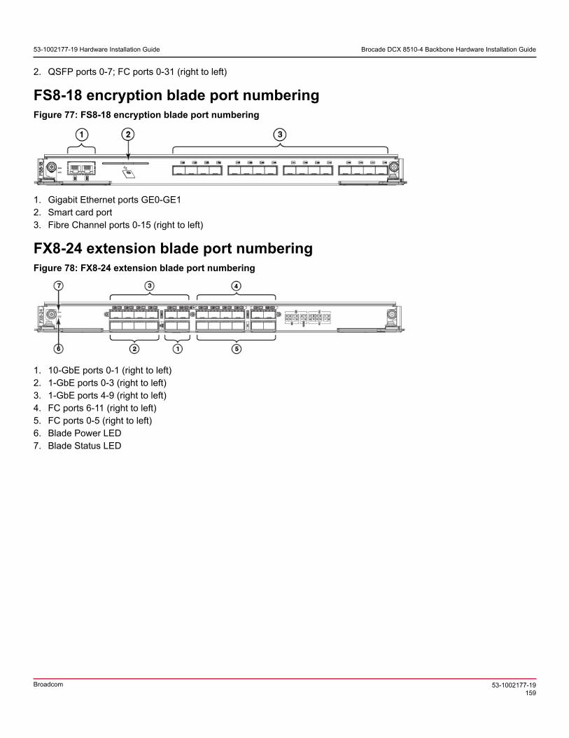
53-1002177-19 Hardware Installation Guide Brocade DCX 8510-4 Backbone Hardware Installation Guide
2. QSFP ports 0-7; FC ports 0-31 (right to left)
FS8-18 encryption blade port numberingFigure 77: FS8-18 encryption blade port numbering
1. Gigabit Ethernet ports GE0-GE12. Smart card port3. Fibre Channel ports 0-15 (right to left)
FX8-24 extension blade port numberingFigure 78: FX8-24 extension blade port numbering
1. 10-GbE ports 0-1 (right to left)2. 1-GbE ports 0-3 (right to left)3. 1-GbE ports 4-9 (right to left)4. FC ports 6-11 (right to left)5. FC ports 0-5 (right to left)6. Blade Power LED7. Blade Status LED
53-1002177-19159
Broadcom

53-1002177-19 Hardware Installation Guide Brocade DCX 8510-4 Backbone Hardware Installation Guide
Diagnostics and Troubleshooting
IntroductionFor information about troubleshooting the entire fabric, refer to the Fabric OS Troubleshooting and Diagnostics Guide.
The device includes a number of diagnostic aids to assist with troubleshooting, including LEDs on the hardware,commands that display current status, diagnostic tests for hardware and software, and error messages. In addition, anumber of managing and monitoring features are available, such as Fabric Manager, Web Tools, Fabric Watch, andAdvanced Performance Monitoring.
If the device does not operate as expected, the following steps can be taken to diagnose the problem:
• Check the LEDs on system components on the front and back of the device and refer to the LED tables in the "SystemMonitoring" section for interpretation and recommended actions.
• Review the results of the last POST run by the device and refer to the "Interpreting POST and boot results" section formore information.
• Review the error logs. Refer to the Fabric OS Troubleshooting and Diagnostics Guide for more information.– Review RASlog entries.– Use the sensorShow command to determine the status of the hardware components.– Refer to "Diagnostics" in the "Diagnostics and Troubleshooting" section to run diagnostic tests.– Reboot the device or power entire chassis off and then on using procedures in Providing power to the device and
Powering off the chassis.
If the problem is still unresolved after these steps, contact your support provider.
Obtaining chassis and component statusThe CLI commands in the following table provide status and environmental information about the chassis and itscomponents. These commands provide information only, and they do not interrupt traffic flow. For more information aboutthese commands, refer to the Brocade Fabric OS Command Reference.
Table 26: Environmental status and maintenance commands
Command Information displayed
Temperature readings for the port bladesTemperature readings for the CP bladesStatus and RPM of all operational fans
sensorShow
Status of all operational power suppliestempShow Temperature readings for the port bladesTemperature readings for the CP bladespsShow Status of all operational power suppliesfanShow Status and RPM of all operational fanschassisShow Serial number, time awake, and additional information about each
componentslotShow Slot occupancyerrShowerrDump System error log. Refer to the Brocade Fabric OS Message
Reference for more information on the messages in this log.
53-1002177-19160
Broadcom

53-1002177-19 Hardware Installation Guide Brocade DCX 8510-4 Backbone Hardware Installation Guide
Interpreting POST and boot resultsThe device performs Power-On Self-Test (POST) by default each time the chassis is powered on, rebooted, or reset.The device can be rebooted using the reboot (to reboot each CP individually) or fastBoot commands. The fastBootcommand reboots the switches without running POST. If the active CP blade is rebooted, it fails over to the standby CPblade.
POSTThe device automatically performs POST each time it is powered on or reset.
To verify that POST has completed without error, do the following:
• Verify that all LEDs return to a normal state after POST completes.If one or more LEDs do not return to a normal state, and this is not due to the device being set to beacon, refer to therelevant LED table to identify and correct the problem. For port blades, and CP and core switch blades, the slotShowcommand can be used to check the status of the slots. For information about turning beaconing on or off, refer to theBrocade Fabric OS Administration Guide.
• Verify that the switch prompt displays when POST completes.If it does not display, POST was not successfully completed. Contact the device supplier for support.
• Review the system error log using the errShow or errDump commands.Any errors detected during POST are written to the system log, which is accessible through the errShow command.For information about error messages, refer to the Brocade Fabric OS Message Reference.
POST includes the following steps:
1. Preliminary POST diagnostics are run.
2. Operating system is initialized.
3. Hardware is initialized.
4. Diagnostic tests are run on several functions, including circuitry, port functionality, ability to send and receive frames,all aspects of memory, parity, statistics counters, and serialization.
BootIn addition to POST, boot includes the following steps after POST is complete:
1. Universal port configuration is performed.
2. Links are initialized.
3. Fabric is analyzed. If any ports are connected to other switches, the device participates in a fabric configuration.
4. The device obtains a domain ID and assigns port addresses.
5. Unicast routing tables are constructed.
6. Normal port operation is enabled.
DiagnosticsDiagnostic tests are automatically run during POST to check the status of the device. Any error messages generatedduring POST are sent to the error logs and to the serial console, if connected.
Diagnostic tests can also be run manually to test and troubleshoot the hardware and the firmware, including internalconnections and circuitry, transceivers, and port cables. However, diagnostic tests are generally intended for use bysupport personnel.
53-1002177-19161
Broadcom

53-1002177-19 Hardware Installation Guide Brocade DCX 8510-4 Backbone Hardware Installation Guide
NOTEError messages do not necessarily indicate that the device requires maintenance.
Each diagnostic test can be implemented by entering the related command through a Telnet or serial session. For a list ofdiagnostic tests and commands, refer to the Brocade Fabric OS Administration Guide.
All diagnostic tests are run at all supported link speeds. They might temporarily lock the transmit and receive speeds toa specific speed. Some diagnostic tests require interconnecting the ports to each other or using loopback plugs. If portsare interconnected, the media (cables and transceivers) at each end of the connection must be of the same type. Forexample, short wavelength media must be connected to short wavelength media, and likewise with long wavelengthmedia and copper media.
For more information about diagnostic tests and how to run them, refer to the Brocade Fabric OS Administration Guideand the Brocade Fabric OS Command Reference. For information about system error messages (errShow or errDump ),refer to the Fabric OS Troubleshooting and Diagnostics Guide.
TroubleshootingThe following table provides a list of issues, possible causes, and recommended actions.
Table 27: Troubleshooting the device
Issue Possible cause Recommended action
Entire chassis powers off automatically. Power supplies are inadequate to supportthe installed components.
Add an additional power supply.
One or both power cables may not beconnected to a live source.
Ensure that both power cables areconnected to live outlets.
Several or all components are notoperating.
One or both AC power switches might beoff.
Ensure that both AC power switches are on(AC switches light up green when on).
Serial cable is not connected correctly. Ensure that the cable is firmly connected toworkstation computer and to the device.
Terminal emulator application parametersare not set correctly.
Ensure that the terminal emulatorapplication is configured as follows: 9600bits per second, 8 databits, no parity, 1 stopbit, no flow control.
Serial port might be incompatible (onlyRS-232 is supported).
Ensure that the device is connected to anRS-232 port. RS-423 serial ports mightexperience difficulties due to corner-caseincompatibilities of the standards.
Serial connection is faulty or serial port logshave incorrect or missing information.
Pins on the serial cable or serial port mightbe damaged.
Remove the cable and inspect the pinson the cable and in the serial port. Do notreinstall if the pins on either componenthave any visible damage, as this coulddamage the pins on the other component.Replace the components as required.
CP Ethernet link speed is different thanexpected or a link cannot be established.
There might be a conflict with the CPEthernet link speed negotiation set up bythe network.
Specify the CP Ethernet link speed bytyping the ifModeSet command.For more information about Ethernetconnectivity to the device, refer to the LANguidelines provided through the MyBrocadewebsite.
Configuration data is inaccurate or cannotbe accessed.
Chassis was powered off/on while a WWNcard was uninstalled or failed.
Install an operational WWN card and powerthe system off/on again.
53-1002177-19162
Broadcom

53-1002177-19 Hardware Installation Guide Brocade DCX 8510-4 Backbone Hardware Installation Guide
Issue Possible cause Recommended action
The device was rebooted while an WWNcard was uninstalled or failed.
Initial setup results in IP address/Domain IDconflict.
The device was connected to the fabricbefore being configured.
Refer to the Brocade Fabric OSAdministration Guide for configurationinformation.
The device might be booting or runningPOST.
Verify that boot and POST are complete.The device requires a minimum of 3minutes, usually, after power-on tocomplete POST.
Beaconing might be on for the entire deviceor for individual components.
Determine whether beaconing is on bytyping the switchShow command anddetermine whether switch beaconing orblade beaconing are on.
Individual components might have failed. Refer to the LED tables in the "SystemMonitoring" section for interpretation andrecommended actions.
LEDs on one or more components arechanging rapidly or do not indicate ahealthy state.
Pins on the components might bedamaged.
Remove the component from the chassisand inspect the pins on the component andinside the chassis. Do not reinstall if pinson either component are damaged, as thiscould damage pins on other components.Replace the parts as required.
Component might not be seated correctly. Ensure that the device has power andthe component is firmly seated. If theproblem continues, enter the sensorShowcommand to determine the componentstatus. If the component is a CP blade orport blade, enter the slotShow commandto determine the status.
None of the LEDs on a component are on.
Component might have failed. Replace the component as necessary.There is excessive serial port activity. Ensure that the serial port activity remains
below specified amount.CP blade is attached to an Ethernet withhigh traffic loads.
Ensure that the Ethernet traffic remainsbelow specified amount
CP blades are failing over frequently.
Chassis is overheated. Enter the tempshow and sensorShowcommands to check internal temperature.If components are overheating, shut downport blades as necessary to return thetemperature to operating range. Also trymoving the blades in the chassis becauseit is possible that airflow might not beadequate to cool everything in certainconfigurations.
One or more port blades have either shutdown or failed POST as indicated by theerror log.
Blades might be overheated. Enter the sensorShow command tocheck the internal temperature readings.If components are overheating, shut downport blades as necessary to return thetemperature readings to the operatingranges. Also try moving the blades in thechassis because it is possible that airflowmight not be adequate to cool everything incertain configurations.
53-1002177-19163
Broadcom

53-1002177-19 Hardware Installation Guide Brocade DCX 8510-4 Backbone Hardware Installation Guide
Issue Possible cause Recommended action
Blades might be faulty. Enter the slotShow command todetermine status. For more information,enter the diagDisablePost command;then, use the slotPowerOff [slotnumber] and slotPowerOn [slotnumber[ command. Resolve the sourceof the problem or replace the blade asrequired.
Pins on the blade or the backplane mightbe damaged.
Remove the blade from the chassis andinspect the pins on the blade and on thebackplane inside the slot. Do not reinstall ifthe pins on either component are damaged,as this could damage pins on othercomponents. Replace the components asrequired.
Component may not have power or may notbe firmly seated.
Ensure that the component is receivingpower (power LED should be on) and thecomponent is firmly seated.
Pins on the component or the backplanemight be damaged.
Remove the component from the chassisand inspect the pins on the blade andinside the chassis. Do not reinstall if thepins on either component are damaged,as this could damage pins on othercomponents. Replace parts as required.
An individual component is not operating as expected.
The component might have failed. Enter the tempshow and sensorShowcommand to determine the componentstatus. If the component is a CP blade orport blade, enter the slotShow commandto determine the status. Replace thecomponent as necessary.
53-1002177-19164
Broadcom

53-1002177-19 Hardware Installation Guide Brocade DCX 8510-4 Backbone Hardware Installation Guide
Regulatory Statements
BSMI Statement (Taiwan)
Warning:
This is Class A product. In a domestic environment, this product may cause radio interference, in which case the user maybe required to take adequate measures.
Canadian RequirementsThis Class A digital apparatus meets all requirements of the Canadian Interference-Causing Equipment Regulations,ICES-003 Class A.
Cet appareil numérique de la classe A est conforme à la norme NMB-003 du Canada.
CE StatementATTENTIONThis is Class A product. In a domestic environment, this product may cause radio interference, in which case theuser may be required to take adequate measures.
The standards compliance label on this device contains the CE mark, which indicates that this system conforms to theprovisions of the following European Council directives, laws, and standards:
• Electromagnetic Compatibility (EMC) Directive 2014/30/EU• Low Voltage Directive (LVD) 2014/35/EU• EN 55032/EN 55024 (European Immunity Requirements)
– EN61000-3-2/JEIDA (European and Japanese Harmonics Spec)– EN61000-3-3
53-1002177-19165
Broadcom

53-1002177-19 Hardware Installation Guide Brocade DCX 8510-4 Backbone Hardware Installation Guide
China ROHS
FCC Warning (U.S. Only)This equipment has been tested and complies with the limits for a Class A computing device pursuant to Part 15 of theFCC rules. These limits are designed to provide reasonable protection against harmful interference when the equipment isoperated in a commercial environment.
This equipment generates, uses, and can radiate radio frequency energy, and if not installed and used in accordancewith the instruction manual, might cause harmful interference to radio communications. Operation of this equipment in aresidential area is likely to cause harmful interference, in which case the user will be required to correct the interference atthe user’s own expense.
Germany statementMachine noise information regulation - 3. GPSGV, the highest sound pressure level value is 79.0 dB(A) in accordancewith EN ISO 7779.
Maschinenlärminformations-Verordnung - 3. GPSGV, der höchste Schalldruckpegel beträgt 79.0 dB(A) gemäss EN ISO7779.
KCC Statement (Republic of Korea)
Class A device (Broadcasting Communication Device for Office Use): This device obtained EMC registration for office use(Class A), and may be used in places other than home. Sellers and/or users need to take note of this.
53-1002177-19166
Broadcom

53-1002177-19 Hardware Installation Guide Brocade DCX 8510-4 Backbone Hardware Installation Guide
VCCI Statement
This is a Class A product based on the standard of the Voluntary Control Council for Interference by InformationTechnology Equipment (VCCI). If this equipment is used in a domestic environment, radio disturbance might arise. Whensuch trouble occurs, the user might be required to take corrective actions.
53-1002177-19167
Broadcom

53-1002177-19 Hardware Installation Guide Brocade DCX 8510-4 Backbone Hardware Installation Guide
Caution and Danger Notices
CautionsA Caution statement alerts you to situations that can be potentially hazardous to you or cause damage to hardware,firmware, software, or data.
Ein Vorsichthinweis warnt Sie vor potenziellen Personengefahren oder Beschädigung der Hardware, Firmware, Softwareoder auch vor einem möglichen Datenverlust
Un message de mise en garde vous alerte sur des situations pouvant présenter un risque potentiel de dommagescorporels ou de dommages matériels, logiciels ou de perte de données.
Un mensaje de precaución le alerta de situaciones que pueden resultar peligrosas para usted o causar daños en elhardware, el firmware, el software o los datos.
Electrical CautionsCAUTIONUse a separate branch circuit for each power cord, which provides redundancy in case one of the circuits fails.
VORSICHT Es empfiehlt sich die Installation eines separaten Stromkreiszweiges für jede Elektroschnur als Redundanz imFall des Ausfalls eines Stromkreises.
MISE EN GARDE Utilisez un circuit de dérivation différent pour chaque cordon d’alimentation ainsi, il y aura un circuit redondanten cas de panne d’un des circuits.
PRECAUCIÓN Use un circuito derivado separado para cada cordón de alimentación, con lo que se proporcionará redundanciaen caso de que uno de los circuitos falle.
CAUTIONBefore plugging a cable into any port, be sure to discharge the voltage stored on the cable by touching theelectrical contacts to ground surface.
VORSICHT Bevor Sie ein Kabel in einen Anschluss einstecken, entladen Sie jegliche im Kabel vorhandene elektrischeSpannung, indem Sie mit den elektrischen Kontakten eine geerdete Oberfläche berühren.
MISE EN GARDE Avant de brancher un câble à un port, assurez-vous de décharger la tension du câble en reliant les contactsélectriques à la terre.
PRECAUCIÓN Antes de conectar un cable en cualquier puerto, asegúrese de descargar la tensión acumulada en el cabletocando la superficie de conexión a tierra con los contactos eléctricos.
CAUTIONStatic electricity can damage the chassis and other electronic devices. To avoid damage, keep static-sensitivedevices in their static-protective packages until you are ready to install them.
VORSICHT Statische Elektrizität kann das System und andere elektronische Geräte beschädigen. Um Schäden zuvermeiden, entnehmen Sie elektrostatisch empfindliche Geräte erst aus deren antistatischer Schutzhülle, wennSie bereit für den Einbau sind.
MISE EN GARDE L'électricité statique peut endommager le châssis et les autres appareils électroniques. Pour éviter toutdommage, conservez les appareils sensibles à l'électricité statique dans leur emballage protecteur tant qu'ilsn'ont pas été installés.
53-1002177-19168
Broadcom

53-1002177-19 Hardware Installation Guide Brocade DCX 8510-4 Backbone Hardware Installation Guide
PRECAUCIÓN La electricidad estática puede dañar el chasis y otros dispositivos electrónicos. A fin de impedir que seproduzcan daños, conserve los dispositivos susceptibles de dañarse con la electricidad estática dentro de lospaquetes protectores hasta que esté listo para instalarlos.
CAUTIONIf you do not install a module or a power supply in a slot, you must keep the slot filler panel in place. If you runthe chassis with an uncovered slot, the system will overheat.
VORSICHT Falls kein Modul oder Netzteil im Steckplatz installiert wird, muss die Steckplatztafel angebracht werden. Wennein Steckplatz nicht abgedeckt wird, läuft das System heiß.
MISE EN GARDE Si vous n’installez pas de module ou de bloc d'alimentation dans un slot, vous devez laisser le panneau du sloten place. Si vous faites fonctionner le châssis avec un slot découvert, le système surchauffera.
PRECAUCIÓN Si no instala un módulo o un fuente de alimentación en la ranura, deberá mantener el panel de ranuras en sulugar. Si pone en funcionamiento el chasis con una ranura descubierta, el sistema sufrirá sobrecalentamiento.
Danger NoticesA Danger statement indicates conditions or situations that can be potentially lethal or extremely hazardous to you. Safetylabels are also attached directly to products to warn of these conditions or situations.
Ein Gefahrenhinweis warnt vor Bedingungen oder Situationen die tödlich sein können oder Sie extrem gefährden können.Sicherheitsetiketten sind direkt auf den jeweiligen Produkten angebracht um vor diesen Bedingungen und Situationen zuwarnen.
Un énoncé de danger indique des conditions ou des situations potentiellement mortelles ou extrêmement dangereuses.Des étiquettes de sécurité sont posées directement sur le produit et vous avertissent de ces conditions ou situations.
Una advertencia de peligro indica condiciones o situaciones que pueden resultar potencialmente letales oextremadamente peligrosas. También habrá etiquetas de seguridad pegadas directamente sobre los productos paraadvertir de estas condiciones o situaciones.
Electrical DangersDANGERMake sure that the power source circuits are properly grounded, and then use the power cord supplied with thedevice to connect it to the power source.
GEFAHR Stellen Sie sicher, dass die Stromkreise ordnungsgemäß geerdet sind. Benutzen Sie dann das mit dem Gerätgelieferte Stromkabel, um es an die Srromquelle anzuschließen.
DANGER Vérifiez que les circuits de sources d'alimentation sont bien mis à la terre, puis utilisez lecordon d'alimentationfourni avec le dispositif pour le connecter à la source d'alimentation.
PELIGRO Verifique que circuitos de la fuente de corriente están conectados a tierra correctamente; luego use el cordónde potencia suministrado con el instrumento para conectarlo a la fuente de corriente
DANGERFor safety reasons, the ESD wrist strap should contain a series 1 megaohm resistor.
GEFAHR Aus Sicherheitsgründen sollte ein EGB-Armband zum Schutz von elektronischen gefährdeten Bauelementenmit einem 1 Megaohm-Reihenwiderstand ausgestattet sein.
DANGER Pour des raisons de sécurité, la dragonne ESD doit contenir une résistance de série 1 méga ohm.PELIGRO Por razones de seguridad, la correa de muñeca ESD deberá contener un resistor en serie de 1 mega ohmio.
53-1002177-19169
Broadcom

53-1002177-19 Hardware Installation Guide Brocade DCX 8510-4 Backbone Hardware Installation Guide
DANGERRemove both power cords before servicing.
GEFAHR Trennen Sie beide Netzkabel, bevor Sie Wartungsarbeiten durchführen.DANGER Retirez les deux cordons d'alimentation avant toute maintenance.PELIGRO Desconecte ambos cables de alimentación antes de realizar reparaciones.
DANGERDisconnect the power cord from all power sources to completely remove power from the device.
GEFAHR Ziehen Sie das Stromkabel aus allen Stromquellen, um sicherzustellen, dass dem Gerät kein Strom zugeführtwird.
DANGER Débranchez le cordon d'alimentation de toutes les sources d'alimentation pour couper complètementl'alimentation du dispositif.
PELIGRO Para desconectar completamente la corriente del instrumento, desconecte el cordón de corriente de todas lasfuentes de corriente.
DANGERIf the installation requires a different power cord than the one supplied with the device, make sure you use apower cord displaying the mark of the safety agency that defines the regulations for power cords in your country.The mark is your assurance that the power cord can be used safely with the device.
GEFAHR Falls für die Installation ein anderes Stromkabel erforderlich ist (wenn das mit dem Gerät gelieferte Kabel nichtpasst), müssen Sie sicherstellen, dass Sie ein Stromkabel mit dem Siegel einer Sicherheitsbehörde verwenden,die für die Zertifizierung von Stromkabeln in Ihrem Land zuständig ist. Das Siegel ist Ihre Garantie, dass dasStromkabel sicher mit Ihrem Gerät verwendet werden kann.
DANGER Si l'installation nécessite un cordon d'alimentation autre que celui fourni avec le dispositif, assurez-vousd'utiliser un cordon d'alimentation portant la marque de l'organisation responsable de la sécurité qui définit lesnormes et régulations pour les cordons d'alimentation dans votre pays. Cette marque vous assure que vouspouvez utiliser le cordon d'alimentation avec le dispositif en toute sécurité.
PELIGRO Si la instalación requiere un cordón de corriente distinto al que se ha suministrado con el instrumento,verifique que usa un cordón de corriente que venga con la marca de la agencia de seguridad que defina lasregulaciones para cordones de corriente en su país. Esta marca será su garantía de que el cordón de corrientepuede ser utilizado con seguridad con el instrumento.
Dangers Related to Equipment WeightDANGERUse safe lifting practices when moving the product.
GEFAHR Beim Bewegen des Produktes ist auf eine sichere Hubtechnik zu achten.DANGER Utiliser des techniques de levage sûres pour déplacer le produit.PELIGRO Tenga mucho cuidado al levantar el producto para moverlo
53-1002177-19170
Broadcom

53-1002177-19 Hardware Installation Guide Brocade DCX 8510-4 Backbone Hardware Installation Guide
DANGERA fully populated chassis (four FC16-64 port cards, 256 ports) weighs approximately 69.5 kg (153 lbs) andrequires a hydraulic or assisted lift to install it.
GEFAHR Ein vollständig bestücktes Gerät (vier FC16-64-Port-Karten, 256 Ports) wiegt etwa 69 kg und erfordert zurInstallation eine hydraulische oder Servo-Hebevorrichtung.
DANGER Un commutateur complet (quatre cartes de port FC16-64, 256 ports) pèse environ 69.5 kg et requiert undispositif de levage hydraulique ou électrique pour l'installation.
PELIGRO Un chasis con la configuración completa (cuatro tarjetas para puertos FC16-64, 256 puertos) pesaaproximadamente 69.5 kg (153 libras) y requiere un elevador hidráulico o asistido para realizar su instalación.
Laser DangersDANGERUse only optical transceivers that are qualified by Broadcom and comply with the FDA Class 1 radiationperformance requirements defined in 21 CFR Subchapter I, and with IEC 60825 and EN60825. Optical productsthat do not comply with these standards might emit light that is hazardous to the eyes.
GEFAHR Verwenden Sie nur optische Transceiver, die von Broadcom zugelassen sind und die die Anforderungengemäß FDA Class 1 Radiation Performance Standards in 21 CFR, Unterkapitel I, sowie IEC 60825 undEN60825 erfüllen. Optische Produkte, die diese Normen nicht erfüllen, können Strahlen aussenden, die für dasmenschliche Auge gefährlich sind.
DANGER Utilisez uniquement des émetteurs-récepteurs optiques certifiés par Broadcom et conformes aux exigencessur la puissance de rayonnement de catégorie 1 de la FDA définies au sous-chapitre 21 CFR I et à les normesIEC 60825 et EN60825. Les produits optiques non-conformes à ces normes sont susceptibles d’émettre unelumière dangereuse pour les yeux.
PELIGRO Utilice sólo transceptores ópticos aprobados por Broadcom y que cumplan con las normas IEC 60825 yEN60825, y con los estándares de rendimiento Clase 1 de FDA definidos en el subcapítulo I de 21 CFR. Losproductos ópticos que no cumplan con estos estándares pueden emitir luz dañina para los ojos.
Danger-laser Shared
Laser DangersDANGERAll fiber-optic interfaces use Class 1 lasers.
GEFAHR Alle Glasfaser-Schnittstellen verwenden Laser der Klasse 1.DANGER Toutes les interfaces en fibre optique utilisent des lasers de classe 1.PELIGRO Todas las interfaces de fibra óptica utilizan láser de clase 1.
DANGERLaser Radiation. Do Not View Directly with Optical Instruments. Class 1M Laser Products.
GEFAHR Laserstrahlung! Schauen Sie nicht direkt mit optischen Instrumenten in den Laserstrahl herein. Klasse 1MLaserprodukte.
DANGER Rayonnement de laser. Ne regardez pas directement avec des instruments optiques. Produits de laser declasse 1M.
PELIGRO Radiacion de Laser. No vea directamente con Instrumentos Opticos. Clase 1M de Productos de Laser.警告 レーザ放射 光学器具で直接ビームを見ないこと クラス1 M レーザ製品
53-1002177-19171
Broadcom

53-1002177-19 Hardware Installation Guide Brocade DCX 8510-4 Backbone Hardware Installation Guide
DANGERUse only optical transceivers that are qualified by Broadcom and comply with the FDA Class 1 radiationperformance requirements defined in 21 CFR Subchapter I, and with IEC 60825 and EN60825. Optical productsthat do not comply with these standards might emit light that is hazardous to the eyes.
GEFAHR Verwenden Sie nur optische Transceiver, die von Broadcom zugelassen sind und die die Anforderungengemäß FDA Class 1 Radiation Performance Standards in 21 CFR, Unterkapitel I, sowie IEC 60825 undEN60825 erfüllen. Optische Produkte, die diese Normen nicht erfüllen, können Strahlen aussenden, die für dasmenschliche Auge gefährlich sind.
DANGER Utilisez uniquement des émetteurs-récepteurs optiques certifiés par Broadcom et conformes aux exigencessur la puissance de rayonnement de catégorie 1 de la FDA définies au sous-chapitre 21 CFR I et à les normesIEC 60825 et EN60825. Les produits optiques non-conformes à ces normes sont susceptibles d’émettre unelumière dangereuse pour les yeux.
PELIGRO Utilice sólo transceptores ópticos aprobados por Broadcom y que cumplan con las normas IEC 60825 yEN60825, y con los estándares de rendimiento Clase 1 de FDA definidos en el subcapítulo I de 21 CFR. Losproductos ópticos que no cumplan con estos estándares pueden emitir luz dañina para los ojos.
53-1002177-19172
Broadcom

53-1002177-19 Hardware Installation Guide Brocade DCX 8510-4 Backbone Hardware Installation Guide
Revision History
53-1002177-19; 2 June 2020
The following changes have been made:
• Removed the "Brocade DCX 8510 Technical Specifications" section from this guide. The technical specifications are provided in a separate guide.
• Modified the following sections in Chassis removal and replacement:– Removed the "Verifying the PID mode" section from the "Initial setup and configuration" section as it is no longer
necessary for configuration.– Recording critical device information – Revised the introduction to using critical information checklist, removed the
note to run the supportShow command, removed the -sw option from the step to enter the ipAddrShow command, and added more information to the step to enter the supportShow command.
– Reconnecting the system to the network and fabric – Revised Step 1 to include references to sections in "Initial configuration" for connecting a serial cable, establishing a serial connection, configuring IP addresses, and establishing an Ethernet connection to the device.
– Verifying correct operation of system – Moved this section to after Reconnecting the system to the network and fabric.
– Verifying correct configuration of the fabric – Added a step to modify the SCC policy for a fabric, if one exists, to add the WWN of the new chassis.
• Corrected the torque requirements in the following sections of "Installing the 8U Chassis Airflow Diversion or Port Side Exhaust Kit for Four-Post Racks (XBR-DCX4S-0121 and XBR-DCX4S-0130)":– "Installing device in 18-24 inch rack (XBR0DCX4S-0130)"– "Installing device in 27-31 inch rack (XBR-DCX4S-0121)"
53-1002177-19173
Broadcom