Broadband Wireless Technologies and Businessnifrasmail.weebly.com/uploads/2/1/6/7/2167487/...3G to...
27
Broadband Wireless Technologies, Standards and Service Riaz Esmailzadeh Carnegie Mellon University [email protected] 27 July 2007 © Riaz Esmailzadeh 2 Overview Broadband Wireless Technologies Transmission Rates Technology Differences Throughput Calculations Standards 3G to 4G CDMA – Based OFDMA – Based Enhancing Technologies Services Revenue Flow Value Chain Expected Growth
Transcript of Broadband Wireless Technologies and Businessnifrasmail.weebly.com/uploads/2/1/6/7/2167487/...3G to...

Broadband Wireless
Technologies, Standards and Service
Riaz EsmailzadehCarnegie Mellon [email protected]
27 July 2007 © Riaz Esmailzadeh 2
Overview
Broadband Wireless Technologies
Transmission Rates Technology DifferencesThroughput Calculations
Standards 3G to 4G
CDMA – BasedOFDMA – Based Enhancing Technologies
Services
Revenue FlowValue ChainExpected Growth
27 July 2007 © Riaz Esmailzadeh 3
Broadband Wireless Technologies
Broadband Wireless Technologies
Transmission Rates Technology DifferencesThroughput Calculations
3G to 4G Standards
CDMA – BasedOFDMA – Based Enhancing Technologies
Services
Revenue FlowValue ChainExpected Growth
27 July 2007 © Riaz Esmailzadeh 4
Edholm’s Law
Ex-CTO of Nortel, projected several years ago that with the presentrate of growth in both fixed and wireless transmission rates, in a few years the transmission rates will be comparable.It would make more sense to roll-out a wireless network that a fixed network…
Source: IEEE Spectrum July 2004

27 July 2007 © Riaz Esmailzadeh 5
Downlink Transmission Rate: 5 Giga-bit/sec
Japanese operator DoCoMo announced field test results in FebruarySystem parameters:
Multiplexing method: Variable Spreading Factor – Orthogonal Frequency Division Multiple Access (VSF-OFDMA) Bandwidth: 100 MHzModulation: (256 QAM)12 x 12 MIMO antennasSingle cell
27 July 2007 © Riaz Esmailzadeh 6
There Are Challenges…
Propagation lossFrom Hata-Okumura model
Path loss increases as a power of 2.6 or (f1/f2)2.6
For f1=2 GHz and f2=5 GHz, the signal loss is almost 10 times higher at 5 GHz than 2 GHz
Required transmit power is a factor of transmission rateA 100 Kbps transmission requires 100 times more power than a 1 kbps
For a 4G vs. 3G system comparison:10 times signal loss10 times higher required transmission power due to higher bit rates100 times more required peak transmission power
Available bandwidthA chunk of 100 MHz neededGo to the 5 GHz band?
Extra path loss of 10 dB compared with the 2 GHz band
However, we have come a long way. 10-3
0 4 8 12 16 20 24
Eb/N0
BER
Fading channel
Static channel
10-2
10-1

27 July 2007 © Riaz Esmailzadeh 7
Key Requirements for 4G
High data rate, low latency, packet-optimized radio access100 Mbps peak DL rate in 20 MHz allocation50 Mbps peak UL rate in 20 MHz allocation
Spectrum flexibilityScalable bandwidths [1.25, 2.5, 5, 10, 15, 20MHz]Support for paired and unpaired spectrum assignments
Support for high speed mobility (up to 350 km/h)
Flat backbone architecture (all IP)
27 July 2007 © Riaz Esmailzadeh 8
Which Technologies
Two paths have emerged:Evolution of CDMA – based system (3GPP)Evolution of OFDMA – based systems (IEEE)
What is the difference?Philosophical really!
How is the wireless channel equalised(And how multi-user interference is dealt with).
How to operate in very wide-band channels

27 July 2007 © Riaz Esmailzadeh 9
Pos
itio
n (c
m)
Frequency (MHz)
-20
-10
0
10
Ch
an
nel g
ain
(d
B)
20102000 20050
50
40
30
20
10
Fading in Two Domains
Wireless communications system performance is degraded due to signal fading in two domains: frequency and time.Wireless transmission technologies are designed to compensate for these conditions Or Equalize the channel
*Source: Adachi, et al.
27 July 2007 © Riaz Esmailzadeh 10
Shannon Theorem
In mobile communications, which re-use frequency resources, the amount of interference from other users must be taken into account
Shannon Theorem on capacity can be approximated to include the effect of interference, I
Throughput here is calculated as a function of SINR, or SIR
The efficiency of each technologycan be evaluatedbased on this theorem
0
1
2
3
4
5
6
7
8
9
-10 -5 0 5 10 15 20 25S/(N+I) (dB)
No
rmalise
dC
ap
aci
ty (
bp
s/H
z)
Shannonlimit
⎟⎠⎞
⎜⎝⎛
++≈
IN
SBC 1log2

27 July 2007 © Riaz Esmailzadeh 11
How to Equalise
For Time and Frequency domains fading:CDMA systems equalise through
Diversity combining (rake, multiple antennas)Power control
OFDM systems equalise throughNarrow-band sub-carrier with flat fadingPower control
The other equalisation problemMulti-user interference
27 July 2007 © Riaz Esmailzadeh 12
Sources of Interference
In the uplink:All active mobile in the system transmit signals that are interference to the desired user signal
In the downlinkAll signals from other active base stations, and signals intended for other users within the same cell area are interference

27 July 2007 © Riaz Esmailzadeh 13
WCDMA (and HSDA)
The two systems differ in the way they treat interferenceCDMA systems use frequency re-use factor of oneThe sources of interference come from both within and without the cell
How these interference are minimised contributes to the increase of WCDMA average throughput
The system may be equalised through joint detection techniques (interference mitigations, both inter- and intra-cell)
32
1
27 July 2007 © Riaz Esmailzadeh 14
WiMAX
OFDMA-based systems use a TDMA system per sub-carrier, and transmits to one user at a timeHowever, inter-cell interference remains
Therefore they need to have a frequency re-use factor of more than one as the interference from neighbouring cell can be destructive
Adaptive array antenna systems, as well as adaptive frequency re-sue factors are used to reduce interference and increase the throughput efficiency
1

27 July 2007 © Riaz Esmailzadeh 15
Peak throughputAn example for a WCDMA system is calculated below. It should be noted that peak throughput figures of up to 14 Mbps have been reported. These require higher coding rates and better information efficiency than listed in this example.
1Spreading factor (chip per symbol)
4Data bits per symbol (16 QAM)
95%Information bits / transmitted bits
10.944 MbpsPeak throughput
3/4Channel coding rate
3.84 McpsChip rate
Peak Throughput
Peak throughput is calculated similarly for all technologiesIt is primarily a function of system bandwidth, and frequency re-use factor
27 July 2007 © Riaz Esmailzadeh 16
WiMAX peak throughputAn example for a 5 MHZ WiMAX system is calculated below.
12 MbpsChannel coding rate 3/4
16 Mbps64-QAM modulation: 6 bits/symbol
8680Symbol rate per sub-carrier (1 / 115.2 μsec)
115.2 μsecOFDM symbol duration
9.766 kHzSub-carrier frequency spacing
384Number of sub-carriers
2.67 MspsInformation symbol ratio (80%)
12 MbpsPeak throughput
3.3 MspsTotal symbol rate (8680x384)
5 MHz McpsSystem bandwidth
WiMAX Peak Throughput
WiMAX peak throughput is similarly calculated. It is also directly related to the system bandwidth
27 July 2007 © Riaz Esmailzadeh 17
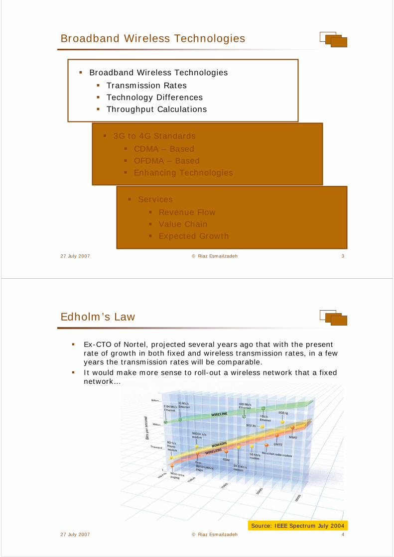
SIR = 12 dB
SIR = 9 dB
SIR = 6 dB
SIR = 0 dB
SIR = 3 dB
Average Throughput
Average throughput is calculated from SIR distribution and Shannon theoremVarious standards differ here on how they can minimize interference
27 July 2007 © Riaz Esmailzadeh 18
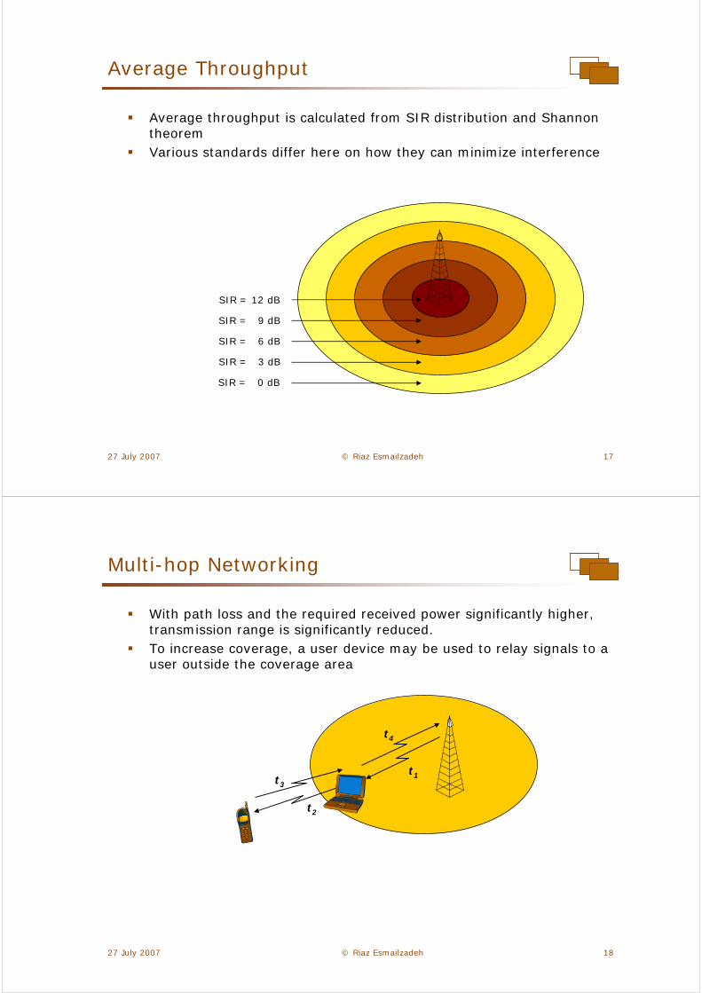
t1t3
t4
t2
Multi-hop Networking
With path loss and the required received power significantly higher, transmission range is significantly reduced. To increase coverage, a user device may be used to relay signals to a user outside the coverage area

27 July 2007 © Riaz Esmailzadeh 19
Fixed and wireless transmission rates are becoming more and more comparable
The question of which technology to choose is answered by which way multi-user interference is handled
An operator should be most interested in average throughput rates for the system, rather than a marketing-oriented peak throughput figure
To summarize …
27 July 2007 © Riaz Esmailzadeh 20
3G to 4G Standards
Broadband Wireless Technologies
Transmission Rates Technology DifferencesThroughput Calculations
3G to 4G Standards
CDMA – BasedOFDMA – Based Enhancing Technologies
Services
Revenue FlowValue ChainExpected Growth

27 July 2007 © Riaz Esmailzadeh 21
Technologies: WCDMA-HSPA
WCDMA HSPA standard is in various stages of standardization within ITU, 3GPP and ARIB
3GPP has already made 5 formal releases of the CDMA standardMost of these standards have been ratified by the ITU
June 2006Release 7
2001Release 4
Dec 2002Release 5
Dec 2004Release 6
1999Release 99
2007/2008Long Term Evolution
3GPP (Expected) Release Date
27 July 2007 © Riaz Esmailzadeh 22
A Combination of…
It is a combination of FDD, CDMA and TDMAThe Duplex mode is Time DivisionUser simultaneously connect to the system in Code division multiple access fashionUser traffic is also handled in a Frequency Division mannerThe TDD mode is a complimentary component for the new standard
FDD CDMA
TDMA
WCDMA-HSPA
Such as: GSMWCDMA
Such as: FOMAcdmaOne
Such as: GSMPDC

27 July 2007 © Riaz Esmailzadeh 23
FDD and TDD
In FDD two different frequency bands are used for downlink and uplink transmissionsIn TDD Uplink and downlink transmissionsare carried out in thesame frequency band,but at different times
While CDMA systemshave been mainly FDD, a joint TDD/FDD is being developed
While initially WiMAXsystems went the FDDway, they are now focusing on TDD
Uplink frequency band
Downlink frequency band
(FDD)
Base station
Common uplink and downlink frequency band
(TDD)
Base stationEnd-user device
End-user device
27 July 2007 © Riaz Esmailzadeh 24
Technologies: WiMAX
WiMAX specifications are being developed under IEEE 802.16e group, with several other working group contributing to the final standard: Release dates have varied: the following was presented by Intel last October: Definite Final Release 1 is expected this year...
*Source: Intel Presentation at Wireless Broadband Technical Seminar, Tokyo, Japan, 31 October 2005

27 July 2007 © Riaz Esmailzadeh 25
Uses OFDMA …
WiMAX is a combination of TDD OFDMA and TDMAThe Duplex is Time DivisionUser simultaneously connect to the system in an Orthogonal Frequency Division Multiple Access fashionUser traffic is also handled in a Time Division manner
TDD OFDMA
TDMA
WiMAX
Such as: DECTPHS
Similar to: 802.11aDAB/DVB
Such as: GSMPDC
27 July 2007 © Riaz Esmailzadeh 26
WCDMA LTE: OFDMA with Spreading
Long term evolution of CDMA standards envisages usage of OFDMAA combination of CDMA and OFDM as in the DoCoMo proposal
The OFDM part will use a scalable variable number of sub-carriersFixed sub-carrier spacing (15kHz)Spectral compatibility for deployment in existing bands
20MHz
5MHz
10MHz
15 kHz
27 July 2007 © Riaz Esmailzadeh 27
Frequency (sub-carriers)
Time(sub-frames)
code
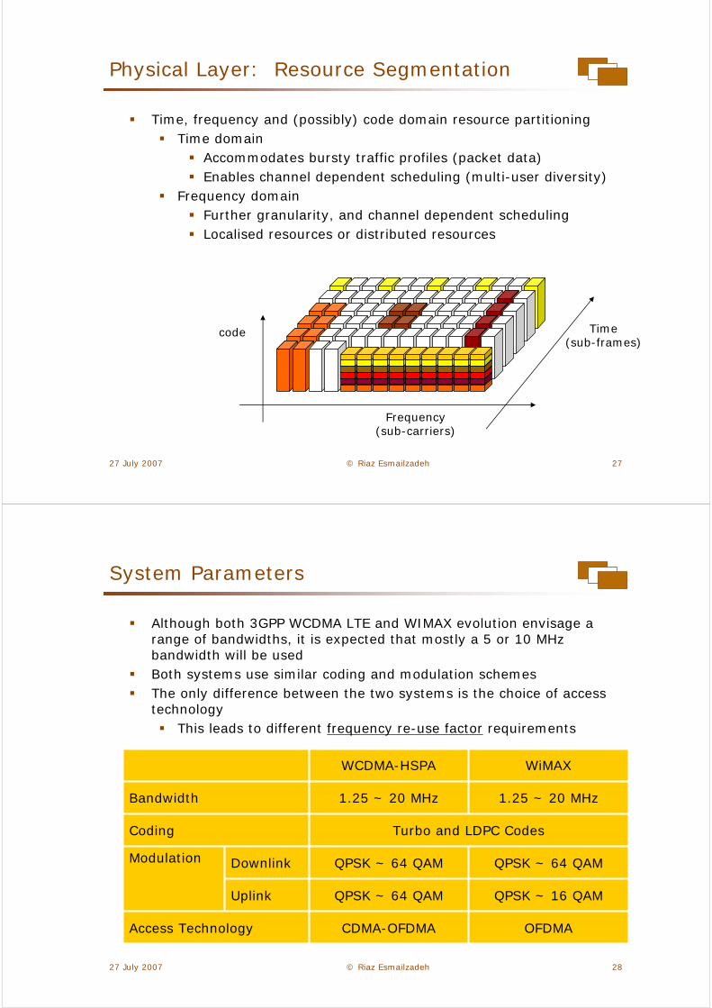
Physical Layer: Resource Segmentation
Time, frequency and (possibly) code domain resource partitioningTime domain
Accommodates bursty traffic profiles (packet data)Enables channel dependent scheduling (multi-user diversity)
Frequency domainFurther granularity, and channel dependent schedulingLocalised resources or distributed resources
27 July 2007 © Riaz Esmailzadeh 28
System Parameters
Although both 3GPP WCDMA LTE and WIMAX evolution envisage a range of bandwidths, it is expected that mostly a 5 or 10 MHz bandwidth will be usedBoth systems use similar coding and modulation schemesThe only difference between the two systems is the choice of access technology
This leads to different frequency re-use factor requirements
QPSK ~ 16 QAM
QPSK ~ 64 QAM
Uplink
Downlink QPSK ~ 64 QAM
1.25 ~ 20 MHz
OFDMA
QPSK ~ 64 QAM
Modulation
CDMA-OFDMAAccess Technology
Turbo and LDPC Codes Coding
1.25 ~ 20 MHzBandwidth
WiMAXWCDMA-HSPA

27 July 2007 © Riaz Esmailzadeh 29
Key Parameters
The following table shows the general guidelines for the LTEThese are expected within 2009-2010 release
Paired & Unpaired
1.25, 2.5, 5, 10, 15, 20
< 5 ms
192-256 kbps
1 – 2 Mbps
0.48 – 0.72 b/s/Hz
1.2 – 1.6 b/s/Hz
2.5b/s/Hz
5b/s/Hz
Net Requirement Set By Operators
Duplex Modes
Cell Edge Rate - Downlink
Cell Edge Rate - Uplink
Parameter
Channel bandwidths (MHz)
Delay one way (active state, single user, unloaded)
Spectral efficiency- Uplink
Spectral efficiency- Downlink
Uplink Peak User Throughput
Downlink Peak User Throughput
27 July 2007 © Riaz Esmailzadeh 30
Frequency Re-Use
Usually the spectrum is re-used in many different base stationsIf two base stations are sufficiently separated, they can re-use the same spectrum to communicate with their mobiles
WiMAX systems propose a partialfrequency re-use, where areas in the centre of a cell can havere-use factor of 1, and cell-edgea re-use factor of 3.
f1+f2+f3
f1
f2f3
f1+f2+f3
f1+f2+f3

27 July 2007 © Riaz Esmailzadeh 31
IMT Extension band:Europe, Japan, KoreaTDD or FDDMMDS band:USA, CanadaTDD or FDD
2.5 ~ 2.69 GHz
IMT 2000: FDDEurope, Japan, Korea, China
2.11 ~ 2.17 GHz
IMT 2000: TDDEurope, Japan, Korea, China
2.01 ~ 2.025 GHz
IMT-2000 TDDChinaMobile InternetKorea
2.3 ~ 2.4 GHz
2 G
Hz
Ban
d
1.92 ~ 1.98 GHz
Presently usedfor 1G, 2G450 MHz800 MHz bandsTDD or FDDVarious Worldwide
Sub 1 GHz
IMT-2000 FDD1.72~1.78JapanCanada?
1.7 GHz
< 2
GH
z B
an
d
Possible BroadbandWireless5.470 – 5.725 : Asia, Americas, Europe
5.7 ~ 5.8 GHz
Broadband Wireless3.3- 3.4 GHz: China, India3.4-3.6 GHz: Worldwide3.6-3.8 GHz: USA, CanadaTDD or FDD
3.3 ~ 3.8 GHz
3 &
5 G
Hz
Ban
d
IMT-2000 TDDEurope, ChinaKorea
1.9 ~ 1.92 GHz
IMT 2000: FDDEurope, Japan, Korea, China
Allocated Spectrum
Several frequency bands can be considered for future releases of 3G standards.
27 July 2007 © Riaz Esmailzadeh 32
Switching Technology
Switching technologies have now also merged:Data over wired network has long been packet switchedVoice communications over wire is now increasingly packet switched: VoIP
Similarly in wirelessData is now increasingly packet switchedVoice is also converging to packet switching: Wireless VoIP
Web
Email Circuit Switched
Voice
2G
Video
Voice
Web
Streaming
Packet Switched
MMS
Packet Switched
VideoCircuit
SwitchedVoice
Web
Streaming
MMS
3G Early Releases
3G Release 5 ~

27 July 2007 © Riaz Esmailzadeh 33
IP End-to-End
Services of the future will be packet switchedThe backbone network will operate using IPOffered services will also use IPUsing an end-to-end IP network design will reduce
Design costIntegration costOperating costLayout and expansion cost
Base station
IP Network
Server
Other Networks
27 July 2007 © Riaz Esmailzadeh 34
LTE Architecture
The backbone is based on a flat all-IP architecture
IMS ServiceNetwork
“Public” IP WAN
ISP network
Private network
PSTN
Signalling
User data
E-UTRAN
Operator Managed IP backbone
E-Node BE-Node B
E-Node B
E-Node BE-Node B
LTE GW

27 July 2007 © Riaz Esmailzadeh 35
Base station
User equipment
Antennaelements
Antennaelements
> λ/2
Using MIMO
MIMO (multiple-input multiple-output) technology is the usage of multiple antennas at both the transmitter and receiver sidesThis in effect creates parallel channels. The channel capacity can therefore be increased several times. For example the DoCoMo systems uses 12 antennas at each side
Under ideal conditions, this increases throughput 12 timesFor this to work, antenna elements must be sufficiently apart
27 July 2007 © Riaz Esmailzadeh 36
Information bits
Transmittedpacket
NACK
Buffer
Re-transmitpunctured bit
if NACK
Information bits
Paritybits
Puncturedparity bit
Hybrid ARQ (Incremental Redundancy)
When “S” term is high in Shannon Theorem, higher transmission rates may be supported. This Hybrid ARQ scheme facilitates its realisation

27 July 2007 © Riaz Esmailzadeh 37
0
50
100
150
200
250
300
350
-10 -5 0 5 10 15 20 25
Th
rou
gh
pu
t
Eb/N0
Mode 1
Mode 2
Mode 3
Mode 4
Mode 5
Mode 6
Mode 7
Adaptive Coding and Modulation
When channel conditions are good then channel coding rates and modulation rates may be increased so more information is sent through the channel.
64-QAM
16-QAM
16-QAM
16-QAM
QPSK
QPSK
QPSK
Modulation
1/32
1/24
3/43
1/21
3/47
3/46
1/35
CodingRateMode
27 July 2007 © Riaz Esmailzadeh 38
Time
Am
pli
tud
e l
evel
Po
wer
level
Average power
Peak powerTime
Time
Time
Time
()2
Peak-to-Average Power Ratio (PAPR)
Multi-carrier systems suffer from large PAPR problemThis is significant particularly in regards to power amplification as non-linearity can cause clipping

27 July 2007 © Riaz Esmailzadeh 39
Power Amplifier Efficiency
Power amplifiers have a saturation level
With PAPR, the device need to operate at well below saturation level
This leadsLess efficient operation (more battery power required, more heat generated)
Cost/Battery usage can be prohibitive for handsets.
This is the reason OFDM/Multi-carrier is not used in Uplink
Input level
Outputlevel
30%6-9 dB
44%3 dB
60%0 dB
EfficiencyInput backoff
27 July 2007 © Riaz Esmailzadeh 40
To summarize …
“3G” standards evolution (both 3GPP and IEEE – based) intend to provide
Higher transmission ratesFlexible bandwidth allocationFull IP backbone architecture
Advanced antenna MIMO, and error control coding technologies helps increase the transmission rate
However, concerns remain with the electronics design aspects, specially PAPR issues for OFDM systems

27 July 2007 © Riaz Esmailzadeh 41
Services
Broadband Wireless Technologies
Transmission Rates Technology DifferencesThroughput Calculations
3G to 4G Standards
CDMA – BasedOFDMA – Based Enhancing Technologies
Services
Revenue FlowValue ChainExpected Growth
27 July 2007 © Riaz Esmailzadeh 42
End-User device
The services that can be provided are very much a factor of the end-user device capability, core purpose, and mobility
Mobility
Mini PCLaptop PC PDA Mobile

27 July 2007 © Riaz Esmailzadeh 43
User MobileOperator
Third parties
RevenueFlow
RevenueFlow
RevenueFlow
User MobileOperator
RevenueFlow
Revenue Flow
Service models, and revenue flows are also changing as many new players are entering the value chainWith the introduction of new services in 2G and 3G, the flow of revenue has become more complexIt is expected to be more complex with (4G) broadband wireless services
27 July 2007 © Riaz Esmailzadeh 44
Non-PortalContent
Aggregationand Creators
Non-PortalApplication
Platform
PortalContent
Aggregation
ThirdParty
Billing
PortalAccess
End-userBilling
IPNetwork
Access
MobileNetwork
Access
3. Access Focused Approach
2. Portal Focused Approach
1. Mobile Specialised Services
Value Chain
A value chain, based on 3G services and applications has been developed by UMTS ForumThey classify services into three groups:
*Source: UMTS Forum

27 July 2007 © Riaz Esmailzadeh 45
CustomizedInfotainment
MultimediaMessaging
Service(MMS)
LocationBased
Services
Rich/SimpleVoice
MobileInternetAccess
MobileIntranet/ExtranetAccess
Access FocusedApproach
PortalFocused
Approach
Mobile Specialized Services
Content Connectivity(Internet)
Mobility
Information and Content(Non-Voice)
Voice
Service Classification
Using this classification, service categories are defined by UMTS Forum
*Source: UMTS Forum
27 July 2007 © Riaz Esmailzadeh 46
Required Transmission Rates
Required transmission rates vary for different servicesMoreover they are expected to be different for downlink and uplinkThese help the decision making process: what amount of total transmission rates are needed for a certain customer base.
UplinkDownlink
Simple Voice
Rich Voice
Location Based Services
Multimedia Messaging Service
Customised Infotainment
Mobile Intranet/Extranet Access
Mobile Internet Access
8 kbps ~ 16 kbps16 kbps ~ 64 kbps
8 kbps ~ 32 kbps8 kbps ~ 32 kbps
1 kbps ~ 4 kbps8 kbps ~ 16 kbps
4 kbps ~ 16 kbps4 kbps ~ 16 kbps
8 kbps ~ 16 kbps
128 kbps ~ 256 kbps
32 kbps ~ 64 kbps
64 kbps ~ 128 kbps
500 kbps ~ 1 Mbps
500 kbps ~ 1 Mbps
*Source: UMTS Forum

27 July 2007 © Riaz Esmailzadeh 47
Uplink and Downlink Asymmetry
The amount of traffic in the uplink and downlink are going to be differentTDD systems are more flexible in traffic allocation
Uplink frequency band
Downlink frequency band
(FDD)
Common uplink and downlink frequency band
(TDD)
One slot
One frame
0
500
1000
1500
2000
2500
1997 2002 2007Year
Kb
ps
DownlinkUplink
Maximum throughput for D/L and U/L per User
27 July 2007 © Riaz Esmailzadeh 48
Simple and Rich Voice
This is the traditional voice service, and voice enriched by video and other functionsWhile the revenue from simple voice service is expected to decrease, revenue from rich voice service is expected to increaseTransmission rates are moderate
Source: Esmailzadeh based on UMTS Forum data 0
20
40
60
80
100
120
2005 2006 2007 2008 2009 20100
100
200
300
400
500
600
700
Rich Voice revenue ($B)Simple Voice revenue ($B)Simple voice subscribers (M)
Year
Reven
ue (
$B
)
Su
bsc
rib
ers
(M
)

27 July 2007 © Riaz Esmailzadeh 49
Customized Infotainment
Information and entertainment services are going to be a major revenue growth for operatorsModerate transmission rates
0
10
20
30
40
50
60
70
80
90
100
2005 2006 2007 2008 2009 2010Year
Reven
ue (
$B
)
0
50
100
150
200
250
300
350
Su
bsc
rib
ers
(M
)
Customised Infotainment revenue ($B)Customised Infotainment Subscribers (M)
Source: Esmailzadeh based on UMTS Forum data
27 July 2007 © Riaz Esmailzadeh 50
Mobile Intranet/Extranet
Wireless ADSL type of services, specially for the business segment is expected to grow. High transmission rates, perhaps counting for the lion share of inforamtion transferHowever, revenues are not expected to be correspondingly high
0
10
20
30
40
50
60
70
2005 2006 2007 2008 2009 2010Year
Reven
ue (
$B
)
0
50
100
150
200
250
300
Su
bsc
rib
ers
(M
)
Intranet/Extranet revenue ($B)Intranet/Extranet subscribers (M)
Source: Esmailzadeh based on UMTS Forum data

27 July 2007 © Riaz Esmailzadeh 51
Multimedia Messaging Service
Short messaging services, enhanced by multimedia features is expected to growMMS services for business, including machine-to-machine services are expected to grow rapidly.Transmission rates are expected to be low
0
5
10
15
20
25
30
35
40
45
2005 2006 2007 2008 2009 20100
20
40
60
80
100
120
140MMS business segement revenue ($B)MMS consumer segment revenue ($B)MMS consumer segment subscribers (M)
Year
Reven
ue (
$B
)
Su
bsc
rib
ers
(M
)
Source: Esmailzadeh based on UMTS Forum data
27 July 2007 © Riaz Esmailzadeh 52
Location Based Services
Location based services, including both consumer and business segments (asset tracking etc.) will show significant growthLow transmission rates
0
2
4
6
8
10
12
2005 2006 2007 2008 2009 2010Year
Reven
ue (
$B
)
101Business asset tracking
18018Consumer third party
194LBS transactions
11739LBS advertising
18722Consumer navigation
Unit (M) 2010
Unit (M) 2005
Source: Esmailzadeh based on UMTS Forum data

27 July 2007 © Riaz Esmailzadeh 53
To summarize …
A good classification of the future services have been done by the UMTS forum
Based on this classification a value chain and market forecast has been made
It is expected that a mixture high and low data rates will exist, and generate revenues unrelated to their transmission rates
The future wireless technology needs to be flexible to provide these service mixture
27 July 2007 © Riaz Esmailzadeh 54
Overall Summary
There appears to be convergence between CDMA and OFDMA campsPerhaps driven by the 3GPP camp to remove any differentiation WiMAX camp may have
Although provision of high transmission rates is being addressed, the two camps still are in the marketing mode:
Peak transmission rates are braggedService provision is not really addressedEssential problems are still ignored
The end-user major present-and-now need is wireless DSL–type services
Which neither technology with their present capacities can provideAnd which may be best provided by proprietary technologies
The challenge of transmission of higher rates at higher frequency bands and reduced transmission range also needs to be addressed.