Broadband • Single • Dual • Triple • Indoor...
305
YOUR PARTNER IN CONCEPTS AND COMPETITIVE TECHNOLOGIES ANTENNA SYSTEMS Broadband • Single • Dual • Triple • Indoor Antennas ••••••••••••••••••••••••••••••••••••••••••••••••••••••••••••••••••••••••••••••••••••••••••••••••••••••••••••••••••••••••••••••••••
Transcript of Broadband • Single • Dual • Triple • Indoor...

YOUR PARTNER IN CONCEPTS AND COMPETIT IVE TECHNOLOGIES
ANTENNA SYSTEMS
Broadband • Single • Dual • Triple • Indoor
Antennas• • • • • • • • • • • • • • • • • • • • • • • • • • • • • • • • • • • • • • • • • • • • • • • • • • • • • • • • • • • • • • • • • • • • • • • • • • • • • • • • • • • • • • • • • • • • • • • • • • • • • • • • • • • • • • • • • • • • • • • • • • • • • • • • • •
Antennas brochure.4b 4/6/05 5:31 PM Page 1

65° 0.7 m vertical polarized FET Antenna
Part Number:7270.02
Horizontal Beamwidth: 65°
Gain: 12.5 dBi / 10.4 dBdElectrical Downtilt: 0ºConnector Type: 7/16 DIN female
The Powerwave® Urban Single Band Antenna blends inconspicuously into structural backgrounds due to its slim design. This makes it an ideal choice for built-up areas, whether domestic or commercial. State-of-the-art patch technology allows the antenna’s characteristic flat design. Made from corrosion-resistant aluminum and PVC, its exceptionally rugged design reassures you that every Urban antenna we produce provides reliable, lasting service even in the most demanding environments.
824-
896 M
Hz4168.11.33.00Single Band Urban Antenna
Key Benefits
• Market Leading Performance• Vertical Polarization• Light Weight• Reliable Lasting Service

D03
1-08
048
Rev
A
©Copyright September 2003, Powerwave Technologies, Inc. All Rights reserved. Powerwave, Powerwave Technologies, The Power in Wireless and the Powerwave logo are registered trademarks of Powerwave Technologies, Inc.
Corporate HeadquartersPowerwave Technologies, Inc. 1801 East St. Andrew PlaceSanta Ana, CA 92705 USA
Tel: 714-466-1000Fax: 714-466-5800 www.powerwave.com
Main European OfficeAntennvägen 6SE-187 80 TäbySwedenTel: +46 8 540 822 00Fax: +46 8 540 823 40
Main Asia Pacific Office23 F Tai Yau Building181 Johnston RoadWanchai, Hong KongTel: +852 2512 6123Fax: +852 2575 4860
Single Band Metro Antenna
Electrical Specifications
824-
896 M
Hz
8.3 kg (18.2 lbs)Shipping Weight
770x308x121mm (2’6”x1’x5”)Packing Size
Light grayRadome Color
PVCRadome Material
DC groundedLightning Protection
55 m/s (123 mph) Survival Wind Speed
213 N (47.8 lbf)Wind Load, Frontal, 42 m/s, Cd=1
7.6 kg (16.6 lbs)Weight Including Bracket
660x256x50mm (2’2”x10”x2”)Dimensions, HxWxD
BottomConnector Position
7/16 DIN femaleConnector Type
Mechanical Specifications
Typical Horizontal and Vertical 7270.02 Patterns
Frequency Band (MHz) 824 – 896
Gain (dBi / dBd) 12.5 / 10.4
Polarization Linear vertical
Nominal Impedance (Ohm) 50
VSWR < 1.3:1
Horizontal –3 dB beamwidth 65°
Electrical downtilt 0°
Vertical –3 dB beamwidth 28°
First upper sidelobe suppression (dB) >10
Front-to-back ratio, co-polar (dB) > 24
Maximum input power (W) 300
IM3, @2x43dBm (dBc) <-150
All specifications are subject to change without notice.Contact your Powerwave representative for complete performance data.

65° 1.3 m vertical polarized FET Antenna
Part Number:7271.02
Horizontal Beamwidth: 65°
Gain: 15.5 dBi / 13.4 dBdElectrical Downtilt: 0ºConnector Type: 7/16 DIN female
The Powerwave® Urban Single Band Antenna blends inconspicuously into structural backgrounds due to its slim design. This makes it an ideal choice for built-up areas, whether domestic or commercial. State-of-the-art patch technology allows the antenna’s characteristic flat design. Made from corrosion-resistant aluminum and PVC, its exceptionally rugged design reassures you that every Urban antenna we produce provides reliable, lasting service even in the most demanding environments.
824-
896 M
Hz4168.11.33.00Single Band Urban Antenna
Key Benefits
• Market Leading Performance• Vertical Polarization• Light Weight• Reliable Lasting Service

D03
1-08
049
Rev
A
©Copyright September 2003, Powerwave Technologies, Inc. All Rights reserved. Powerwave, Powerwave Technologies, The Power in Wireless and the Powerwave logo are registered trademarks of Powerwave Technologies, Inc.
Corporate HeadquartersPowerwave Technologies, Inc. 1801 East St. Andrew PlaceSanta Ana, CA 92705 USA
Tel: 714-466-1000Fax: 714-466-5800 www.powerwave.com
Main European OfficeAntennvägen 6SE-187 80 TäbySwedenTel: +46 8 540 822 00Fax: +46 8 540 823 40
Main Asia Pacific Office23 F Tai Yau Building181 Johnston RoadWanchai, Hong KongTel: +852 2512 6123Fax: +852 2575 4860
Single Band Metro Antenna
Electrical Specifications
824-
896 M
Hz
8.5 kg (18.7 lbs)Shipping Weight
1430x308x121mm (4'8"x1'x5“ )Packing Size
Light grayRadome Color
PVCRadome Material
DC groundedLightning Protection
55 m/s (123 mph) Survival Wind Speed
376 N (95.6 lbf)Wind Load, Frontal, 42 m/s, Cd=1
7 kg (15.4 lbs)Weight Including Bracket
1320x256x50mm (4'4"x10"x2“ )Dimensions, HxWxD
BottomConnector Position
7/16 DIN femaleConnector Type
Mechanical Specifications
Typical Horizontal and Vertical 7271.02 Patterns
Frequency Band (MHz) 824 – 896
Gain (dBi / dBd) 15.5 / 13.4
Polarization Linear vertical
Nominal Impedance (Ohm) 50
VSWR < 1.3:1
Horizontal –3 dB beamwidth 65°
Electrical downtilt 0°
Vertical –3 dB beamwidth 14°
First upper sidelobe suppression (dB) >17
Front-to-back ratio, co-polar (dB) > 24
Maximum input power (W) 500
IM3, @2x43dBm (dBc) <-150
All specifications are subject to change without notice.Contact your Powerwave representative for complete performance data.

65° 1.3 m vertical polarized FET Antenna
Part Number:7271.03
Horizontal Beamwidth: 65°
Gain: 15 dBi / 12.9 dBdElectrical Downtilt: 5ºConnector Type: 7/16 DIN female
The Powerwave® Urban Single Band Antenna blends inconspicuously into structural backgrounds due to its slim design. This makes it an ideal choice for built-up areas, whether domestic or commercial. State-of-the-art patch technology allows the antenna’s characteristic flat design. Made from corrosion-resistant aluminum and PVC, its exceptionally rugged design reassures you that every Urban antenna we produce provides reliable, lasting service even in the most demanding environments.
824-
896 M
Hz4168.11.33.00Single Band Urban Antenna
Key Benefits
• Market Leading Performance• Vertical Polarization• Light Weight• Reliable Lasting Service

D03
1-08
050
Rev
A
©Copyright September 2003, Powerwave Technologies, Inc. All Rights reserved. Powerwave, Powerwave Technologies, The Power in Wireless and the Powerwave logo are registered trademarks of Powerwave Technologies, Inc.
Corporate HeadquartersPowerwave Technologies, Inc. 1801 East St. Andrew PlaceSanta Ana, CA 92705 USA
Tel: 714-466-1000Fax: 714-466-5800 www.powerwave.com
Main European OfficeAntennvägen 6SE-187 80 TäbySwedenTel: +46 8 540 822 00Fax: +46 8 540 823 40
Main Asia Pacific Office23 F Tai Yau Building181 Johnston RoadWanchai, Hong KongTel: +852 2512 6123Fax: +852 2575 4860
Single Band Metro Antenna
Electrical Specifications
824-
896 M
Hz
8.5 kg (18.7 lbs)Shipping Weight
1430x308x121mm (4'8"x1'x5“ )Packing Size
Light grayRadome Color
PVCRadome Material
DC groundedLightning Protection
55 m/s (123 mph) Survival Wind Speed
376 N (95.6 lbf)Wind Load, Frontal, 42 m/s, Cd=1
7 kg (15.4 lbs)Weight Including Bracket
1320x256x50mm (4'4"x10"x2“ )Dimensions, HxWxD
BottomConnector Position
7/16 DIN femaleConnector Type
Mechanical Specifications
Typical Horizontal and Vertical 7271.03 Patterns
Frequency Band (MHz) 824 – 896
Gain (dBi / dBd) 15 / 12.9
Polarization Linear vertical
Nominal Impedance (Ohm) 50
VSWR < 1.4:1
Horizontal –3 dB beamwidth 65°
Electrical downtilt 0°
Vertical –3 dB beamwidth 14°
First upper sidelobe suppression (dB) >15
Front-to-back ratio, co-polar (dB) > 24
Maximum input power (W) 500
IM3, @2x43dBm (dBc) <-150
All specifications are subject to change without notice.Contact your Powerwave representative for complete performance data.

65° 1.3 m vertical polarized FET Antenna
Part Number:7272.02
Horizontal Beamwidth: 65°
Gain: 17 dBi / 14.9 dBdElectrical Downtilt: 0ºConnector Type: 7/16 DIN female
The Powerwave® Urban Single Band Antenna blends inconspicuously into structural backgrounds due to its slim design. This makes it an ideal choice for built-up areas, whether domestic or commercial. State-of-the-art patch technology allows the antenna’s characteristic flat design. Made from corrosion-resistant aluminum and PVC, its exceptionally rugged design reassures you that every Urban antenna we produce provides reliable, lasting service even in the most demanding environments.
824-
896 M
Hz4168.11.33.00Single Band Urban Antenna
Key Benefits
• Market Leading Performance• Vertical Polarization• Light Weight• Reliable Lasting Service
D03
1-08
051
Rev
A
©Copyright September 2003, Powerwave Technologies, Inc. All Rights reserved. Powerwave, Powerwave Technologies, The Power in Wireless and the Powerwave logo are registered trademarks of Powerwave Technologies, Inc.
Corporate HeadquartersPowerwave Technologies, Inc. 1801 East St. Andrew PlaceSanta Ana, CA 92705 USA
Tel: 714-466-1000Fax: 714-466-5800 www.powerwave.com
Main European OfficeAntennvägen 6SE-187 80 TäbySwedenTel: +46 8 540 822 00Fax: +46 8 540 823 40
Main Asia Pacific Office23 F Tai Yau Building181 Johnston RoadWanchai, Hong KongTel: +852 2512 6123Fax: +852 2575 4860
Single Band Metro Antenna
Electrical Specifications
824-
896 M
Hz
13kg (29 lbs)Shipping Weight
1430x308x121mm (4'8"x1'x5“ )Packing Size
Light grayRadome Color
PVCRadome Material
DC groundedLightning Protection
55 m/s (123 mph) Survival Wind Speed
625 N (140 lbf)Wind Load, Frontal, 42 m/s, Cd=1
11kg (24 lbs)Weight Including Bracket
1320x256x50mm (4'4"x10"x2“ )Dimensions, HxWxD
BottomConnector Position
7/16 DIN femaleConnector Type
Mechanical Specifications
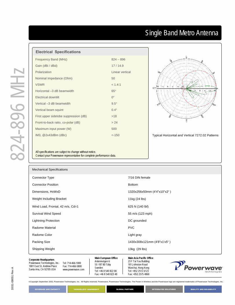
Typical Horizontal and Vertical 7272.02 Patterns
Frequency Band (MHz) 824 – 896
Gain (dBi / dBd) 17 / 14.9
Polarization Linear vertical
Nominal Impedance (Ohm) 50
VSWR < 1.4:1
Horizontal –3 dB beamwidth 65°
Electrical downtilt 0°
Vertical –3 dB beamwidth 9.5°
Vertical beam squint 0.4°
First upper sidelobe suppression (dB) >18
Front-to-back ratio, co-polar (dB) > 24
Maximum input power (W) 500
IM3, @2x43dBm (dBc) <-150
All specifications are subject to change without notice.Contact your Powerwave representative for complete performance data.

65° 1.3 m vertical polarized FET Antenna
Part Number:7273.02
Horizontal Beamwidth: 65°
Gain: 18.0 dBi / 15.9 dBdElectrical Downtilt: 0ºConnector Type: 7/16 DIN female
The Powerwave® Urban Single Band Antenna blends inconspicuously into structural backgrounds due to its slim design. This makes it an ideal choice for built-up areas, whether domestic or commercial. State-of-the-art patch technology allows the antenna’s characteristic flat design. Made from corrosion-resistant aluminum and PVC, its exceptionally rugged design reassures you that every Urban antenna we produce provides reliable, lasting service even in the most demanding environments.
824-
896 M
Hz4168.11.33.00Single Band Urban Antenna
Key Benefits
• Market Leading Performance• Vertical Polarization• Light Weight• Reliable Lasting Service

D03
1-08
052
Rev
A
©Copyright September 2003, Powerwave Technologies, Inc. All Rights reserved. Powerwave, Powerwave Technologies, The Power in Wireless and the Powerwave logo are registered trademarks of Powerwave Technologies, Inc.
Corporate HeadquartersPowerwave Technologies, Inc. 1801 East St. Andrew PlaceSanta Ana, CA 92705 USA
Tel: 714-466-1000Fax: 714-466-5800 www.powerwave.com
Main European OfficeAntennvägen 6SE-187 80 TäbySwedenTel: +46 8 540 822 00Fax: +46 8 540 823 40
Main Asia Pacific Office23 F Tai Yau Building181 Johnston RoadWanchai, Hong KongTel: +852 2512 6123Fax: +852 2575 4860
Single Band Urban Antenna
Electrical Specifications
824-
896 M
Hz
17kg (34.5 lbs) Shipping Weight
1430x308x121mm (4'8"x1'x5" ) Packing Size
Light grayRadome Color
PVCRadome Material
DC groundedLightning Protection
55 m/s (123 mph) Survival Wind Speed
373 N (84 lbf)Wind Load, Frontal, 42 m/s, Cd=1
14kg (31 lbs)Weight Including Bracket
1320x256x50mm (4'4"x10"x2" )Dimensions, HxWxD
BottomConnector Position
7/16 DIN femaleConnector Type
Mechanical Specifications
Typical Horizontal and Vertical 7273.02 Patterns
Frequency Band (MHz) 824 – 896
Gain (dBi / dBd) 18.0 / 15.9
Polarization Linear vertical
Nominal Impedance (Ohm) 50
VSWR < 1.3:1
Horizontal –3 dB beamwidth 65°
Electrical downtilt 0°
Vertical –3 dB beamwidth 7°
First upper sidelobe suppression (dB) >18
Vertical beam squint 0.3°
Front-to-back ratio, co-polar (dB) > 24
First null below horizon (dB) > -22
Maximum input power (W) 500
IM3, @2x43dBm (dBc) <-150
All specifications are subject to change without notice.Contact your Powerwave representative for complete performance data.

65° 2.6 m vertical polarized FET Antenna
Part Number:7273.03
Horizontal Beamwidth: 65°
Gain: 17.5 dBi / 15.4 dBdElectrical Downtilt: 4ºConnector Type: 7/16 DIN female
The Powerwave® Urban Single Band Antenna blends inconspicuously into structural backgrounds due to its slim design. This makes it an ideal choice for built-up areas, whether domestic or commercial. State-of-the-art patch technology allows the antenna’s characteristic flat design. Made from corrosion-resistant aluminum and PVC, its exceptionally rugged design reassures you that every Urban antenna we produce provides reliable, lasting service even in the most demanding environments.
824-
896 M
Hz4168.11.33.00Single Band Urban Antenna
Key Benefits
• Market Leading Performance• Vertical Polarization• Light Weight• Reliable Lasting Service

D03
1-08
128
Rev
A
©Copyright September 2003, Powerwave Technologies, Inc. All Rights reserved. Powerwave, Powerwave Technologies, The Power in Wireless and the Powerwave logo are registered trademarks of Powerwave Technologies, Inc.
Corporate HeadquartersPowerwave Technologies, Inc. 1801 East St. Andrew PlaceSanta Ana, CA 92705 USA
Tel: 714-466-1000Fax: 714-466-5800 www.powerwave.com
Main European OfficeAntennvägen 6SE-187 80 TäbySwedenTel: +46 8 540 822 00Fax: +46 8 540 823 40
Main Asia Pacific Office23 F Tai Yau Building181 Johnston RoadWanchai, Hong KongTel: +852 2512 6123Fax: +852 2575 4860
Single Band Urban Antenna
Electrical Specifications
824-
896 M
Hz
17kg (34.5 lbs) Shipping Weight
2690x308x121mm (8'10"x1'x5")Packing Size
Light grayRadome Color
PVCRadome Material
DC groundedLightning Protection
55 m/s (123 mph) Survival Wind Speed
728 N (164 lbf)Wind Load, Frontal, 42 m/s, Cd=1
14kg (31 lbs)Weight Including Bracket
2580x256x50mm ( 8' 6"x10"x2")Dimensions, HxWxD
BottomConnector Position
7/16 DIN femaleConnector Type
Mechanical Specifications
Typical Horizontal and Vertical 7273.03 Patterns
Frequency Band (MHz) 824 – 896
Gain (dBi / dBd) 17.5 / 15.4
Polarization Linear vertical
Nominal Impedance (Ohm) 50
VSWR < 1.3:1
Horizontal –3 dB beamwidth 65°
Electrical downtilt 4°
Vertical –3 dB beamwidth 7°
First upper sidelobe suppression (dB) >17
Vertical beam squint < 0.3°
Front-to-back ratio, co-polar (dB) > 22
First null below horizon (dB) > -22
Maximum input power (W) 500
IM3, @2x43dBm (dBc) <-150
All specifications are subject to change without notice.Contact your Powerwave representative for complete performance data.

90° 1.3 m vertical polarized FET Antenna
Part Number:7276.02
Horizontal Beamwidth: 90°
Gain: 14.0 dBi / 11.9 dBdElectrical Downtilt: 0ºConnector Type: 7/16 DIN female
The Powerwave® Urban Single Band Antenna blends inconspicuously into structural backgrounds due to its slim design. This makes it an ideal choice for built-up areas, whether domestic or commercial. State-of-the-art patch technology allows the antenna’s characteristic flat design. Made from corrosion-resistant aluminum and PVC, its exceptionally rugged design reassures you that every Urban antenna we produce provides reliable, lasting service even in the most demanding environments.
824-
896 M
Hz4168.11.33.00Single Band Urban Antenna
Key Benefits
• Market Leading Performance• Vertical Polarization• Light Weight• Reliable Lasting Service

D03
1-08
129
Rev
A
©Copyright September 2003, Powerwave Technologies, Inc. All Rights reserved. Powerwave, Powerwave Technologies, The Power in Wireless and the Powerwave logo are registered trademarks of Powerwave Technologies, Inc.
Corporate HeadquartersPowerwave Technologies, Inc. 1801 East St. Andrew PlaceSanta Ana, CA 92705 USA
Tel: 714-466-1000Fax: 714-466-5800 www.powerwave.com
Main European OfficeAntennvägen 6SE-187 80 TäbySwedenTel: +46 8 540 822 00Fax: +46 8 540 823 40
Main Asia Pacific Office23 F Tai Yau Building181 Johnston RoadWanchai, Hong KongTel: +852 2512 6123Fax: +852 2575 4860
Single Band Urban Antenna
Electrical Specifications
824-
896 M
Hz
7,5kg (16.5lbs)Shipping Weight
1430x216x156mm (4'8"x8"x6")Packing Size
Light grayRadome Color
PVCRadome Material
DC groundedLightning Protection
55 m/s (123 mph) Survival Wind Speed
233 N (52 lbf)Wind Load, Frontal, 42 m/s, Cd=1
6kg (13lbs)Weight Including Bracket
1320x160x55mm (4'4"x6"x2")Dimensions, HxWxD
BottomConnector Position
7/16 DIN femaleConnector Type
Mechanical Specifications
Typical Horizontal and Vertical 7276.02 Patterns
Frequency Band (MHz) 824 – 896
Gain (dBi / dBd) 14.0 / 11.9
Polarization Linear vertical
Nominal Impedance (Ohm) 50
VSWR < 1.3:1
Horizontal –3 dB beamwidth 90°
Electrical downtilt 0°
Vertical –3 dB beamwidth 14.5°
First upper sidelobe suppression (dB) >17
Vertical beam squint < 0.4°
Front-to-back ratio, co-polar (dB) > 20
Maximum input power (W) 500
IM3, @2x43dBm (dBc) <-150
All specifications are subject to change without notice.Contact your Powerwave representative for complete performance data.

90° 1.9 m vertical polarized FET Antenna
Part Number:7277.02
Horizontal Beamwidth: 90°
Gain: 15.0 dBi / 12.9 dBdElectrical Downtilt: 0ºConnector Type: 7/16 DIN female
The Powerwave® Urban Single Band Antenna blends inconspicuously into structural backgrounds due to its slim design. This makes it an ideal choice for built-up areas, whether domestic or commercial. State-of-the-art patch technology allows the antenna’s characteristic flat design. Made from corrosion-resistant aluminum and PVC, its exceptionally rugged design reassures you that every Urban antenna we produce provides reliable, lasting service even in the most demanding environments.
824-
896 M
Hz4168.11.33.00Single Band Urban Antenna
Key Benefits
• Market Leading Performance• Vertical Polarization• Light Weight• Reliable Lasting Service
D03
1-08
131
Rev
A
©Copyright September 2003, Powerwave Technologies, Inc. All Rights reserved. Powerwave, Powerwave Technologies, The Power in Wireless and the Powerwave logo are registered trademarks of Powerwave Technologies, Inc.
Corporate HeadquartersPowerwave Technologies, Inc. 1801 East St. Andrew PlaceSanta Ana, CA 92705 USA
Tel: 714-466-1000Fax: 714-466-5800 www.powerwave.com
Main European OfficeAntennvägen 6SE-187 80 TäbySwedenTel: +46 8 540 822 00Fax: +46 8 540 823 40
Main Asia Pacific Office23 F Tai Yau Building181 Johnston RoadWanchai, Hong KongTel: +852 2512 6123Fax: +852 2575 4860
Single Band Urban Antenna
Electrical Specifications
824-
896 M
Hz
12kg (26.5lbs)Shipping Weight
2050x216x156mm (6‘9"x8"x6")Packing Size
Light grayRadome Color
PVCRadome Material
DC groundedLightning Protection
55 m/s (123 mph) Survival Wind Speed
342 N (77 lbf)Wind Load, Frontal, 42 m/s, Cd=1
9kg (20lbs)Weight Including Bracket
1940x160x55mm (6'4"x6"x2")Dimensions, HxWxD
BottomConnector Position
7/16 DIN femaleConnector Type
Mechanical Specifications
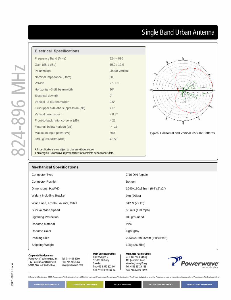
Typical Horizontal and Vertical 7277.02 Patterns
Frequency Band (MHz) 824 – 896
Gain (dBi / dBd) 15.0 / 12.9
Polarization Linear vertical
Nominal Impedance (Ohm) 50
VSWR < 1.3:1
Horizontal –3 dB beamwidth 90°
Electrical downtilt 0°
Vertical –3 dB beamwidth 9.5°
First upper sidelobe suppression (dB) >17
Vertical beam squint < 0.3°
Front-to-back ratio, co-polar (dB) > 21
First null below horizon (dB) > -15
Maximum input power (W) 500
IM3, @2x43dBm (dBc) <-150
All specifications are subject to change without notice.Contact your Powerwave representative for complete performance data.

90° 2.6 m vertical polarized FET Antenna
Part Number:7278.02
Horizontal Beamwidth: 90°
Gain: 16.0 dBi / 13.9 dBdElectrical Downtilt: 0ºConnector Type: 7/16 DIN female
The Powerwave® Urban Single Band Antenna blends inconspicuously into structural backgrounds due to its slim design. This makes it an ideal choice for built-up areas, whether domestic or commercial. State-of-the-art patch technology allows the antenna’s characteristic flat design. Made from corrosion-resistant aluminum and PVC, its exceptionally rugged design reassures you that every Urban antenna we produce provides reliable, lasting service even in the most demanding environments.
824-
896 M
Hz4168.11.33.00Single Band Urban Antenna
Key Benefits
• Market Leading Performance• Vertical Polarization• Light Weight• Reliable Lasting Service
D03
1-08
130
Rev
A
©Copyright September 2003, Powerwave Technologies, Inc. All Rights reserved. Powerwave, Powerwave Technologies, The Power in Wireless and the Powerwave logo are registered trademarks of Powerwave Technologies, Inc.
Corporate HeadquartersPowerwave Technologies, Inc. 1801 East St. Andrew PlaceSanta Ana, CA 92705 USA
Tel: 714-466-1000Fax: 714-466-5800 www.powerwave.com
Main European OfficeAntennvägen 6SE-187 80 TäbySwedenTel: +46 8 540 822 00Fax: +46 8 540 823 40
Main Asia Pacific Office23 F Tai Yau Building181 Johnston RoadWanchai, Hong KongTel: +852 2512 6123Fax: +852 2575 4860
Single Band Urban Antenna
Electrical Specifications
824-
896 M
Hz
14kg (31lbs)Shipping Weight
2690x216x156mm (8‘10"x8"x6")Packing Size
Light grayRadome Color
PVCRadome Material
DC groundedLightning Protection
55 m/s (123 mph) Survival Wind Speed
455 N (102 lbf)Wind Load, Frontal, 42 m/s, Cd=1
11kg (24lbs)Weight Including Bracket
2580x160x55mm (8‘6"x6"x2")Dimensions, HxWxD
BottomConnector Position
7/16 DIN femaleConnector Type
Mechanical Specifications
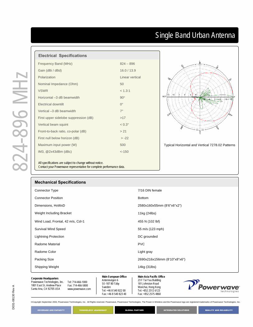
Typical Horizontal and Vertical 7278.02 Patterns
Frequency Band (MHz) 824 – 896
Gain (dBi / dBd) 16.0 / 13.9
Polarization Linear vertical
Nominal Impedance (Ohm) 50
VSWR < 1.3:1
Horizontal –3 dB beamwidth 90°
Electrical downtilt 0°
Vertical –3 dB beamwidth 7°
First upper sidelobe suppression (dB) >17
Vertical beam squint < 0.3°
Front-to-back ratio, co-polar (dB) > 21
First null below horizon (dB) > -22
Maximum input power (W) 500
IM3, @2x43dBm (dBc) <-150
All specifications are subject to change without notice.Contact your Powerwave representative for complete performance data.
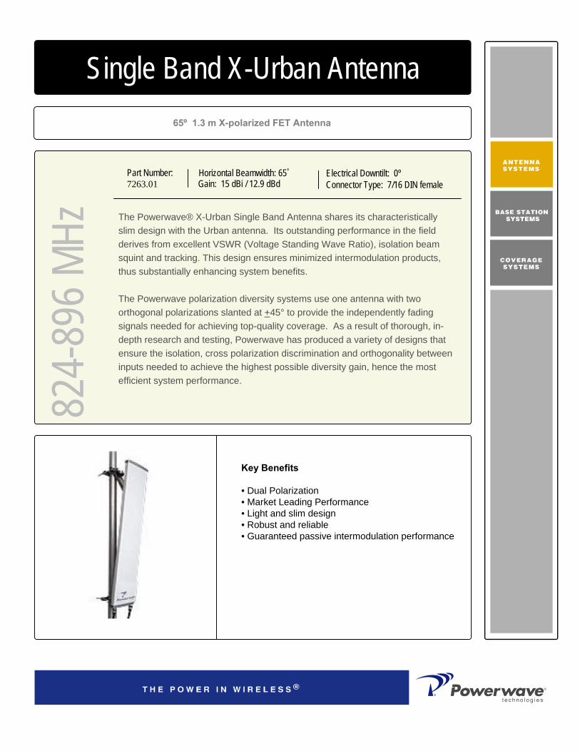
65º 1.3 m X-polarized FET Antenna
Part Number:7263.01
Horizontal Beamwidth: 65°
Gain: 15 dBi / 12.9 dBdElectrical Downtilt: 0ºConnector Type: 7/16 DIN female
The Powerwave® X-Urban Single Band Antenna shares its characteristically slim design with the Urban antenna. Its outstanding performance in the field derives from excellent VSWR (Voltage Standing Wave Ratio), isolation beam squint and tracking. This design ensures minimized intermodulation products, thus substantially enhancing system benefits.
The Powerwave polarization diversity systems use one antenna with two orthogonal polarizations slanted at +45° to provide the independently fading signals needed for achieving top-quality coverage. As a result of thorough, in-depth research and testing, Powerwave has produced a variety of designs that ensure the isolation, cross polarization discrimination and orthogonality between inputs needed to achieve the highest possible diversity gain, hence the most efficient system performance.
824-
896 M
Hz4168.11.33.00Single Band X-Urban Antenna
Key Benefits
• Dual Polarization• Market Leading Performance• Light and slim design• Robust and reliable• Guaranteed passive intermodulation performance

D03
1-08
126
Rev
A
©Copyright September 2003, Powerwave Technologies, Inc. All Rights reserved. Powerwave, Powerwave Technologies, The Power in Wireless and the Powerwave logo are registered trademarks of Powerwave Technologies, Inc.
Corporate HeadquartersPowerwave Technologies, Inc. 1801 East St. Andrew PlaceSanta Ana, CA 92705 USA
Tel: 714-466-1000Fax: 714-466-5800 www.powerwave.com
Main European OfficeAntennvägen 6SE-187 80 TäbySwedenTel: +46 8 540 822 00Fax: +46 8 540 823 40
Main Asia Pacific Office23 F Tai Yau Building181 Johnston RoadWanchai, Hong KongTel: +852 2512 6123Fax: +852 2575 4860
Single Band X-Urban Antenna
Electrical Specifications
824-
896 M
Hz
8.5 kg (19 lbs)Shipping Weight
1430x308x121mm (56” x 12” x 5” )Packing Size
Light grayRadome Color
PVCRadome Material
DC groundedLightning Protection
55 m/s (123 mph)Survival Wind Speed
419 N (256 lbf)Wind Load, Frontal, 42 m/s, Cd=1
7.5 kg (16.5 lbs)Weight Including Bracket
1320x256x50mm (52“ x 10.4” x2” )Dimensions, HxWxD
BottomConnector Position
7/16 DIN femaleConnector Type
Mechanical Specifications
Typical Horizontal and Vertical 7263.01 Patterns
Frequency Band (MHz) 824 – 896Gain (dBi / dBd) 15 / 12.9Polarization Linear slanted ± 45°Nominal Impedance (Ohm) 50VSWR < 1.4:1Isolation between inputs (dB) > 30Horizontal –3 dB beamwidth 65°Tracking, Horizontal plane (dB) < 0.5 Electrical downtilt 0°Vertical –3 dB beamwidth 13°First upper sidelobe suppression (dB) > 14Vertical beam squint < 0.3°Front-to-back ratio, co-polar (dB) >22Cross-polar discrimination (dB) >18Maximum input power (W) 500IM3, @2x43dBm (dBc) <-150
All specifications are subject to change without notice.Contact your Powerwave representative for complete performance data.

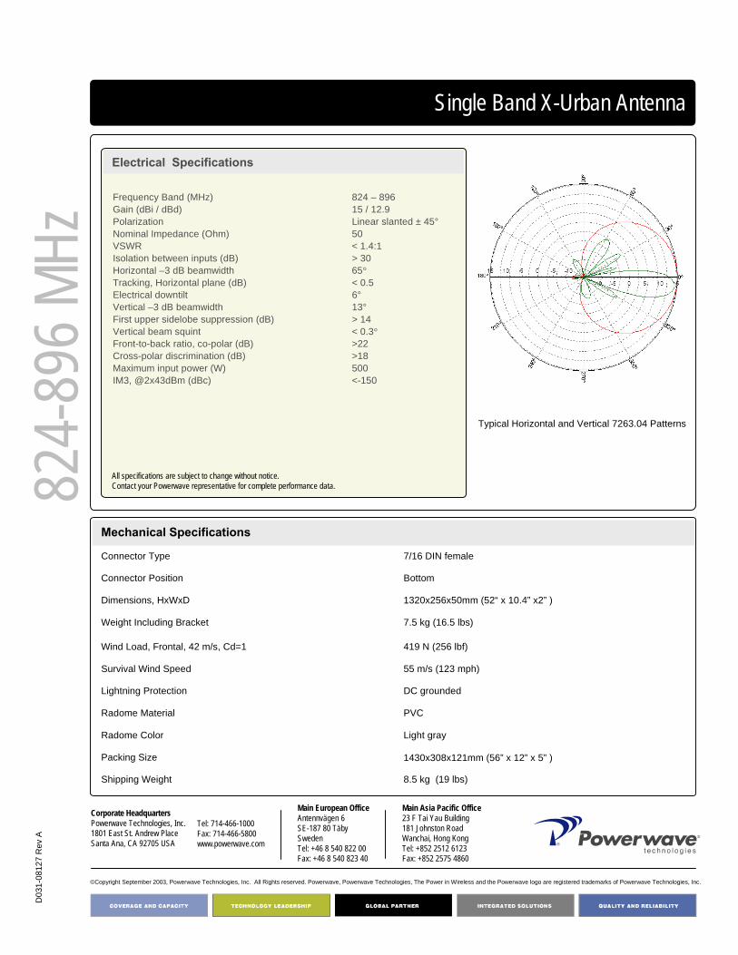
65º 1.3 m X-polarized FET Antenna
Part Number:7263.04
Horizontal Beamwidth: 65°
Gain: 15 dBi / 12.9 dBdElectrical Downtilt: 6ºConnector Type: 7/16 DIN female
The Powerwave® X-Urban Single Band Antenna shares its characteristically slim design with the Urban antenna. Its outstanding performance in the field derives from excellent VSWR (Voltage Standing Wave Ratio), isolation beam squint and tracking. This design ensures minimized intermodulation products, thus substantially enhancing system benefits.
The Powerwave polarization diversity systems use one antenna with two orthogonal polarizations slanted at +45° to provide the independently fading signals needed for achieving top-quality coverage. As a result of thorough, in-depth research and testing, Powerwave has produced a variety of designs that ensure the isolation, cross polarization discrimination and orthogonality between inputs needed to achieve the highest possible diversity gain, hence the most efficient system performance.
824-
896 M
Hz4168.11.33.00Single Band X-Urban Antenna
Key Benefits
• Dual Polarization• Market Leading Performance• Light and slim design• Robust and reliable• Guaranteed passive intermodulation performance
D03
1-08
127
Rev
A
©Copyright September 2003, Powerwave Technologies, Inc. All Rights reserved. Powerwave, Powerwave Technologies, The Power in Wireless and the Powerwave logo are registered trademarks of Powerwave Technologies, Inc.
Corporate HeadquartersPowerwave Technologies, Inc. 1801 East St. Andrew PlaceSanta Ana, CA 92705 USA
Tel: 714-466-1000Fax: 714-466-5800 www.powerwave.com
Main European OfficeAntennvägen 6SE-187 80 TäbySwedenTel: +46 8 540 822 00Fax: +46 8 540 823 40
Main Asia Pacific Office23 F Tai Yau Building181 Johnston RoadWanchai, Hong KongTel: +852 2512 6123Fax: +852 2575 4860
Single Band X-Urban Antenna
Electrical Specifications
824-
896 M
Hz
8.5 kg (19 lbs)Shipping Weight
1430x308x121mm (56” x 12” x 5” )Packing Size
Light grayRadome Color
PVCRadome Material
DC groundedLightning Protection
55 m/s (123 mph)Survival Wind Speed
419 N (256 lbf)Wind Load, Frontal, 42 m/s, Cd=1
7.5 kg (16.5 lbs)Weight Including Bracket
1320x256x50mm (52“ x 10.4” x2” )Dimensions, HxWxD
BottomConnector Position
7/16 DIN femaleConnector Type
Mechanical Specifications
Typical Horizontal and Vertical 7263.04 Patterns
Frequency Band (MHz) 824 – 896Gain (dBi / dBd) 15 / 12.9Polarization Linear slanted ± 45°Nominal Impedance (Ohm) 50VSWR < 1.4:1Isolation between inputs (dB) > 30Horizontal –3 dB beamwidth 65°Tracking, Horizontal plane (dB) < 0.5 Electrical downtilt 6°Vertical –3 dB beamwidth 13°First upper sidelobe suppression (dB) > 14Vertical beam squint < 0.3°Front-to-back ratio, co-polar (dB) >22Cross-polar discrimination (dB) >18Maximum input power (W) 500IM3, @2x43dBm (dBc) <-150
All specifications are subject to change without notice.Contact your Powerwave representative for complete performance data.

65° 1.9 m X-polarized FET Antenna
Part Number:7281.02
Horizontal Beamwidth: 65°
Gain: 16.5 dBi / 14.9 dBdElectrical Downtilt: 0ºConnector Type: 7/16 DIN female
The Powerwave® X-Urban Single Band Antenna blends inconspicuously into structural backgrounds due to its slim design. This makes it an ideal choice for built-up areas, whether domestic or commercial. State-of-the-art patch technology allows the antenna’s characteristic flat design. Made from corrosion-resistant aluminum and PVC, its exceptionally rugged design reassures you that every Urban antenna we produce provides reliable, lasting service even in the most demanding environments.
824-
896 M
Hz4168.11.33.00Single Band X-Urban Antenna
Key Benefits
• Market Leading Performance• Vertical Polarization• Light Weight• Reliable Lasting Service

D03
1-08
132
Rev
A
©Copyright September 2003, Powerwave Technologies, Inc. All Rights reserved. Powerwave, Powerwave Technologies, The Power in Wireless and the Powerwave logo are registered trademarks of Powerwave Technologies, Inc.
Corporate HeadquartersPowerwave Technologies, Inc. 1801 East St. Andrew PlaceSanta Ana, CA 92705 USA
Tel: 714-466-1000Fax: 714-466-5800 www.powerwave.com
Main European OfficeAntennvägen 6SE-187 80 TäbySwedenTel: +46 8 540 822 00Fax: +46 8 540 823 40
Main Asia Pacific Office23 F Tai Yau Building181 Johnston RoadWanchai, Hong KongTel: +852 2512 6123Fax: +852 2575 4860
Single Band X-Urban Antenna
Electrical Specifications
824-
896 M
Hz
10kg (22lbs)Shipping Weight
2050x308x121mm (6'9"x1'x5')Packing Size
Light grayRadome Color
PVCRadome Material
DC groundedLightning Protection
55 m/s (123 mph) Survival Wind Speed
547 N (123 lbf)Wind Load, Frontal, 42 m/s, Cd=1
9kg (20lbs)Weight Including Bracket
1939x256x50mm (6'4"x10"x2")Dimensions, HxWxD
BottomConnector Position
7/16 DIN femaleConnector Type
Mechanical Specifications
Typical Horizontal and Vertical 7281.02 Patterns
Frequency Band (MHz) 824 – 896
Gain (dBi / dBd) 16.5 / 14.4
Polarization Linear vertical
Nominal Impedance (Ohm) 50
VSWR < 1.3:1
Isolation between inputs (dB) > 30
Horizontal –3 dB beamwidth 65°
Horizontal tracking (dB) < 0.5
Electrical downtilt 0°
Vertical –3 dB beamwidth 9°
First upper sidelobe suppression (dB) > 15
Vertical beam squint < 0.3°
Front-to-back ratio, co-polar (dB) > 24
Cross-polar discrimination (dB) > 20
Maximum input power (W) 500
IM3, @2x43dBm (dBc) <-150
All specifications are subject to change without notice.Contact your Powerwave representative for complete performance data.

65° 1.9 m X-polarized FET Antenna
Part Number:7281.04
Horizontal Beamwidth: 65°
Gain: 16.5 dBi / 14.9 dBdElectrical Downtilt: 6ºConnector Type: 7/16 DIN female
The Powerwave® X-Urban Single Band Antenna blends inconspicuously into structural backgrounds due to its slim design. This makes it an ideal choice for built-up areas, whether domestic or commercial. State-of-the-art patch technology allows the antenna’s characteristic flat design. Made from corrosion-resistant aluminum and PVC, its exceptionally rugged design reassures you that every Urban antenna we produce provides reliable, lasting service even in the most demanding environments.
824-
896 M
Hz4168.11.33.00Single Band X-Urban Antenna
Key Benefits
• Market Leading Performance• Vertical Polarization• Light Weight• Reliable Lasting Service

D03
1-08
223
Rev
A
©Copyright September 2003, Powerwave Technologies, Inc. All Rights reserved. Powerwave, Powerwave Technologies, The Power in Wireless and the Powerwave logo are registered trademarks of Powerwave Technologies, Inc.
Corporate HeadquartersPowerwave Technologies, Inc. 1801 East St. Andrew PlaceSanta Ana, CA 92705 USA
Tel: 714-466-1000Fax: 714-466-5800 www.powerwave.com
Main European OfficeAntennvägen 6SE-187 80 TäbySwedenTel: +46 8 540 822 00Fax: +46 8 540 823 40
Main Asia Pacific Office23 F Tai Yau Building181 Johnston RoadWanchai, Hong KongTel: +852 2512 6123Fax: +852 2575 4860
Single Band X-Urban Antenna
Electrical Specifications
824-
896 M
Hz
10kg (22lbs)Shipping Weight
2050x308x121mm (6'9"x1'x5')Packing Size
Light grayRadome Color
PVCRadome Material
DC groundedLightning Protection
55 m/s (123 mph) Survival Wind Speed
547 N (123 lbf)Wind Load, Frontal, 42 m/s, Cd=1
9kg (20lbs)Weight Including Bracket
1939x256x50mm (6'4"x10"x2")Dimensions, HxWxD
BottomConnector Position
7/16 DIN femaleConnector Type
Mechanical Specifications
Typical Horizontal and Vertical 7281.04 Patterns
Frequency Band (MHz) 824 – 896
Gain (dBi / dBd) 16.5 / 14.4
Polarization Linear vertical
Nominal Impedance (Ohm) 50
VSWR < 1.3:1
Isolation between inputs (dB) > 30
Horizontal –3 dB beamwidth 65°
Horizontal tracking (dB) < 0.5
Electrical downtilt 6°
Vertical –3 dB beamwidth 9°
First upper sidelobe suppression (dB) > 14
Vertical beam squint < 0.3°
Front-to-back ratio, co-polar (dB) > 24
Cross-polar discrimination (dB) > 20
Maximum input power (W) 500
IM3, @2x43dBm (dBc) <-150
All specifications are subject to change without notice.Contact your Powerwave representative for complete performance data.

65° 0.7 m vertical polarized FET Antenna
Part Number:7282.03
Horizontal Beamwidth: 65°
Gain: 12.5 dBi / 10.4 dBdElectrical Downtilt: 4ºConnector Type: 7/16 DIN female
The Powerwave® X-Urban Single Band Antenna blends inconspicuously into structural backgrounds due to its slim design. This makes it an ideal choice for built-up areas, whether domestic or commercial. State-of-the-art patch technology allows the antenna’s characteristic flat design. Made from corrosion-resistant aluminum and PVC, its exceptionally rugged design reassures you that every Urban antenna we produce provides reliable, lasting service even in the most demanding environments.
824-
896 M
Hz4168.11.33.00Single Band X-Urban Antenna
Key Benefits
• Market Leading Performance• Vertical Polarization• Light Weight• Reliable Lasting Service

D03
1-08
142
Rev
A
©Copyright September 2003, Powerwave Technologies, Inc. All Rights reserved. Powerwave, Powerwave Technologies, The Power in Wireless and the Powerwave logo are registered trademarks of Powerwave Technologies, Inc.
Corporate HeadquartersPowerwave Technologies, Inc. 1801 East St. Andrew PlaceSanta Ana, CA 92705 USA
Tel: 714-466-1000Fax: 714-466-5800 www.powerwave.com
Main European OfficeAntennvägen 6SE-187 80 TäbySwedenTel: +46 8 540 822 00Fax: +46 8 540 823 40
Main Asia Pacific Office23 F Tai Yau Building181 Johnston RoadWanchai, Hong KongTel: +852 2512 6123Fax: +852 2575 4860
Single Band X-Urban Antenna
Electrical Specifications
824-
896 M
Hz
5kg (11lbs)Shipping Weight
750x308x121mm (2'6"x1'x5')Packing Size
Light grayRadome Color
PVCRadome Material
DC groundedLightning Protection
55 m/s (123 mph) Survival Wind Speed
5186 N (42 lbf)Wind Load, Frontal, 42 m/s, Cd=1
4kg (9lbs)Weight Including Bracket
659x256x50mm (2'2"x10"x2")Dimensions, HxWxD
BottomConnector Position
7/16 DIN femaleConnector Type
Mechanical Specifications
Typical Horizontal and Vertical 7282.03 Patterns
Frequency Band (MHz) 824 – 896
Gain (dBi / dBd) 12.5 / 10.4
Polarization Linear vertical
Nominal Impedance (Ohm) 50
VSWR < 1.3:1
Isolation between inputs (dB) > 30
Horizontal –3 dB beamwidth 65°
Horizontal tracking (dB) < 0.5
Electrical downtilt 4°
Vertical –3 dB beamwidth 25°
First upper sidelobe suppression (dB) > 9
Vertical beam squint < 0.3°
Front-to-back ratio, co-polar (dB) > 22
Cross-polar discrimination (dB) > 20
Maximum input power (W) 250
IM3, @2x43dBm (dBc) <-150
All specifications are subject to change without notice.Contact your Powerwave representative for complete performance data.

40° 1.4 m vertical-polarized FET Antenna
4168.11.33.00Broadband ALP Antenna80
6-96
0 MHz The new Powerwave log periodic antennas have a narrower profile than our
previous models. We replaced the previous 110 degree log periodic elements with a 90 degree log periodic element. The Powerwave log periodic is manufactured in a highly repeatable process that is so precise that absolutely no tuning is required. For long life and problem free performance, we use a robust mechanical design that includes high-strength plates of aircraft quality aluminum used to form an extremely rugged package. In addition, the mechanical strength is independent of the random, which acts only to physically protect and form a weather shield for the elements.
Key Benefits:
• Cutting Edge Network Performance• Reduced Logistic Costs• High Volume Capability
Part Number7804.00R2A
Horizontal Beamwidth: 40°
Gain: 17 dBi / 14.9 dBdElectrical Downtilt: 0°
Connector Type: DIN

D03
1-08
026
Rev
A
Corporate HeadquartersPowerwave Technologies, Inc. 1801 East St. Andrew PlaceSanta Ana, CA 92705 USA
Tel: 714-466-1000Fax: 714-466-5800 www.powerwave.com
Main European OfficeAntennvägen 6SE-187 80 TäbySwedenTel: +46 8 540 822 00Fax: +46 8 540 823 40
Main Asia Pacific Office23 F Tai Yau Building181 Johnston RoadWanchai, Hong KongTel: +852 2512 6123Fax: +852 2575 4860
©Copyright September 2003, Powerwave Technologies, Inc. All Rights reserved. Powerwave, Powerwave Technologies, The Power in Wireless and the Powerwave logo are registered trademarks of Powerwave Technologies, Inc.
Broadband ALP Antenna80
6-96
0 MHz
40°Horizontal -3 dB beamwidth
14°Vertical -3 dB beamwidth
0°Electrical downtilt
>35Front-to-back ratio (dB)
>18First upper sidelobe suppression (dB)
500Maximum input power (W)
<-146IM, 3rd order, @2x43dBm (dBc)
<1.4:1VSWR
50Nominal Impedence (Ohm)
17 / 14.9Gain (dBi) / (dBd)
Linear verticalPolarization
806-960Frequency Range (MHz)
Electrical Specifications
17.3 kg (38 lbs) Shipping Weight
1389x627x394mm (4’7”x2’1”x1’4” )Packing Size
Light GrayRadome Color
PVCRadome Material
DC groundedLightning Protection
70m/s (156 mph)Survival Wind Speed
859 N ( 193 lbf)Wind Load, Frontal, 42 m/s
14.6 kg (31 lbs) Weight including Bracket
11 kg (23.2 lbs)Weight without Bracket
1320x590x350mm (4’4”x1’11”x1’2” )Dimensions, HxWxD
BackConnector Position
7/16 DIN femaleConnector Type
Mechanical Specifications
Typical Horizontal and Vertical7804.00R2APatterns
All specifications are subject to change without notice.Contact your Powerwave representative for complete performance data.

65° 0.7 m vertical polarized FET Antenna
Part Number:7225.04
Horizontal Beamwidth: 65°
Gain: 13 dBi / 10.9 dBdElectrical Downtilt: 0ºConnector Type: 7/16 DIN female
The Powerwave® Urban Single Band Antenna blends inconspicuously into structural backgrounds due to its slim design. This makes it an ideal choice for built-up areas, whether domestic or commercial. State-of-the-art patch technology allows the antenna’s characteristic flat design. Made from corrosion-resistant aluminum and PVC, its exceptionally rugged design reassures you that every Urban antenna we produce provides reliable, lasting service even in the most demanding environments.
870-
960 M
Hz4168.11.33.00Single Band Urban Antenna
Key Benefits
• Market Leading Performance• Vertical Polarization• Light Weight• Reliable Lasting Service

D03
1-08
055
Rev
A
©Copyright September 2003, Powerwave Technologies, Inc. All Rights reserved. Powerwave, Powerwave Technologies, The Power in Wireless and the Powerwave logo are registered trademarks of Powerwave Technologies, Inc.
Corporate HeadquartersPowerwave Technologies, Inc. 1801 East St. Andrew PlaceSanta Ana, CA 92705 USA
Tel: 714-466-1000Fax: 714-466-5800 www.powerwave.com
Main European OfficeAntennvägen 6SE-187 80 TäbySwedenTel: +46 8 540 822 00Fax: +46 8 540 823 40
Main Asia Pacific Office23 F Tai Yau Building181 Johnston RoadWanchai, Hong KongTel: +852 2512 6123Fax: +852 2575 4860
Single Band Urban Antenna
Electrical Specifications
870-
960 M
Hz
6kg (13 lbs)Shipping Weight
770x308x121mm (2’6”x1’x5”)Packing Size
Light grayRadome Color
PVCRadome Material
DC groundedLightning Protection
55 m/s (123 mph) Survival Wind Speed
190 m/s (43 lbf)Wind Load, Frontal, 42 m/s, Cd=1
5kg (11 lbs)Weight Including Bracket
660x256x50mm (4’4”x10”x2”)Dimensions, HxWxD
BottomConnector Position
7/16 DIN femaleConnector Type
Mechanical Specifications
Typical Horizontal and Vertical 7225.04 Patterns
Frequency Band (MHz) 870 – 960
Gain (dBi / dBd) 13 / 10.9
Polarization Linear vertical
Nominal Impedance (Ohm) 50
VSWR < 1.3.1
Horizontal –3 dB beamwidth 65°
Electrical downtilt 0°
Vertical –3 dB beamwidth 26°
First upper sidelobe suppression (dB) >9
Front-to-back ratio, co-polar (dB) > 25
Maximum input power (W) 300
IM3, @2x43dBm (dBc) <-150
All specifications are subject to change without notice.Contact your Powerwave representative for complete performance data.
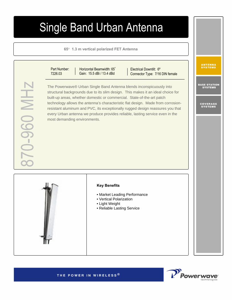
65° 1.3 m vertical polarized FET Antenna
Part Number:7226.03
Horizontal Beamwidth: 65°
Gain: 15.5 dBi / 13.4 dBdElectrical Downtilt: 6ºConnector Type: 7/16 DIN female
The Powerwave® Urban Single Band Antenna blends inconspicuously into structural backgrounds due to its slim design. This makes it an ideal choice for built-up areas, whether domestic or commercial. State-of-the-art patch technology allows the antenna’s characteristic flat design. Made from corrosion-resistant aluminum and PVC, its exceptionally rugged design reassures you that every Urban antenna we produce provides reliable, lasting service even in the most demanding environments.
870-
960 M
Hz4168.11.33.00Single Band Urban Antenna
Key Benefits
• Market Leading Performance• Vertical Polarization• Light Weight• Reliable Lasting Service

D03
1-08
055
Rev
A
©Copyright September 2003, Powerwave Technologies, Inc. All Rights reserved. Powerwave, Powerwave Technologies, The Power in Wireless and the Powerwave logo are registered trademarks of Powerwave Technologies, Inc.
Corporate HeadquartersPowerwave Technologies, Inc. 1801 East St. Andrew PlaceSanta Ana, CA 92705 USA
Tel: 714-466-1000Fax: 714-466-5800 www.powerwave.com
Main European OfficeAntennvägen 6SE-187 80 TäbySwedenTel: +46 8 540 822 00Fax: +46 8 540 823 40
Main Asia Pacific Office23 F Tai Yau Building181 Johnston RoadWanchai, Hong KongTel: +852 2512 6123Fax: +852 2575 4860
Single Band Urban Antenna
Electrical Specifications
870-
960 M
Hz
8.5kg (18 lbs)Shipping Weight
1430x308x121mm (4’8”x1’x5”)Packing Size
Light grayRadome Color
PVCRadome Material
DC groundedLightning Protection
55 m/s (123 mph) Survival Wind Speed
373 m/s (84 lbf)Wind Load, Frontal, 42 m/s, Cd=1
7kg (15 lbs)Weight Including Bracket
1320x256x50mm (4’4”x10”x2”)Dimensions, HxWxD
BottomConnector Position
7/16 DIN femaleConnector Type
Mechanical Specifications
Typical Horizontal and Vertical 7226.03 Patterns
Frequency Band (MHz) 870 – 960
Gain (dBi / dBd) 15.5 / 13.4
Polarization Linear vertical
Nominal Impedance (Ohm) 50
VSWR < 1.3.1
Horizontal –3 dB beamwidth 65°
Electrical downtilt 6°
Vertical –3 dB beamwidth 14°
First upper sidelobe suppression (dB) >17
Front-to-back ratio, co-polar (dB) > 25
Maximum input power (W) 500
IM3, @2x43dBm (dBc) <-150
All specifications are subject to change without notice.Contact your Powerwave representative for complete performance data.

65° 1.3 m vertical polarized FET Antenna
Part Number:7226.04
Horizontal Beamwidth: 65°
Gain: 15.5 dBi / 13.4 dBdElectrical Downtilt: 0ºConnector Type: 7/16 DIN female
The Powerwave® Urban Single Band Antenna blends inconspicuously into structural backgrounds due to its slim design. This makes it an ideal choice for built-up areas, whether domestic or commercial. State-of-the-art patch technology allows the antenna’s characteristic flat design. Made from corrosion-resistant aluminum and PVC, its exceptionally rugged design reassures you that every Urban antenna we produce provides reliable, lasting service even in the most demanding environments.
870-
960 M
Hz4168.11.33.00Single Band Urban Antenna
Key Benefits
• Market Leading Performance• Vertical Polarization• Light Weight• Reliable Lasting Service

D03
1-08
056
Rev
A
©Copyright September 2003, Powerwave Technologies, Inc. All Rights reserved. Powerwave, Powerwave Technologies, The Power in Wireless and the Powerwave logo are registered trademarks of Powerwave Technologies, Inc.
Corporate HeadquartersPowerwave Technologies, Inc. 1801 East St. Andrew PlaceSanta Ana, CA 92705 USA
Tel: 714-466-1000Fax: 714-466-5800 www.powerwave.com
Main European OfficeAntennvägen 6SE-187 80 TäbySwedenTel: +46 8 540 822 00Fax: +46 8 540 823 40
Main Asia Pacific Office23 F Tai Yau Building181 Johnston RoadWanchai, Hong KongTel: +852 2512 6123Fax: +852 2575 4860
Single Band Urban Antenna
Electrical Specifications
870-
960 M
Hz
8.5kg (18 lbs)Shipping Weight
1430x308x121mm (4’8”x1’x5”)Packing Size
Light grayRadome Color
PVCRadome Material
DC groundedLightning Protection
55 m/s (123 mph) Survival Wind Speed
373 m/s (84 lbf)Wind Load, Frontal, 42 m/s, Cd=1
7kg (15 lbs)Weight Including Bracket
1320x256x50mm (4’4”x10”x2”)Dimensions, HxWxD
BottomConnector Position
7/16 DIN femaleConnector Type
Mechanical Specifications
Typical Horizontal and Vertical 7226.04 Patterns
Frequency Band (MHz) 870 – 960
Gain (dBi / dBd) 15.5 / 13.4
Polarization Linear vertical
Nominal Impedance (Ohm) 50
VSWR < 1.3.1
Horizontal –3 dB beamwidth 65°
Electrical downtilt 0°
Vertical –3 dB beamwidth 14°
First upper sidelobe suppression (dB) >17
Front-to-back ratio, co-polar (dB) > 23
Maximum input power (W) 500
IM3, @2x43dBm (dBc) <-150
All specifications are subject to change without notice.Contact your Powerwave representative for complete performance data.

65° 1.9 m vertical polarized FET Antenna
Part Number:7227.03, 7227.13
Horizontal Beamwidth: 65°
Gain: 17.0 dBi / 14.9 dBdElectrical Downtilt: 6ºConnector Type: 7/16 DIN female
The Powerwave® Urban Single Band Antenna blends inconspicuously into structural backgrounds due to its slim design. This makes it an ideal choice for built-up areas, whether domestic or commercial. State-of-the-art patch technology allows the antenna’s characteristic flat design. Made from corrosion-resistant aluminum and PVC, its exceptionally rugged design reassures you that every Urban antenna we produce provides reliable, lasting service even in the most demanding environments.
870-
960 M
Hz4168.11.33.00Single Band Urban Antenna
Key Benefits
• Market Leading Performance• Vertical Polarization• Light Weight• Reliable Lasting Service

D03
1-08
057
Rev
A
©Copyright September 2003, Powerwave Technologies, Inc. All Rights reserved. Powerwave, Powerwave Technologies, The Power in Wireless and the Powerwave logo are registered trademarks of Powerwave Technologies, Inc.
Corporate HeadquartersPowerwave Technologies, Inc. 1801 East St. Andrew PlaceSanta Ana, CA 92705 USA
Tel: 714-466-1000Fax: 714-466-5800 www.powerwave.com
Main European OfficeAntennvägen 6SE-187 80 TäbySwedenTel: +46 8 540 822 00Fax: +46 8 540 823 40
Main Asia Pacific Office23 F Tai Yau Building181 Johnston RoadWanchai, Hong KongTel: +852 2512 6123Fax: +852 2575 4860
Single Band Urban Antenna
Electrical Specifications
870-
960 M
Hz
13kg (29 lbs)Shipping Weight
2050x308x121mm (6’9”x1’x5”)Packing Size
Light grayRadome Color
PVCRadome Material
DC groundedLightning Protection
55 m/s (123 mph) Survival Wind Speed
548 m/s (123 lbf)Wind Load, Frontal, 42 m/s, Cd=1
11kg (24 lbs)Weight Including Bracket
1940x256x50mm (6’4”x10”x2”)Dimensions, HxWxD
BottomConnector Position
7/16 DIN femaleConnector Type
Mechanical Specifications
Typical Horizontal and Vertical 7227.04 Patterns
Frequency Band (MHz) 870 – 960
Gain (dBi / dBd) 17.0 / 14.9
Polarization Linear vertical
Nominal Impedance (Ohm) 50
VSWR < 1.3.1
Horizontal –3 dB beamwidth 65°
Electrical downtilt 6°
Vertical –3 dB beamwidth 9°
First upper sidelobe suppression (dB) >18
Front-to-back ratio, co-polar (dB) > 24
First Null below horizon (dB) >-16
Maximum input power (W) 500
IM3, @2x43dBm (dBc) <-150
All specifications are subject to change without notice.Contact your Powerwave representative for complete performance data.

65° 1.9 m vertical polarized FET Antenna
Part Number:7227.04, 7227.14
Horizontal Beamwidth: 65°
Gain: 17.0 dBi / 14.9 dBdElectrical Downtilt: 0ºConnector Type: 7/16 DIN female
The Powerwave® Urban Single Band Antenna blends inconspicuously into structural backgrounds due to its slim design. This makes it an ideal choice for built-up areas, whether domestic or commercial. State-of-the-art patch technology allows the antenna’s characteristic flat design. Made from corrosion-resistant aluminum and PVC, its exceptionally rugged design reassures you that every Urban antenna we produce provides reliable, lasting service even in the most demanding environments.
870-
960 M
Hz4168.11.33.00Single Band Urban Antenna
Key Benefits
• Market Leading Performance• Vertical Polarization• Light Weight• Reliable Lasting Service

D03
1-08
057
Rev
A
©Copyright September 2003, Powerwave Technologies, Inc. All Rights reserved. Powerwave, Powerwave Technologies, The Power in Wireless and the Powerwave logo are registered trademarks of Powerwave Technologies, Inc.
Corporate HeadquartersPowerwave Technologies, Inc. 1801 East St. Andrew PlaceSanta Ana, CA 92705 USA
Tel: 714-466-1000Fax: 714-466-5800 www.powerwave.com
Main European OfficeAntennvägen 6SE-187 80 TäbySwedenTel: +46 8 540 822 00Fax: +46 8 540 823 40
Main Asia Pacific Office23 F Tai Yau Building181 Johnston RoadWanchai, Hong KongTel: +852 2512 6123Fax: +852 2575 4860
Single Band Urban Antenna
Electrical Specifications
870-
960 M
Hz
13kg (29 lbs)Shipping Weight
2050x308x121mm (6’9”x1’x5”)Packing Size
Light grayRadome Color
PVCRadome Material
DC groundedLightning Protection
55 m/s (123 mph) Survival Wind Speed
548 m/s (123 lbf)Wind Load, Frontal, 42 m/s, Cd=1
11kg (24 lbs)Weight Including Bracket
1940x256x50mm (6’4”x10”x2”)Dimensions, HxWxD
BottomConnector Position
7/16 DIN femaleConnector Type
Mechanical Specifications
Typical Horizontal and Vertical 7227.04 Patterns
Frequency Band (MHz) 870 – 960
Gain (dBi / dBd) 17.0 / 14.9
Polarization Linear vertical
Nominal Impedance (Ohm) 50
VSWR < 1.3.1
Horizontal –3 dB beamwidth 65°
Electrical downtilt 0°
Vertical –3 dB beamwidth 9°
First upper sidelobe suppression (dB) >17
Front-to-back ratio, co-polar (dB) > 23
First Null below horizon (dB) >-13
Maximum input power (W) 500
IM3, @2x43dBm (dBc) <-150
All specifications are subject to change without notice.Contact your Powerwave representative for complete performance data.

65° 1.9 m vertical polarized FET Antenna
Part Number:7227.06, 7227.16
Horizontal Beamwidth: 65°
Gain: 17.0 dBi / 14.9 dBdElectrical Downtilt: 4ºConnector Type: 7/16 DIN female
The Powerwave® Urban Single Band Antenna blends inconspicuously into structural backgrounds due to its slim design. This makes it an ideal choice for built-up areas, whether domestic or commercial. State-of-the-art patch technology allows the antenna’s characteristic flat design. Made from corrosion-resistant aluminum and PVC, its exceptionally rugged design reassures you that every Urban antenna we produce provides reliable, lasting service even in the most demanding environments.
870-
960 M
Hz4168.11.33.00Single Band Urban Antenna
Key Benefits
• Market Leading Performance• Vertical Polarization• Light Weight• Reliable Lasting Service

D03
1-08
057
Rev
A
©Copyright September 2003, Powerwave Technologies, Inc. All Rights reserved. Powerwave, Powerwave Technologies, The Power in Wireless and the Powerwave logo are registered trademarks of Powerwave Technologies, Inc.
Corporate HeadquartersPowerwave Technologies, Inc. 1801 East St. Andrew PlaceSanta Ana, CA 92705 USA
Tel: 714-466-1000Fax: 714-466-5800 www.powerwave.com
Main European OfficeAntennvägen 6SE-187 80 TäbySwedenTel: +46 8 540 822 00Fax: +46 8 540 823 40
Main Asia Pacific Office23 F Tai Yau Building181 Johnston RoadWanchai, Hong KongTel: +852 2512 6123Fax: +852 2575 4860
Single Band Urban Antenna
Electrical Specifications
870-
960 M
Hz
13kg (29 lbs)Shipping Weight
2050x308x121mm (6’9”x1’x5”)Packing Size
Light grayRadome Color
PVCRadome Material
DC groundedLightning Protection
55 m/s (123 mph) Survival Wind Speed
548 m/s (123 lbf)Wind Load, Frontal, 42 m/s, Cd=1
11kg (24 lbs)Weight Including Bracket
1940x256x50mm (6’4”x10”x2”)Dimensions, HxWxD
BottomConnector Position
7/16 DIN femaleConnector Type
Mechanical Specifications
Typical Horizontal and Vertical 7227.04 Patterns
Frequency Band (MHz) 870 – 960
Gain (dBi / dBd) 17.0 / 14.9
Polarization Linear vertical
Nominal Impedance (Ohm) 50
VSWR < 1.3.1
Horizontal –3 dB beamwidth 65°
Electrical downtilt 4°
Vertical –3 dB beamwidth 9°
First upper sidelobe suppression (dB) >17
Front-to-back ratio, co-polar (dB) > 23
First Null below horizon (dB) >-17
Maximum input power (W) 500
IM3, @2x43dBm (dBc) <-150
All specifications are subject to change without notice.Contact your Powerwave representative for complete performance data.
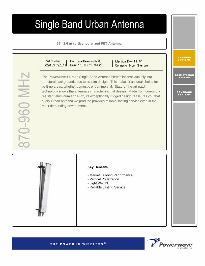
65° 2.6 m vertical polarized FET Antenna
Part Number:7228.03, 7228.13
Horizontal Beamwidth: 65°
Gain: 18.0 dBi / 15.9 dBdElectrical Downtilt: 0ºConnector Type: N female
The Powerwave® Urban Single Band Antenna blends inconspicuously into structural backgrounds due to its slim design. This makes it an ideal choice for built-up areas, whether domestic or commercial. State-of-the-art patch technology allows the antenna’s characteristic flat design. Made from corrosion-resistant aluminum and PVC, its exceptionally rugged design reassures you that every Urban antenna we produce provides reliable, lasting service even in the most demanding environments.
870-
960 M
Hz4168.11.33.00Single Band Urban Antenna
Key Benefits
• Market Leading Performance• Vertical Polarization• Light Weight• Reliable Lasting Service

D03
1-08
124
Rev
A
©Copyright September 2003, Powerwave Technologies, Inc. All Rights reserved. Powerwave, Powerwave Technologies, The Power in Wireless and the Powerwave logo are registered trademarks of Powerwave Technologies, Inc.
Corporate HeadquartersPowerwave Technologies, Inc. 1801 East St. Andrew PlaceSanta Ana, CA 92705 USA
Tel: 714-466-1000Fax: 714-466-5800 www.powerwave.com
Main European OfficeAntennvägen 6SE-187 80 TäbySwedenTel: +46 8 540 822 00Fax: +46 8 540 823 40
Main Asia Pacific Office23 F Tai Yau Building181 Johnston RoadWanchai, Hong KongTel: +852 2512 6123Fax: +852 2575 4860
Single Band Urban Antenna
Electrical Specifications
870-
960 M
Hz
17kg (379 lbs)Shipping Weight
2690x308x121mm (8’10”x1’x5”)Packing Size
Light grayRadome Color
PVCRadome Material
DC groundedLightning Protection
55 m/s (123 mph) Survival Wind Speed
728 m/s (164 lbf)Wind Load, Frontal, 42 m/s, Cd=1
14kg (31lbs)Weight Including Bracket
2580x256x50mm (8’6”x10”x2”)Dimensions, HxWxD
BottomConnector Position
N femaleConnector Type
Mechanical Specifications
Typical Horizontal and Vertical 7228.03 Patterns
Frequency Band (MHz) 870 – 960
Gain (dBi / dBd) 18.0 / 15.9
Polarization Linear vertical
Nominal Impedance (Ohm) 50
VSWR < 1.3.1
Horizontal –3 dB beamwidth 65°
Electrical downtilt 0°
Vertical –3 dB beamwidth 6.5°
First upper sidelobe suppression (dB) >19
Front-to-back ratio, co-polar (dB) > 23
First Null below horizon (dB) >-20
Maximum input power (W) 500
IM3, @2x43dBm (dBc) <-150
All specifications are subject to change without notice.Contact your Powerwave representative for complete performance data.

65° 2.6 m vertical polarized FET Antenna
Part Number:7228.04, 7228.14
Horizontal Beamwidth: 65°
Gain: 18.0 dBi / 15.9 dBdElectrical Downtilt: 0ºConnector Type: 7/16 DIN female
The Powerwave® Urban Single Band Antenna blends inconspicuously into structural backgrounds due to its slim design. This makes it an ideal choice for built-up areas, whether domestic or commercial. State-of-the-art patch technology allows the antenna’s characteristic flat design. Made from corrosion-resistant aluminum and PVC, its exceptionally rugged design reassures you that every Urban antenna we produce provides reliable, lasting service even in the most demanding environments.
870-
960 M
Hz4168.11.33.00Single Band Urban Antenna
Key Benefits:
• Market Leading Performance• Vertical Polarization• Light Weight• Reliable Lasting Service

D03
1-08
058
Rev
A
©Copyright September 2003, Powerwave Technologies, Inc. All Rights reserved. Powerwave, Powerwave Technologies, The Power in Wireless and the Powerwave logo are registered trademarks of Powerwave Technologies, Inc.
Corporate HeadquartersPowerwave Technologies, Inc. 1801 East St. Andrew PlaceSanta Ana, CA 92705 USA
Tel: 714-466-1000Fax: 714-466-5800 www.powerwave.com
Main European OfficeAntennvägen 6SE-187 80 TäbySwedenTel: +46 8 540 822 00Fax: +46 8 540 823 40
Main Asia Pacific Office23 F Tai Yau Building181 Johnston RoadWanchai, Hong KongTel: +852 2512 6123Fax: +852 2575 4860
Single Band Urban Antenna
Electrical Specifications
870-
960 M
Hz
17kg (379 lbs)Shipping Weight
2690x308x121mm (8’10”x1’x5”)Packing Size
Light grayRadome Color
PVCRadome Material
DC groundedLightning Protection
55 m/s (123 mph) Survival Wind Speed
728 m/s (164 lbf)Wind Load, Frontal, 42 m/s, Cd=1
14kg (31lbs)Weight Including Bracket
2580x256x50mm (8’6”x10”x2”)Dimensions, HxWxD
BottomConnector Position
7/16 DIN femaleConnector Type
Mechanical Specifications
Typical Horizontal and Vertical 7228.04 Patterns
Frequency Band (MHz) 870 – 960
Gain (dBi / dBd) 18.0 / 15.9
Polarization Linear vertical
Nominal Impedance (Ohm) 50
VSWR < 1.3.1
Horizontal –3 dB beamwidth 65°
Electrical downtilt 0°
Vertical –3 dB beamwidth 6.5°
First upper sidelobe suppression (dB) >19
Front-to-back ratio, co-polar (dB) > 23
First Null below horizon (dB) >-20
Maximum input power (W) 500
IM3, @2x43dBm (dBc) <-150
All specifications are subject to change without notice.Contact your Powerwave representative for complete performance data.

65° 2.6 m vertical polarized FET Antenna
Part Number:7228.06, 7228.16
Horizontal Beamwidth: 65°
Gain: 18.0 dBi / 15.9 dBdElectrical Downtilt: 6ºConnector Type: 7/16 DIN female
The Powerwave® Urban Single Band Antenna blends inconspicuously into structural backgrounds due to its slim design. This makes it an ideal choice for built-up areas, whether domestic or commercial. State-of-the-art patch technology allows the antenna’s characteristic flat design. Made from corrosion-resistant aluminum and PVC, its exceptionally rugged design reassures you that every Urban antenna we produce provides reliable, lasting service even in the most demanding environments.
870-
960 M
Hz4168.11.33.00Single Band Urban Antenna
Key Benefits:
• Market Leading Performance• Vertical Polarization• Light Weight• Reliable Lasting Service

D03
1-08
059
Rev
A
©Copyright September 2003, Powerwave Technologies, Inc. All Rights reserved. Powerwave, Powerwave Technologies, The Power in Wireless and the Powerwave logo are registered trademarks of Powerwave Technologies, Inc.
Corporate HeadquartersPowerwave Technologies, Inc. 1801 East St. Andrew PlaceSanta Ana, CA 92705 USA
Tel: 714-466-1000Fax: 714-466-5800 www.powerwave.com
Main European OfficeAntennvägen 6SE-187 80 TäbySwedenTel: +46 8 540 822 00Fax: +46 8 540 823 40
Main Asia Pacific Office23 F Tai Yau Building181 Johnston RoadWanchai, Hong KongTel: +852 2512 6123Fax: +852 2575 4860
Single Band Urban Antenna
Electrical Specifications
870-
960 M
Hz
17kg (379 lbs)Shipping Weight
2690x308x121mm (8’10”x1’x5”)Packing Size
Light grayRadome Color
PVCRadome Material
DC groundedLightning Protection
55 m/s (123 mph) Survival Wind Speed
728 m/s (164 lbf)Wind Load, Frontal, 42 m/s, Cd=1
14kg (31lbs)Weight Including Bracket
2580x256x50mm (8’6”x10”x2”)Dimensions, HxWxD
BottomConnector Position
7/16 DIN femaleConnector Type
Mechanical Specifications
Typical Horizontal and Vertical 7228.06 Patterns
Frequency Band (MHz) 870 – 960
Gain (dBi / dBd) 18.0 / 15.9
Polarization Linear vertical
Nominal Impedance (Ohm) 50
VSWR < 1.3.1
Horizontal –3 dB beamwidth 65°
Electrical downtilt 6°
Vertical –3 dB beamwidth 6.5°
First upper sidelobe suppression (dB) >17
Front-to-back ratio, co-polar (dB) > 25
First Null below horizon (dB) >-20
Maximum input power (W) 500
IM3, @2x43dBm (dBc) <-150
All specifications are subject to change without notice.Contact your Powerwave representative for complete performance data.

65° 2.6 m vertical polarized FET Antenna
Part Number:7228.08, 7228.18
Horizontal Beamwidth: 65°
Gain: 18.0 dBi / 15.9 dBdElectrical Downtilt: 2ºConnector Type: 7/16 DIN female
The Powerwave® Urban Single Band Antenna blends inconspicuously into structural backgrounds due to its slim design. This makes it an ideal choice for built-up areas, whether domestic or commercial. State-of-the-art patch technology allows the antenna’s characteristic flat design. Made from corrosion-resistant aluminum and PVC, its exceptionally rugged design reassures you that every Urban antenna we produce provides reliable, lasting service even in the most demanding environments.
870-
960 M
Hz4168.11.33.00Single Band Urban Antenna
Key Benefits:
• Market Leading Performance• Vertical Polarization• Light Weight• Reliable Lasting Service

D03
1-08
060
Rev
A
©Copyright September 2003, Powerwave Technologies, Inc. All Rights reserved. Powerwave, Powerwave Technologies, The Power in Wireless and the Powerwave logo are registered trademarks of Powerwave Technologies, Inc.
Corporate HeadquartersPowerwave Technologies, Inc. 1801 East St. Andrew PlaceSanta Ana, CA 92705 USA
Tel: 714-466-1000Fax: 714-466-5800 www.powerwave.com
Main European OfficeAntennvägen 6SE-187 80 TäbySwedenTel: +46 8 540 822 00Fax: +46 8 540 823 40
Main Asia Pacific Office23 F Tai Yau Building181 Johnston RoadWanchai, Hong KongTel: +852 2512 6123Fax: +852 2575 4860
Single Band Urban Antenna
Electrical Specifications
870-
960 M
Hz
17kg (379 lbs)Shipping Weight
2690x308x121mm (8’10”x1’x5”)Packing Size
Light grayRadome Color
PVCRadome Material
DC groundedLightning Protection
55 m/s (123 mph) Survival Wind Speed
728 m/s (164 lbf)Wind Load, Frontal, 42 m/s, Cd=1
14kg (31lbs)Weight Including Bracket
2580x256x50mm (8’6”x10”x2”)Dimensions, HxWxD
BottomConnector Position
7/16 DIN femaleConnector Type
Mechanical Specifications
Typical Horizontal and Vertical 7228.08 Patterns
Frequency Band (MHz) 870 – 960
Gain (dBi / dBd) 18.0 / 15.9
Polarization Linear vertical
Nominal Impedance (Ohm) 50
VSWR < 1.3.1
Horizontal –3 dB beamwidth 65°
Electrical downtilt 2°
Vertical –3 dB beamwidth 6.5°
First upper sidelobe suppression (dB) >17
Front-to-back ratio, co-polar (dB) > 25
First Null below horizon (dB) >-20
Maximum input power (W) 500
IM3, @2x43dBm (dBc) <-150
All specifications are subject to change without notice.Contact your Powerwave representative for complete performance data.

90° 0.7 m vertical polarized FET Antenna
Part Number:7230.04
Horizontal Beamwidth: 90°
Gain: 12.0 dBi / 9.9 dBdElectrical Downtilt: 0ºConnector Type: 7/16 DIN female
The Powerwave® Urban Single Band Antenna blends inconspicuously into structural backgrounds due to its slim design. This makes it an ideal choice for built-up areas, whether domestic or commercial. State-of-the-art patch technology allows the antenna’s characteristic flat design. Made from corrosion-resistant aluminum and PVC, its exceptionally rugged design reassures you that every Urban antenna we produce provides reliable, lasting service even in the most demanding environments.
870-
960 M
Hz4168.11.33.00Single Band Urban Antenna
Key Benefits
• Market Leading Performance• Vertical Polarization• Light Weight• Reliable Lasting Service

D03
1-08
061
Rev
A
©Copyright September 2003, Powerwave Technologies, Inc. All Rights reserved. Powerwave, Powerwave Technologies, The Power in Wireless and the Powerwave logo are registered trademarks of Powerwave Technologies, Inc.
Corporate HeadquartersPowerwave Technologies, Inc. 1801 East St. Andrew PlaceSanta Ana, CA 92705 USA
Tel: 714-466-1000Fax: 714-466-5800 www.powerwave.com
Main European OfficeAntennvägen 6SE-187 80 TäbySwedenTel: +46 8 540 822 00Fax: +46 8 540 823 40
Main Asia Pacific Office23 F Tai Yau Building181 Johnston RoadWanchai, Hong KongTel: +852 2512 6123Fax: +852 2575 4860
Single Band Urban Antenna
Electrical Specifications
870-
960 M
Hz
6,5kg (14.3 lbs)Shipping Weight
805x216x156mm (2’8”x9’x6”)Packing Size
Light grayRadome Color
PVCRadome Material
DC groundedLightning Protection
55 m/s (123 mph) Survival Wind Speed
123 m/s (28 lbf)Wind Load, Frontal, 42 m/s, Cd=1
5,5kg (12 lbs)Weight Including Bracket
695x160x55mm (2’3”x6”x2”)Dimensions, HxWxD
BottomConnector Position
7/16 DIN femaleConnector Type
Mechanical Specifications
Typical Horizontal and Vertical 7230.04 Patterns
Frequency Band (MHz) 870 – 960
Gain (dBi / dBd) 12.0 / 9.9
Polarization Linear vertical
Nominal Impedance (Ohm) 50
VSWR < 1.3.1
Horizontal –3 dB beamwidth 90°
Electrical downtilt 0°
Vertical –3 dB beamwidth 27°
First upper sidelobe suppression (dB) >12
Vertical beam squint <0.4
Front-to-back ratio, co-polar (dB) > 20
Maximum input power (W) 300
IM3, @2x43dBm (dBc) <-150
All specifications are subject to change without notice.Contact your Powerwave representative for complete performance data.

90° 1.3 m vertical polarized FET Antenna
Part Number:7231.04
Horizontal Beamwidth: 90°
Gain: 14.0 dBi / 11.9 dBdElectrical Downtilt: 0ºConnector Type: 7/16 DIN female
The Powerwave® Urban Single Band Antenna blends inconspicuously into structural backgrounds due to its slim design. This makes it an ideal choice for built-up areas, whether domestic or commercial. State-of-the-art patch technology allows the antenna’s characteristic flat design. Made from corrosion-resistant aluminum and PVC, its exceptionally rugged design reassures you that every Urban antenna we produce provides reliable, lasting service even in the most demanding environments.
870-
960 M
Hz4168.11.33.00Single Band Urban Antenna
Key Benefits
• Market Leading Performance• Vertical Polarization• Light Weight• Reliable Lasting Service

D03
1-08
062
Rev
A
©Copyright September 2003, Powerwave Technologies, Inc. All Rights reserved. Powerwave, Powerwave Technologies, The Power in Wireless and the Powerwave logo are registered trademarks of Powerwave Technologies, Inc.
Corporate HeadquartersPowerwave Technologies, Inc. 1801 East St. Andrew PlaceSanta Ana, CA 92705 USA
Tel: 714-466-1000Fax: 714-466-5800 www.powerwave.com
Main European OfficeAntennvägen 6SE-187 80 TäbySwedenTel: +46 8 540 822 00Fax: +46 8 540 823 40
Main Asia Pacific Office23 F Tai Yau Building181 Johnston RoadWanchai, Hong KongTel: +852 2512 6123Fax: +852 2575 4860
Single Band Urban Antenna
Electrical Specifications
870-
960 M
Hz
9kg (20 lbs)Shipping Weight
1430x216x156mm (4’8”x9’x6”)Packing Size
Light grayRadome Color
PVCRadome Material
DC groundedLightning Protection
55 m/s (123 mph) Survival Wind Speed
233 m/s (52 lbf)Wind Load, Frontal, 42 m/s, Cd=1
7,5kg (16.5 lbs)Weight Including Bracket
1320x160x55mm (4’4”x6”x2”)Dimensions, HxWxD
BottomConnector Position
7/16 DIN femaleConnector Type
Mechanical Specifications
Typical Horizontal and Vertical 7231.04 Patterns
Frequency Band (MHz) 870 – 960
Gain (dBi / dBd) 14.0 / 11.9
Polarization Linear vertical
Nominal Impedance (Ohm) 50
VSWR < 1.3.1
Horizontal –3 dB beamwidth 90°
Electrical downtilt 0°
Vertical –3 dB beamwidth 14°
First upper sidelobe suppression (dB) >15
Vertical beam squint <0.5°
Front-to-back ratio, co-polar (dB) > 20
Maximum input power (W) 500
IM3, @2x43dBm (dBc) <-150
All specifications are subject to change without notice.Contact your Powerwave representative for complete performance data.

90° 1.3 m vertical polarized FET Antenna
Part Number:7231.06
Horizontal Beamwidth: 90°
Gain: 14.0 dBi / 11.9 dBdElectrical Downtilt: 6ºConnector Type: 7/16 DIN female
The Powerwave® Urban Single Band Antenna blends inconspicuously into structural backgrounds due to its slim design. This makes it an ideal choice for built-up areas, whether domestic or commercial. State-of-the-art patch technology allows the antenna’s characteristic flat design. Made from corrosion-resistant aluminum and PVC, its exceptionally rugged design reassures you that every Urban antenna we produce provides reliable, lasting service even in the most demanding environments.
870-
960 M
Hz4168.11.33.00Single Band Urban Antenna
Key Benefits
• Market Leading Performance• Vertical Polarization• Light Weight• Reliable Lasting Service

D03
1-08
063
Rev
A
©Copyright September 2003, Powerwave Technologies, Inc. All Rights reserved. Powerwave, Powerwave Technologies, The Power in Wireless and the Powerwave logo are registered trademarks of Powerwave Technologies, Inc.
Corporate HeadquartersPowerwave Technologies, Inc. 1801 East St. Andrew PlaceSanta Ana, CA 92705 USA
Tel: 714-466-1000Fax: 714-466-5800 www.powerwave.com
Main European OfficeAntennvägen 6SE-187 80 TäbySwedenTel: +46 8 540 822 00Fax: +46 8 540 823 40
Main Asia Pacific Office23 F Tai Yau Building181 Johnston RoadWanchai, Hong KongTel: +852 2512 6123Fax: +852 2575 4860
Single Band Urban Antenna
Electrical Specifications
870-
960 M
Hz
9kg (20 lbs)Shipping Weight
1430x216x156mm (4’8”x9’x6”)Packing Size
Light grayRadome Color
PVCRadome Material
DC groundedLightning Protection
55 m/s (123 mph) Survival Wind Speed
233 m/s (52 lbf)Wind Load, Frontal, 42 m/s, Cd=1
7,5kg (16.5 lbs)Weight Including Bracket
1320x160x55mm (4’4”x6”x2”)Dimensions, HxWxD
BottomConnector Position
7/16 DIN femaleConnector Type
Mechanical Specifications
Typical Horizontal and Vertical 7231.06 Patterns
Frequency Band (MHz) 870 – 960
Gain (dBi / dBd) 14.0 / 11.9
Polarization Linear vertical
Nominal Impedance (Ohm) 50
VSWR < 1.3.1
Horizontal –3 dB beamwidth 90°
Electrical downtilt 6°
Vertical –3 dB beamwidth 14°
First upper sidelobe suppression (dB) >17
Vertical beam squint <0.5°
Front-to-back ratio, co-polar (dB) > 20
Maximum input power (W) 500
IM3, @2x43dBm (dBc) <-150
All specifications are subject to change without notice.Contact your Powerwave representative for complete performance data.

90° 1.9 m vertical polarized FET Antenna
Part Number:7232.04, 7232.14
Horizontal Beamwidth: 90°
Gain: 15.0 dBi / 12.9 dBdElectrical Downtilt: 0ºConnector Type: 7/16 DIN female
The Powerwave® Urban Single Band Antenna blends inconspicuously into structural backgrounds due to its slim design. This makes it an ideal choice for built-up areas, whether domestic or commercial. State-of-the-art patch technology allows the antenna’s characteristic flat design. Made from corrosion-resistant aluminum and PVC, its exceptionally rugged design reassures you that every Urban antenna we produce provides reliable, lasting service even in the most demanding environments.
870-
960 M
Hz4168.11.33.00Single Band Urban Antenna
Key Benefits
• Market Leading Performance• Vertical Polarization• Light Weight• Reliable Lasting Service

D03
1-08
064
Rev
A
©Copyright September 2003, Powerwave Technologies, Inc. All Rights reserved. Powerwave, Powerwave Technologies, The Power in Wireless and the Powerwave logo are registered trademarks of Powerwave Technologies, Inc.
Corporate HeadquartersPowerwave Technologies, Inc. 1801 East St. Andrew PlaceSanta Ana, CA 92705 USA
Tel: 714-466-1000Fax: 714-466-5800 www.powerwave.com
Main European OfficeAntennvägen 6SE-187 80 TäbySwedenTel: +46 8 540 822 00Fax: +46 8 540 823 40
Main Asia Pacific Office23 F Tai Yau Building181 Johnston RoadWanchai, Hong KongTel: +852 2512 6123Fax: +852 2575 4860
Single Band Urban Antenna
Electrical Specifications
870-
960 M
Hz
12kg (26.5 lbs)Shipping Weight
2050x216x156mm (6’9”x9’x6”)Packing Size
Light grayRadome Color
PVCRadome Material
DC groundedLightning Protection
55 m/s (123 mph) Survival Wind Speed
342 m/s (77 lbf)Wind Load, Frontal, 42 m/s, Cd=1
10kg (22 lbs)Weight Including Bracket
1940x160x55mm (6’4”x6”x2”)Dimensions, HxWxD
BottomConnector Position
7/16 DIN femaleConnector Type
Mechanical Specifications
Typical Horizontal and Vertical 7232.04 Patterns
Frequency Band (MHz) 870 – 960
Gain (dBi / dBd) 15.0 / 12.9
Polarization Linear vertical
Nominal Impedance (Ohm) 50
VSWR < 1.3.1
Horizontal –3 dB beamwidth 90°
Electrical downtilt 0°
Vertical –3 dB beamwidth 9°
First upper sidelobe suppression (dB) >15
Vertical beam squint <0.5°
Front-to-back ratio, co-polar (dB) > 20
First Null below horizon (dB) >-15
Maximum input power (W) 500
IM3, @2x43dBm (dBc) <-150
All specifications are subject to change without notice.Contact your Powerwave representative for complete performance data.

90° 1.9 m vertical polarized FET Antenna
Part Number:7232.07, 7232.17
Horizontal Beamwidth: 90°
Gain: 15.0 dBi / 12.9 dBdElectrical Downtilt: 4ºConnector Type: 7/16 DIN female
The Powerwave® Urban Single Band Antenna blends inconspicuously into structural backgrounds due to its slim design. This makes it an ideal choice for built-up areas, whether domestic or commercial. State-of-the-art patch technology allows the antenna’s characteristic flat design. Made from corrosion-resistant aluminum and PVC, its exceptionally rugged design reassures you that every Urban antenna we produce provides reliable, lasting service even in the most demanding environments.
870-
960 M
Hz4168.11.33.00Single Band Urban Antenna
Key Benefits
• Market Leading Performance• Vertical Polarization• Light Weight• Reliable Lasting Service

D03
1-08
065
Rev
A
©Copyright September 2003, Powerwave Technologies, Inc. All Rights reserved. Powerwave, Powerwave Technologies, The Power in Wireless and the Powerwave logo are registered trademarks of Powerwave Technologies, Inc.
Corporate HeadquartersPowerwave Technologies, Inc. 1801 East St. Andrew PlaceSanta Ana, CA 92705 USA
Tel: 714-466-1000Fax: 714-466-5800 www.powerwave.com
Main European OfficeAntennvägen 6SE-187 80 TäbySwedenTel: +46 8 540 822 00Fax: +46 8 540 823 40
Main Asia Pacific Office23 F Tai Yau Building181 Johnston RoadWanchai, Hong KongTel: +852 2512 6123Fax: +852 2575 4860
Single Band Urban Antenna
Electrical Specifications
870-
960 M
Hz
12kg (26.5 lbs)Shipping Weight
2050x216x156mm (6’9”x9’x6”)Packing Size
Light grayRadome Color
PVCRadome Material
DC groundedLightning Protection
55 m/s (123 mph) Survival Wind Speed
342 m/s (77 lbf)Wind Load, Frontal, 42 m/s, Cd=1
10kg (22 lbs)Weight Including Bracket
1940x160x55mm (6’4”x6”x2”)Dimensions, HxWxD
BottomConnector Position
7/16 DIN femaleConnector Type
Mechanical Specifications
Typical Horizontal and Vertical 7232.07 Patterns
Frequency Band (MHz) 870 – 960
Gain (dBi / dBd) 15.0 / 12.9
Polarization Linear vertical
Nominal Impedance (Ohm) 50
VSWR < 1.3.1
Horizontal –3 dB beamwidth 90°
Electrical downtilt 4°
Vertical –3 dB beamwidth 9°
First upper sidelobe suppression (dB) >15
Vertical beam squint <0.5°
Front-to-back ratio, co-polar (dB) > 20
First Null below horizon (dB) >-15
Maximum input power (W) 500
IM3, @2x43dBm (dBc) <-150
All specifications are subject to change without notice.Contact your Powerwave representative for complete performance data.

90° 2.6 m vertical polarized FET Antenna
Part Number:7233.04, 7233.14
Horizontal Beamwidth: 90°
Gain: 16.5 dBi / 14.4 dBdElectrical Downtilt: 0ºConnector Type: 7/16 DIN female
The Powerwave® Urban Single Band Antenna blends inconspicuously into structural backgrounds due to its slim design. This makes it an ideal choice for built-up areas, whether domestic or commercial. State-of-the-art patch technology allows the antenna’s characteristic flat design. Made from corrosion-resistant aluminum and PVC, its exceptionally rugged design reassures you that every Urban antenna we produce provides reliable, lasting service even in the most demanding environments.
870-
960 M
Hz4168.11.33.00Single Band Urban Antenna
Key Benefits:
• Market Leading Performance• Vertical Polarization• Light Weight• Reliable Lasting Service

D03
1-08
066
Rev
A
©Copyright September 2003, Powerwave Technologies, Inc. All Rights reserved. Powerwave, Powerwave Technologies, The Power in Wireless and the Powerwave logo are registered trademarks of Powerwave Technologies, Inc.
Corporate HeadquartersPowerwave Technologies, Inc. 1801 East St. Andrew PlaceSanta Ana, CA 92705 USA
Tel: 714-466-1000Fax: 714-466-5800 www.powerwave.com
Main European OfficeAntennvägen 6SE-187 80 TäbySwedenTel: +46 8 540 822 00Fax: +46 8 540 823 40
Main Asia Pacific Office23 F Tai Yau Building181 Johnston RoadWanchai, Hong KongTel: +852 2512 6123Fax: +852 2575 4860
Single Band Urban Antenna
Electrical Specifications
870-
960 M
Hz
15kg (33 lbs)Shipping Weight
2690x216x156mm (8’10”x9’x6”)Packing Size
Light grayRadome Color
PVCRadome Material
DC groundedLightning Protection
55 m/s (123 mph) Survival Wind Speed
455 m/s (102 lbf)Wind Load, Frontal, 42 m/s, Cd=1
12kg (26.5 lbs)Weight Including Bracket
2580x160x55mm (8’6”x6”x2”)Dimensions, HxWxD
BottomConnector Position
7/16 DIN femaleConnector Type
Mechanical Specifications
Typical Horizontal and Vertical 7233.04 Patterns
Frequency Band (MHz) 870 – 960
Gain (dBi / dBd) 16.5 / 14.4
Polarization Linear vertical
Nominal Impedance (Ohm) 50
VSWR < 1.3.1
Horizontal –3 dB beamwidth 90°
Electrical downtilt 0°
Vertical –3 dB beamwidth 6.5°
First upper sidelobe suppression (dB) >17
Vertical beam squint <0.3°
Front-to-back ratio, co-polar (dB) > 20
Maximum input power (W) 500
IM3, @2x43dBm (dBc) <-150
All specifications are subject to change without notice.Contact your Powerwave representative for complete performance data.

90° 2.6 m vertical polarized FET Antenna
Part Number:7233.06, 7233.16
Horizontal Beamwidth: 90°
Gain: 16.5 dBi / 14.4 dBdElectrical Downtilt: 6ºConnector Type: 7/16 DIN female
The Powerwave® Urban Single Band Antenna blends inconspicuously into structural backgrounds due to its slim design. This makes it an ideal choice for built-up areas, whether domestic or commercial. State-of-the-art patch technology allows the antenna’s characteristic flat design. Made from corrosion-resistant aluminum and PVC, its exceptionally rugged design reassures you that every Urban antenna we produce provides reliable, lasting service even in the most demanding environments.
870-
960 M
Hz4168.11.33.00Single Band Urban Antenna
Key Benefits
• Market Leading Performance• Vertical Polarization• Light Weight• Reliable Lasting Service

D03
1-08
067
Rev
A
©Copyright September 2003, Powerwave Technologies, Inc. All Rights reserved. Powerwave, Powerwave Technologies, The Power in Wireless and the Powerwave logo are registered trademarks of Powerwave Technologies, Inc.
Corporate HeadquartersPowerwave Technologies, Inc. 1801 East St. Andrew PlaceSanta Ana, CA 92705 USA
Tel: 714-466-1000Fax: 714-466-5800 www.powerwave.com
Main European OfficeAntennvägen 6SE-187 80 TäbySwedenTel: +46 8 540 822 00Fax: +46 8 540 823 40
Main Asia Pacific Office23 F Tai Yau Building181 Johnston RoadWanchai, Hong KongTel: +852 2512 6123Fax: +852 2575 4860
Single Band Urban Antenna
Electrical Specifications
870-
960 M
Hz
15kg (33 lbs)Shipping Weight
2690x216x156mm (8’10”x9’x6”)Packing Size
Light grayRadome Color
PVCRadome Material
DC groundedLightning Protection
55 m/s (123 mph) Survival Wind Speed
455 m/s (102 lbf)Wind Load, Frontal, 42 m/s, Cd=1
12kg (26.5 lbs)Weight Including Bracket
2580x160x55mm (8’6”x6”x2”)Dimensions, HxWxD
BottomConnector Position
7/16 DIN femaleConnector Type
Mechanical Specifications
Typical Horizontal and Vertical 7233.06 Patterns
Frequency Band (MHz) 870 – 960
Gain (dBi / dBd) 16.5 / 14.4
Polarization Linear vertical
Nominal Impedance (Ohm) 50
VSWR < 1.3.1
Horizontal –3 dB beamwidth 90°
Electrical downtilt 6°
Vertical –3 dB beamwidth 6.5°
First upper sidelobe suppression (dB) >17
Vertical beam squint <0.3°
Front-to-back ratio, co-polar (dB) > 20
Maximum input power (W) 500
IM3, @2x43dBm (dBc) <-150
All specifications are subject to change without notice.Contact your Powerwave representative for complete performance data.

90° 2.6 m vertical polarized FET Antenna
Part Number:7233.08, 7233.18
Horizontal Beamwidth: 90°
Gain: 16.5 dBi / 14.4 dBdElectrical Downtilt: 2ºConnector Type: 7/16 DIN female
The Powerwave® Urban Single Band Antenna blends inconspicuously into structural backgrounds due to its slim design. This makes it an ideal choice for built-up areas, whether domestic or commercial. State-of-the-art patch technology allows the antenna’s characteristic flat design. Made from corrosion-resistant aluminum and PVC, its exceptionally rugged design reassures you that every Urban antenna we produce provides reliable, lasting service even in the most demanding environments.
870-
960 M
Hz4168.11.33.00Single Band Urban Antenna
Key Benefits
• Market Leading Performance• Vertical Polarization• Light Weight• Reliable Lasting Service

D03
1-80
68 R
ev A
©Copyright September 2003, Powerwave Technologies, Inc. All Rights reserved. Powerwave, Powerwave Technologies, The Power in Wireless and the Powerwave logo are registered trademarks of Powerwave Technologies, Inc.
Corporate HeadquartersPowerwave Technologies, Inc. 1801 East St. Andrew PlaceSanta Ana, CA 92705 USA
Tel: 714-466-1000Fax: 714-466-5800 www.powerwave.com
Main European OfficeAntennvägen 6SE-187 80 TäbySwedenTel: +46 8 540 822 00Fax: +46 8 540 823 40
Main Asia Pacific Office23 F Tai Yau Building181 Johnston RoadWanchai, Hong KongTel: +852 2512 6123Fax: +852 2575 4860
Single Band Urban Antenna
Electrical Specifications
870-
960 M
Hz
15kg (33 lbs)Shipping Weight
2690x216x156mm (8’10”x9’x6”)Packing Size
Light grayRadome Color
PVCRadome Material
DC groundedLightning Protection
55 m/s (123 mph) Survival Wind Speed
455 m/s (102 lbf)Wind Load, Frontal, 42 m/s, Cd=1
12kg (26.5 lbs)Weight Including Bracket
2580x160x55mm (8’6”x6”x2”)Dimensions, HxWxD
BottomConnector Position
7/16 DIN femaleConnector Type
Mechanical Specifications
Typical Horizontal and Vertical 7233.08 Patterns
Frequency Band (MHz) 870 – 960
Gain (dBi / dBd) 16.5 / 14.4
Polarization Linear vertical
Nominal Impedance (Ohm) 50
VSWR < 1.3.1
Horizontal –3 dB beamwidth 90°
Electrical downtilt 2°
Vertical –3 dB beamwidth 6.5°
First upper sidelobe suppression (dB) >17
Vertical beam squint <0.3°
Front-to-back ratio, co-polar (dB) > 20
Maximum input power (W) 500
IM3, @2x43dBm (dBc) <-150
All specifications are subject to change without notice.Contact your Powerwave representative for complete performance data.
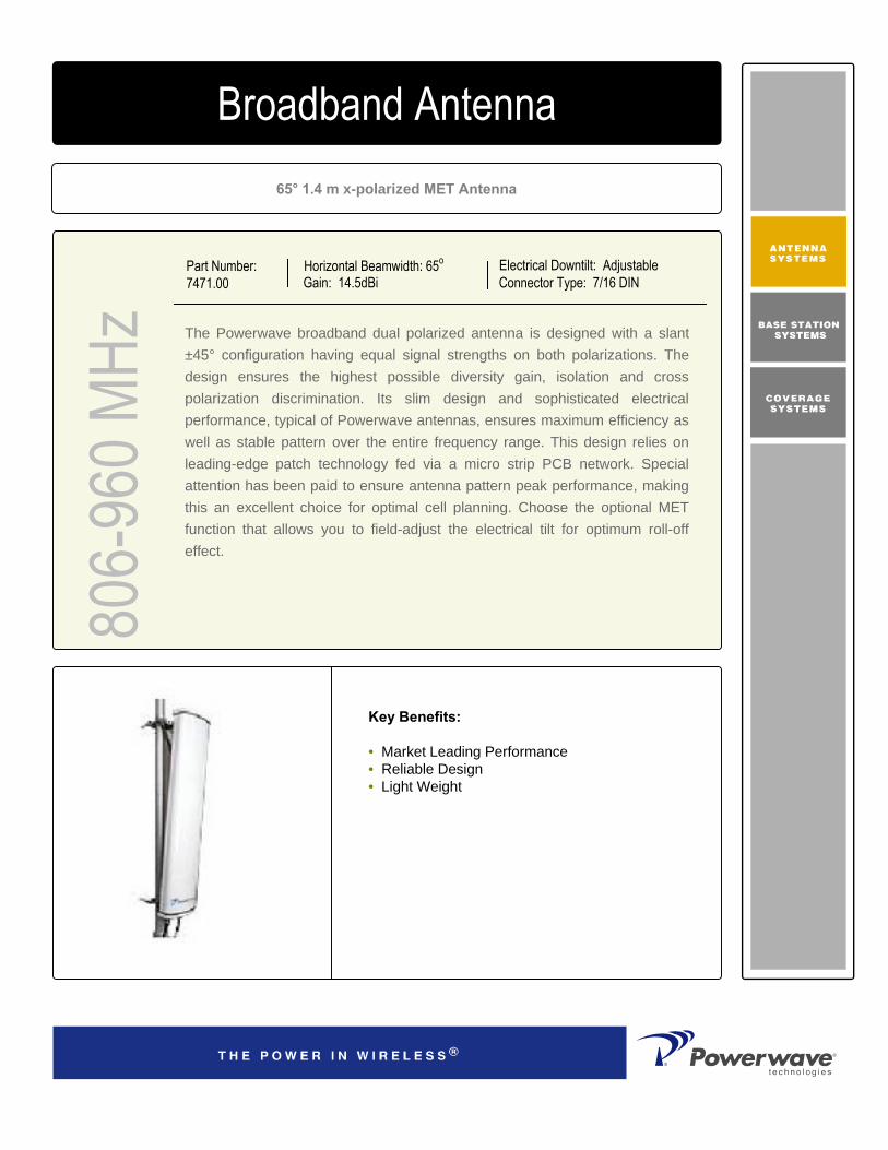
Horizontal Beamwidth: 65o
Gain: 14.5dBiElectrical Downtilt: AdjustableConnector Type: 7/16 DIN
65° 1.4 m x-polarized MET Antenna
Part Number:7471.00
The Powerwave broadband dual polarized antenna is designed with a slant ±45° configuration having equal signal strengths on both polarizations. The design ensures the highest possible diversity gain, isolation and cross polarization discrimination. Its slim design and sophisticated electrical performance, typical of Powerwave antennas, ensures maximum efficiency as well as stable pattern over the entire frequency range. This design relies on leading-edge patch technology fed via a micro strip PCB network. Specialattention has been paid to ensure antenna pattern peak performance, making this an excellent choice for optimal cell planning. Choose the optional MET function that allows you to field-adjust the electrical tilt for optimum roll-off effect.
Broadband Antenna80
6-96
0 MHz
Key Benefits:
• Market Leading Performance• Reliable Design• Light Weight

COVERAGE ANDCAPACITY
TECHNOLOGY LEADERSHIP
NETWORK OPTIMIZATION
QUALITY AND RELIABILITY
D03
1-08
184
Rev
A
Corporate HeadquartersPowerwave Technologies, Inc. 1801 East St. Andrew PlaceSanta Ana, CA 92705 USA
Tel: 714-466-1000Fax: 714-466-5800 www.powerwave.com
Main European OfficeAntennvägen 6SE-187 80 TäbySwedenTel: +46 8 540 822 00Fax: +46 8 540 823 40
©Copyright February 2003, Powerwave Technologies, Inc. All Rights reserved. Powerwave, Powerwave Technologies, The Power in Wireless and the Powerwave logo are registered trademarks of Powerwave Technologies, Inc.
Main Asia Pacific Office23 F Tai Yau Building181 Johnston RoadWanchai, Hong KongTel: +852 2512 6123Fax: +852 2575 4860
15.8 kg (35 lbs) Weight With Brackets
1550x355x255mm (61"x1’2"x10")Packing Size
Light GrayRadome ColorGRPRadome MaterialDC groundedLightning Protection70 m/s (156mph) Survival Wind Speed
435 N (98 lbf)Wind Load, Frontal, 42 m/s Cd=1
1408x280x125mm (4‘9"x11“x5”)Dimensions, HxWxD
BottomConnector Position
7/16 DIN femaleConnector Type
Broadband Antenna
Electrical Specifications
Frequency band (MHz) 806-896 880-960Gain, ± 0.5 (dBi) 14.2 14.7Polarization Dual linear ±45°Nominal Impedance (Ohm) 50VSWR 1.5:1Isolation between inputs, 824-960MHz (dB) 30Horizontal -3 dB beamwidth 70±4° 67±4°Tracking,Horizontal plane, ±60° (dB) <2.0Electrical downtilt range (adjustable) 2° to 12°Vertical -3 dB beamwidth 14.9±1° 13.8±0.8°
Sidelobe suppression, Vertical 1 st upper (dB)
> 19,18,17 > 19,18,17 @2,7,12° MET @2,7,12° MET
Vertical beam squint 1°First null-fill (dB) < -25 < -25Front-to-back ratio (dB) >25 >27Front-to-back ratio, total power (dB) >24 >25Cross-polar discrimination (XPD) ±60° (dB) >10 >10IM3, 2Tx@43dBm (dBc) <-150
Power Handling, Average per input (W) 400 300Power Handling, Average total (W) 800 600
Mechanical Specifications
806-
960 M
Hz
12.18 kg (27 lbs) Weight Without Brackets
19.9 kg (44lbs) Shipping Weight
All specifications are subject to change without notice.Contact your Powerwave representative for complete performance data.

Horizontal Beamwidth: 65o
Gain: 16.5dBiElectrical Downtilt: AdjustableConnector Type: 7/16 female
65° 2.0 m x-polarized MET Antenna
Part Number:7472.00
The Powerwave broadband dual polarized antenna is designed with a slant ±45° configuration having equal signal strengths on both polarizations. The design ensures the highest possible diversity gain, isolation and cross polarization discrimination. Its slim design and sophisticated electrical performance, typical of Powerwave antennas, ensures maximum efficiency as well as stable pattern over the entire frequency range. This design relies on leading-edge patch technology fed via a micro strip PCB network. Specialattention has been paid to ensure antenna pattern peak performance, making this an excellent choice for optimal cell planning. Choose the optional MET function that allows you to field-adjust the electrical tilt for optimum roll-off effect.
Broadband Antenna80
6-96
0 MHz
Key Benefits
• Excellent broad- and multi-band capabilities • Polarization purity makes good diversity gain• Excellent pattern performance and high gain over
frequency• High passive intermodulation performance• Light, slim and robust design

COVERAGE ANDCAPACITY
TECHNOLOGY LEADERSHIP
NETWORK OPTIMIZATION
QUALITY AND RELIABILITY
D03
1-08
185
Rev
A
Corporate HeadquartersPowerwave Technologies, Inc. 1801 East St. Andrew PlaceSanta Ana, CA 92705 USA
Tel: 714-466-1000Fax: 714-466-5800 www.powerwave.com
Main European OfficeAntennvägen 6SE-187 80 TäbySwedenTel: +46 8 540 822 00Fax: +46 8 540 823 40
©Copyright March 2005, Powerwave Technologies, Inc. All Rights reserved. Powerwave, Powerwave Technologies, The Power in Wireless and the Powerwave logo are registered trademarks of Powerwave Technologies, Inc.
Main Asia Pacific Office23 F Tai Yau Building181 Johnston RoadWanchai, Hong KongTel: +852 2512 6123Fax: +852 2575 4860
18 kg (39,7 lbs) Weight With Brackets
2175x355x255mm (7‘2"x1’2"x10")Packing SizeLight GrayRadome ColorGRPRadome MaterialDC groundedLightning Protection70m/s (156mph) Survival Wind Speed
828 N (141 lbf)Wind Load, Frontal, 42 m/s Cd=12033x280x125mm (6‘8"x11“x5”)Dimensions, HxWxDBottomConnector Position
7/16 DIN femaleConnector Type
Broadband Antenna
Electrical Specifications
Frequency band (MHz) 806-896 880-960Gain, ± 0.5 (dBi) 16.0 16.5Polarization Dual linear ±45°
Nominal Impedance (Ohm) 50VSWR , 806-960MHz 1.4:1Isolation between inputs, 806-960MHz (dB) 30Horizontal -3 dB beamwidth 65±5° 65±5°Tracking,Horizontal plane, ±60° (dB) <2.0
Electrical downtilt range (adjustable) 0° to 7.5°Vertical -3 dB beamwidth 9.5±0.6° 9±0.5°Sidelobe suppression, Vertical 1 st upper (dB)
> 20,17,15 > 20,17,15 @0,4,7° MET @0,4,7° MET
Vertical beam squint 0.5°First null-fill (dB) < -18 < -18Front-to-back ratio (dB) >30 >30
Front-to-back ratio, total power (dB) >25 >25
Cross-polar discrimination (XPD) ±60° (dB) >11 >11
IM3, 2Tx@43dBm (dBc) <-150
Power Handling, Average per input (W) 400 300Power Handling, Average total (W) 800 600
Mechanical Specifications
806-
960 M
Hz
All specifications are subject to change without notice. Contact your Powerwave representative for complete performance data.
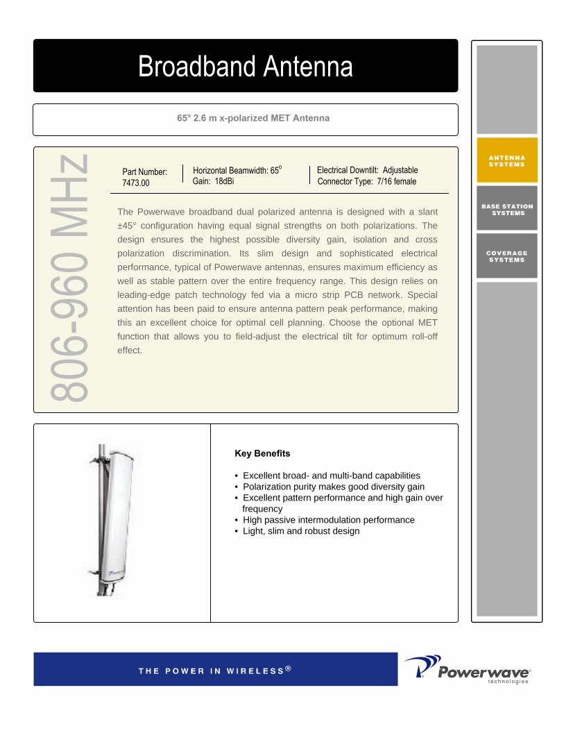
Horizontal Beamwidth: 65o
Gain: 18dBiElectrical Downtilt: AdjustableConnector Type: 7/16 female
65° 2.6 m x-polarized MET Antenna
Part Number:7473.00
The Powerwave broadband dual polarized antenna is designed with a slant ±45° configuration having equal signal strengths on both polarizations. The design ensures the highest possible diversity gain, isolation and cross polarization discrimination. Its slim design and sophisticated electrical performance, typical of Powerwave antennas, ensures maximum efficiency as well as stable pattern over the entire frequency range. This design relies on leading-edge patch technology fed via a micro strip PCB network. Specialattention has been paid to ensure antenna pattern peak performance, making this an excellent choice for optimal cell planning. Choose the optional MET function that allows you to field-adjust the electrical tilt for optimum roll-off effect.
Broadband Antenna80
6-96
0 MHz
Key Benefits
• Excellent broad- and multi-band capabilities • Polarization purity makes good diversity gain• Excellent pattern performance and high gain over
frequency• High passive intermodulation performance• Light, slim and robust design

COVERAGE ANDCAPACITY
TECHNOLOGY LEADERSHIP
NETWORK OPTIMIZATION
QUALITY AND RELIABILITY
D03
1-08
186
Rev
A
Corporate HeadquartersPowerwave Technologies, Inc. 1801 East St. Andrew PlaceSanta Ana, CA 92705 USA
Tel: 714-466-1000Fax: 714-466-5800 www.powerwave.com
Main European OfficeAntennvägen 6SE-187 80 TäbySwedenTel: +46 8 540 822 00Fax: +46 8 540 823 40
©Copyright March 2005, Powerwave Technologies, Inc. All Rights reserved. Powerwave, Powerwave Technologies, The Power in Wireless and the Powerwave logo are registered trademarks of Powerwave Technologies, Inc.
Main Asia Pacific Office23 F Tai Yau Building181 Johnston RoadWanchai, Hong KongTel: +852 2512 6123Fax: +852 2575 4860
21 kg (46.3 lbs) Weight With Brackets
2725x355x255mm (8‘11"x1’2"x10")Packing SizeLight GrayRadome ColorGRPRadome MaterialDC groundedLightning Protection70 (156mph) Survival Wind Speed (m/s)
868 (195 lbf)Wind Load, Frontal, 150 m/s Cd=1 (N)2580x280x125mm (8‘6"x11“x5”)Dimensions, HxWxDBottomConnector Position
7/16 DIN femaleConnector Type
Broadband Antenna
Electrical Specifications
Frequency band (MHz) 806-896 880-960Gain, ± 0.5 (dBi) 17.5 18.0Polarization Dual linear ±45°Nominal Impedance (Ohm) 50VSWR , 806-960MHz 1.4:1Isolation between inputs, 806-960MHz (dB) 30Horizontal -3 dB beamwidth 65±5° 65±5°Tracking,Horizontal plane, ±60° (dB) <2.0
Electrical downtilt range (adjustable) 0° to 5.5°Vertical -3 dB beamwidth 7.3±0.4° 7.0±0.4°Sidelobe suppression, Vertical 1 st upper (dB)
> 20,17,15 > 20,17,15 @0,2,5° MET @0,2,5° MET
Vertical beam squint 0.3°First null-fill (dB) < -18 < -18Front-to-back ratio (dB) >30 >30Front-to-back ratio, total power (dB) >25 >25Cross-polar discrimination (XPD) ±60° (dB) >11 >11IM3, 2Tx@43dBm (dBc) <-150
Power Handling, Average per input (W) 400 300Power Handling, Average total (W) 800 600
All specifications are subject to change without notice. Contact factory for complete performance data.
Mechanical Specifications
806-
960 M
Hz
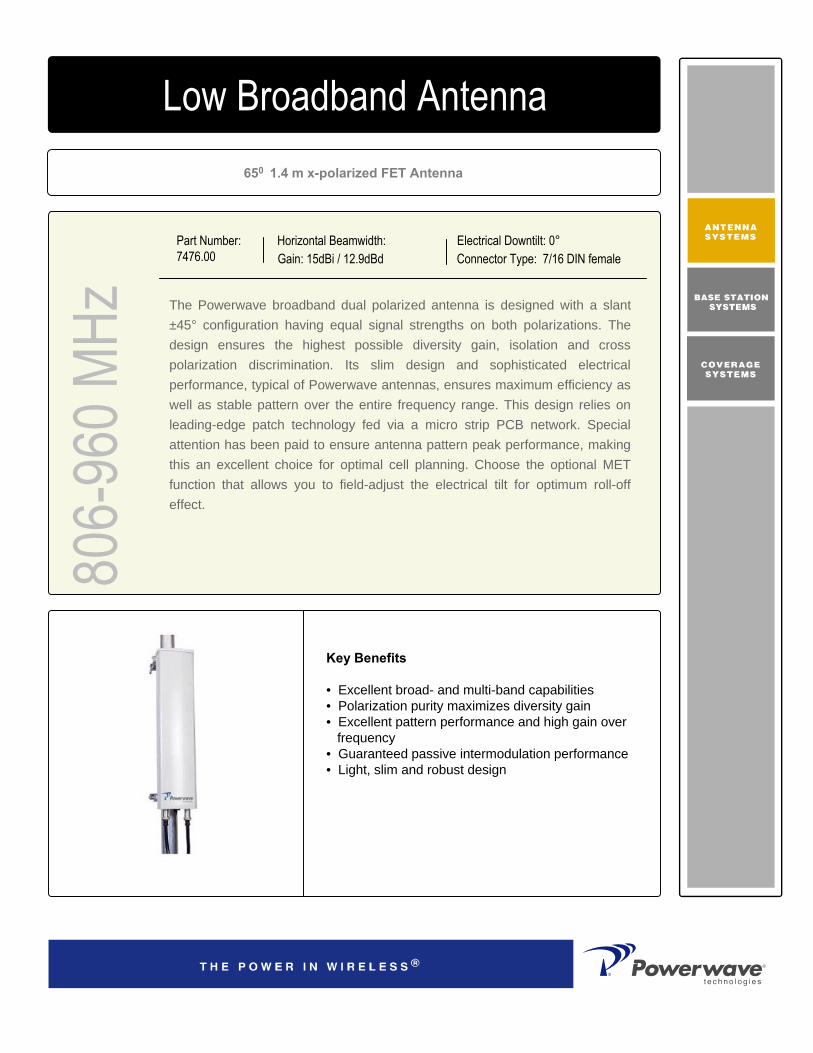
806-
960 M
Hz4168.11.33.00Low Broadband Antenna
Key Benefits
• Excellent broad- and multi-band capabilities • Polarization purity maximizes diversity gain• Excellent pattern performance and high gain over
frequency• Guaranteed passive intermodulation performance• Light, slim and robust design
650 1.4 m x-polarized FET Antenna
The Powerwave broadband dual polarized antenna is designed with a slant ±45° configuration having equal signal strengths on both polarizations. The design ensures the highest possible diversity gain, isolation and cross polarization discrimination. Its slim design and sophisticated electrical performance, typical of Powerwave antennas, ensures maximum efficiency as well as stable pattern over the entire frequency range. This design relies on leading-edge patch technology fed via a micro strip PCB network. Specialattention has been paid to ensure antenna pattern peak performance, making this an excellent choice for optimal cell planning. Choose the optional MET function that allows you to field-adjust the electrical tilt for optimum roll-off effect.
Part Number:7476.00
Horizontal Beamwidth:Gain: 15dBi / 12.9dBd
Electrical Downtilt: 0°Connector Type: 7/16 DIN female

D03
1-08
163
Rev
A
©Copyright September 2003, Powerwave Technologies, Inc. All Rights reserved. Powerwave, Powerwave Technologies, The Power in Wireless and the Powerwave logo are registered trademarks of Powerwave Technologies, Inc.
Corporate HeadquartersPowerwave Technologies, Inc. 1801 East St. Andrew PlaceSanta Ana, CA 92705 USA
Tel: 714-466-1000Fax: 714-466-5800 www.powerwave.com
Main European OfficeAntennvägen 6SE-187 80 TäbySwedenTel: +46 8 540 822 00Fax: +46 8 540 823 40
Main Asia Pacific Office23 F Tai Yau Building181 Johnston RoadWanchai, Hong KongTel: +852 2512 6123Fax: +852 2575 4860
Low Broadband Antenna80
6-96
0 MHz
Mechanical Specifications
Typical Horizontal and Vertical 7476.00 Patterns
Electrical SpecificationsFrequency band (MHz) 806-896 880-960Gain, ± 0.5 (dBi) / (dBd) 14.7/12.6 15.0/12.9Polarization Dual slant ±45°Nominal Impedance (Ohm) 50VSWR 1.4:1Isolation between inputs, 824-960MHz (dB) 30Horizontal -3 dB beamwidth 66±4° 64±4°Tracking,Horizontal plane, ±60° (dB) <1.0Electrical downtilt 0°Vertical -3 dB beamwidth 14.9±1° 13.8±0.8°Sidelobe suppression, Vertical 1 st upper (dB)
> 19 > 19
Vertical beam squint 1°First null-fill (dB) < -25 < -25Front-to-back ratio (dB) >30 >30Front-to-back ratio, total power (dB) >25 >25Cross-polar discrimination (XPD) ±60° (dB) >12 >12IM3, @2x43dBm (dBc) <-150Power Handling, Average per input (W) 400 300Power Handling, Average total (W) 800 600
15 kg (33 lbs)Shipping Weight1490x355x200mm (4'11"x1'2"x8")Packing Size
Light GrayRadome Color
GRPRadome Material
DC groundedLightning Protection
70m/s (156 mph)Survival Wind Speed
401 N (90 lbf)Wind Load, Frontal, 42 m/s Cd=1
14 kg (31 lbs)Weight with Brackets
1300x280x125mm (4'3"x11"x5")Dimensions, HxWxD
BottomConnector Position
2 x 7/16 DIN femaleConnector Type
Mounting Pre-mounted standard brackets
All specifications are subject to change without notice.Contact your Powerwave representative for complete performance data.

806-
960 M
Hz4168.11.33.00Low Broadband Antenna
Key Benefits
• Excellent broad- and multi-band capabilities • Polarization purity maximizes diversity gain• Excellent pattern performance and high gain over
frequency• Guaranteed passive intermodulation performance• Light, slim and robust design
650 1.4 m x-polarized FET Antenna
The Powerwave broadband dual polarized antenna is designed with a slant ±45° configuration having equal signal strengths on both polarizations. The design ensures the highest possible diversity gain, isolation and cross polarization discrimination. Its slim design and sophisticated electrical performance, typical of Powerwave antennas, ensures maximum efficiency as well as stable pattern over the entire frequency range. This design relies on leading-edge patch technology fed via a micro strip PCB network. Specialattention has been paid to ensure antenna pattern peak performance, making this an excellent choice for optimal cell planning. Choose the optional MET function that allows you to field-adjust the electrical tilt for optimum roll-off effect.
Part Number:7476.02
Horizontal Beamwidth:Gain: 15dBi / 12.9dBd
Electrical Downtilt: 2°Connector Type: 7/16 DIN female

D03
1-08
164
Rev
A
©Copyright September 2003, Powerwave Technologies, Inc. All Rights reserved. Powerwave, Powerwave Technologies, The Power in Wireless and the Powerwave logo are registered trademarks of Powerwave Technologies, Inc.
Corporate HeadquartersPowerwave Technologies, Inc. 1801 East St. Andrew PlaceSanta Ana, CA 92705 USA
Tel: 714-466-1000Fax: 714-466-5800 www.powerwave.com
Main European OfficeAntennvägen 6SE-187 80 TäbySwedenTel: +46 8 540 822 00Fax: +46 8 540 823 40
Main Asia Pacific Office23 F Tai Yau Building181 Johnston RoadWanchai, Hong KongTel: +852 2512 6123Fax: +852 2575 4860
Low Broadband Antenna80
6-96
0 MHz
Mechanical Specifications
Typical Horizontal and Vertical 7476.02 Patterns
Electrical SpecificationsFrequency band (MHz) 806-896 880-960Gain, ± 0.5 (dBi) / (dBd) 14.7/12.6 15.0/12.9Polarization Dual slant ±45°Nominal Impedance (Ohm) 50VSWR 1.4:1Isolation between inputs, 824-960MHz (dB) 30Horizontal -3 dB beamwidth 66±4° 64±4°Tracking,Horizontal plane, ±60° (dB) <1.0Electrical downtilt 2°Vertical -3 dB beamwidth 14.9±1° 13.8±0.8°Sidelobe suppression, Vertical 1 st upper (dB)
> 19, > 19
Vertical beam squint 1°First null-fill (dB) < -25 < -25Front-to-back ratio (dB) >30 >30Front-to-back ratio, total power (dB) >25 >25Cross-polar discrimination (XPD) ±60° (dB) >12 >12IM3, @2x43dBm (dBc) <-150
Power Handling, Average per input (W) 400 300Power Handling, Average total (W) 800 600
15 kg (33 lbs)Shipping Weight1490x355x200mm (4'11"x1'2"x8")Packing Size
Light GrayRadome Color
GRPRadome Material
DC groundedLightning Protection
70m/s (156 mph)Survival Wind Speed
401N (90 lbf)Wind Load, Frontal, 42 m/s Cd=1
14 kg (31 lbs)Weight with Brackets
1300x280x125mm (4'3"x11"x5")Dimensions, HxWxD
BottomConnector Position
2 x 7/16 DIN femaleConnector Type
Mounting Pre-mounted standard brackets
All specifications are subject to change without notice.Contact your Powerwave representative for complete performance data.
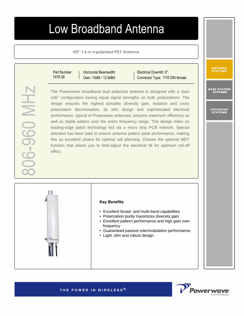
806-
960 M
Hz4168.11.33.00Low Broadband Antenna
Key Benefits
• Excellent broad- and multi-band capabilities • Polarization purity maximizes diversity gain• Excellent pattern performance and high gain over
frequency• Guaranteed passive intermodulation performance• Light, slim and robust design
650 1.4 m x-polarized FET Antenna
The Powerwave broadband dual polarized antenna is designed with a slant ±45° configuration having equal signal strengths on both polarizations. The design ensures the highest possible diversity gain, isolation and cross polarization discrimination. Its slim design and sophisticated electrical performance, typical of Powerwave antennas, ensures maximum efficiency as well as stable pattern over the entire frequency range. This design relies on leading-edge patch technology fed via a micro strip PCB network. Specialattention has been paid to ensure antenna pattern peak performance, making this an excellent choice for optimal cell planning. Choose the optional MET function that allows you to field-adjust the electrical tilt for optimum roll-off effect.
Part Number:7476.06
Horizontal Beamwidth:Gain: 15dBi / 12.9dBd
Electrical Downtilt: 6°Connector Type: 7/16 DIN female

D03
1-08
165
Rev
A
©Copyright September 2003, Powerwave Technologies, Inc. All Rights reserved. Powerwave, Powerwave Technologies, The Power in Wireless and the Powerwave logo are registered trademarks of Powerwave Technologies, Inc.
Corporate HeadquartersPowerwave Technologies, Inc. 1801 East St. Andrew PlaceSanta Ana, CA 92705 USA
Tel: 714-466-1000Fax: 714-466-5800 www.powerwave.com
Main European OfficeAntennvägen 6SE-187 80 TäbySwedenTel: +46 8 540 822 00Fax: +46 8 540 823 40
Main Asia Pacific Office23 F Tai Yau Building181 Johnston RoadWanchai, Hong KongTel: +852 2512 6123Fax: +852 2575 4860
Low Broadband Antenna80
6-96
0 MHz
Mechanical Specifications
Typical Horizontal and Vertical 7476.06 Patterns
Electrical SpecificationsFrequency band (MHz) 806-896 880-960Gain, ± 0.5 (dBi) / (dBd) 14.7/12.6 15.0/12.9Polarization Dual slant ±45°Nominal Impedance (Ohm) 50VSWR 1.4:1Isolation between inputs, 824-960MHz (dB) 30Horizontal -3 dB beamwidth 66±4° 64±4°Tracking,Horizontal plane, ±60° (dB) <1.0Electrical downtilt 6°Vertical -3 dB beamwidth 14.9±1° 13.8±0.8°
Sidelobe suppression, Vertical 1 st upper (dB)
> 19, > 19
Vertical beam squint 1°First null-fill (dB) < -25 < -25Front-to-back ratio (dB) >30 >30Front-to-back ratio, total power (dB) >25 >25Cross-polar discrimination (XPD) ±60° (dB) >12 >12IM3, @2x43dBm (dBc) <-150
Power Handling, Average per input (W) 400 300Power Handling, Average total (W) 800 600
15 kg (33 lbs)Shipping Weight
1490x355x200mm (4'11"x1'2"x8")Packing Size
Light GrayRadome Color
GRPRadome Material
DC groundedLightning Protection
70m/s (156 mph)Survival Wind Speed
401N (90 lbf)Wind Load, Frontal, 42 m/s Cd=1
14 kg (31 lbs)Weight with Brackets
1300x280x125mm (4'3"x11"x5")Dimensions, HxWxD
BottomConnector Position
2 x 7/16 DIN femaleConnector Type
Mounting Pre-mounted standard brackets
All specifications are subject to change without notice.Contact your Powerwave representative for complete performance data.

806-
960 M
Hz4168.11.33.00Low Broadband Antenna
Key Benefits
• Excellent broad- and multi-band capabilities • Polarization purity maximizes diversity gain• Excellent pattern performance and high gain over
frequency• Guaranteed passive intermodulation performance• Light, slim and robust design
650 2.0 m x-polarized FET Antenna
The Powerwave broadband dual polarized antenna is designed with a slant ±45° configuration having equal signal strengths on both polarizations. The design ensures the highest possible diversity gain, isolation and cross polarization discrimination. Its slim design and sophisticated electrical performance, typical of Powerwave antennas, ensures maximum efficiency as well as stable pattern over the entire frequency range. This design relies on leading-edge patch technology fed via a micro strip PCB network. Specialattention has been paid to ensure antenna pattern peak performance, making this an excellent choice for optimal cell planning. Choose the optional MET function that allows you to field-adjust the electrical tilt for optimum roll-off effect.
Part Number:7477.00
Horizontal Beamwidth:Gain: 16.5dBi / 14.4dBd
Electrical Downtilt: 0°Connector Type: 7/16 DIN female

D03
1-08
166
Rev
A
©Copyright September 2003, Powerwave Technologies, Inc. All Rights reserved. Powerwave, Powerwave Technologies, The Power in Wireless and the Powerwave logo are registered trademarks of Powerwave Technologies, Inc.
Corporate HeadquartersPowerwave Technologies, Inc. 1801 East St. Andrew PlaceSanta Ana, CA 92705 USA
Tel: 714-466-1000Fax: 714-466-5800 www.powerwave.com
Main European OfficeAntennvägen 6SE-187 80 TäbySwedenTel: +46 8 540 822 00Fax: +46 8 540 823 40
Main Asia Pacific Office23 F Tai Yau Building181 Johnston RoadWanchai, Hong KongTel: +852 2512 6123Fax: +852 2575 4860
Low Broadband Antenna80
6-96
0 MHz
Mechanical Specifications
Typical Horizontal and Vertical 7477.00 Patterns
Electrical SpecificationsFrequency band (MHz) 806-896 880-960Gain, ± 0.5 (dBi) / (dBd) 16.0/13.9 16.5/14.4Polarization Dual slant ±45°Nominal Impedance (Ohm) 50VSWR 1.4:1Isolation between inputs, 824-960MHz (dB) 30Horizontal -3 dB beamwidth 66±4° 64±4°Tracking,Horizontal plane, ±60° (dB) <1.0Electrical downtilt 0°Vertical -3 dB beamwidth 9.5±0.6° 9±0.5°Sidelobe suppression, Vertical 1 st upper (dB)
> 20, > 20
Vertical beam squint 0.5°First null-fill (dB) < -18 < -18Front-to-back ratio (dB) >30 >30Front-to-back ratio, total power (dB) >25 >25Cross-polar discrimination (XPD) ±60° (dB) >12 >12IM3, @2x43dBm (dBc) <-150Power Handling, Average per input (W) 400 300Power Handling, Average total (W) 800 600
Packing Size
Light GrayRadome Color
GRPRadome Material
DC groundedLightning Protection
70m/s (156 mph)Survival Wind Speed
628 N (141 lbf)Wind Load, Frontal, 42 m/s Cd=1
18 kg (39,7 lbs) Weight with Brackets
2033x280x125mm (6‘8"x11“x5”)Dimensions, HxWxD
BottomConnector Position
2 x 7/16 DIN femaleConnector Type
Mounting Pre-mounted standard brackets
2175x355x255mm (7‘2"x1’2"x10")
All specifications are subject to change without notice.Contact your Powerwave representative for complete performance data.

806-
960 M
Hz4168.11.33.00Low Broadband Antenna
Key Benefits
• Excellent broad- and multi-band capabilities • Polarization purity maximizes diversity gain• Excellent pattern performance and high gain over
frequency• Guaranteed passive intermodulation performance• Light, slim and robust design
650 2.0 m x-polarized FET Antenna
The Powerwave broadband dual polarized antenna is designed with a slant ±45° configuration having equal signal strengths on both polarizations. The design ensures the highest possible diversity gain, isolation and cross polarization discrimination. Its slim design and sophisticated electrical performance, typical of Powerwave antennas, ensures maximum efficiency as well as stable pattern over the entire frequency range. This design relies on leading-edge patch technology fed via a micro strip PCB network. Specialattention has been paid to ensure antenna pattern peak performance, making this an excellent choice for optimal cell planning. Choose the optional MET function that allows you to field-adjust the electrical tilt for optimum roll-off effect.
Part Number:7477.02 Gain: 16.5dBi / 14.4dBd
Horizontal Beamwidth: Electrical Downtilt: 2°Connector Type: 7/16 DIN female

D03
1-08
167
Rev
A
©Copyright September 2003, Powerwave Technologies, Inc. All Rights reserved. Powerwave, Powerwave Technologies, The Power in Wireless and the Powerwave logo are registered trademarks of Powerwave Technologies, Inc.
Corporate HeadquartersPowerwave Technologies, Inc. 1801 East St. Andrew PlaceSanta Ana, CA 92705 USA
Tel: 714-466-1000Fax: 714-466-5800 www.powerwave.com
Main European OfficeAntennvägen 6SE-187 80 TäbySwedenTel: +46 8 540 822 00Fax: +46 8 540 823 40
Main Asia pacific Office23 F Tai Yau Building181 Johnston RoadWanchai, Hong KongTel: +852 2512 6123Fax: +852 2575 4860
Low Broadband Antenna80
6-96
0 MHz
Mechanical Specifications
Typical Horizontal and Vertical 7477.02 Patterns
Electrical SpecificationsFrequency band (MHz) 806-896 880-960Gain, ± 0.5 (dBi) / (dBd) 16.0/13.9 16.5/14.4Polarization Dual slant ±45°Nominal Impedance (Ohm) 50VSWR 1.4:1Isolation between inputs, 824-960MHz (dB) 30Horizontal -3 dB beamwidth 66±4° 64±4°Tracking,Horizontal plane, ±60° (dB) <2.0Electrical downtilt 2°Vertical -3 dB beamwidth 9.5±0.6° 9±0.5°Sidelobe suppression, Vertical 1 st upper (dB)
> 20, > 20
Vertical beam squint 0.5°First null-fill (dB) < -18 < -18Front-to-back ratio (dB) >30 >30Front-to-back ratio, total power (dB) >25 >25Cross-polar discrimination (XPD) ±60° (dB) >12 >12IM3, @2x43dBm (dBc) <-150Power Handling, Average per input (W) 400 300Power Handling, Average total (W) 800 600
Packing Size
Light GrayRadome Color
GRPRadome Material
DC groundedLightning Protection
70m/s (156 mph)Survival Wind Speed
628N (141 lbf)Wind Load, Frontal, 42 m/s Cd=1
18 kg (39,7 lbs) Weight with Brackets
2033x280x125mm (6‘8"x11“x5”)Dimensions, HxWxD
BottomConnector Position
2 x 7/16 DIN femaleConnector Type
Mounting Pre-mounted standard brackets
2175x355x255mm (7‘2"x1’2"x10")
All specifications are subject to change without notice.Contact your Powerwave representative for complete performance data.

806-
960 M
Hz4168.11.33.00Low Broadband Antenna
Key Benefits
• Excellent broad- and multi-band capabilities • Polarization purity maximizes diversity gain• Excellent pattern performance and high gain over
frequency• Guaranteed passive intermodulation performance• Light, slim and robust design
650 2.0 m x-polarized FET Antenna
The Powerwave broadband dual polarized antenna is designed with a slant ±45° configuration having equal signal strengths on both polarizations. The design ensures the highest possible diversity gain, isolation and cross polarization discrimination. Its slim design and sophisticated electrical performance, typical of Powerwave antennas, ensures maximum efficiency as well as stable pattern over the entire frequency range. This design relies on leading-edge patch technology fed via a micro strip PCB network. Specialattention has been paid to ensure antenna pattern peak performance, making this an excellent choice for optimal cell planning. Choose the optional MET function that allows you to field-adjust the electrical tilt for optimum roll-off effect.
Part Number:7477.06
Horizontal Beamwidth:Gain: 16.5dBi / 14.4dBd
Electrical Downtilt: 6°Connector Type: 7/16 DIN female
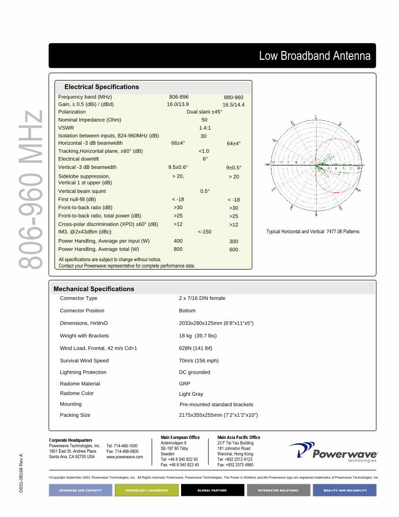
D03
1-08
168
Rev
A
©Copyright September 2003, Powerwave Technologies, Inc. All Rights reserved. Powerwave, Powerwave Technologies, The Power in Wireless and the Powerwave logo are registered trademarks of Powerwave Technologies, Inc.
Corporate HeadquartersPowerwave Technologies, Inc. 1801 East St. Andrew PlaceSanta Ana, CA 92705 USA
Tel: 714-466-1000Fax: 714-466-5800 www.powerwave.com
Main European OfficeAntennvägen 6SE-187 80 TäbySwedenTel: +46 8 540 822 00Fax: +46 8 540 823 40
Main Asia Pacific Office23 F Tai Yau Building181 Johnston RoadWanchai, Hong KongTel: +852 2512 6123Fax: +852 2575 4860
Low Broadband Antenna80
6-96
0 MHz
Mechanical Specifications
Typical Horizontal and Vertical 7477.06 Patterns
Electrical SpecificationsFrequency band (MHz) 806-896 880-960Gain, ± 0.5 (dBi) / (dBd) 16.0/13.9 16.5/14.4Polarization Dual slant ±45°Nominal Impedance (Ohm) 50VSWR 1.4:1Isolation between inputs, 824-960MHz (dB) 30Horizontal -3 dB beamwidth 66±4° 64±4°Tracking,Horizontal plane, ±60° (dB) <1.0Electrical downtilt 6°Vertical -3 dB beamwidth 9.5±0.6° 9±0.5°Sidelobe suppression, Vertical 1 st upper (dB)
> 20, > 20
Vertical beam squint 0.5°First null-fill (dB) < -18 < -18Front-to-back ratio (dB) >30 >30Front-to-back ratio, total power (dB) >25 >25Cross-polar discrimination (XPD) ±60° (dB) >12 >12IM3, @2x43dBm (dBc) <-150
Power Handling, Average per input (W) 400 300Power Handling, Average total (W) 800 600
Packing Size
Light GrayRadome Color
GRPRadome Material
DC groundedLightning Protection
70m/s (156 mph)Survival Wind Speed
628N (141 lbf)Wind Load, Frontal, 42 m/s Cd=1
18 kg (39,7 lbs) Weight with Brackets
2033x280x125mm (6‘8"x11“x5”)Dimensions, HxWxD
BottomConnector Position
2 x 7/16 DIN femaleConnector Type
Mounting Pre-mounted standard brackets
2175x355x255mm (7‘2"x1’2"x10")
All specifications are subject to change without notice.Contact your Powerwave representative for complete performance data.

806-
960 M
Hz4168.11.33.00Low Broadband Antenna
Key Benefits
• Excellent broad- and multi-band capabilities • Polarization purity maximizes diversity gain• Excellent pattern performance and high gain over
frequency• Guaranteed passive intermodulation performance• Light, slim and robust design
650 2.6 m x-polarized FET Antenna
The Powerwave broadband dual polarized antenna is designed with a slant ±45° configuration having equal signal strengths on both polarizations. The design ensures the highest possible diversity gain, isolation and cross polarization discrimination. Its slim design and sophisticated electrical performance, typical of Powerwave antennas, ensures maximum efficiency as well as stable pattern over the entire frequency range. This design relies on leading-edge patch technology fed via a micro strip PCB network. Specialattention has been paid to ensure antenna pattern peak performance, making this an excellent choice for optimal cell planning. Choose the optional MET function that allows you to field-adjust the electrical tilt for optimum roll-off effect.
Part Number:7478.00
Horizontal Beamwidth:Gain: 18dBi / 15.9dBd
Electrical Downtilt: 0°Connector Type: 7/16 DIN female

D03
1-08
169
Rev
A
©Copyright September 2003, Powerwave Technologies, Inc. All Rights reserved. Powerwave, Powerwave Technologies, The Power in Wireless and the Powerwave logo are registered trademarks of Powerwave Technologies, Inc.
Corporate HeadquartersPowerwave Technologies, Inc. 1801 East St. Andrew PlaceSanta Ana, CA 92705 USA
Tel: 714-466-1000Fax: 714-466-5800 www.powerwave.com
Main European OfficeAntennvägen 6SE-187 80 TäbySwedenTel: +46 8 540 822 00Fax: +46 8 540 823 40
Main Asia Pacific Office23 F Tai Yau Building181 Johnston RoadWanchai, Hong KongTel: +852 2512 6123Fax: +852 2575 4860
Low Broadband Antenna80
6-96
0 MHz
Mechanical Specifications
Typical Horizontal and Vertical 7478.00 Patterns
Electrical SpecificationsFrequency band (MHz) 806-896 880-960Gain, ± 0.5 (dBi) / (dBd) 17.5/15.4 18/15.9Polarization Dual slant ±45°Nominal Impedance (Ohm) 50VSWR 1.4:1Isolation between inputs, 824-960MHz (dB) 30Horizontal -3 dB beamwidth 66±4° 64±4°Tracking,Horizontal plane, ±60° (dB) <1.0Electrical downtilt 0°Vertical -3 dB beamwidth 7.3±0.4° 7.0±0.4°Sidelobe suppression, Vertical 1 st upper (dB)
> 20, > 20
Vertical beam squint 0.3°First null-fill (dB) < -18 < -18Front-to-back ratio (dB) >30 >30Front-to-back ratio, total power (dB) >25 >25Cross-polar discrimination (XPD) ±60° (dB) >12 >12IM3, @2x43dBm (dBc) <-150
Power Handling, Average per input (W) 400 300Power Handling, Average total (W) 800 600
Packing Size
Light GrayRadome Color
GRPRadome Material
DC groundedLightning Protection
70m/s (156 mph)Survival Wind Speed
796N (179 lbf)Wind Load, Frontal, 42 m/s Cd=1
21 kg (46.3 lbs)Weight with Brackets
2580x280x125mm (8‘6"x11“x5”)Dimensions, HxWxD
BottomConnector Position
2 x 7/16 DIN femaleConnector Type
Mounting Pre-mounted standard brackets
2725x355x255mm (8‘11"x1’2"x10")
All specifications are subject to change without notice.Contact your Powerwave representative for complete performance data.

806-
960 M
Hz4168.11.33.00Low Broadband Antenna
Key Benefits
• Excellent broad- and multi-band capabilities • Polarization purity maximizes diversity gain• Excellent pattern performance and high gain over
frequency• Guaranteed passive intermodulation performance• Light, slim and robust design
650 2.6 m x-polarized FET Antenna
The Powerwave broadband dual polarized antenna is designed with a slant ±45° configuration having equal signal strengths on both polarizations. The design ensures the highest possible diversity gain, isolation and cross polarization discrimination. Its slim design and sophisticated electrical performance, typical of Powerwave antennas, ensures maximum efficiency as well as stable pattern over the entire frequency range. This design relies on leading-edge patch technology fed via a micro strip PCB network. Specialattention has been paid to ensure antenna pattern peak performance, making this an excellent choice for optimal cell planning. Choose the optional MET function that allows you to field-adjust the electrical tilt for optimum roll-off effect.
Part Number:7478.02
Horizontal Beamwidth:Gain: 18dBi / 15.9dBd
Electrical Downtilt: 2°Connector Type: 7/16 DIN female

D03
1-08
170
Rev
A
©Copyright September 2003, Powerwave Technologies, Inc. All Rights reserved. Powerwave, Powerwave Technologies, The Power in Wireless and the Powerwave logo are registered trademarks of Powerwave Technologies, Inc.
Corporate HeadquartersPowerwave Technologies, Inc. 1801 East St. Andrew PlaceSanta Ana, CA 92705 USA
Tel: 714-466-1000Fax: 714-466-5800 www.powerwave.com
Main European OfficeAntennvägen 6SE-187 80 TäbySwedenTel: +46 8 540 822 00Fax: +46 8 540 823 40
Main Asia Pacific Office23 F Tai Yau Building181 Johnston RoadWanchai, Hong KongTel: +852 2512 6123Fax: +852 2575 4860
Low Broadband Antenna80
6-96
0 MHz
Mechanical Specifications
Typical Horizontal and Vertical 7478.02 Patterns
Electrical SpecificationsFrequency band (MHz) 806-896 880-960Gain, ± 0.5 (dBi) / (dBd) 17.5/15.4 18/15.9Polarization Dual slant ±45°Nominal Impedance (Ohm) 50VSWR 1.4:1Isolation between inputs, 824-960MHz (dB) 30Horizontal -3 dB beamwidth 66±4° 64±4°Tracking,Horizontal plane, ±60° (dB) <1.0Electrical downtilt 2°Vertical -3 dB beamwidth 7.3±0.4° 7.0±0.4°Sidelobe suppression, Vertical 1 st upper (dB)
> 20, > 20
Vertical beam squint 0.3°First null-fill (dB) < -18 < -18Front-to-back ratio (dB) >30 >30Front-to-back ratio, total power (dB) >25 >25Cross-polar discrimination (XPD) ±60° (dB) >12 >12IM3, @2x43dBm (dBc) <-150
Power Handling, Average per input (W) 400 300Power Handling, Average total (W) 800 600
Packing Size
Light GrayRadome Color
GRPRadome Material
DC groundedLightning Protection
70m/s (156 mph)Survival Wind Speed
796N (179 lbf)Wind Load, Frontal, 42 m/s Cd=1
21 kg (46.3 lbs)Weight with Brackets
2580x280x125mm (8‘6"x11“x5”)Dimensions, HxWxD
BottomConnector Position
2 x 7/16 DIN femaleConnector Type
Mounting Pre-mounted standard brackets
2725x355x255mm (8‘11"x1’2"x10")
All specifications are subject to change without notice.Contact your Powerwave representative for complete performance data.

806-
960 M
Hz4168.11.33.00Low Broadband Antenna
Key Benefits
• Excellent broad- and multi-band capabilities • Polarization purity maximizes diversity gain• Excellent pattern performance and high gain over
frequency• Guaranteed passive intermodulation performance• Light, slim and robust design
650 2.6 m x-polarized FET Antenna
The Powerwave broadband dual polarized antenna is designed with a slant ±45° configuration having equal signal strengths on both polarizations. The design ensures the highest possible diversity gain, isolation and cross polarization discrimination. Its slim design and sophisticated electrical performance, typical of Powerwave antennas, ensures maximum efficiency as well as stable pattern over the entire frequency range. This design relies on leading-edge patch technology fed via a micro strip PCB network. Specialattention has been paid to ensure antenna pattern peak performance, making this an excellent choice for optimal cell planning. Choose the optional MET function that allows you to field-adjust the electrical tilt for optimum roll-off effect.
Part Number:7478.06
Horizontal Beamwidth:Gain: 18dBi / 15.9dBd
Electrical Downtilt: 6°Connector Type: 7/16 DIN female

D03
1-08
171
Rev
A
©Copyright September 2003, Powerwave Technologies, Inc. All Rights reserved. Powerwave, Powerwave Technologies, The Power in Wireless and the Powerwave logo are registered trademarks of Powerwave Technologies, Inc.
Corporate HeadquartersPowerwave Technologies, Inc. 1801 East St. Andrew PlaceSanta Ana, CA 92705 USA
Tel: 714-466-1000Fax: 714-466-5800 www.powerwave.com
Main European OfficeAntennvägen 6SE-187 80 TäbySwedenTel: +46 8 540 822 00Fax: +46 8 540 823 40
Main Asia Pacific Office23 F Tai Yau Building181 Johnston RoadWanchai, Hong KongTel: +852 2512 6123Fax: +852 2575 4860
Low Broadband Antenna80
6-96
0 MHz
Mechanical Specifications
Typical Horizontal and Vertical 7478.06 Patterns
Electrical Specifications
All specifications are subject to change without notice. Contact factory for complete performance data.
Frequency band (MHz) 806-896 880-960Gain, ± 0.5 (dBi) / (dBd) 17.5/15.4 18/15.9Polarization Dual slant ±45°Nominal Impedance (Ohm) 50VSWR 1.4:1Isolation between inputs, 824-960MHz (dB) 30Horizontal -3 dB beamwidth 66±4° 64±4°Tracking,Horizontal plane, ±60° (dB) <1.0Electrical downtilt 6°Vertical -3 dB beamwidth 7.3±0.4° 7.0±0.4°Sidelobe suppression, Vertical 1 st upper (dB)
> 20, > 20
Vertical beam squint 0.3°First null-fill (dB) < -18 < -18Front-to-back ratio (dB) >30 >30Front-to-back ratio, total power (dB) >25 >25Cross-polar discrimination (XPD) ±60° (dB) >12 >12IM3, @2x43dBm (dBc) <-150
Power Handling, Average per input (W) 400 300Power Handling, Average total (W) 800 600
Packing Size
Light GrayRadome Color
GRPRadome Material
DC groundedLightning Protection
70m/s (156 mph)Survival Wind Speed
796N (179 lbf)Wind Load, Frontal, 42 m/s Cd=1
21 kg (46.3 lbs)Weight with Brackets
2580x280x125mm (8‘6"x11“x5”)Dimensions, HxWxD
BottomConnector Position
2 x 7/16 DIN femaleConnector Type
Mounting Pre-mounted standard brackets
2725x355x255mm (8‘11"x1’2"x10")

806 –
960 M
Hz
Horizontal Beamwidth: 90°
Gain: 13.5 dBiElectrical Downtilt: AdjustableConnector Type: 7/16 DIN female
90° 1.3 m x-polarized MET Antenna
Part Number:7481.00
The Powerwave broadband dual polarized antenna is designed with a slant ±45° configuration having equal signal strengths on both polarizations. The design ensures the highest possible diversity gain, isolation and cross polarization discrimination. Its slim design and sophisticated electrical performance, typical of Powerwave antennas, ensures maximum efficiency as well as stable pattern over the entire frequency range. This design relies on leading-edge patch technology fed via a micro strip PCB network. Special attention has been paid to ensure antenna pattern peak performance, making this an excellent choice for optimal cell planning. Choose the optional MET function that allows you to field-adjust the electrical tilt from 0° to the first null at horizon (16°) for optimum roll-off effect.
Broadband Antenna
Key Benefits
• Excellent broad- and multi-band capabilities • Polarization purity makes good diversity gain• Excellent pattern performance and high gain over
frequency• High passive intermodulation performance• Light, slim and robust design
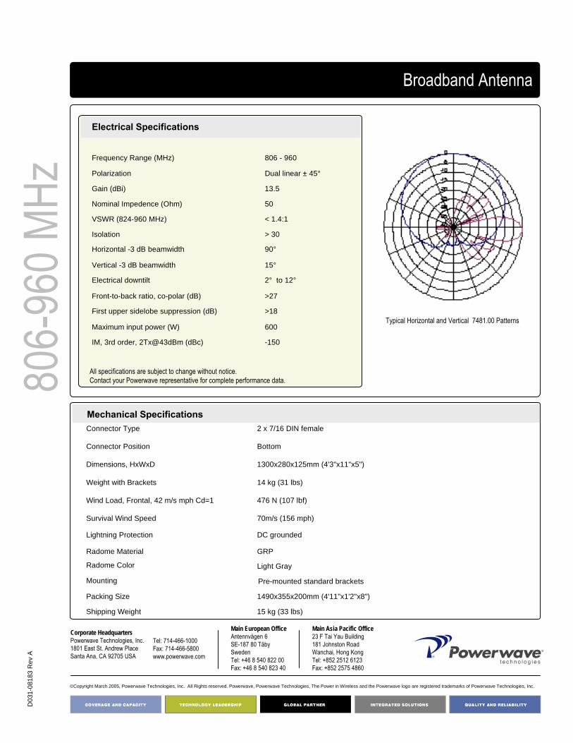
D03
1-08
183
Rev
A
Corporate HeadquartersPowerwave Technologies, Inc. 1801 East St. Andrew PlaceSanta Ana, CA 92705 USA
Tel: 714-466-1000Fax: 714-466-5800 www.powerwave.com
Main European OfficeAntennvägen 6SE-187 80 TäbySwedenTel: +46 8 540 822 00Fax: +46 8 540 823 40
©Copyright March 2005, Powerwave Technologies, Inc. All Rights reserved. Powerwave, Powerwave Technologies, The Power in Wireless and the Powerwave logo are registered trademarks of Powerwave Technologies, Inc.
Main Asia Pacific Office23 F Tai Yau Building181 Johnston RoadWanchai, Hong KongTel: +852 2512 6123Fax: +852 2575 4860
806-
960 M
HzBroadband Antenna
-150IM, 3rd order, 2Tx@43dBm (dBc)
600 Maximum input power (W)
>18First upper sidelobe suppression (dB)
>27Front-to-back ratio, co-polar (dB)
2° to 12°Electrical downtilt
15°Vertical -3 dB beamwidth
90°Horizontal -3 dB beamwidth
> 30Isolation
< 1.4:1VSWR (824-960 MHz)
50Nominal Impedence (Ohm)
13.5Gain (dBi)
Dual linear ± 45°Polarization
806 - 960Frequency Range (MHz)
Electrical Specifications
15 kg (33 lbs)Shipping Weight
1490x355x200mm (4'11"x1'2"x8")Packing Size
Light GrayRadome Color
GRPRadome Material
DC groundedLightning Protection
70m/s (156 mph)Survival Wind Speed
476 N (107 lbf)Wind Load, Frontal, 42 m/s mph Cd=1
14 kg (31 lbs)Weight with Brackets
1300x280x125mm (4'3"x11"x5")Dimensions, HxWxD
BottomConnector Position
2 x 7/16 DIN femaleConnector Type
Mechanical Specifications
Mounting Pre-mounted standard brackets
Typical Horizontal and Vertical 7481.00 Patterns
All specifications are subject to change without notice.Contact your Powerwave representative for complete performance data.

806 –
960 M
Hz Horizontal Beamwidth: 90o
Gain: 15dBiElectrical Downtilt: AdjustableConnector Type: 7/16 DIN female
90° 2.0 m x-polarized MET Antenna
Part Number:7482.00
The Powerwave broadband dual polarized antenna is designed with a slant ±45° configuration having equal signal strengths on both polarizations. The design ensures the highest possible diversity gain, isolation and cross polarization discrimination. Its slim design and sophisticated electrical performance, typical of Powerwave antennas, ensures maximum efficiency as well as stable pattern over the entire frequency range. This design relies on leading-edge patch technology fed via a micro strip PCB network. Specialattention has been paid to ensure antenna pattern peak performance, making this an excellent choice for optimal cell planning. Choose the optional MET function that allows you to field-adjust the electrical tilt from 0° to the first null at horizon (10°) for optimum roll-off effect.
Broadband Antenna
Key Benefits
• Excellent broad- and multi-band capabilities • Polarization purity makes good diversity gain• Excellent pattern performance and high gain over
frequency• High passive intermodulation performance• Light, slim and robust design

D03
1-08
187
Rev
A
Corporate HeadquartersPowerwave Technologies, Inc. 1801 East St. Andrew PlaceSanta Ana, CA 92705 USA
Tel: 714-466-1000Fax: 714-466-5800 www.powerwave.com
Main European OfficeAntennvägen 6SE-187 80 TäbySwedenTel: +46 8 540 822 00Fax: +46 8 540 823 40
©Copyright March 2005, Powerwave Technologies, Inc. All Rights reserved. Powerwave, Powerwave Technologies, The Power in Wireless and the Powerwave logo are registered trademarks of Powerwave Technologies, Inc.
Main Asia Pacific Office23 F Tai Yau Building181 Johnston RoadWanchai, Hong KongTel: +852 2512 6123Fax: +852 2575 4860
806-
960 M
HzBroadband Antenna
-150IM, 3rd order, 2Tx@43dBm (dBi)
600 Maximum input power (W)
>18First upper sidelobe suppression (dB)
>27Front-to-back ratio, co-polar (dB)
0° to 7.5°Electrical downtilt
10°Vertical -3 dB beamwidth
90°Horizontal -3 dB beamwidth
> 30Isolation
< 1.4:1VSWR (824-960 MHz)
50Nominal Impedence (Ohm)
15Gain (dBi)
Dual linear ± 45°Polarization
806 - 960Frequency Range (MHz)
Electrical Specifications (Preliminary)
16 kg (35 lbs) Shipping Weight
2225mmx355mmx255mm (7‘4"x14"x10")Packing Size
Light GrayRadome Color
GRPRadome Material
DC groundedLightning Protection
70m/s (156 mph)Survival Wind Speed
476 N (107 lbf)Wind Load, Frontal, 100 mph (44.7m/s) Cd=1
15 kg (33 lbs) Weight With Brackets
2000x280x125mm (6‘7"x11"x5")Dimensions, HxWxD
BottomConnector Position
2 x 7/16 DIN femaleConnector Type
Mechanical Specifications
All specifications are subject to change without notice. Contact factory for complete performance data.
Typical Horizontal and Vertical 7482.00 Patterns

Horizontal Beamwidth: 90o
Gain: 16.5dBiElectrical Downtilt: AdjustableConnector Type: 7/16 DIN female
90° 2.6 m x-polarized MET Antenna
Part Number:7483.00
The Powerwave broadband dual polarized antenna is designed with a slant ±45° configuration having equal signal strengths on both polarizations. The design ensures the highest possible diversity gain, isolation and cross polarization discrimination. Its slim design and sophisticated electrical performance, typical of Powerwave antennas, ensures maximum efficiency as well as stable pattern over the entire frequency range. This design relies on leading-edge patch technology fed via a micro strip PCB network. Specialattention has been paid to ensure antenna pattern peak performance, making this an excellent choice for optimal cell planning. Choose the optional MET function that allows you to field-adjust the electrical tilt from 0° to the first null at horizon (7°) for optimum roll-off effect.
Low Broadband Antenna80
6-96
0 MHz
Key Benefits
• Excellent broad- and multi-band capabilities • Polarization purity makes good diversity gain• Excellent pattern performance and high gain over
frequency• High passive intermodulation performance• Light, slim and robust design

COVERAGE ANDCAPACITY
TECHNOLOGY LEADERSHIP
NETWORK OPTIMIZATION
QUALITY AND RELIABILITY
D03
1-08
188
Rev
A
COVERAGE ANDCAPACITY
TECHNOLOGY LEADERSHIP
NETWORK OPTIMIZATION
QUALITY AND RELIABILITY
Corporate HeadquartersPowerwave Technologies, Inc. 1801 East St. Andrew PlaceSanta Ana, CA 92705 USA
Tel: 714-466-1000Fax: 714-466-5800 www.powerwave.com
Main European OfficeAntennvägen 6SE-187 80 TäbySwedenTel: +46 8 540 822 00Fax: +46 8 540 823 40
©Copyright March 2005, Powerwave Technologies, Inc. All Rights reserved. Powerwave, Powerwave Technologies, The Power in Wireless and the Powerwave logo are registered trademarks of Powerwave Technologies, Inc.
Main Asia Pacific Office23 F Tai Yau Building181 Johnston RoadWanchai, Hong KongTel: +852 2512 6123Fax: +852 2575 4860
806-
960 M
HzLow Broadband Antenna
<-150IM, 3rd order, 2Tx@43dBm (dBc)
600 Maximum input power (W)
>18First upper sidelobe suppression (dB)
>30Front-to-back ratio, co-polar (dB)
0° to 5.5°Electrical downtilt
7°Vertical -3 dB beamwidth
90°Horizontal -3 dB beamwidth
> 30Isolation
< 1.4:1VSWR (824-960 MHz)
50Nominal Impedence (Ohm)
16.5 Gain (dBi)
Dual linear ± 45°Polarization
806 - 960Frequency Range (MHz)
21.6 kg (47.5 lbs) Shipping Weight
2830x355x255mm (9‘4"x1’2"x10")Packing Size
Light GrayRadome Color
GRPRadome Material
DC groundedLightning Protection
70m/s (156 mph)Survival Wind Speed
476 N (107 lbf)Wind Load, Frontal, 100 Mph(44,7m/s) Cd=1
20.6 kg (45.3 lbs) Weight With Brackets
2630x280x125mm (8‘8"x11"x5")Dimensions, HxWxD
BottomConnector Position
2 x 7/16 DIN femaleConnector Type
Mechanical Specifications
Electrical Specifications
Typical Horizontal and Vertical 7483.00 Patterns
All specifications are subject to change without notice.Contact your Powerwave representative for complete performance data.

806-
960 M
Hz4168.11.33.00Low Broadband Antenna
Key Benefits
• Excellent broad- and multi-band capabilities • Polarization purity maximizes diversity gain• Excellent pattern performance and high gain over
frequency• Guaranteed passive intermodulation performance• Light, slim and robust design
900 1.4 m x-polarized FET Antenna
The Powerwave broadband dual polarized antenna is designed with a slant ±45° configuration having equal signal strengths on both polarizations. The design ensures the highest possible diversity gain, isolation and cross polarization discrimination. Its slim design and sophisticated electrical performance, typical of Powerwave antennas, ensures maximum efficiency as well as stable pattern over the entire frequency range. This design relies on leading-edge patch technology fed via a micro strip PCB network. Specialattention has been paid to ensure antenna pattern peak performance, making this an excellent choice for optimal cell planning.
Part Number:7486.00 Gain: 13.5dBi / 11.4dBd
Horizontal Beamwidth: 90o Electrical Downtilt: 00
Connector Type: 7/16 DIN female

D03
1-08
172
Rev
A
©Copyright September 2003, Powerwave Technologies, Inc. All Rights reserved. Powerwave, Powerwave Technologies, The Power in Wireless and the Powerwave logo are registered trademarks of Powerwave Technologies, Inc.
Corporate HeadquartersPowerwave Technologies, Inc. 1801 East St. Andrew PlaceSanta Ana, CA 92705 USA
Tel: 714-466-1000Fax: 714-466-5800 www.powerwave.com
Main European OfficeAntennvägen 6SE-187 80 TäbySwedenTel: +46 8 540 822 00Fax: +46 8 540 823 40
Main Asia Pacific Office23 F Tai Yau Building181 Johnston RoadWanchai, Hong KongTel: +852 2512 6123Fax: +852 2575 4860
Low Broadband Antenna80
6-96
0 MHz
Mechanical Specifications
Typical Horizontal and Vertical 7486.00 Patterns
Electrical Specifications
<-150IM, 3rd order, @2x43dBm (dBc)
600 Maximum input power (W)
>20First upper sidelobe suppression (dB)
>30Front-to-back ratio, co-polar (dB)
0° Electrical downtilt
16°Vertical -3 dB beamwidth
90°Horizontal -3 dB beamwidth
> 30Isolation
< 1.4:1VSWR (824-960 MHz)
50Nominal Impedence (Ohm)
13.5 / 11.4Gain (dBi) / (dBd)
Dual slant ± 45°Polarization
806 - 960Frequency Range (MHz)
15 kg Shipping Weight
1530x355x255mm (9‘4"x1’2"x10")Packing Size
Light GrayRadome Color
GRPRadome Material
DC groundedLightning Protection
70m/s (156 mph)Survival Wind Speed
411 N (92 lbf)Wind Load, Frontal, 42m/s Cd=1
14 kg Weight Brackets
1330x280x125mm (8‘8"x11"x5")Dimensions, HxWxD
BottomConnector Position
2 x 7/16 DIN femaleConnector Type
All specifications are subject to change without notice.Contact your Powerwave representative for complete performance data.

806-
960 M
Hz4168.11.33.00Low Broadband Antenna
Key Benefits
• Excellent broad- and multi-band capabilities • Polarization purity maximizes diversity gain• Excellent pattern performance and high gain over
frequency• Guaranteed passive intermodulation performance• Light, slim and robust design
900 1.4 m x-polarized FET Antenna
The Powerwave broadband dual polarized antenna is designed with a slant ±45° configuration having equal signal strengths on both polarizations. The design ensures the highest possible diversity gain, isolation and cross polarization discrimination. Its slim design and sophisticated electrical performance, typical of Powerwave antennas, ensures maximum efficiency as well as stable pattern over the entire frequency range. This design relies on leading-edge patch technology fed via a micro strip PCB network. Specialattention has been paid to ensure antenna pattern peak performance, making this an excellent choice for optimal cell planning.
Part Number:7486.02 Gain: 13.5dBi / 11.4dBd
Horizontal Beamwidth: 90o Electrical Downtilt: 20
Connector Type: 7/16 DIN female

D03
1-08
173
Rev
A
©Copyright September 2003, Powerwave Technologies, Inc. All Rights reserved. Powerwave, Powerwave Technologies, The Power in Wireless and the Powerwave logo are registered trademarks of Powerwave Technologies, Inc.
Corporate HeadquartersPowerwave Technologies, Inc. 1801 East St. Andrew PlaceSanta Ana, CA 92705 USA
Tel: 714-466-1000Fax: 714-466-5800 www.powerwave.com
Main European OfficeAntennvägen 6SE-187 80 TäbySwedenTel: +46 8 540 822 00Fax: +46 8 540 823 40
Main Asia Pacific Office23 F Tai Yau Building181 Johnston RoadWanchai, Hong KongTel: +852 2512 6123Fax: +852 2575 4860
Low Broadband Antenna80
6-96
0 MHz
Mechanical Specifications
Typical Horizontal and Vertical 7486.02 Patterns
Electrical Specifications
<-150IM, 3rd order, @2x43dBm (dBc)
600 Maximum input power (W)
>20First upper sidelobe suppression (dB)
>30Front-to-back ratio, co-polar (dB)
2° Electrical downtilt
15°Vertical -3 dB beamwidth
90°Horizontal -3 dB beamwidth
> 30Isolation
< 1.4:1VSWR (824-960 MHz)
50Nominal Impedence (Ohm)
13.5 / 11.4Gain (dBi) / (dBd)
Dual slant ± 45°Polarization
806 - 960Frequency Range (MHz)
15 kg Shipping Weight
1530x355x255mm (9‘4"x1’2"x10")Packing Size
Light GrayRadome Color
GRPRadome Material
DC groundedLightning Protection
70m/s (156 mph)Survival Wind Speed
411 N (92 lbf)Wind Load, Frontal, 42m/s Cd=1
14 kg Weight Brackets
1330x280x125mm (8‘8"x11"x5")Dimensions, HxWxD
BottomConnector Position
2 x 7/16 DIN femaleConnector Type
All specifications are subject to change without notice.Contact your Powerwave representative for complete performance data.

806-
960 M
Hz4168.11.33.00Low Broadband Antenna
Key Benefits
• Excellent broad- and multi-band capabilities • Polarization purity maximizes diversity gain• Excellent pattern performance and high gain over
frequency• Guaranteed passive intermodulation performance• Light, slim and robust design
900 1.4 m x-polarized FET Antenna
The Powerwave broadband dual polarized antenna is designed with a slant ±45° configuration having equal signal strengths on both polarizations. The design ensures the highest possible diversity gain, isolation and cross polarization discrimination. Its slim design and sophisticated electrical performance, typical of Powerwave antennas, ensures maximum efficiency as well as stable pattern over the entire frequency range. This design relies on leading-edge patch technology fed via a micro strip PCB network. Specialattention has been paid to ensure antenna pattern peak performance, making this an excellent choice for optimal cell planning.
Part Number:7486.06 Gain: 13.5dBi / 11.4dBd
Horizontal Beamwidth: 90o Electrical Downtilt: 60
Connector Type: 7/16 DIN female

D03
1-08
174
Rev
A
©Copyright September 2003, Powerwave Technologies, Inc. All Rights reserved. Powerwave, Powerwave Technologies, The Power in Wireless and the Powerwave logo are registered trademarks of Powerwave Technologies, Inc.
Corporate HeadquartersPowerwave Technologies, Inc. 1801 East St. Andrew PlaceSanta Ana, CA 92705 USA
Tel: 714-466-1000Fax: 714-466-5800 www.powerwave.com
Main European OfficeAntennvägen 6SE-187 80 TäbySwedenTel: +46 8 540 822 00Fax: +46 8 540 823 40
Main Asia Pacific Office23 F Tai Yau Building181 Johnston RoadWanchai, Hong KongTel: +852 2512 6123Fax: +852 2575 4860
Low Broadband Antenna80
6-96
0 MHz
Mechanical Specifications
Typical Horizontal and Vertical 7487.06 Patterns
Electrical Specifications
<-150IM, 3rd order, @2x43dBm (dBc)
600 Maximum input power (W)
>20First upper sidelobe suppression (dB)
>30Front-to-back ratio, co-polar (dB)
6° Electrical downtilt
16°Vertical -3 dB beamwidth
90°Horizontal -3 dB beamwidth
> 30Isolation
< 1.4:1VSWR (824-960 MHz)
50Nominal Impedence (Ohm)
13.5 / 11.4Gain (dBi) / (dBd)
Dual slant ± 45°Polarization
806 - 960Frequency Range (MHz)
15 kg Shipping Weight
1530x355x255mm (9‘4"x1’2"x10")Packing Size
Light GrayRadome Color
GRPRadome Material
DC groundedLightning Protection
70m/s (156 mph)Survival Wind Speed
411 N (92 lbf)Wind Load, Frontal, 42m/s Cd=1
14 kg Weight Brackets
1330x280x125mm (8‘8"x11"x5")Dimensions, HxWxD
BottomConnector Position
2 x 7/16 DIN femaleConnector Type
All specifications are subject to change without notice.Contact your Powerwave representative for complete performance data.

806-
960 M
Hz4168.11.33.00Low Broadband Antenna
Key Benefits
• Excellent broad- and multi-band capabilities • Polarization purity maximizes diversity gain• Excellent pattern performance and high gain over
frequency• Guaranteed passive intermodulation performance• Light, slim and robust design
900 2.0 m x-polarized FET Antenna
The Powerwave broadband dual polarized antenna is designed with a slant ±45° configuration having equal signal strengths on both polarizations. The design ensures the highest possible diversity gain, isolation and cross polarization discrimination. Its slim design and sophisticated electrical performance, typical of Powerwave antennas, ensures maximum efficiency as well as stable pattern over the entire frequency range. This design relies on leading-edge patch technology fed via a micro strip PCB network. Specialattention has been paid to ensure antenna pattern peak performance, making this an excellent choice for optimal cell planning.
Part Number:7487.00 Gain: 15dBi / 12.9dBd
Horizontal Beamwidth: 90o Electrical Downtilt: 00
Connector Type: 7/16 DIN female

D03
1-08
175
Rev
A
©Copyright September 2003, Powerwave Technologies, Inc. All Rights reserved. Powerwave, Powerwave Technologies, The Power in Wireless and the Powerwave logo are registered trademarks of Powerwave Technologies, Inc.
Corporate HeadquartersPowerwave Technologies, Inc. 1801 East St. Andrew PlaceSanta Ana, CA 92705 USA
Tel: 714-466-1000Fax: 714-466-5800 www.powerwave.com
Main European OfficeAntennvägen 6SE-187 80 TäbySwedenTel: +46 8 540 822 00Fax: +46 8 540 823 40
Main Asia Pacific Office23 F Tai Yau Building181 Johnston RoadWanchai, Hong KongTel: +852 2512 6123Fax: +852 2575 4860
Low Broadband Antenna80
6-96
0 MHz
Mechanical Specifications
Typical Horizontal and Vertical 7487.00 Patterns
Electrical Specifications
<-150IM, 3rd order, @2x43dBm (dBc)
600 Maximum input power (W)
>21First upper sidelobe suppression (dB)
>30Front-to-back ratio, co-polar (dB)
0° Electrical downtilt
10°Vertical -3 dB beamwidth
90°Horizontal -3 dB beamwidth
> 30Isolation
< 1.4:1VSWR (824-960 MHz)
50Nominal Impedence (Ohm)
15 / 12.9Gain (dBi) / (dBd)
Dual slant ± 45°Polarization
806 - 960Frequency Range (MHz)
17 kg Shipping Weight
2280x355x255mm (9‘4"x1’2"x10")Packing Size
Light GrayRadome Color
GRPRadome Material
DC groundedLightning Protection
70m/s (156 mph)Survival Wind Speed
642 N (144 lbf)Wind Load, Frontal, 42m/s Cd=1
16 kg Weight Brackets
2080x280x125mm (8‘8"x11"x5")Dimensions, HxWxD
BottomConnector Position
2 x 7/16 DIN femaleConnector Type
All specifications are subject to change without notice.Contact your Powerwave representative for complete performance data.

806-
960 M
Hz4168.11.33.00Low Broadband Antenna
Key Benefits
• Excellent broad- and multi-band capabilities • Polarization purity maximizes diversity gain• Excellent pattern performance and high gain over
frequency• Guaranteed passive intermodulation performance• Light, slim and robust design
900 2.0 m x-polarized FET Antenna
The Powerwave broadband dual polarized antenna is designed with a slant ±45° configuration having equal signal strengths on both polarizations. The design ensures the highest possible diversity gain, isolation and cross polarization discrimination. Its slim design and sophisticated electrical performance, typical of Powerwave antennas, ensures maximum efficiency as well as stable pattern over the entire frequency range. This design relies on leading-edge patch technology fed via a micro strip PCB network. Specialattention has been paid to ensure antenna pattern peak performance, making this an excellent choice for optimal cell planning.
Part Number:7487.02 Gain: 15dBi / 12.9dBd
Horizontal Beamwidth: 90° Electrical Downtilt: 2°Connector Type: 7/16 DIN female
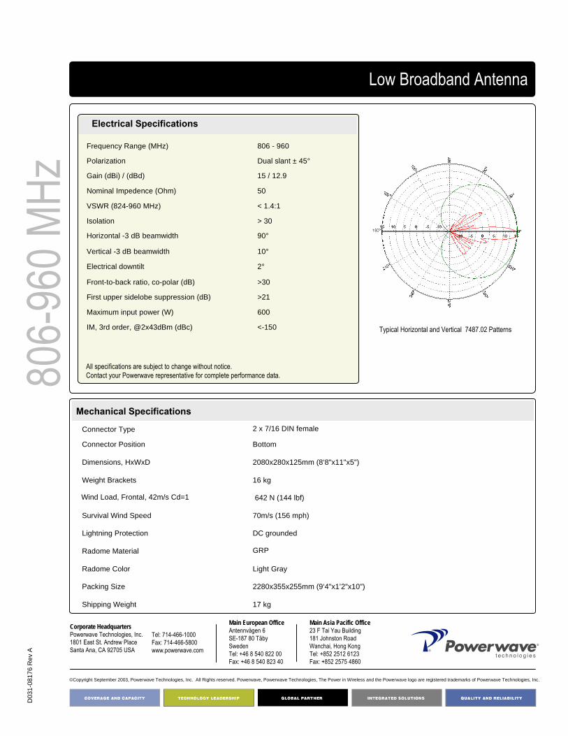
D03
1-08
176
Rev
A
©Copyright September 2003, Powerwave Technologies, Inc. All Rights reserved. Powerwave, Powerwave Technologies, The Power in Wireless and the Powerwave logo are registered trademarks of Powerwave Technologies, Inc.
Corporate HeadquartersPowerwave Technologies, Inc. 1801 East St. Andrew PlaceSanta Ana, CA 92705 USA
Tel: 714-466-1000Fax: 714-466-5800 www.powerwave.com
Main European OfficeAntennvägen 6SE-187 80 TäbySwedenTel: +46 8 540 822 00Fax: +46 8 540 823 40
Main Asia Pacific Office23 F Tai Yau Building181 Johnston RoadWanchai, Hong KongTel: +852 2512 6123Fax: +852 2575 4860
Low Broadband Antenna80
6-96
0 MHz
Mechanical Specifications
Typical Horizontal and Vertical 7487.02 Patterns
Electrical Specifications
<-150IM, 3rd order, @2x43dBm (dBc)
600 Maximum input power (W)
>21First upper sidelobe suppression (dB)
>30Front-to-back ratio, co-polar (dB)
2° Electrical downtilt
10°Vertical -3 dB beamwidth
90°Horizontal -3 dB beamwidth
> 30Isolation
< 1.4:1VSWR (824-960 MHz)
50Nominal Impedence (Ohm)
15 / 12.9Gain (dBi) / (dBd)
Dual slant ± 45°Polarization
806 - 960Frequency Range (MHz)
17 kg Shipping Weight
2280x355x255mm (9‘4"x1’2"x10")Packing Size
Light GrayRadome Color
GRPRadome Material
DC groundedLightning Protection
70m/s (156 mph)Survival Wind Speed
642 N (144 lbf)Wind Load, Frontal, 42m/s Cd=1
16 kg Weight Brackets
2080x280x125mm (8‘8"x11"x5")Dimensions, HxWxD
BottomConnector Position
2 x 7/16 DIN femaleConnector Type
All specifications are subject to change without notice.Contact your Powerwave representative for complete performance data.

806-
960 M
Hz4168.11.33.00Low Broadband Antenna
Key Benefits
• Excellent broad- and multi-band capabilities • Polarization purity maximizes diversity gain• Excellent pattern performance and high gain over
frequency• Guaranteed passive intermodulation performance• Light, slim and robust design
900 2.0 m x-polarized FET Antenna
The Powerwave broadband dual polarized antenna is designed with a slant ±45° configuration having equal signal strengths on both polarizations. The design ensures the highest possible diversity gain, isolation and cross polarization discrimination. Its slim design and sophisticated electrical performance, typical of Powerwave antennas, ensures maximum efficiency as well as stable pattern over the entire frequency range. This design relies on leading-edge patch technology fed via a micro strip PCB network. Specialattention has been paid to ensure antenna pattern peak performance, making this an excellent choice for optimal cell planning.
Part Number:7487.06 Gain: 15dBi / 12.9dBd
Horizontal Beamwidth: 90o Electrical Downtilt: 60
Connector Type: 7/16 DIN female

D03
1-08
177
Rev
A
©Copyright September 2003, Powerwave Technologies, Inc. All Rights reserved. Powerwave, Powerwave Technologies, The Power in Wireless and the Powerwave logo are registered trademarks of Powerwave Technologies, Inc.
Corporate HeadquartersPowerwave Technologies, Inc. 1801 East St. Andrew PlaceSanta Ana, CA 92705 USA
Tel: 714-466-1000Fax: 714-466-5800 www.powerwave.com
Main European OfficeAntennvägen 6SE-187 80 TäbySwedenTel: +46 8 540 822 00Fax: +46 8 540 823 40
Main Asia Pacific Office23 F Tai Yau Building181 Johnston RoadWanchai, Hong KongTel: +852 2512 6123Fax: +852 2575 4860
Low Broadband Antenna80
6-96
0 MHz
Mechanical Specifications
Typical Horizontal and Vertical 7487.06 Patterns
Electrical Specifications
<-150IM, 3rd order, @2x43dBm (dBc)
600 Maximum input power (W)
>21First upper sidelobe suppression (dB)
>30Front-to-back ratio, co-polar (dB)
6° Electrical downtilt
10°Vertical -3 dB beamwidth
90°Horizontal -3 dB beamwidth
> 30Isolation
< 1.4:1VSWR (824-960 MHz)
50Nominal Impedence (Ohm)
15 / 12.9Gain (dBi) / (dBd)
Dual slant ± 45°Polarization
806 - 960Frequency Range (MHz)
17 kg Shipping Weight
2280x355x255mm (9‘4"x1’2"x10")Packing Size
Light GrayRadome Color
GRPRadome Material
DC groundedLightning Protection
70m/s (156 mph)Survival Wind Speed
642 N (144 lbf)Wind Load, Frontal, 42m/s Cd=1
16 kg Weight Brackets
2080x280x125mm (8‘8"x11"x5")Dimensions, HxWxD
BottomConnector Position
2 x 7/16 DIN femaleConnector Type
All specifications are subject to change without notice.Contact your Powerwave representative for complete performance data.

806-
960 M
Hz4168.11.33.00Low Broadband Antenna
Key Benefits
• Excellent broad- and multi-band capabilities • Polarization purity maximizes diversity gain• Excellent pattern performance and high gain over
frequency• Guaranteed passive intermodulation performance• Light, slim and robust design
900 2.6 m x-polarized FET Antenna
The Powerwave broadband dual polarized antenna is designed with a slant ±45° configuration having equal signal strengths on both polarizations. The design ensures the highest possible diversity gain, isolation and cross polarization discrimination. Its slim design and sophisticated electrical performance, typical of Powerwave antennas, ensures maximum efficiency as well as stable pattern over the entire frequency range. This design relies on leading-edge patch technology fed via a micro strip PCB network. Specialattention has been paid to ensure antenna pattern peak performance, making this an excellent choice for optimal cell planning.
Part Number:7488.00 Gain: 16.5dBi / 14.4dBd
Horizontal Beamwidth: 90o Electrical Downtilt: 0°Connector Type: 7/16 DIN female

D03
1-08
178
Rev
A
©Copyright September 2003, Powerwave Technologies, Inc. All Rights reserved. Powerwave, Powerwave Technologies, The Power in Wireless and the Powerwave logo are registered trademarks of Powerwave Technologies, Inc.
Corporate HeadquartersPowerwave Technologies, Inc. 1801 East St. Andrew PlaceSanta Ana, CA 92705 USA
Tel: 714-466-1000Fax: 714-466-5800 www.powerwave.com
Main European OfficeAntennvägen 6SE-187 80 TäbySwedenTel: +46 8 540 822 00Fax: +46 8 540 823 40
Main Asia Pacific Office23 F Tai Yau Building181 Johnston RoadWanchai, Hong KongTel: +852 2512 6123Fax: +852 2575 4860
Low Broadband Antenna80
6-96
0 MHz
Mechanical Specifications
Typical Horizontal and Vertical 7488.00 Patterns
Electrical Specifications
<-150IM, 3rd order, @2x43dBm (dBc)
600 Maximum input power (W)
>20First upper sidelobe suppression (dB)
>30Front-to-back ratio, co-polar (dB)
0° Electrical downtilt
8°Vertical -3 dB beamwidth
90°Horizontal -3 dB beamwidth
> 30Isolation
< 1.4:1VSWR (824-960 MHz)
50Nominal Impedence (Ohm)
16.5 / 14.4Gain (dBi) / (dBd)
Dual slant ± 45°Polarization
806 - 960Frequency Range (MHz)
20 kg Shipping Weight
2800x355x255mm (9‘4"x1’2"x10")Packing Size
Light GrayRadome Color
GRPRadome Material
DC groundedLightning Protection
70m/s (156 mph)Survival Wind Speed
636 N (143 lbf)Wind Load, Frontal, 42m/s Cd=1
19 kg Weight Brackets
2600x280x125mm (8‘8"x11"x5")Dimensions, HxWxD
BottomConnector Position
2 x 7/16 DIN femaleConnector Type
All specifications are subject to change without notice.Contact your Powerwave representative for complete performance data.
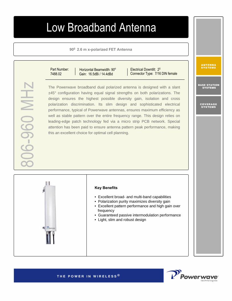
806-
960 M
Hz4168.11.33.00Low Broadband Antenna
Key Benefits
• Excellent broad- and multi-band capabilities • Polarization purity maximizes diversity gain• Excellent pattern performance and high gain over
frequency• Guaranteed passive intermodulation performance• Light, slim and robust design
900 2.6 m x-polarized FET Antenna
The Powerwave broadband dual polarized antenna is designed with a slant ±45° configuration having equal signal strengths on both polarizations. The design ensures the highest possible diversity gain, isolation and cross polarization discrimination. Its slim design and sophisticated electrical performance, typical of Powerwave antennas, ensures maximum efficiency as well as stable pattern over the entire frequency range. This design relies on leading-edge patch technology fed via a micro strip PCB network. Specialattention has been paid to ensure antenna pattern peak performance, making this an excellent choice for optimal cell planning.
Part Number:7488.02 Gain: 16.5dBi / 14.4dBd
Horizontal Beamwidth: 90o Electrical Downtilt: 20
Connector Type: 7/16 DIN female
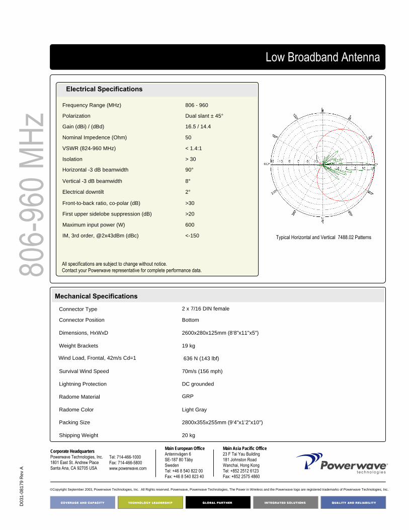
D03
1-08
179
Rev
A
©Copyright September 2003, Powerwave Technologies, Inc. All Rights reserved. Powerwave, Powerwave Technologies, The Power in Wireless and the Powerwave logo are registered trademarks of Powerwave Technologies, Inc.
Corporate HeadquartersPowerwave Technologies, Inc. 1801 East St. Andrew PlaceSanta Ana, CA 92705 USA
Tel: 714-466-1000Fax: 714-466-5800 www.powerwave.com
Main European OfficeAntennvägen 6SE-187 80 TäbySwedenTel: +46 8 540 822 00Fax: +46 8 540 823 40
Main Asia Pacific Office23 F Tai Yau Building181 Johnston RoadWanchai, Hong KongTel: +852 2512 6123Fax: +852 2575 4860
Low Broadband Antenna80
6-96
0 MHz
Mechanical Specifications
Typical Horizontal and Vertical 7488.02 Patterns
Electrical Specifications
<-150IM, 3rd order, @2x43dBm (dBc)
600 Maximum input power (W)
>20First upper sidelobe suppression (dB)
>30Front-to-back ratio, co-polar (dB)
2° Electrical downtilt
8°Vertical -3 dB beamwidth
90°Horizontal -3 dB beamwidth
> 30Isolation
< 1.4:1VSWR (824-960 MHz)
50Nominal Impedence (Ohm)
16.5 / 14.4Gain (dBi) / (dBd)
Dual slant ± 45°Polarization
806 - 960Frequency Range (MHz)
20 kg Shipping Weight
2800x355x255mm (9‘4"x1’2"x10")Packing Size
Light GrayRadome Color
GRPRadome Material
DC groundedLightning Protection
70m/s (156 mph)Survival Wind Speed
636 N (143 lbf)Wind Load, Frontal, 42m/s Cd=1
19 kg Weight Brackets
2600x280x125mm (8‘8"x11"x5")Dimensions, HxWxD
BottomConnector Position
2 x 7/16 DIN femaleConnector Type
All specifications are subject to change without notice.Contact your Powerwave representative for complete performance data.

806-
960 M
Hz4168.11.33.00Low Broadband Antenna
Key Benefits
• Excellent broad- and multi-band capabilities • Polarization purity maximizes diversity gain• Excellent pattern performance and high gain over
frequency• Guaranteed passive intermodulation performance• Light, slim and robust design
900 2.6 m x-polarized FET Antenna
The Powerwave broadband dual polarized antenna is designed with a slant ±45° configuration having equal signal strengths on both polarizations. The design ensures the highest possible diversity gain, isolation and cross polarization discrimination. Its slim design and sophisticated electrical performance, typical of Powerwave antennas, ensures maximum efficiency as well as stable pattern over the entire frequency range. This design relies on leading-edge patch technology fed via a micro strip PCB network. Specialattention has been paid to ensure antenna pattern peak performance, making this an excellent choice for optimal cell planning.
Part Number:7488.06 Gain: 16.5dBi / 14.4dBd
Horizontal Beamwidth: 90o Electrical Downtilt: 60
Connector Type: 7/16 DIN female
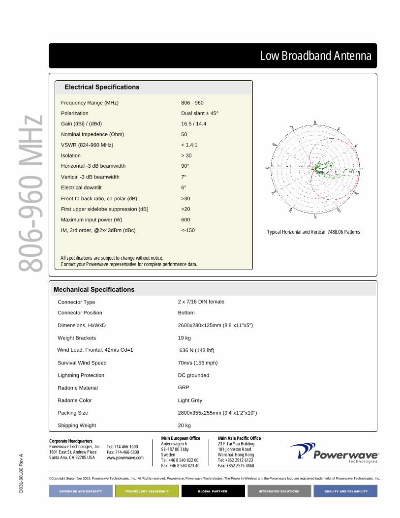
D03
1-08
180
Rev
A
©Copyright September 2003, Powerwave Technologies, Inc. All Rights reserved. Powerwave, Powerwave Technologies, The Power in Wireless and the Powerwave logo are registered trademarks of Powerwave Technologies, Inc.
Corporate HeadquartersPowerwave Technologies, Inc. 1801 East St. Andrew PlaceSanta Ana, CA 92705 USA
Tel: 714-466-1000Fax: 714-466-5800 www.powerwave.com
Main European OfficeAntennvägen 6SE-187 80 TäbySwedenTel: +46 8 540 822 00Fax: +46 8 540 823 40
Main Asia Pacific Office23 F Tai Yau Building181 Johnston RoadWanchai, Hong KongTel: +852 2512 6123Fax: +852 2575 4860
Low Broadband Antenna80
6-96
0 MHz
Mechanical Specifications
Typical Horizontal and Vertical 7488.06 Patterns
Electrical Specifications
<-150IM, 3rd order, @2x43dBm (dBc)
600 Maximum input power (W)
>20First upper sidelobe suppression (dB)
>30Front-to-back ratio, co-polar (dB)
6° Electrical downtilt
7°Vertical -3 dB beamwidth
90°Horizontal -3 dB beamwidth
> 30Isolation
< 1.4:1VSWR (824-960 MHz)
50Nominal Impedence (Ohm)
16.5 / 14.4Gain (dBi) / (dBd)
Dual slant ± 45°Polarization
806 - 960Frequency Range (MHz)
20 kg Shipping Weight
2800x355x255mm (9‘4"x1’2"x10")Packing Size
Light GrayRadome Color
GRPRadome Material
DC groundedLightning Protection
70m/s (156 mph)Survival Wind Speed
636 N (143 lbf)Wind Load, Frontal, 42m/s Cd=1
19 kg Weight Brackets
2600x280x125mm (8‘8"x11"x5")Dimensions, HxWxD
BottomConnector Position
2 x 7/16 DIN femaleConnector Type
All specifications are subject to change without notice.Contact your Powerwave representative for complete performance data.

65º 0.7 m X-polarized FET Antenna
Part Number:7216.03
Horizontal Beamwidth: 65°
Gain: 12.5 dBi / 10.4 dBdElectrical Downtilt: 0ºConnector Type: 7/16 DIN female
The Powerwave® X-Urban Single Band Antenna shares its characteristically slim design with the Urban antenna. Its outstanding performance in the field derives from excellent VSWR (Voltage Standing Wave Ratio), isolation beam squint and tracking. This design ensures minimized intermodulation products, thus substantially enhancing system benefits.
The Powerwave® polarization diversity systems use one antenna with two orthogonal polarizations slanted at +45° to provide the independently fading signals needed for achieving top-quality coverage. As a result of thorough, in-depth research and testing, Powerwave® has produced a variety of designs that ensure the isolation, cross polarization discrimination and orthogonality between inputs needed to achieve the highest possible diversity gain, hence the most efficient system performance.
880-
960 M
Hz4168.11.33.00Single Band X-Urban Antenna
Key Benefits
• High gain performance• Light and slim design• Robust and reliable• Pre-mounted brackets• Guaranteed passive intermodulation performance

D03
1-08
069
Rev
A
©Copyright September 2003, Powerwave Technologies, Inc. All Rights reserved. Powerwave, Powerwave Technologies, The Power in Wireless and the Powerwave logo are registered trademarks of Powerwave Technologies, Inc.
Corporate HeadquartersPowerwave Technologies, Inc. 1801 East St. Andrew PlaceSanta Ana, CA 92705 USA
Tel: 714-466-1000Fax: 714-466-5800 www.powerwave.com
Main European OfficeAntennvägen 6SE-187 80 TäbySwedenTel: +46 8 540 822 00Fax: +46 8 540 823 40
Main Asia Pacific Office23 F Tai Yau Building181 Johnston RoadWanchai, Hong KongTel: +852 2512 6123Fax: +852 2575 4860
Single Band X-Urban Antenna
Electrical Specifications
880-
960 M
Hz
5.5kg (12 lbs)Shipping Weight
770x308x121mm (2'6"x1"x5")Packing Size
Light grayRadome Color
PVCRadome Material
DC groundedLightning Protection
55m/s (123 mph)Survival Wind Speed
190N (57 lbf)Wind Load, Frontal, 42 m/s, Cd=1
4 kg (8.8 lbs)Weight Including Bracket
660x256x50mm (2'2"x10"x2")Dimensions, HxWxD
BottomConnector Position
7/16 DIN femaleConnector Type
Mechanical Specifications
Typical Horizontal and Vertical 7216.03 Patterns
Frequency Band (MHz) 880 – 960Gain (dBi / dBd) 12.5 / 10.4Polarization Linear slantedNominal Impedance (Ohm) 50°VSWR < 1.3.1Isolation between inputs (dB) > 30Horizontal –3 dB beamwidth 65°Tracking, Horizontal plane (dB) < 1Electrical downtilt 0°Vertical –3 dB beamwidth 26 °First upper sidelobe suppression (dB) > 10Vertical beam squint < 0.3°Front-to-back ratio, co-polar (dB) >24Front-to-back ratio, total power (dB) >20Cross-polar discrimination (dB) >20Maximum input power (W) 250IM3, @2x43dBm (dBc) <-150
All specifications are subject to change without notice.Contact your Powerwave representative for complete performance data.

65º 1.3 m X-polarized FET Antenna
Part Number:7217.03
Horizontal Beamwidth: 65°
Gain: 15.0 dBi / 12.9 dBdElectrical Downtilt: 7ºConnector Type: 7/16 DIN female
The Powerwave® X-Urban Single Band Antenna shares its characteristically slim design with the Urban antenna. Its outstanding performance in the field derives from excellent VSWR (Voltage Standing Wave Ratio), isolation beam squint and tracking. This design ensures minimized intermodulation products, thus substantially enhancing system benefits.
The Powerwave® polarization diversity systems use one antenna with two orthogonal polarizations slanted at +45° to provide the independently fading signals needed for achieving top-quality coverage. As a result of thorough, in-depth research and testing, Powerwave® has produced a variety of designs that ensure the isolation, cross polarization discrimination and orthogonality between inputs needed to achieve the highest possible diversity gain, hence the most efficient system performance.
880-
960 M
Hz4168.11.33.00Single Band X-Urban Antenna
Key Benefits
• Dual Polarization• Market Leading Performance• Light and slim design• Robust and reliable• Guaranteed passive intermodulation performance

D03
1-08
070
Rev
A
©Copyright September 2003, Powerwave Technologies, Inc. All Rights reserved. Powerwave, Powerwave Technologies, The Power in Wireless and the Powerwave logo are registered trademarks of Powerwave Technologies, Inc.
Corporate HeadquartersPowerwave Technologies, Inc. 1801 East St. Andrew PlaceSanta Ana, CA 92705 USA
Tel: 714-466-1000Fax: 714-466-5800 www.powerwave.com
Main European OfficeAntennvägen 6SE-187 80 TäbySwedenTel: +46 8 540 822 00Fax: +46 8 540 823 40
Main Asia Pacific Office23 F Tai Yau Building181 Johnston RoadWanchai, Hong KongTel: +852 2512 6123Fax: +852 2575 4860
Single Band X-Urban Antenna
Electrical Specifications
880-
960 M
Hz
10kg (22 lbs)Shipping Weight
1430x308x121mm (4’8”x1’x5”)Packing Size
Light grayRadome Color
PVCRadome Material
DC groundedLightning Protection
55 m/s (123 mph)Survival Wind Speed
1320 N (256 lbf)Wind Load, Frontal, 42 m/s, Cd=1
8.5kg (18.7 lbs)Weight Including Bracket
1320x256x50mm (4’4”x10”x2”)Dimensions, HxWxD
BottomConnector Position
7/16 DIN femaleConnector Type
Mechanical Specifications
Typical Horizontal and Vertical 7217.03 Patterns
Frequency Band (MHz) 880 – 960Gain (dBi / dBd) 15.0 / 12.9Polarization Linear slanted ± 45°Nominal Impedance (Ohm) 50VSWR < 1.3.1Isolation between inputs (dB) > 30Horizontal –3 dB beamwidth 65°Tracking, Horizontal plane (dB) < 1Electrical downtilt 7°Vertical –3 dB beamwidth 13°First upper sidelobe suppression (dB) > 14Vertical beam squint < 0.3°Front-to-back ratio, co-polar (dB) >24Front-to-back ratio, total power (dB) >20Cross-polar discrimination (dB) >19Maximum input power (W) 500IM3, @2x43dBm (dBc) <-150
All specifications are subject to change without notice.Contact your Powerwave representative for complete performance data.

65º 1.3 m X-polarized FET Antenna
Part Number:7217.04
Horizontal Beamwidth: 65°
Gain: 15.5 dBi / 13.4 dBdElectrical Downtilt: 0ºConnector Type: 7/16 DIN female
The Powerwave® X-Urban Single Band Antenna shares its characteristically slim design with the Urban antenna. Its outstanding performance in the field derives from excellent VSWR (Voltage Standing Wave Ratio), isolation beam squint and tracking. This design ensures minimized intermodulation products, thus substantially enhancing system benefits.
The Powerwave® polarization diversity systems use one antenna with two orthogonal polarizations slanted at +45° to provide the independently fading signals needed for achieving top-quality coverage. As a result of thorough, in-depth research and testing, Powerwave® has produced a variety of designs that ensure the isolation, cross polarization discrimination and orthogonality between inputs needed to achieve the highest possible diversity gain, hence the most efficient system performance.
880-
960 M
Hz4168.11.33.00Single Band X-Urban Antenna
Key Benefits
• Dual Polarization• Market Leading Performance• Light and slim design• Robust and reliable• Guaranteed passive intermodulation performance

D03
1-08
071
Rev
A
©Copyright September 2003, Powerwave Technologies, Inc. All Rights reserved. Powerwave, Powerwave Technologies, The Power in Wireless and the Powerwave logo are registered trademarks of Powerwave Technologies, Inc.
Corporate HeadquartersPowerwave Technologies, Inc. 1801 East St. Andrew PlaceSanta Ana, CA 92705 USA
Tel: 714-466-1000Fax: 714-466-5800 www.powerwave.com
Main European OfficeAntennvägen 6SE-187 80 TäbySwedenTel: +46 8 540 822 00Fax: +46 8 540 823 40
Main Asia Pacific Office23 F Tai Yau Building181 Johnston RoadWanchai, Hong KongTel: +852 2512 6123Fax: +852 2575 4860
Single Band X-Urban Antenna
Electrical Specifications
880-
960 M
Hz
10kg (22 lbs)Shipping Weight
1430x308x121mm (4’8”x1’x5”)Packing Size
Light grayRadome Color
PVCRadome Material
DC groundedLightning Protection
55 m/s (123 mph)Survival Wind Speed
1320 N (256 lbf)Wind Load, Frontal, 42 m/s, Cd=1
8.5kg (18.7 lbs)Weight Including Bracket
1320x256x50mm (4’4”x10”x2”)Dimensions, HxWxD
BottomConnector Position
7/16 DIN femaleConnector Type
Mechanical Specifications
Typical Horizontal and Vertical 7217.04 Patterns
Frequency Band (MHz) 880 – 960Gain (dBi / dBd) 15.5 / 13.4Polarization Linear slanted ± 45°Nominal Impedance (Ohm) 50VSWR < 1.3.1Isolation between inputs (dB) > 30Horizontal –3 dB beamwidth 65°Tracking, Horizontal plane (dB) < 1Electrical downtilt 0°Vertical –3 dB beamwidth 13°First upper sidelobe suppression (dB) > 14Vertical beam squint < 0.3°Front-to-back ratio, co-polar (dB) >24Front-to-back ratio, total power (dB) >20Cross-polar discrimination (dB) >19Maximum input power (W) 500IM3, @2x43dBm (dBc) <-150
All specifications are subject to change without notice.Contact your Powerwave representative for complete performance data.

65º 1.3 m X-polarized FET Antenna
Part Number:7217.01, 7217.11
Horizontal Beamwidth: 65°
Gain: 14.5 dBi / 12.4 dBdElectrical Downtilt: 9ºConnector Type: 7/16 DIN female
The Powerwave® X-Urban Single Band Antenna shares its characteristically slim design with the Urban antenna. Its outstanding performance in the field derives from excellent VSWR (Voltage Standing Wave Ratio), isolation beam squint and tracking. This design ensures minimized intermodulation products, thus substantially enhancing system benefits.
The Powerwave® polarization diversity systems use one antenna with two orthogonal polarizations slanted at +45° to provide the independently fading signals needed for achieving top-quality coverage. As a result of thorough, in-depth research and testing, Powerwave® has produced a variety of designs that ensure the isolation, cross polarization discrimination and orthogonality between inputs needed to achieve the highest possible diversity gain, hence the most efficient system performance.
880-
960 M
Hz4168.11.33.00Single Band X-Urban Antenna
Key Benefits
• Dual Polarization• Market Leading Performance• Light and slim design• Robust and reliable• Guaranteed passive intermodulation performance

D03
1-08
072
Rev
A
©Copyright September 2003, Powerwave Technologies, Inc. All Rights reserved. Powerwave, Powerwave Technologies, The Power in Wireless and the Powerwave logo are registered trademarks of Powerwave Technologies, Inc.
Corporate HeadquartersPowerwave Technologies, Inc. 1801 East St. Andrew PlaceSanta Ana, CA 92705 USA
Tel: 714-466-1000Fax: 714-466-5800 www.powerwave.com
Main European OfficeAntennvägen 6SE-187 80 TäbySwedenTel: +46 8 540 822 00Fax: +46 8 540 823 40
Main Asia Pacific Office23 F Tai Yau Building181 Johnston RoadWanchai, Hong KongTel: +852 2512 6123Fax: +852 2575 4860
Single Band X-Urban Antenna
Electrical Specifications
880-
960 M
Hz
10kg (22 lbs)Shipping Weight
1430x308x121mm (4’8”x1’x5”)Packing Size
Light grayRadome Color
PVCRadome Material
DC groundedLightning Protection
55 m/s (123 mph)Survival Wind Speed
1320 N (256 lbf)Wind Load, Frontal, 42 m/s, Cd=1
8.5kg (18.7 lbs)Weight Including Bracket
1320x256x50mm (4’4”x10”x2”)Dimensions, HxWxD
BottomConnector Position
7/16 DIN femaleConnector Type
Mechanical Specifications
Typical Horizontal and Vertical 7217.11 Patterns
Frequency Band (MHz) 880 – 960Gain (dBi / dBd) 14.5 / 12.4Polarization Linear slanted ± 45°Nominal Impedance (Ohm) 50VSWR < 1.3.1Isolation between inputs (dB) > 30Horizontal –3 dB beamwidth 65°Tracking, Horizontal plane (dB) < 1Electrical downtilt 9°Vertical –3 dB beamwidth 13°First upper sidelobe suppression (dB) > 14Vertical beam squint < 0.3°Front-to-back ratio, co-polar (dB) >23Front-to-back ratio, total power (dB) >19Cross-polar discrimination (dB) >19Maximum input power (W) 500IM3, @2x43dBm (dBc) <-150
All specifications are subject to change without notice.Contact your Powerwave representative for complete performance data.

65° 2.6 m X-polarized FET Antenna
Part Number:7218.03, 7218.13
Horizontal Beamwidth: 65°
Gain: 17.5 dBi / 15.4 dBdElectrical Downtilt: 6ºConnector Type: 7/16 DIN female
The Powerwave® X-Urban Single Band Antenna shares its characteristically slim design with the Urban antenna. Its outstanding performance in the field derives from excellent VSWR (Voltage Standing Wave Ratio), isolation beam squint and tracking. This design ensures minimized intermodulation products, thus substantially enhancing system benefits.
The Powerwave® polarization diversity systems use one antenna with two orthogonal polarizations slanted at +45° to provide the independently fading signals needed for achieving top-quality coverage. As a result of thorough, in-depth research and testing, Powerwave® has produced a variety of designs that ensure the isolation, cross polarization discrimination and orthogonality between inputs needed to achieve the highest possible diversity gain, hence the most efficient system performance.
880-
960 M
Hz4168.11.33.00Single Band X-Urban Antenna
Key Benefits
• Dual Polarization• Market Leading Performance• Light and slim design• Robust and reliable• Guaranteed passive intermodulation performance
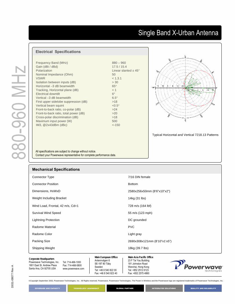
D03
1-08
077
Rev
A
©Copyright September 2003, Powerwave Technologies, Inc. All Rights reserved. Powerwave, Powerwave Technologies, The Power in Wireless and the Powerwave logo are registered trademarks of Powerwave Technologies, Inc.
Corporate HeadquartersPowerwave Technologies, Inc. 1801 East St. Andrew PlaceSanta Ana, CA 92705 USA
Tel: 714-466-1000Fax: 714-466-5800 www.powerwave.com
Main European OfficeAntennvägen 6SE-187 80 TäbySwedenTel: +46 8 540 822 00Fax: +46 8 540 823 40
Main Asia Pacific Office23 F Tai Yau Building181 Johnston RoadWanchai, Hong KongTel: +852 2512 6123Fax: +852 2575 4860
Single Band X-Urban Antenna
Electrical Specifications
880-
960 M
Hz
18kg (39.7 lbs)Shipping Weight
2690x308x121mm (8’10”x1’x5”)Packing Size
Light grayRadome Color
PVCRadome Material
DC groundedLightning Protection
55 m/s (123 mph)Survival Wind Speed
728 m/s (164 lbf)Wind Load, Frontal, 42 m/s, Cd=1
14kg (31 lbs)Weight Including Bracket
2580x256x50mm (8’6”x10”x2”)Dimensions, HxWxD
BottomConnector Position
7/16 DIN femaleConnector Type
Mechanical Specifications
Typical Horizontal and Vertical 7218.13 Patterns
Frequency Band (MHz) 880 – 960Gain (dBi / dBd) 17.5 / 15.4Polarization Linear slanted ± 45°Nominal Impedance (Ohm) 50VSWR < 1.3.1Isolation between inputs (dB) > 30Horizontal –3 dB beamwidth 65°Tracking, Horizontal plane (dB) < 1Electrical downtilt 6°Vertical –3 dB beamwidth 6.5°First upper sidelobe suppression (dB) >18Vertical beam squint <0.5°Front-to-back ratio, co-polar (dB) >24Front-to-back ratio, total power (dB) >20Cross-polar discrimination (dB) >18Maximum input power (W) 500IM3, @2x43dBm (dBc) <-150
All specifications are subject to change without notice.Contact your Powerwave representative for complete performance data.

65° 2.6 m X-polarized FET Antenna
Part Number:7218.04, 7218.14
Horizontal Beamwidth: 65°
Gain: 17.5 dBi / 15.4 dBdElectrical Downtilt: 4ºConnector Type: 7/16 DIN female
The Powerwave® X-Urban Single Band Antenna shares its characteristically slim design with the Urban antenna. Its outstanding performance in the field derives from excellent VSWR (Voltage Standing Wave Ratio), isolation beam squint and tracking. This design ensures minimized intermodulation products, thus substantially enhancing system benefits.
The Powerwave polarization diversity systems use one antenna with two orthogonal polarizations slanted at +45° to provide the independently fading signals needed for achieving top-quality coverage. As a result of thorough, in-depth research and testing, Powerwave has produced a variety of designs that ensure the isolation, cross polarization discrimination and orthogonality between inputs needed to achieve the highest possible diversity gain, hence the most efficient system performance.
880-
960 M
Hz4168.11.33.00Single Band X-Urban Antenna
Key Benefits
• Dual Polarization• Market Leading Performance• Light and slim design• Robust and reliable• Guaranteed passive intermodulation performance

D03
1-08
078
Rev
A
©Copyright September 2003, Powerwave Technologies, Inc. All Rights reserved. Powerwave, Powerwave Technologies, The Power in Wireless and the Powerwave logo are registered trademarks of Powerwave Technologies, Inc.
Corporate HeadquartersPowerwave Technologies, Inc. 1801 East St. Andrew PlaceSanta Ana, CA 92705 USA
Tel: 714-466-1000Fax: 714-466-5800 www.powerwave.com
Main European OfficeAntennvägen 6SE-187 80 TäbySwedenTel: +46 8 540 822 00Fax: +46 8 540 823 40
Main Asia Pacific Office23 F Tai Yau Building181 Johnston RoadWanchai, Hong KongTel: +852 2512 6123Fax: +852 2575 4860
Single Band X-Urban Antenna
Electrical Specifications
880-
960 M
Hz
18kg (39.7 lbs)Shipping Weight
2690x308x121mm (8’10”x1’x5”)Packing Size
Light grayRadome Color
PVCRadome Material
DC groundedLightning Protection
55 m/s (123 mph)Survival Wind Speed
728 m/s (164 lbf)Wind Load, Frontal, 42 m/s, Cd=1
14kg (31 lbs)Weight Including Bracket
2580x256x50mm (8’6”x10”x2”)Dimensions, HxWxD
BottomConnector Position
7/16 DIN femaleConnector Type
Mechanical Specifications
Typical Horizontal and Vertical 7218.14 Patterns
Frequency Band (MHz) 880 – 960Gain (dBi / dBd) 17.5 / 15.4Polarization Linear slanted ± 45°Nominal Impedance (Ohm) 50VSWR < 1.3.1Isolation between inputs (dB) > 30Horizontal –3 dB beamwidth 65°Tracking, Horizontal plane (dB) < 1Electrical downtilt 4°Vertical –3 dB beamwidth 6.5°First upper sidelobe suppression (dB) >18Vertical beam squint <0.5°Front-to-back ratio, co-polar (dB) >24Front-to-back ratio, total power (dB) >20Cross-polar discrimination (dB) >17Maximum input power (W) 500IM3, @2x43dBm (dBc) <-150
All specifications are subject to change without notice.Contact your Powerwave representative for complete performance data.

65° 2.6 m X-polarized FET Antenna
Part Number:7218.05, 7218.15
Horizontal Beamwidth: 65°
Gain: 18.0 dBi / 15.9 dBdElectrical Downtilt: 0ºConnector Type: 7/16 DIN female
The Powerwave® X-Urban Single Band Antenna shares its characteristically slim design with the Urban antenna. Its outstanding performance in the field derives from excellent VSWR (Voltage Standing Wave Ratio), isolation beam squint and tracking. This design ensures minimized intermodulation products, thus substantially enhancing system benefits.
The Powerwave® polarization diversity systems use one antenna with two orthogonal polarizations slanted at +45° to provide the independently fading signals needed for achieving top-quality coverage. As a result of thorough, in-depth research and testing, Powerwave® has produced a variety of designs that ensure the isolation, cross polarization discrimination and orthogonality between inputs needed to achieve the highest possible diversity gain, hence the most efficient system performance.
880-
960 M
Hz4168.11.33.00Single Band X-Urban Antenna
Key Benefits
• Dual Polarization• Market Leading Performance• Light and slim design• Robust and reliable• Guaranteed passive intermodulation performance

D03
1-08
079
Rev
A
©Copyright September 2003, Powerwave Technologies, Inc. All Rights reserved. Powerwave, Powerwave Technologies, The Power in Wireless and the Powerwave logo are registered trademarks of Powerwave Technologies, Inc.
Corporate HeadquartersPowerwave Technologies, Inc. 1801 East St. Andrew PlaceSanta Ana, CA 92705 USA
Tel: 714-466-1000Fax: 714-466-5800 www.powerwave.com
Main European OfficeAntennvägen 6SE-187 80 TäbySwedenTel: +46 8 540 822 00Fax: +46 8 540 823 40
Main Asia Pacific Office23 F Tai Yau Building181 Johnston RoadWanchai, Hong KongTel: +852 2512 6123Fax: +852 2575 4860
Single Band X-Urban Antenna
Electrical Specifications
880-
960 M
Hz
18kg (39.7 lbs)Shipping Weight
2690x308x121mm (8’10”x1’x5”)Packing Size
Light grayRadome Color
PVCRadome Material
DC groundedLightning Protection
55 m/s (123 mph)Survival Wind Speed
728 m/s (164 lbf)Wind Load, Frontal, 42 m/s, Cd=1
14kg (31 lbs)Weight Including Bracket
2580x256x50mm (8’6”x10”x2”)Dimensions, HxWxD
BottomConnector Position
7/16 DIN femaleConnector Type
Mechanical Specifications
Typical Horizontal and Vertical 7218.15 Patterns
Frequency Band (MHz) 880 – 960Gain (dBi / dBd) 18.0 / 15.9Polarization Linear slanted ± 45°Nominal Impedance (Ohm) 50VSWR < 1.3.1Isolation between inputs (dB) > 30Horizontal –3 dB beamwidth 65°Tracking, Horizontal plane (dB) < 1Electrical downtilt 0°Vertical –3 dB beamwidth 6.5°First upper sidelobe suppression (dB) >18Vertical beam squint <0.3°Front-to-back ratio, co-polar (dB) >24Front-to-back ratio, total power (dB) >20Cross-polar discrimination (dB) >18Maximum input power (W) 500IM3, @2x43dBm (dBc) <-150
All specifications are subject to change without notice.Contact your Powerwave representative for complete performance data.

65° 2.6 m X-polarized FET Antenna
Part Number:7218.09, 7218.19
Horizontal Beamwidth: 65°
Gain: 18.0 dBi / 15.9 dBdElectrical Downtilt: 2ºConnector Type: 7/16 DIN female
The Powerwave® X-Urban Single Band Antenna shares its characteristically slim design with the Urban antenna. Its outstanding performance in the field derives from excellent VSWR (Voltage Standing Wave Ratio), isolation beam squint and tracking. This design ensures minimized intermodulation products, thus substantially enhancing system benefits.
The Powerwave® polarization diversity systems use one antenna with two orthogonal polarizations slanted at +45° to provide the independently fading signals needed for achieving top-quality coverage. As a result of thorough, in-depth research and testing, Powerwave® has produced a variety of designs that ensure the isolation, cross polarization discrimination and orthogonality between inputs needed to achieve the highest possible diversity gain, hence the most efficient system performance.
880-
960 M
Hz4168.11.33.00Single Band X-Urban Antenna
Key Benefits
• Dual Polarization• Market Leading Performance• Light and slim design• Robust and reliable• Guaranteed passive intermodulation performance

D03
1-08
080
Rev
A
©Copyright September 2003, Powerwave Technologies, Inc. All Rights reserved. Powerwave, Powerwave Technologies, The Power in Wireless and the Powerwave logo are registered trademarks of Powerwave Technologies, Inc.
Corporate HeadquartersPowerwave Technologies, Inc. 1801 East St. Andrew PlaceSanta Ana, CA 92705 USA
Tel: 714-466-1000Fax: 714-466-5800 www.powerwave.com
Main European OfficeAntennvägen 6SE-187 80 TäbySwedenTel: +46 8 540 822 00Fax: +46 8 540 823 40
Main Asia Pacific Office23 F Tai Yau Building181 Johnston RoadWanchai, Hong KongTel: +852 2512 6123Fax: +852 2575 4860
Single Band X-Urban Antenna
Electrical Specifications
880-
960 M
Hz
18kg (39.7 lbs)Shipping Weight
2690x308x121mm (8’10”x1’x5”)Packing Size
Light grayRadome Color
PVCRadome Material
DC groundedLightning Protection
55 m/s (123 mph)Survival Wind Speed
728 m/s (164 lbf)Wind Load, Frontal, 42 m/s, Cd=1
14kg (31 lbs)Weight Including Bracket
2580x256x50mm (8’6”x10”x2”)Dimensions, HxWxD
BottomConnector Position
7/16 DIN femaleConnector Type
Mechanical Specifications
Typical Horizontal and Vertical 7218.19 Patterns
Frequency Band (MHz) 880 – 960Gain (dBi / dBd) 18.0 / 15.9Polarization Linear slanted ± 45°Nominal Impedance (Ohm) 50VSWR < 1.3.1Isolation between inputs (dB) > 30Horizontal –3 dB beamwidth 65°Tracking, Horizontal plane (dB) < 1Electrical downtilt 2°Vertical –3 dB beamwidth 6.5°First upper sidelobe suppression (dB) >18Vertical beam squint <0.4°Front-to-back ratio, co-polar (dB) >24Front-to-back ratio, total power (dB) >20Cross-polar discrimination (dB) >18Maximum input power (W) 500IM3, @2x43dBm (dBc) <-150
All specifications are subject to change without notice.Contact your Powerwave representative for complete performance data.

65º 1.9 m X-polarized FET Antenna
Part Number:7255.03, 7255.13
Horizontal Beamwidth: 65°
Gain: 16.5 dBi / 14.4 dBdElectrical Downtilt: 6ºConnector Type: 7/16 DIN female
The Powerwave® X-Urban Single Band Antenna shares its characteristically slim design with the Urban antenna. Its outstanding performance in the field derives from excellent VSWR (Voltage Standing Wave Ratio), isolation beam squint and tracking. This design ensures minimized intermodulation products, thus substantially enhancing system benefits.
The Powerwave® polarization diversity systems use one antenna with two orthogonal polarizations slanted at +45° to provide the independently fading signals needed for achieving top-quality coverage. As a result of thorough, in-depth research and testing, Powerwave® has produced a variety of designs that ensure the isolation, cross polarization discrimination and orthogonality between inputs needed to achieve the highest possible diversity gain, hence the most efficient system performance.
880-
960 M
Hz4168.11.33.00Single Band X-Urban Antenna
Key Benefits
• Dual Polarization• Market Leading Performance• Light and slim design• Robust and reliable• Guaranteed passive intermodulation performance
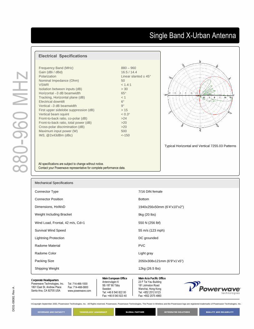
D03
1-08
081
Rev
A
©Copyright September 2003, Powerwave Technologies, Inc. All Rights reserved. Powerwave, Powerwave Technologies, The Power in Wireless and the Powerwave logo are registered trademarks of Powerwave Technologies, Inc.
Corporate HeadquartersPowerwave Technologies, Inc. 1801 East St. Andrew PlaceSanta Ana, CA 92705 USA
Tel: 714-466-1000Fax: 714-466-5800 www.powerwave.com
Main European OfficeAntennvägen 6SE-187 80 TäbySwedenTel: +46 8 540 822 00Fax: +46 8 540 823 40
Main Asia Pacific Office23 F Tai Yau Building181 Johnston RoadWanchai, Hong KongTel: +852 2512 6123Fax: +852 2575 4860
Single Band X-Urban Antenna
Electrical Specifications
880-
960 M
Hz
12kg (26.5 lbs)Shipping Weight
2050x308x121mm (6’9”x1’x5”)Packing Size
Light grayRadome Color
PVCRadome Material
DC groundedLightning Protection
55 m/s (123 mph)Survival Wind Speed
550 N (256 lbf)Wind Load, Frontal, 42 m/s, Cd=1
9kg (20 lbs)Weight Including Bracket
1940x256x50mm (6’4”x10”x2”)Dimensions, HxWxD
BottomConnector Position
7/16 DIN femaleConnector Type
Mechanical Specifications
Typical Horizontal and Vertical 7255.03 Patterns
Frequency Band (MHz) 880 – 960Gain (dBi / dBd) 16.5 / 14.4Polarization Linear slanted ± 45°Nominal Impedance (Ohm) 50VSWR < 1.4:1Isolation between inputs (dB) > 30Horizontal –3 dB beamwidth 65°Tracking, Horizontal plane (dB) < 1Electrical downtilt 6°Vertical –3 dB beamwidth 9°First upper sidelobe suppression (dB) > 15Vertical beam squint < 0.3°Front-to-back ratio, co-polar (dB) >24Front-to-back ratio, total power (dB) >20Cross-polar discrimination (dB) >20Maximum input power (W) 500IM3, @2x43dBm (dBc) <-150
All specifications are subject to change without notice.Contact your Powerwave representative for complete performance data.
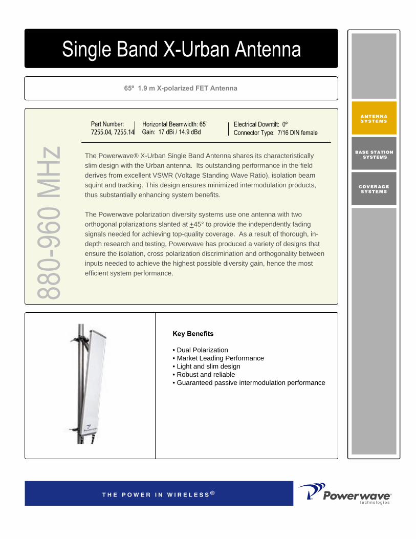
65º 1.9 m X-polarized FET Antenna
Part Number:7255.04, 7255.14
Horizontal Beamwidth: 65°
Gain: 17 dBi / 14.9 dBdElectrical Downtilt: 0ºConnector Type: 7/16 DIN female
The Powerwave® X-Urban Single Band Antenna shares its characteristically slim design with the Urban antenna. Its outstanding performance in the field derives from excellent VSWR (Voltage Standing Wave Ratio), isolation beam squint and tracking. This design ensures minimized intermodulation products, thus substantially enhancing system benefits.
The Powerwave polarization diversity systems use one antenna with two orthogonal polarizations slanted at +45° to provide the independently fading signals needed for achieving top-quality coverage. As a result of thorough, in-depth research and testing, Powerwave has produced a variety of designs that ensure the isolation, cross polarization discrimination and orthogonality between inputs needed to achieve the highest possible diversity gain, hence the most efficient system performance.
880-
960 M
Hz4168.11.33.00Single Band X-Urban Antenna
Key Benefits
• Dual Polarization• Market Leading Performance• Light and slim design• Robust and reliable• Guaranteed passive intermodulation performance

D03
1-08
082
Rev
A
©Copyright September 2003, Powerwave Technologies, Inc. All Rights reserved. Powerwave, Powerwave Technologies, The Power in Wireless and the Powerwave logo are registered trademarks of Powerwave Technologies, Inc.
Corporate HeadquartersPowerwave Technologies, Inc. 1801 East St. Andrew PlaceSanta Ana, CA 92705 USA
Tel: 714-466-1000Fax: 714-466-5800 www.powerwave.com
Main European OfficeAntennvägen 6SE-187 80 TäbySwedenTel: +46 8 540 822 00Fax: +46 8 540 823 40
Main Asia Pacific Office23 F Tai Yau Building181 Johnston RoadWanchai, Hong KongTel: +852 2512 6123Fax: +852 2575 4860
Single Band X-Urban Antenna
Electrical Specifications
880-
960 M
Hz
12kg (26.5 lbs)Shipping Weight
2050x308x121mm (6’9”x1’x5”)Packing Size
Light grayRadome Color
PVCRadome Material
DC groundedLightning Protection
55 m/s (123 mph)Survival Wind Speed
550 N (256 lbf)Wind Load, Frontal, 42 m/s, Cd=1
9kg (20 lbs)Weight Including Bracket
1940x256x50mm (6’4”x10”x2”)Dimensions, HxWxD
BottomConnector Position
7/16 DIN femaleConnector Type
Mechanical Specifications
Typical Horizontal and Vertical 7255.04 Patterns
Frequency Band (MHz) 880 – 960Gain (dBi / dBd) 17 / 14.9Polarization Linear slanted ± 45°Nominal Impedance (Ohm) 50VSWR < 1.4:1Isolation between inputs (dB) > 30Horizontal –3 dB beamwidth 65° +/- 3Tracking, Horizontal plane (dB) < 1 Electrical downtilt 0°Vertical –3 dB beamwidth 9°First upper sidelobe suppression (dB) > 17Vertical beam squint < 0.3°Front-to-back ratio, co-polar (dB) >24Front-to-back ratio, total power (dB) >20Cross-polar discrimination (dB) >20Maximum input power (W) 500IM3, @2x43dBm (dBc) <-150
All specifications are subject to change without notice.Contact your Powerwave representative for complete performance data.

65° 0.7 m x-polarized FET Antenna
Part Number7700.00
Horizontal Beamwidth: 65°Gain: 15.5 dBi
Electrical Downtilt: 0°Connector Type: 7/16 DIN
The Powerwave broadband antenna design is based on a patented stacked aperture-coupled patch technology, which provides high isolation performance and a wide VSWR bandwidth. The antennas have superior radiation patterns due to a unique reflector design that provides a very small variation of the -3dB horizontal beam width over the frequency band as well as a high front-to-back ratio. Powerwave broadband antennas come with manually adjustable electrical tilt (MET) for tuning flexibility of tilt angles. This design ensures the highest possible cross-polar discrimination value.
1710
-217
0 MHz
High Broadband Antenna
Typical Horizontal and Vertical 7700.00 Patterns

COVERAGE ANDCAPACITY
TECHNOLOGY LEADERSHIP
NETWORK OPTIMIZATION
QUALITY AND RELIABILITY
D03
1-08
189
Rev
A
Corporate HeadquartersPowerwave Technologies, Inc. 1801 East St. Andrew PlaceSanta Ana, CA 92705 USA
Tel: 714-466-1000Fax: 714-466-5800 www.powerwave.com
Main European OfficeAntennvägen 6SE-187 80 TäbySwedenTel: +46 8 540 822 00Fax: +46 8 540 823 40
©Copyright March 2005, Powerwave Technologies, Inc. All Rights reserved. Powerwave, Powerwave Technologies, The Power in Wireless and the Powerwave logo are registered trademarks of Powerwave Technologies, Inc.
Main Asia Pacific Office23 F Tai Yau Building181 Johnston RoadWanchai, Hong KongTel: +852 2512 6123Fax: +852 2575 4860
7.3 kg (16 lbs) Weight with Brackets
8.2kg (18 lbs) Shipping Weight
880x200x200mm (2'11"x8"x8“ )Packing Size
Light Gray (RAL 7035 on all visible plastic parts)Radome Color
ASARadome Material
DC GroundedLightning Protection
70m/s (156 mph)Survival Wind Speed (mph)
35 lbf (156N)Wind Load, Frontal, 100 mph(44,7m/s) Cd=1
709x167x89.5mm (2’4”x7”x4” )Dimensions, HxWxD
7/16 DIN femaleConnector TypeMechanical Specifications
High Broadband Antenna17
10-2
170 M
Hz Electrical Specifications
Frequency band (MHz) 1710-1880 1850-1990 1900-2025, 2110-2170 Gain, ± 0.5 (dBi) 15.1 15.6 15.8 Polarization Dual linear ±45° Nominal Impedance (Ohms) 50 VSWR 1.3:1 Isolation betw een inputs, 824-960MHz (dB) >30 Horizontal -3 dB beamw idth 67±3° 66±2° 64±3° Tracking,Horizontal plane, ±60° (dB) <1.0 Electrical dow ntilt 0° Vertical - 3dB Beam w idth 14.7±0.8° 13.8±0.6° 12.8±1.1° Sidelobe suppression, Vertical 1 st upper (dB) >19 Vertical beam squint 0.6° First null-f ill (dB) >-20 , typical >-18 Front-to-back ratio (dB) >30 Front-to-back ratio, total pow er (dB) >26 Cross-polar discrimination (XPD) 0° (dB) >17 >19 >19 Cross-polar discrimination ±60° (dB) >17 >15 >11 IM3, 2Tx@43dBm (dBc) <-153 <-153 IM7, 2Tx@43dBm (dBc) <-160 Pow er Handling, Average per input (W) 250 Pow er Handling, Average total (W) 500
Electrical Specifications
All specifications are subject to change without notice.Contact factory for complete performance data.

65° 0.7 m x-polarized FET Antenna
Part Number7700.06
Horizontal Beamwidth: 65°Gain: 15.5 dBi
Electrical Downtilt: 6°Connector Type: 7/16 DIN
The Powerwave broadband antenna design is based on a patented stacked aperture-coupled patch technology, which provides high isolation performance and a wide VSWR bandwidth. The antennas have superior radiation patterns due to a unique reflector design that provides a very small variation of the -3dB horizontal beam width over the frequency band as well as a high front-to-back ratio. Powerwave broadband antennas come with manually adjustable electrical tilt (MET) for tuning flexibility of tilt angles. This design ensures the highest possible cross-polar discrimination value.
1710
-217
0 MHz
High Broadband Antenna
Typical Horizontal and Vertical 7700.06 Patterns
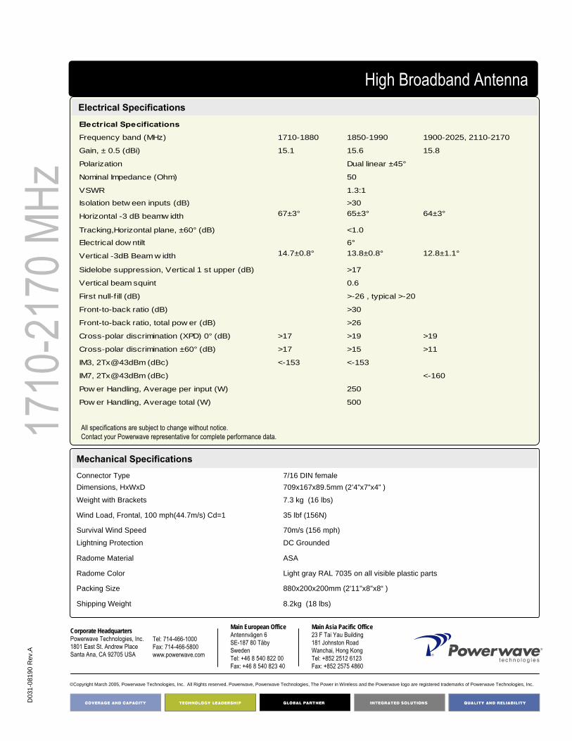
COVERAGE ANDCAPACITY
TECHNOLOGY LEADERSHIP
NETWORK OPTIMIZATION
QUALITY AND RELIABILITY
D03
1-08
190
Rev
.A
Corporate HeadquartersPowerwave Technologies, Inc. 1801 East St. Andrew PlaceSanta Ana, CA 92705 USA
Tel: 714-466-1000Fax: 714-466-5800 www.powerwave.com
Main European OfficeAntennvägen 6SE-187 80 TäbySwedenTel: +46 8 540 822 00Fax: +46 8 540 823 40
©Copyright March 2005, Powerwave Technologies, Inc. All Rights reserved. Powerwave, Powerwave Technologies, The Power in Wireless and the Powerwave logo are registered trademarks of Powerwave Technologies, Inc.
Main Asia Pacific Office23 F Tai Yau Building181 Johnston RoadWanchai, Hong KongTel: +852 2512 6123Fax: +852 2575 4860
7.3 kg (16 lbs) Weight with Brackets
8.2kg (18 lbs) Shipping Weight
880x200x200mm (2'11"x8"x8“ )Packing Size
Light gray RAL 7035 on all visible plastic partsRadome Color
ASARadome Material
DC GroundedLightning Protection
70m/s (156 mph)Survival Wind Speed
35 lbf (156N)Wind Load, Frontal, 100 mph(44.7m/s) Cd=1
709x167x89.5mm (2’4”x7”x4” )Dimensions, HxWxD7/16 DIN femaleConnector Type
Mechanical Specifications
High Broadband Antenna17
10-2
170 M
HzElectrical Specifications
Frequency band (MHz) 1710-1880 1850-1990 1900-2025, 2110-2170
Gain, ± 0.5 (dBi) 15.1 15.6 15.8
Polarization Dual linear ±45°
Nominal Impedance (Ohm) 50
VSWR 1.3:1
Isolation betw een inputs (dB) >30
Horizontal -3 dB beamw idth 67±3° 65±3° 64±3°
Tracking,Horizontal plane, ±60° (dB) <1.0
Electrical dow ntilt 6°
Vertical -3dB Beam w idth 14.7±0.8° 13.8±0.8° 12.8±1.1°
Sidelobe suppression, Vertical 1 st upper (dB) >17
Vertical beam squint 0.6
First null-f ill (dB) >-26 , typical >-20
Front-to-back ratio (dB) >30
Front-to-back ratio, total pow er (dB) >26
Cross-polar discrimination (XPD) 0° (dB) >17 >19 >19
Cross-polar discrimination ±60° (dB) >17 >15 >11
IM3, 2Tx@43dBm (dBc) <-153 <-153
IM7, 2Tx@43dBm (dBc) <-160
Pow er Handling, Average per input (W) 250
Pow er Handling, Average total (W) 500
Electrical Specifications
All specifications are subject to change without notice.Contact your Powerwave representative for complete performance data.

65° 1.3 m x-polarized FET Antenna
Part Number7701.00
Horizontal Beamwidth: 65°Gain: 18 dBi
Electrical Downtilt: 0°Connector Type: 7/16 DIN
The Powerwave broadband antenna design is based on a patented stacked aperture-coupled patch technology, which provides high isolation performance and a wide VSWR bandwidth. The antennas have superior radiation patterns due to a unique reflector design that provides a very small variation of the -3dB horizontal beam width over the frequency band as well as a high front-to-back ratio. Powerwave broadband antennas come with manually adjustable electrical tilt (MET) for tuning flexibility of tilt angles. This design ensures the highest possible cross-polar discrimination value.
1710
-217
0 MHz
High Broadband Antenna
Typical Horizontal and Vertical 7701.00 Patterns

COVERAGE ANDCAPACITY
TECHNOLOGY LEADERSHIP
NETWORK OPTIMIZATION
QUALITY AND RELIABILITY
D03
1-08
191
Rev
A Corporate HeadquartersPowerwave Technologies, Inc. 1801 East St. Andrew PlaceSanta Ana, CA 92705 USA
Tel: 714-466-1000Fax: 714-466-5800 www.powerwave.com
Main European OfficeAntennvägen 6SE-187 80 TäbySwedenTel: +46 8 540 822 00Fax: +46 8 540 823 40
©Copyright March 2005, Powerwave Technologies, Inc. All Rights reserved. Powerwave, Powerwave Technologies, The Power in Wireless and the Powerwave logo are registered trademarks of Powerwave Technologies, Inc.
Main Asia Pacific Office23 F Tai Yau Building181 Johnston RoadWanchai, Hong KongTel: +852 2512 6123Fax: +852 2575 4860
10.1 kg (22 lbs) Weight With Brackets
11kg (24.2 lbs) Shipping Weight
1480x200x200mm (4'10"x8"x8“ )Packing Size
Light gray RAL 7035 on all visible plastic partsRadome Color
ASARadome Material
DC GroundedLightning Protection70m/s (156 mph)Survival Wind Speed
70 lbf (310N)Wind Load, Frontal, 100 mph(44.7m/s) Cd=1
1309x167x89.5mm (4’4”x7”x4” )Dimensions, HxWxD
7/16 DIN femaleConnector Type
Mechanical Specifications
High Broadband Antenna17
10-2
170 M
HzElectrical SpecificationsFrequency band (MHz) 1710-1880 1850-1990 1900-2025,2110-2170Gain, ± 0.5 (dBi) 17.5 18 18.3Polarization Dual linear ±45°Nominal Impedance (Ohm) 50VSWR 1.3:1Isolation betw een inputs (dB) >30Horizontal -3 dB beamw idth 67±3° 66±2° 64±3°
Tracking,Horizontal plane, ±60° (dB) <1.0Electrical dow ntilt 0°Vertical -3dB Beam w idth 7.2±0.4° 6.7±0.3° 6.4±0.5°Sidelobe suppression, Vertical 1st upper (dB) >20Vertical beam squint 0.5°First null-f ill (dB) >-20 , typical >-18Front-to-back ratio (dB) >30Front-to-back ratio, total pow er (dB) >27Cross-polar discrimination (XPD) 0° (dB) >17 >19 >20Cross-polar discrimination ±60° (dB) >17 >14 >11IM3, 2Tx@43dBm (dBc) <-153 <-150IM7, 2Tx@43dBm (dBc) <-160Pow er Handling, Average per input (W) 250Pow er Handling, Average total (W) 500
Electrical Specifications
All specifications are subject to change without notice.Contact factory for complete performance data.
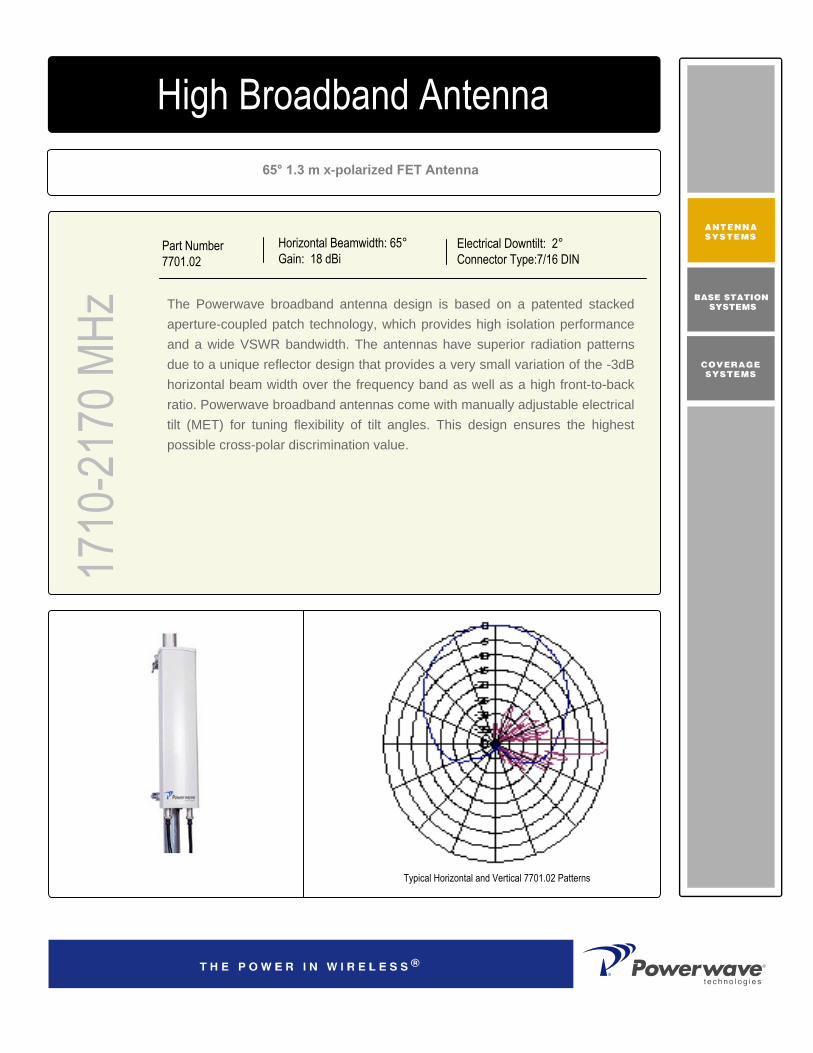
65° 1.3 m x-polarized FET Antenna
Part Number7701.02
Horizontal Beamwidth: 65°Gain: 18 dBi
Electrical Downtilt: 2°Connector Type:7/16 DIN
The Powerwave broadband antenna design is based on a patented stacked aperture-coupled patch technology, which provides high isolation performance and a wide VSWR bandwidth. The antennas have superior radiation patterns due to a unique reflector design that provides a very small variation of the -3dB horizontal beam width over the frequency band as well as a high front-to-back ratio. Powerwave broadband antennas come with manually adjustable electrical tilt (MET) for tuning flexibility of tilt angles. This design ensures the highest possible cross-polar discrimination value.
1710
-217
0 MHz
High Broadband Antenna
Typical Horizontal and Vertical 7701.02 Patterns

COVERAGE ANDCAPACITY
TECHNOLOGY LEADERSHIP
NETWORK OPTIMIZATION
QUALITY AND RELIABILITY
D03
1-08
192
Rev
A
Corporate HeadquartersPowerwave Technologies, Inc. 1801 East St. Andrew PlaceSanta Ana, CA 92705 USA
Tel: 714-466-1000Fax: 714-466-5800 www.powerwave.com
Main European OfficeAntennvägen 6SE-187 80 TäbySwedenTel: +46 8 540 822 00Fax: +46 8 540 823 40
©Copyright March 2005, Powerwave Technologies, Inc. All Rights reserved. Powerwave, Powerwave Technologies, The Power in Wireless and the Powerwave logo are registered trademarks of Powerwave Technologies, Inc.
Main Asia Pacific Office23 F Tai Yau Building181 Johnston RoadWanchai, Hong KongTel: +852 2512 6123Fax: +852 2575 4860
10.1 kg (22 lbs) Weight with Brackets
11kg (24.2 lbs) Shipping Weight
1480x200x200mm (4'10"x8"x8“ )Packing Size
Light Gray RAL 7035 on all visible plastic partsRadome Color
ASARadome Material
DC GroundedLightning Protection70m/s (156 mph)Survival Wind Speed
310N (70 lbf)Wind Load, Frontal, 100 Mph Cd=1
1309x167x89.5mm (4’4”x7”x4” )Dimensions, HxWxD7/16 DIN female Connector Type
Mechanical Specifications
High Broadband Antenna17
10-2
170 M
HzFrequency band (MHz) 1710-1880 1850-1990 1900-2025,2110-2170Gain, ± 0.5 (dBi) 17.5 18 18.3Polarization Dual linear ±45°Nominal Impedance (Ohms) 50VSWR 1.3:1Isolation betw een inputs (dB) >30Horizontal -3 dB beamw idth 67±3° 66±2° 64±3°Tracking,Horizontal plane, ±60° (dB) <1.0Electrical dow ntilt 2°Vertical -3dB Beam w idth 7.2±0.4° 6.7±0.3° 6.4±0.5°Sidelobe suppression, Vertical 1 st upper (dB) >19Vertical beam squint 0.5°First null-f ill (dB) >-22 , typical >-18Front-to-back ratio (dB) >30Front-to-back ratio, total pow er (dB) >26Cross-polar discrimination (XPD) 0° (dB) >17 >19 >20Cross-polar discrimination ±60° (dB) >17 >14 >11IM3, 2Tx@43dBm (dBc) <-153 <-150IM7, 2Tx@43dBm (dBc) <-160Pow er Handling, Average per input (W) 250Pow er Handling, Average total (W) 500
Electrical Specifications
All specifications are subject to change without notice.Contact your Powerwave representative for complete performance data.
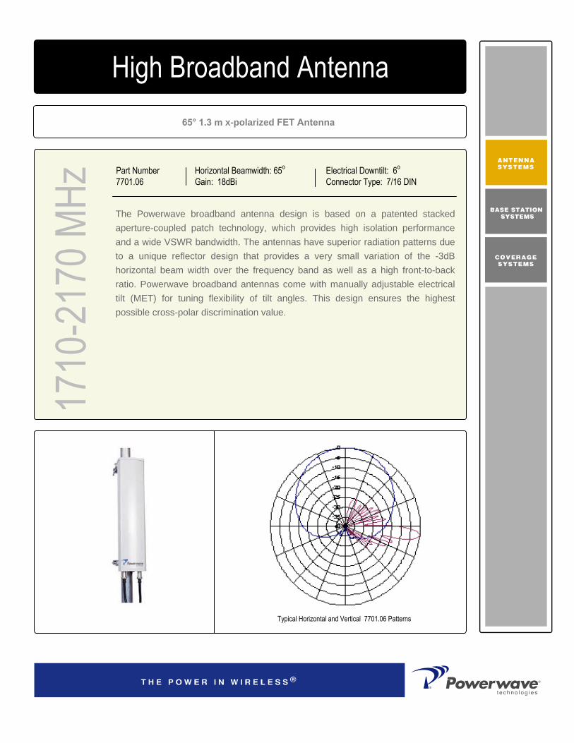
65° 1.3 m x-polarized FET Antenna
Part Number7701.06
Horizontal Beamwidth: 65o
Gain: 18dBiElectrical Downtilt: 6o
Connector Type: 7/16 DIN
The Powerwave broadband antenna design is based on a patented stacked aperture-coupled patch technology, which provides high isolation performance and a wide VSWR bandwidth. The antennas have superior radiation patterns due to a unique reflector design that provides a very small variation of the -3dB horizontal beam width over the frequency band as well as a high front-to-back ratio. Powerwave broadband antennas come with manually adjustable electrical tilt (MET) for tuning flexibility of tilt angles. This design ensures the highest possible cross-polar discrimination value.
1710
-217
0 MHz
High Broadband Antenna
Typical Horizontal and Vertical 7701.06 Patterns

COVERAGE ANDCAPACITY
TECHNOLOGY LEADERSHIP
NETWORK OPTIMIZATION
QUALITY AND RELIABILITY
D03
1-08
193
Rev
A
Corporate HeadquartersPowerwave Technologies, Inc. 1801 East St. Andrew PlaceSanta Ana, CA 92705 USA
Tel: 714-466-1000Fax: 714-466-5800 www.powerwave.com
Main European OfficeAntennvägen 6SE-187 80 TäbySwedenTel: +46 8 540 822 00Fax: +46 8 540 823 40
©Copyright March 2005, Powerwave Technologies, Inc. All Rights reserved. Powerwave, Powerwave Technologies, The Power in Wireless and the Powerwave logo are registered trademarks of Powerwave Technologies, Inc.
Main Asia Pacific Office23 F Tai Yau Building181 Johnston RoadWanchai, Hong KongTel: +852 2512 6123Fax: +852 2575 4860
10.1 kg (22 lbs) Weight With Brackets
11kg (24.2 lbs) Shipping Weight
1480x200x200mm (4'10"x8"x8“ )Packing Size
Light gray RAL 7035 on all visible plastic partsRadome Color
ASARadome Material
DC GroundedLightning Protection
70m/s (156 mph)Survival Wind Speed
310N (70 lbf)Wind Load, Frontal, 100 mph(44.7m/s) Cd=1
1309x167x89.5mm (4’4”x7”x4” )Dimensions, HxWxD
7/16 DIN femaleConnector TypeMechanical Specifications
High Broadband Antenna17
10-2
170 M
HzFrequency band (MHz) 1710-1880 1850-1990 1900-2025,2110-2170Gain, ± 0.5 (dBi) 17.5 18 18.3Polarization Dual linear ±45°Nominal Impedance (Ohms) 50VSWR 1.3:1Isolation betw een inputs (dB) >30Horizontal -3 dB beamw idth 67±3° 65±3° 64±3°
Tracking,Horizontal plane, ±60° (dB) <1.0Electrical dow ntilt 6°Vertical -3dB Beam w idth 7.2±0.4° 6.7±0.3° 6.4±0.5°Sidelobe suppression, Vertical 1 st upper (dB) >18Vertical beam squint 0.5°First null-fill (dB) >-26 , ty pical >-20Front-to-back ratio (dB) >29Front-to-back ratio, total pow er (dB) >25Cross-polar discrimination (XPD) 0° (dB) >17 >19 >20Cross-polar discrimination ±60° (dB) >17 >14 >11IM3, 2Tx @43dBm (dBc) <-153 <-153IM7, 2Tx @43dBm (dBc) <-160Pow er Handling, Av erage per input (W) 250Pow er Handling, Av erage total (W) 500
Electrical Specifications
All specifications are subject to change without notice.Contact factory for complete performance data.
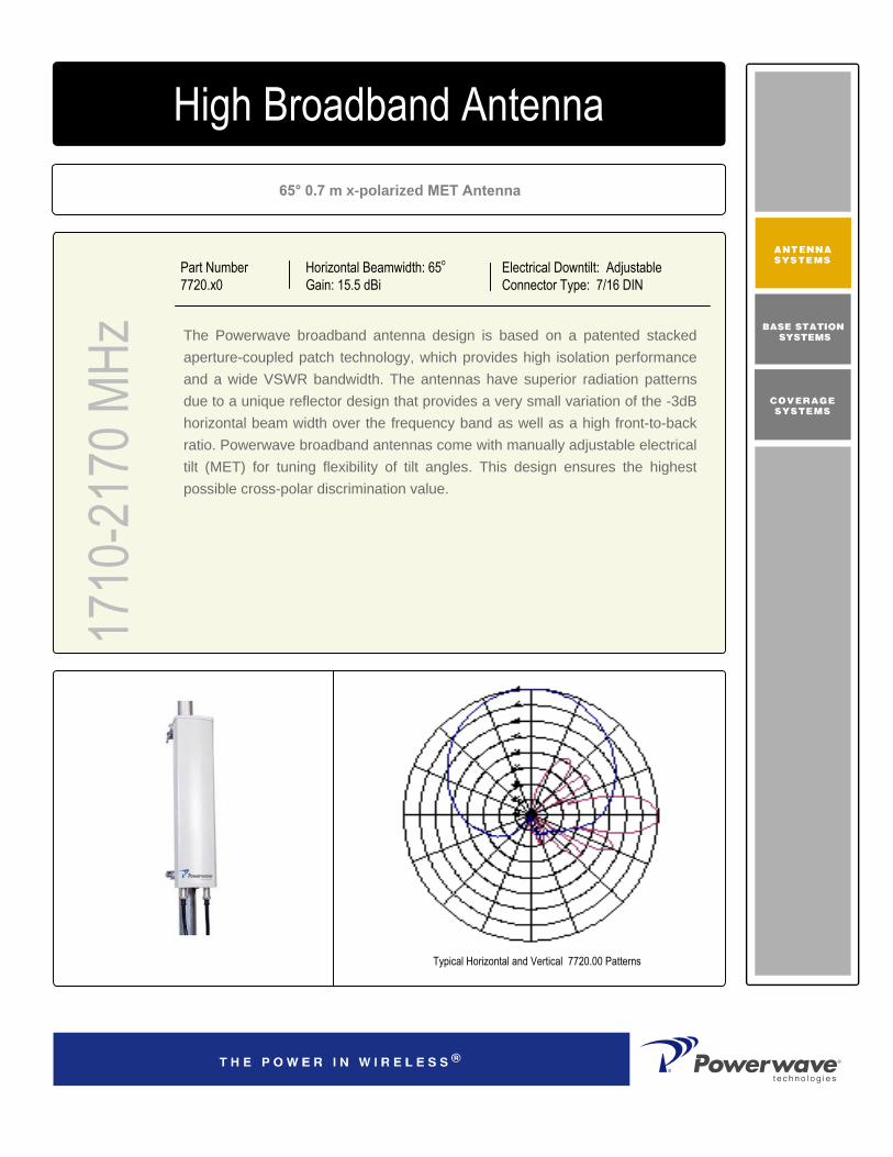
65° 0.7 m x-polarized MET Antenna
Part Number7720.x0
Horizontal Beamwidth: 65o
Gain: 15.5 dBiElectrical Downtilt: Adjustable Connector Type: 7/16 DIN
The Powerwave broadband antenna design is based on a patented stacked aperture-coupled patch technology, which provides high isolation performance and a wide VSWR bandwidth. The antennas have superior radiation patterns due to a unique reflector design that provides a very small variation of the -3dB horizontal beam width over the frequency band as well as a high front-to-back ratio. Powerwave broadband antennas come with manually adjustable electrical tilt (MET) for tuning flexibility of tilt angles. This design ensures the highest possible cross-polar discrimination value.
1710
-217
0 MHz
High Broadband Antenna
Typical Horizontal and Vertical 7720.00 Patterns
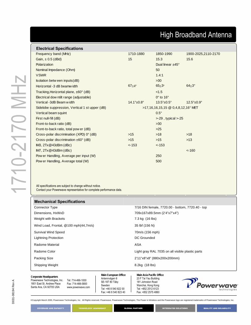
COVERAGE ANDCAPACITY
TECHNOLOGY LEADERSHIP
NETWORK OPTIMIZATION
QUALITY AND RELIABILITY
D03
1-08
194
Rev
A
Corporate HeadquartersPowerwave Technologies, Inc. 1801 East St. Andrew PlaceSanta Ana, CA 92705 USA
Tel: 714-466-1000Fax: 714-466-5800 www.powerwave.com
Main European OfficeAntennvägen 6SE-187 80 TäbySwedenTel: +46 8 540 822 00Fax: +46 8 540 823 40
©Copyright March 2005, Powerwave Technologies, Inc. All Rights reserved. Powerwave, Powerwave Technologies, The Power in Wireless and the Powerwave logo are registered trademarks of Powerwave Technologies, Inc.
Main Asia Pacific Office23 F Tai Yau Building181 Johnston RoadWanchai, Hong KongTel: +852 2512 6123Fax: +852 2575 4860
7.3 kg (16 lbs) Weight with Brackets
8.2kg (18 lbs) Shipping Weight
2’11”x8”x8” (880x200x200mm)Packing Size
Light gray RAL 7035 on all visible plastic partsRadome Color
ASARadome Material
DC GroundedLightning Protection
70m/s (156 mph)Survival Wind Speed
35 lbf (156 N)Wind Load, Frontal, @100 mph(44,7m/s)
709x167x89.5mm (2’4”x7”x4”)Dimensions, HxWxD
7/16 DIN female, 7720.00 - bottom, 7720.40 - topConnector Type
Mechanical Specifications
High Broadband Antenna17
10-2
170 M
HzElectrical SpecificationsFrequency band (MHz) 1710-1880 1850-1990 1900-2025,2110-2170Gain, ± 0.5 (dBd) 15 15.3 15.6Polarization Dual linear ±45°Nominal Impedance (Ohm) 50VSWR 1.4:1Isolation betw een inputs(dB) >30Horizontal -3 dB beamw idth 67±4° 65±3° 64±3°
Tracking,Horizontal plane, ±60° (dB) <1.5Electrical dow ntilt range (adjustable) 0° to 16°Vertical -3dB Beam w idth 14.1°±0.8° 13.5°±0.5° 12.5°±0.9°Sidelobe suppression, Vertical 1 st upper (dB) >17,16,16,15,15 @ 0,4,8,12,16° METVertical beam squint 0.5°First null-f ill (dB) >-29 , typical >-25Front-to-back ratio (dB) >30Front-to-back ratio, total pow er (dB) >25Cross-polar discrimination (XPD) 0° (dB) >15 >18 >18Cross-polar discrimination ±60° (dB) >15 >15 >13IM3, 2Tx@43dBm (dBc) <-153 <-153IM7, 2Tx@43dBm (dBc) <-160Pow er Handling, Average per input (W) 250Pow er Handling, Average total (W) 500
Electrical Specifications
All specifications are subject to change without notice.Contact your Powerwave representative for complete performance data.

65° 1.3 m x-polarized MET Antenna
Part Number:7721.x0
Horizontal Beamwidth: 65°
Gain: 18 dBiElectrical Downtilt: AdjustableConnector Type: 7/16 DIN
The Powerwave broadband antenna design is based on a patented stacked aperture-coupled patch technology, which provides high isolation performance and a wide VSWR bandwidth. The antennas have superior radiation patterns due to a unique reflector design that provides a very small variation of the -3dB horizontal beamwidth over the frequency band, as well as a high front-to-back ratio. Powerwave broadband antennas come with Manually adjustable Electrical Tilt (MET) which offers operators flexibility in turning of tilt angles, as well as logistical advantages, and is Remote Electrical Tilt (RET) upgradeable. This design ensures the highest possible cross-polar discrimination value.
1710
-217
0 MHz
4168.11.33.00High Broadband Antenna
Key Benefits
• Excellent broad- and multi-band capabilities • Polarization purity makes good diversity gain• Excellent pattern performance and high gain over
frequency• High passive intermodulation performance• Light, slim and robust design

Do3
1-08
195
Rev
A
Corporate HeadquartersPowerwave Technologies, Inc. 1801 East St. Andrew PlaceSanta Ana, CA 92705 USA
Tel: 714-466-1000Fax: 714-466-5800 www.powerwave.com
Main European OfficeAntennvägen 6SE-187 80 TäbySwedenTel: +46 8 540 822 00Fax: +46 8 540 823 40
©Copyright March 2005, Powerwave Technologies, Inc. All Rights reserved. Powerwave, Powerwave Technologies, The Power in Wireless and the Powerwave logo are registered trademarks of Powerwave Technologies, Inc.
Main Asia Pacific Office23 F Tai Yau Building181 Johnston RoadWanchai, Hong KongTel: +852 2512 6123Fax: +852 2575 4860
10.1 kg (22 lbs) Weight with Brackets
11kg (24.2 lbs)Shipping Weight
1480x200x200mm (4'10"x8"x8")Packing Size
Light Gray (RAL 7035 on all visible plastic parts)Radome Color
ASARadome Material
DC groundedLightning Protection
70m/s (156 mph)Survival Wind Speed
310N (70 lbf)Wind Load, Frontal, 100 mph(44.7m/s) Cd=1
1309x167x89.5mm (4’4”x7”x4”)Dimensions, HxWxD
7/16 DIN female, 7721.00 - bottom, 7721.40 - topConnector Type
Mechanical Specifications
High Broadband Antenna17
10-2
170 M
Hz Frequency band (MHz) 1710-1880 1850-1990 1900-2025,2110-2170
Gain, ± 0.5 (dBi) 17.5 18 18.3Polarization Dual linear ±45°Nominal Impedance (Ohm) 50VSWR 1.4:1Isolation between inputs (dB) 30Horizontal -3 dB Beam width 66 ± 2°Tracking,horizontal plane, ±60° (dB) <1.0Electrical downtilt range (adjustable) 0 ° to 8 °Vertical -3dB Beam width 7 ± 0.4° 6.6 ± 0.4° 6.3 ± 0.6°Sidelobe suppression, vertical 1st upper (dB) >18,18,16,16,14 @ 0,2,4,6,8° METVertical beam squint 0.5°First null-fill (dB) >-24 , typical >-18Front-to-back ratio (dB) >30Front-to-back ratio, total power (dB) >27Cross-polar discrimination (XPD) 0° (dB) >17 >19 >20Cross-polar discrimination ±60° (dB) >18 >14 >12
IM3, 2Tx@43dBm (dBc) <-153 <-153IM7, 2Tx@43dBm (dBc) < -160
Power Handling, Average Per Input (W) 250Power Handling, Average Total (W) 500
Electrical Specifications
67 ± 3° 64 ± 3°
Typical Horizontal and Vertical 7721.00 Patterns
All specifications are subject to change without notice.Contact your Powerwave representative for complete performance data.
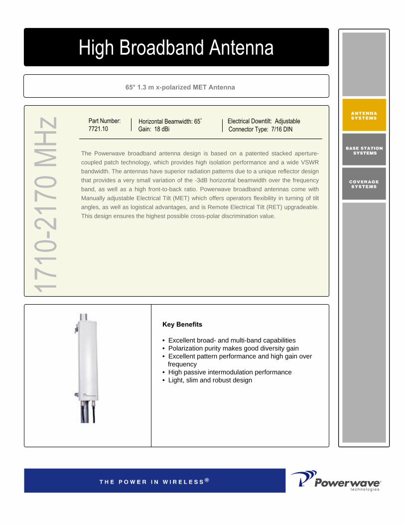
65° 1.3 m x-polarized MET Antenna
Part Number:7721.10
Horizontal Beamwidth: 65°
Gain: 18 dBiElectrical Downtilt: AdjustableConnector Type: 7/16 DIN
The Powerwave broadband antenna design is based on a patented stacked aperture-coupled patch technology, which provides high isolation performance and a wide VSWR bandwidth. The antennas have superior radiation patterns due to a unique reflector design that provides a very small variation of the -3dB horizontal beamwidth over the frequency band, as well as a high front-to-back ratio. Powerwave broadband antennas come with Manually adjustable Electrical Tilt (MET) which offers operators flexibility in turning of tilt angles, as well as logistical advantages, and is Remote Electrical Tilt (RET) upgradeable. This design ensures the highest possible cross-polar discrimination value.
1710
-217
0 MHz
4168.11.33.00High Broadband Antenna
Key Benefits
• Excellent broad- and multi-band capabilities • Polarization purity makes good diversity gain• Excellent pattern performance and high gain over
frequency• High passive intermodulation performance• Light, slim and robust design
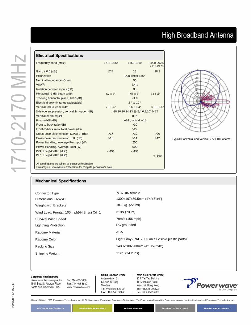
D03
1-08
196
Rev
A
Corporate HeadquartersPowerwave Technologies, Inc. 1801 East St. Andrew PlaceSanta Ana, CA 92705 USA
Tel: 714-466-1000Fax: 714-466-5800 www.powerwave.com
Main European OfficeAntennvägen 6SE-187 80 TäbySwedenTel: +46 8 540 822 00Fax: +46 8 540 823 40
©Copyright March 2005, Powerwave Technologies, Inc. All Rights reserved. Powerwave, Powerwave Technologies, The Power in Wireless and the Powerwave logo are registered trademarks of Powerwave Technologies, Inc.
Main Asia Pacific Office23 F Tai Yau Building181 Johnston RoadWanchai, Hong KongTel: +852 2512 6123Fax: +852 2575 4860
10.1 kg (22 lbs) Weight with Brackets
11kg (24.2 lbs)Shipping Weight
1480x200x200mm (4'10"x8"x8")Packing Size
Light Gray (RAL 7035 on all visible plastic parts)Radome Color
ASARadome Material
DC groundedLightning Protection
70m/s (156 mph)Survival Wind Speed
310N (70 lbf)Wind Load, Frontal, 100 mph(44.7m/s) Cd=1
1309x167x89.5mm (4’4”x7”x4”)Dimensions, HxWxD
7/16 DIN femaleConnector Type
Mechanical Specifications
High Broadband Antenna17
10-2
170 M
Hz Frequency band (MHz) 1710-1880 1850-1990 1900-2025,2110-2170
Gain, ± 0.5 (dBi) 17.5 18 18.3Polarization Dual linear ±45°Nominal Impedance (Ohm) 50VSWR 1.4:1Isolation between inputs (dB) 30Horizontal -3 dB Beam width 66 ± 2°Tracking,horizontal plane, ±60° (dB) <1.0Electrical downtilt range (adjustable) 2 ° to 10 °Vertical -3dB Beam width 7 ± 0.4° 6.6 ± 0.4° 6.3 ± 0.6°Sidelobe suppression, vertical 1st upper (dB) >18,16,16,14,13 @ 2,4,6,8,10° METVertical beam squint 0.5°First null-fill (dB) >-24 , typical >-18Front-to-back ratio (dB) >30Front-to-back ratio, total power (dB) >27Cross-polar discrimination (XPD) 0° (dB) >17 >19 >20Cross-polar discrimination ±60° (dB) >18 >14 >12
IM3, 2Tx@43dBm (dBc) <-153 <-153IM7, 2Tx@43dBm (dBc) < -160
Power Handling, Average Per Input (W) 250Power Handling, Average Total (W) 500
Electrical Specifications
67 ± 3° 64 ± 3°
Typical Horizontal and Vertical 7721.10 Patterns
All specifications are subject to change without notice.Contact your Powerwave representative for complete performance data.
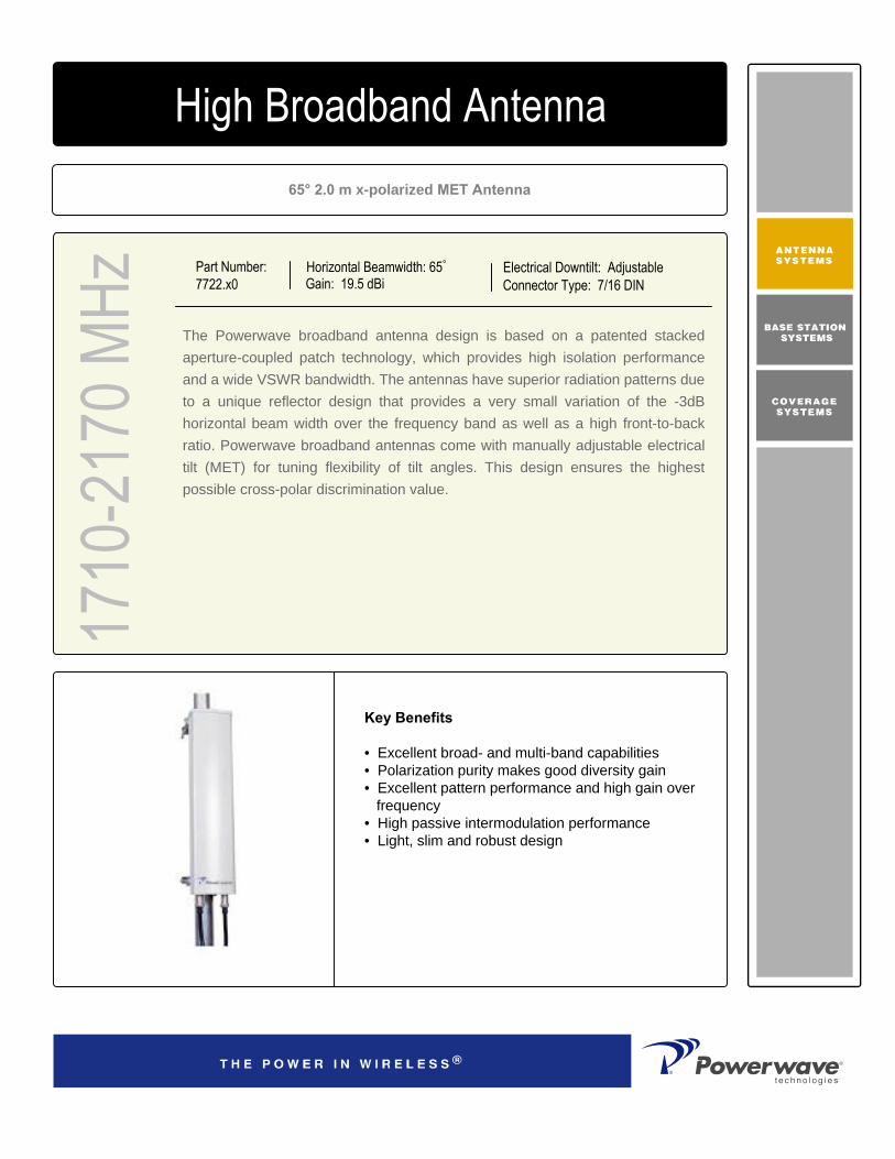
65° 2.0 m x-polarized MET Antenna
Part Number:7722.x0
Horizontal Beamwidth: 65°
Gain: 19.5 dBiElectrical Downtilt: AdjustableConnector Type: 7/16 DIN
The Powerwave broadband antenna design is based on a patented stacked aperture-coupled patch technology, which provides high isolation performance and a wide VSWR bandwidth. The antennas have superior radiation patterns due to a unique reflector design that provides a very small variation of the -3dB horizontal beam width over the frequency band as well as a high front-to-back ratio. Powerwave broadband antennas come with manually adjustable electrical tilt (MET) for tuning flexibility of tilt angles. This design ensures the highest possible cross-polar discrimination value.
1710
-217
0 MHz
4168.11.33.00High Broadband Antenna
Key Benefits
• Excellent broad- and multi-band capabilities • Polarization purity makes good diversity gain• Excellent pattern performance and high gain over
frequency• High passive intermodulation performance• Light, slim and robust design
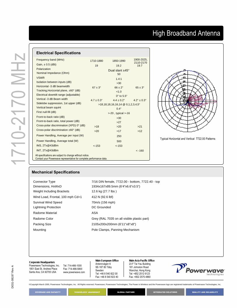
D03
1-08
197
Rev
A
Corporate HeadquartersPowerwave Technologies, Inc. 1801 East St. Andrew PlaceSanta Ana, CA 92705 USA
Tel: 714-466-1000Fax: 714-466-5800 www.powerwave.com
Main European OfficeAntennvägen 6SE-187 80 TäbySwedenTel: +46 8 540 822 00Fax: +46 8 540 823 40
©Copyright March 2005, Powerwave Technologies, Inc. All Rights reserved. Powerwave, Powerwave Technologies, The Power in Wireless and the Powerwave logo are registered trademarks of Powerwave Technologies, Inc.
Main Asia Pacific Office23 F Tai Yau Building181 Johnston RoadWanchai, Hong KongTel: +852 2512 6123Fax: +852 2575 4860
12.6 kg (27.7 lbs )Weight Including Brackets
Pole Clamps, Panning MechanismMounting
2105x200x200mm (6'11"x8"x8")Packing Size
Grey (RAL 7035 on all visible plastic part)Radome Color
ASARadome Material
DC GroundedLightning Protection70m/s (156 mph)Survival Wind Speed
412 N (92.6 lbf)Wind Load, Frontal, 100 mph Cd=1
1934x167x89.5mm (6’4”x6.6”x3.5”)Dimensions, HxWxD7/16 DIN female, 7722.00 - bottom, 7722.40 - topConnector Type
High Broadband Antenna17
10-2
170 M
HzElectrical SpecificationsFrequency band (MHz) 1710-1880 1850-1990Gain, ± 0.5 (dBi) 19 19.2 19.7Polarization Dual slant ±45°Nominal Impedance (Ohm) 50VSWR 1.4:1Isolation between inputs (dB) >30Horizontal -3 dB beamwidth 67 ± 3° 66 ± 2° 65 ± 3°Tracking,Horizontal plane, ±60° (dB) <1.0Electrical downtilt range (adjustable) 0° to 5.5°Vertical -3 dB Beam width 4.7 ± 0.3° 4.4 ± 0.2° 4.2° ± 0.3°Sidelobe suppression, 1st upper (dB) >18,18,18,16,16,14 @ 0,1,2,3,4,5°Vertical beam squint 0.4°First null-fill (dB) >-20 , typical >-16Front-to-back ratio (dB) >30Front-to-back ratio, total power (dB) >27Cross-polar discrimination (XPD) 0° (dB) >18 >20 >21Cross-polar discrimination ±60° (dB) >20 >17 >12
IM3, 2Tx@43dBm <-153 <-153
IM7, 2Tx@43dBm < -160
Power Handling, Average per input (W) 250
Power Handling, Average total (W) 500
Mechanical Specifications
1900-2025,2110-2170
Typical Horizontal and Vertical 7722.00 Patterns
All specifications are subject to change without notice.Contact your Powerwave representative for complete performance data.

90° 0.7 m x-polarized MET Antenna
Part Number7735.x0
Horizontal Beamwidth: 90° Gain: 13.5 dBi
Electrical Downtilt: Adjustable Connector Type: 7/16 DIN
The Powerwave broadband antenna design is based on a patented stacked aperture-coupled patch technology, which provides high isolation performance and a wide VSWR bandwidth. The antennas have superior radiation patterns due to a unique reflector design that provides a very small variation of the -3dB horizontal beam width over the frequency band as well as a high front-to-back ratio. Powerwave broadband antennas come with manually adjustable electrical tilt (MET) for tuning flexibility of tilt angles. This design ensures the highest possible cross-polar discrimination value.
1710
-217
0 MHz
High Broadband Antenna
Typical Horizontal and Vertical 7735.00 Patterns

COVERAGE ANDCAPACITY
TECHNOLOGY LEADERSHIP
NETWORK OPTIMIZATION
QUALITY AND RELIABILITY
D03
1-08
198
Rev
A
Corporate HeadquartersPowerwave Technologies, Inc. 1801 East St. Andrew PlaceSanta Ana, CA 92705 USA
Tel: 714-466-1000Fax: 714-466-5800 www.powerwave.com
Main European OfficeAntennvägen 6SE-187 80 TäbySwedenTel: +46 8 540 822 00Fax: +46 8 540 823 40
©Copyright March 2005, Powerwave Technologies, Inc. All Rights reserved. Powerwave, Powerwave Technologies, The Power in Wireless and the Powerwave logo are registered trademarks of Powerwave Technologies, Inc.
Main Asia Pacific Office23 F Tai Yau Building181 Johnston RoadWanchai, Hong KongTel: +852 2512 6123Fax: +852 2575 4860
8.2 kg (18 lbs) Weight With Brackets
9.1 kg (20 lbs) Shipping Weight880x200x200mm (2’11”x8”x8” )Packing Size
Light GrayRadome Color
PVCRadome Material
DC groundedLightning Protection
70 m/s (156 mph) Survival Wind Speed
35 lbf (156 N)Wind Load, Frontal, 100 mph Cd=1
709x167x89mm (2’4”x7”x4” )Dimensions, Hxwxd
BottomConnector Position7/16 DIN female, 7735.00 - bottom, 7735.40 - topConnector Type
Mechanical Specifications
High Broadband Antenna17
10-2
170 M
HzElectrical SpecificationsFrequency band (MHz) 1710-1880 1850-1990 1900-2025,2110-2170Gain, ± 0.5 (dBi) 13.5 13.5 13.7Polarization Dual linear ±45°Nominal Impedance (Ohms) 50VSWR 1.4:1Isolation betw een inputs (dB) >30Horizontal -3 dB beamw idth 86±3° 86±3° 87±4°Tracking,Horizontal plane, ±60° (dB) <1.0Electrical dow ntilt range (adjustable) 0° to 16°Vertical -3dB Beam w idth 14.7°±1° 13.4°±1° 12.2°±1°Sidelobe suppression, 1st upper (dB) >18,17,16,15,14@ 0, 4, 8, 12 ,16° METVertical beam squint 0.8°First null-f ill (dB) >-24 , typical >-18Front-to-back ratio (dB) >25Front-to-back ratio, total pow er (dB) >23Cross-polar discrimination (XPD) 0°(dB) >13 >13 >12Cross-polar discrimination ±60° (dB) >10 >10 >10IM3, 2Tx@43dBm (dBc) -153 -153IM7, 2Tx@43dBm (dBc) -160Pow er Handling, Average per input (W) 250Pow er Handling, Average total (W) 500
Electrical Specifications
All specifications are subject to change without notice.Contact your Powerwave representative for complete performance data.

90° 1.3 m x-polarized MET Antenna
Part Number:7740.x0
Horizontal Beamwidth: 90°
Gain: 16.5 dBiElectrical Downtilt: AdjustableConnector Type: 7/16 DIN
The Powerwave broadband antenna design is based on a patented stacked aperture-coupled patch technology, which provides high isolation performance and a wide VSWR bandwidth. The antennas have superior radiation patterns due to a unique reflector design that provides a very small variation of the -3dB horizontal beam width over the frequency band as well as a high front-to-back ratio. Powerwave broadband antennas come with manually adjustable electrical tilt (MET) for tuning flexibility of tilt angles. This design ensures the highest possible cross-polar discrimination value.
1710
-21
70 M
Hz4168.11.33.00High Broadband Antenna
Key Benefits
• Excellent broad- and multi-band capabilities • Polarization purity makes good diversity gain• Excellent pattern performance and high gain over
frequency• High passive intermodulation performance• Light, slim and robust design

D03
1-08
199
Rev
A
Corporate HeadquartersPowerwave Technologies, Inc. 1801 East St. Andrew PlaceSanta Ana, CA 92705 USA
Tel: 714-466-1000Fax: 714-466-5800 www.powerwave.com
Main European OfficeAntennvägen 6SE-187 80 TäbySwedenTel: +46 8 540 822 00Fax: +46 8 540 823 40
©Copyright March 2005, Powerwave Technologies, Inc. All Rights reserved. Powerwave, Powerwave Technologies, The Power in Wireless and the Powerwave logo are registered trademarks of Powerwave Technologies, Inc.
Main Asia Pacific Office23 F Tai Yau Building181 Johnston RoadWanchai, Hong KongTel: +852 2512 6123Fax: +852 2575 4860
< 1°Wind Deflection 78 mph
13kg (28,6 lbs)Shipping Weight
1480x200x200mm (58.3“x8”x8”)Packing Size
Light GrayRadome Color
PVCRadome Material
DC groundedLightning Protection
70m/s (156 mph) Survival Wind Speed
356 N (80 lbf)Wind Load, Frontal, 100 mph Cd=1
1309x167x89mm (51.5“x6.6”x3.5”)Dimensions, HxWxD
BottomConnector Position7/16 DIN female, 7740.00 - bottom, 7740.40 - topConnector Type
High Broadband Antenna17
10-2
170 M
Hz Frequency band (MHz) 1710-1880 1850-1990
Gain, ± 0.5 (dBi) 16.3 16.5 16.5 Polarization Dual linear ±45°Nominal Impedance (Ohm) 50
VSWR 1.4:1Isolation between inputs, 824-960MHz (dB) 30Horizontal -3 dB beamwidth 86 ± 3°Tracking,Horizontal plane, ±60° (dB) <1.0Electrical downtilt range (adjustable) 0° to 8°Vertical Beam width -3dB 7.1 ± 0.5° 6.6 ± 0.5° 6.3 ± 0.8°Sidelobe suppression, 1st upper (dB) >18,17,15,15,14 @ 0,2,4,6,8° METVertical beam squint 0.4°First null-fill (dB) >-24 , typical >-18Front-to-back ratio (dB) >29Front-to-back ratio, total power (dB) >23Cross-polar discrimination (XPD) 0° (dB) >14 >13 >12Cross-polar discrimination ±60° (dB) >10 >10 >10IM3, 2Tx@43dBm (dBc) <-153 <-153IM7, 2Tx@43dBm (dBc) < -160Power Handling, Average per input (W) 250
Power Handling, Average total (W) 500
Electrical Specifications
Mechanical Specifications
1900-2025,2110-2170
Typical Horizontal and Vertical 7740.00 Patterns
All specifications are subject to change without notice.Contact your Powerwave representative for complete performance data.

90° 2.0 m x-polarized MET Antenna
Part Number:7745.x0
Horizontal Beamwidth: 90°
Gain: 17.8 dBiElectrical Downtilt: AdjustableConnector Type: 7/16 DIN
The Powerwave broadband antenna design is based on a patented stacked aperture-coupled patch technology, which provides high isolation performance and a wide VSWR bandwidth. The antennas have superior radiation patterns due to a unique reflector design that provides a very small variation of the -3dB horizontal beam width over the frequency band as well as a high front-to-back ratio. Powerwave broadband antennas come with manually adjustable electrical tilt (MET) for flexibility of tilt angles, while ensuring the highest possible cross-polar discrimination value.
1710
-217
0 MHz
4168.11.33.00High Broadband Antenna
Key Benefits
• Excellent broad- and multi-band capabilities • Polarization purity makes good diversity gain• Excellent pattern performance and high gain over
frequency• High passive intermodulation performance• Light, slim and robust design

D03
1-08
200
Rev
A
Corporate HeadquartersPowerwave Technologies, Inc. 1801 East St. Andrew PlaceSanta Ana, CA 92705 USA
Tel: 714-466-1000Fax: 714-466-5800 www.powerwave.com
Main European OfficeAntennvägen 6SE-187 80 TäbySwedenTel: +46 8 540 822 00Fax: +46 8 540 823 40
©Copyright March 2005, Powerwave Technologies, Inc. All Rights reserved. Powerwave, Powerwave Technologies, The Power in Wireless and the Powerwave logo are registered trademarks of Powerwave Technologies, Inc.
Main Asia Pacific Office23 F Tai Yau Building181 Johnston RoadWanchai, Hong KongTel: +852 2512 6123Fax: +852 2575 4860
< 1°Wind Deflection 78 mph
15.8 kg (34.8 lbs) Shipping Weight
2105x200x200mm (6'11"x8"x8")Packing Size
Light GrayRadome Color
PVCRadome Material
DC groundedLightning Protection
70m/s (156 mph) Survival Wind Speed
412 N (92.6 lbf)Wind Load, Frontal, 100 mph Cd=1
1934x167x89mm (6'4"x6.6”x3.5")Dimensions, HxWxD
BottomConnector Position
7/16 DIN female, 7745.00 - bottom, 7745.40 - topConnector Type
Mechanical Specifications
High Broadband Antenna17
10-2
170 M
HzElectrical SpecificationsFrequency band (MHz) 1710-1880 1850-1990Gain, ± 0.5 (dBi) 17.7Polarization Dual linear ±45°Nominal Impedance (Ohm) 50VSWR 1.4:1Isolation between inputs, 824-960MHz (dB) >30Horizontal -3 dB beamwidth 86 ± 3°Tracking,Horizontal plane, ±60° (dB) <1.0Electrical downtilt range (adjustable) 0° to 5.5°Vertical Beam width -3dB 4.7 ± 0.4° 4.5 ± 0.3° 4.2 ± 0.4°Sidelobe suppression, Vertical 1 st upper (dB) >18,18,16,16,14,14 @ 0,1,2,3,4,5° METVertical beam squint 0.3°First null-fill (dB) >-24 , typical >-18Front-to-back ratio (dB) >29Front-to-back ratio, total power (dB) >23Cross-polar discrimination (XPD) 0° (dB) >14 >13 >12Cross-polar discrimination ±60° (dB) >10 >10 >10IM3, 2Tx@43dBm (dBc) <-153 <-153IM7, 2Tx@43dBm (dBc) < -160Power Handling, Average per input (W) 250Power Handling, Average total (W) 500
17.917.5
1900-2025,2110-2170
Typical Horizontal and Vertical 7745.00 Patterns
All specifications are subject to change without notice.Contact your Powerwave representative for complete performance data.

65° 1.3 m xx-polarized MET Antenna
Part Number:7760.x0
Horizontal Beamwidth: 65°
Gain: 18 dBiElectrical Downtilt: AdjustableConnector Type: 7/16 DIN
The Powerwave broadband antenna design is based on a patented stacked aperture-coupled patch technology, which provides high isolation performance and a wide VSWR bandwidth. The antennas have superior radiation patterns due to a unique reflector design that provides a very small variation of the -3dB horizontal beam width over the frequency band as well as a high front-to-back ratio. Powerwave broadband antennas come with manually adjustable electrical tilt (MET) for tuning flexibility of tilt angles. This design ensures the highest possible cross-polar discrimination value.
1710
-217
0 MHz
4168.11.33.00Dual High Broadband Antenna
Key Benefits
• Excellent broad- and multi-band capabilities • Polarization purity makes good diversity gain• Excellent pattern performance and high gain over
frequency• High passive intermodulation performance• Light, slim and robust design

COVERAGE ANDCAPACITY
TECHNOLOGY LEADERSHIP
NETWORK OPTIMIZATION
QUALITY AND RELIABILITY
D03
1-08
204
Rev
A
COVERAGE ANDCAPACITY
TECHNOLOGY LEADERSHIP
NETWORK OPTIMIZATION
QUALITY AND RELIABILITY
Corporate HeadquartersPowerwave Technologies, Inc. 1801 East St. Andrew PlaceSanta Ana, CA 92705 USA
Tel: 714-466-1000Fax: 714-466-5800 www.powerwave.com
Main European OfficeAntennvägen 6SE-187 80 TäbySwedenTel: +46 8 540 822 00Fax: +46 8 540 823 40
©Copyright March 2005, Powerwave Technologies, Inc. All Rights reserved. Powerwave, Powerwave Technologies, The Power in Wireless and the Powerwave logo are registered trademarks of Powerwave Technologies, Inc.
Main Asia Pacific Office23 F Tai Yau Building181 Johnston RoadWanchai, Hong KongTel: +852 2512 6123Fax: +852 2575 4860
< 1°Wind Deflection 78 mph
20 kg (44 lbs) Shipping Weight
1480x400x200mm (4'10"x1’4"x8")Packing Size
Light GrayRadome Color
ASARadome Material
DC groundedLightning Protection
70m/s (156 mph)Survival Wind Speed
499 N (112 lbf)Wind load, frontal, 42 m/s Cd=1 (N)
1320x343x100mm (4'4"x1’2“x4”)Dimensions, HxWxD
BottomConnector Position4x 7/16 DIN female, 7760.00 - bottom, 7760.40 - topConnector Type
Mechanical Specifications
Dual High Broadband Antenna 17
10-2
170 M
HzElectrical SpecificationsFrequency Range (MHz) Frequency Band (MHz)
Gain, ±0.5(dBi) Polarization Nominal impedance (Ohm) VSWR, RX Isolation between inputs (dB) Horizontal -3 dB beamwidth Horizontal tracking (dB) Cross-polar discrimination (XPD) 0° (dB) Cross-polar discrimination ± 60° (dB) Vertical -3 dB beamwidthElectrical downtiltVertical beam squintFront-to-back ratio, total power (dB) Front-to-back ratio, co-polar (dB) First upper sidelobe suppression (dB) First null below horizon (dB) Power Handling, Average Per Input (W)Power Handling, Average Total (W) IM, 3rd order, 2Tx@43dBm (dBc) IM, 7th order, 2Tx@43dBm (dBc)
2 x 1710 - 2170 1710 – 1880 1850 – 1990 1900 – 2025,
2110 – 2170 17.5 18 18.5
Dual linear ±45°50 < 1.4:1 > 30
67° ± 4° 65° ± 4° 63° ± 4°< 2.0
> 16 > 18 > 20 > 16 > 13 > 10 7.1 ± 0.4° 6.8 ± 0.4° 6.2 ± 0.6°
0° to 8°< 0,5°> 28 > 28
> 22, 20, 18, 16, 14 @ 0, 2, 4, 6, 8° edt > -24 (typical >-18)2501000 < -153 < -160
Typical Horizontal and Vertical7760.00 Patterns
All specifications are subject to change without notice.Contact your Powerwave representative for complete performance data.

65° 2.0 m xx-polarized MET Antenna
Part Number:7765.x0
Horizontal Beamwidth: 65°
Gain: 19.5 dBiElectrical Downtilt: AdjustableConnector Type: 7/16 DIN
The Powerwave broadband antenna design is based on a patented stacked aperture-coupled patch technology, which provides high isolation performance and a wide VSWR bandwidth. The antennas have superior radiation patterns due to a unique reflector design that provides a very small variation of the -3dB horizontal beam width over the frequency band as well as a high front-to-back ratio. Powerwave broadband antennas come with manually adjustable electrical tilt (MET) for tuning flexibility of tilt angles. This design ensures the highest possible cross-polar discrimination value.
1710
-217
0 MHz
4168.11.33.00Dual High Broadband Antenna
Key Benefits
• Excellent broad- and multi-band capabilities • Polarization purity makes good diversity gain• Excellent pattern performance and high gain over
frequency• High passive intermodulation performance• Light, slim and robust design

COVERAGE ANDCAPACITY
TECHNOLOGY LEADERSHIP
NETWORK OPTIMIZATION
QUALITY AND RELIABILITY
D03
1-08
206
Rev
A
COVERAGE ANDCAPACITY
TECHNOLOGY LEADERSHIP
NETWORK OPTIMIZATION
QUALITY AND RELIABILITY
Corporate HeadquartersPowerwave Technologies, Inc. 1801 East St. Andrew PlaceSanta Ana, CA 92705 USA
Tel: 714-466-1000Fax: 714-466-5800 www.powerwave.com
Main European OfficeAntennvägen 6SE-187 80 TäbySwedenTel: +46 8 540 822 00Fax: +46 8 540 823 40
©Copyright March 2005, Powerwave Technologies, Inc. All Rights reserved. Powerwave, Powerwave Technologies, The Power in Wireless and the Powerwave logo are registered trademarks of Powerwave Technologies, Inc.
Main Asia Pacific Office23 F Tai Yau Building181 Johnston RoadWanchai, Hong KongTel: +852 2512 6123Fax: +852 2575 4860
< 1°Wind Deflection 78 mph
24 kg (55 lbs) Shipping Weight
2105x400x200mm (6'11"x1’4"x8")Packing Size
Light GrayRadome Color
ASARadome Material
DC groundedLightning Protection
70m/s (156 mph)Survival Wind Speed
868 N (195 lbf )Wind load, frontal, 42 m/s Cd=1 (N)
1934x343x100mm (6'4"x1’2“x4”)Dimensions, HxWxD
BottomConnector Position4x 7/16 DIN female, 7765.00 - bottom, 7765.40 - topConnector Type
Mechanical Specifications
Dual High Broadband Antenna
1710
-217
0 MHz
Electrical SpecificationsFrequency Range (MHz) Frequency Band (MHz)
Gain, ±0.5(dBi) Polarization Nominal impedance (Ohm) VSWR, RX Isolation between inputs (dB) Horizontal -3 dB beamwidth Horizontal tracking (dB) Cross-polar discrimination (XPD) 0° (dB) Cross-polar discrimination ± 60° (dB) Vertical -3 dB beamwidthElectrical downtiltVertical beam squintFront-to-back ratio, total power (dB) Front-to-back ratio, co-polar (dB) First upper sidelobe suppression (dB) First null below horizon (dB) Power Handling, Average Per Input (W)Power Handling, Average Total (W) IM, 3rd order, 2Tx@43dBm (dBc) IM, 7th order, 2Tx@43dBm (dBc)
2 x 1710 - 2170 1710 – 1880 1850 – 1990 1900 – 2025,
2110 – 2170 18.8 19.2 19.7
Dual linear ±45°50 < 1.4:1 > 30
67° ± 4° 65° ± 4° 63° ± 4°< 2.0
> 16 > 18 > 20 > 16 > 13 > 10 4.7 ± 0.4° 4.4 ± 0.4° 4.2 ± 0.6°
0° to 5.5°< 0.5°> 28 > 28
> 22, 20, 18, 16, 15, 14 @ 0, 1, 2, 3, 4, 5° edt > -22 (typical >-18) 250
1000 < -153 < -160
Typical Horizontal and Vertical7765.00 Patterns
All specifications are subject to change without notice.Contact your Powerwave representative for complete performance data.

90° 1.3 m xx-polarized MET Antenna
Part Number:7762.x0
Horizontal Beamwidth: 90o
Gain: 16.5 dBiElectrical Downtilt: AdjustableConnector Type: 7/16 DIN
The Powerwave broadband antenna design is based on a patented stacked aperture-coupled patch technology, which provides high isolation performance and a wide VSWR bandwidth. The antennas have superior radiation patterns due to a unique reflector design that provides a very small variation of the -3dB horizontal beam width over the frequency band as well as a high front-to-back ratio. Powerwave broadband antennas come with manually adjustable electrical tilt (MET) for tuning flexibility of tilt angles. This design ensures the highest possible cross-polar discrimination value.
1710
-217
0 MHz
4168.11.33.00Dual High Broadband Antenna
Key Benefits
• Excellent broad- and multi-band capabilities • Polarization purity makes good diversity gain• Excellent pattern performance and high gain over
frequency• High passive intermodulation performance• Light, slim and robust design

D03
1-08
205
Rev
A
Corporate HeadquartersPowerwave Technologies, Inc. 1801 East St. Andrew PlaceSanta Ana, CA 92705 USA
Tel: 714-466-1000Fax: 714-466-5800 www.powerwave.com
Main European OfficeAntennvägen 6SE-187 80 TäbySwedenTel: +46 8 540 822 00Fax: +46 8 540 823 40
©Copyright March 2005, Powerwave Technologies, Inc. All Rights reserved. Powerwave, Powerwave Technologies, The Power in Wireless and the Powerwave logo are registered trademarks of Powerwave Technologies, Inc.
Main Asia Pacific Office23 F Tai Yau Building181 Johnston RoadWanchai, Hong KongTel: +852 2512 6123Fax: +852 2575 4860
< 1°Wind Deflection 78 mph
22 kg (49 lbs) Shipping Weight
1480x400x200mm (4'10"x1’4"x8")Packing Size
Light GrayRadome Color
ASARadome Material
DC groundedLightning Protection
70m/s (156 mph) Survival Wind Speed
499N (112 lbf)Wind Load, Frontal, 42m/s Cd=1
1320x343x100mm (4’4”x1’2”x4”)Dimensions, HxWxD
BottomConnector Position4 X 7/16 DIN female, 7762.00 - bottom, 7762.40 - topConnector Type
Mechanical Specifications
Dual High Broadband Antenna17
10-2
170 M
HzFrequency Range Frequency Band (MHz)
Gain, ± 0.5 (dBi)Polarization Nominal impedance (Ohm)VSWR, RX Isolation between inputs (dB) Horizontal -3 dB beamwidthHorizontal tracking (dB)Cross-polar discrimination (XPD) 0° (dB)Cross-polar discrimination ± 60° (dB) Vertical -3 dB beamwidthElectrical downtiltVertical beam squintFront-to-back ratio, co-polar (dB)Front-to-back ratio, total power (dB) First upper sidelobe suppression (dB) First null below horizon (dB) Power Handling, Average Per Input (W)Power Handling, Averge Total (W)IM, 3rd order, 2Txa@43 dBc IM, 7th order, 2Txa@43 dBc
2 x 1710 - 2170 1710 – 1880 1850 – 1990 1900 – 2025
2110 – 2170 16.3 16.5 16.7
Dual linear ±45°50 < 1.4:1 > 30
89° ± 9° 93° ± 5° 90° ± 7°< 2.0
> 16 > 16 > 16 > 8 > 8 > 8 7.0 ± 0.5° 6.7 ± 0.5° 6.3 ± 0.9°
0° to 8°< 0.5°> 27 dB> 23 dB
> 22, 20, 18, 16, 14 @ 0, 2, 4, 6, 8° EDT -25 (typical >-18) 250
1000 < -153< -160
Electrical Specifications
Typical Horizontal and Vertical7762.00 Patterns
All specifications are subject to change without notice.Contact your Powerwave representative for complete performance data.

90° 2.0 m x-polarized MET Antenna
Part Number:7766.x0
Horizontal Beamwidth: 90°
Gain: 18 dBiElectrical Downtilt: AdjustableConnector Type: 7/16 DIN
The Powerwave broadband antenna design is based on a patented stacked aperture-coupled patch technology, which provides high isolation performance and a wide VSWR bandwidth. The antennas have superior radiation patterns due to a unique reflector design that provides a very small variation of the -3dB horizontal beam width over the frequency band as well as a high front-to-back ratio. Powerwave broadband antennas come with manually adjustable electrical tilt (MET) for tuning flexibility of tilt angles. This design ensures the highest possible cross-polar discrimination value.
1710
-217
0 MHz
4168.11.33.00Dual High Broadband Antenna
Key Benefits
• Excellent broad- and multi-band capabilities • Polarization purity makes good diversity gain• Excellent pattern performance and high gain over
frequency• High passive intermodulation performance• Light, slim and robust design
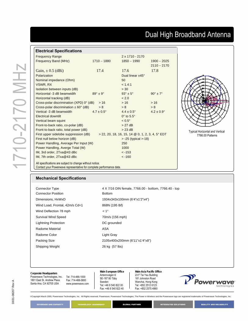
D03
1-08
207
Rev
A
Corporate HeadquartersPowerwave Technologies, Inc. 1801 East St. Andrew PlaceSanta Ana, CA 92705 USA
Tel: 714-466-1000Fax: 714-466-5800 www.powerwave.com
Main European OfficeAntennvägen 6SE-187 80 TäbySwedenTel: +46 8 540 822 00Fax: +46 8 540 823 40
©Copyright March 2005, Powerwave Technologies, Inc. All Rights reserved. Powerwave, Powerwave Technologies, The Power in Wireless and the Powerwave logo are registered trademarks of Powerwave Technologies, Inc.
Main Asia Pacific Office23 F Tai Yau Building181 Johnston RoadWanchai, Hong KongTel: +852 2512 6123Fax: +852 2575 4860
< 1°Wind Deflection 78 mph
26 kg (57 lbs)Shipping Weight
2105x400x200mm (6'11"x1’4"x8")Packing Size
Light GrayRadome Color
ASARadome Material
DC groundedLightning Protection
70m/s (156 mph) Survival Wind Speed
868N (195 lbf)Wind Load, Frontal, 42m/s Cd=1
1934x343x100mm (6’4”x1’2”x4”)Dimensions, HxWxD
BottomConnector Position4 X 7/16 DIN female, 7766.00 - bottom, 7766.40 - topConnector Type
Mechanical Specifications
Dual High Broadband Antenna17
10-2
170 M
HzFrequency Range Frequency Band (MHz)
Gain, ± 0.5 (dBi)Polarization Nominal impedance (Ohm)VSWR, RX Isolation between inputs (dB) Horizontal -3 dB beamwidthHorizontal tracking (dB)Cross-polar discrimination (XPD) 0° (dB)Cross-polar discrimination ± 60° (dB) Vertical -3 dB beamwidthElectrical downtiltVertical beam squintFront-to-back ratio, co-polar (dB)Front-to-back ratio, total power (dB) First upper sidelobe suppression (dB) First null below horizon (dB) Power Handling, Average Per Input (W)Power Handling, Averge Total (W)IM, 3rd order, 2Txa@43 dBc IM, 7th order, 2Txa@43 dBc
2 x 1710 - 2170 1710 – 1880 1850 – 1990 1900 – 2025
2110 – 2170 17.4 17.6 17.8
Dual linear ±45°50 < 1.4:1 > 30
89° ± 9° 93° ± 5° 90° ± 7°< 2.0
> 16 > 16 > 16 > 8 > 8 > 8
4.7 ± 0.5° 4.4 ± 0.5° 4.2 ± 0.9°0° to 5.5°< 0.5°> 27 dB> 23 dB
> 22, 20, 18, 16, 15, 14 @ 0, 1, 2, 3, 4, 5° EDT > -25 (typical >-18) 2501000 < -153< -160
Electrical Specifications
Typical Horizontal and Vertical 7766.00 Patterns
All specifications are subject to change without notice.Contact your Powerwave representative for complete performance data.
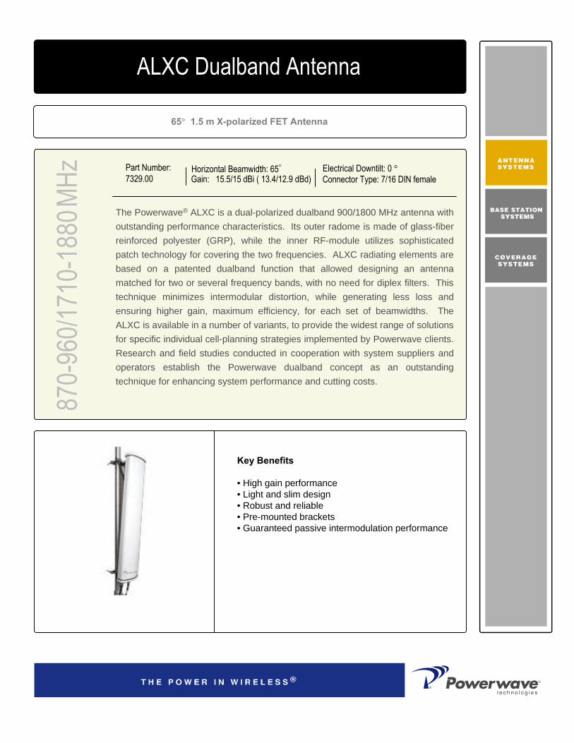
Part Number:7329.00
Horizontal Beamwidth: 65°
Gain: 15.5/15 dBi ( 13.4/12.9 dBd)Electrical Downtilt: 0 °Connector Type: 7/16 DIN female
870-
960/1
710-
1880
MHz
4168.11.33.00ALXC Dualband Antenna
65° 1.5 m X-polarized FET Antenna
The Powerwave® ALXC is a dual-polarized dualband 900/1800 MHz antenna with outstanding performance characteristics. Its outer radome is made of glass-fiber reinforced polyester (GRP), while the inner RF-module utilizes sophisticated patch technology for covering the two frequencies. ALXC radiating elements are based on a patented dualband function that allowed designing an antenna matched for two or several frequency bands, with no need for diplex filters. This technique minimizes intermodular distortion, while generating less loss and ensuring higher gain, maximum efficiency, for each set of beamwidths. The ALXC is available in a number of variants, to provide the widest range of solutions for specific individual cell-planning strategies implemented by Powerwave clients. Research and field studies conducted in cooperation with system suppliers and operators establish the Powerwave dualband concept as an outstanding technique for enhancing system performance and cutting costs.
Key Benefits
• High gain performance• Light and slim design• Robust and reliable• Pre-mounted brackets• Guaranteed passive intermodulation performance
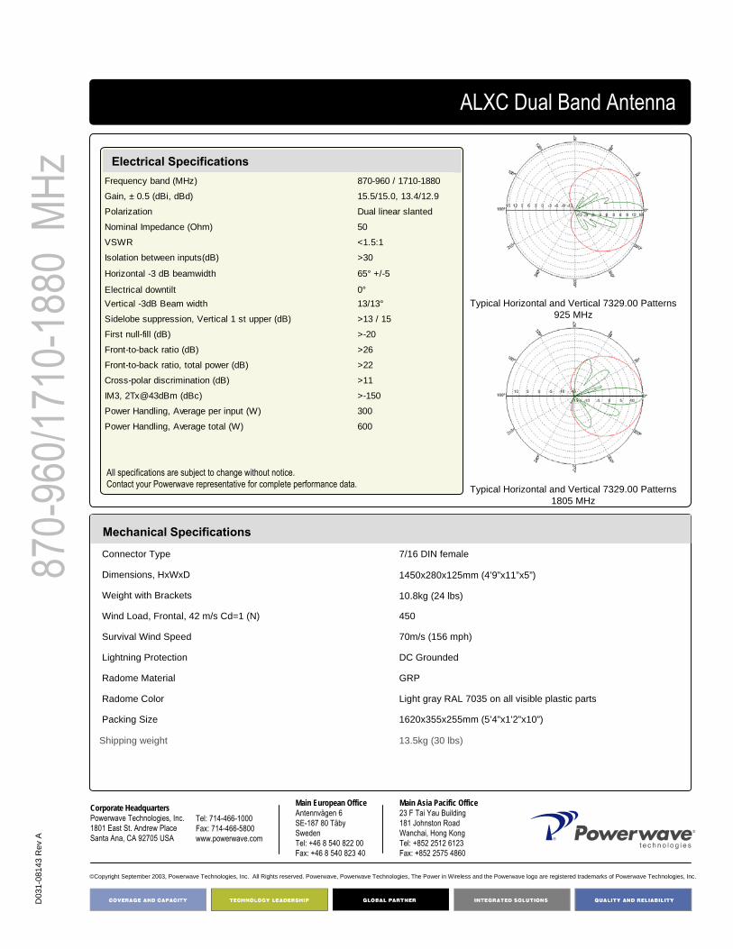
D03
1-08
143
Rev
A
©Copyright September 2003, Powerwave Technologies, Inc. All Rights reserved. Powerwave, Powerwave Technologies, The Power in Wireless and the Powerwave logo are registered trademarks of Powerwave Technologies, Inc.
Corporate HeadquartersPowerwave Technologies, Inc. 1801 East St. Andrew PlaceSanta Ana, CA 92705 USA
Tel: 714-466-1000Fax: 714-466-5800 www.powerwave.com
Main European OfficeAntennvägen 6SE-187 80 TäbySwedenTel: +46 8 540 822 00Fax: +46 8 540 823 40
Main Asia Pacific Office23 F Tai Yau Building181 Johnston RoadWanchai, Hong KongTel: +852 2512 6123Fax: +852 2575 4860
870-
960/1
710-
1880
MHz
13.5kg (30 lbs)Shipping weight
1620x355x255mm (5’4”x1’2”x10”)Packing Size
Light gray RAL 7035 on all visible plastic partsRadome Color
GRPRadome Material
DC GroundedLightning Protection
70m/s (156 mph)Survival Wind Speed
450Wind Load, Frontal, 42 m/s Cd=1 (N)
10.8kg (24 lbs)Weight with Brackets
1450x280x125mm (4’9”x11”x5”)Dimensions, HxWxD
7/16 DIN femaleConnector Type
Mechanical Specifications
Electrical SpecificationsFrequency band (MHz) 870-960 / 1710-1880
Gain, ± 0.5 (dBi, dBd) 15.5/15.0, 13.4/12.9
Polarization Dual linear slanted
Nominal Impedance (Ohm) 50
VSWR <1.5:1
Isolation between inputs(dB) >30
Horizontal -3 dB beamwidth 65° +/-5
Electrical downtilt 0°Vertical -3dB Beam width 13/13°
Sidelobe suppression, Vertical 1 st upper (dB) >13 / 15
First null-fill (dB) >-20
Front-to-back ratio (dB) >26
Front-to-back ratio, total power (dB) >22
Cross-polar discrimination (dB) >11
IM3, 2Tx@43dBm (dBc) >-150
Power Handling, Average per input (W) 300
Power Handling, Average total (W) 600
ALXC Dual Band Antenna
Typical Horizontal and Vertical 7329.00 Patterns 925 MHz
Typical Horizontal and Vertical 7329.00 Patterns 1805 MHz
All specifications are subject to change without notice.Contact your Powerwave representative for complete performance data.

Part Number:7329.06
Horizontal Beamwidth: 65°
Gain: 15.5/15 dBi ( 13.4/12.9 dBd)Electrical Downtilt: 6 °Connector Type: 7/16 DIN female
870-
960/1
710-
1880
MHz
4168.11.33.00ALXC Dualband Antenna
65° 1.5 m X-polarized FET Antenna
The Powerwave® ALXC is a dual-polarized dualband 900/1800 MHz antenna with outstanding performance characteristics. Its outer radome is made of glass-fiber reinforced polyester (GRP), while the inner RF-module utilizes sophisticated patch technology for covering the two frequencies. ALXC radiating elements are based on a patented dualband function that allowed designing an antenna matched for two or several frequency bands, with no need for diplex filters. This technique minimizes intermodular distortion, while generating less loss and ensuring higher gain, maximum efficiency, for each set of beamwidths. The ALXC is available in a number of variants, to provide the widest range of solutions for specific individual cell-planning strategies implemented by Powerwave clients. Research and field studies conducted in cooperation with system suppliers and operators establish the Powerwave dualband concept as an outstanding technique for enhancing system performance and cutting costs.
Key Benefits
• High gain performance• Light and slim design• Robust and reliable• Pre-mounted brackets• Guaranteed passive intermodulation performance

D03
1-08
143
Rev
A
©Copyright September 2003, Powerwave Technologies, Inc. All Rights reserved. Powerwave, Powerwave Technologies, The Power in Wireless and the Powerwave logo are registered trademarks of Powerwave Technologies, Inc.
Corporate HeadquartersPowerwave Technologies, Inc. 1801 East St. Andrew PlaceSanta Ana, CA 92705 USA
Tel: 714-466-1000Fax: 714-466-5800 www.powerwave.com
Main European OfficeAntennvägen 6SE-187 80 TäbySwedenTel: +46 8 540 822 00Fax: +46 8 540 823 40
Main Asia Pacific Office23 F Tai Yau Building181 Johnston RoadWanchai, Hong KongTel: +852 2512 6123Fax: +852 2575 4860
870-
960/1
710-
1880
MHz
13.5kg (30 lbs)Shipping weight
1620x355x255mm (5’4”x1’2”x10”)Packing Size
Light gray RAL 7035 on all visible plastic partsRadome Color
GRPRadome Material
DC GroundedLightning Protection
70m/s (156 mph)Survival Wind Speed
450Wind Load, Frontal, 42 m/s Cd=1 (N)
10.8kg (24 lbs)Weight with Brackets
1450x280x125mm (4’9”x11”x5”)Dimensions, HxWxD
7/16 DIN femaleConnector Type
Mechanical Specifications
Electrical SpecificationsFrequency band (MHz) 870-960 / 1710-1880
Gain, ± 0.5 (dBi, dBd) 15.5/15.0, 13.4/12.9
Polarization Dual linear slanted
Nominal Impedance (Ohm) 50
VSWR <1.5:1
Isolation between inputs(dB) >30
Horizontal -3 dB beamwidth 65° +/-5
Electrical downtilt 6°Vertical -3dB Beam width 13/13°
Sidelobe suppression, Vertical 1 st upper (dB) >13 / 15
First null-fill (dB) >-20
Front-to-back ratio (dB) >26
Front-to-back ratio, total power (dB) >22
Cross-polar discrimination (dB) >11
IM3, 2Tx@43dBm (dBc) >-150
Power Handling, Average per input (W) 300
Power Handling, Average total (W) 600
ALXC Dual Band Antenna
Typical Horizontal and Vertical 7329.00 Patterns 925 MHz
Typical Horizontal and Vertical 7329.00 Patterns 1805 MHz
All specifications are subject to change without notice.Contact your Powerwave representative for complete performance data.

Part Number:7330.00
Horizontal Beamwidth: 65°
Gain: 15.5/17.5 dBi (13.4/15.4 dBd)Electrical Downtilt: 0 °Connector Type: 7/16 DIN female
870-
960/1
710-
1880
MHz
4168.11.33.00ALXC Dualband Antenna
65° 1.5 m X-polarized FET Antenna
The Powerwave® ALXC is a dual-polarized dualband 900/1800 MHz antenna with outstanding performance characteristics. Its outer radome is made of glass-fiber reinforced polyester (GRP), while the inner RF-module utilizes sophisticated patch technology for covering the two frequencies. ALXC radiating elements are based on a patented dualband function that allowed designing an antenna matched for two or several frequency bands, with no need for diplex filters. This technique minimizes intermodular distortion, while generating less loss and ensuring higher gain, maximum efficiency, for each set of beamwidths. The ALXC is available in a number of variants, to provide the widest range of solutions for specific individual cell-planning strategies implemented by Powerwave clients. Research and field studies conducted in cooperation with system suppliers and operators establish the Powerwave dualband concept as an outstanding technique for enhancing system performance and cutting costs.
Key Benefits
• High gain performance• Light and slim design• Robust and reliable• Pre-mounted brackets• Guaranteed passive intermodulation performance

D03
1-08
144
Rev
A
©Copyright September 2003, Powerwave Technologies, Inc. All Rights reserved. Powerwave, Powerwave Technologies, The Power in Wireless and the Powerwave logo are registered trademarks of Powerwave Technologies, Inc.
Corporate HeadquartersPowerwave Technologies, Inc. 1801 East St. Andrew PlaceSanta Ana, CA 92705 USA
Tel: 714-466-1000Fax: 714-466-5800 www.powerwave.com
Main European OfficeAntennvägen 6SE-187 80 TäbySwedenTel: +46 8 540 822 00Fax: +46 8 540 823 40
Main Asia Pacific Office23 F Tai Yau Building181 Johnston RoadWanchai, Hong KongTel: +852 2512 6123Fax: +852 2575 4860
870-
960/1
710-
1880
MHz
13.5kg (30 lbs)Shipping weight
1620x355x255mm (5’4”x1’2”x10”)Packing Size
Light gray RAL 7035 on all visible plastic partsRadome Color
GRPRadome Material
DC GroundedLightning Protection
70m/s (156 mph)Survival Wind Speed
450Wind Load, Frontal, 42 m/s Cd=1 (N)
10.8kg (24 lbs)Weight with Brackets
1450x280x125mm (4’9”x11”x5”)Dimensions, HxWxD
7/16 DIN femaleConnector Type
Mechanical Specifications
Electrical SpecificationsFrequency band (MHz) 870-960 / 1710-1880
Gain, ± 0.5 (dBi, dBd) 15.5/17.5, 13.4/15.4
Polarization Dual linear slanted
Nominal Impedance (Ohm) 50
VSWR <1.5:1
Isolation between inputs(dB) >30
Horizontal tracking (dB) <2
Cross-polar discrimination (dB) >11 Horizontal -3 dB beamwidth 65° +/-5
Electrical downtilt 0°
Vertical -3dB Beam width 13/7°
Vertical beam squint <0.5°
Sidelobe suppression, Vertical 1 st upper (dB) >16
First null-fill (dB) >-20/-18
Front-to-back ratio (dB) >26
Front-to-back ratio, total power (dB) >22
IM3, 2Tx@43dBm (dBc) >-150
Power Handling, Average per input (W) 300Power Handling, Average total (W) 600
ALXC Dualband Antenna
Typical Horizontal and Vertical 7330.00 Patterns 925 MHz
Typical Horizontal and Vertical 7330.00 Patterns 1805 MHz
All specifications are subject to change without notice.Contact your Powerwave representative for complete performance data.
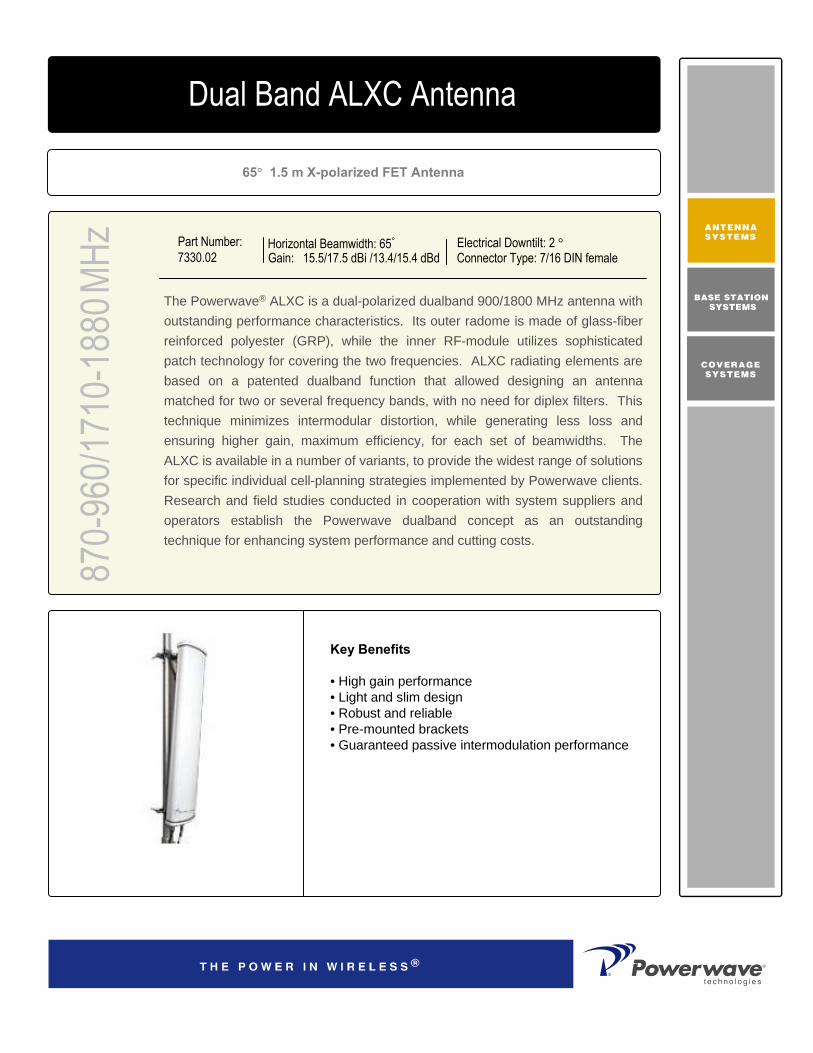
Part Number:7330.02
Horizontal Beamwidth: 65°
Gain: 15.5/17.5 dBi /13.4/15.4 dBdElectrical Downtilt: 2 °Connector Type: 7/16 DIN female
870-
960/1
710-
1880
MHz
4168.11.33.00Dual Band ALXC Antenna
65° 1.5 m X-polarized FET Antenna
The Powerwave® ALXC is a dual-polarized dualband 900/1800 MHz antenna with outstanding performance characteristics. Its outer radome is made of glass-fiber reinforced polyester (GRP), while the inner RF-module utilizes sophisticated patch technology for covering the two frequencies. ALXC radiating elements are based on a patented dualband function that allowed designing an antenna matched for two or several frequency bands, with no need for diplex filters. This technique minimizes intermodular distortion, while generating less loss and ensuring higher gain, maximum efficiency, for each set of beamwidths. The ALXC is available in a number of variants, to provide the widest range of solutions for specific individual cell-planning strategies implemented by Powerwave clients. Research and field studies conducted in cooperation with system suppliers and operators establish the Powerwave dualband concept as an outstanding technique for enhancing system performance and cutting costs.
Key Benefits
• High gain performance• Light and slim design• Robust and reliable• Pre-mounted brackets• Guaranteed passive intermodulation performance

D03
1-08
145
Rev
A
©Copyright September 2003, Powerwave Technologies, Inc. All Rights reserved. Powerwave, Powerwave Technologies, The Power in Wireless and the Powerwave logo are registered trademarks of Powerwave Technologies, Inc.
Corporate HeadquartersPowerwave Technologies, Inc. 1801 East St. Andrew PlaceSanta Ana, CA 92705 USA
Tel: 714-466-1000Fax: 714-466-5800 www.powerwave.com
Main European OfficeAntennvägen 6SE-187 80 TäbySwedenTel: +46 8 540 822 00Fax: +46 8 540 823 40
Main Asia Pacific Office23 F Tai Yau Building181 Johnston RoadWanchai, Hong KongTel: +852 2512 6123Fax: +852 2575 4860
870-
960/1
710-
1880
MHz
13.5kg (30 lbs)Shipping weight
1620x355x255mm (5’4”x1’2”x10”)Packing Size
Light gray RAL 7035 on all visible plastic partsRadome Color
GRPRadome Material
DC GroundedLightning Protection
70m/s (156 mph)Survival Wind Speed
450Wind Load, Frontal, 42 m/s Cd=1 (N)
10.8kg (24 lbs)Weight with Brackets
1450x280x125mm (4’9”x11”x5”)Dimensions, HxWxD
7/16 DIN femaleConnector Type
Mechanical Specifications
Electrical SpecificationsFrequency band (MHz) 870-960 / 1710-1880
Gain, ± 0.5 (dBi, dBd) 15.5/17.5, 13.4/15.4
Polarization Dual linear slanted
Nominal Impedance (Ohm) 50
VSWR <1.5:1
Isolation between inputs(dB) >30
Horizontal tracking (dB) <2
Cross-polar discrimination (dB) >11 Horizontal -3 dB beamwidth 65° +/-5
Electrical downtilt 2°
Vertical -3dB Beam width 13/7°
Vertical beam squint <0.5°
Sidelobe suppression, Vertical 1 st upper (dB) >16
First null-fill (dB) >-20/-18
Front-to-back ratio (dB) >26
Front-to-back ratio, total power (dB) >22
IM3, 2Tx@43dBm (dBc) >-150
Power Handling, Average per input (W) 300Power Handling, Average total (W) 600
Dual Band ALXC Antenna
Typical Horizontal and Vertical 7330.02 Patterns 925 MHz
Typical Horizontal and Vertical 7330.02 Patterns 1805 MHz
All specifications are subject to change without notice.Contact your Powerwave representative for complete performance data.
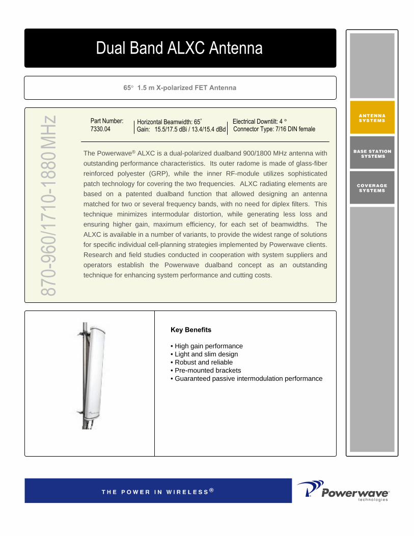
Part Number:7330.04
Horizontal Beamwidth: 65°
Gain: 15.5/17.5 dBi / 13.4/15.4 dBdElectrical Downtilt: 4 °Connector Type: 7/16 DIN female
870-
960/1
710-
1880
MHz
4168.11.33.00Dual Band ALXC Antenna
65° 1.5 m X-polarized FET Antenna
The Powerwave® ALXC is a dual-polarized dualband 900/1800 MHz antenna with outstanding performance characteristics. Its outer radome is made of glass-fiber reinforced polyester (GRP), while the inner RF-module utilizes sophisticated patch technology for covering the two frequencies. ALXC radiating elements are based on a patented dualband function that allowed designing an antenna matched for two or several frequency bands, with no need for diplex filters. This technique minimizes intermodular distortion, while generating less loss and ensuring higher gain, maximum efficiency, for each set of beamwidths. The ALXC is available in a number of variants, to provide the widest range of solutions for specific individual cell-planning strategies implemented by Powerwave clients. Research and field studies conducted in cooperation with system suppliers and operators establish the Powerwave dualband concept as an outstanding technique for enhancing system performance and cutting costs.
Key Benefits
• High gain performance• Light and slim design• Robust and reliable• Pre-mounted brackets• Guaranteed passive intermodulation performance

D)3
1-08
146
Rev
A
©Copyright September 2003, Powerwave Technologies, Inc. All Rights reserved. Powerwave, Powerwave Technologies, The Power in Wireless and the Powerwave logo are registered trademarks of Powerwave Technologies, Inc.
Corporate HeadquartersPowerwave Technologies, Inc. 1801 East St. Andrew PlaceSanta Ana, CA 92705 USA
Tel: 714-466-1000Fax: 714-466-5800 www.powerwave.com
Main European OfficeAntennvägen 6SE-187 80 TäbySwedenTel: +46 8 540 822 00Fax: +46 8 540 823 40
Main Asia Pacific Office23 F Tai Yau Building181 Johnston RoadWanchai, Hong KongTel: +852 2512 6123Fax: +852 2575 4860
870-
960/1
710-
1880
MHz
13.5kg (30 lbs)Shipping weight
1620x355x255mm (5’4”x1’2”x10”)Packing Size
Light gray RAL 7035 on all visible plastic partsRadome Color
GRPRadome Material
DC GroundedLightning Protection
70m/s (156 mph)Survival Wind Speed
450Wind Load, Frontal, 42 m/s Cd=1 (N)
10.8kg (24 lbs)Weight with Brackets
1450x280x125mm (4’9”x11”x5”)Dimensions, HxWxD
7/16 DIN femaleConnector Type
Mechanical Specifications
Electrical SpecificationsFrequency band (MHz) 870-960 / 1710-1880
Gain, ± 0.5 (dBi, dBd) 15.5/17.5, 13.4/15.4
Polarization Dual linear slanted
Nominal Impedance (Ohm) 50
VSWR <1.5:1
Isolation between inputs(dB) >30
Horizontal tracking (dB) <2
Cross-polar discrimination (dB) >11 Horizontal -3 dB beamwidth 65° +/-5
Electrical downtilt 4°
Vertical -3dB Beam width 13/7°
Vertical beam squint <0.5°
Sidelobe suppression, Vertical 1 st upper (dB) >16
First null-fill (dB) >-20/-18
Front-to-back ratio (dB) >26
Front-to-back ratio, total power (dB) >22
IM3, 2Tx@43dBm (dBc) >-150
Power Handling, Average per input (W) 300Power Handling, Average total (W) 600
ALXC Dualband Antenna
Typical Horizontal and Vertical 7330.04 Patterns 925 MHz
Typical Horizontal and Vertical 7330.04 Patterns 1805 MHz
All specifications are subject to change without notice.Contact your Powerwave representative for complete performance data.

Part Number:7330.06
Horizontal Beamwidth: 65°
Gain: 15.5/17.5 dBi / 13.4/15.4 dBdElectrical Downtilt: 6 °Connector Type: 7/16 DIN female
870-
960/1
710-
1880
MHz
4168.11.33.00Dual Band ALXC Antenna65° 1.5 m X-polarized FET Antenna
The Powerwave® ALXC is a dual-polarized dualband 900/1800 MHz antenna with outstanding performance characteristics. Its outer radome is made of glass-fiber reinforced polyester (GRP), while the inner RF-module utilizes sophisticated patch technology for covering the two frequencies. ALXC radiating elements are based on a patented dualband function that allowed designing an antenna matched for two or several frequency bands, with no need for diplex filters. This technique minimizes intermodular distortion, while generating less loss and ensuring higher gain, maximum efficiency, for each set of beamwidths. The ALXC is available in a number of variants, to provide the widest range of solutions for specific individual cell-planning strategies implemented by Powerwave clients. Research and field studies conducted in cooperation with system suppliers and operators establish the Powerwave dualband concept as an outstanding technique for enhancing system performance and cutting costs.
Key Benefits
• High gain performance• Light and slim design• Robust and reliable• Pre-mounted brackets• Guaranteed passive intermodulation performance

D03
1-08
147
Rev
A
©Copyright September 2003, Powerwave Technologies, Inc. All Rights reserved. Powerwave, Powerwave Technologies, The Power in Wireless and the Powerwave logo are registered trademarks of Powerwave Technologies, Inc.
Corporate HeadquartersPowerwave Technologies, Inc. 1801 East St. Andrew PlaceSanta Ana, CA 92705 USA
Tel: 714-466-1000Fax: 714-466-5800 www.powerwave.com
Main European OfficeAntennvägen 6SE-187 80 TäbySwedenTel: +46 8 540 822 00Fax: +46 8 540 823 40
Main Asia Pacific Office23 F Tai Yau Building181 Johnston RoadWanchai, Hong KongTel: +852 2512 6123Fax: +852 2575 4860
870-
960/1
710-
1880
MHz
13.5kg (30 lbs)Shipping weight
1620x355x255mm (5’4”x1’2”x10”)Packing Size
Light gray RAL 7035 on all visible plastic partsRadome Color
GRPRadome Material
DC GroundedLightning Protection
70m/s (156 mph)Survival Wind Speed
450Wind Load, Frontal, 42 m/s Cd=1 (N)
10.8kg (24 lbs)Weight with Brackets
1450x280x125mm (4’9”x11”x5”)Dimensions, HxWxD
7/16 DIN femaleConnector Type
Mechanical Specifications
Electrical SpecificationsFrequency band (MHz) 870-960 / 1710-1880
Gain, ± 0.5 (dBi, dBd) 15.5/17.5, 13.4/15.4
Polarization Dual linear slanted
Nominal Impedance (Ohm) 50
VSWR <1.5:1
Isolation between inputs(dB) >30
Horizontal tracking (dB) <2
Cross-polar discrimination (dB) >11 Horizontal -3 dB beamwidth 65° +/-5
Electrical downtilt 6°
Vertical -3dB Beam width 13/7°
Vertical beam squint <0.5°
Sidelobe suppression, Vertical 1 st upper (dB) >16
First null-fill (dB) >-20/-18
Front-to-back ratio (dB) >26
Front-to-back ratio, total power (dB) >22
IM3, 2Tx@43dBm (dBc) >-150
Power Handling, Average per input (W) 300Power Handling, Average total (W) 600
Dual Band ALXC Antenna
Typical Horizontal and Vertical 7330.06 Patterns 925 MHz
Typical Horizontal and Vertical 7330.06 Patterns 1805 MHz
All specifications are subject to change without notice.Contact your Powerwave representative for complete performance data.

Part Number:7331.00
Horizontal Beamwidth: 65°
Gain: 16.5/16 dBi / 14.4/13.9 dBdElectrical Downtilt: 0 °Connector Type: 7/16 DIN female
870-
960/1
710-
1880
MHz
4168.11.33.00Dual Band ALXC Antenna65° 2.0 m X-polarized FET Antenna
The Powerwave® ALXC is a dual-polarized dualband 900/1800 MHz antenna with outstanding performance characteristics. Its outer radome is made of glass-fiber reinforced polyester (GRP), while the inner RF-module utilizes sophisticated patch technology for covering the two frequencies. ALXC radiating elements are based on a patented dualband function that allowed designing an antenna matched for two or several frequency bands, with no need for diplex filters. This technique minimizes intermodular distortion, while generating less loss and ensuring higher gain, maximum efficiency, for each set of beamwidths. The ALXC is available in a number of variants, to provide the widest range of solutions for specific individual cell-planning strategies implemented by Powerwave clients. Research and field studies conducted in cooperation with system suppliers and operators establish the Powerwave dualband concept as an outstanding technique for enhancing system performance and cutting costs.
Key Benefits
• High gain performance• Light and slim design• Robust and reliable• Pre-mounted brackets• Guaranteed passive intermodulation performance

D03
1-08
148
Rev
A
©Copyright September 2003, Powerwave Technologies, Inc. All Rights reserved. Powerwave, Powerwave Technologies, The Power in Wireless and the Powerwave logo are registered trademarks of Powerwave Technologies, Inc.
Corporate HeadquartersPowerwave Technologies, Inc. 1801 East St. Andrew PlaceSanta Ana, CA 92705 USA
Tel: 714-466-1000Fax: 714-466-5800 www.powerwave.com
Main European OfficeAntennvägen 6SE-187 80 TäbySwedenTel: +46 8 540 822 00Fax: +46 8 540 823 40
Main Asia Pacific Office23 F Tai Yau Building181 Johnston RoadWanchai, Hong KongTel: +852 2512 6123Fax: +852 2575 4860
870-
960/1
710-
1880
MHz
16.5kg (36.4 lbs)Shipping weight
2160x355x255mm (7’1”x1’2”x10”)Packing Size
Light gray RAL 7035 on all visible plastic partsRadome Color
GRPRadome Material
DC GroundedLightning Protection
70m/s (156 mph)Survival Wind Speed
610Wind Load, Frontal, 42 m/s Cd=1 (N)
13.5kg (30 lbs) Weight with Brackets
1990x280x125mm (6’6”x11”x5”)Dimensions, HxWxD
7/16 DIN femaleConnector Type
Mechanical Specifications
Electrical SpecificationsFrequency band (MHz) 870-960 / 1710-1880
Gain, ± 0.5 (dBi, dBd) 16.5/16 14.4/13.9
Polarization Dual linear slanted
Nominal Impedance (Ohm) 50
VSWR <1.5:1
Isolation between inputs(dB) >30
Horizontal tracking (dB) <2
Cross-polar discrimination (dB) >11 Horizontal -3 dB beamwidth 65° +/-5
Electrical downtilt 0°
Vertical -3dB Beam width 9°/9°
Vertical beam squint <0.5°
Sidelobe suppression, Vertical 1 st upper (dB) >16
First null-fill (dB) >-22/-22
Front-to-back ratio (dB) >25
Front-to-back ratio, total power (dB) >21
IM3, 2Tx@43dBm (dBc) >-150
Power Handling, Average per input (W) 300Power Handling, Average total (W) 600
Dual Band ALXC Antenna
Typical Horizontal and Vertical 7331.00 Patterns 925 MHz
Typical Horizontal and Vertical 7331.00 Patterns 1805 MHz
All specifications are subject to change without notice.Contact your Powerwave representative for complete performance data.

Part Number:7331.02
Horizontal Beamwidth: 65°Gain: 16.5/16 dBi / 14.4/13.9 dBd
Electrical Downtilt: 2°Connector Type: 7/16 DIN female
870-
960/1
710-
1880
MHz
4168.11.33.00Dual Band ALXC Antenna65° 2.0 m X-polarized FET Antenna
The Powerwave® ALXC is a dual-polarized dualband 900/1800 MHz antenna with outstanding performance characteristics. Its outer radome is made of glass-fiber reinforced polyester (GRP), while the inner RF-module utilizes sophisticated patch technology for covering the two frequencies. ALXC radiating elements are based on a patented dualband function that allowed designing an antenna matched for two or several frequency bands, with no need for diplex filters. This technique minimizes intermodular distortion, while generating less loss and ensuring higher gain, maximum efficiency, for each set of beamwidths. The ALXC is available in a number of variants, to provide the widest range of solutions for specific individual cell-planning strategies implemented by Powerwave clients. Research and field studies conducted in cooperation with system suppliers and operators establish the Powerwave dualband concept as an outstanding technique for enhancing system performance and cutting costs.
Key Benefits
• High gain performance• Light and slim design• Robust and reliable• Pre-mounted brackets• Guaranteed passive intermodulation performance

D03
1-08
149
Rev
A
©Copyright September 2003, Powerwave Technologies, Inc. All Rights reserved. Powerwave, Powerwave Technologies, The Power in Wireless and the Powerwave logo are registered trademarks of Powerwave Technologies, Inc.
Corporate HeadquartersPowerwave Technologies, Inc. 1801 East St. Andrew PlaceSanta Ana, CA 92705 USA
Tel: 714-466-1000Fax: 714-466-5800 www.powerwave.com
Main European OfficeAntennvägen 6SE-187 80 TäbySwedenTel: +46 8 540 822 00Fax: +46 8 540 823 40
Main Asia Pacific Office23 F Tai Yau Building181 Johnston RoadWanchai, Hong KongTel: +852 2512 6123Fax: +852 2575 4860
870-
960/1
710-
1880
MHz
16.5kg (36.4 lbs)Shipping weight
2160x355x255mm (7’1”x1’2”x10”)Packing Size
Light gray RAL 7035 on all visible plastic partsRadome Color
GRPRadome Material
DC GroundedLightning Protection
70m/s (156 mph)Survival Wind Speed
610Wind Load, Frontal, 42 m/s Cd=1 (N)
13.5kg (30 lbs) Weight with Brackets
1990x280x125mm (6’6”x11”x5”)Dimensions, HxWxD
7/16 DIN femaleConnector Type
Mechanical Specifications
Electrical SpecificationsFrequency band (MHz) 870-960 / 1710-1880
Gain, ± 0.5 (dBi, dBd) 16.5/16 14.4/13.9
Polarization Dual linear slanted
Nominal Impedance (Ohm) 50
VSWR <1.5:1
Isolation between inputs(dB) >30
Horizontal tracking (dB) <2
Cross-polar discrimination (dB) >11 Horizontal -3 dB beamwidth 65° +/-5
Electrical downtilt 2°
Vertical -3dB Beam width 9°/9°
Vertical beam squint <0.5°
Sidelobe suppression, Vertical 1 st upper (dB) >16
First null-fill (dB) >-22/-22
Front-to-back ratio (dB) >25
Front-to-back ratio, total power (dB) >21
IM3, 2Tx@43dBm (dBc) >-150
Power Handling, Average per input (W) 300Power Handling, Average total (W) 600
Dual Band ALXC Antenna
Typical Horizontal and Vertical 7331.02 Patterns 925 MHz
Typical Horizontal and Vertical 7331.02 Patterns 1805 MHz
All specifications are subject to change without notice.Contact your Powerwave representative for complete performance data.

Part Number:7331.04
Horizontal Beamwidth: 65°Gain: 16.5/16 dBi / 14.4/13.9 dBd
Electrical Downtilt: 4°Connector Type: 7/16 DIN female
870-
960/1
710-
1880
MHz
4168.11.33.00Dual Band ALXC Antenna65° 2.0 m X-polarized FET Antenna
The Powerwave® ALXC is a dual-polarized dual band 900/1800 MHz antenna with outstanding performance characteristics. Its outer radome is made of glass-fiber reinforced polyester (GRP), while the inner RF-module utilizes sophisticated patch technology for covering the two frequencies. ALXC radiating elements are based on a patented dual band function that allowed designing an antenna matched for two or several frequency bands, with no need for diplex filters. This technique minimizes intermodular distortion, while generating less loss and ensuring higher gain, maximum efficiency, for each set of beamwidths. The ALXC is available in a number of variants, to provide the widest range of solutions for specific individual cell-planning strategies implemented by Powerwave clients. Research and field studies conducted in cooperation with system suppliers and operators establish the Powerwave dual band concept as an outstanding technique for enhancing system performance and cutting costs.
Key Benefits
• High gain performance• Light and slim design• Robust and reliable• Pre-mounted brackets• Guaranteed passive intermodulation performance

D03
1-08
150
Rev
A
©Copyright September 2003, Powerwave Technologies, Inc. All Rights reserved. Powerwave, Powerwave Technologies, The Power in Wireless and the Powerwave logo are registered trademarks of Powerwave Technologies, Inc.
Corporate HeadquartersPowerwave Technologies, Inc. 1801 East St. Andrew PlaceSanta Ana, CA 92705 USA
Tel: 714-466-1000Fax: 714-466-5800 www.powerwave.com
Main European OfficeAntennvägen 6SE-187 80 TäbySwedenTel: +46 8 540 822 00Fax: +46 8 540 823 40
Main Asia Pacific Office23 F Tai Yau Building181 Johnston RoadWanchai, Hong KongTel: +852 2512 6123Fax: +852 2575 4860
870-
960/1
710-
1880
MHz
16.5kg (36.4 lbs)Shipping weight
2160x355x255mm (7’1”x1’2”x10”)Packing Size
Light gray RAL 7035 on all visible plastic partsRadome Color
GRPRadome Material
DC GroundedLightning Protection
70m/s (156 mph)Survival Wind Speed
610Wind Load, Frontal, 42 m/s Cd=1 (N)
13.5kg (30 lbs) Weight with Brackets
1990x280x125mm (6’6”x11”x5”)Dimensions, HxWxD
7/16 DIN femaleConnector Type
Mechanical Specifications
Electrical SpecificationsFrequency band (MHz) 870-960 / 1710-1880
Gain, ± 0.5 (dBi, dBd) 16.5/16 14.4/13.9
Polarization Dual linear slanted
Nominal Impedance (Ohm) 50
VSWR <1.5:1
Isolation between inputs(dB) >30
Horizontal tracking (dB) <2
Cross-polar discrimination (dB) >11 Horizontal -3 dB beamwidth 65° +/-5
Electrical downtilt 4°
Vertical -3dB Beam width 9°/9°
Vertical beam squint <0.5°
Sidelobe suppression, Vertical 1 st upper (dB) >16
First null-fill (dB) >-22/-22
Front-to-back ratio (dB) >25
Front-to-back ratio, total power (dB) >21
IM3, 2Tx@43dBm (dBc) >-150
Power Handling, Average per input (W) 300Power Handling, Average total (W) 600
Dual Band ALXC Antenna
Typical Horizontal and Vertical 7331.04 Patterns 925 MHz
Typical Horizontal and Vertical 7331.04 Patterns 1805 MHz
All specifications are subject to change without notice.Contact your Powerwave representative for complete performance data.

Part Number:7331.06
Horizontal Beamwidth: 65°
Gain: 16.5/16 dBi/14.4/13.9 dBdElectrical Downtilt: 6°Connector Type: 7/16 DIN female
870-
960/1
710-
1880
MHz
4168.11.33.00Dual Band ALXC Antenna65° 2.0 m X-polarized FET Antenna
The Powerwave® ALXC is a dual-polarized dual band 900/1800 MHz antenna with outstanding performance characteristics. Its outer radome is made of glass-fiber reinforced polyester (GRP), while the inner RF-module utilizes sophisticated patch technology for covering the two frequencies. ALXC radiating elements are based on a patented dual band function that allowed designing an antenna matched for two or several frequency bands, with no need for diplex filters. This technique minimizes intermodular distortion, while generating less loss and ensuring higher gain, maximum efficiency, for each set of beamwidths. The ALXC is available in a number of variants, to provide the widest range of solutions for specific individual cell-planning strategies implemented by Powerwave clients. Research and field studies conducted in cooperation with system suppliers and operators establish the Powerwave dual band concept as an outstanding technique for enhancing system performance and cutting costs.
Key Benefits
• High gain performance• Light and slim design• Robust and reliable• Pre-mounted brackets• Guaranteed passive intermodulation performance

D03
1-08
151
Rev
A
©Copyright September 2003, Powerwave Technologies, Inc. All Rights reserved. Powerwave, Powerwave Technologies, The Power in Wireless and the Powerwave logo are registered trademarks of Powerwave Technologies, Inc.
Corporate HeadquartersPowerwave Technologies, Inc. 1801 East St. Andrew PlaceSanta Ana, CA 92705 USA
Tel: 714-466-1000Fax: 714-466-5800 www.powerwave.com
Main European OfficeAntennvägen 6SE-187 80 TäbySwedenTel: +46 8 540 822 00Fax: +46 8 540 823 40
Main Asia Pacific Office23 F Tai Yau Building181 Johnston RoadWanchai, Hong KongTel: +852 2512 6123Fax: +852 2575 4860
870-
960/1
710-
1880
MHz
16.5kg (36.4 lbs)Shipping weight
2160x355x255mm (7’1”x1’2”x10”)Packing Size
Light gray RAL 7035 on all visible plastic partsRadome Color
GRPRadome Material
DC GroundedLightning Protection
70m/s (156 mph)Survival Wind Speed
610Wind Load, Frontal, 42 m/s Cd=1 (N)
13.5kg (30 lbs) Weight with Brackets
1990x280x125mm (6’6”x11”x5”)Dimensions, HxWxD
7/16 DIN femaleConnector Type
Mechanical Specifications
Electrical SpecificationsFrequency band (MHz) 870-960 / 1710-1880
Gain, ± 0.5 (dBi, dBd) 16.5/16 14.4/13.9
Polarization Dual linear slanted
Nominal Impedance (Ohm) 50
VSWR <1.5:1
Isolation between inputs(dB) >30
Horizontal tracking (dB) <2
Cross-polar discrimination (dB) >11 Horizontal -3 dB beamwidth 65° +/-5
Electrical downtilt 6°
Vertical -3dB Beam width 9°/9°
Vertical beam squint <0.5°
Sidelobe suppression, Vertical 1 st upper (dB) >16
First null-fill (dB) >-22/-22
Front-to-back ratio (dB) >25
Front-to-back ratio, total power (dB) >21
IM3, 2Tx@43dBm (dBc) >-150
Power Handling, Average per input (W) 300Power Handling, Average total (W) 600
Dual Band ALXC Antenna
Typical Horizontal and Vertical 7331.06 Patterns 925 MHz
Typical Horizontal and Vertical 7331.06 Patterns 1805 MHz
All specifications are subject to change without notice.Contact your Powerwave representative for complete performance data.

65° 1.4 m X-polarized MET Antenna
Part Number:7750.x0
Horizontal Beamwidth: 650
Gain: 14.2/17.5 dBi/12.1/15.4 dBd Electrical Downtilt: AdjustableConnector Type: 7/16 DIN female
The Powerwave broadband antenna design is based on a patented stacked aperture-coupled patch technology, which provides high isolation performance and a wide VSWR bandwidth. The antennas have superior radiation patterns due to a unique reflector design that provides a very small variation of the -3dB horizontal beam width over the frequency band as well as a high front-to-back ratio. Powerwave broadband antennas come with manually adjustable electrical tilt (MET) for tuning flexibility of tilt angles. This design ensures the highest possible cross-polar discrimination value.Available with Powerwave’s pre-mounted RET solution and upgradeable in field.
824-
960/1
710-
2170
MHz
4168.11.33.00Dual Broadband Antenna
Key Benefits
• Excellent broad- and multi-band capabilities • Polarization purity maximizes diversity gain• Excellent pattern performance and high gain over
frequency• Guaranteed passive intermodulation performance• Light, slim and robust design

D03
1-08
201
Rev
A
Corporate HeadquartersPowerwave Technologies, Inc. 1801 East St. Andrew PlaceSanta Ana, CA 92705 USA
Tel: 714-466-1000Fax: 714-466-5800 www.powerwave.com
Main European OfficeAntennvägen 6SE-187 80 TäbySwedenTel: +46 8 540 822 00Fax: +46 8 540 823 40
Main Asia Pacific Office23 F Tai Yau Building181 Johnston RoadWanchai, Hong KongTel: +852 2512 6123Fax: +852 2575 4860
©Copyright September 2003, Powerwave Technologies, Inc. All Rights reserved. Powerwave, Powerwave Technologies, The Power in Wireless and the Powerwave logo are registered trademarks of Powerwave Technologies, Inc.
70m/s (156 mph)Survival Wind SpeedDC groundedLightning ProtectionGRPRadome Material
Radome Color
1550mm x 355mm x 255mm (61”x14”x10”)Packing Size
15.8 kg (35 lbs)Weight Including Brackets435N (98 lbf)Wind Load, Frontal, 42m/s Cd=1
1408mm x 280mm x 125mm (4’7”x11”x5”)Dimensions, HxWxD
BottomConnector Position
7/16 DIN female, 7750.00 - bottom, 7750.40 - topConnector Type
Dual Broadband Antenna82
4-96
0/171
0-21
70 M
Hz
Mechanical Specifications
Pre-mounted Standard BracketsMounting
Typical 800 MHz Horizontal and Vertical
Typical 1900 MHz Horizontal and Vertical
Electrical Specifications
Grey (RAL 7035 on all visible plastic part)
Frequency band (MHz) 824-960 1710-2170Gain, ± 0.5dB (dBi)/(dBd) 14.2/12.1 17.5/15.4Polarization Dual linear ±45°Nominal Impedance (Ohm) 50VSWR 1.5:1VSWR 1.5:1Isolation between inputs (dB) 30Isolation between inputs (dB) 30Inter band isolation (dB) 40Horizontal -3 dB beamwidth 69 ± 6° 63 ± 7°Tracking, Horizontal plane, ±60° (dB) <1.0Tracking, Horizontal plane, ±60° (dB) <2.0Electrical downtilt range (adjustable) 2° to 12° 0° to 8°Vertical -3 dB beamwidth 14.3 ± 2.0° 6.6 ± 1°Sidelobe suppression, Vertical 1 st upper (dB)
> 18,17,16,16,15,15 > 18,18,16,15,14 x=2, 4, 6, 8,10,12° MET x=0, 2, 4, 6, 8° MET
Vertical beam squint 1.5° 0.8°First null-fill (dB) <-25 <-25Front-to-back ratio (dB) >27 >27Front-to-back ratio, total power (dB) >24 >24IM3, @2x43dBm (dBc) <-153IM3, @2x43dBm (dBc) <-153Average IM7, 2Tx@43dBm (dBc) <-160Power Handling, Average per input (W) 300 250Power Handling, Average total (W) 600 500
All specifications are subject to change without notice. Contact factory for complete performance data.

65° 2.0 m X-polarized MET Antenna
Part Number:7752.x0
Horizontal Beamwidth: 65°
Gain: 15.9/17.5 dBiElectrical Downtilt: AdjustableConnector Type: 7/16 DIN female
The Powerwave dual band dual polarized broadband antenna has individual adjustable electrical downtilt per band. Four connector ports allow separate tilts on each frequency band and ensure the use of diversity concepts. The phase shifter technology, based on a patented sliding dielectric, minimizes intermodulation distortion and maximizes efficiency. The slant +/- 45° dual polarization system provides the independent fading signals needed for achieving top-quality coverage via diversity concepts. The Powerwave Broadband antenna design is based on a patented stacked aperture-coupled patch technology, which provides high isolation performance and a wide VSWR bandwidth. The antennas have superior radiation patterns due to a unique reflector design which provides a very small variation of the –3dB horizontal beam width over the frequency band as well as a high front-to-back ratio.
824-
960/1
710-
2170
MHz
Dual Broadband Antenna
Key Benefits
• Excellent broad- and multi-band capabilities • Polarization purity makes good diversity gain• Excellent pattern performance and high gain over
frequency• High passive intermodulation performance• Light, slim and robust design

D03
1-08
202
Rev
A
Corporate HeadquartersPowerwave Technologies, Inc. 1801 East St. Andrew PlaceSanta Ana, CA 92705 USA
Tel: 714-466-1000Fax: 714-466-5800 www.powerwave.com
Main European OfficeAntennvägen 6SE-187 80 TäbySwedenTel: +46 8 540 822 00Fax: +46 8 540 823 40
©Copyright March 2005, Powerwave Technologies, Inc. All Rights reserved. Powerwave, Powerwave Technologies, The Power in Wireless and the Powerwave logo are registered trademarks of Powerwave Technologies, Inc.
Main Asia Pacific Office23 F Tai Yau Building181 Johnston RoadWanchai, Hong KongTel: +852 2512 6123Fax: +852 2575 4860
2175mm x 355mm x 255mm (7‘4"x14"x10")Packing SizeLight GrayRadome ColorGRPRadome MaterialDC groundedLightning Protection70m/s (156mph)Survival Wind Speed628N (141lbf) Wind Load, Frontal, 42m/s Cd=1
2033mm x 280mm x 125mm (6’7” x 11”x 5”)19.7kg (44lbs) 16kg (35lbs)
Dimensions, HxWxDWeight Including BracketsWeigh Excluding Brackets
BottomConnector Position
7/16 DIN female, 7752.00 - bottom, 7752.40 - topConnector Type
824-
960/1
710-
2170
MHz
Dual Broadband Antenna
Frequency band (MHz) 824-960 1710-2170Gain, ± 0.5 (dBi) 15.9 17.5Polarization Dual linear ±45°Nominal Impedance (OHM) 50VSWR, 824-960MHz 1.5:1VSWR, 1710-2170MHz 1.5:1Isolation between inputs, 824-960MHz (dB) 30Isolation between inputs, 1710-2170MHz (dB) 30Inter band isolation, MHz (dB) 40Horizontal -3 dB beamwidth 69 ± 6° 63 ± 7 °Tracking,Horizontal plane, 824-960MHz, ±60° (dB) <1.0Tracking,Horizontal plane, 1710-2170MHz, ±60° (dB) <2.0Electrical downtilt range (adjustable) 2° to 9° 0° to 8°Vertical -3 dB beamwidth 9.2 ± 1.0° 6.6 ±1.0°Sidelobe suppression, Vertical 1 st upper (dB) > 17,16,15,14 > 17,16,15,14,13 dB
x=2, 4, 6, 8° MET x=0, 2, 4, 6, 8° METVertical beam squint 0.8° 0.8°First null-fill (dB) < -25 < -25Front-to-back ratio (dB) >27 >27Front-to-back ratio, total power (dB) >24 >24Average IM3, 2Tx@43dBm (dBc) < -153Average IM3, 2Tx@43dBm (dBc) < -153Average IM7, 2Tx@43dBm (dBc) < -160Power Handling, Average per input (W) 300 250Power Handling, Average total (W) 600 500
Electrical Specifications
Mechanical Specifications
Typical 800 MHz Horizontal and Vertical7752.00 Patterns
Typical 1900 MHz Horizontal and Vertical7752.00 Patterns
All specifications are subject to change without notice.Contact your Powerwave representative for complete performance data.

65° 2.6 m X-polarized MET Antenna
Part Number:7755.x0
Horizontal Beamwidth: 65o
Gain: 17.5/ 17.5dBiElectrical Downtilt: AdjustableConnector Type: 7/16 DIN female
The Powerwave dual band dual polarized broadband antenna has individual adjustable electrical downtilt per band. Four connector ports allow separate tilts on each frequency band and ensure the use of diversity concepts. The phase shifter technology, based on a patented sliding dielectric, minimizes intermodulation distortion and maximizes efficiency. The slant +/- 45° dual polarization system provides the independent fading signals needed for achieving top-quality coverage via diversity concepts. The Powerwave Broadband antenna design is based on a patented stacked aperture-coupled patch technology, which provides high isolation performance and a wide VSWR bandwidth. The antennas have superior radiation patterns due to a unique reflector design which provides a very small variation of the –3dB horizontal beam width over the frequency band as well as a high front-to-back ratio.
824-
960/1
710-
2170
MHz
4168.11.33.00 Dual Broadband Antenna
Key Benefits
• Excellent broad- and multi-band capabilities • Polarization purity makes good diversity gain• Excellent pattern performance and high gain over
frequency• High passive intermodulation performance• Light, slim and robust design

D03
1-08
203
Rev
A
Corporate HeadquartersPowerwave Technologies, Inc. 1801 East St. Andrew PlaceSanta Ana, CA 92705 USA
Tel: 714-466-1000Fax: 714-466-5800 www.powerwave.com
Main European OfficeAntennvägen 6SE-187 80 TäbySwedenTel: +46 8 540 822 00Fax: +46 8 540 823 40
©Copyright March 2005, Powerwave Technologies, Inc. All Rights reserved. Powerwave, Powerwave Technologies, The Power in Wireless and the Powerwave logo are registered trademarks of Powerwave Technologies, Inc.
Main Asia Pacific Office23 F Tai Yau Building181 Johnston RoadWanchai, Hong KongTel: +852 2512 6123Fax: +852 2575 4860
19.6 kg (43 lbs) Weight With Brackets
23.3 kg (52 lbs)Shipping Weight2830x355x255mm (9‘4"x1’2"x10")Packing SizeLight GrayRadome ColorPVCRadome MaterialDC groundedLightning Protection70m/s (156 mph)Survival Wind Speed
868N (195 lbf)Wind Load, Frontal, 100 mph Cd=1 (N)2630x280x125mm (8‘8"x11“x5”)Dimensions, HxWxDBottomConnector Position
7/16 DIN female, 7755.00 - bottom, 7755.40 - topConnector Type
Dual Broadband Antenna82
4-96
0 / 17
10-2
170 M
HzElectrical SpecificationsFrequency band (MHz) 824-960 1710-2170
Gain, ± 0.5 (dBi) 17.5 17.5Polarization Dual linear ±45°Nominal Impedance (Ohm) 50VSWR, 824-960MHz 1.5:1VSWR, 1710-2170MHz 1.5:1Isolation between inputs, 824-960MHz (dB) 30Isolation between inputs, 1710-2170MHz (dB) 30Inter band isolation, MHz (dB) 38Horizontal -3 dB beamwidth 65° 65°Tracking,Horizontal plane, 824-960MHz, ±60° <2.0dBTracking,Horizontal plane, 1710-2170MHz, ±60° <1.5dBElectrical downtilt range (adjustable) 2° to 8° 0° to 8°Vertical -3 dB beamwidth 6° 6°Sidelobe suppression, Vertical 1 st upper (dB) > 17 > 17
@2° MET @2° METVertical beam squint 0.8° 0.8°First null-fill (dB) < -25 < -25Front-to-back ratio (dB) > 28 >30Front-to-back ratio, total power (dB) >25 >25Cross-polar discrimination (XPD) ±60° (dB) >11 >11Average IM3, 2Tx@43dBm (dB) -150Average IM3, 2Tx@43dBm (dB) -153Average IM7, 2Tx@43dBm (dB) -160Power Handling, Average per input (W) 300 250Power Handling, Average total (W) 600 500
Mechanical Specifications
Typical Horizontal and Vertical 7755.00 850 MHz Band Patterns
Typical Horizontal and Vertical 7755.00 1900 MHz Band Patterns
All specifications are subject to change without notice.Contact your Powerwave representative for complete performance data.

73
DBB90 Broadband Cross Polarized7770.00A
Connector
Connector position
Dimensions, HxWxD, mm (ft)
Weight, without brackets, kg (lbs)
Weight, with brackets, kg (lbs)
Wind load, frontal/lateral/rear side 42 m/s Cd=1.6 (N)
Maximum operational wind speed, m/s (mph)
Survival wind speed, m/s (mph)
7/16 DIN Female
Bottom
1408x280x125mm
12.1 (27)
17.6 (39)
952
42 (93)
55 (123)
Lightning protection
Radome material
Radome colour
Mounting
Packet size, HxWxD, mm (ft)
Shipping weight, kg (lbs)
Brackets
DC grounded
GRP
Light Grey
Pre-mounted heavy duty brackets
1550x355x255 (61"x1'2"x10")
21.5 (47.4)
7256.00, 7454.00, 2210.10
MECHANICAL SPECIFICATIONS*
ANTENNA PATTERNS*
*All specifications subject to change without notice. Please contact your Powerwave representative for complete performance data.
For detailed patterns visit www.powerwave.com/antennapatterns.asp.
Frequency range (MHz) 824-960 1710-2170
Front to back ratio (dB) >25 >25 >25 >25 >25
Front to back ratio, total power (dB) >25 >25 >25 >25 >25
Cross polar discrimination (XPD) 0° (dB) 15 15 15 15 15
Tracking, horizontal plane ±60° (dB) <2.0 <2.0 <2.0 <2.0 <2.0
First null fill (dB) <-25 <-25 <-25 <-25 <-25
Vertical beam squint (°) 0.5 0.5 0.5 0.5 0.5
IM7, 2xTx@43dBm (dBc) NA <-160
Power handling, average per input (W) 300 250
Power handling, average total (W) 600 600
Cross polar discrimination (XPD) ±60° (dB) >10 >10 >10 >10 >10
Far field coupling NA NA NA NA NA
IM3, 2xTx@43dBm (dBc) <-153 <-153
Nominal Impedance (ɋ) 50 50
VSWR <1.5:1 <1.5:1
Polarization Dual linear ±45° Dual linear ±45°
Frequency band (MHz) 824-896 880-960 1710-1880 1850-1990 1900-2170
Gain (dBi/dBd) 13.5/11.4 13.5/11.4 15.5/13.4 15.5/13.4 15.5/13.4
Horizontal beam width, -3 dB (°) 90 90 90 90 90
Isolation between inputs (dB) 30 30 30 30 30
Inter band Isolation (dB) 40 40
Side lobe suppression, vertical 1st upper (dB) >18,17,17x@0,5,10° >18,17,17x@0,5,10° >18,16,15x@0,4,8° >18,16,15x@0,4,8° >18,16,15x@0,4,8°
Vertical beam width, -3 dB (°) 15 15 7 7 9.5
Electrical down tilt (°) 0 to 10 0 to 8
ELECTRICAL SPECIFICATIONS*
RET 7020.00, 7031.00, 7032.00, 7033.00
GAIN (dBi/dBd): 13.5/11.4, 15.5/13.4
TILT: MET
LENGTH: 1.4m (4'7")
POLARIZATION: X-Pol
FREQUENCY (MHz): 824-960, 1710-2170
HORIZONTAL BEAM WIDTH (°): 90
824 - 960 MHz 1710 - 2170 MHz
PRELIMINARY
Dual Broadband Antennas

74
DBB90 Broadband Cross Polarized7772.00A
Connector
Connector position
Dimensions, HxWxD, mm (ft)
Weight, without brackets, kg (lbs)
Weight, with brackets, kg (lbs)
Wind load, frontal/lateral/rear side 42 m/s Cd=1.6 (N)
Maximum operational wind speed, m/s (mph)
Survival wind speed, m/s (mph)
4 x 7/16 DIN Female
Bottom
2033x280x125mm
16.0 (35)
19.8 (44)
1375
42 (93)
55 (123)
Lightning protection
Radome material
Radome colour
Mounting
Packet size, HxWxD, mm (ft)
Shipping weight, kg (lbs)
Brackets
DC grounded
GRP
Light Grey
Pre-mounted heavy duty brackets
2175x355x255 (7'2"x14"x10")
27 (59.5)
7256.00, 7454.00, 2210.10
MECHANICAL SPECIFICATIONS*
ANTENNA PATTERNS*
*All specifications subject to change without notice. Please contact your Powerwave representative for complete performance data.
For detailed patterns visit www.powerwave.com/antennapatterns.asp.
Frequency range (MHz) 824-960 1710-2170
Front to back ratio (dB) >25 >25 >25 >25 >25
Front to back ratio, total power (dB) >25 >25 >25 >25 >25
Cross polar discrimination (XPD) 0° (dB) 15 15 15 15 15
Tracking, horizontal plane ±60° (dB) <2.0 <2.0 <2.0 <2.0 <2.0
First null fill (dB) <-25 <-25 <-25 <-25 <-25
Vertical beam squint (°) 0.5 0.5 0.5 0.5 0.5
IM7, 2xTx@43dBm (dBc) NA <-160
Power handling, average per input (W) 300 250
Power handling, average total (W) 600 500
Cross polar discrimination (XPD) ±60° (dB) >10 >10 >10 >10 >10
Far field coupling NA NA NA NA NA
IM3, 2xTx@43dBm (dBc) <-153 <-153
Nominal Impedance (ɋ) 50 50
VSWR <1.5:1 <1.5:1
Polarization Dual linear ±45° Dual linear ±45°
Frequency band (MHz) 824-896 880-960 1710-1880 1850-1990 1900-2170
Gain (dBi/dBd) 15/12.9 15/12.9 16/13.9 16/13.9 16/13.9
Horizontal beam width, -3 dB (°) 90 90 90 90 90
Isolation between inputs (dB) 30 30 30 30 30
Inter band Isolation (dB) 40 40
Side lobe suppression, vertical 1st upper (dB) >17,16,15x@0,4,8° >17,16,15x@0,4,8° >15,14,13x@0,4,8° >15,14,13x@0,4,8° >15,14,13x@0,4,8°
Vertical beam width, -3 dB (°) 9.5 8.9 7 7 7
Electrical down tilt (°) 0 to 7 0 to 8
ELECTRICAL SPECIFICATIONS*
RET 7020.00, 7031.00, 7032.00, 7033.00
GAIN (dBi/dBd): 15/12.9, 16/13.9
TILT: MET
LENGTH: 2.0m (6'6")
POLARIZATION: X-Pol
FREQUENCY (MHz): 824-960, 1710-2170
HORIZONTAL BEAM WIDTH (°): 90
824 - 960 MHz 1710 - 2170 MHz
PRELIMINARY
Dual Broadband Antennas
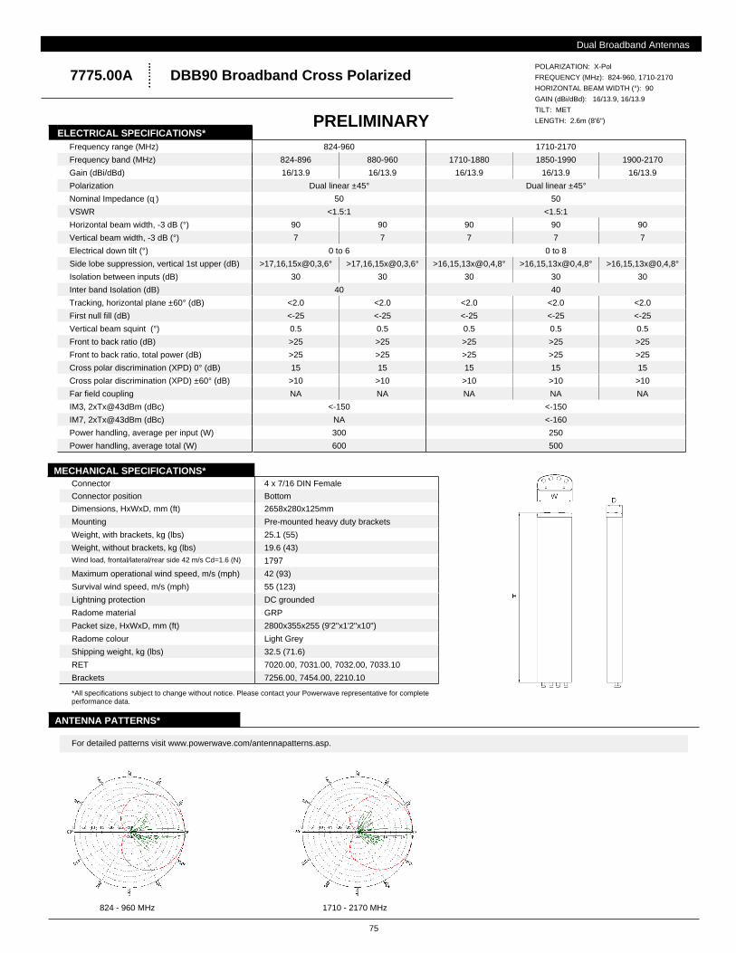
75
DBB90 Broadband Cross Polarized7775.00A
Connector
Connector position
Dimensions, HxWxD, mm (ft)
Weight, without brackets, kg (lbs)
Weight, with brackets, kg (lbs)
Wind load, frontal/lateral/rear side 42 m/s Cd=1.6 (N)
Maximum operational wind speed, m/s (mph)
Survival wind speed, m/s (mph)
4 x 7/16 DIN Female
Bottom
2658x280x125mm
19.6 (43)
25.1 (55)
1797
42 (93)
55 (123)
Lightning protection
Radome material
Radome colour
Mounting
Packet size, HxWxD, mm (ft)
Shipping weight, kg (lbs)
Brackets
DC grounded
GRP
Light Grey
Pre-mounted heavy duty brackets
2800x355x255 (9'2"x1'2"x10")
32.5 (71.6)
7256.00, 7454.00, 2210.10
MECHANICAL SPECIFICATIONS*
ANTENNA PATTERNS*
*All specifications subject to change without notice. Please contact your Powerwave representative for complete performance data.
For detailed patterns visit www.powerwave.com/antennapatterns.asp.
Frequency range (MHz) 824-960 1710-2170
Front to back ratio (dB) >25 >25 >25 >25 >25
Front to back ratio, total power (dB) >25 >25 >25 >25 >25
Cross polar discrimination (XPD) 0° (dB) 15 15 15 15 15
Tracking, horizontal plane ±60° (dB) <2.0 <2.0 <2.0 <2.0 <2.0
First null fill (dB) <-25 <-25 <-25 <-25 <-25
Vertical beam squint (°) 0.5 0.5 0.5 0.5 0.5
IM7, 2xTx@43dBm (dBc) NA <-160
Power handling, average per input (W) 300 250
Power handling, average total (W) 600 500
Cross polar discrimination (XPD) ±60° (dB) >10 >10 >10 >10 >10
Far field coupling NA NA NA NA NA
IM3, 2xTx@43dBm (dBc) <-150 <-150
Nominal Impedance (ɋ) 50 50
VSWR <1.5:1 <1.5:1
Polarization Dual linear ±45° Dual linear ±45°
Frequency band (MHz) 824-896 880-960 1710-1880 1850-1990 1900-2170
Gain (dBi/dBd) 16/13.9 16/13.9 16/13.9 16/13.9 16/13.9
Horizontal beam width, -3 dB (°) 90 90 90 90 90
Isolation between inputs (dB) 30 30 30 30 30
Inter band Isolation (dB) 40 40
Side lobe suppression, vertical 1st upper (dB) >17,16,15x@0,3,6° >17,16,15x@0,3,6° >16,15,13x@0,4,8° >16,15,13x@0,4,8° >16,15,13x@0,4,8°
Vertical beam width, -3 dB (°) 7 7 7 7 7
Electrical down tilt (°) 0 to 6 0 to 8
ELECTRICAL SPECIFICATIONS*
RET 7020.00, 7031.00, 7032.00, 7033.10
GAIN (dBi/dBd): 16/13.9, 16/13.9
TILT: MET
LENGTH: 2.6m (8'6")
POLARIZATION: X-Pol
FREQUENCY (MHz): 824-960, 1710-2170
HORIZONTAL BEAM WIDTH (°): 90
824 - 960 MHz 1710 - 2170 MHz
PRELIMINARY
Dual Broadband Antennas
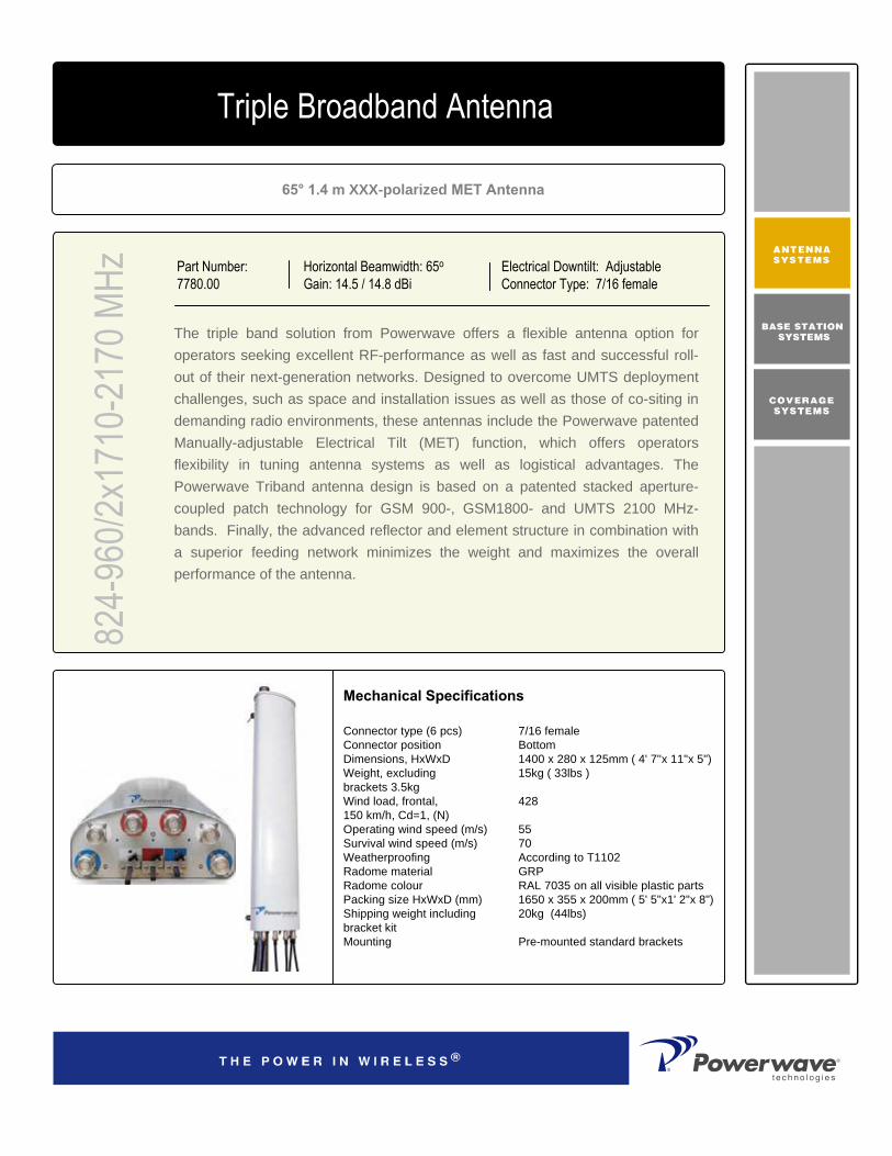
The triple band solution from Powerwave offers a flexible antenna option for operators seeking excellent RF-performance as well as fast and successful roll-out of their next-generation networks. Designed to overcome UMTS deployment challenges, such as space and installation issues as well as those of co-siting in demanding radio environments, these antennas include the Powerwave patented Manually-adjustable Electrical Tilt (MET) function, which offers operators flexibility in tuning antenna systems as well as logistical advantages. The Powerwave Triband antenna design is based on a patented stacked aperture-coupled patch technology for GSM 900-, GSM1800- and UMTS 2100 MHz-bands. Finally, the advanced reflector and element structure in combination with a superior feeding network minimizes the weight and maximizes the overall performance of the antenna.
65° 1.4 m XXX-polarized MET Antenna
Part Number:7780.00
Horizontal Beamwidth: 65o
Gain: 14.5 / 14.8 dBiElectrical Downtilt: AdjustableConnector Type: 7/16 female
Connector type (6 pcs) Connector position Dimensions, HxWxD Weight, excluding brackets 3.5kg Wind load, frontal, 150 km/h, Cd=1, (N) Operating wind speed (m/s) Survival wind speed (m/s) Weatherproofing Radome material Radome colour Packing size HxWxD (mm) Shipping weight including bracket kit Mounting
Mechanical Specifications
7/16 female Bottom 1400 x 280 x 125mm ( 4' 7''x 11"x 5") 15kg ( 33lbs )
428
55 70 According to T1102 GRP RAL 7035 on all visible plastic parts 1650 x 355 x 200mm ( 5' 5"x1' 2"x 8") 20kg (44lbs)
Pre-mounted standard brackets
824-
960/2
x171
0-21
70 M
HzTriple Broadband Antenna

D03
1-08
210
Rev
A
Corporate HeadquartersPowerwave Technologies, Inc. 1801 East St. Andrew PlaceSanta Ana, CA 92705 USA
Tel: 714-466-1000Fax: 714-466-5800 www.powerwave.com
Main European OfficeAntennvägen 6SE-187 80 TäbySwedenTel: +46 8 540 822 00Fax: +46 8 540 823 40
©Copyright March 2005, Powerwave Technologies, Inc. All Rights reserved. Powerwave, Powerwave Technologies, The Power in Wireless and the Powerwave logo are registered trademarks of Powerwave Technologies, Inc.
Main Asia Pacific Office23 F Tai Yau Building181 Johnston RoadWanchai, Hong KongTel: +852 2512 6123Fax: +852 2575 4860
900MHz 1800MHz 2100MHz
Frequency band, MHz Gain ± 0.5(dBi) Polarization Nominal impedance (W) VSWR, 824-960 MHz VSWR, 1710-1880 MHz VSWR, 1900-2025MHz VSWR, 2110-2170MHz Isolation between inputs (dB), 824-960 MHz Isolation between inputs (dB), 1710-1880 MHz Isolation between inputs (dB), 1900-2025 MHz Isolation between inputs (dB), 2110-2170 MHz Inter band isolation, all bands (dB) Horizontal -3dB beam width Tracking, Horizontal plane, 824-896 MHz, ±60°Tracking, Horizontal plane, 880-960 MHz, ±60°Tracking, Horizontal plane, 1710-1880 MHz, ±60°Tracking, Horizontal plane, 1900-2025 MHz, ±60°Tracking, Horizontal plane, 2110-2170 MHz, ±60°Electrical down tilt range (adjustable) Vertical Beam width -3dB MHz Side lobe suppression, Vertical 1stupper (dB)
Side lobe suppression, Vertical Upper (dB) Vertical beam squint Front-to-back Ratio (dB) Front-to-back Ratio, Total Power (dB) Cross-polar discrimination (XPD) ±60° (dB) IM3, 2Tx@43dBm (dBm) (dBc)IM3, 2Tx@43dBm (dBm) (dBc) IM7, 2Tx@43dBm (dBm) (dBc) Power Handling, Average per input (W) Power Handling, Average total (W)
824-960 14.5 dual linear ±45°50 1.5:1
30
68° ± 5°<2.0dB <2.0dB
2° to12°14°±2°>17, 16, 15, 14 X= 2, 4, 8, 12° MET >10 1°>28>25 >11 -153
300 600
1710-1880 14.4 dual linear ±45°50
1.5:1
30
38 65° ± 5°
<1.5dB
0° to12°14°±1°>17, 16, 15, 14 X=0, 4, 8, 12° MET >10 1°>30 >25 >11
-153
250 500
1900-2170 14.8 dual linear ±45°50
1.5:1 1.5:1
>30 >30
62° ± 5°
<1.5dB <1.5dB 0° to12°13°±1°>17, 16, 15, 14 X=0, 4, 8, 12° MET >10 1°>30 >25 >10
-160 250 500
Electrical Specifications
824-
960/2
x171
0-21
70 M
HzTriple Broadband Antenna
All specifications are subject to change without notice. Contact your Powerwave representative for complete performance data.

The triple band solution from Powerwave offers a flexible antenna option for operators seeking excellent RF-performance as well as fast and successful roll-out of their next-generation networks. Designed to overcome UMTS deployment challenges, such as space and installation issues as well as those of co-siting in demanding radio environments, these antennas include the Powerwave patented Manually-adjustable Electrical Tilt (MET) function, which offers operators flexibility in tuning antenna systems as well as logistical advantages. The Powerwave Triband antenna design is based on a patented stacked aperture-coupled patch technology for cellular 800, GSM 900-, GSM1800, PCS 1900 and UMTS 2100 MHz-bands. Finally, the advanced reflector and element structure incombination with a superior feeding network minimizes the weight and maximizes the overall performance of the antenna.
65° 2.0 m XXX-polarized MET Antenna
Part Number:7782.00
Horizontal Beamwidth: 65°
Gain: 16.5 / 16.8 dBiElectrical Downtilt: AdjustableConnector Type: 7/16 DIN female
Connector Type (6 Pcs) Connector Position Dimensions, HxWxD Weight, Excluding Brackets 3.5kg Wind Load, Frontal, 150 km/h, Cd=1, (N) Operating Wind Speed (M/s) Survival Wind Speed (M/s) Lightning Protection Weatherproofing Radome Material Radome Color Packing Size Hxwxd (Mm) Shipping Weight Including Bracket Kit Mounting
Mechanical Specifications
7/16 DIN female Bottom 2033 x 280 x 125mm ( 7' 1''x 11"x 5") 18kg ( 40lbs ) 21.5kg (47 lbs with brackets)
62855 (123 mph)70 (156 mph)DC-grounded According to T1102 GRP RAL 7035 on all visible plastic parts 2175x355x25523.5kg (51 lbs)Pre-mounted standard brackets
Triple Band Antenna82
4-96
0/2x1
710-
2170
MHz
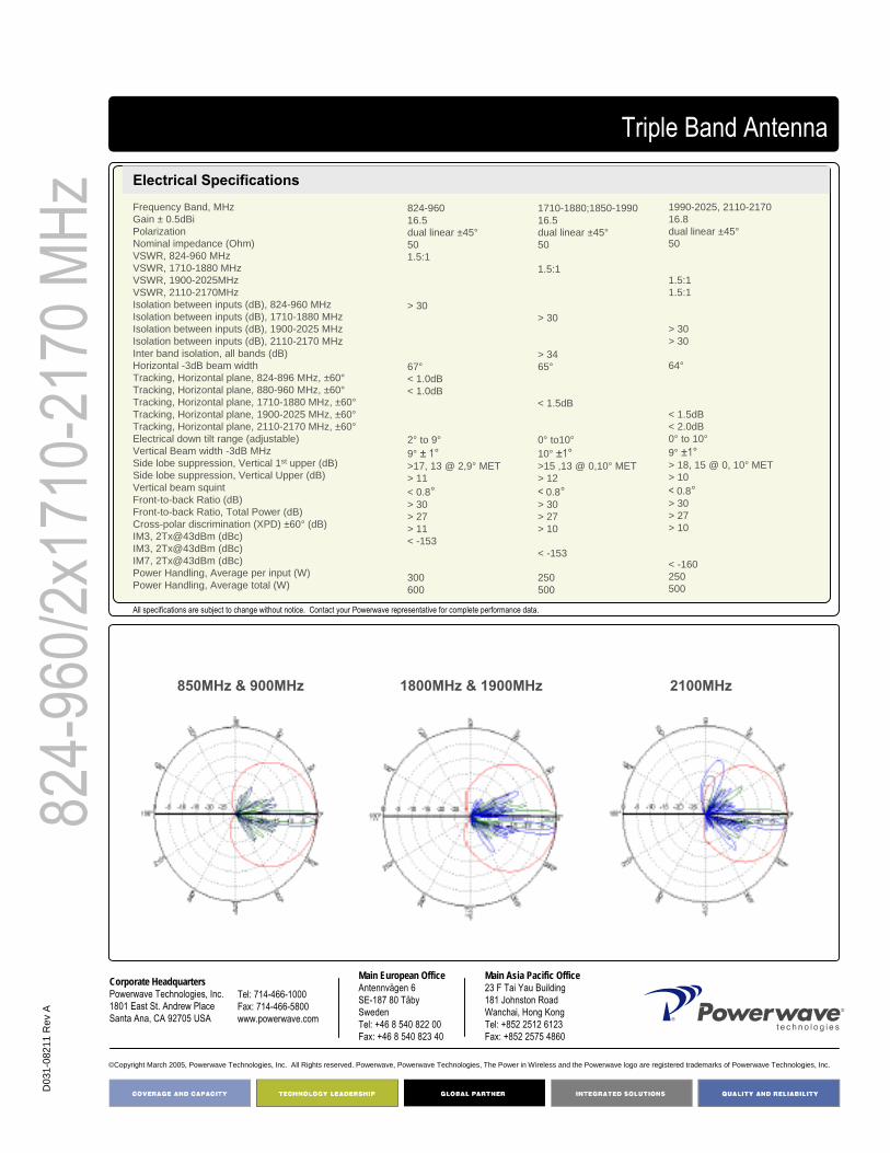
COVERAGE ANDCAPACITY
TECHNOLOGY LEADERSHIP
NETWORK OPTIMIZATION
QUALITY AND RELIABILITY
D03
1-08
211
Rev
A
Corporate HeadquartersPowerwave Technologies, Inc. 1801 East St. Andrew PlaceSanta Ana, CA 92705 USA
Tel: 714-466-1000Fax: 714-466-5800 www.powerwave.com
Main European OfficeAntennvägen 6SE-187 80 TäbySwedenTel: +46 8 540 822 00Fax: +46 8 540 823 40
©Copyright March 2005, Powerwave Technologies, Inc. All Rights reserved. Powerwave, Powerwave Technologies, The Power in Wireless and the Powerwave logo are registered trademarks of Powerwave Technologies, Inc.
Main Asia Pacific Office23 F Tai Yau Building181 Johnston RoadWanchai, Hong KongTel: +852 2512 6123Fax: +852 2575 4860
850MHz & 900MHz 1800MHz & 1900MHz 2100MHz
Frequency Band, MHz Gain ± 0.5dBi Polarization Nominal impedance (Ohm) VSWR, 824-960 MHz VSWR, 1710-1880 MHz VSWR, 1900-2025MHz VSWR, 2110-2170MHz Isolation between inputs (dB), 824-960 MHz Isolation between inputs (dB), 1710-1880 MHz Isolation between inputs (dB), 1900-2025 MHz Isolation between inputs (dB), 2110-2170 MHz Inter band isolation, all bands (dB) Horizontal -3dB beam width Tracking, Horizontal plane, 824-896 MHz, ±60°Tracking, Horizontal plane, 880-960 MHz, ±60°Tracking, Horizontal plane, 1710-1880 MHz, ±60°Tracking, Horizontal plane, 1900-2025 MHz, ±60°Tracking, Horizontal plane, 2110-2170 MHz, ±60°Electrical down tilt range (adjustable) Vertical Beam width -3dB MHz Side lobe suppression, Vertical 1st upper (dB) Side lobe suppression, Vertical Upper (dB) Vertical beam squint Front-to-back Ratio (dB) Front-to-back Ratio, Total Power (dB) Cross-polar discrimination (XPD) ±60° (dB) IM3, 2Tx@43dBm (dBc)IM3, 2Tx@43dBm (dBc)IM7, 2Tx@43dBm (dBc)Power Handling, Average per input (W) Power Handling, Average total (W)
824-960 16.5dual linear ±45°50 1.5:1
> 30
67°< 1.0dB < 1.0dB
2° to 9°9° ± 1°>17, 13 @ 2,9° MET > 11 < 0.8°> 30 > 27 > 11 < -153
300 600
1710-1880;1850-1990 16.5dual linear ±45°50
1.5:1
> 30
> 34 65°
< 1.5dB
0° to10°10° ±1°>15 ,13 @ 0,10° MET > 12 < 0.8°> 30> 27> 10
< -153
250 500
1990-2025, 2110-2170 16.8dual linear ±45°50
1.5:1 1.5:1
> 30 > 30
64°
< 1.5dB < 2.0dB 0° to 10°9° ±1°> 18, 15 @ 0, 10° MET > 10 < 0.8°> 30> 27> 10
< -160 250 500
Electrical Specifications
Triple Band Antenna
824-
960/2
x171
0-21
70 M
Hz
All specifications are subject to change without notice. Contact your Powerwave representative for complete performance data.

The triple band solution from Powerwave offers a flexible antenna option for operators seeking excellent RF-performance as well as fast and successful roll-out of their next-generation networks. Designed to overcome UMTS deployment challenges, such as space and installation issues as well as those of co-siting in demanding radio environments, these antennas include the Powerwave patented Manually-adjustable Electrical Tilt (MET) function, which offers operators flexibility in tuning antenna systems as well as logistical advantages. The Powerwave Triband antenna design is based on a patented stacked aperture-coupled patch technology for cellular 800, GSM 900-, GSM1800, PCS 1900 and UMTS 2100 MHz-bands. Finally, the advanced reflector and element structure incombination with a superior feeding network minimizes the weight and maximizes the overall performance of the antenna.
65° 2.6 m XXX-polarized MET Antenna
Triple Broadband Antenna
Part Number:7785.00
824-
960/2
x171
0-21
70 M
Hz Horizontal Beamwidth: 65°Gain: 17.4 / 17.5 dBi
Electrical Downtilt: AdjustableConnector Type: 7/16 DIN female
Connector Type (6 Pcs) Connector Position Dimensions, HxWxD Weight, Excluding Brackets 3.5kg Wind Load, Frontal, 150 km/h, Cd=1, (N) Operating Wind Speed Survival Wind Speed Lightning Protection Weatherproofing Radome Material Radome Color Packing Size Hxwxd (Mm) Shipping Weight Including Bracket Kit Mounting
Mechanical Specifications
7/16 DIN female Bottom 2650 x 280 x 125mm ( 8' 8''x 11"x 5") 24kg ( 53lbs ) 27,5kg (60.5 lbs with brackets)820
55m/s (123 mph)70m/s (156 mph)DC-grounded According to T1102 GRP RAL 7035 on all visible plastic parts 2790 x 355 x 200mm ( 9' 2"x1' 2"x 8")
29kg (64lbs)Pre-mounted standard brackets

COVERAGE ANDCAPACITY
TECHNOLOGY LEADERSHIP
NETWORK OPTIMIZATION
QUALITY AND RELIABILITY
D03
1-08
212
Rev
A
Corporate HeadquartersPowerwave Technologies, Inc. 1801 East St. Andrew PlaceSanta Ana, CA 92705 USA
Tel: 714-466-1000Fax: 714-466-5800 www.powerwave.com
Main European OfficeAntennvägen 6SE-187 80 TäbySwedenTel: +46 8 540 822 00Fax: +46 8 540 823 40
©Copyright March 2005, Powerwave Technologies, Inc. All Rights reserved. Powerwave, Powerwave Technologies, The Power in Wireless and the Powerwave logo are registered trademarks of Powerwave Technologies, Inc.
Main Asia Pacific Office23 F Tai Yau Building181 Johnston RoadWanchai, Hong KongTel: +852 2512 6123Fax: +852 2575 4860
824-
960/2
x171
0-21
70 M
Hz
850MHz & 900MHz 1800MHz & 1900MHz 2100MHz
Frequency Band, MHz Gain ± 0.5dBi Polarization Nominal impedance (Ohms) VSWR, 824-960 MHz VSWR, 1710-1880 MHz VSWR, 1900-2025MHz VSWR, 2110-2170MHz Isolation between inputs (dB), 824-960 MHz Isolation between inputs (dB), 1710-1880 MHz Isolation between inputs (dB), 1900-2025 MHz Isolation between inputs (dB), 2110-2170 MHz Inter band isolation, all bands (dB) Horizontal -3dB beam width Tracking, Horizontal plane, 824-896 MHz, ±60°Tracking, Horizontal plane, 880-960 MHz, ±60°Tracking, Horizontal plane, 1710-1880 MHz, ±60°Tracking, Horizontal plane, 1900-2025 MHz, ±60°Tracking, Horizontal plane, 2110-2170 MHz, ±60°Electrical down tilt range (adjustable) Vertical Beam width -3dB MHz Side lobe suppression, Vertical 1st upper (dB) Side lobe suppression, Vertical Upper (dB) Vertical beam squint Front-to-back Ratio (dB) Front-to-back Ratio, Total Power (dB) Cross-polar discrimination (XPD) ±60° (dB) IM3, 2Tx@43dBm (dBm) (dBc)IM3, 2Tx@43dBm (dBm) (dBc)IM7, 2Tx@43dBm (dBm) (dBc)Power Handling, Average per input (W) Power Handling, Average total (W)
824-960 17.4 dual linear ±45°50 1.5:1
30
65°<2.0dB <2.0dB
2° to 8°7°>17 @ 2 ° MET >10 0.5>25 >20 >11 -153
300 600
1710-1880;1850-1990 17.2 dual linear ±45°50
1.5:1
30
38 65°
<1.5dB
0° to 8°7°>17 @ 0° MET >10 0.5>30 >25 >11
-153
250 500
1990-2170 17.5 dual linear ±45°50
1.5:1 1.5:1
>30 >30
62°
<1.5dB <1.5dB 0° to 8°6°>17 @ 0 ° MET >10 0.5 >30 >25 >10
-160 250 500
Triple Broadband Antenna
Electrical Specifications
All specifications are subject to change without notice. Contact your Powerwave representative for complete performance data.
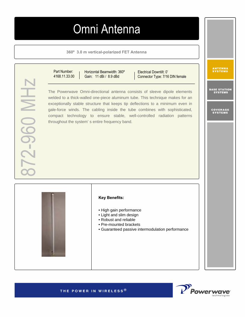
Part Number:4168.11.33.00
Horizontal Beamwidth: 360ºGain: 11 dBi / 8.9 dBd
Electrical Downtilt: 0o
Connector Type: 7/16 DIN female
872-
960 M
Hz4168.11.33.00 Omni Antenna
360º 3.0 m vertical-polarized FET Antenna
The Powerwave Omni-directional antenna consists of sleeve dipole elements welded to a thick-walled one-piece aluminum tube. This technique makes for an exceptionally stable structure that keeps tip deflections to a minimum even in gale-force winds. The cabling inside the tube combines with sophisticated, compact technology to ensure stable, well-controlled radiation patterns throughout the system’ s entire frequency band.
Key Benefits:
• High gain performance• Light and slim design • Robust and reliable• Pre-mounted brackets• Guaranteed passive intermodulation performance

PN77
22.0
0 R
EV.2
©Copyright September 2003, Powerwave Technologies, Inc. All Rights reserved. Powerwave, Powerwave Technologies, The Power in Wireless and the Powerwave logo are registered trademarks of Powerwave Technologies, Inc.
Corporate HeadquartersPowerwave Technologies, Inc. 1801 East St. Andrew PlaceSanta Ana, CA 92705 USA
Tel: 714-466-1000Fax: 714-466-5800 www.powerwave.com
Main European OfficeAntennvägen 6SE-187 80 TäbySwedenTel: +46 8 540 822 00Fax: +46 8 540 823 40
Main Asia Pacific Office23 F Tai Yau Building181 Johnston RoadWanchai, Hong KongTel: +852 2512 6123Fax: +852 2575 4860
872-
960 M
Hz
7/16 DIN femaleConnector Type
BottomConnector Position
3000x78mm (9‘10"x3")Dimensions, HxWxD
300NWind Load, Frontal, 42 m/s Cd=1 (N)
70 m/s (156 mph)Survival Wind Speed
< 1°Wind Deflection 35 m/s
DC groundedLightning Protection
PVCRadome Material
Light GrayRadome Color
3300x150x170mm (10'10"x6"x7")
Packing Size
16kg (35lbs)Shipping Weight
Mechanical Specifications
Electrical Specifications
Frequency band (MHz) 872-960 Gain, ± 0.5 (dBi) 11 (dBd) 8.9 Polarization Linear vertical Nominal Impedance (Ohms) 50 VSWR <1.4:1 Horizontal -3 dB beamwidth 360° Electrical downtilt 0° Vertical - 3dB Beamwidth 6.5 Vertical beam squint 0.5° IM3, 2Tx@43dBm (dBc) <-146
Omni Antenna
Typical Horizontal and Vertical
4168.11.33.00 Patterns
All specifications are subject to change without notice.Contact your Powerwave representative for complete performance data.

Part Number:4168.11.33.02
Horizontal Beamwidth: 360ºGain: 11 dBi / 8.9 dBd
Electrical Downtilt: 2o
Connector Type: 7/16 DIN female
872-
960 M
Hz4168.11.33.00 Omni Antenna
360º 3.0 m vertical-polarized FET Antenna
The Powerwave Omni-directional antenna consists of sleeve dipole elements welded to a thick-walled one-piece aluminum tube. This technique makes for an exceptionally stable structure that keeps tip deflections to a minimum even in gale-force winds. The cabling inside the tube combines with sophisticated, compact technology to ensure stable, well-controlled radiation patterns throughout the system’ s entire frequency band.
Key Benefits:
• High gain performance• Light and slim design• Robust and reliable• Pre-mounted brackets• Guaranteed passive intermodulation performance

PN77
22.0
0 R
EV 2
©Copyright September 2003, Powerwave Technologies, Inc. All Rights reserved. Powerwave, Powerwave Technologies, The Power in Wireless and the Powerwave logo are registered trademarks of Powerwave Technologies, Inc.
Corporate HeadquartersPowerwave Technologies, Inc. 1801 East St. Andrew PlaceSanta Ana, CA 92705 USA
Tel: 714-466-1000Fax: 714-466-5800 www.powerwave.com
Main European OfficeAntennvägen 6SE-187 80 TäbySwedenTel: +46 8 540 822 00Fax: +46 8 540 823 40
Main Asia Pacific Office23 F Tai Yau Building181 Johnston RoadWanchai, Hong KongTel: +852 2512 6123Fax: +852 2575 4860
872-
960 M
Hz
7/16 DIN femaleConnector Type
BottomConnector Position
3000x78mm (9‘10"x3")Dimensions, HxWxD
300NWind Load, Frontal, 42 m/s Cd=1 (N)
70 m/s (156 mph)Survival Wind Speed
< 1°Wind Deflection 35 m/s
DC groundedLightning Protection
PVCRadome Material
Light GrayRadome Color
3300x150x170mm (10'10"x6"x7")
Packing Size
16kg (35lbs)Shipping Weight
Mechanical Specifications
Electrical Specifications
Frequency band (MHz) 872-960 Gain, ± 0.5 (dBi) 11 (dBd) 8.9 Polarization Linear vertical Nominal Impedance (Ohms) 50 VSWR <1.4:1 Horizontal -3 dB beamwidth 360° Electrical downtilt 2° Vertical - 3dB Beamwidth 6.5 Vertical beam squint 0.5° IM3, 2Tx@43dBm (dBc) <-146
Omni Antenna
Typical Horizontal and Vertical
4168.11.33.02 Patterns
All specifications are subject to change without notice.Contact your Powerwave representative for complete performance data.

Part Number:4168.11.33.03
Horizontal Beamwidth: 360ºGain: 11 dBi / 8.9 dBd
Electrical Downtilt: 3o
Connector Type: 7/16 DIN female
872-
960 M
Hz4168.11.33.00 Omni Antenna
360º 3.0 m vertical-polarized FET Antenna
The Powerwave Omni-directional antenna consists of sleeve dipole elements welded to a thick-walled one-piece aluminum tube. This technique makes for an exceptionally stable structure that keeps tip deflections to a minimum even in gale-force winds. The cabling inside the tube combines with sophisticated, compact technology to ensure stable, well-controlled radiation patterns throughout the system’ s entire frequency band.
Key Benefits:
• High gain performance• Light and slim design• Robust and reliable• Pre-mounted brackets• Guaranteed passive intermodulation performance

PN77
22.0
0 R
EV. 2
©Copyright September 2003, Powerwave Technologies, Inc. All Rights reserved. Powerwave, Powerwave Technologies, The Power in Wireless and the Powerwave logo are registered trademarks of Powerwave Technologies, Inc.
Corporate HeadquartersPowerwave Technologies, Inc. 1801 East St. Andrew PlaceSanta Ana, CA 92705 USA
Tel: 714-466-1000Fax: 714-466-5800 www.powerwave.com
Main European OfficeAntennvägen 6SE-187 80 TäbySwedenTel: +46 8 540 822 00Fax: +46 8 540 823 40
Main Asia Pacific Office23 F Tai Yau Building181 Johnston RoadWanchai, Hong KongTel: +852 2512 6123Fax: +852 2575 4860
872-
960 M
Hz
7/16 DIN femaleConnector Type
BottomConnector Position
3000x78mm (9‘10"x3")Dimensions, HxWxD
300NWind Load, Frontal, 42 m/s Cd=1 (N)
70 m/s (156 mph)Survival Wind Speed
< 1°Wind Deflection 35 m/s
DC groundedLightning Protection
PVCRadome Material
Light GrayRadome Color
3300x150x170mm (10'10"x6"x7")
Packing Size
16kg (35lbs)Shipping Weight
Mechanical Specifications
Electrical Specifications
Frequency band (MHz) 872-960 Gain, ± 0.5 (dBi) 11 (dBd) 8.9 Polarization Linear vertical Nominal Impedance (Ohms) 50 VSWR <1.4:1 Horizontal -3 dB beamwidth 360° Electrical downtilt 3° Vertical - 3dB Beamwidth 6.5 Vertical beam squint 0.5° IM3, 2Tx@43dBm (dBc) <-146
Omni Antenna
Typical Horizontal and Vertical
4168.11.33.03 Patterns
All specifications are subject to change without notice.Contact your Powerwave representative for complete performance data.

360° 3.0 m vertical-polarized FET Antenna
Part Number4168.11.33.06
Horizontal Beamwidth: 360°Gain: 11 dBi
Electrical Downtilt: 6°Connector Type: DIN
Powerwave Technologies’ Omni directional antenna consists of sleeve dipole elements welded to a thick-walled one-piece aluminum tube. This technique makes for an exceptionally stable structure that keeps tip deflections to a minimum even in gale-force winds. The cabling inside the tube combines with sophisticated, compact technology to ensure stable, well-controlled radiation patterns throughout the system’ s entire frequency band.
900 M
Hz
900 MHz Omni Antenna
900 MHz Omni Antenna
Typical Horizontal and Vertical 4168.11.33.06 Patterns

COVERAGE ANDCAPACITY
TECHNOLOGY LEADERSHIP
NETWORK OPTIMIZATION
QUALITY AND RELIABILITY
PN 4
168.
11.3
3.06
RE
V.1
Corporate HeadquartersPowerwave Technologies, Inc. 1801 East St. Andrew PlaceSanta Ana, CA 92705 USA
Tel: 714-466-1000Fax: 714-466-5800 www.powerwave.com
Main European OfficeAntennvägen 6SE-187 80 TäbySwedenTel: +46 8 540 822 00Fax: +46 8 540 823 40
©Copyright February 2003, Powerwave Technologies, Inc. All Rights reserved. Powerwave, Powerwave Technologies, The Power in Wireless and the Powerwave logo are registered trademarks of Powerwave Technologies, Inc.
Main Asia Pacific Office23 F Tai Yau Building181 Johnston RoadWanchai, Hong KongTel: +852 2512 6123Fax: +852 2575 4860
900 MHz Omni Antenna
< -146IM, 3rd order, 2Tx@43 dBm (dBc)
500Maximum input power (W)
0.5°Vertical beam squint
6°Electrical downtilt
6.5°Vertical -3 dB beamwidth
360°Horizontal -3 dB beamwidth
<1.4:1VSWR
50Nominal Impedance (Ohm)
11Gain, ± 0.5 (dBi)
Linear verticalPolarization
872-960Frequency Range (MHz)
Electrical Specifications
Comments:
< 1°WindDdeflection 35 m/s
16kg (35lbs)Shipping Weight
3300x150x170mm (10'10"x6"x7")Packing Size
Light GrayRadome Color
PVCRadome Material
DC groundedLightningPprotection
70 m/s (156 mph)Survival Wind Speed
300Wind Load, Frontal, 42 m/s Cd=1 (N)
3000x78mm (9‘10"x3")Dimensions, HxWxD
BottomConnector Position
7/16 DIN femaleConnector Type
Mechanical Specifications
900 M
Hz
Gain is typical within frequency band.Radiation patterns are typical for the antenna. Shipping weight including tilt brackets. Antenna is delivered with brackets pre-mounted*Radome color is NCS 2502-B (RAL 7035).
All specifications are subject to change without notice.Contact factory for complete performance data.

Part Number:4168.11.33.52
Horizontal Beamwidth: 360ºGain: 11 dBi / 8.9 dBd
Electrical Downtilt: 2° upside downConnector Type: 7/16 DIN female
872-
960 M
Hz4168.11.33.00 Omni Antenna
360º 3.0 m vertical-polarized FET Antenna
The Powerwave Omni-directional antenna consists of sleeve dipole elements welded to a thick-walled one-piece aluminum tube. This technique makes for an exceptionally stable structure that keeps tip deflections to a minimum even in gale-force winds. The cabling inside the tube combines with sophisticated, compact technology to ensure stable, well-controlled radiation patterns throughout the system’ s entire frequency band.
Key Benefits:
• High gain performance• Light and slim design• Robust and reliable• Pre-mounted brackets• Guaranteed passive intermodulation performance

D03
1-08
111
Rev
A
©Copyright September 2003, Powerwave Technologies, Inc. All Rights reserved. Powerwave, Powerwave Technologies, The Power in Wireless and the Powerwave logo are registered trademarks of Powerwave Technologies, Inc.
Corporate HeadquartersPowerwave Technologies, Inc. 1801 East St. Andrew PlaceSanta Ana, CA 92705 USA
Tel: 714-466-1000Fax: 714-466-5800 www.powerwave.com
Main European OfficeAntennvägen 6SE-187 80 TäbySwedenTel: +46 8 540 822 00Fax: +46 8 540 823 40
Main Asia Pacific Office23 F Tai Yau Building181 Johnston RoadWanchai, Hong KongTel: +852 2512 6123Fax: +852 2575 4860
872-
960 M
Hz
7/16 DIN femaleConnector Type
BottomConnector Position
3000x78mm (9‘10"x3")Dimensions, HxWxD
300NWind Load, Frontal, 42 m/s Cd=1 (N)
70 m/s (156 mph)Survival Wind Speed
< 1°Wind Deflection 35 m/s
DC groundedLightning Protection
PVCRadome Material
Light GrayRadome Color
3300x150x170mm (10'10"x6"x7")
Packing Size
16kg (35lbs)Shipping Weight
Mechanical Specifications
Electrical Specifications
Frequency band (MHz) 872-960 Gain, ± 0.5 (dBi) 11 (dBd) 8.9 Polarization Linear vertical Nominal Impedance (Ohms) 50 VSWR <1.4:1 Horizontal -3 dB beamwidth 360° Electrical downtilt 2° upside down Vertical - 3dB Beamwidth 6.5 Vertical beam squint 0.5° IM3, 2Tx@43dBm (dBc) <-146
Omni Antenna
Typical Horizontal and Vertical
4168.11.33.52 Patterns
All specifications are subject to change without notice.Contact your Powerwave representative for complete performance data.

Part Number:7336.00
Horizontal Beamwidth: 360°
Gain: 3 dBi/ 0.9 dBdElectrical Downtilt: 0°Connector Type: N female
800-
2500
MHz
4168.11.33.00
Key Benefits:
• Light and slim design• Robust and reliable• Guaranteed passive intermodulation performance
Multi-band Indoor Antenna
Omni Vertical polarized Antenna
Powerwave multi-band solutions provide substantial savings in overall cost because they require less equipment and maintenance and shorter installation times while offering lower site costs. Considering multi-band network potential, what you’re really doing is preparing for the future, today. Easy-to-install multi-band antennas from Powerwave are deployed in numerous wireless networks worldwide. All have endured extensive field trials in close collaboration with cell planners and other communications providers to ensure Powerwave multi-band antennas perform to expectations. Using fewer antennas of discreetly functional design beats using numerous antennas of provocative size and appearance especially with today’s aesthetic concerns.

D03
1-08
158
Rev
A
©Copyright September 2003, Powerwave Technologies, Inc. All Rights reserved. Powerwave, Powerwave Technologies, The Power in Wireless and the Powerwave logo are registered trademarks of Powerwave Technologies, Inc.
Corporate HeadquartersPowerwave Technologies, Inc. 1801 East St. Andrew PlaceSanta Ana, CA 92705 USA
Tel: 714-466-1000Fax: 714-466-5800 www.powerwave.com
Main European OfficeAntennvägen 6SE-187 80 TäbySwedenTel: +46 8 540 822 00Fax: +46 8 540 823 40
Main Asia Pacific Office23 F Tai Yau Building181 Johnston RoadWanchai, Hong KongTel: +852 2512 6123Fax: +852 2575 4860
800-
2500
MHz
185 mm (7”)Diameter/Width (mm)
0.36 kg (0.8lbs)Shipping weight
210 x 200 x 115mm (8"x8"x5")Packing Size
WhiteRadome Color
0.2 kg (0.44lbs)Weight
65 mm (2,5”)Depth
N femaleConnector Type
Mechanical Specifications
Electrical SpecificationsFrequency band (MHz) 800-2500
Gain, ± 0.5 (dBi/dBd) 3/0.9
Polarization Vertical
Nominal Impedance (Ohm) 50
VSWR <1.5:1
Beam width: Ceiling Mounted 360°
Beam width: Wall Mounted 70°Electrical downtilt 0°
IM3, 2Tx@43dBm (dBc) <-150
Power Handling, Average total (W) 40
Typical Horizontal 7336.00 Pattern
Multi-band Indoor Antenna
All specifications are subject to change without notice.Contact your Powerwave representative for complete performance data.

Part Number:7336.10
Horizontal Beamwidth: 90°/70°
Gain: 6/9 dBi/ 3.9/6.9 dBdElectrical Downtilt: 0°Connector Type: N female
800-
2500
MHz
4168.11.33.00
Key Benefits:
• Light and slim design• Robust and reliable• Guaranteed passive intermodulation performance
Multi-band Indoor AntennaVertical polarized Antenna
Powerwave multi-band solutions provide substantial savings in overall cost because they require less equipment and maintenance and shorter installation times while offering lower site costs. Considering multi-band network potential, what you’re really doing is preparing for the future, today. Easy-to-install multi-band antennas from Powerwave are deployed in numerous wireless networks worldwide. All have endured extensive field trials in close collaboration with cell planners and other communications providers to ensure Powerwave multi-band antennas perform to expectations. Using fewer antennas of discreetly functional design beats using numerous antennas of provocative size and appearance especially with today’s aesthetic concerns.

D03
1-08
159
Rev
A
©Copyright September 2003, Powerwave Technologies, Inc. All Rights reserved. Powerwave, Powerwave Technologies, The Power in Wireless and the Powerwave logo are registered trademarks of Powerwave Technologies, Inc.
Corporate HeadquartersPowerwave Technologies, Inc. 1801 East St. Andrew PlaceSanta Ana, CA 92705 USA
Tel: 714-466-1000Fax: 714-466-5800 www.powerwave.com
Main European OfficeAntennvägen 6SE-187 80 TäbySwedenTel: +46 8 540 822 00Fax: +46 8 540 823 40
Main Asia Pacific Office23 F Tai Yau Building181 Johnston RoadWanchai, Hong KongTel: +852 2512 6123Fax: +852 2575 4860
800-
2500
MHz
1.2 kg (2.6lbs)Shipping weight
240 x 280 x 45 mm (9"x11"x2")Packing Size
WhiteRadome Color
1.0 kg (2.2lbs)Weight
210 x 180 x 42 mm (8"x7"x2")Dimensions (LxWxD)
N femaleConnector Type
Mechanical Specifications
Electrical SpecificationsFrequency band (MHz)
Frequency range (MHz) 806-890 890-960 1710-2100 2100-2500
VSWR <1.9:1 <1.5:1 <1.9:1 <1.8:1
Gain, ± 0.5 (dBi/dBd) 6/3.9 6/3.9 9/6.9 9/6.9
Beam width: Ceiling Mounted - - - -
Beam width: Wall Mounted 90° 90° 70° 65°
Electrical downtilt
Polarization
Power Handling, Average total (W)
Nominal Impedance (Ohm)
IM3, 2Tx@43dBm (dBc)
50
<-150
800-2500
0°
Vertical
50
Typical Horizontal and Vertical 7336.10 Pattern
Multi-band Indoor Antenna
All specifications are subject to change without notice.Contact your Powerwave representative for complete performance data.

RET
Tech
nolog
y
The Single Band RET Unit is part of the Powerwave RET Technology and consists of a stepping motor that can be connected to the positioning rod used for adjusting the electrical down tilt of Powerwave MET antennas. Upon command from the MCU, the stepping motor moves the positioning rod up or down to achieve the desired antenna tilt angle.
The unit has dual RS-485 connectors for easy daisy chaining without the need for an external splitter. The unit can be mounted on site on an antenna that is already in place or can be delivered already mounted on a Powerwave antenna.
Single Band Remote Controlled Electrical Down-Tilt (RET)
Single Band RET Module
Easy configurationAISG Compatible Outdoor Usage
Key Benefits:
• Field upgradeable with installed MET antennas• Optional factory pre-mounting on MET antennas• Integrated RS-485 splitter for easy daisy chaining• Field proven vented design
Part Number:7010.00
Single Band Module

COVERAGE ANDCAPACITY
TECHNOLOGY LEADERSHIP
NETWORK OPTIMIZATION
QUALITY AND RELIABILITY
PN70
10.X
X
©Copyright 2005, Powerwave Technologies, Inc. All Rights reserved. Powerwave, Powerwave Technologies, The Power in Wireless and the Powerwave logo are registered trademarks of Powerwave Technologies, Inc.
Corporate HeadquartersPowerwave Technologies, Inc. 1801 East St. Andrew PlaceSanta Ana, CA 92705 USA
Tel: 714-466-1000Fax: 714-466-5800 www.powerwave.com
Main European OfficeAntennvägen 6SE-187 80 TäbySwedenTel: +46 8 540 822 00Fax: +46 8 540 823 40
Main Asia-Pacific Office23 F Tai Yau Building181 Johnston RoadWanchai, Hong KongTel: +852 2512 6123Fax: +852 2575 4860
RET
Tech
nolog
ySingle Band RET Module
The Powerwave RET system is designed to meet the high requirements for reliability, flexibility and efficiency in remote control of tower mounted telecommunication equipment.
The system consists of a Master Control Unit (MCU) that controls the Antenna Line Devices (ALDs) and supplies DC power to them via a common bus. ALDs are connected to the MCU using a separate ALD system cable or by using the existing RF feeders in your system.
Product Number
Power supplyCurrent consumption Start up surge Current draw during Antenna tilting
All other operational states
AISG Data Rate Rod positioning accuracyWeightDimensions (W,L,H) (mm)ConnectorsAISG output/ input Protection Ground
Operation temperature range
Type Approvals
MTBF Ingress protection Environmental
7010.00
+9 to+30V
< 1mC< 500 mA at Vin <10V< 400 mA at Vin <19V< 250 mA at Vin >19V
< 100 mA at Vin <19V< 50 mA at Vin >19V
9.6 kbps, 38.4kbps<± 0.8 mm1 kg < 62 X 78 X 216
IEC 60130-9 (Ed. 3.0)M6 screw
-40 to +65C
Conformity with the relevant provision(s) of thedirectives RTTE 99/5/EG and LVD 73/23/EEG.>500.000 hrs.IP65ETSI 300 019
Technical Specifications
All specifications subject to change without notice. Please contact your Powerwave representative for complete performance data.

Dual Band Remote Controlled Electrical Down-Tilt (RET)
Dual Band RET Module
Easy configurationAISG Compatible Outdoor Usage
Key Benefits:
• Field upgradeable with installed MET antennas• Optional factory pre-mounting on MET antennas• Integrated RS-485 splitter for easy daisy chaining• Field proven vented design• Fully integrated dual RET motor housing
Part Number:7020.00
The Dual Band RET Unit is part of the Powerwave RET Technology and consists of a stepping motor that can be connected to the positioning rod used for adjusting the electrical down tilt of Powerwave MET antennas. Upon command from the MCU, the stepping motor moves the positioning rod up or down to achieve the desired antenna tilt angle.
The unit has dual RS-485 connectors for easy daisy chaining without the need for an external splitter. The unit can be mounted on site on an antenna that is already in place or can be delivered already mounted on a Powerwave antenna.
RET
Tech
nolog
y
Dual Band Module
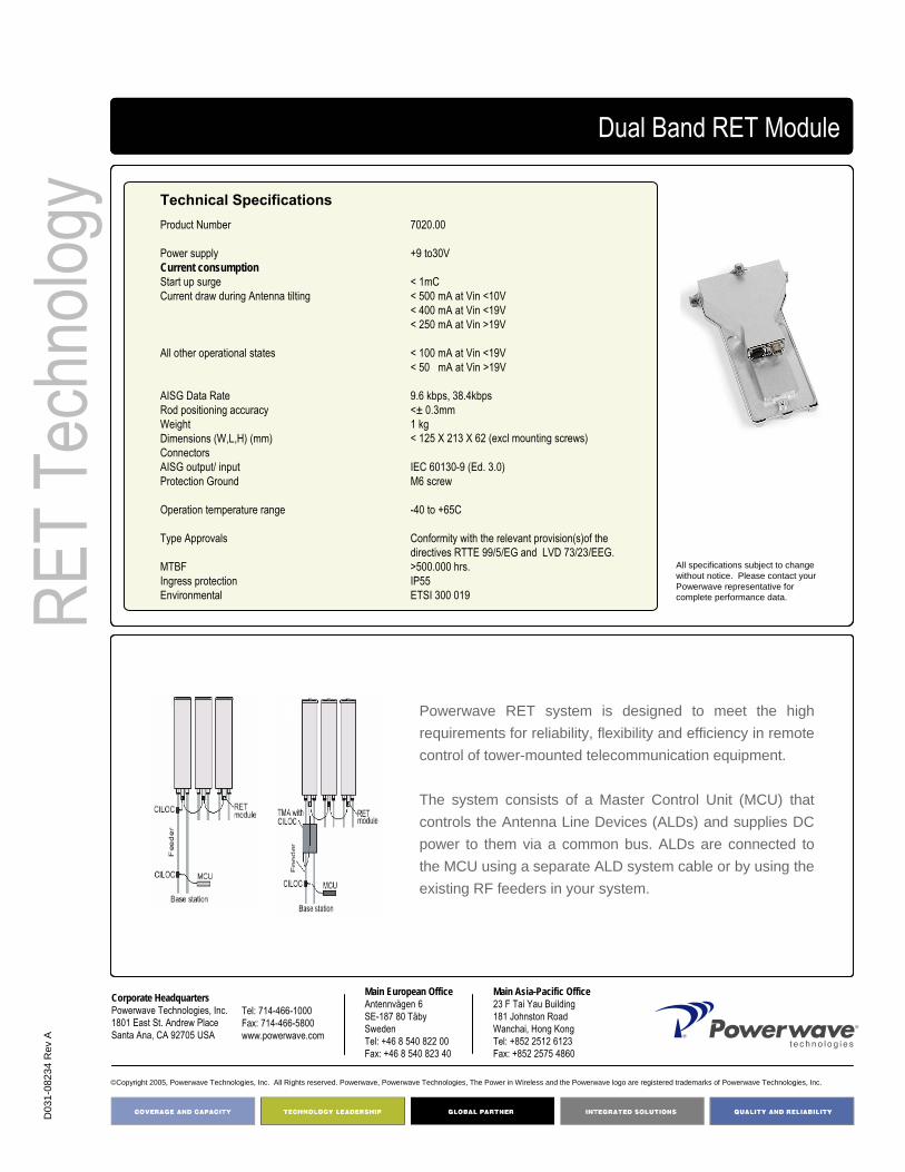
D03
1-08
234
Rev
A
Corporate HeadquartersPowerwave Technologies, Inc. 1801 East St. Andrew PlaceSanta Ana, CA 92705 USA
Tel: 714-466-1000Fax: 714-466-5800 www.powerwave.com
Main European OfficeAntennvägen 6SE-187 80 TäbySwedenTel: +46 8 540 822 00Fax: +46 8 540 823 40
©Copyright 2005, Powerwave Technologies, Inc. All Rights reserved. Powerwave, Powerwave Technologies, The Power in Wireless and the Powerwave logo are registered trademarks of Powerwave Technologies, Inc.
Main Asia-Pacific Office23 F Tai Yau Building181 Johnston RoadWanchai, Hong KongTel: +852 2512 6123Fax: +852 2575 4860
COVERAGE ANDCAPACITY
TECHNOLOGY LEADERSHIP
NETWORK OPTIMIZATION
QUALITY AND RELIABILITY
RET
Tech
nolog
yDual Band RET Module
Product Number
Power supplyCurrent consumptionStart up surge Current draw during Antenna tilting
All other operational states
AISG Data Rate Rod positioning accuracyWeightDimensions (W,L,H) (mm)ConnectorsAISG output/ input Protection Ground
Operation temperature range
Type Approvals
MTBF Ingress protection Environmental
7020.00
+9 to30V
< 1mC< 500 mA at Vin <10V< 400 mA at Vin <19V< 250 mA at Vin >19V
< 100 mA at Vin <19V< 50 mA at Vin >19V
9.6 kbps, 38.4kbps<± 0.3mm1 kg < 125 X 213 X 62 (excl mounting screws)
IEC 60130-9 (Ed. 3.0)M6 screw
-40 to +65C
Conformity with the relevant provision(s)of thedirectives RTTE 99/5/EG and LVD 73/23/EEG.>500.000 hrs.IP55ETSI 300 019
Powerwave RET system is designed to meet the high requirements for reliability, flexibility and efficiency in remote control of tower-mounted telecommunication equipment.
The system consists of a Master Control Unit (MCU) that controls the Antenna Line Devices (ALDs) and supplies DC power to them via a common bus. ALDs are connected to the MCU using a separate ALD system cable or by using the existing RF feeders in your system.
Technical Specifications
All specifications subject to change without notice. Please contact your Powerwave representative for complete performance data.

Triple Band Remote Controlled Electrical Down-Tilt (RET)
Triple Band RET Module
Easy configurationAISG Compatible Outdoor Usage
Part Number:7030.00
Key Benefits:
• Field upgradeable with installed MET antennas• Optional factory pre-mounting on MET antennas• Integrated RS-485 splitter for easy daisy chaining• Field proven vented design• Fully integrated triple RET motor housing
The Triple Band RET Unit is part of the Powerwave RET Technology and consists of a stepping motor that can be connected to the positioning rod used for adjusting the electrical down tilt of Powerwave MET antennas. Upon command from the MCU, the stepping motor moves the positioning rod up or down to achieve the desired antenna tilt angle.
The unit has dual RS-485 connectors for easy daisy chaining without the need for an external splitter. The unit can be mounted on site on an antenna that is already in place or can be delivered already mounted on a Powerwave antenna.
RET
Tech
nolog
y
Triple Band Module

COVERAGE ANDCAPACITY
TECHNOLOGY LEADERSHIP
NETWORK OPTIMIZATION
QUALITY AND RELIABILITY
PN00
0000
0-00
Corporate HeadquartersPowerwave Technologies, Inc. 1801 East St. Andrew PlaceSanta Ana, CA 92705 USA
Tel: 714-466-1000Fax: 714-466-5800 www.powerwave.com
Main European OfficeAntennvägen 6SE-187 80 TäbySwedenTel: +46 8 540 822 00Fax: +46 8 540 823 40
©Copyright 2005, Powerwave Technologies, Inc. All Rights reserved. Powerwave, Powerwave Technologies, The Power in Wireless and the Powerwave logo are registered trademarks of Powerwave Technologies, Inc.
Main Asia-Pacific Office23 F Tai Yau Building181 Johnston RoadWanchai, Hong KongTel: +852 2512 6123Fax: +852 2575 4860
Triple Band RET Module
Product Number
Power supplyCurrent consumption Start up surge Current draw during Antenna tilting
All other operational states
AISG Data Rate Rod positioning accuracyWeightDimensions (W,L,H) (mm)ConnectorsAISG output/ input Protection Ground
Operation temperature range
Type Approvals
MTBF Ingress protection Environmental
7030.00
+9 to30V
< 1mC< 500 mA at Vin <10V< 400 mA at Vin <19V< 250 mA at Vin >19V
< 100 mA at Vin <19V< 50 mA at Vin >19V
9.6 kbps, 38.4kbps<± 0.3mm1 kg < 125 X 213 X 62 (excl mounting screws)
IEC 60130-9 (Ed. 3.0)M6 screw
-40 to +65C
Conformity with the relevant provision(s)of thedirectives RTTE 99/5/EG and LVD 73/23/EEG.> 500.000 hrs.IP55ETSI 300 019
Technical Specifications
RET
Tech
nolog
y
All specifications subject to change without notice. Please contact your Powerwave representative for complete performance data.
Powerwave RET system is designed to meet the high requirements for reliability, flexibility and efficiency in remote control of tower-mounted telecommunication equipment.
The system consists of a Master Control Unit (MCU) that controls the Antenna Line Devices (ALDs) and supplies DC power to them via a common bus. ALDs are connected to the MCU using a separate ALD system cable or by using the existing RF feeders in your system.

215
Single Band E-RET7011.00
RET SYSTEM*
*All specifications subject to change without notice. Please contact your Powerwave representative for complete performance data.
Product Number 7011.00
Rod positioning accuracy <+/-0.3 mm
Data protocol ISO/IEC 8482 and 1056-ASC/RET interface
MTBF >1500.000 hrs.
Operation temperature range -40 to +65° C
Power consumption idle <1.5 W
Standard Ericsson
Power supply +12 to +30V
Power consumption during tilting <10 W
ELECTRICAL SPECIFICATIONS*
Weight 1 kg
Connectors output / input DIN 45 326
Ingress protection IP65
Environmental ETSI 300 019
Dimensions (W,L,H) (mm) <62 x 78 x 216
Connector Protection Ground M6 screw
MECHANICAL SPECIFICATIONS*
This system consists of a Master Control Unit (MCU) that controls the Antenna Line Devices (ALDs) and supplies DC power to them via a common bus, ALDs are connected to the MCU using a separate ALD system cable or by using the existing RF feeders in your system.
Powerwave RET system is designed to meet the high requirements for reliability, flexibility and efficiency in remote control of tower-mounted telecommunication equipment.
REMOTE ELECTRICAL TILT
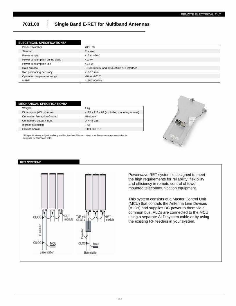
216
Single Band E-RET for Multiband Antennas7031.00
RET SYSTEM*
*All specifications subject to change without notice. Please contact your Powerwave representative for complete performance data.
Product Number 7031.00
Rod positioning accuracy <+/-0.3 mm
Data protocol ISO/IEC 8482 and 1056-ASC/RET interface
MTBF >1500.000 hrs.
Operation temperature range -40 to +65° C
Power consumption idle <1.5 W
Standard Ericsson
Power supply +12 to +30V
Power consumption during tilting <10 W
ELECTRICAL SPECIFICATIONS*
Weight 1 kg
Connectors output / input DIN 45 326
Ingress protection IP65
Environmental ETSI 300 019
Dimensions (W,L,H) (mm) <125 x 213 x 62 (excluding mounting screws)
Connector Protection Ground M6 screw
MECHANICAL SPECIFICATIONS*
This system consists of a Master Control Unit (MCU) that controls the Antenna Line Devices (ALDs) and supplies DC power to them via a common bus, ALDs are connected to the MCU using a separate ALD system cable or by using the existing RF feeders in your system.
Powerwave RET system is designed to meet the high requirements for reliability, flexibility and efficiency in remote control of tower-mounted telecommunication equipment.
REMOTE ELECTRICAL TILT
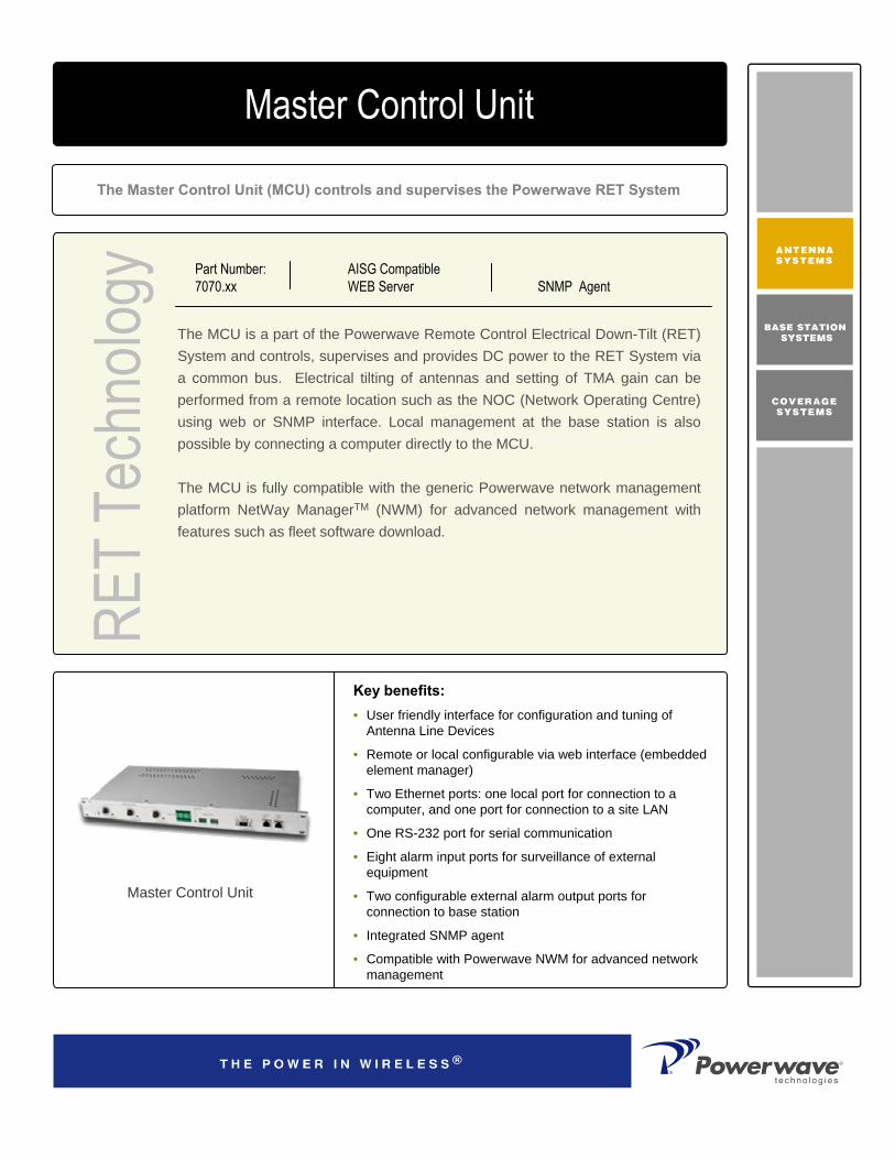
RET
Tech
nolog
y
The MCU is a part of the Powerwave Remote Control Electrical Down-Tilt (RET) System and controls, supervises and provides DC power to the RET System via a common bus. Electrical tilting of antennas and setting of TMA gain can be performed from a remote location such as the NOC (Network Operating Centre) using web or SNMP interface. Local management at the base station is also possible by connecting a computer directly to the MCU.
The MCU is fully compatible with the generic Powerwave network management platform NetWay ManagerTM (NWM) for advanced network management with features such as fleet software download.
The Master Control Unit (MCU) controls and supervises the Powerwave RET System
Master Control Unit
AISG Compatible WEB Server
Key benefits:• User friendly interface for configuration and tuning of
Antenna Line Devices
• Remote or local configurable via web interface (embedded element manager)
• Two Ethernet ports: one local port for connection to a computer, and one port for connection to a site LAN
• One RS-232 port for serial communication
• Eight alarm input ports for surveillance of external equipment
• Two configurable external alarm output ports for connection to base station
• Integrated SNMP agent
• Compatible with Powerwave NWM for advanced network management
SNMP AgentPart Number:7070.xx
Master Control Unit

COVERAGE ANDCAPACITY
TECHNOLOGY LEADERSHIP
NETWORK OPTIMIZATION
QUALITY AND RELIABILITY
PN70
70.X
X
©Copyright 2005, Powerwave Technologies, Inc. All Rights reserved. Powerwave, Powerwave Technologies, The Power in Wireless and the Powerwave logo are registered trademarks of Powerwave Technologies, Inc.
Corporate HeadquartersPowerwave Technologies, Inc. 1801 East St. Andrew PlaceSanta Ana, CA 92705 USA
Tel: 714-466-1000Fax: 714-466-5800 www.powerwave.com
Main European OfficeAntennvägen 6SE-187 80 TäbySwedenTel: +46 8 540 822 00Fax: +46 8 540 823 40
Main Asia-Pacific Office23 F Tai Yau Building181 Johnston RoadWanchai, Hong KongTel: +852 2512 6123Fax: +852 2575 4860
RET
Tech
nolog
yMaster Control Unit
Product Number Power supplyDC / Current consumption AC / Current consumption ALD supply voltage Max current draw per connector Total current draw all connectorsSurge at start up all connectorsLocal alarm ports (IN port)Output voltage at open Output current at closed Local control ports (Out ports, 3-pole relays)Max input Voltage Max input current AISG data rate WeightDimensions Connectors DC power supply AC power supply RET 1 to 3 Site LANLocal (Ethernet port)RS-232Local alarm Type Approvals
MTBF Operating temperature Environmental
7070.10 (AC) 7070.30 (24 V) 7070.50 (-48V)AC / 24V / -48V -48V /< 2.5A115/230 VAC 1.7 / 1.0A+24 V DC1.16 A3.48 A54 mC during <10 ms
5 ±1 V 5 ± 2mA
30 V DC0.5 A9.6 kbps, 38.4 kbps < 2,5 kg Width 19” rack, Height 44mm, Depth 207mm
CAP 2 Circuit universal MATE-N-LOK 350778-1IEC/EB60320-1 Male IEC 60130-9 (Ed. 3.0)4-pole RJ45 MDI4-pole RJ45 MDI9-pin d-SUB male Connector panel Conformity with the relevant provision(s)of thedirectives RTTE 99/5/EG and LVD 73/23/EEG.>250.000 hrs.-5C to 60CETSI 300 019 * Weather-protected locations*
Powerwave RET system is designed to meet the high requirements for reliability, flexibility and efficiency in remote control of tower mounted telecommunication equipment.
The system consists of a Master Control Unit (MCU) that controls the Antenna Line Devices (ALDs) and supplies DC power to them via a common bus. ALDs are connected to the MCU using a separate ALD system cable or by using the existing RF feeders in your system.
All specifications subject to change without notice. Please contact your Powerwave Representative for complete performance data.
Specifications

RET
Tech
nolog
y
The CILOC is part of the Powerwave RET System and makes it possible to connect antenna line devices (ALDs) to a Master Control Unit by using the RF feeder. The CILOC is used for transferring DC supply and data signals to the ALDs.
The external DC supply and RS-485 signals on the CILOC unit are applied through a multi-pole connector. The DC supply and RS-485 signal interface is implemented in accordance to the AISG specification.
CILOC for communication and DC supply over the RF feeder to the ALDs
Current Injector Layer One Converter
AISG Compatible Outdoor Usage
Key Benefits:
• Easy configuration and tuning of new equipment
• Power control and cell breathing by varying antenna coverage footprints
• Fine tuning of soft handover situation during live operation
Part Number:7060.00 ANT7060.10 BTS
Current Injector Layer 1 Converter

COVERAGE ANDCAPACITY
TECHNOLOGY LEADERSHIP
NETWORK OPTIMIZATION
QUALITY AND RELIABILITY
PN00
0000
0-00
©Copyright 2005, Powerwave Technologies, Inc. All Rights reserved. Powerwave, Powerwave Technologies, The Power in Wireless and the Powerwave logo are registered trademarks of Powerwave Technologies, Inc.
Corporate HeadquartersPowerwave Technologies, Inc. 1801 East St. Andrew PlaceSanta Ana, CA 92705 USA
Tel: 714-466-1000Fax: 714-466-5800 www.powerwave.com
Main European OfficeAntennvägen 6SE-187 80 TäbySwedenTel: +46 8 540 822 00Fax: +46 8 540 823 40
Main Asia-Pacific Office23 F Tai Yau Building181 Johnston RoadWanchai, Hong KongTel: +852 2512 6123Fax: +852 2575 4860
RET
Tech
nolog
y Current Injector Layer One Converter
Product Number Frequency range Insertion LossReturn Loss ANT port Return Loss BTS portPassive intermodulation at 2X43dBmPower handling
Power supplyCurrent consumption Current handling AISG data rate
WeightDimensions (W,L,H) (mm)RF connectorsAISG output Protection Ground
Operation temperature range
Type Approvals
MTBF Ingress protection Environmental
7060.00 (ANT) 7060.10 (BTS)806-960 MHz and 1710-2180 MHZ<0.2 dB>20 dB>20dB<-116 dBmAverage (RMS) 55 dBmPeak (pulse duration < 0.1ms) 68 dBm
+9 to+31V < 50 mA≤ 1.3 A9.6 kbps,38.4 kbps
< 750 g < 48 X 92 X 80DIN 7/16 female/male IEC 60130-9 (Ed. 3.0)M8 screw
-40 to +65C
Conformity with the relevant provision(s)of thedirectives RTTE 99/5/EG and LVD 73/23/EEG.>500.000 hrs.IP65ETSI 300 019
Technical Specifications
The Powerwave RET system is designed to meet the high requirements for reliability, flexibility and efficiency in remote control of tower mounted telecommunication equipment.
The system consists of a Master Control Unit (MCU) that controls the Antenna Line Devices (ALDs) and supplies DC power to them via a common bus. ALDs are connected to the MCU using a separate ALD system cable or by using the existing RF feeders in your system.
All specifications subject to change without notice. Please contact your Powerwave Representative for complete performance data.

800 –
2100
MHz
Diplex Filter for 800/900 MHz and 1800/1900/2100 MHz with DC Transparency
Diplex Filter
Part Number:LGP219nn
The Powerwave® Diplex Filter DCT is available both as a single and double unit. Each diplexer has one port for 800/900 MHz systems, one port for 1800/1900/2100 MHz systems and a common port. It is designed for outdoor use and intended for co-location of base stations to enable sharing of the feeder, TMA system and Antenna. The unit can be used both at the BTS end for combining frequency bands to a common port and at the Antenna end for splitting the frequency bands to separate antennas.
The unit comprises of high Q band-pass filters, DC traps and lightning protection circuits. The Diplex Filter enables TMA systems to be implemented into the antenna line by allowing DC to be fed through the diplexer on the RF cable. Different DC path options are available in order to support single or dual band TMA solutions.
A patented mechanical design is utilized where all circuits are integrated within the filter body. By this, the size and weight of the Diplex Filter is reduced considerably. The Powerwave unique design ensures superior power handling capability, CW and peak power, as well as low loss. A vented enclosure design is employed to prevent the affects of condensation, thereby guaranteeing long, reliable, maintenance free service in allenvironmental conditions.
The Powerwave TMA product line offers an easy to install, cost effective solution for coverage enhancement and increased quality in mobile communication networks.
Key Benefits:
• Superior Power Handling Capability, CW and Peak Power
• Negligible Transmit Band Loss• High Experienced MTBF• DC Transparency
Diplex Filter
Return Loss: >20 dBInsertion Loss: <0.1 dB - <0.2 dB
Frequency Range: 824-960 MHz1710 – 2170 MHZ
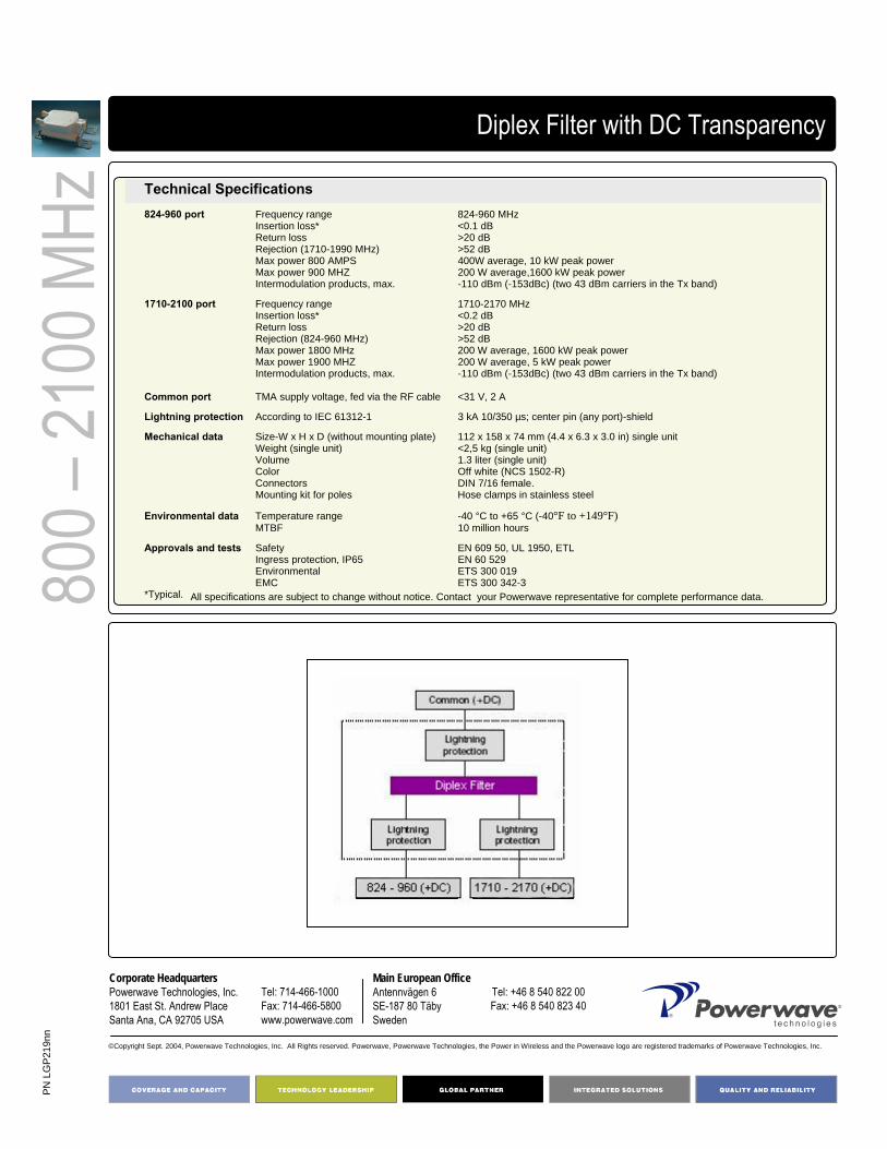
PN L
GP
219n
n
Corporate HeadquartersPowerwave Technologies, Inc. 1801 East St. Andrew PlaceSanta Ana, CA 92705 USA
Tel: 714-466-1000Fax: 714-466-5800 www.powerwave.com
Main European OfficeAntennvägen 6SE-187 80 TäbySweden
Tel: +46 8 540 822 00Fax: +46 8 540 823 40
©Copyright Sept. 2004, Powerwave Technologies, Inc. All Rights reserved. Powerwave, Powerwave Technologies, the Power in Wireless and the Powerwave logo are registered trademarks of Powerwave Technologies, Inc.
800 –
2100
MHz
Diplex Filter with DC Transparency
Technical Specifications824-960 port Frequency range 824-960 MHz
Insertion loss* <0.1 dBReturn loss >20 dBRejection (1710-1990 MHz) >52 dBMax power 800 AMPS 400W average, 10 kW peak powerMax power 900 MHZ 200 W average,1600 kW peak powerIntermodulation products, max. -110 dBm (-153dBc) (two 43 dBm carriers in the Tx band)
1710-2100 port Frequency range 1710-2170 MHzInsertion loss* <0.2 dBReturn loss >20 dBRejection (824-960 MHz) >52 dBMax power 1800 MHz 200 W average, 1600 kW peak powerMax power 1900 MHZ 200 W average, 5 kW peak powerIntermodulation products, max. -110 dBm (-153dBc) (two 43 dBm carriers in the Tx band)
Common port TMA supply voltage, fed via the RF cable <31 V, 2 A
Lightning protection According to IEC 61312-1 3 kA 10/350 µs; center pin (any port)-shield
Mechanical data Size-W x H x D (without mounting plate) 112 x 158 x 74 mm (4.4 x 6.3 x 3.0 in) single unitWeight (single unit) <2,5 kg (single unit)Volume 1.3 liter (single unit)Color Off white (NCS 1502-R)Connectors DIN 7/16 female. Mounting kit for poles Hose clamps in stainless steel
Environmental data Temperature range -40 °C to +65 °C (-40°F to +149°F)MTBF 10 million hours
Approvals and tests Safety EN 609 50, UL 1950, ETLIngress protection, IP65 EN 60 529Environmental ETS 300 019EMC ETS 300 342-3
*Typical. All specifications are subject to change without notice. Contact your Powerwave representative for complete performance data.
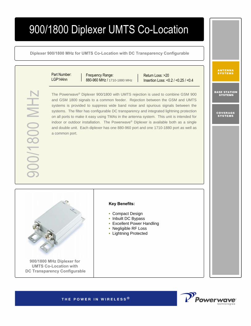
900/1
800 M
HzDiplexer 900/1800 MHz for UMTS Co-Location with DC Transparency Configurable
900/1800 Diplexer UMTS Co-Location
Part Number:LGP144nn
The Powerwave® Diplexer 900/1800 with UMTS rejection is used to combine GSM 900 and GSM 1800 signals to a common feeder. Rejection between the GSM and UMTS systems is provided to suppress wide band noise and spurious signals between the systems. The filter has configurable DC transparency and integrated lightning protection on all ports to make it easy using TMAs in the antenna system. This unit is intended for indoor or outdoor installation. The Powerwave® Diplexer is available both as a single and double unit. Each diplexer has one 880-960 port and one 1710-1880 port as well as a common port.
Key Benefits:
• Compact Design• Inbuilt DC Bypass• Excellent Power Handling• Negligible RF Loss• Lightning Protected
900/1800 MHz Diplexer forUMTS Co-Location with
DC Transparency Configurable
Frequency Range:880-960 MHz / 1710-1880 MHz
Return Loss: >20Insertion Loss: <0.2 / <0.25 / <0.4

PNLG
P144
nn
©Copyright September 2003, Powerwave Technologies, Inc. All Rights reserved. Powerwave, Powerwave Technologies, The Power in Wireless and the Powerwave logo are registered trademarks of Powerwave Technologies, Inc.
Corporate HeadquartersPowerwave Technologies, Inc. 1801 East St. Andrew PlaceSanta Ana, CA 92705 USA
Tel: 714-466-1000Fax: 714-466-5800 www.powerwave.com
Main European OfficeAntennvägen 6SE-187 80 TäbySwedenTel: +46 8 540 822 00Fax: +46 8 540 823 40
Hong Kong Office23 F Tai Yau Building181 Johnston RoadWanchai, Hong KongTel: +852 2512 6123Fax: +852 2575 4860
900/
1800
MHz
900/1800 Diplexer UMTS Co-Location
Electrical Specifications
880-960 Port Frequency range (MHz) 880-960Insertion Loss (dB) <0.2Return Loss (dB) >20Rejection GSM 1800 (dB) >55Rejection UMTS UL (dB) >64Rejection UMTS DL (dB) >44Average Power Handling (dBm) >80 W (>49)Peak Power Handling (dBm) >320 W (>55)IM 2Tx@43dBm (dBc) -153
1710-1880 Port Frequency range (MHz) 1710-1880Insertion Loss (dB) <0.25 dB in Rx, <0.4 dB in TxReturn Loss (dB) >20Rejection GSM 1800 (dB) >63Rejection UMTS UL (dB) >64Rejection UMTS DL (dB) >44Average Power Handling (dBm) >80 W (>49) Peak Power Handling (dBm) >320 W (>55)IM 2Tx@43dBm (dBc) -153
All specifications are subject to change without notice. Contact your Powerwave representative for complete performance data.
Mechanical Specifications
Size, WxHxD (without mounting plate) 136 x166 x63mm (5.5 x 6.5 x 2.51 in)Weight <3 kg (6.6 lbs)Color Off White (NCS 1502-R)Housing Aluminum, IP 65RF-connectors DIN 7/16 femaleMounting Kit Hose Clamps in Stainless SteelTemperature Range -40 oC to +65 oCMTBF >10 Million HoursLightning Protection On all ports, even DC isolatedSafety EN 60 950Ingress Protection EN 60 529Environmental ETS 300 019

1800
/2100
Diplexer for 1800/2100 with Configurable DC Transparency
1800/2100 Diplexer
Part Number:LGP145nn
The Powerwave® Diplexer 1800/2100 is to be used for combining GSM 1800 and UMTS 2100 signals to a common feeder. Rejection between the GSM and UMTS systems is provided to suppress wide band noise and spurious signals between the systems. The diplexer has a configurable DC path to provide both DC and modulated subcarriercommunication to TMA and RET systems over the feeder cable. This unit is intended for indoor or outdoor installations.
Powerwave vented enclosure design is deployed to prevent the effect of condensation thereby guaranteeing long reliable, maintenance free service in all environmental conditions.
Key Benefits:
• Compact Design• Inbuilt DC Transparency and
Subcarrier Support for Data Communication • Negligible Transmit Band Loss• Lightning Protected on All Ports• Full Band
1800/UMTS Diplexer
Frequency Range: 1710-1880 MHz / 1920-2170 MHz
Low Insertion Loss
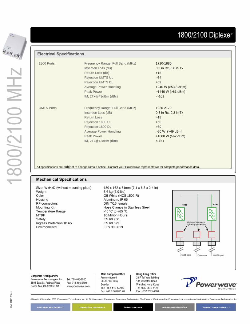
PNLG
P145
nn
©Copyright September 2003, Powerwave Technologies, Inc. All Rights reserved. Powerwave, Powerwave Technologies, The Power in Wireless and the Powerwave logo are registered trademarks of Powerwave Technologies, Inc.
Corporate HeadquartersPowerwave Technologies, Inc. 1801 East St. Andrew PlaceSanta Ana, CA 92705 USA
Tel: 714-466-1000Fax: 714-466-5800 www.powerwave.com
Main European OfficeAntennvägen 6SE-187 80 TäbySwedenTel: +46 8 540 822 00Fax: +46 8 540 823 40
Hong Kong Office23 F Tai Yau Building181 Johnston RoadWanchai, Hong KongTel: +852 2512 6123Fax: +852 2575 4860
1800
/2100
MHz
1800/2100 Diplexer
Electrical Specifications
All specifications are subject to change without notice. Contact your Powerwave representative for complete performance data.
Mechanical Specifications
Size, WxHxD (without mounting plate) 180 x 162 x 61mm (7.1 x 6.3 x 2.4 in)Weight 3.6 kg (7.9 lbs)Color Off White (NCS 1502-R)Housing Aluminum, IP 65RF-connectors DIN 7/16 femaleMounting Kit Hose Clamps in Stainless SteelTemperature Range -40 oC to +65 oCMTBF 10 Million HoursSafety EN 60 950Ingress Protection IP 65 EN 60 529Environmental ETS 300 019
1920-21700.5 in Rx, 0.3 in Tx>18>60>60>80 W (>49 dBm)>1600 W (>62 dBm)<-161
Frequency Range, Full Band (MHz)Insertion Loss (dB) Return LossRejection 1800 ULRejection 1800 DLAverage Power HandlingPeak PowerIM, 2Tx@43dBm (dBc)
UMTS Ports
1710-18800.3 in Rx, 0.6 in Tx>18>74>59>240 W (>53.8 dBm)>1440 W (>61 dBm)<-161
Frequency Range, Full Band (MHz)Insertion Loss (dB) Return Loss (dB) Rejection UMTS ULRejection UMTS DLAverage Power Handling Peak PowerIM, 2Tx@43dBm (dBc)
1800 Ports

900/1
800/2
100 M
HzTriplex Filter for 900, 1800 MHz and UMTS with DC Transparency
Triplexer Fullband
Part Number:LGP141nn
Powerwave® offers a variety of multiband filters for installation in 3G networks. The filters enable re-use of existing feeders in order to reduce cost of new installations and simplifies the process of getting necessary site permissions for the new installations. It is designed for outdoor use and intended for co-siting of base stations to enable sharing of feeder, TMA system and antenna. The unit can be used both at the BTS end for combining frequency bands to a common port and at the antenna end for splitting the frequency bands to separate antennas. The filter has configurable DC transparency and integrated lightning protection on all ports to make it easy using TMAs in the antenna system.
Key Benefits:
• Compact Design• Inbuilt DC Transparency and
Subcarrier Support• Superior Power Handling• Negligible Transmit Band Loss• Lightning Protected• Full Band
Triplex Filter for 900, 1800 MHzand UMTS with DC Transparency
Frequency Range: 880-960 MHz / 1710-1880 MHz / 1920-2170 MHz
Return Loss: >20 dBInsertion Loss: <0.2 / <0.3 / <0.5

PNLG
P141
nn
©Copyright September 2003, Powerwave Technologies, Inc. All Rights reserved. Powerwave, Powerwave Technologies, The Power in Wireless and the Powerwave logo are registered trademarks of Powerwave Technologies, Inc.
Corporate HeadquartersPowerwave Technologies, Inc. 1801 East St. Andrew PlaceSanta Ana, CA 92705 USA
Tel: 714-466-1000Fax: 714-466-5800 www.powerwave.com
Main European OfficeAntennvägen 6SE-187 80 TäbySwedenTel: +46 8 540 822 00Fax: +46 8 540 823 40
Hong Kong Office23 F Tai Yau Building181 Johnston RoadWanchai, Hong KongTel: +852 2512 6123Fax: +852 2575 4860
900/1
800/2
100 M
HzTriplexer Fullband
Technical Specifications
Product number LGP141nn900 Port Frequency range, full band (MHz) 880-960
Insertion Loss (dB) <0.2Return Loss (dB) >20Average Power Handling (dBm) >200 W (>53)Peak Power (dBm) >1600 W (>62)Intermodulation Products, Max <-116 dBm @2x43 dBm in Tx-band
1800 Port Frequency range,full band (MHz) 1710-1880Insertion loss (dB) <0.3 dB in Rx, <0.6 dB in TxReturn loss (dB) >20Average Power Handling >200 W (>53 dBm)Peak Power >1600 W (>62 dBm)Intermodulation Products, Max <-116 dBm @2x43 dBm Tx-band
UMTS Port Frequency Range, Full Band (MHz) 1920-2170Insertion Loss (dB) <0.5 dB in Rx, <0.3 dB in TxReturn Loss (dB) >20 dBAverage Power Handling (dBm) >80 W (>-49 dBm)Peak Power (dBm) >1600 W (>62 dBm)Intermoducation Products, Max <-116 dBm @2Tx43 dBm in Tx-band
Common Port Peak Power >6400 W (>68 dBm)
Isolation Between Ports Rejection Between Ports (except common) >50 dB
All specifications are subject to change without notice. Contact your Powerwave representative for complete performance data.
Mechanical Specifications
Size, WxHxD (without mounting plate) 169 x 228 x 68mm (6.7 x 9.0 x 2.7 in)Weight <3.0 kg (6.5 lbs)Color Off White (NCS 1502-R)Housing Aluminum, IP 65 (Option IP 68)RF-connectors DIN 7/16 femaleMounting Kit Hose Clamps in Stainless SteelTemperature Range -40 oC to +65 oCMTBF >10 Million HoursSafety EN 60 950, UL 60 950, ETLIngress Protection, IP 65 EN 60 529Environmental ETS 300 019

890-
960 M
HzCo-Location Filter GSM900
Co-Location Filter 900
Part Number:LGP195nn
The Powerwave® Co-location filter for GSM900 provides attenuation of 800MHz transmitters in order not to degrade the GSM900 uplink. The unit comes in three different versions depending on carrier allocations.
The duplexed design enables external installation on Rx/Tx systems.
Key Benefits:
• Compact Design• Excellent Power Handling• Duplexed Design for Rx/Tx
Co-Location Filter 900 MHz
Frequency Range:890-915 MHz / 896-915 MHz
Return Loss: >18 dBInsertion Loss: <1.5dB/ <1.0 / <0.5dB
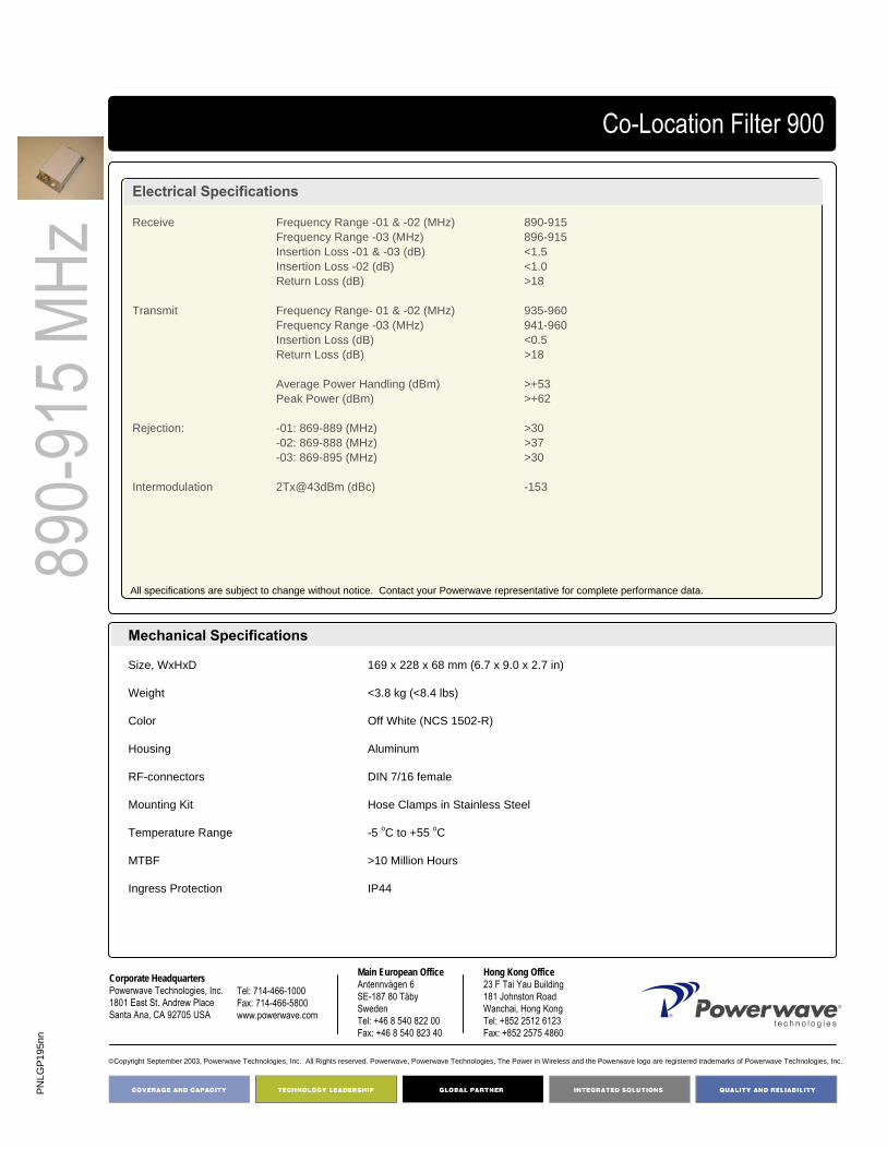
PNLG
P195
nn
©Copyright September 2003, Powerwave Technologies, Inc. All Rights reserved. Powerwave, Powerwave Technologies, The Power in Wireless and the Powerwave logo are registered trademarks of Powerwave Technologies, Inc.
Corporate HeadquartersPowerwave Technologies, Inc. 1801 East St. Andrew PlaceSanta Ana, CA 92705 USA
Tel: 714-466-1000Fax: 714-466-5800 www.powerwave.com
Main European OfficeAntennvägen 6SE-187 80 TäbySwedenTel: +46 8 540 822 00Fax: +46 8 540 823 40
Hong Kong Office23 F Tai Yau Building181 Johnston RoadWanchai, Hong KongTel: +852 2512 6123Fax: +852 2575 4860
890-
915 M
HzCo-Location Filter 900
Electrical Specifications
Receive Frequency Range -01 & -02 (MHz) 890-915Frequency Range -03 (MHz) 896-915Insertion Loss -01 & -03 (dB) <1.5Insertion Loss -02 (dB) <1.0Return Loss (dB) >18
Transmit Frequency Range- 01 & -02 (MHz) 935-960Frequency Range -03 (MHz) 941-960Insertion Loss (dB) <0.5Return Loss (dB) >18
Average Power Handling (dBm) >+53Peak Power (dBm) >+62
Rejection: -01: 869-889 (MHz) >30-02: 869-888 (MHz) >37-03: 869-895 (MHz) >30
Intermodulation 2Tx@43dBm (dBc) -153
All specifications are subject to change without notice. Contact your Powerwave representative for complete performance data.
Mechanical Specifications
Size, WxHxD 169 x 228 x 68 mm (6.7 x 9.0 x 2.7 in)
Weight <3.8 kg (<8.4 lbs)
Color Off White (NCS 1502-R)
Housing Aluminum
RF-connectors DIN 7/16 female
Mounting Kit Hose Clamps in Stainless Steel
Temperature Range -5 oC to +55 oC
MTBF >10 Million Hours
Ingress Protection IP44
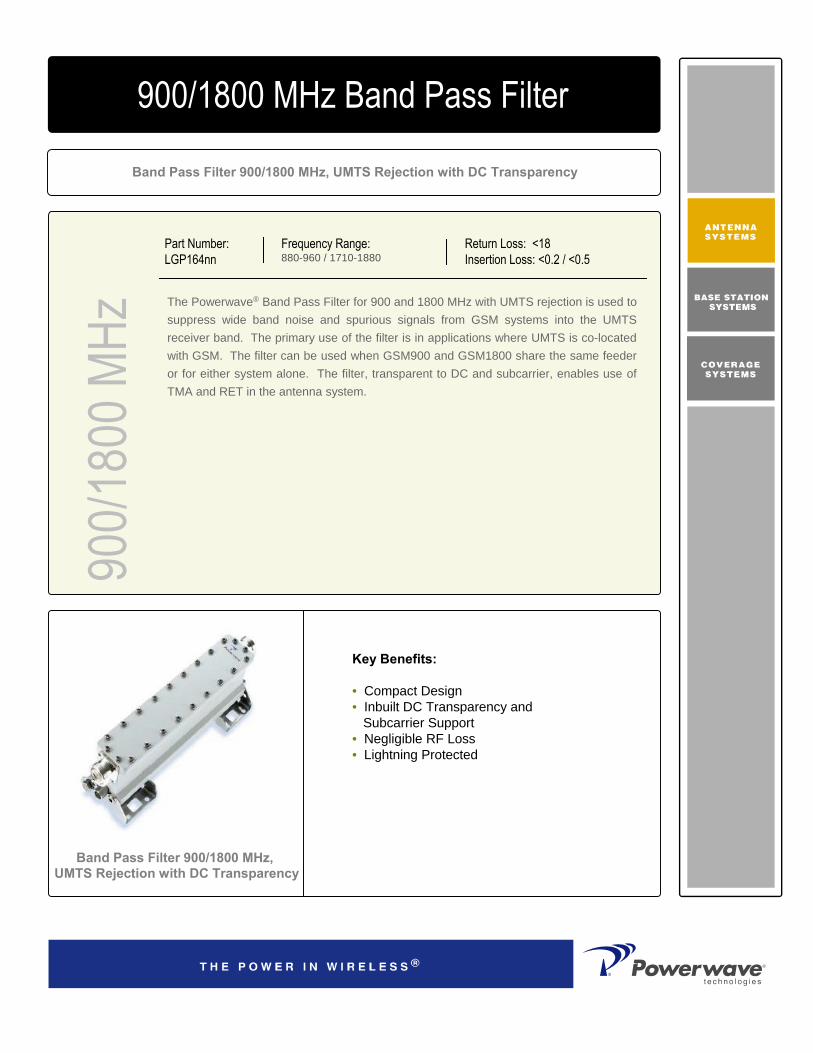
900/1
800 M
HzBand Pass Filter 900/1800 MHz, UMTS Rejection with DC Transparency
900/1800 MHz Band Pass Filter
Part Number:LGP164nn
The Powerwave® Band Pass Filter for 900 and 1800 MHz with UMTS rejection is used to suppress wide band noise and spurious signals from GSM systems into the UMTS receiver band. The primary use of the filter is in applications where UMTS is co-located with GSM. The filter can be used when GSM900 and GSM1800 share the same feeder or for either system alone. The filter, transparent to DC and subcarrier, enables use of TMA and RET in the antenna system.
Key Benefits:
• Compact Design• Inbuilt DC Transparency and
Subcarrier Support • Negligible RF Loss• Lightning Protected
Band Pass Filter 900/1800 MHz,UMTS Rejection with DC Transparency
Frequency Range: 880-960 / 1710-1880
Return Loss: <18Insertion Loss: <0.2 / <0.5

PNLG
P164
nn
©Copyright September 2003, Powerwave Technologies, Inc. All Rights reserved. Powerwave, Powerwave Technologies, The Power in Wireless and the Powerwave logo are registered trademarks of Powerwave Technologies, Inc.
Corporate HeadquartersPowerwave Technologies, Inc. 1801 East St. Andrew PlaceSanta Ana, CA 92705 USA
Tel: 714-466-1000Fax: 714-466-5800 www.powerwave.com
Main European OfficeAntennvägen 6SE-187 80 TäbySwedenTel: +46 8 540 822 00Fax: +46 8 540 823 40
Hong Kong Office23 F Tai Yau Building181 Johnston RoadWanchai, Hong KongTel: +852 2512 6123Fax: +852 2575 4860
900/1
800 M
Hz900/1800 Band Pass Filter
Electrical Specifications
Frequency Range (MHz) 880-960 / 1710-1880Insertion Loss (800-960 MHz) (dB) <0.2Insertion Loss (1710-1880 MHz) (dB) <0.5Return Loss (dB) >18Rejection UMTS (dB) >60Average Power Handling (dBm) >80 W (>49)Peak Power (dBm) >320 W (>55)IM 2Tx@43dBm (dBc) -161
All specifications are subject to change without notice. Contact your Powerwave representative for complete performance data.
Mechanical Specifications
Size, WxHxD 255 x 75 x 50mm (10.0 x 3.0 x 2.0 in)Weight <1.4 kg (3.1 lbs)Color Off White (NCS 1502-R)Housing Aluminum, IP 65RF-connectors DIN 7/16 femaleMounting Kit Hose Clamps in Stainless SteelTemperature Range -40 oC to +65 oCMTBF >10 Million HoursSafety EN 60 950Ingress Protection EN 60 529Environmental ETS 300 019
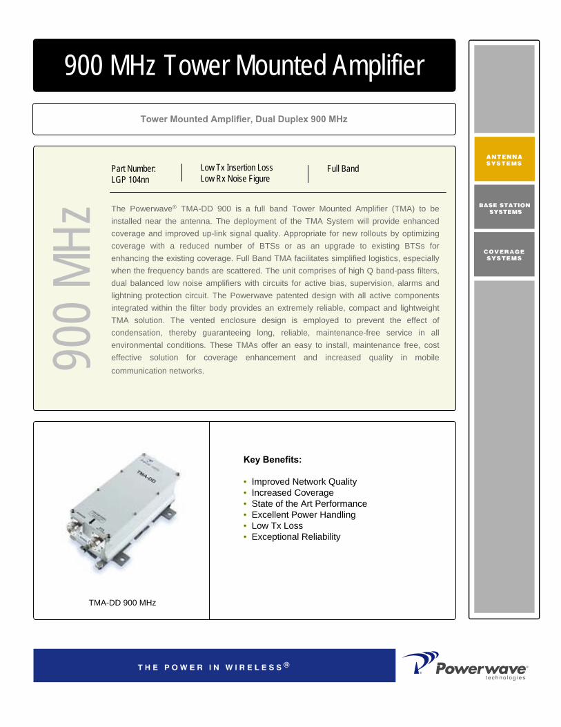
900 M
Hz
The Powerwave® TMA-DD 900 is a full band Tower Mounted Amplifier (TMA) to be installed near the antenna. The deployment of the TMA System will provide enhanced coverage and improved up-link signal quality. Appropriate for new rollouts by optimizing coverage with a reduced number of BTSs or as an upgrade to existing BTSs for enhancing the existing coverage. Full Band TMA facilitates simplified logistics, especially when the frequency bands are scattered. The unit comprises of high Q band-pass filters, dual balanced low noise amplifiers with circuits for active bias, supervision, alarms and lightning protection circuit. The Powerwave patented design with all active components integrated within the filter body provides an extremely reliable, compact and lightweight TMA solution. The vented enclosure design is employed to prevent the effect of condensation, thereby guaranteeing long, reliable, maintenance-free service in all environmental conditions. These TMAs offer an easy to install, maintenance free, cost effective solution for coverage enhancement and increased quality in mobile communication networks.
Tower Mounted Amplifier, Dual Duplex 900 MHz
900 MHz Tower Mounted Amplifier
Key Benefits:
• Improved Network Quality• Increased Coverage• State of the Art Performance• Excellent Power Handling• Low Tx Loss• Exceptional Reliability
TMA-DD 900 MHz
Part Number:LGP 104nn
Low Tx Insertion LossLow Rx Noise Figure
Full Band

D03
1-08
214
Rev
A
Corporate HeadquartersPowerwave Technologies, Inc. 1801 East St. Andrew PlaceSanta Ana, CA 92705 USA
Tel: 714-466-1000Fax: 714-466-5800 www.powerwave.com
Main European OfficeAntennvägen 6SE-187 80 TäbySwedenTel: +46 8 540 822 00Fax: +46 8 540 823 40
Main Asia Pacific Office23 F Tai Yau Building181 Johnston RoadWanchai, Hong KongTel: +852 2512 6123Fax: +852 2575 4860
©Copyright September 2003, Powerwave Technologies, Inc. All Rights reserved. Powerwave, Powerwave Technologies, The Power in Wireless and the Powerwave logo are registered trademarks of Powerwave Technologies, Inc.
900 M
Hz900 MHz Tower Mounted Amplifier
Technical Specifications
Product Number LGP104nnUp-link Frequency range, full band (25 MHz) 890-915
Nominal gain (dB) 12Return Loss (dB) >16Noise figure* (dB) <1.7 Output 3rd order Intercept Point (OIP3)* dBm >+25
Down-link Frequency range,full band (25 MHz) 935-960Insertion loss* (dB) 0.35 Return loss (dB) >18
Intermodulation 2 Tx@x43 dBm (dBc) <-159Alarm Functionality Two levels,individually supervised LNAsPower Consumption @12 VDC 1.5 W per LNA
* TypicalAll specifications subject to change without notice. Contact your Powerwave representative for complete performance data.
Mechanical Specifications
Size,W x H x D (without mounting plate) 109 x 284 x 127 mm (4.3 x 11.2 x 5.0 in)Weight <5.6 kg (12.3 lbs)Color Off white (NCS 1502-R)Housing AluminumRF-connectors DIN 7/16 female. Mounting kit Mounting kit for pole and wall is included. Temperature range -40 °C to +65 °C (-40 °F to +149 °F) MTBF >1 million hoursSafety EN 60 950Ingress protection, IP 65 EN 60 529Environmental ETS 300 019EMC ETS 300 342-3

GS
M 9
00 M
Hz
The Powerwave® TMA-DD GSM 900 is a extended band Tower Mounted Amplifier (TMA)
to be installed near the antenna. Deployed in a GSM, GPRS and EDGE network it will
increase capacity and coverage as well as extend the battery life time for the handsets.
TMA System will provide enhanced coverage and improved up-link signal quality.
Appropriate for new rollouts by optimizing coverage with a reduced number of BTSs or as
an upgrade to existing BTSs for enhancing the existing coverage.
Extended Band TMA facilitates simplified logistics, especially when the frequency bands
are scattered. The unit comprises of high Q band-pass filters, dual balanced low noise
amplifiers with circuits for active bias, supervision, alarms and lightning protection circuit.
The Powerwave patented design with all active components integrated within the filter
body provides an extremely reliable, compact and lightweight TMA solution. The vented
enclosure design is employed to prevent the effect of condensation, thereby guaranteeing
long, reliable, maintenance-free service in all environmental conditions. These TMAs offer
an easy to install, maintenance free, cost effective solution for coverage enhancement
and increased quality in mobile communication networks.
Dual Duplex GSM 900 MHz Extended Band
900 MHz Tower Mounted Amplifier
Key Benefits:
• Improved Network Quality• Increased Coverage• Compact Design• State of the Art Performance• Excellent Power Handling• Low Tx Loss• Exceptional Reliability
Part Number:
LGP 166nn
Up-link: 887-915 MHz
Down-link: 932-960 MHz
Gain: 12 dB
Noise Figure: < 1.7 dB

PN
LGP
104n
n
Corporate Headquarters
Powerwave Technologies, Inc. 1801 East St. Andrew Place
Santa Ana, CA 92705 USA
Tel: 714-466-1000
Fax: 714-466-5800 www.powerwave.com
Main European Office
Antennvägen 6
SE-187 80 TäbySweden
Tel: +46 8 540 822 00Fax: +46 8 540 823 40
Hong Kong Office
23 F Tai Yau Building
181 Johnston RoadWanchai, Hong Kong
Tel: +852 2512 6123Fax: +852 2575 4860
©Copyright September 2003, Powerwave Technologies, Inc. All Rights reserved. Powerwave, Powerwave Technologies, The Power in Wireless and the Powerwave logo are registered trademarks of Powerwave Technologies, Inc.
GS
M 9
00M
Hz
Tower Mounted Amplifier
Technical Specifications
Product Number LGP166nnUp-link Frequency range, Extended band (28 MHz) 887-915
Nominal gain (dB) 12Return loss* (dB) > 20Noise figure* (dB) < 1.7 Output 3rd order Intercept Point* (dBm) > +23
Down-link Frequency range,full band (28 MHz) 932-960Insertion loss* (dB) < 0.7Return loss* (dB) > 20
Intermodulation 2 Tx@x43 dBm (dBc) <-158
Alarm Functionality Two levels,individually supervised LNAsPower Consumption @12 VDC 1.2 W per LNA
* Typical
All specifications subject to change without notice. Contact your Powerwave representative for complete performance data.
Mechanical Specifications
Size,W x H x D (without mounting plate) 169 x 228 x 66 mm (6.6 x 9 x 2.6 in)Weight 5.7 kg (12.3 lbs)Color Off white (NCS 1502-R)Housing AluminumRF-connectors DIN 7/16 female. Mounting kit Mounting kit for pole and wall is included. Temperature range -40 °C to +65 °C (-40 °F to +149 °F) MTBF >1 million hoursSafety EN 60 950Ingress protection, IP 65 EN 60 529Environmental ETS 300 019EMC ETS 300 342-3

EG
SM
900
MH
z
The Powerwave® TMA-DD EGSM 900 is a full band Tower Mounted Amplifier (TMA) to
be installed near the antenna. Deployed in a GSM, GPRS and EDGE network it will
increase capacity and coverage as well as extend the battery life time for the handsets.
TMA System will provide enhanced coverage and improved up-link signal quality.
Appropriate for new rollouts by optimizing coverage with a reduced number of BTSs or as
an upgrade to existing BTSs for enhancing the existing coverage.
Full Band TMA facilitates simplified logistics, especially when the frequency bands are
scattered. The unit comprises of high Q band-pass filters, dual balanced low noise
amplifiers with circuits for active bias, supervision, alarms and lightning protection circuit.
The Powerwave patented design with all active components integrated within the filter
body provides an extremely reliable, compact and lightweight TMA solution. The vented
enclosure design is employed to prevent the effect of condensation, thereby guaranteeing
long, reliable, maintenance-free service in all environmental conditions. These TMAs offer
an easy to install, maintenance free, cost effective solution for coverage enhancement
and increased quality in mobile communication networks.
Dual Duplex EGSM 900 MHz Full Band
900 MHz Tower Mounted Amplifier
Key Benefits:
• Improved Network Quality• Increased Coverage• Compact Design• State of the Art Performance• Excellent Power Handling• Low Tx Loss• Exceptional Reliability
Part Number:
LGP 192nn
Up-link: 880-915 MHz
Down-link: 925-960 MHz
Gain: 12 dB
Noise Figure: < 1.7 dB
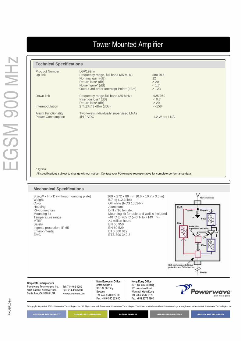
PN
LGP
104n
n
Corporate Headquarters
Powerwave Technologies, Inc. 1801 East St. Andrew Place
Santa Ana, CA 92705 USA
Tel: 714-466-1000
Fax: 714-466-5800 www.powerwave.com
Main European Office
Antennvägen 6
SE-187 80 TäbySweden
Tel: +46 8 540 822 00Fax: +46 8 540 823 40
Hong Kong Office
23 F Tai Yau Building
181 Johnston RoadWanchai, Hong Kong
Tel: +852 2512 6123Fax: +852 2575 4860
©Copyright September 2003, Powerwave Technologies, Inc. All Rights reserved. Powerwave, Powerwave Technologies, The Power in Wireless and the Powerwave logo are registered trademarks of Powerwave Technologies, Inc.
EG
SM
900
MH
z
Tower Mounted Amplifier
Technical Specifications
Product Number LGP192nnUp-link Frequency range, full band (35 MHz) 880-915
Nominal gain (dB) 12Return loss* (dB) > 20Noise figure* (dB) < 1.7 Output 3rd order Intercept Point* (dBm) > +23
Down-link Frequency range,full band (35 MHz) 925-960Insertion loss* (dB) < 0.7Return loss* (dB) > 20
Intermodulation 2 Tx@x43 dBm (dBc) <-158
Alarm Functionality Two levels,individually supervised LNAsPower Consumption @12 VDC 1.2 W per LNA
* Typical
All specifications subject to change without notice. Contact your Powerwave representative for complete performance data.
Mechanical Specifications
Size,W x H x D (without mounting plate) 169 x 272 x 89 mm (6.6 x 10.7 x 3.5 in)Weight 5.7 kg (12.3 lbs)Color Off white (NCS 1502-R)Housing AluminumRF-connectors DIN 7/16 female. Mounting kit Mounting kit for pole and wall is included. Temperature range -40 °C to +65 °C (-40 °F to +149 °F) MTBF >1 million hoursSafety EN 60 950Ingress protection, IP 65 EN 60 529Environmental ETS 300 019EMC ETS 300 342-3

1800
MHz
The Powerwave® Twin TMA-DD 1800 consists of two full band Tower Mounted Amplifiers (TMA) to be installed near the antenna. The Twin contains TMAs for both main and diversity paths and fits perfectly with cross-pole antennas. With a volume of only 2.9 litres it is extremely small and compact. Deployed in a GSM, EDGE, CDMA or WCDMA (CDMA 2000 or UMTS) network it will increase capacity and coverage as well as extend the battery life time for the handsets.
Full Band TMA facilitates simplified logistics, especially when the frequency bands are scattered. The unit comprises of high Q band-pass filters, dual balanced low noise amplifiers with circuits for active bias, supervision, alarms and lightning protection circuit. The Powerwave patented design with all active components integrated within the filter body provides an extremely reliable, compact and lightweight TMA solution.
The Powerwave® unique field proven reliability secures a long maintenance free
service in all environmental conditions.
Twin Dual Duplex 1800 MHz Full Band
Twin Tower Mounted Amplifier
Key Benefits:
• World Leading Compact Design, two TMAsin One Unit
• Full Band Design for Scattered Blocks of Frequencies
• Low Noise Figure for Increased Coverage and Improved Network Quality
• Low Tx Insertion Loss • Exceptional Reliability
Part Number:LGP 185nn
Up-link: 1710-1785 MHzDown-link: 1805-1880 MHz
Gain: 12 dBNoise Figure: 1.5 dB

D03
1-08
219
Rev
A
Corporate HeadquartersPowerwave Technologies, Inc. 1801 East St. Andrew PlaceSanta Ana, CA 92705 USA
Tel: 714-466-1000Fax: 714-466-5800 www.powerwave.com
Main European OfficeAntennvägen 6SE-187 80 TäbySwedenTel: +46 8 540 822 00Fax: +46 8 540 823 40
Main Asia Pacific Office23 F Tai Yau Building181 Johnston RoadWanchai, Hong KongTel: +852 2512 6123Fax: +852 2575 4860
©Copyright September 2003, Powerwave Technologies, Inc. All Rights reserved. Powerwave, Powerwave Technologies, The Power in Wireless and the Powerwave logo are registered trademarks of Powerwave Technologies, Inc.
1800
MHz
Twin Tower Mounted Amplifier
Technical Specifications
Product number LGP185nnUp-link Frequency range, full band (75 MHz) 1710-1880 MHz
Nominal gain (dB) 12Noise figure* (dB) 1.5Output 3rd order Intercept Point* (dBm) +26Bypass functionality Optional
Down-link Frequency range,full band (75 MHz) 1805-1880 MHzInsertion loss* (dB) 0.4Return loss (dB) >18
Intermodulation @ 2 x 43 dBm Tx carriersIn receive band <-116 dBm, referred to Antenna port
Alarm functionality Two levels,individually supervised LNAsPower consumption @12 VDC 1.5 W per LNAMechanical data Size,W x H x D (without mounting plate) 169 x 272.5 x 67.7 mm (6.7 x 10.7 x 2.7 in)
Weight <4.5 kg (9.9 lbs)Colour Off white (NCS 1502-R)Housing AluminiumRF-connectors DIN 7/16 female. Mounting kit Mounting kit for pole and wall is included.
.Environmental data Temperature range -40 °C to +65 °C
MTBF >1 million hoursApprovals and tests Safety EN 60 950
Ingress protection, IP 65 EN 60 529Environmental ETS 300 019EMC ETS 301 489
Optional AISG compatibility AISG 1.1
* TypicalAll specifications subject to change without notice. Contact your Powerwave representative for complete performance data.
Rev 0.1

D03
1-08
222
Rev
A
2100
MHz
Micro Twin™ Tower Mounted Amplifier Dual Duplex 2100 MHz Full Band
Micro Twin™ TMA
The new Powerwave Micro Twin™ 2100 is less than half the size than present conventional designs. With a volume of only 1.4 liters, it is extremely small and compact. It consists of two full band Tower Mounted Amplifiers (TMA) in one housing to be installed near the antenna. The Twin contains TMAs for both the main and diversity branch and fits perfectly with cross-pole antennas. Deployed in a 2100 network it will increase capacity and coverage as well as extend battery-life for handsets. The Micro Twin™ is AISG compatible with automatic current alarm fall back to support installations with current alarm supervision.
Full Band TMA facilitates simplified logistics, especially when the frequency bands are scattered. The unit comprises of high Q band-pass filters, dual balanced low noise amplifiers with circuits for active bias, supervision, alarms and lightning protection circuit. The Powerwave patented design with all active components integrated within the filter body provides an extremely reliable, compact and lightweight TMA solution
The Powerwave unique field proven reliability secures a long maintenance-free service in all environmental conditions
Key Benefits:
• World Leading Compact Design, twoTMAs in One Unit
• Low Noise Figure for Increased Coverage and Improved Network Quality
• Low Tx Insertion Loss • Exceptional Reliability• Compatible With Most Node B Systems• AISG Compatible
Up-link: 1920-1980 MHzDown-link: 2110-2170 MHz
Part Number:LGP215nn
Gain: 12 dB, fixed or 23-32 dB variable gainNoise Figure: 1.4 dB
Micro Twin™Tower Mounted Amplifier
Dual Duplex 2100 MHz Full Band

D03
1-08
222
Rev
A
Corporate HeadquartersPowerwave Technologies, Inc. 1801 East St. Andrew PlaceSanta Ana, CA 92705 USA
Tel: 714-466-1000Fax: 714-466-5800 www.powerwave.com
Main European OfficeAntennvägen 6SE-187 80 TäbySwedenTel: +46 8 540 822 00Fax: +46 8 540 823 40
©Copyright March 2005, Powerwave Technologies, Inc. All Rights reserved. Powerwave, Powerwave Technologies, The Power in Wireless and the Powerwave logo are registered trademarks of Powerwave Technologies, Inc.
Main Asia Pacific Office23 F Tai Yau Building181 Johnston RoadWanchai, Hong KongTel: +852 2512 6123Fax: +852 2575 4860
2100
MHz
Micro Twin™ TMA
Technical Specifications
Product number LGP215nnUp-link Frequency range, full band (60 MHz) 1920-1980 MHz
Nominal gain (dB) 12 dB, fixed or 23-32 dB variable gainNoise figure* (dB) 1.4Output 3rd order Intercept Point (dBm)* +25Bypass loss* (dB) <2.0 dB (12 dB variant)
Down-link Frequency range,full band (60 MHz) 2110-2170 MHzInsertion loss* 0.3 dBReturn loss >20 dB
Intermodulation @ 2 x 43 dBm Tx carriersIn receive band <-125 dBm, referred to Antenna port
Alarm functionality AISG CompatiblePower consumption @12 VDC 1.5 W per LNA
Powerwave is an active member of the 3GPP and Antenna interface Standard Group
*TypicalAll specifications are subject to change without notice. Contact your Powerwave representative for complete performance data.
Mechanical Specifications
Size,W x H x D (without mounting plate) 154 x 192 x 50 mm (6.0 x 7.5 x 2.0 in)Weight <3.5 kg (7.7 lbs) Color Off white (NCS 1502-R)RF-connectors DIN 7/16 female. Mounting kit Mounting kit for pole and wall is included. Temperature range -40 °C to +65 °CMTBF >1 million hours (over 100 years)Safety EN 60 950Ingress protection, IP 65 and IP 67 EN 60 529Environmental ETS 300 019EMC ETSI 125 113

D03
1-08
407
Rev
. A
Pg
1 of
2
Current Injector Broadband
The Powerwave® CIN ID is a Current Injector for indoor use. The CIN is to be mounted indoor close to the base station antenna ports and provides the ability to apply DC power to, and convey alarm conditions from, a Tower Mounted Amplifier via the coaxial feeder cable. It also supports AISG/3GPP data communication.
The unit features advanced lightning protection circuits acting as surge protection for the BTS. This eliminates the need for traditional lightning arresters in the BTS. DC supply cables are available in standard lengths with various connectors according to requirements.
The broadband design covers 800/900/1800/1900/2100 MHz frequency bands. Standard connector gender configuration is male to the BTS port and female to the antenna port. A version with reversed gender configuration is also available.
Key Benefits:
• Broadband design• Negligible insertion loss• Integrated lightning protection• Robust design• AISG/3GPP compatible
Indoor Current Injector
Part Number:LGP233nn
Frequency Range:806-960 and 1710-2170 MHz
Return Loss: >20dBInsertion Loss: <0.1dB
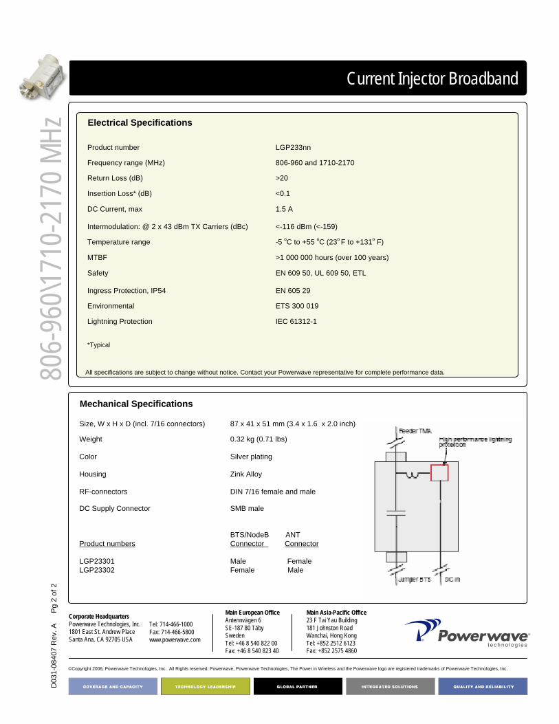
Corporate HeadquartersPowerwave Technologies, Inc. 1801 East St. Andrew PlaceSanta Ana, CA 92705 USA
Tel: 714-466-1000Fax: 714-466-5800 www.powerwave.com
Main European OfficeAntennvägen 6SE-187 80 TäbySwedenTel: +46 8 540 822 00Fax: +46 8 540 823 40
©Copyright 2006, Powerwave Technologies, Inc. All Rights reserved. Powerwave, Powerwave Technologies, The Power in Wireless and the Powerwave logo are registered trademarks of Powerwave Technologies, Inc.
Main Asia-Pacific Office23 F Tai Yau Building181 Johnston RoadWanchai, Hong KongTel: +852 2512 6123Fax: +852 2575 4860
D03
1-08
407
Rev
. A
Pg
2 of
2
Current Injector Broadband
Electrical Specifications
Mechanical Specifications
LGP233nnProduct number
*Typical
-5 oC to +55 oC (23o F to +131o F)Temperature range
>1 000 000 hours (over 100 years)MTBF
EN 609 50, UL 609 50, ETL
EN 605 29
Safety
Ingress Protection, IP54
ETS 300 019Environmental
IEC 61312-1Lightning Protection
1.5 A
<-116 dBm (<-159)
DC Current, max
Intermodulation: @ 2 x 43 dBm TX Carriers (dBc)
<0.1Insertion Loss* (dB)
>20Return Loss (dB)
806-960 and 1710-2170Frequency range (MHz)
SMB male
BTS/NodeB ANTConnector Connector
Male FemaleFemale Male
DC Supply Connector
Product numbers
LGP23301LGP23302
DIN 7/16 female and maleRF-connectors
Zink AlloyHousing
Silver platingColor
0.32 kg (0.71 lbs)Weight
87 x 41 x 51 mm (3.4 x 1.6 x 2.0 inch)Size, W x H x D (incl. 7/16 connectors)
All specifications are subject to change without notice. Contact your Powerwave representative for complete performance data. 806-
960\1
710-
2170
MHz

Current Injector Broadband
The Powerwave® CIN OD is a Current Injector for outdoor use. The Current Injector provides the ability to apply DC power to, and convey alarm conditions from, a Tower Mounted Amplifier via the coaxial feeder cable. It also supports AISG / 3GPP data communication.
The unit features advanced lightning protection circuits acting as surge protection for the BTS. This eliminates the need for traditional lightning arresters in the BTS. DC supply cables are available in standard lengths with various connectors according to requirements.
The broadband design covers 800/900/1800/1900/2100 MHz frequency bands. Standard connector gender configuration is male to the BTS port and female to the antenna port. A version with reversed gender configuration is also available.
Key Benefits:
• Broadband design• Negligible Insertion Loss• Integrated Lightning Protection• Robust Design• AISG/3GPP compatible
Outdoor Current Injector
Part Number:LGP213nn
Frequency Range:806-960 and 1710-2170 MHz
Return Loss: >20 dBInsertion Loss: <0.1 dB
D03
1-08
406
Rev
. A
Pg
1 of
2

Corporate HeadquartersPowerwave Technologies, Inc. 1801 East St. Andrew PlaceSanta Ana, CA 92705 USA
Tel: 714-466-1000Fax: 714-466-5800 www.powerwave.com
Main European OfficeAntennvägen 6SE-187 80 TäbySwedenTel: +46 8 540 822 00Fax: +46 8 540 823 40
©Copyright 2006, Powerwave Technologies, Inc. All Rights reserved. Powerwave, Powerwave Technologies, The Power in Wireless and the Powerwave logo are registered trademarks of Powerwave Technologies, Inc.
Main Asia-Pacific Office23 F Tai Yau Building181 Johnston RoadWanchai, Hong KongTel: +852 2512 6123Fax: +852 2575 4860
806-
960/1
710-
2170
MHz
Current Injector Broadband
Electrical Specifications
Mechanical Specifications
LGP213nnProduct Number
<-116 dBm (<-159)Intermodulation: @ 2x 43 dBm Tx carriers (dBc)
-40 oC to +65 oC (-40o F to +149o F)Temperature range
>1 000 000 hoursMTBF
EN 609 50, UL 60950, ETLSafety
EN 60 529Ingress protection, IP 68
ETS 300 019Environmental
IEC 61312-1Lightning Protection
*Typical
< 0.1
1.5 A
Insertion Loss* (dB)
DC Current, max
>20Return Loss (dB)
806 - 960MHz and 1710-2170Frequency range, 2 variants (MHz)
DIN 7/16 female and male
SMA female
BTS/NodeB ANTConnector Connector
Male FemaleFemale Male
RF-connectors
DC-connector
Product number
LGP21301LGP21302
AluminumHousing
Off-white, NCS 1502R Color
0.32 kg (0.71 lbs)Weight
87 x 41 x 51 mm (3.4 x 1.6 x 2.0 in)Size, W x H x D (incl. 7/16 connectors)
All specifications are subject to change without notice. Contact your Powerwave representative for complete performance data.
D03
1-08
406
Rev
. A
Pg
2 of
2
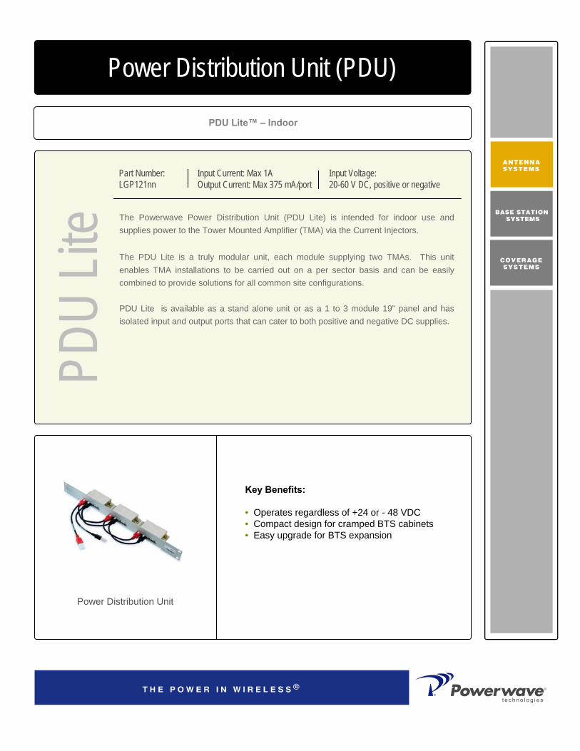
PDU Lite™ – Indoor
Power Distribution Unit (PDU)
Part Number:LGP121nn
The Powerwave Power Distribution Unit (PDU Lite) is intended for indoor use and supplies power to the Tower Mounted Amplifier (TMA) via the Current Injectors.
The PDU Lite is a truly modular unit, each module supplying two TMAs. This unitenables TMA installations to be carried out on a per sector basis and can be easily combined to provide solutions for all common site configurations.
PDU Lite is available as a stand alone unit or as a 1 to 3 module 19” panel and has isolated input and output ports that can cater to both positive and negative DC supplies.
Key Benefits:
• Operates regardless of +24 or - 48 VDC • Compact design for cramped BTS cabinets• Easy upgrade for BTS expansion
Power Distribution Unit
Input Current: Max 1AOutput Current: Max 375 mA/port
Input Voltage: 20-60 V DC, positive or negative
PDU
Lite

PN L
GP
121n
n
©Copyright 2005, Powerwave Technologies, Inc. All Rights reserved. Powerwave, Powerwave Technologies, The Power in Wireless and the Powerwave logo are registered trademarks of Powerwave Technologies, Inc.
Corporate HeadquartersPowerwave Technologies, Inc. 1801 East St. Andrew PlaceSanta Ana, CA 92705 USA
Tel: 714-466-1000Fax: 714-466-5800 www.powerwave.com
Main European OfficeAntennvägen 6SE-187 80 TäbySwedenTel: +46 8 540 822 00Fax: +46 8 540 823 40
Main Asia-Pacific Office23 F Tai Yau Building181 Johnston RoadWanchai, Hong KongTel: +852 2512 6123Fax: +852 2575 4860
PDU
Lite
Power Distribution Unit
Electrical Specifications
Input Voltage 20-60 V DC, positive or negative Input Current, Max 1 AInput Protection and Polarity Automatic Polarity AgileNo. of TMA Output Ports 2Output Voltage 12 V DC +/- 1 VOutput Current, Max 375 mA/portOutput Protection Automatic short-circuit protection, auto recoveryAlarm Functionality Low Current/High Current
Open Circuit/Short Circuit Sum Alarm Output Port Relay Normally Open and Normally Closed
All specifications are subject to change without notice. Please contact your Powerwave representative for complete performance data.
Mechanical Specifications
Size, WxHxD 100 x 20 x 60 mm (3.9 x 0.8 x 2.4 in)Weight 120g (0.3 lbs)Housing AluminumInput Voltage Connector 3 Pole Connector, MolexOutput Connector 2 x 3 Pole Connector, MolexAlarm Output Connector 3 Pole Connector, MolexOutput Voltage Indicator Green when OKOutput Port Current Indicator, One Per Port Green when OKTemperature Range -40 oC to +65 oC (-40o F to +149o F)Humidity 5-95% RH non condensingMTBF >1 000 000 hours (over 100 years)Rack Mounting Kit:
Housing AluminumWeight 300 gNo. of Modules 1.3Dimensions, 19” 1U x 70 mm (1.75 x 2.8 in)
Safety EN 60 950, UL 1950Environmental ETS 300 019EMC ETS 300 342-3

Single Sector
Clean SiteTM Solution
As a part of Powerwave's CleanSite solutions the Single sector offers a flexible
way of integrating products from Powerwave's extensive range of antenna
system products in one single radome. The Single sector solution offers
maximum sector coverage with minimum visual impact.
The Powerwave Clean Site Program integrates a full range of multi-band
solutions to make the most of tower space. High-volume production in several
countries ensures a rapid delivery.
Our products provide design and installation flexibility that answers any needs,
such as enabling co-siting of networks and systems, dealing with space and
zoning issues limiting the appearance and location of new installations.
Key Benefits:
• Multi sector coverage• Simplified Site Acquisition• Less Visual Impact “Zoning”• Simpler/Faster installation and Commissioning• Simplified Logistics• Improved Quality (products and installation)• Reduced Total Cost• Guaranteed Performance
Sin
gle
Sec
tor
Multi Band Solutions
Antenna / TMA / RET
Simpler Logistics
Easier InstallationLower Noise Figure
0.3 to 0.5 dB less TX loss
Preliminary –to be changed without further notice

PN
Cle
anS
iteT
riple
Sys
tem
Corporate Headquarters
Powerwave Technologies, Inc. 1801 East St. Andrew Place
Santa Ana, CA 92705 USA
Tel: 714-466-1000
Fax: 714-466-5800 www.powerwave.com
Main European Office
Antennvägen 6
SE-187 80 TäbySweden
Tel: +46 8 540 822 00Fax: +46 8 540 823 40
©Copyright February 2003, Powerwave Technologies, Inc. All Rights reserved. Powerwave, Powerwave Technologies, The Power in Wireless and the Powerwave logo are registered trademarks of Powerwave Technologies, Inc.
Hong Kong Office
23 F Tai Yau Building
181 Johnston RoadWanchai, Hong Kong
Tel: +852 2512 6123Fax: +852 2575 4860
Clean SiteTM Single sector Solution
By integrating our products together, a large number of values are added:
• One Clean Site product instead of several products (Antenna, TMA, RET) with a number of jumper cables makes it much easier to get an approval from land lords and for building permits. This gives a faster time to market and less administrative cost.
• One Clean Site product to order and install gives simpler logistics and easier installations.• Elimination of feeders between TMA and Antenna gives 0.3 to 0.5 dB lower Noise Figure and
0.3 to 0.5 dB less TX loss. This gives increased coverage by minimizing loss of the expensive TX power and improving the Base station sensitivity. This gives an improved quality of service and increased traffic, higher revenue.
• One Clean Site integrated Antenna TMA RET system (AISG compatible) with factory verified performance guarantees high performance and reduces the risk for poor field made cables and connections.
• Powerwave Clean Site gives less investment cost and increased revenue.
Sin
gle
sect
or
Preliminary –to be changed without further notice
Antenna system numbering Q Description0 Standard tilt range
1-9 Shifted tilt variants
PPPP.QRS.TUVX.YZR S Description
1 Monopole 1 sectorPPPP part number antenna M 2 Monopole 2 sector
Q Tilt variant 3 Monopole 3 sectorRS Concept 1 Intellimast 1 sectorT RET Functionality I 2 Intellimast 2 sectorU RET SW 3 Intellimast 3 sectorV # of TMAs per sector 0 Standard antenna No bracketX # of combined filter bands per sector F Standard antenna Fixed bracket
YZ Variant # U Standard antenna Connector upS C Standard antenna Combined F&U
T Standard antenna Tilt bracketD Standard antenna Combined T&U
C 0 Single sector Clean Site
T Description U Description0 No RET 0 No RET1 1 RET controlled band 1 AISG SW2 2 RET controlled bands 2 Ericsson3 3 RET controlled bands 3 SiemensA i-RET (male connector) 4 3GPPB i-RET (male+female connector) 5 AISG/EricssonC i-RET (male+male) 6 AISG/Siemens
V Description X Description0 No TMA 0 No Filters1 1 TMA per sector 2 2 diplexers per sector2 2 TMA per sector 3 2 triplexers per sectorE Empty TMA box incl E Empty Filter box incl

D03
1-08
278
Rev
A
Pg.
1 o
f 2
Single System
Clean SiteTM Single System Solution
The Powerwave Clean Site Program integrates a full range of multi-band solutions to make the most of tower space. High-volume production in several countries ensures a rapid delivery.
Our products provide design and installation flexibility that answers any needs, such as enabling co-siting of networks and systems, dealing with space and zoning issues limiting the appearance and location of new installations.
Key Benefits:
• Simplified Site Acquisition• Less Visual Impact “Zoning”• Simpler/Faster installation and Commissioning• Simplified Logistics• Improved Quality (products and installation)• Reduced Total Cost• Guaranteed Performance
Clea
n Site
Multi-band SolutionsAntenna / TMA / RET
Simpler LogisticsEasier Installations
Lower Noise Figure0.3 to 0.5 dB Less TX Loss

D03
1-08
278
Rev
A
Pg.
2 o
f 2
Corporate HeadquartersPowerwave Technologies, Inc. 1801 East St. Andrew PlaceSanta Ana, CA 92705 USA
Tel: 714-466-1000Fax: 714-466-5800 www.powerwave.com
Main European OfficeAntennvägen 6SE-187 80 TäbySwedenTel: +46 8 540 822 00Fax: +46 8 540 823 40
©Copyright February 2003, Powerwave Technologies, Inc. All Rights reserved. Powerwave, Powerwave Technologies, The Power in Wireless and the Powerwave logo are registered trademarks of Powerwave Technologies, Inc.
Main Asia Pacific Office23 F Tai Yau Building181 Johnston RoadWanchai, Hong KongTel: +852 2512 6123Fax: +852 2575 4860
Clean SiteTM Single System SolutionExample
By integrating our products together, a large number of values are added:
• One Clean Site product instead of several products (Antenna, TMA, RET) with a number of jumper cables makes it much easier to get an approval from land lords and for building permits. This gives a faster time to market and less administrative cost.
• One Clean Site product to order and install gives simpler logistics and easier installations.• Elimination of feeders between TMA and Antenna gives 0.3 to 0.5 dB lower Noise Figure and
0.3 to 0.5 dB less TX loss. This gives increased coverage by minimizing loss of the expensive TX power and improving the Base station sensitivity. This gives an improved quality of service and increased traffic, higher revenue.
• One Clean Site integrated Antenna TMA RET system (AISG compatible) with factory verified performance guarantees high performance and reduces the risk for poor field made cables and connections.
• Powerwave Clean Site gives less investment cost and increased revenue.
Clea
n Site
Cle
an S
ite S
ingl
e sy
stem
con
figur
ed w
ithA
nten
na (1
8dB
i) +
TMA
(var
iabl
e ga
in 2
4-32
db) +
RE

D03
1-08
277
Rev
A
Pg.
1 o
f 2
Dual System
Clean SiteTM Dual System Solution
The Powerwave Clean Site Program integrates a full range of multi-band solutions to make the most of tower space. High-volume production in several countries ensures a rapid delivery. Our products provide design and installation flexibility that answers any needs, such as enabling co-siting of networks and systems, dealing with space and zoning issues limiting the appearance and location of new installations.
Key Benefits:
• Simplified Site Acquisition• Less Visual Impact “Zoning”• Simpler/Faster installation and Commissioning• Simplified Logistics• Improved Quality (products and installation)• Reduced Total Cost• Guaranteed Performance
Clea
n Site
Multi Band SolutionsAntenna / TMA / RET
Simpler LogisticsEasier Installation
lower Noise Figure 0.3 to 0.5 dB less TX loss

D03
1-08
277
Rev
A
Pg.
2 o
f 2
Corporate HeadquartersPowerwave Technologies, Inc. 1801 East St. Andrew PlaceSanta Ana, CA 92705 USA
Tel: 714-466-1000Fax: 714-466-5800 www.powerwave.com
Main European OfficeAntennvägen 6SE-187 80 TäbySwedenTel: +46 8 540 822 00Fax: +46 8 540 823 40
©Copyright February 2003, Powerwave Technologies, Inc. All Rights reserved. Powerwave, Powerwave Technologies, The Power in Wireless and the Powerwave logo are registered trademarks of Powerwave Technologies, Inc.
Main Asia Pacific Office23 F Tai Yau Building181 Johnston RoadWanchai, Hong KongTel: +852 2512 6123Fax: +852 2575 4860
Clea
n Site
Clean SiteTM Dual System SolutionExample
By integrating our products together, a large number of values are added:
• One Clean Site product instead of several products (Antenna, TMA, RET) with a number of jumper cables makes it much easier to get an approval from land lords and for building permits. This gives a faster time to market and less administrative cost.
• One Clean Site product to order and install gives simpler logistics and easier installations.• Elimination of feeders between TMA and Antenna gives 0.3 to 0.5 dB lower Noise Figure
and 0.3 to 0.5 dB less TX loss. This gives increased coverage by minimizing loss of the expensive TX power and improving the Base station sensitivity. This gives an improved quality of service and increased traffic, higher revenue.
• One Clean Site integrated Antenna TMA RET system (AISG compatible) with factory verified performance guarantees high performance and reduces the risk for poor field made cables and connections.
• Powerwave Clean Site gives less investment cost and increased revenue.
Cle
an S
ite D
ual s
yste
m c
onfig
ured
with
:D
ual b
and
ante
nna
(2x1
8dB
I)+ 2
xTM
A (1
2dB
) + 2
xRET
(A
ISG
)
Part Number Antenna Description HBW Gain7760.00 UXCM-1710-2170-65-18i-A-D 65/65 18/187765.00 UXCM-1710-2170-65-19.5i-A-D 65/65 19.5/19.57766.00 UXCM-1710-2170-90-18i-A-D 90/90 18/187762.00 UXCM-1710-2170-90-16.5i-A-D 90/90 16.5/16.57750.00 AXCM-824-960/1710-2170-65-15/18i-A-D 67/65 14.5/187752.00 AXCM-824-960/1710-2170-65-16.5/18i-A-D 67/65 15.5/187755.00 AXCM-824-960/1710-2170-65-18/18i-A-D 67/65 17.5/18
Number TMA Description Frequency Band Gain16720 2100 MHz 12dB Gain 1920-2170 1216721 2100 MHz VG (23-32) dB Gain 1920-2170 23-32 (variable)18607 1900 MHz 12 dB Gain 1850-1990 1218608 1900 MHz 24 dB Gain 1850-1990 2418507 1800 MHz 12 dB Gain 1710-1880 1218508 1800 MHz 24 dB Gain 1710-1880 24
t Number Filter Description Frequency Band DC path21901 TMD 800-900/1800-2100 X 824-960/1710-2170 No DC path21902 TMD 800-900/1800-2100 D 824-960/1710-2170 824-960/1710-217021903 TMD 800-900/1800-2100 SH 824-960/1710-2170 1710-217021904 TMD 800-900/1800-2100 SL 824-960/1710-2170 824-96023201 TMD 1800/UMTS SH 1710-1880/1920-2170 1920-217023202 TMD 1800/UMTS SL 1710-1880/1920-2170 1710-188023203 TMD 1800/UMTS D 1710-1880/1920-2170 1710-1880/1920-217023204 TMD 1800/UMTS X 1710-1880/1920-2170 No DC path
Number RET Description Voltage Range7020.00 Dual system unit 9-30 V
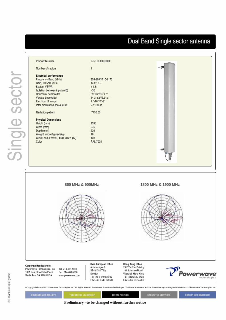
PN
Cle
anS
iteT
riple
Sys
tem
Corporate Headquarters
Powerwave Technologies, Inc. 1801 East St. Andrew Place
Santa Ana, CA 92705 USA
Tel: 714-466-1000
Fax: 714-466-5800 www.powerwave.com
Main European Office
Antennvägen 6
SE-187 80 TäbySweden
Tel: +46 8 540 822 00Fax: +46 8 540 823 40
©Copyright February 2003, Powerwave Technologies, Inc. All Rights reserved. Powerwave, Powerwave Technologies, The Power in Wireless and the Powerwave logo are registered trademarks of Powerwave Technologies, Inc.
Hong Kong Office
23 F Tai Yau Building
181 Johnston RoadWanchai, Hong Kong
Tel: +852 2512 6123Fax: +852 2575 4860
Sin
gle
sect
orDual Band Single sector antenna
Product Number 7750.0C0.0000.00
Number of sectors 1
Electrical performance
Frequency Band (MHz) 824-960/1710-2170
Gain, ±0.5dB (dBi) 14.2/17.5
System VSWR < 1.5:1
Isolation between inputs (dB) >30
Horizontal beamwidth 69°±6°/63°±7°
Vertical beamwidth 14.3°±2°/6.6°±1°
Electrical tilt range 2 °-10°/0°-8°
Inter modulation, 2x+43dBm <-110dBm
Radiation pattern 7750.00
Physical Dimensions
Height (mm) 1390
Width (mm) 275
Depth (mm) 229
Weight, unconfigured (kg) 16Wind Load, Frontal, 150 km/h (N) 428
Color RAL 7035
Preliminary –to be changed without further notice
850 MHz & 900MHz 1800 MHz & 1900 MHz
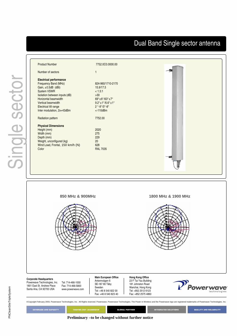
PN
Cle
anS
iteT
riple
Sys
tem
Corporate Headquarters
Powerwave Technologies, Inc. 1801 East St. Andrew Place
Santa Ana, CA 92705 USA
Tel: 714-466-1000
Fax: 714-466-5800 www.powerwave.com
Main European Office
Antennvägen 6
SE-187 80 TäbySweden
Tel: +46 8 540 822 00Fax: +46 8 540 823 40
©Copyright February 2003, Powerwave Technologies, Inc. All Rights reserved. Powerwave, Powerwave Technologies, The Power in Wireless and the Powerwave logo are registered trademarks of Powerwave Technologies, Inc.
Hong Kong Office
23 F Tai Yau Building
181 Johnston RoadWanchai, Hong Kong
Tel: +852 2512 6123Fax: +852 2575 4860
Sin
gle
sect
orDual Band Single sector antenna
Product Number 7752.0C0.0000.00
Number of sectors 1
Electrical performance
Frequency Band (MHz) 824-960/1710-2170
Gain, ±0.5dB (dBi) 15.9/17.5
System VSWR < 1.5:1
Isolation between inputs (dB) >30
Horizontal beamwidth 69°±6°/63°±7°
Vertical beamwidth 9.2°±1°/6.6°±1°
Electrical tilt range 2 °-9°/0°-8°
Inter modulation, 2x+43dBm <-110dBm
Radiation pattern 7752.00
Physical Dimensions
Height (mm) 2020
Width (mm) 275
Depth (mm) 229
Weight, unconfigured (kg) 20Wind Load, Frontal, 150 km/h (N) 628
Color RAL 7035
Preliminary –to be changed without further notice
850 MHz & 900MHz 1800 MHz & 1900 MHz
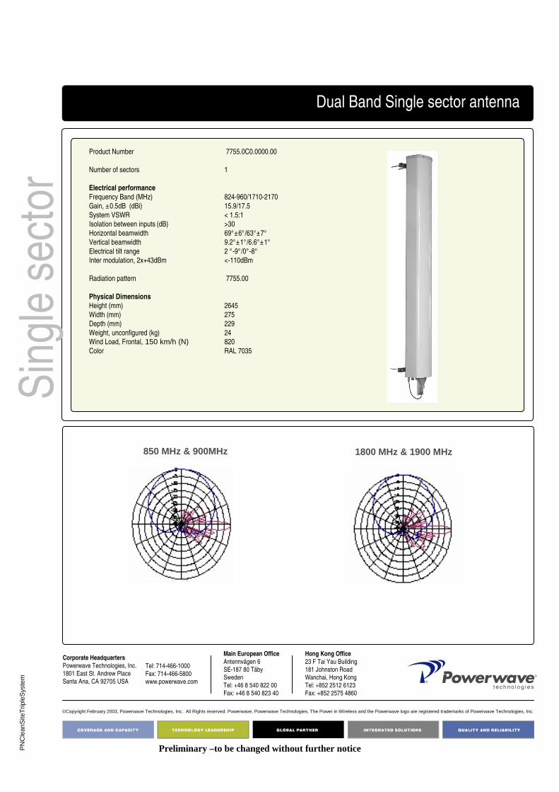
PN
Cle
anS
iteT
riple
Sys
tem
Corporate Headquarters
Powerwave Technologies, Inc. 1801 East St. Andrew Place
Santa Ana, CA 92705 USA
Tel: 714-466-1000
Fax: 714-466-5800 www.powerwave.com
Main European Office
Antennvägen 6
SE-187 80 TäbySweden
Tel: +46 8 540 822 00Fax: +46 8 540 823 40
©Copyright February 2003, Powerwave Technologies, Inc. All Rights reserved. Powerwave, Powerwave Technologies, The Power in Wireless and the Powerwave logo are registered trademarks of Powerwave Technologies, Inc.
Hong Kong Office
23 F Tai Yau Building
181 Johnston RoadWanchai, Hong Kong
Tel: +852 2512 6123Fax: +852 2575 4860
Sin
gle
sect
orDual Band Single sector antenna
Product Number 7755.0C0.0000.00
Number of sectors 1
Electrical performance
Frequency Band (MHz) 824-960/1710-2170
Gain, ±0.5dB (dBi) 15.9/17.5
System VSWR < 1.5:1
Isolation between inputs (dB) >30
Horizontal beamwidth 69°±6°/63°±7°
Vertical beamwidth 9.2°±1°/6.6°±1°
Electrical tilt range 2 °-9°/0°-8°
Inter modulation, 2x+43dBm <-110dBm
Radiation pattern 7755.00
Physical Dimensions
Height (mm) 2645
Width (mm) 275
Depth (mm) 229
Weight, unconfigured (kg) 24Wind Load, Frontal, 150 km/h (N) 820
Color RAL 7035
Preliminary –to be changed without further notice
850 MHz & 900MHz 1800 MHz & 1900 MHz

D03
1-08
279
Rev
A
Pg.
1 o
f 2
Triple Band
Clean SiteTM Triple System Solution
The Powerwave Clean Site Program integrates a full range of multi-band solutions to make the most of tower space. High-volume production in several countries ensures a rapid delivery.
Our products provide design and installation flexibility that answers any needs, such as enabling co-siting of networks and systems, dealing with space and zoning issues limiting the appearance and location of new installations.
Key Benefits:
• Simplified Site Acquisition• Less Visual Impact “Zoning”• Simpler/Faster installation and Commissioning• Simplified Logistics• Improved Quality (products and installation)• Reduced Total Cost• Guaranteed Performance
Clea
n Site
Multi Band SolutionsAntenna / TMA / RET
Simpler LogisticsEasier Installation
lower Noise Figure 0.3 to 0.5 dB less TX loss
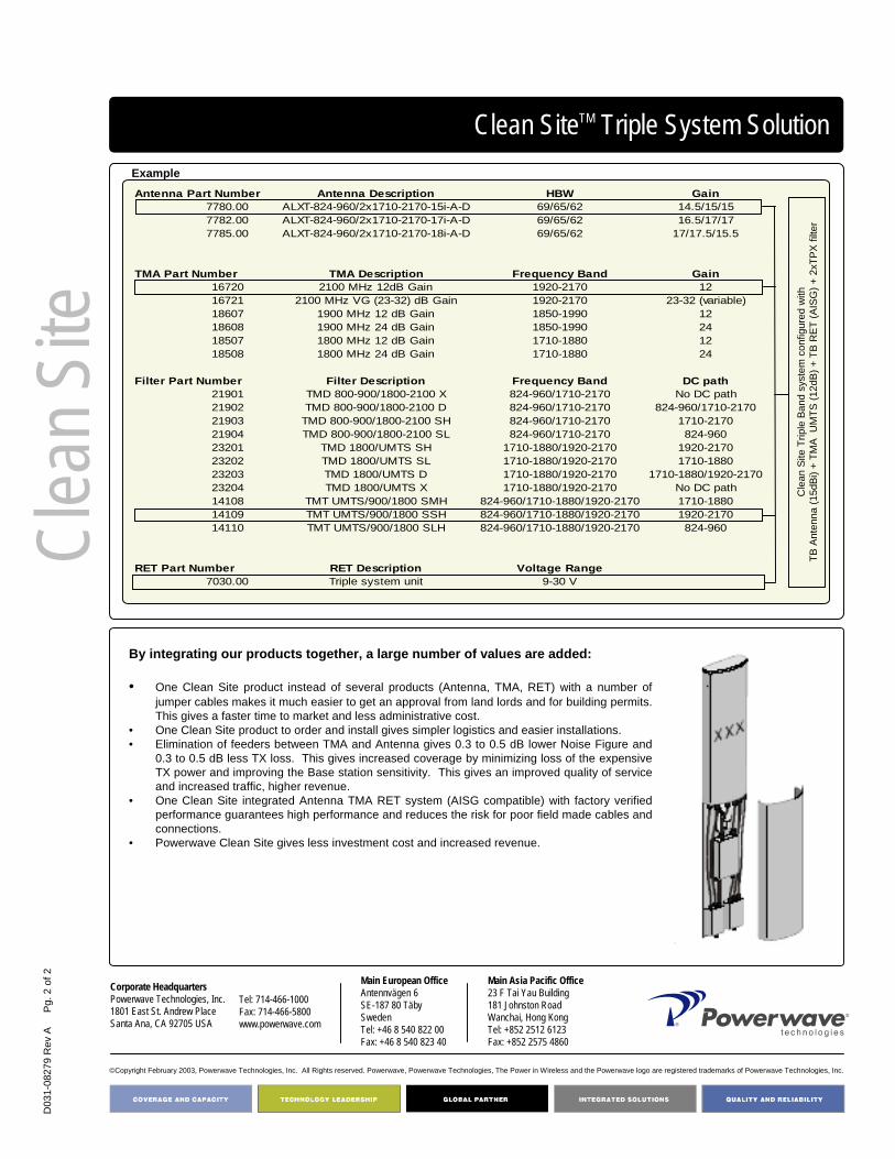
D03
1-08
279
Rev
A
Pg.
2 o
f 2
Corporate HeadquartersPowerwave Technologies, Inc. 1801 East St. Andrew PlaceSanta Ana, CA 92705 USA
Tel: 714-466-1000Fax: 714-466-5800 www.powerwave.com
Main European OfficeAntennvägen 6SE-187 80 TäbySwedenTel: +46 8 540 822 00Fax: +46 8 540 823 40
©Copyright February 2003, Powerwave Technologies, Inc. All Rights reserved. Powerwave, Powerwave Technologies, The Power in Wireless and the Powerwave logo are registered trademarks of Powerwave Technologies, Inc.
Main Asia Pacific Office23 F Tai Yau Building181 Johnston RoadWanchai, Hong KongTel: +852 2512 6123Fax: +852 2575 4860
Antenna Part Number Antenna Description HBW Gain7780.00 ALXT-824-960/2x1710-2170-15i-A-D 69/65/62 14.5/15/157782.00 ALXT-824-960/2x1710-2170-17i-A-D 69/65/62 16.5/17/177785.00 ALXT-824-960/2x1710-2170-18i-A-D 69/65/62 17/17.5/15.5
TMA Part Number TMA Description Frequency Band Gain16720 2100 MHz 12dB Gain 1920-2170 1216721 2100 MHz VG (23-32) dB Gain 1920-2170 23-32 (variable)18607 1900 MHz 12 dB Gain 1850-1990 1218608 1900 MHz 24 dB Gain 1850-1990 2418507 1800 MHz 12 dB Gain 1710-1880 1218508 1800 MHz 24 dB Gain 1710-1880 24
Filter Part Number Filter Description Frequency Band DC path21901 TMD 800-900/1800-2100 X 824-960/1710-2170 No DC path21902 TMD 800-900/1800-2100 D 824-960/1710-2170 824-960/1710-217021903 TMD 800-900/1800-2100 SH 824-960/1710-2170 1710-217021904 TMD 800-900/1800-2100 SL 824-960/1710-2170 824-96023201 TMD 1800/UMTS SH 1710-1880/1920-2170 1920-217023202 TMD 1800/UMTS SL 1710-1880/1920-2170 1710-188023203 TMD 1800/UMTS D 1710-1880/1920-2170 1710-1880/1920-217023204 TMD 1800/UMTS X 1710-1880/1920-2170 No DC path14108 TMT UMTS/900/1800 SMH 824-960/1710-1880/1920-2170 1710-188014109 TMT UMTS/900/1800 SSH 824-960/1710-1880/1920-2170 1920-217014110 TMT UMTS/900/1800 SLH 824-960/1710-1880/1920-2170 824-960
RET Part Number RET Description Voltage Range7030.00 Triple system unit 9-30 V
Clean SiteTM Triple System SolutionExample
By integrating our products together, a large number of values are added:
• One Clean Site product instead of several products (Antenna, TMA, RET) with a number of jumper cables makes it much easier to get an approval from land lords and for building permits. This gives a faster time to market and less administrative cost.
• One Clean Site product to order and install gives simpler logistics and easier installations.• Elimination of feeders between TMA and Antenna gives 0.3 to 0.5 dB lower Noise Figure and
0.3 to 0.5 dB less TX loss. This gives increased coverage by minimizing loss of the expensive TX power and improving the Base station sensitivity. This gives an improved quality of service and increased traffic, higher revenue.
• One Clean Site integrated Antenna TMA RET system (AISG compatible) with factory verified performance guarantees high performance and reduces the risk for poor field made cables and connections.
• Powerwave Clean Site gives less investment cost and increased revenue.
Clea
n Site
Cle
an S
ite T
riple
Ban
d sy
stem
con
figur
ed w
ithTB
Ant
enna
(15d
Bi) +
TM
A U
MTS
(12d
B) +
TB
RE
T (A
ISG
) + 2
xTPX
filte
r
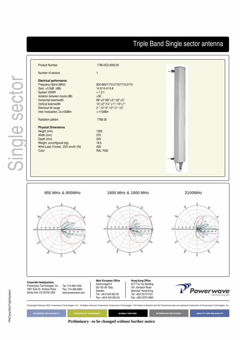
PN
Cle
anS
iteT
riple
Sys
tem
Corporate Headquarters
Powerwave Technologies, Inc. 1801 East St. Andrew Place
Santa Ana, CA 92705 USA
Tel: 714-466-1000
Fax: 714-466-5800 www.powerwave.com
Main European Office
Antennvägen 6
SE-187 80 TäbySweden
Tel: +46 8 540 822 00Fax: +46 8 540 823 40
©Copyright February 2003, Powerwave Technologies, Inc. All Rights reserved. Powerwave, Powerwave Technologies, The Power in Wireless and the Powerwave logo are registered trademarks of Powerwave Technologies, Inc.
Hong Kong Office
23 F Tai Yau Building
181 Johnston RoadWanchai, Hong Kong
Tel: +852 2512 6123Fax: +852 2575 4860
Sin
gle
sect
orTriple Band Single sector antenna
Product Number 7780.0C0.0000.00
Number of sectors 1
Electrical performance
Frequency Band (MHz) 824-960/1710-2170/1710-2170
Gain, ±0.5dB (dBi) 14.5/14.4/14.8
System VSWR < 1.5:1
Isolation between inputs (dB) >30
Horizontal beamwidth 68°±5°/65°±5°/ 62°±5°
Vertical beamwidth 14°±2°/14.°±1°/ 13°±1°
Electrical tilt range 2 °-12°/0°-12°/ 0 °-12°
Inter modulation, 2x+43dBm <-110dBm
Radiation pattern 7780.00
Physical Dimensions
Height (mm) 1390
Width (mm) 275
Depth (mm) 229
Weight, unconfigured (kg) 18,5Wind Load, Frontal, 150 km/h (N) 428
Color RAL 7035
Preliminary –to be changed without further notice
850 MHz & 900MHz 1800 MHz & 1900 MHz 2100MHz

PN
Cle
anS
iteT
riple
Sys
tem
Corporate Headquarters
Powerwave Technologies, Inc. 1801 East St. Andrew Place
Santa Ana, CA 92705 USA
Tel: 714-466-1000
Fax: 714-466-5800 www.powerwave.com
Main European Office
Antennvägen 6
SE-187 80 TäbySweden
Tel: +46 8 540 822 00Fax: +46 8 540 823 40
©Copyright February 2003, Powerwave Technologies, Inc. All Rights reserved. Powerwave, Powerwave Technologies, The Power in Wireless and the Powerwave logo are registered trademarks of Powerwave Technologies, Inc.
Hong Kong Office
23 F Tai Yau Building
181 Johnston RoadWanchai, Hong Kong
Tel: +852 2512 6123Fax: +852 2575 4860
Sin
gle
sect
orTriple Band Single sector antenna
Product Number 7782.0C0.0000.00
Number of sectors 1
Electrical performance
Frequency Band (MHz) 824-960/1710-2170/1710-2170
Gain, ±0.5dB (dBi) 16.5/16.5/16.8
System VSWR < 1.5:1
Isolation between inputs (dB) >30
Horizontal beamwidth 67°/65°/ 64°
Vertical beamwidth 9°±1°/10°±1°/ 9°±1°
Electrical tilt range 2 °-9°/0°-10°/ 0 °-10°
Inter modulation, 2x+43dBm <-110dBm
Radiation pattern 7782.00
Physical Dimensions
Height (mm) 2020
Width (mm) 275
Depth (mm) 229
Weight, unconfigured (kg) 21,5Wind Load, Frontal, 150 km/h (N) 628
Color RAL 7035
Preliminary –to be changed without further notice
850MHz & 900MHz 1800MHz & 1900MHz 2100MHz

PN
Cle
anS
iteT
riple
Sys
tem
Corporate Headquarters
Powerwave Technologies, Inc. 1801 East St. Andrew Place
Santa Ana, CA 92705 USA
Tel: 714-466-1000
Fax: 714-466-5800 www.powerwave.com
Main European Office
Antennvägen 6
SE-187 80 TäbySweden
Tel: +46 8 540 822 00Fax: +46 8 540 823 40
©Copyright February 2003, Powerwave Technologies, Inc. All Rights reserved. Powerwave, Powerwave Technologies, The Power in Wireless and the Powerwave logo are registered trademarks of Powerwave Technologies, Inc.
Hong Kong Office
23 F Tai Yau Building
181 Johnston RoadWanchai, Hong Kong
Tel: +852 2512 6123Fax: +852 2575 4860
Sin
gle
sect
orTriple Band Single sector antenna
Product Number 7785.0C0.0000.00
Number of sectors 1
Electrical performance
Frequency Band (MHz) 824-960/1710-2170/1710-2170
Gain, ±0.5dB (dBi) 17.4/17.2/17.5
System VSWR < 1.5:1
Isolation between inputs (dB) >30
Horizontal beamwidth 65°/65°/ 62°
Vertical beamwidth 7°/7°/6°
Electrical tilt range 2 °-8°/0°-8°/ 0 °-8°
Inter modulation, 2x+43dBm <-110dBm
Radiation pattern 7785.00
Physical Dimensions
Height (mm) 2645
Width (mm) 275
Depth (mm) 229
Weight, unconfigured (kg) 27,5Wind Load, Frontal, 150 km/h (N) 820
Color RAL 7035
Preliminary –to be changed without further notice
850MHz & 900MHz 1800MHz & 1900MHz 2100MHz

MonoPole
Clean SiteTM MonoPole Solution
As a part of Powerwaves CleanSite solutions the MonoPole offers a flexible way
of integrating multi sector solutions in one single radome. MonoPole is the
mounting solution to use when more than one sector is covered from a single
location. The MonoPole solution offers maximum sector coverage with minimum
visual impact.
The Powerwave Clean Site Program integrates a full range of multi-band
solutions to make the most of tower space. High-volume production in several
countries ensures a rapid delivery.
Our products provide design and installation flexibility that answers any needs,
such as enabling co-siting of networks and systems, dealing with space and
zoning issues limiting the appearance and location of new installations.
Key Benefits:
• Multi sector coverage• Simplified Site Acquisition• Less Visual Impact “Zoning”• Simpler/Faster installation and Commissioning• Simplified Logistics• Improved Quality (products and installation)• Reduced Total Cost• Guaranteed Performance
Mon
oPol
e
Multi Band Solutions
Antenna / TMA / RET
Simpler Logistics
Easier InstallationLower Noise Figure
0.3 to 0.5 dB less TX loss
Preliminary –to be changed without further notice

PN
Cle
anS
iteT
riple
Sys
tem
Corporate Headquarters
Powerwave Technologies, Inc. 1801 East St. Andrew Place
Santa Ana, CA 92705 USA
Tel: 714-466-1000
Fax: 714-466-5800 www.powerwave.com
Main European Office
Antennvägen 6
SE-187 80 TäbySweden
Tel: +46 8 540 822 00Fax: +46 8 540 823 40
©Copyright February 2003, Powerwave Technologies, Inc. All Rights reserved. Powerwave, Powerwave Technologies, The Power in Wireless and the Powerwave logo are registered trademarks of Powerwave Technologies, Inc.
Hong Kong Office
23 F Tai Yau Building
181 Johnston RoadWanchai, Hong Kong
Tel: +852 2512 6123Fax: +852 2575 4860
Clean SiteTM MonoPole Solution
By integrating our products together, a large number of values are added:
• One Clean Site product instead of several products (Antenna, TMA, RET) with a number of jumper cables makes it much easier to get an approval from land lords and for building permits. This gives a faster time to market and less administrative cost.
• One Clean Site product to order and install gives simpler logistics and easier installations.• Elimination of feeders between TMA and Antenna gives 0.3 to 0.5 dB lower Noise Figure and
0.3 to 0.5 dB less TX loss. This gives increased coverage by minimizing loss of the expensive TX power and improving the Base station sensitivity. This gives an improved quality of service and increased traffic, higher revenue.
• One Clean Site integrated Antenna TMA RET system (AISG compatible) with factory verified performance guarantees high performance and reduces the risk for poor field made cables and connections.
• Powerwave Clean Site gives less investment cost and increased revenue.
Mon
oPol
e
Preliminary –to be changed without further notice
Antenna system numbering Q Description
0 Standard tilt range1-9 Shifted tilt variants
PPPP.QRS.TUVX.YZR S Description
Basic config Integration config 1 Monopole 1 sectorM 2 Monopole 2 sector
3 Monopole 3 sectorPPPP part number antenna 1 Intellimast 1 sector
Q Tilt variant I 2 Intellimast 2 sectorRS Concept 3 Intellimast 3 sector
0 Standard antenna No bracketT RET Functionality F Standard antenna Fixed bracketU RET SW U Standard antenna Connector upV # of TMAs per sector S C Standard antenna Combined F&UX # of combined filter bands per sector T Standard antenna Tilt bracket
YZ Variant # D Standard antenna Combined T&UC 0 Single sector Clean Site
T Description U Description0 No RET 0 No RET1 1 RET controlled band 1 AISG SW2 2 RET controlled bands 2 Ericsson3 3 RET controlled bands 3 SiemensA i-RET (male connector) 4 3GPPB i-RET (male+female connector) 5 AISG/EricssonC i-RET (male+male) 6 AISG/Siemens
V Description X Description0 No TMA 0 No Filters1 1 TMA per sector 2 2 diplexers per sector2 2 TMA per sector 3 2 triplexers per sectorE Empty TMA box incl E Empty Filter box incl

PN
Cle
anS
iteT
riple
Sys
tem
Corporate HeadquartersPowerwave Technologies, Inc. 1801 East St. Andrew Place
Santa Ana, CA 92705 USA
Tel: 714-466-1000
Fax: 714-466-5800 www.powerwave.com
Main European OfficeAntennvägen 6
SE-187 80 TäbySweden
Tel: +46 8 540 822 00Fax: +46 8 540 823 40
©Copyright February 2003, Powerwave Technologies, Inc. All Rights reserved. Powerwave, Powerwave Technologies, The Power in Wireless and the Powerwave logo are registered trademarks of Powerwave Technologies, Inc.
Hong Kong Office23 F Tai Yau Building
181 Johnston RoadWanchai, Hong Kong
Tel: +852 2512 6123Fax: +852 2575 4860
Mon
oPol
eTrisector 1800/UMTS Single Broad Band MonoPole antenna
Product Number 7721.0M3.0000.00
Number of sectors 3
Azimuth variation +/-15 degrees
Electrical performance
Frequency Band (MHz) 1710-2170
Gain, ±0.5dB (dBi) 18
System VSWR < 1.5:1
Isolation between inputs (dB) >30
Horizontal beamwidth 65°±5°
Vertical beamwidth 6.6°±0.6°
Electrical tilt range 0°-8°
Inter modulation, 2x+43dBm <-110dBm
Radiation pattern 7721.00
Physical Dimensions
Height (mm) 2215
Diameter (mm) 340
Weight (kg) 53
Wind load @ 40m/s (N) 1200 @ 60 feet
Color RAL 7035
For additional antenna data, check the 7721.00 data sheet
Space for TMAs included in design
Preliminary –to be changed without further notice
Accessories for Monopole Ø340ACS50 BaseACS51 PlatformACS04 Cable inletACS05 Roof adapterACS52 1m ExtensionACS54 Hinge kitACS55 Lightning poleACS56 Cable kit ACS57 TMA installation bracket
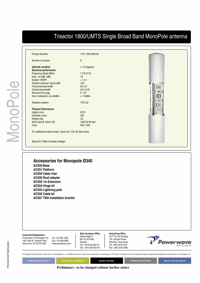
PN
Cle
anS
iteT
riple
Sys
tem
Corporate HeadquartersPowerwave Technologies, Inc. 1801 East St. Andrew Place
Santa Ana, CA 92705 USA
Tel: 714-466-1000
Fax: 714-466-5800 www.powerwave.com
Main European OfficeAntennvägen 6
SE-187 80 TäbySweden
Tel: +46 8 540 822 00Fax: +46 8 540 823 40
©Copyright February 2003, Powerwave Technologies, Inc. All Rights reserved. Powerwave, Powerwave Technologies, The Power in Wireless and the Powerwave logo are registered trademarks of Powerwave Technologies, Inc.
Hong Kong Office23 F Tai Yau Building
181 Johnston RoadWanchai, Hong Kong
Tel: +852 2512 6123Fax: +852 2575 4860
Mon
oPol
eTrisector 1800/UMTS Single Broad Band MonoPole antenna
Product Number 7721.1M3.0000.00
Number of sectors 3
Azimuth variation +/-15 degrees
Electrical performance
Frequency Band (MHz) 1710-2170
Gain, ±0.5dB (dBi) 18
System VSWR < 1.5:1
Isolation between inputs (dB) >30
Horizontal beamwidth 65°±5°
Vertical beamwidth 6.6°±0.6°
Electrical tilt range 2°-10°
Inter modulation, 2x+43dBm <-110dBm
Radiation pattern 7721.02
Physical Dimensions
Height (mm) 2215
Diameter (mm) 340
Weight (kg) 53
Wind load @ 40m/s (N) 1200 @ 60 feet
Color RAL 7035
For additional antenna data, check the 7721.02 data sheet
Space for TMAs included indesign
Preliminary –to be changed without further notice
Accessories for Monopole Ø340ACS50 BaseACS51 PlatformACS04 Cable inletACS05 Roof adapterACS52 1m ExtensionACS54 Hinge kitACS55 Lightning poleACS56 Cable kit ACS57 TMA installation bracket

PN
Cle
anS
iteT
riple
Sys
tem
Corporate HeadquartersPowerwave Technologies, Inc. 1801 East St. Andrew Place
Santa Ana, CA 92705 USA
Tel: 714-466-1000
Fax: 714-466-5800 www.powerwave.com
Main European OfficeAntennvägen 6
SE-187 80 TäbySweden
Tel: +46 8 540 822 00Fax: +46 8 540 823 40
©Copyright February 2003, Powerwave Technologies, Inc. All Rights reserved. Powerwave, Powerwave Technologies, The Power in Wireless and the Powerwave logo are registered trademarks of Powerwave Technologies, Inc.
Hong Kong Office23 F Tai Yau Building
181 Johnston RoadWanchai, Hong Kong
Tel: +852 2512 6123Fax: +852 2575 4860
Mon
oPol
eTrisector 1800/UMTS Single Broad Band MonoPole antenna
Product Number 7721.3M3.0000.00
Number of sectors 3
Azimuth variation +/-15 degrees
Electrical performance
Frequency Band (MHz) 1710-2170
Gain, ±0.5dB (dBi) 18
System VSWR < 1.5:1
Isolation between inputs (dB) >30
Horizontal beamwidth 65°±5°
Vertical beamwidth 6.6°±0.6°
Electrical tilt range 6°-14°
Inter modulation, 2x+43dBm <-110dBm
Radiation pattern 7721.06
Physical Dimensions
Height (mm) 2215
Diameter (mm) 340
Weight (kg) 53
Wind load @ 40m/s (N) 1200 @ 60 feet
Color RAL 7035
For additional antenna data, please check the 7721.06 data sheet
Space for TMAs included in design
Preliminary –to be changed without further notice
Accessories for Monopole Ø340ACS50 BaseACS51 PlatformACS04 Cable inletACS05 Roof adapterACS52 1m ExtensionACS54 Hinge kitACS55 Lightning poleACS56 Cable kit ACS57 TMA installation bracket

PN
Cle
anS
iteT
riple
Sys
tem
Corporate Headquarters
Powerwave Technologies, Inc. 1801 East St. Andrew Place
Santa Ana, CA 92705 USA
Tel: 714-466-1000
Fax: 714-466-5800 www.powerwave.com
Main European Office
Antennvägen 6
SE-187 80 TäbySweden
Tel: +46 8 540 822 00Fax: +46 8 540 823 40
©Copyright February 2003, Powerwave Technologies, Inc. All Rights reserved. Powerwave, Powerwave Technologies, The Power in Wireless and the Powerwave logo are registered trademarks of Powerwave Technologies, Inc.
Hong Kong Office
23 F Tai Yau Building
181 Johnston RoadWanchai, Hong Kong
Tel: +852 2512 6123Fax: +852 2575 4860
Mon
oPol
e
Product Number 77500.0M3.0000.00
Number of sectors 3
Azimuth variation +/-15 degrees in 5deg steps
Electrical performance
Frequency Band (MHz) 824-960/1710-2170
Gain, ±0.5dB (dBi) 14.2/17.5
System VSWR < 1.5:1
Isolation between inputs (dB) >30
Horizontal beamwidth 69°±6°/63°±7°
Vertical beamwidth 14.3°±2°/6.6°±1°
Electrical tilt range 2 °-10°/0°-8°
Inter modulation, 2x+43dBm <-110dBm
Radiation pattern 7750.00
Physical Dimensions
Height (mm) 1850
Diameter (mm) 500
Weight (kg) 100
Wind load @ 40m/s (N) 1130 @ 60 feet
Color RAL 7035
AccessoriesExtension tube, 2m ACS01Wire sustaining ring ACS02TMA/Filter mounting tube, 0.5m ACS03Cable inlet ACS04Roof adapter ACS05Lightning Pole ACS06Door kit, Antenna ACS07.1Door kit, 1 box ACS07.2Door kit, 1 box+antenna ACS07.3Door kit, 2 boxes+antenna ACS07.4Cable kit, dual band ACS10Cable kit, triple band ACS11Cable kit, Ant-TMA ACS12Cable fixation plate ACS20
Interface drawing: antenna_interface.dxfwww.powerwave.com
Preliminary –to be changed without further notice
Trisector 900/UMTS Dual Broad Band MonoPole
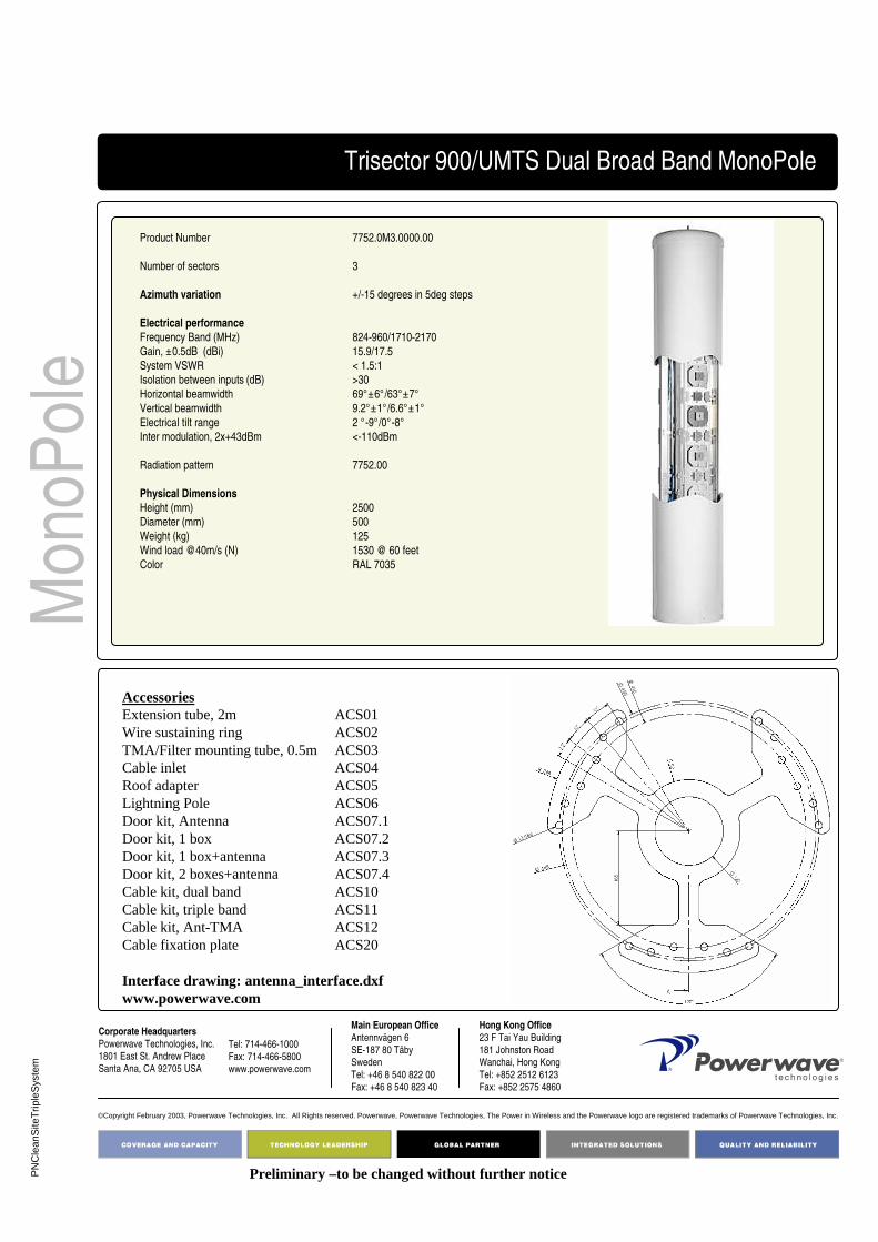
PN
Cle
anS
iteT
riple
Sys
tem
Corporate Headquarters
Powerwave Technologies, Inc. 1801 East St. Andrew Place
Santa Ana, CA 92705 USA
Tel: 714-466-1000
Fax: 714-466-5800 www.powerwave.com
Main European Office
Antennvägen 6
SE-187 80 TäbySweden
Tel: +46 8 540 822 00Fax: +46 8 540 823 40
©Copyright February 2003, Powerwave Technologies, Inc. All Rights reserved. Powerwave, Powerwave Technologies, The Power in Wireless and the Powerwave logo are registered trademarks of Powerwave Technologies, Inc.
Hong Kong Office
23 F Tai Yau Building
181 Johnston RoadWanchai, Hong Kong
Tel: +852 2512 6123Fax: +852 2575 4860
Mon
oPol
e
Product Number 7752.0M3.0000.00
Number of sectors 3
Azimuth variation +/-15 degrees in 5deg steps
Electrical performance
Frequency Band (MHz) 824-960/1710-2170
Gain, ±0.5dB (dBi) 15.9/17.5
System VSWR < 1.5:1
Isolation between inputs (dB) >30
Horizontal beamwidth 69°±6°/63°±7°
Vertical beamwidth 9.2°±1°/6.6°±1°
Electrical tilt range 2 °-9°/0°-8°
Inter modulation, 2x+43dBm <-110dBm
Radiation pattern 7752.00
Physical Dimensions
Height (mm) 2500
Diameter (mm) 500
Weight (kg) 125
Wind load @40m/s (N) 1530 @ 60 feet
Color RAL 7035
AccessoriesExtension tube, 2m ACS01Wire sustaining ring ACS02TMA/Filter mounting tube, 0.5m ACS03Cable inlet ACS04Roof adapter ACS05Lightning Pole ACS06Door kit, Antenna ACS07.1Door kit, 1 box ACS07.2Door kit, 1 box+antenna ACS07.3Door kit, 2 boxes+antenna ACS07.4Cable kit, dual band ACS10Cable kit, triple band ACS11Cable kit, Ant-TMA ACS12Cable fixation plate ACS20
Interface drawing: antenna_interface.dxfwww.powerwave.com
Preliminary –to be changed without further notice
Trisector 900/UMTS Dual Broad Band MonoPole

PN
Cle
anS
iteT
riple
Sys
tem
Corporate Headquarters
Powerwave Technologies, Inc. 1801 East St. Andrew Place
Santa Ana, CA 92705 USA
Tel: 714-466-1000
Fax: 714-466-5800 www.powerwave.com
Main European Office
Antennvägen 6
SE-187 80 TäbySweden
Tel: +46 8 540 822 00Fax: +46 8 540 823 40
©Copyright February 2003, Powerwave Technologies, Inc. All Rights reserved. Powerwave, Powerwave Technologies, The Power in Wireless and the Powerwave logo are registered trademarks of Powerwave Technologies, Inc.
Hong Kong Office
23 F Tai Yau Building
181 Johnston RoadWanchai, Hong Kong
Tel: +852 2512 6123Fax: +852 2575 4860
Mon
oPol
e
Product Number 7755.0M3.0000.00
Number of sectors 3
Azimuth variation +/-15 degrees in 5deg steps
Electrical performance
Frequency Band (MHz) 824-960/1710-2170
Gain, ±0.5dB (dBi) 15.9/17.5
System VSWR < 1.5:1
Isolation between inputs (dB) >30
Horizontal beamwidth 69°±6°/63°±7°
Vertical beamwidth 9.2°±1°/6.6°±1°
Electrical tilt range 2 °-9°/0°-8°
Inter modulation, 2x+43dBm <-110dBm
Radiation pattern 7755.00
Physical Dimensions
Height (mm) 3100
Diameter (mm) 500
Weight (kg) 150
Wind load @40m/s /(N) 1900 @ 60 feet
Color RAL 7035
AccessoriesExtension tube, 2m ACS01Wire sustaining ring ACS02TMA/Filter mounting tube, 0.5m ACS03Cable inlet ACS04Roof adapter ACS05Lightning Pole ACS06Door kit, Antenna ACS07.1Door kit, 1 box ACS07.2Door kit, 1 box+antenna ACS07.3Door kit, 2 boxes+antenna ACS07.4Cable kit, dual band ACS10Cable kit, triple band ACS11Cable kit, Ant-TMA ACS12Cable fixation plate ACS20
Interface drawing: antenna_interface.dxfwww.powerwave.com
Preliminary –to be changed without further notice
Trisector 900/UMTS Dual Broad Band MonoPole

PN
Cle
anS
iteT
riple
Sys
tem
Corporate Headquarters
Powerwave Technologies, Inc. 1801 East St. Andrew Place
Santa Ana, CA 92705 USA
Tel: 714-466-1000
Fax: 714-466-5800 www.powerwave.com
Main European Office
Antennvägen 6
SE-187 80 TäbySweden
Tel: +46 8 540 822 00Fax: +46 8 540 823 40
©Copyright February 2003, Powerwave Technologies, Inc. All Rights reserved. Powerwave, Powerwave Technologies, The Power in Wireless and the Powerwave logo are registered trademarks of Powerwave Technologies, Inc.
Hong Kong Office
23 F Tai Yau Building
181 Johnston RoadWanchai, Hong Kong
Tel: +852 2512 6123Fax: +852 2575 4860
Mon
oPol
e
Product Number 7780.0M3.0000.00
Number of sectors 3
Azimuth variation +/-15 degrees in 5deg steps
Electrical performance
Frequency Band (MHz) 824-960/1710-2170/1710-2170
Gain, ±0.5dB (dBi) 14.5/14.4/14.8
System VSWR < 1.5:1
Isolation between inputs (dB) >30
Horizontal beamwidth 68°±5°/65°±5°/ 62°±5°
Vertical beamwidth 14°±2°/14.°±1°/ 13°±1°
Electrical tilt range 2 °-12°/0°-12°/ 0 °-12°
Inter modulation, 2x+43dBm <-110dBm
Radiation pattern 7780.00
Physical Dimensions
Height (mm) 1850
Diameter (mm) 500
Weight (kg) 105
Wind load @40m/s (N) 1130 @ 60 feet
Color RAL 7035
Preliminary –to be changed without further notice
AccessoriesExtension tube, 2m ACS01Wire sustaining ring ACS02TMA/Filter mounting tube, 0.5m ACS03Cable inlet ACS04Roof adapter ACS05Lightning Pole ACS06Door kit, Antenna ACS07.1Door kit, 1 box ACS07.2Door kit, 1 box+antenna ACS07.3Door kit, 2 boxes+antenna ACS07.4Cable kit, dual band ACS10Cable kit, triple band ACS11Cable kit, Ant-TMA ACS12Cable fixation plate ACS20
Interface drawing: antenna_interface.dxfwww.powerwave.com
Trisector 900/1800/UMTS Triple Broad Band MonoPole

PN
Cle
anS
iteT
riple
Sys
tem
Corporate Headquarters
Powerwave Technologies, Inc. 1801 East St. Andrew Place
Santa Ana, CA 92705 USA
Tel: 714-466-1000
Fax: 714-466-5800 www.powerwave.com
Main European Office
Antennvägen 6
SE-187 80 TäbySweden
Tel: +46 8 540 822 00Fax: +46 8 540 823 40
©Copyright February 2003, Powerwave Technologies, Inc. All Rights reserved. Powerwave, Powerwave Technologies, The Power in Wireless and the Powerwave logo are registered trademarks of Powerwave Technologies, Inc.
Hong Kong Office
23 F Tai Yau Building
181 Johnston RoadWanchai, Hong Kong
Tel: +852 2512 6123Fax: +852 2575 4860
Mon
oPol
e
Product Number 7782.0M3.0000.00
Number of sectors 3
Azimuth variation +/-15 degrees in 5deg steps
Electrical performance
Frequency Band (MHz) 824-960/1710-2170/1710-2170
Gain, ±0.5dB (dBi) 16.5/16.5/16.8
System VSWR < 1.5:1
Isolation between inputs (dB) >30
Horizontal beamwidth 67°/65°/ 64°
Vertical beamwidth 9°±1°/10°±1°/ 9°±1°
Electrical tilt range 2 °-9°/0°-10°/ 0 °-10°
Inter modulation, 2x+43dBm <-110dBm
Radiation pattern 7782.00
Physical Dimensions
Height (mm) 2500
Diameter (mm) 500
Weight (kg) 130
Wind load @40m/s (N) 1530 @ 60 feet
Color RAL 7035
Preliminary –to be changed without further notice
AccessoriesExtension tube, 2m ACS01Wire sustaining ring ACS02TMA/Filter mounting tube, 0.5m ACS03Cable inlet ACS04Roof adapter ACS05Lightning Pole ACS06Door kit, Antenna ACS07.1Door kit, 1 box ACS07.2Door kit, 1 box+antenna ACS07.3Door kit, 2 boxes+antenna ACS07.4Cable kit, dual band ACS10Cable kit, triple band ACS11Cable kit, Ant-TMA ACS12Cable fixation plate ACS20
Interface drawing: antenna_interface.dxfwww.powerwave.com
Trisector 900/1800/UMTS Triple Broad Band MonoPole

PN
Cle
anS
iteT
riple
Sys
tem
Corporate Headquarters
Powerwave Technologies, Inc. 1801 East St. Andrew Place
Santa Ana, CA 92705 USA
Tel: 714-466-1000
Fax: 714-466-5800 www.powerwave.com
Main European Office
Antennvägen 6
SE-187 80 TäbySweden
Tel: +46 8 540 822 00Fax: +46 8 540 823 40
©Copyright February 2003, Powerwave Technologies, Inc. All Rights reserved. Powerwave, Powerwave Technologies, The Power in Wireless and the Powerwave logo are registered trademarks of Powerwave Technologies, Inc.
Hong Kong Office
23 F Tai Yau Building
181 Johnston RoadWanchai, Hong Kong
Tel: +852 2512 6123Fax: +852 2575 4860
Mon
oPol
e
Product Number 7785.0M3.0000.00
Number of sectors 3
Azimuth variation +/-15 degrees in 5deg steps
Electrical performance
Frequency Band (MHz) 824-960/1710-2170/1710-2170
Gain, ±0.5dB (dBi) 17.4/17.2/17.5
System VSWR < 1.5:1
Isolation between inputs (dB) >30
Horizontal beamwidth 65°/65°/ 62°
Vertical beamwidth 7°/7°/6°
Electrical tilt range 2 °-8°/0°-8°/ 0 °-8°
Inter modulation, 2x+43dBm <-110dBm
Radiation pattern 7785.00
Physical Dimensions
Height (mm) 3100
Diameter (mm) 500
Weight (kg) 155
Wind load @40m/s (N) 1900 @ 60 feet
Color RAL 7035
Preliminary –to be changed without further notice
AccessoriesExtension tube, 2m ACS01Wire sustaining ring ACS02TMA/Filter mounting tube, 0.5m ACS03Cable inlet ACS04Roof adapter ACS05Lightning Pole ACS06Door kit, Antenna ACS07.1Door kit, 1 box ACS07.2Door kit, 1 box+antenna ACS07.3Door kit, 2 boxes+antenna ACS07.4Cable kit, dual band ACS10Cable kit, triple band ACS11Cable kit, Ant-TMA ACS12Cable fixation plate ACS20
Interface drawing: antenna_interface.dxfwww.powerwave.com
Trisector 900/1800/UMTS Triple Broad Band MonoPole
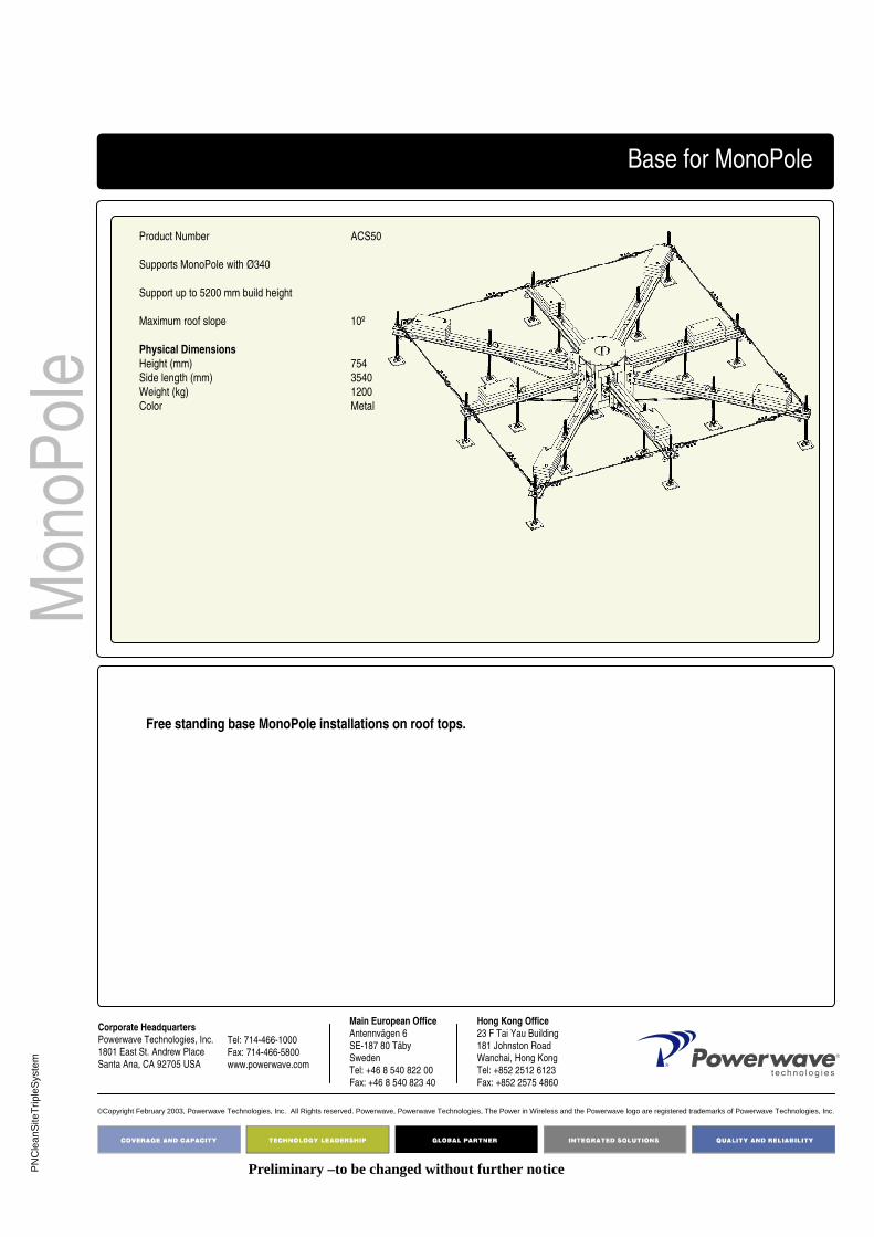
PN
Cle
anS
iteT
riple
Sys
tem
Corporate HeadquartersPowerwave Technologies, Inc. 1801 East St. Andrew Place
Santa Ana, CA 92705 USA
Tel: 714-466-1000
Fax: 714-466-5800 www.powerwave.com
Main European OfficeAntennvägen 6
SE-187 80 TäbySweden
Tel: +46 8 540 822 00Fax: +46 8 540 823 40
©Copyright February 2003, Powerwave Technologies, Inc. All Rights reserved. Powerwave, Powerwave Technologies, The Power in Wireless and the Powerwave logo are registered trademarks of Powerwave Technologies, Inc.
Hong Kong Office23 F Tai Yau Building
181 Johnston RoadWanchai, Hong Kong
Tel: +852 2512 6123Fax: +852 2575 4860
Mon
oPol
eBase for MonoPole
Product Number ACS50
Supports MonoPole with Ø340
Support up to 5200 mm build height
Maximum roof slope 10º
Physical Dimensions
Height (mm) 754
Side length (mm) 3540
Weight (kg) 1200
Color Metal
Preliminary –to be changed without further notice
Free standing base MonoPole installations on roof tops.

PN
Cle
anS
iteT
riple
Sys
tem
Corporate HeadquartersPowerwave Technologies, Inc. 1801 East St. Andrew Place
Santa Ana, CA 92705 USA
Tel: 714-466-1000
Fax: 714-466-5800 www.powerwave.com
Main European OfficeAntennvägen 6
SE-187 80 TäbySweden
Tel: +46 8 540 822 00Fax: +46 8 540 823 40
©Copyright February 2003, Powerwave Technologies, Inc. All Rights reserved. Powerwave, Powerwave Technologies, The Power in Wireless and the Powerwave logo are registered trademarks of Powerwave Technologies, Inc.
Hong Kong Office23 F Tai Yau Building
181 Johnston RoadWanchai, Hong Kong
Tel: +852 2512 6123Fax: +852 2575 4860
Mon
oPol
ePlatform for MonoPole
Product Number ACS51
Supports MonoPole with Ø340
Support up to 4000m total height
Physical Dimensions
Height (mm)
Side length (mm) 2500
Weight (kg)
Color Metal
Preliminary –to be changed without further notice
.

PN
Cle
anS
iteT
riple
Sys
tem
Corporate HeadquartersPowerwave Technologies, Inc. 1801 East St. Andrew Place
Santa Ana, CA 92705 USA
Tel: 714-466-1000
Fax: 714-466-5800 www.powerwave.com
Main European OfficeAntennvägen 6
SE-187 80 TäbySweden
Tel: +46 8 540 822 00Fax: +46 8 540 823 40
©Copyright February 2003, Powerwave Technologies, Inc. All Rights reserved. Powerwave, Powerwave Technologies, The Power in Wireless and the Powerwave logo are registered trademarks of Powerwave Technologies, Inc.
Hong Kong Office23 F Tai Yau Building
181 Johnston RoadWanchai, Hong Kong
Tel: +852 2512 6123Fax: +852 2575 4860
Mon
oPol
eCable inlet
Product Number ACS04
Supports MonoPole with Ø340 and Ø500
Physical Dimensions
Height (mm) 190
Diameter (mm) 496
Weight (kg) 23
Color Metal
Preliminary –to be changed without further notice

PN
Cle
anS
iteT
riple
Sys
tem
Corporate HeadquartersPowerwave Technologies, Inc. 1801 East St. Andrew Place
Santa Ana, CA 92705 USA
Tel: 714-466-1000
Fax: 714-466-5800 www.powerwave.com
Main European OfficeAntennvägen 6
SE-187 80 TäbySweden
Tel: +46 8 540 822 00Fax: +46 8 540 823 40
©Copyright February 2003, Powerwave Technologies, Inc. All Rights reserved. Powerwave, Powerwave Technologies, The Power in Wireless and the Powerwave logo are registered trademarks of Powerwave Technologies, Inc.
Hong Kong Office23 F Tai Yau Building
181 Johnston RoadWanchai, Hong Kong
Tel: +852 2512 6123Fax: +852 2575 4860
Mon
oPol
eRoof Adapter
Product Number ACS05
Physical Dimensions
Height (mm) 170
Diameter (mm) 550
Weight (kg) 37
Color Metal
Preliminary –to be changed without further notice
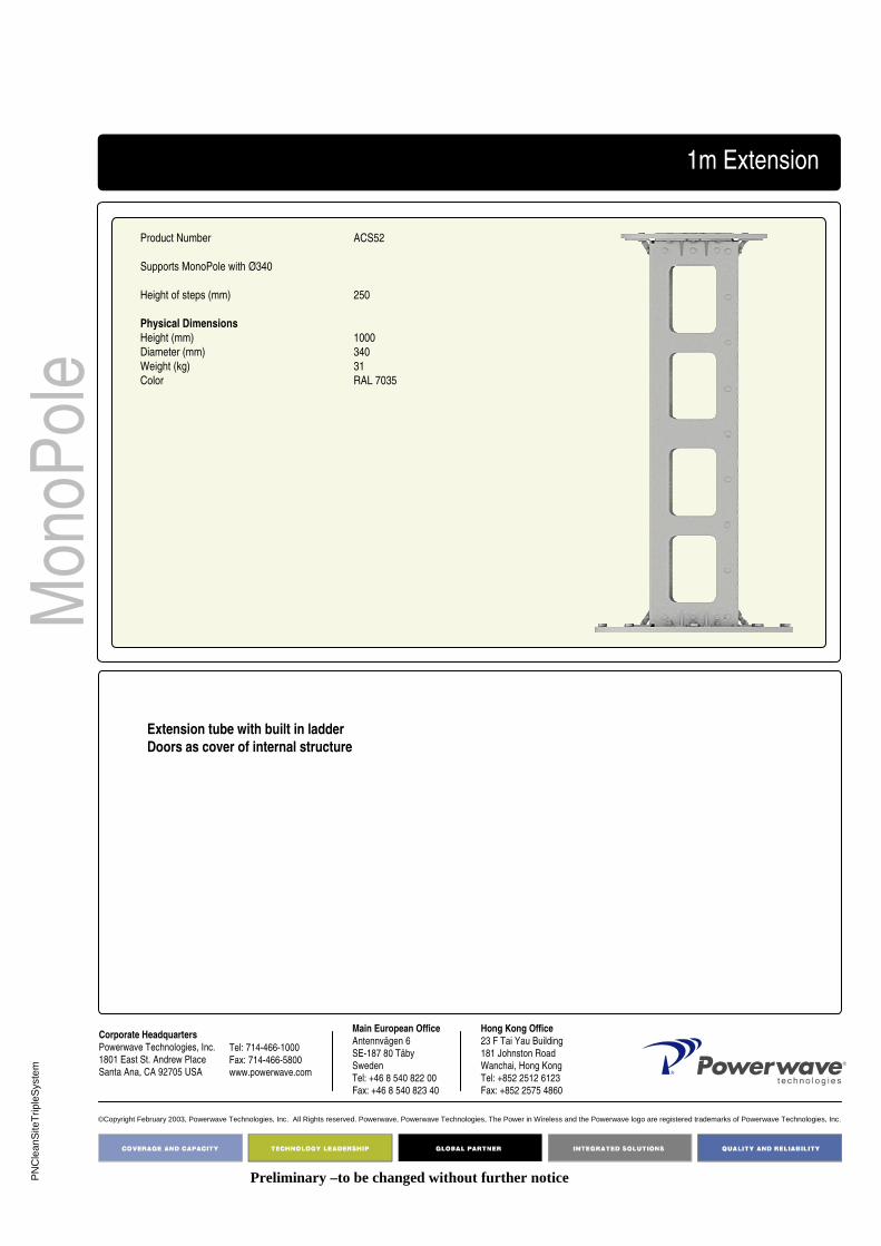
PN
Cle
anS
iteT
riple
Sys
tem
Corporate HeadquartersPowerwave Technologies, Inc. 1801 East St. Andrew Place
Santa Ana, CA 92705 USA
Tel: 714-466-1000
Fax: 714-466-5800 www.powerwave.com
Main European OfficeAntennvägen 6
SE-187 80 TäbySweden
Tel: +46 8 540 822 00Fax: +46 8 540 823 40
©Copyright February 2003, Powerwave Technologies, Inc. All Rights reserved. Powerwave, Powerwave Technologies, The Power in Wireless and the Powerwave logo are registered trademarks of Powerwave Technologies, Inc.
Hong Kong Office23 F Tai Yau Building
181 Johnston RoadWanchai, Hong Kong
Tel: +852 2512 6123Fax: +852 2575 4860
Mon
oPol
e1m Extension
Product Number ACS52
Supports MonoPole with Ø340
Height of steps (mm) 250
Physical Dimensions
Height (mm) 1000
Diameter (mm) 340
Weight (kg) 31
Color RAL 7035
Preliminary –to be changed without further notice
Extension tube with built in ladderDoors as cover of internal structure

PN
Cle
anS
iteT
riple
Sys
tem
Corporate HeadquartersPowerwave Technologies, Inc. 1801 East St. Andrew Place
Santa Ana, CA 92705 USA
Tel: 714-466-1000
Fax: 714-466-5800 www.powerwave.com
Main European OfficeAntennvägen 6
SE-187 80 TäbySweden
Tel: +46 8 540 822 00Fax: +46 8 540 823 40
©Copyright February 2003, Powerwave Technologies, Inc. All Rights reserved. Powerwave, Powerwave Technologies, The Power in Wireless and the Powerwave logo are registered trademarks of Powerwave Technologies, Inc.
Hong Kong Office23 F Tai Yau Building
181 Johnston RoadWanchai, Hong Kong
Tel: +852 2512 6123Fax: +852 2575 4860
Mon
oPol
eHinge kit
Product Number ACS54
Supports MonoPole with Ø340
Physical Dimensions
Weight (kg)
Color RAL 7035
Preliminary –to be changed without further notice
Removable hinge kit for MonoPole installations.Can be used during installation for simplified raise of MonoPole.
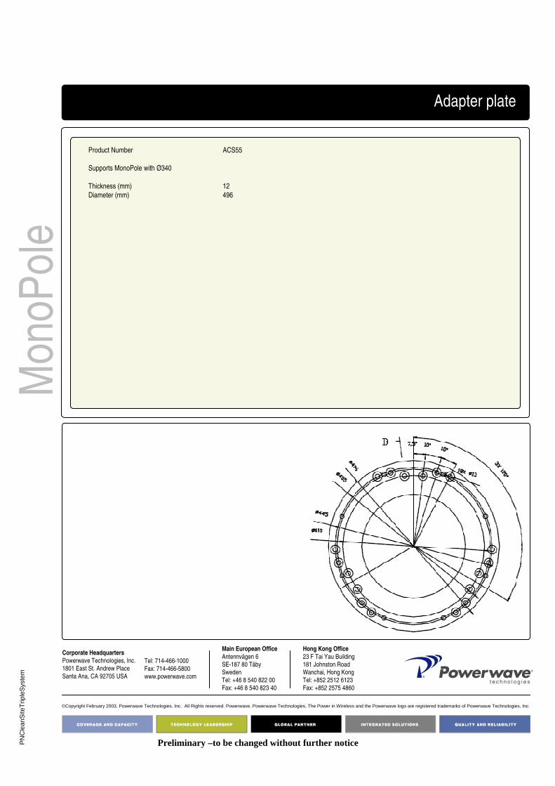
PN
Cle
anS
iteT
riple
Sys
tem
Corporate HeadquartersPowerwave Technologies, Inc. 1801 East St. Andrew Place
Santa Ana, CA 92705 USA
Tel: 714-466-1000
Fax: 714-466-5800 www.powerwave.com
Main European OfficeAntennvägen 6
SE-187 80 TäbySweden
Tel: +46 8 540 822 00Fax: +46 8 540 823 40
©Copyright February 2003, Powerwave Technologies, Inc. All Rights reserved. Powerwave, Powerwave Technologies, The Power in Wireless and the Powerwave logo are registered trademarks of Powerwave Technologies, Inc.
Hong Kong Office23 F Tai Yau Building
181 Johnston RoadWanchai, Hong Kong
Tel: +852 2512 6123Fax: +852 2575 4860
Mon
oPol
eAdapter plate
Product Number ACS55
Supports MonoPole with Ø340
Thickness (mm) 12
Diameter (mm) 496
Preliminary –to be changed without further notice

PN
Cle
anS
iteT
riple
Sys
tem
Corporate HeadquartersPowerwave Technologies, Inc. 1801 East St. Andrew Place
Santa Ana, CA 92705 USA
Tel: 714-466-1000
Fax: 714-466-5800 www.powerwave.com
Main European OfficeAntennvägen 6
SE-187 80 TäbySweden
Tel: +46 8 540 822 00Fax: +46 8 540 823 40
©Copyright February 2003, Powerwave Technologies, Inc. All Rights reserved. Powerwave, Powerwave Technologies, The Power in Wireless and the Powerwave logo are registered trademarks of Powerwave Technologies, Inc.
Hong Kong Office23 F Tai Yau Building
181 Johnston RoadWanchai, Hong Kong
Tel: +852 2512 6123Fax: +852 2575 4860
Mon
oPol
eCable kit
Product Number ACS56
Supports MonoPole with Ø340
No. of cables 6
Cable type ½”
Length (mm)
Cable kit interconnect between Antennas and TMAs
Preliminary –to be changed without further notice

PN
Cle
anS
iteT
riple
Sys
tem
Corporate HeadquartersPowerwave Technologies, Inc. 1801 East St. Andrew Place
Santa Ana, CA 92705 USA
Tel: 714-466-1000
Fax: 714-466-5800 www.powerwave.com
Main European OfficeAntennvägen 6
SE-187 80 TäbySweden
Tel: +46 8 540 822 00Fax: +46 8 540 823 40
©Copyright February 2003, Powerwave Technologies, Inc. All Rights reserved. Powerwave, Powerwave Technologies, The Power in Wireless and the Powerwave logo are registered trademarks of Powerwave Technologies, Inc.
Hong Kong Office23 F Tai Yau Building
181 Johnston RoadWanchai, Hong Kong
Tel: +852 2512 6123Fax: +852 2575 4860
Mon
oPol
eTMA installation bracket kit
Product Number ACS57
Supports MonoPole with Ø340
No. of brackets 3
Weight (kg)
Width (mm) 145
Height (mm) 410
Width (mm) 2
Mounting hard ware for TMAs included
Preliminary –to be changed without further notice

D03
1-08
419
Rev
. A
Pg.
1 of
2
Part Number:7456.00A
Antenna length: < 1.5 meter/5 feet
4168.11.33.00 Antenna BracketsTilt Bracket Kit
Weight:3.6 kg/7.9 lbs
All Powerwave antennas shorter than 1.5 meter (5 feet)* shall be installed with Powerwave tilt bracket, 7456.00. Below is a list outlining which antennas come with pre-mounted tilt brackets. For a reference list of accessory products see mechanical specification on page 2.
*Urban antennas longer than 1.5 meter with three brackets use 7456.00
Key Benefits:
• Robust and reliable design• Accessory products available • Easy to install• Pre mounted on antennas
Family Part Number
HBB 7720.x0/7721.x0/7722.x0/7735.x0A/7740.x0A/7745.x0AUrban 7225.0x/7226.0x/7227.0x/7228.0x/7230.0x/7231.0x/72320x/7233.0x/
7270.0x/ 7271.0x/ 7272.0x/ 7273.0x/ 7275.0x/ 7276.0x/ 7277.0x/ 7278.0xXurban 7216.0x/7217.0x/7218.0x/7255.0x/7263.0x/7281.0x/7282.0xMetro 7182.xx/7183.xx/7184.xx/7185.xx/7194.xx/7195.xx/7198.xx/7199.xx/
7200.xx/7221.xxAL antennas 7337.0x/7338.0x/7339.0x

D03
1-08
419
Rev
. A
Pg.
2 o
f 2
©Copyright 2006, Powerwave Technologies, Inc. All Rights reserved. Powerwave, Powerwave Technologies, The Power in Wireless and the Powerwave logo are registered trademarks of Powerwave Technologies, Inc.
Corporate HeadquartersPowerwave Technologies, Inc. 1801 East St. Andrew PlaceSanta Ana, CA 92705 USA
Tel: 714-466-1000Fax: 714-466-5800 www.powerwave.com
Main European OfficeAntennvägen 6SE-187 80 TäbySwedenTel: +46 8 540 822 00Fax: +46 8 540 823 40
Main Asia-Pacific Office23 F Tai Yau Building181 Johnston RoadWanchai, Hong KongTel: +852 2512 6123Fax: +852 2575 4860
Antenna Brackets
Upper Tilt Bracket
Lower Tilt Bracket
Top view
Dimensions, HxWxD See drawing
Weight 3,6 kg/ 7,9 lbs
Mat er ial Galvanized st eel, st ainless screws & nut s
Packing Size, HxWxD HxWxD
Shipping Weight 4,0 kg/ 8,8 lbs
Tilt range See diagram
Pole dimension 25-125mm
Accessory product s Panning Kit 2201.11 / Big Pole Clamp 7458.00 / Flush wall, pole clamp 7455.00
Mechanical Specifications
All brackets fulfill the requirements stated in the standards below. Antennas are tested together with their corresponding brackets.Random Vibration: IEC 60068-2-64Sinus Vibration: IEC 60028-2-6Salt Mist: IEC 68-2-11, test Ka, 35°C, 48h, 5% salt.
All dimensions are in millimeters
70 Ø 10,4Ø 8,4
263524
5
2936
40-400
Ø 25-125
200
160136
70
24 15
Ø 10,4Ø 8,4
36 29
45
Tilt angles for different antenna lengths
0,0
5,0
10,0
15,0
20,0
25,0
30,0
35,0
40,0
1 2 3 4 5 6 7 8 9 10 11 12 13 14 15 16 17 18 19 20 21 22 23 24 25 26
Index No. on bracket
Tilt
angl
e
0,7m 1,3m

D03
1-08
416
Rev
. A
Pg.
1 o
f 2
Part Number:7256.00
Antenna length:≥ 1.5 meter/5 feet
4168.11.33.00 Antenna BracketsHeavy Duty Tilt Bracket Kit
Weight:5.5 kg/12.1 lbs
Key Benefits:
• Robust and reliable design• Accessory products available • Easy to install• Pre mounted on antennas
Family
Family Part Number
LBB65 747x.xxLBB90 748x.xxDHBB 776x.xxDBB65 775x.xxDBB90 777x.xxTBB65 778x.x0ALP 7804.00/7824.00/7834.00/7838.00City 7143.xx.xx.xx/7144.xx.xx.xx/7145.xx.xx.xxUrban 7218.1xXurban 7227.1xAL Antennas 7840.x0/7850.x0/7329.0x/7330.0x/
7331.0x/7332.0x/7333.0x/7334.0xAll antennas except .90 are shipped with pre-mounted brackets.
All Powerwave antennas larger than 1.5 meters (5 feet) shall be installed with a Powerwave heavy-duty bracket, product number 7256.00. Please refer to list below for antennas that have with pre-mounted heavy duty brackets.
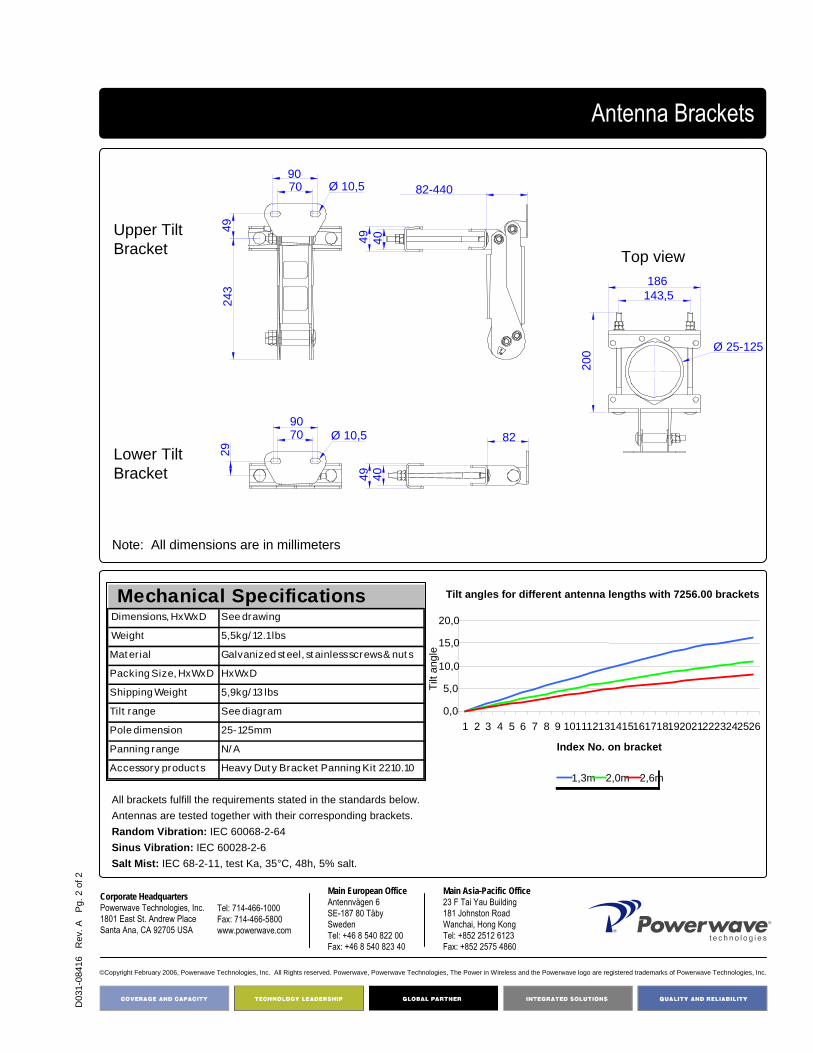
D03
1-08
416
Rev
. A
Pg.
2 o
f 2
©Copyright February 2006, Powerwave Technologies, Inc. All Rights reserved. Powerwave, Powerwave Technologies, The Power in Wireless and the Powerwave logo are registered trademarks of Powerwave Technologies, Inc.
Corporate HeadquartersPowerwave Technologies, Inc. 1801 East St. Andrew PlaceSanta Ana, CA 92705 USA
Tel: 714-466-1000Fax: 714-466-5800 www.powerwave.com
Main European OfficeAntennvägen 6SE-187 80 TäbySwedenTel: +46 8 540 822 00Fax: +46 8 540 823 40
Main Asia-Pacific Office23 F Tai Yau Building181 Johnston RoadWanchai, Hong KongTel: +852 2512 6123Fax: +852 2575 4860
Antenna Brackets
7090
Ø 10,5
4924
3
49 40
82-440
200
143,5186
Ø 25-12549 40
82
29
7090
Ø 10,5
Upper Tilt Bracket
Lower Tilt Bracket
Top view
Dimensions, HxWxD See drawing
Weight 5,5kg/ 12.1 lbs
Mat er ial Galvanized st eel, st ainless screws & nut s
Packing Size, HxWxD HxWxD
Shipping Weight 5,9kg/ 13 lbs
Tilt range See diagram
Pole dimension 25-125mm
Panning range N/ A
Accessory product s Heavy Dut y Bracket Panning Kit 2210.10
Mechanical Specifications
All brackets fulfill the requirements stated in the standards below. Antennas are tested together with their corresponding brackets.Random Vibration: IEC 60068-2-64Sinus Vibration: IEC 60028-2-6Salt Mist: IEC 68-2-11, test Ka, 35°C, 48h, 5% salt.
Note: All dimensions are in millimeters
Tilt angles for different antenna lengths with 7256.00 brackets
0,0
5,0
10,0
15,0
20,0
1 2 3 4 5 6 7 8 9 1011121314151617181920212223242526
Index No. on bracket
Tilt
angl
e
1,3m 2,0m 2,6m

D03
1-08
520
Rev
. A
Pg.
1 o
f 2
Part Number:7458.00
Antennas length:< 1.5 meter/5 feet
4168.11.33.00 Antenna BracketsLarge pole mounting adapter
Weight:9.5 kg/20,9 lbs
Powerwave large pole mounting adapter is to be used with Powerwave antennas shorter than 1.5 meter/5 feet, see table below.
Key Benefits:
• Robust and reliable design• Easy to install
Family Part Number
HBB 7720.x0/7721.x0/7722.x0/7735.x0A/7740.x0A/7745.x0AUrban 7225.0x/7226.0x/7227.0x/7228.0x/7230.0x/7231.0x/72320x/7233.0x/
7270.0x/ 7271.0x/ 7272.0x/ 7273.0x/ 7275.0x/ 7276.0x/ 7277.0x/ 7278.0xXurban 7216.0x/7217.0x/7218.0x/7255.0x/7263.0x/7281.0x/7282.0xMetro 7182.xx/7183.xx/7184.xx/7185.xx/7194.xx/7195.xx/7198.xx/7199.xx/
7200.xx/7221.xxAL antennas 7337.0x/7338.0x/7339.0x
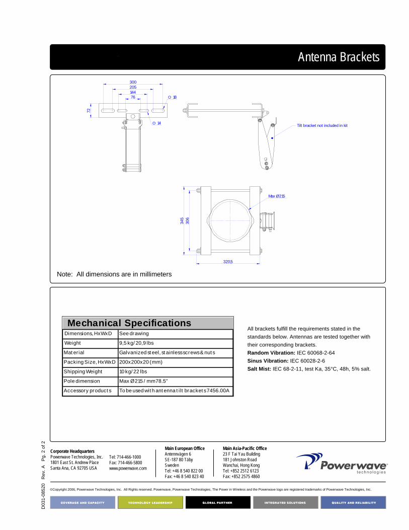
D03
1-08
520
Rev
. A
Pg.
2 o
f 2
©Copyright 2006, Powerwave Technologies, Inc. All Rights reserved. Powerwave, Powerwave Technologies, The Power in Wireless and the Powerwave logo are registered trademarks of Powerwave Technologies, Inc.
Corporate HeadquartersPowerwave Technologies, Inc. 1801 East St. Andrew PlaceSanta Ana, CA 92705 USA
Tel: 714-466-1000Fax: 714-466-5800 www.powerwave.com
Main European OfficeAntennvägen 6SE-187 80 TäbySwedenTel: +46 8 540 822 00Fax: +46 8 540 823 40
Main Asia-Pacific Office23 F Tai Yau Building181 Johnston RoadWanchai, Hong KongTel: +852 2512 6123Fax: +852 2575 4860
Antenna Brackets
Dimensions, HxWxD See drawing
Weight 9,5 kg/ 20,9 lbs
Mat erial Galvanized st eel, st ainless screws & nut s
Packing Size, HxWxD 200x200x20 (mm)
Shipping Weight 10 kg/ 22 lbs
Pole dimension Max Ø 215 / mm78.5"
Accessory product s To be used wit h ant enna t ilt bracket s 7456.00A
Mechanical SpecificationsAll brackets fulfill the requirements stated in the standards below. Antennas are tested together with their corresponding brackets.Random Vibration: IEC 60068-2-64Sinus Vibration: IEC 60028-2-6Salt Mist: IEC 68-2-11, test Ka, 35°C, 48h, 5% salt.
345
306
320,5
Max Ø215
72
76144205300
O 18
O 14 Tilt bracket not included in kit
Note: All dimensions are in millimeters

D03
1-08
417
Rev
. A
Pg.
1 o
f 2
Antenna BracketsTriple Mount Bracket
The Powerwave Triple Mount Bracket allows the mounting of three antennas on a single support for a sturdy and elegant installation. The Triple Mount Bracket permits independent mechanical and electrical tilting of each sector, offering unparalleled versatility. Antennas may be used with their standard mounting hardware, with or without mechanical tilt.
The Model 7454.00 Triple Mount Bracket is compatible with all directional Powerwave panel antennas up to 370 mm/14.5” width. Antennas shorter than 1.5m/5 feet can use the full tilt range of the 7456.00A antenna tilt bracket.
Key Features/Benefits:
• Compatible with several antenna models • Rugged design and construction • Visually appealing• Precise alignment of sector boundaries• Easy to install• Any length antenna• Perfect for stealth installations• Can be used with standard tilt brackets, 7456.00A,
included on antennas
Part Number:7454.00
Antenna width: < 370 mm/14.5”
Weight:1.5 kg/3.3 lbs

D03
1-08
417
Rev
. A
Pg.
2 o
f 2
©Copyright 2006, Powerwave Technologies, Inc. All Rights reserved. Powerwave, Powerwave Technologies, The Power in Wireless and the Powerwave logo are registered trademarks of Powerwave Technologies, Inc.
Corporate HeadquartersPowerwave Technologies, Inc. 1801 East St. Andrew PlaceSanta Ana, CA 92705 USA
Tel: 714-466-1000Fax: 714-466-5800 www.powerwave.com
Main European OfficeAntennvägen 6SE-187 80 TäbySwedenTel: +46 8 540 822 00Fax: +46 8 540 823 40
Main Asia-Pacific Office23 F Tai Yau Building181 Johnston RoadWanchai, Hong KongTel: +852 2512 6123Fax: +852 2575 4860
115
For poles Ø 75-114
64
71
19,5
Ø 9
64
71
12
1983
110
Ø 9
X
Max width for tube dim:Ø 75 mm = X max 300 mmØ 114 mm = X max 370 mm
Top view
Side view
Dimensions, HxWxD See drawing Weight 6.8 kg/15 lbsMaterial SteelTilt range See diagram. Only antennas < 1.5 m/5 feetPole dimension 75-114 mmPanning range N/AAccessory products Can be used with antenna tilt brackets 7456.00A
Mechanical Specifications
Tilt angles for different antenna lengths
0,0
5,0
10,0
15,0
20,0
25,0
30,0
35,0
40,0
1 2 3 4 5 6 7 8 9 10 11 12 13 14 15 16 17 18 19 20 21 22 23 24 25 26
Index No. on bracket
Tilt
angl
e
0,7m 1,3mThe design and the design calculations are based on Swedish Standards as follows: • Swedish building rules, BBR (last edition 1999)• Swedish design rules, BKR (last edition 1999)• Handbook for steel structures, BSK (last edition 99)
• Handbook for snow and wind loadings, BSV (last edition 97:2)
Antenna Brackets

D03
1-08
414
Rev
. A P
g 1
of 2
Part Number:2201.11
Antenna length:< 1.5 meter/5 feet
4168.11.33.00 Antenna BracketsWall and Panning Kit
Weight:0,3 kg/0,7 lbs
All Powerwave antennas shorter than 1.5 meter (5 feet) can be installed with the Powerwave wall and panning kit, 2201.11. Below is a list outlining which antennas which can use this wall and panning kit.
Key Benefits:
• Robust and reliable design• Easy to install• Easy to operate
Family Part Number
HBB 7720.x0/7721.x0/7722.x0/7735.x0A/7740.x0A/7745.x0AUrban 7225.0x/7226.0x/7227.0x/7228.0x/7230.0x/7231.0x/72320x/7233.0x/
7270.0x/ 7271.0x/ 7272.0x/ 7273.0x/ 7275.0x/ 7276.0x/ 7277.0x/ 7278.0xXurban 7216.0x/7217.0x/7218.0x/7255.0x/7263.0x/7281.0x/7282.0xMetro 7182.xx/7183.xx/7184.xx/7185.xx/7194.xx/7195.xx/7198.xx/7199.xx/
7200.xx/7221.xxAL antennas 7337.0x/7338.0x/7339.0x

D03
1-08
414
Rev
. A P
g 2
of 2
©Copyright 2006, Powerwave Technologies, Inc. All Rights reserved. Powerwave, Powerwave Technologies, The Power in Wireless and the Powerwave logo are registered trademarks of Powerwave Technologies, Inc.
Corporate HeadquartersPowerwave Technologies, Inc. 1801 East St. Andrew PlaceSanta Ana, CA 92705 USA
Tel: 714-466-1000Fax: 714-466-5800 www.powerwave.com
Main European OfficeAntennvägen 6SE-187 80 TäbySwedenTel: +46 8 540 822 00Fax: +46 8 540 823 40
Main Asia-Pacific Office23 F Tai Yau Building181 Johnston RoadWanchai, Hong KongTel: +852 2512 6123Fax: +852 2575 4860
Antenna Brackets
Dimensions, HxWxD See drawing
Weight 0,3 kg/ 0,7 lbs
Mat er ial Galvanized st eel, st ainless screws & nut s
Packing Size, HxWxD 200x200x20 (mm)
Shipping Weight 0,3 kg/ 0,7 lbs
Tilt range See diagram
Pole dimension N/ A
Panning range 5-55°
Accessory product s To be used wit h ant enna t ilt bracket s 7456.00A
Mechanical Specifications
All brackets fulfill the requirements stated in the standards below. Antennas are tested together with their corresponding brackets.Random Vibration: IEC 60068-2-64Sinus Vibration: IEC 60028-2-6Salt Mist: IEC 68-2-11, test Ka, 35°C, 48h, 5% salt.
Note: All dimensions are in millimeters
55°453525155°
5-55°100Approx.
55
Tilt angles for different antenna lengths
0,0
5,0
10,0
15,0
20,0
25,0
30,0
35,0
40,0
1 2 3 4 5 6 7 8 9 10 11 12 13 14 15 16 17 18 19 20 21 22 23 24 25 26
Index No. on bracket
Tilt
angl
e
0,7m 1,3m

D03
1-08
415
Rev
. A
Pg.
1 o
f 2
Part Number:2210.10
Antenna length:≥ 1.5 meter/5 feet
4168.11.33.00 Antenna BracketsWall and Panning Kit
Weight:1,0 kg/2,2 lbs
All Powerwave antennas with heavy duty bracket 7256.00 can be installed with Powerwave wall and panning kit, 2210.10. Below is a list outlining which antennas must use the 2210.10 wall and panning kit.
Key Benefits:
• Robust and reliable design• Easy to install• Easy to operate
Family Part Number
LBB65 747x.xxLBB90 748x.xxDHBB 776x.x0DBB65 775x.x0DBB90 777x.x0TBB65 778x.x0ALP 7804.00/7824.00/7834.00/7838.00City 7143.xx.xx.xx/7144.xx.xx.xx/7145.xx.xx.xxUrban 7218.1xXurban 7227.1xAL Antennas 7840.x0/7850.x0/7329.0x/7330.0x/
7331.0x/7332.0x/7333.0x/7334.0xAll antennas except .90 are shipped with pre-mounted brackets.

D03
1-08
415
Rev
. A
Pg.
2 o
f 2
©Copyright 2006, Powerwave Technologies, Inc. All Rights reserved. Powerwave, Powerwave Technologies, The Power in Wireless and the Powerwave logo are registered trademarks of Powerwave Technologies, Inc.
Corporate HeadquartersPowerwave Technologies, Inc. 1801 East St. Andrew PlaceSanta Ana, CA 92705 USA
Tel: 714-466-1000Fax: 714-466-5800 www.powerwave.com
Main European OfficeAntennvägen 6SE-187 80 TäbySwedenTel: +46 8 540 822 00Fax: +46 8 540 823 40
Main Asia-Pacific Office23 F Tai Yau Building181 Johnston RoadWanchai, Hong KongTel: +852 2512 6123Fax: +852 2575 4860
Antenna Brackets
Dimensions, HxWxD See drawing
Weight 1,0 kg/ 2,2lbs
Mat er ial Galvanized st eel, st ainless screws & nut s
Packing Size, HxWxD 200x200x20 (mm)
Shipping Weight 1 kg/ 2.2 lbs
Tilt range See diagram
Panning range 10-55°
Accessory product s To be used wit h ant enna t ilt bracket s 7256.00
Mechanical Specifications
All brackets fulfill the requirements stated in the standards below. Antennas are tested together with their corresponding brackets.Random Vibration: IEC 60068-2-64Sinus Vibration: IEC 60028-2-6Salt Mist: IEC 68-2-11, test Ka, 35°C, 48h, 5% salt.
Note: All dimensions are in millimeters
10-55°
Approx. 135
50
Tilt angles for different antenna lengths with 7256.00 brackets
0,0
5,0
10,0
15,0
20,0
1 2 3 4 5 6 7 8 9 1011121314151617181920212223242526
Index No. on bracket
Tilt
angl
e
1,3m 2,0m 2,6m
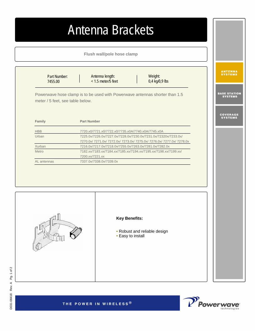
D03
1-08
418
Rev
. A
Pg.
1 o
f 2
Part Number:7455.00
Antenna length:< 1.5 meter/5 feet
4168.11.33.00 Antenna BracketsFlush wall/pole hose clamp
Weight:0,4 kg/0,9 lbs
Powerwave hose clamp is to be used with Powerwave antennas shorter than 1.5 meter / 5 feet, see table below.
Key Benefits:
• Robust and reliable design• Easy to install
Family Part Number
HBB 7720.x0/7721.x0/7722.x0/7735.x0A/7740.x0A/7745.x0AUrban 7225.0x/7226.0x/7227.0x/7228.0x/7230.0x/7231.0x/72320x/7233.0x/
7270.0x/ 7271.0x/ 7272.0x/ 7273.0x/ 7275.0x/ 7276.0x/ 7277.0x/ 7278.0xXurban 7216.0x/7217.0x/7218.0x/7255.0x/7263.0x/7281.0x/7282.0xMetro 7182.xx/7183.xx/7184.xx/7185.xx/7194.xx/7195.xx/7198.xx/7199.xx/
7200.xx/7221.xxAL antennas 7337.0x/7338.0x/7339.0x

D03
1-08
418
Rev
. A
Pg.
2 o
f 2
©Copyright 2006, Powerwave Technologies, Inc. All Rights reserved. Powerwave, Powerwave Technologies, The Power in Wireless and the Powerwave logo are registered trademarks of Powerwave Technologies, Inc.
Corporate HeadquartersPowerwave Technologies, Inc. 1801 East St. Andrew PlaceSanta Ana, CA 92705 USA
Tel: 714-466-1000Fax: 714-466-5800 www.powerwave.com
Main European OfficeAntennvägen 6SE-187 80 TäbySwedenTel: +46 8 540 822 00Fax: +46 8 540 823 40
Main Asia-Pacific Office23 F Tai Yau Building181 Johnston RoadWanchai, Hong KongTel: +852 2512 6123Fax: +852 2575 4860
Antenna Brackets
Dimensions, HxWxD See drawing
Weight 0,4 kg/ 0,9 lbs
Mat er ial Galvanized st eel, st ainless screws & nut s
Packing Size, HxWxD 200x200x20 (mm)
Shipping Weight 0,4 kg/ 0,9 lbs
Tilt range N/ A
Pole dimension 40-100 mm/ 1.57"-3.9"
Panning range N/ A
Accessory product s To be used wit h ant enna t ilt bracket s 7456.00A
Mechanical SpecificationsAll brackets fulfill the requirements stated in the standards below. Antennas are tested together with their corresponding brackets.Random Vibration: IEC 60068-2-64Sinus Vibration: IEC 60028-2-6Salt Mist: IEC 68-2-11, test Ka, 35°C, 48h, 5% salt.
Note: All dimensions are in millimeters
10,5
3
104
45
70
70
Ø 8,5

4168 Product Index
Antennas
RET Filters 7010.00
7020.00
7030.00
7070.xx
7060.00
7060.10
9215.01
LGP141nn
LGP144nn
LGP145nn
LGP164nn
LGP195nn
LGP219nn
TMA Clean Site
7488.06
7700.00
7700.06
7701.00
7701.02
7701.06
7720.x0
7721.x0
7721.10
7722.x0
7735.x0
7740.x0
7745.x0
7750.x0
7752.x0
7755.x0
7760.x0
7762.x0
7765.x0
7766.x0
7780.00
7782.00
7785.00
LGP104nn
LGP121nn
LGP132nn
LGP136nn
LGP138nn
LGP167nn
LGP185nn
LGP166nn
LGP192nn
LGP215nn
Single System
Dual System
Triple System
4168.11.33.00
4168.11.33.02
4168.11.33.03
4168.11.33.06
4168.11.33.52
7216.03
7217.03
7217.04
7217.11
7218.13
7218.14
7218.15
7218.19
7226.03
7226.04
7227.03
7227.04
7227.06
7228.13
7228.14
7228.16
7228.18
7230.04
7231.04
7231.06
7232.04
7232.07
7233.14
7233.16
7233.18
7255.03
7255.04
7263.01
7263.04
7270.02
7271.02
7271.03
7272.02
7273.02
7273.03
7276.02
7277.02
7278.02
7281.02
7281.04
7282.03
7329.00
7329.06
7330.00
7330.02
7330.04
7330.06
7331.00
7331.02
7331.04
7331.06
7336.00
7336.10
7471.00
7472.00
7473.00
7476.00
7476.02
7476.06
7477.00
7477.02
7477.06
7478.00
7478.02
7478.06
7481.00
7482.00
7483.00
7486.00
7486.02
7486.06
7487.00
7487.02
7487.06
7488.00
7488.02
7804.00R2A