BROADBAND COMMUNICATION SYSTEM FOR POLISH LAND FORCES - GLOBAL CHARACTERISTICS.
26
BROADBAND COMMUNICATION SYSTEM FOR POLISH LAND FORCES - GLOBAL CHARACTERISTICS
-
Upload
beatriz-anctil -
Category
Documents
-
view
218 -
download
1
Transcript of BROADBAND COMMUNICATION SYSTEM FOR POLISH LAND FORCES - GLOBAL CHARACTERISTICS.

BROADBAND COMMUNICATION SYSTEM
FOR POLISH LAND FORCES - GLOBAL CHARACTERISTICS

CONTENTS
1. Schedule of work
2. Other projects
3. Main features of the system- global description
- proposed technologies
4. System’s architecture
- global architecture
- functional subsystems
- example of topology
5. Nodes’ architecture
- architecture of WAS node
- architecture of LAS node
- devices
- shelters
6. Conclusions

SCHEDULE OF WORK
1. Beginning of the project – 1999.
2. Operational requirements and conception – 1999/2000.
3. „Testbed” – 2001/2002.
4. Tactical and Technical Requirements – end of 2002.
5. Technical documentation of devices and shelters – 2003.
6. Prototypes of the shelters – 2004/2005.
7. Testing and national certification – 2006.
8. Implementation and developing 2006/2007.

TESTBED

OTHER PROJECTS
Tactical Communications for the Land Combat Zone - Post-2000
(TACOMS Post-2000) - NATO nations
Warfighter Information Network (WIN-T) - USA
RITA-2000, ATTILA - France
Cormorant, Falcon - UK
TITAAN - Netherlands
TASMUS - Turkey

ProgramProgram
TACOMS Post - 2000TACOMS Post - 2000
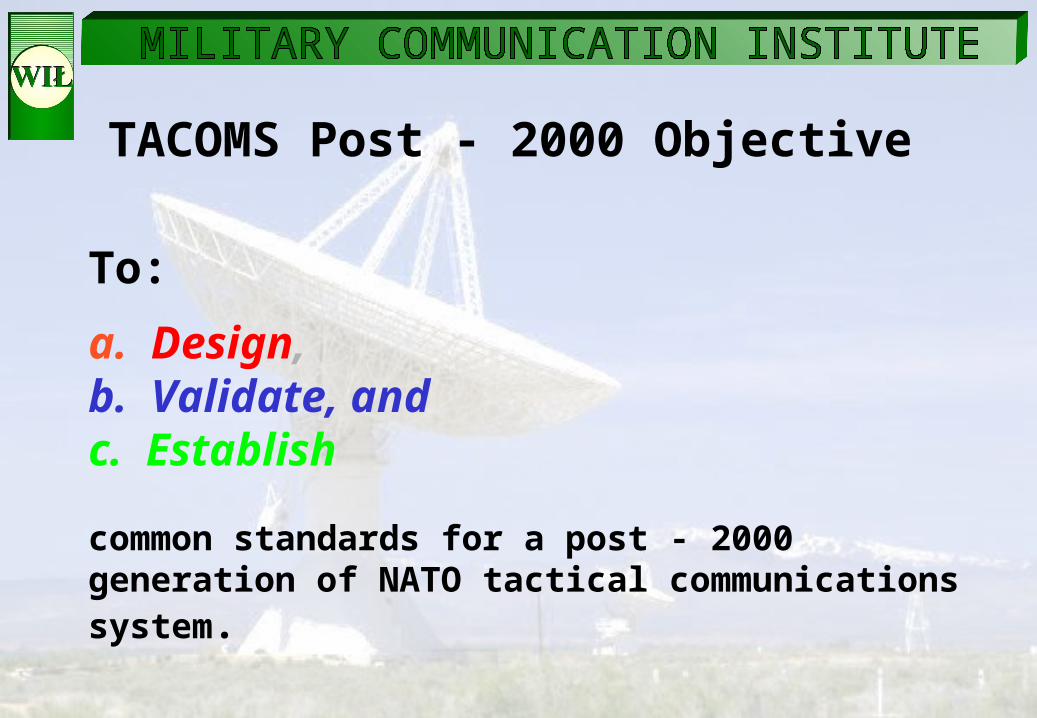
TACOMS Post - 2000 Objective
To:
a. Design,b. Validate, andc. Establish
common standards for a post - 2000 generation of NATO tactical communications system.

MAIN FEATURES OF THE SYSTEM
- required level of interoperability (TP2K)
- interworking with stationary communication systems
- interoperability with existing systems
- COTS principle
- the latest technologies
- advanced telecommunications services
- management
- security
- open for modification

Technologies used in the system
used in the trunk and access nodes. ISDN switches first of all
should provide phone services for subscribers.
used in local area network based on TCP/IP family
protocols. This technology should provide data transmission in the system.
used in the trunk and access nodes. ATM switches are the
main elements of these nodes. Purpose - integration of different
technologies used in nodes, provision of effective trunks’ utilization in the
system and quality of service.

SYSTEM’S ARCHITECTUREWAS - Wide Area SubsystemLAS - Local Area SubsystemMS - Mobile SubsystemLTB - LANTELBOXAP - Access Point
TrSh - Transmission Shelter
SwSh - Switching Shelter
Sw-ASh - Switching – Access Shelter
RAPSh - Radio Access Point Shelter
SMCS - System Management and Control Subsystem
CNR - Combat Net Radio

SECURITY SUBSYSTEM

NODES’ ARCHITECTURE
STM-1
STM-1
E1 E1E1
digital(ISDN)
CVSD systems
PBX(ISDN)
Router(IP)
LAN
LOS HCLOS
SAT
DSTG
Z
Z
Z
E1
analog
Subscribers
other(PCM)
systems
LOS HCLOS
WAS node
ATMSwitch

Location of the shelters in the trunk node

LAS node
STM-1
STM-1
E1, E2
E1 E1
digital(ISDN)
CVSD systems
PBX(ISDN)
Router (IP)
LAN
HCLOS
SAT
DSTG
Z
Z
Z
E1
analog
Subscribers
other(PCM)
systems
LOS HCLOS
Switch
video
Ethernet
LAN
ATMSwitch
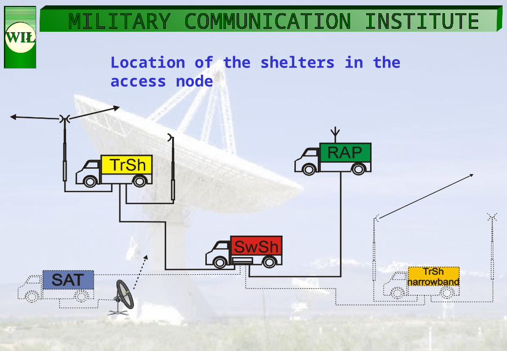
Location of the shelters in the access node

BROADBAND COMMUNICATION SYSTEM –
SHELTERS

SYSTEM’S ARCHITECTURE
WAS - Wide Area SubsystemLAS - Local Area SubsystemMS - Mobile SubsystemTN - Trunk NodeAN - Access Node
WAS
TN
TN
Radio networks
RAP
PBX LAN LAN
T T T T T T
DSTG
Existing
systems
External
systems
TN
AN
TN
LAS
MS
TN
TN
SECURITYSECURITY
SMCS
SwSh-t
SwSh-a
TrSh
HCLOS

DEVICES IN SHELTERS
- ATM switch
- ISDN switch
- Access Integrator
- Bulk Encryption Device
- Multiplexer
- Media Converter
- Gateway IP/ISDN
- Base Station WLAN
- Radio Relay

ATM Switch - TAKOM
• Element of the WAS and LAS networks• CBR, VBR, UBR services’ support• PVC, SPVC and SVC support• Resources’ management: e.g. CAC, UPC• PNNI, ILMI, UNI signaling support• IISP, PNNI routing• SNMPv3 management• AESA addressing support• Interoperation with IP: LANE, CLIP
Access switch• STM-1MM – 2 ports• E1 IMA – 16 ports (4x4)
• Eth 10/100TX – 6 ports• Eth 100FX – 7 ports• ISDN card – 4 x S0
Trunk switch• STM-1MM – 2 ports• E1 IMA – 48 ports (12x4)
• Eth. 10/100TX – 7 ports• Eth. 100FX – 6 ports• ISDN card – 4 x S0

ISDN Switch – DGT 3450–1 WW
• ISDN bearer services’ support• Supplementary services’ support• DSS1 signaling on digital subscribers’ lines• DSS1 and QSIG signaling on trunks• DSTG gateway (STANAG 4578 ed. 2)• STANAG 5046 i STANAG 4214 numbering support• SNMPv3 management
Access Switch• E1 PRI – 8 ports• 4578 E1 PRI – 2 ports• 4206/EUROCOM D1 – 2 ports• S0 – 16 ports• UK0 – 16 ports
Trunk Switch• E1 PRI – 4 ports• 4578 E1 PRI – 2 ports• 4206/EUROCOM D1 – 2 ports• S0 – 16 ports• UK0 – 16 ports

Access Integrator - AI ATM-ISDN • Element of the Switching – Access and Switching – Trunk Shelters
• Provides an effective interworking between ISDN switches through ATM network
• ATM trunking using AAL1 support
• QSIG and DSS1 to UNI 4.0 conversion support
• STANAG 5046 to ATM AESA address conversion support
• Interoperation with ATM switch through STM-1 interface
• Interoperation with ISDN switch through two ISDN PRI interfaces
• CBR, VBR, UBR services’ support
• PVC, SPVC and SVC support
• Resources’ management: e.g. CAC, UPC
• SNMPv1 management

The view of the shelter

IMPLEMENTATION OF TACOMS Post INTERFACES IN SWITCHING SHELTER

Example of application

Example of application

QUESTIONS?