BRITISH BATTLESHIPS 1914–18 (1) - Educación Holística Force...CONTENTS INTRODUCTION 4 DESIGN AND...
50
ANGUS KONSTAM ILLUSTRATED BY PAUL WRIGHT BRITISH BATTLESHIPS 1914–18 (1) The Early Dreadnoughts © Osprey Publishing • www.ospreypublishing.com
-
Upload
truongdiep -
Category
Documents
-
view
220 -
download
6
Transcript of BRITISH BATTLESHIPS 1914–18 (1) - Educación Holística Force...CONTENTS INTRODUCTION 4 DESIGN AND...

ANGUS KONSTAM ILLUSTRATED BY PAUL WRIGHT
BRITISH BATTLESHIPS 1914–18 (1)The Early Dreadnoughts
© Osprey Publishing • www.ospreypublishing.com

NEW VANGUARD 200
BRITISH BATTLESHIPS 1914–18 (1)The Early Dreadnoughts
ANGUS KONSTAM ILLUSTRATED BY PAUL WRIGHT
© Osprey Publishing • www.ospreypublishing.com

CONTENTS
INTRODUCTION 4
DESIGN AND DEVELOPMENT 5The Pre-Dreadnoughts
The Big Gun Battleship
Dreadnought
Rebuilding the Fleet
The Bellerophon Class
The St Vincent Class
Neptune
The Colossus Class
Agincourt
SPECIFICATIONS 25
FIGHTING POTENTIAL 29Fire Control
The Main Battery
Protection
WARTIME MODIFICATIONS 38Dreadnought
Bellerophon Class
St Vincent Class
Neptune
Colossus Class
Agincourt
WARTIME SERVICE 44Dreadnought
Bellerophon Class
St Vincent Class
Neptune
Colossus Class
Agincourt
BIBLIOGRAPHY 47
INDEX 48
© Osprey Publishing • www.ospreypublishing.com

4
INTRODUCTION
Few warships can lay claim to having changed the course of history. Fewer still were so revolutionary that they gave their name to a type of ship. Only one combined that honour with the even greater one of having an era of naval history named after her. That ship was HMS Dreadnought. Following her completion in 1906 she not only became the most powerful warship in the world, but she also rendered all previous battleships obsolete. They were referred to by the somewhat derogatory term ‘pre-dreadnoughts’. Nothing more clearly demonstrates the revolutionary aspect of the Dreadnought than the fact that virtually overnight these earlier battleships were deemed antediluvian, and no longer worthy of a place in a modern battle fleet.
Dreadnought was the brainchild of two men – the British First Sea Lord Admiral Sir John Fisher, and Sir Philip Watts, the Director of Naval Construction (DNC). Watts had a vision – the creation of a battle fleet of multi-turreted big gun battleships, capital ships that were larger and more powerful than any warship that had come before. His visionary ship was also faster than its predecessors, as it relied on steam turbines for propulsion. Fisher not only supported Watts, but he ensured that the first ship of this new type – the Dreadnought – was approved and built in record time.
This in itself was a gamble. Although the Royal Navy was by far the largest fleet in the world, and the Dreadnought levelled the playing field – Britain had to build a new fleet of dreadnoughts from scratch, and build them faster than her foreign rivals. As a result the country embarked on a whirlwind
BRITISH BATTLESHIPS 1914–18 (1)
THE EARLY DREADNOUGHTS
The launch of HMS
Dreadnought in February 1906
ushered in a new era in naval
warfare. Not only was she the
world’s first all big gun
battleship, but she led to a re-
evaluation of how war would
be waged at sea.
© Osprey Publishing • www.ospreypublishing.com
5
programme of ship construction, and by 1909 the first of these dreadnoughts was completed. Others would follow, all carrying Dreadnought’s homogenous main armament of 12-inch guns. These new capital ships would form the backbone of Britain’s Grand Fleet during World War I.
The war itself has been blamed in part on the naval shipbuilding race between Britain and Germany. As early as 1909 German naval planners had worked out that the most favourable ratio of dreadnought strength for them – 16 German to 22 British ‘dreadnoughts’ – would take place in the autumn of 1914. After that Britain would be able to out-build its continental rival. This then became another factor in the drift towards war. The effectiveness of Watts’ ‘dreadnought’ design would soon be tested in battle.
DESIGN AND DEVELOPMENT
While Dreadnought was clearly a revolutionary warship, this was due to the amalgam of several new features, such as turbine propulsion, a homogenous main armament and modern gunnery fire control. However, these were all features that had already been tried out elsewhere, or had been considered by the Admiralty before Sir Philip Watts’ design was approved. While the impact the Dreadnought had might have been revolutionary, the ship herself was more evolutionary than anything else – the next step in the development of the Edwardian capital ship.
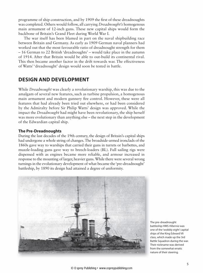
The Pre-DreadnoughtsDuring the last decades of the 19th century, the design of Britain’s capital ships had undergone a whole string of changes. The broadside-armed ironclads of the 1860s gave way to warships that carried their guns in turrets or barbettes, and muzzle-loading guns gave way to breech-loaders (BL). Full sailing rigs were dispensed with as engines became more reliable, and armour increased in response to the mounting of larger, heavier guns. While there were several wrong turnings in the evolutionary development of what became the ‘pre-dreadnought’ battleship, by 1890 its design had attained a degree of uniformity.
The pre-dreadnought
battleship HMS Hibernia was
one of the ‘wobbly eight’ capital
ships of the King Edward VII
class, which made up the 3rd
Battle Squadron during the war.
Their nickname was derived
from the somewhat erratic
nature of their steering.
© Osprey Publishing • www.ospreypublishing.com

6
When Sir William White became the Director of Naval Construction in 1885 the First Sea Lord Sir Arthur Hood requested he produce what became the Royal Sovereign class, which entered service at the end of the decade. These ships carried barbette-mounted guns – essentially open-topped turrets, except for the last of the eight-ship class, HMS Hood (1891). There White was allowed to mount the vessels’ four 13½-inch guns in two twin turrets. This design then formed the basis for the Majestic class of the 1890s, but these later ships were better protected than their predecessors. They used Harvey armour, a new type of caser-hardened steel that provided the same protection for half the thickness of the steel plate carried in earlier warships. The weight saved was used to provide additional armoured protection around the turret barbettes. This was the same form of barbette protection White would provide for the Dreadnought. By then, however, new and better forms of steel had become available.
The nine battleships of the Majestic class proved highly successful, but they used fully enclosed barbettes rather than proper turrets. They looked similar, but were less effective than a fully traversable turret. White was allowed to fit an improved version of the enclosed barbette in the next batch of six battleships, known as the Canopus class. Like the Majestic class, these battleships used 12-inch breech-loading guns Mark VIII, which proved superior to earlier guns of larger calibre. The gun houses were protected by the new Krupp armour, which proved more effective than Harvey’s steel. However, the steel plates were harder to bend than the earlier type, which led to an angular appearance to the gun mountings. This box-like style would be repeated in the turrets of the Dreadnought and her successors. Effectively they were fully fledged gun turrets in all but name.
In the Formidable and London classes White was able to use an improved version of the 12-inch gun, mounted in fully functioning turrets. Like the Canopus and Duncan classes, these battleships were fitted with a new type of high-pressure boiler, which improved the efficiency of their engines. They were followed by the eight battleships of the King Edward VII class, which were essentially slightly larger versions of the Duncan class. Unlike them,
This illustration of the power
of HMS Dreadnought is taken
from the souvenir booklet of
the Coronation Review of 1911,
and is an attempt by the
Admiralty to justify the expense
of their dreadnought-building
programme.
© Osprey Publishing • www.ospreypublishing.com

7
though, they also carried a powerful secondary armament of four 9.2-inch guns, as well as the 6-inch guns carried by the earlier battleships. This was in response to the introduction of similar powerful secondary batteries in the warships of other navies, and was a development that was imposed on Sir William White rather than one he advocated. The same provision of powerful secondary guns was repeated in the two ships of the Lord Nelson class.
While these classes – a total of 39 new battleships built over the course of a decade – contained minor improvements, they were essentially very similar to each other. They were all high-freeboard battleships, carrying four 12-inch guns mounted in two turrets, with adequate armoured protection to fight ships armed with a similar armament, they were reasonably well powered, and they all displaced less than 17,000 tons. The uniformity of their design was a reflection of White’s original concept for a modern turreted battleship of this kind.
In effect he created a homogenous battle-fleet, but one that would soon be rendered obsolete by White’s successor. While these ships were never tested in action against an enemy battle-fleet, similarly designed ships built for the Japanese certainly proved their worth at the battle of Tsushima in 1905.
By then, White had retired, and in 1902 Sir Philip Watts had become the new Director of Naval Construction. His first task was to supervise the final design and building of the two Lord Nelson-class battleships, and it was Watts who redesigned them to carry ten 9.2-inch guns apiece, mounted in their own turrets rather than in casemate batteries. While he was an advocate of this calibre of gun, he also realized that this was merely a step in the right direction. If these secondary turrets carried 9.2-inch guns, then a similar design could just as easily accommodate more 12-inch turrets in their stead. The Lord Nelson and the Agamemnon can therefore be seen as precursors of the dreadnought. For this reason they are sometimes referred to as semi-dreadnought battleships, to set them apart from the less well-armed battleships of Sir William White’s battle-fleet.
The Big Gun BattleshipAs the Director of Naval Construction, Sir Philip Watts was well aware of naval developments overseas, and he realized that if Britain failed to act soon, then others would take the lead in the design of multi-turreted big gun battleships. His arguments proved unappealing to many in the Admiralty, as any change to the naval status quo risked the loss of Britain’s numerical superiority over her potential rivals. Fortunately he found a kindred spirit in Sir John Fisher, who became the new First Sea Lord in 1904. Fisher had already earned a reputation for innovation. As Controller of the Navy he had been instrumental in the adoption of the improved water-tube boiler, and as Second Sea Lord he set about improving the training given to young officers. As First Sea Lord, ‘Jacky’ Fisher could turn his attention to the reform of Britain’s battle-fleet – reforms that were entirely in keeping with Sir Philip’s ideas.
In May 1905 the Japanese began building two new battleships, carrying a mixture of 12-inch and 10-inch guns. While these were similar to the Lord Nelson class, it suggested that it was only a matter of time before they began building a capital ship exclusively armed with 12-inch guns. Watts then learned that the Americans were about to lay down two new battleships – the South Carolina and the Michigan – which would be armed with eight 12-inch
© Osprey Publishing • www.ospreypublishing.com

8
guns, mounted in four twin turrets. The Italians were also contemplating the building of a similar class of ship. It was clear to Watts and Fisher that the time had come to act.
After reviewing Watts’ plans, Fisher decided that not only should the proposed new battleship be built, but that it should be produced with all speed and the utmost secrecy, in order to ‘steal a march’ on Britain’s rivals, as Fisher himself put it. Plans for the dreadnought
were drawn up by Watts, assisted by the naval architects John Narbeth and Henry Deadman, both of whom were advocates of the multi-turreted big gun battleship. In fact both men had lobbied for an all 12-inch gun armament for the Lord Nelson class, but had been overruled by Watts’ predecessor. Now the three naval architects had a free rein, as not only did Fisher support them, but so too did the Director of Naval Gunnery. Together these men would turn their collective dream into reality.
Fisher was also an advocate of steam turbines. They had been used successfully in smaller warships, and the First Sea Lord now planned to have them adapted to power capital ships. The Admiralty’s Engineer, Chief Sir John Durston, proposed using Parsons turbines, and together the two men overcame doubters to ensure that the new warship would be powered by these largely untried machines. The Committee on Designs first examined Watts’ draft plans in January 1905, and by March it had approved them, albeit with a few modifications.
Contrary to the DNC’s recommendations, they altered the layout of the belt armour, which meant that when fully laden with coal the thickest part of Dreadnought’s armoured belt would be located below the waterline,
leaving only the thinner belt above it for protection above the waterline. Just as crucially, they altered Watts’ turret configuration, leaving her two wing turrets with a more limited field of fire than Watts would have wished. Plans to superimpose the turrets – to raise ‘B’ and ‘X’ turrets so they could fire over ‘A’ and ‘Y’ turrets – were abandoned as there was not enough time to overcome the construction problems of this radical configuration if the Dreadnought was going to enter service ahead of her foreign rivals.
British gunners, still wearing
their protective anti-flash
hoods and gloves, watch as the
German High Seas fleet sails
into captivity in November
1918. This represented a great
testimony to the achievements
of British seapower during
World War I.
Royal Marines drilling on the
quarterdeck of a St Vincent-
class battleship as it lies at
anchor in Scapa Flow during
the early years of World War I.
As well as providing boarding
and landing parties, the
marines also served as
gun crews.
© Osprey Publishing • www.ospreypublishing.com

9
Still, the modified plans were approved, and construction began in early October 1905. The aim was to make the process of construction as speedy as possible. For his part Watts simplified the vessel’s hull structure as much as he could, using standard-sized plates and bulkhead designs that had already been created for the Lord Nelson class. Fisher pressured the staff of Portsmouth Royal Dockyard to complete construction in record time, and made sure that the shipyard was supplied with the materials, men and expertise it needed.
Dreadnought was launched in February 1906, just four months after her keel plate was first laid down. Fitting out took another ten months, but in October 1906 she was ready for her basin trial, where her engines were tested and their alignment checked. For publicity purposes this was heralded by the Admiralty as her completion date – a year after being laid down – although the new vessel was only fully completed in December. Still, even this total of 14 months was a new shipbuilding record, and one that has never been repeated. Much of the credit for this must go to Sir John Fisher. He supervised the whole process, and ensured that the Dreadnought got first priority in terms of resources. His decision to use four 12-inch turrets originally earmarked for the two Lord Nelson-class battleships may also have helped to slightly speed up construction time. As a result, the completion of these two semi-dreadnoughts was delayed, and they both took over two years to fit out. However, Dreadnought was built in half the time usually taken for battleship construction, and she entered service a full four years before her American or Japanese rivals.
Dreadnought When she entered service in December 1906, Dreadnought was the largest battleship in the world, displacing 21,845 tons when fully laden with coal and stores. Her ten 12-inch guns were mounted in five twin turrets, three on her centreline (one forward, one amidships and one aft), plus one mounted on either side of her forward superstructure. These last two turrets had an arc of fire of 180°, which meant that a maximum of four turrets could fire at a target at any one time. Unusually, this configuration meant that three turrets could fire at a target directly ahead of the vessel.
The dirty business of coaling
ship was a regular occurrence
on board the dreadnoughts
of the British battle-fleet.
The switch from coal to fuel
oil would obviate the need for
these messy and unpleasant
duties.
© Osprey Publishing • www.ospreypublishing.com

10
This powerful battery had twice the firepower of any battleship then in service. Just as importantly, it was capable of being controlled centrally, a development that was necessary given the number of 12-inch guns she carried. The Dreadnought was the ultimate product of the scientific gunnery revolution that had dominated naval thought over the past decade. This central control made it possible to calibrate the guns together to produce a closely bunched salvo. This could then be ‘spotted’ onto the target. On ‘pre-dreadnought’
battleships, one team controlled the fire of each gun. Now one team controlled the fire of all of Dreadnought’s turrets.
Fisher and Watts had also made a conscious decision to avoid mounting a secondary battery. Instead, Dreadnought carried a battery of 24 12-pounders, which were designed to counter the threat posed by small fast torpedo boats. It was soon found that these mountings were too exposed to the blast of the main guns, particularly those on the turret roofs. They were removed in 1910. Finally she was fitted with submerged torpedo tubes, two capable of firing on each broadside, and one that pointed astern of the vessel.
Her protection of Krupp-style ‘cemented’ armour was concentrated in a protective belt, which was almost 11 inches (28cm) wide amidships, reducing to 6 inches forward and 4 inches aft. This was designed to protect the hull from 12-inch calibre shells, but as already noted the belt stopped short of the main deck, and the upper portion of the hull was protected by just 8 inches of steel plate. The barbettes and turrets were well protected, with 8–11 inches of armour, as was the main conning tower.
HMS DREADNOUGHT, HMS TEMERAIRE
The launch of HMS Dreadnought (top) in 1906 rendered all existing battleships virtually obsolete
and ushered in a new era in naval warfare. She even gave her name to this new age, and to a new
type of battleship that shared Dreadnought’s homogenous main armament, turbine propulsion
and modern fire control. Ironically the first 12-inch gun ‘dreadnought’ of them all was also the
only one to miss their real baptism of fire at Jutland. Shortly before the battle, Dreadnought was
attached to a pre-dreadnought squadron guarding the eastern approaches to the English
Channel, and so she missed the battle. This depiction of her shows Dreadnought as she looked
after emerging from her refit in early 1916.
Like her two Bellerophon-class sister ships, HMS Temeraire was essentially a copy of the
Dreadnought. They differed in two main respects. The two classes could readily be identified as
they had two tripod masts rather than just one, the foremast moved forward of the first funnel to
improve visibility. Secondly, while Dreadnought lacked any secondary armament, it was felt this
was an asset if the vessel was attacked by torpedo boats. Therefore Temeraire and her identical
sisters carried a battery of 16 4-inch guns mounted in their superstructure, all in single gun
mountings. Here Temeraire is shown on the eve of Jutland.
A
In the engine rooms of the
dreadnoughts, stokers and
trimmers shovelled coal from
bunker to boiler furnace in
conditions that can best be
described as grim. Engine room
staff were great advocates of
the switch from coal to oil.
© Osprey Publishing • www.ospreypublishing.com

11© Osprey Publishing • www.ospreypublishing.com

12
However, as there was no appreciation of the dangers of long-range plunging fire, her upper deck was relatively lightly armoured, with 3 inches of Krupp non-cemented armour over her ‘vitals’, and 1½ inches elsewhere. As the belt armour extended below the waterline, her designers felt that Dreadnought would be invulnerable to attack by torpedoes. They failed to take into account the latest developments in this form of weapon, and during the war events were to prove the designers wrong.
She was powered by the new 4-screw Parsons turbine, which had a rotary action, thereby reducing vibration within the hull. The high-pressure steam was provided by three groups of six Babcock & Wilcox water-tube boilers, which generated 23,000 shp (steam horse power). This was sufficient to give Dreadnought a top speed of 21 knots. She could be powered by coal or fuel oil, which gave her a useful degree of versatility. When filled to capacity with 2,900 tons of coal, her bunkers gave her a radius of action of 6,600 nautical miles at normal cruising speed, while her fuel tanks had an additional capacity of 1,120 tons. In 1907 Dreadnought set off on an extended cruise to the Mediterranean, the Caribbean and back. Her engines performed magnificently, and there was none of the mechanical trouble many critics had expected from so innovative a design. Mechanically, Dreadnought had proved her worth.
Another innovative feature of the Dreadnought was due to Fisher. In almost all previous British warships the officers were accommodated in the stern of the vessel, as they had been since the age of sail. Fisher proposed moving them forward, to beneath the fighting heart of the ship – the bridge, the gunnery control position and the wireless transmitting office. While this made perfect sense, to the navy of the time it looked and felt wrong. It was even claimed that it upset the natural balance of the ship. While this
HMS Dreadnought had a less
substantial forward
superstructure than later
dreadnoughts, but they all had
a similarly exposed bridge
flanked by bridge wings, and
an open-topped compass
platform above it. In this view
the main fire control position
can clearly be seen at the base
of her foretop.
© Osprey Publishing • www.ospreypublishing.com

13
arrangement was repeated in subsequent classes of dreadnoughts, the idea was quietly dropped in all dreadnoughts designed after the Orion class.
When she entered service, Dreadnought’s first commander, Captain Reginald Bacon, declared that she was very stable and her hull made an excellent gun platform. Critics had doubted whether the vessel could cope with the stress imposed by firing her main broadside. In fact she took this in her stride, as the ship was well-founded. Bacon’s two main criticisms were that she was ‘stiff’ – there was little movement in her hull – and this made her an uncomfortable vessel in rough weather. She was also difficult to pull out of a turn at high speed, due to a poorly balanced rudder. More seriously, it was found that smoke from her forward funnel often obscured the view from the gun control platform mounted on the foremast, and also swirled around the bridge. This impeded the fighting ability of the ship, and while steps were taken to deal with the problem in later dreadnoughts, the Dreadnought herself continued to suffer from this defect.
Although this had an impact on gun direction, it was seen as little more than a minor form of teething trouble – something that was almost inevitable given the speed with which Dreadnought was designed and built. What is far more remarkable was that the case for the big gun battleship had been made. Fisher and Watts had built the most powerful battleship in the world. What they had to do now was to repeat their success by building an equally powerful battle-fleet.
Builder Laid Down Launched Completed Fate
Dreadnought Portsmouth Dockyard
2 October 1905
10 February 1906
December 1906
Sold and broken up 1921
Rebuilding the FleetBuilding the Dreadnought was only the start. It was inevitable that foreign rivals would build their own ‘dreadnoughts’, and so if Britain wanted to maintain her naval supremacy then it was imperative that Britain should build more dreadnoughts – and build them at a faster rate than her rivals. The process that had begun on No. 5 building slip in Portsmouth Dockyard would continue until 1920. By then 35 battleships and 11 battlecruisers had been built, at a cost to the British taxpayer of £151 million. The last of these ships was the 42,000-ton battlecruiser Hood, which entered service just as the first of these dreadnoughts were being decommissioned and sold for scrap. After World War I there was simply no more need for this vast battle-fleet. Post-war parsimony and a belief that this had been ‘the war to end all wars’ led to naval reduction treaties and the scaling down of the wartime fleet.
In 1906 all this lay in the future. After Dreadnought was launched that February, the Admiralty set about rebuilding the battle-fleet. Fisher described the existing capital ships as vessels that, when compared to Dreadnought, could neither fight nor run away. The aim was to replace these older battleships with dreadnoughts, but until these new warships were built the older pre-dreadnoughts would have to serve as a stopgap. The first problem was persuading the government that it needed to fund this ambitious shipbuilding programme. During the fiscal year of 1906–07, the new Liberal government of Henry Bannerman-Campbell approved the building of six new dreadnoughts, which would effectively be repeats of the original Dreadnought.
© Osprey Publishing • www.ospreypublishing.com

14
Fisher and his colleagues in the Admiralty proved adept at encouraging press support for their dreadnought-building programme. In their 1906 election manifesto the Liberals had committed themselves to reducing military and naval expenditure. The need to build a dreadnought fleet made this impossible, as public opinion rallied behind the navy. The 1908 slogan ‘We want eight and we won’t wait’ – referring to new dreadnoughts – became a political catchphrase that Bannerman-Campbell’s successor Herbert Asquith was unable to ignore. Therefore in 1909 the Chancellor Lloyd George was forced to raise taxes in order to push through the Admiralty’s building programme, and to
institute the welfare programme that was the cornerstone of Asquith’s Liberal reforms. The building of four new dreadnoughts was duly approved in 1909, and as the war clouds loomed others would follow.
For those who wanted the Royal Navy to maintain its naval position these new dreadnoughts could hardly enter service soon enough. In Germany an ambitious shipbuilding programme had already been approved in 1906, as part of Admiral Tirpitz’s planned expansion of the Imperial German Navy. The launch of Dreadnought forced Tirpitz to abandon his programme, and instead to use this earmarked funding to build Germany’s own class of dreadnoughts. Laid down in 1907, the four dreadnoughts of the Nassau class would enter service in 1910. By the time that work began on them, Britain was preparing to launch her first class of three new dreadnoughts. So began a naval arms race between the two naval powers that many saw as a major contributory factor to the outbreak of World War I.
HMS BELLEROPHON AT JUTLAND, 1916
HMS Bellerophon joined the fleet in February 1909, the first dreadnought battleship to enter service
since the commissioning of the Dreadnought just over two years earlier. Those two years were a time
of feverish shipbuilding, and, like her predecessor, Bellerophon was built in record time – Portsmouth
Navy Yard had her ready for launching within eight months of laying her down.
When the Grand Fleet was reorganized in August 1914 she became part of the 4th Battle
Squadron, where she was eventually joined by her sisters Superb and Temeraire.
At Jutland (31 May 1916) the squadron consisted of two divisions, each of four dreadnoughts.
Bellerophon was in the 4th Division, commanded by Vice-Admiral Doveton Sturdee, the victor
of the battle of the Falkland Islands (1914). At around 7.25pm Bellerophon was in the centre of
Admiral Jellicoe’s long line of dreadnoughts, and together with Agincourt at the rear of the line
was among the first ships to spot the enemy battlecruisers and to open fire on them. At the time
she was steaming towards the north-east and about to alter course 90˚ to starboard, following
Jellicoe’s order for the fleet to move east to ‘cross the T’ of the approaching German battle fleet.
This scene shows Bellerophon firing that first broadside at the German battlecruisers, which at the
time were 18,000 yards away to the south-east.
B
A floating gunnery target being
prepared for use prior to a
gunnery exercise, with HMS
Bellerophon pictured behind it.
Fisher laid great store on
gunnery training, and
consequently the quality of
British gunnery improved
dramatically in the years before
the outbreak of the war.
© Osprey Publishing • www.ospreypublishing.com

15© Osprey Publishing • www.ospreypublishing.com

16
The Bellerophon ClassSir John Fisher adopted a very simple policy when it came to building new dreadnoughts. The emphasis was on speed rather than innovation, and so before 1909 the basic design of the Dreadnought would serve as a template for the first two classes of dreadnoughts. Each would incorporate slight improvements and modifications to the original design, based on the evaluation of the Dreadnought’s performance and added into the plans after the ships were launched. However, in order to maintain the shipbuilding momentum these changes would be minimal. The first of them would virtually be repeats of the Dreadnought: the most visible difference was that their foremasts were moved in front of the forward funnel, and a mainmast was erected in front of the after funnel.
The three dreadnoughts of the Bellerophon class were all laid down during the winter of 1906–07, with work on Bellerophon herself starting just as Dreadnought was entering service. These three new dreadnoughts were all launched between July and November 1907. They were completed in early 1909, which meant they all took between 26 and 28 months to build – twice
the time taken to build Dreadnought. The new arrangement of the masts was designed to cure the problem of smoke billowing around the gunnery fire control position, but this was a failure – smoke still swirled forward from the forward funnel, while the after gunnery control position was often completely obscured by smoke from both funnels.
Internally, the bulkhead arrangement was an improvement on that in Dreadnought, which only protected her magazines from flooding. In the Bellerophon class, watertight bulkheads were located at intervals along the length of the vessel. This improved level of underwater protection was in part an admission that the threat posed by submarines and torpedoes was greater than the designers had first imagined. At 18,800 tons these vessels had a slightly larger displacement than Dreadnought, but were her equivalent in terms of speed and performance.
Another modification was the inclusion of a secondary battery. The lack of one on Dreadnought had proved unpopular with the Admiralty, and so Sir Philip Watts included a small battery of 16 4-inch quick-firing (QF)
guns, mounted in the superstructure and initially on the turret tops. The latter were soon moved, as they couldn’t be manned if the main guns were to be used. Apart from the continued problem of smoke obscuring the spotting positions, the Bellerophon class was deemed a success, and during their sea trials the ships proved fast and reliable.
By the early summer of 1909 they joined Dreadnought in the battle-fleet. By then,
Sir John Jellicoe (1859–1935)
may have been described as
the only man who could lose
the war in an afternoon,
but he was also the admiral
responsible for forging Britain’s
dreadnought fleet into an
effective battle-winning
weapon.
The Bellerophon-class
dreadnought Temeraire,
displaying her pre-war funnel
markings. Under this system
the funnels of Bellerophon were
unmarked, while Superb carried
two bands on her fore funnel
and none on her after one.
© Osprey Publishing • www.ospreypublishing.com

17
however, the naval arms race was well under way, as Germany, the United States and Japan had all begun building their own dreadnoughts. France, Russia, Austro-Hungary and even Brazil and Argentina would follow. It was now more imperative than ever that Britain should maintain its naval lead.
Builder Laid Down Launched Completed Fate
Bellerophon Portsmouth Dockyard
3 December 1906
27 July 1907 February 1909
Sold and broken up 1921
Superb Elswick, Tyneside
6 February 1907
7 November 1907
May 1909 Sold and broken up 1923
Temeraire Devonport Dockyard
1 January 1907
24 August 1907
May 1909 Sold and broken up 1921
The St Vincent ClassBy the start of 1907 the Dreadnought was in service, and the Admiralty had the funds it needed to expand its dreadnought-building programme. Fisher made the decision to repeat the design of the Bellerophon class; in fact these ships were ordered roughly at the same time as the vessels of the previous class, and were funded by the same government budget. Like their predecessors they incorporated a number of modifications to the original Dreadnought design, based on the post-completion evaluation of her performance. However, these were minor, as speed of construction was more important than innovative design. This made the three dreadnoughts of the St Vincent class the last British warships whose basic design would be virtually identical to the original Dreadnought.
The most significant difference between these vessels and their
In this late war photograph of
HMS Bellerophon, a flying-off
platform can be seen fitted to
the roof of ‘A’ turret. While the
use of such devices may still
have been a novelty, they
represented an important step
forward in the way naval
warfare would develop during
the post war years.
While the dreadnoughts of the
Bellerophon and St Vincent
classes looked similar, they
could be readily identified by
their funnels. Those of the
Bellerophon class were of an
equal size, while the fore funnel
of the St Vincent class was
smaller than the after funnel.
This photograph shows the
funnel arrangement of HMS
Vanguard as she lies at anchor
in Scapa Flow.
© Osprey Publishing • www.ospreypublishing.com

18
predecessors was that a new version of the 12-inch gun was used, the Mark XI rather than the Mark X. The barrel of this new version of the 12-inch gun was slightly longer than the earlier model, and theoretically this made the gun a little more accurate. Unfortunately, while the weapon was more powerful and had a higher muzzle velocity, it did not prove a success, as it was actually less accurate at long range than the Mark X weapon. To make matters worse, this problem was not discovered until these ships and the other 12-inch gun dreadnoughts that followed them had already been built.
Slight reductions in both the beam and the draught of these St Vincent-class dreadnoughts were used to compensate for their extra ten feet of length, a modification imposed by the length of the new gun barrels. There was also a slight increase in propulsive power, but, given the larger displacement of these ships compared with the previous dreadnoughts, the effect on their performance was marginal.
The location of the masts remained the same as in the previous class, so the visibility problems caused by smoke obscuring the after fire control position were the same as those which plagued the gunners in the earlier dreadnoughts. As in the Bellerophon class, these dreadnoughts of the St Vincent class carried a secondary battery of 4-inch QF guns. The size of the secondary battery was also increased from 16 to 20 guns, and as before these quick-firing weapons were placed in sponson mounts, placed in casemates sited in the superstructure. By this stage, the notion of mounting these guns in exposed positions on the turret tops or the open deck had been abandoned.
While the three dreadnoughts of the St Vincent class were effective and powerful ships, they served to underline the two big problems of the original Dreadnought design. First, the configuration of the main armament was far from ideal. In the United States, the first of the South Carolina class of dreadnoughts had been laid down with eight guns mounted in four twin turrets, arrayed along the centreline of the ship. As ‘B’ and ‘X’ turrets were ‘superimposed’ or raised up a deck so they could fire over ‘A’ and ‘Y’ turrets,
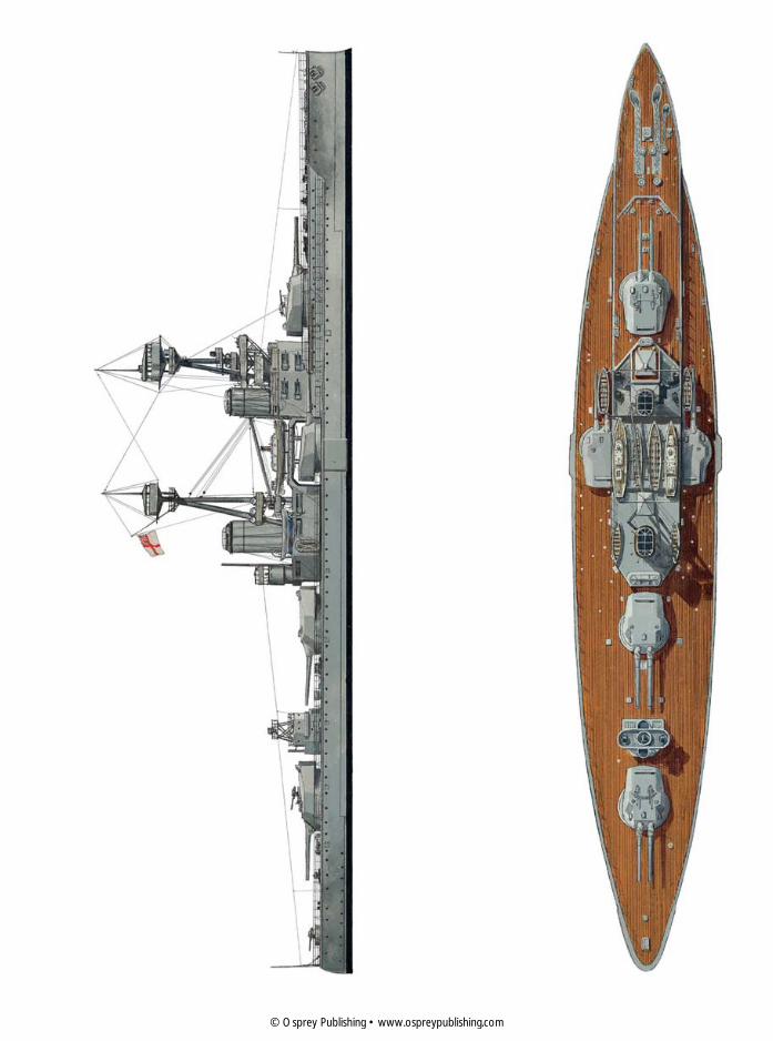
HMS COLLINGWOOD
HMS Collingwood was a St Vincent-class dreadnought, a class of three vessels which were very
similar to those of the Bellerophon class. By the time she was ordered in 1907 doubts had been
raised about the turret configuration, but the Admiralty rushed through these new ships before
the last of the previous Bellerophon class had even been laid down. Therefore the only real
difference was the replacement of the 12-inch guns with a slightly longer Mark XII variant – an
experiment that was not particularly successful as they proved less accurate than their
predecessors at long range. Another problem inherited from the Bellerophon class was the siting
of the after fire control position on the mainmast, as spotting was often hindered by smoke from
the forward funnel.
The only modifications made to Collingwood before 1916 were the removal of two 4-inch guns
and the lowering of her topmasts. After Jutland she was refitted, and cowlings (known as clinker
screens) fitted to the tops of her funnels. Her two sisters only had a clinker screen fitted to the
forward funnel. In this plate we see her from two aspects – broadside on and in plan view, to show
the layout of her turrets. This turret layout was shared by both Dreadnought and the Bellerophon-
class vessels.
C
The St Vincent-class
dreadnought HMS Vanguard
as she looked when she first
entered service in early 1910.
Her topmasts were lowered
before the outbreak of the war
to hinder enemy range-finding,
and her largely useless after
fire control position in her
mainmast was removed.
© Osprey Publishing • www.ospreypublishing.com
19© Osprey Publishing • www.ospreypublishing.com

20
this meant that these first American dreadnoughts carried one turret less than the British dreadnoughts but matched them in firepower. Just as importantly, the Americans solved the problem of smoke obscuring the fire control positions by mounting them on the top of high latticework towers. Clearly, British designers could learn something from their foreign rivals.
Builder Laid Down Launched Completed Fate
Collingwood Devonport Dockyard
3 February 1907
7 November 1908
April 1910 Sold and broken up 1922
St Vincent Portsmouth Dockyard
30 December 1907
10 September 1908
May 1909 Sold and broken up 1921
Vanguard Vickers, Barrow-in-Furness
2 April 1908 22 February 1909
February 1910
Accidentally destroyed 9 July 1917
Neptune The biggest criticism levelled at the Dreadnought and her immediate successors was that the disposition of the main armament was wasteful. Only eight of the ten main guns could fire at any one time, as the two wing turrets were placed on either side of these vessels’ superstructure. This arrangement was taken one step further in the first German dreadnoughts, the four ships of the Nassau class that were laid down in late 1907. They carried 12 guns, mounted in six twin turrets, but all except the fore and aft turrets were blocked by superstructure. This supremely wasteful configuration meant that only eight guns could fire at a target.
For some reason Watts and his team were unwilling completely to abandon their concept of wing turrets, and so their solution was something of a compromise. Still, it was an improvement over what had gone before, and went some way towards making better use of the firepower of the British dreadnoughts. The solution was to stagger the two wing turrets slightly, and to remove the superstructure from their inboard side. This meant that the guns in the wing turrets had a limited ability to fire on the opposite broadside. Therefore, as long as the enemy was directly abeam of the vessel, all of her ten guns could be fired at it.
A second innovation – one that was adopted after studying the configuration of the South Carolina class – was to move the location of
HMS Neptune as she appeared
when she first entered service
in 1911. The following year her
forward funnel was heightened
by 6 feet, and at the start of the
war her forward flying bridge
was removed to avoid the risk
of debris from it obscuring ‘P’
wing turret on her port side.
The flying bridge over ‘Q’ turret
was retained throughout the
war.
© Osprey Publishing • www.ospreypublishing.com

21
‘X’ turret aft slightly and to superimpose it over ‘Y’ turret. This actually represented a more important development than the re-siting of the wing turrets, as it paved the way for the gun configuration mounted along the centreline used in British ‘super dreadnoughts’ and in all subsequent British battleships. In late 1908, however, when plans for the Neptune were being drawn up, this was still a recent and largely untried innovation.
Strangely, one of the main catalysts for the adoption of this turret configuration was South American political rivalry. Fearing that the Argentines were about to commission the building of a dreadnought in a North American shipyard, the Brazilians ordered two dreadnoughts of their own from the British yards of Armstrong and Vickers. They were designed to carry 12 12-inch guns in six twin turrets, two of which were wing turrets of the kind mounted in Dreadnought, while the other four were mounted in the bow and the stern, with ‘B’ and ‘X’ turrets superimposed over ‘A’ and ‘Y’ turrets. This meant that the designers in these two private yards had already addressed the problems posed by superimposing one turret behind the other. All the Director of Naval Construction and his team had to do with Neptune was to adopt the same design for their own ship. They were able to justify their decision by maintaining that this configuration avoided having to make the vessel’s hull any longer, having increased its length already in order to provide the cross-deck clearance for the wing turrets.
This left the designers with one more problem. On previous dreadnoughts the boat deck had been located between the funnels, but this space was now left clear for the gun turrets. The solution was to mount the boat deck on flying bridges, which spanned the gap between the two funnels, and between the after funnel and the after superstructure. This design was repeated in the subsequent Colossus class, but it was soon realized that the cross-deck firing of the wing turrets caused damage to the superstructure, and the boats on the flying bridge were particularly vulnerable. The forward flying bridge was therefore removed shortly before the outbreak of the war.
What was more of a success was the propulsion system fitted in Neptune. She was provided with cruising turbines, which reduced consumption of coal at normal
The armour protection
provided for Neptune was
concentrated in her belt, which
was 10 inches thick at the
waterline (marked in black
here) and 11 inches around her
barbettes and turret faces.
Other areas of her hull had less
protection.
The gaps in the superstructure
and the flying bridge
arrangement on HMS Neptune
were designed to give ‘P’ and ‘Q’
wing turrets the ability to fire
across her decks, but as can be
seen here the cross-deck arc of
fire was severely restricted.
© Osprey Publishing • www.ospreypublishing.com

22
cruising speed, while her improved Parsons turbines and Yarrow boilers were only slightly more powerful than those fitted to earlier dreadnoughts, but she proved faster than her predecessors, making over 22½ knots during her sea trials. Like the previous dreadnoughts, she was designed to operate using coal or fuel oil. Another improvement was the provision of stronger watertight bulkheads below the waterline, the aim being to permit the ship to continue fighting even after her hull had been pierced by shells or torpedoes. When Neptune entered service in January 1911 she was arguably the most advanced dreadnought in the world. Given the pace of change during the naval arms race, this was a mantle she held for less than a year.
Builder Laid Down Launched Completed Fate
Neptune Portsmouth Dockyard
19 January 1909
30 September 1909
January 1911 Sold and broken up 1922
The Colossus ClassBy 1909, the naval arms race had intensified to such an extent that the Liberal government in Britain was unable to withstand demands to counter the launch of new German dreadnoughts with new ones of their own. As a result, two extra dreadnoughts were ordered by the Admiralty in 1909, to be supplied by private shipyards. In addition, funding was approved for a whole new class of dreadnought, designed to carry the 13.5-inch gun. While the DNC and his team began planning these new ‘super dreadnoughts’, in order to save time and effort it was decided that the two extra dreadnoughts would be built along the same lines as the Neptune.
HMS Hercules pictured under
way soon after she entered
service in late 1911. In 1912 her
forward funnel was raised to
reduce the impact of smoke
billowing around the bridge
and spotting tops. Unlike
Neptune, the two Colossus-class
dreadnoughts retained both of
their flying bridges until 1917.
© Osprey Publishing • www.ospreypublishing.com

23
This meant they also used the same en echelon arrangement for their wing turrets ‘P’ and ‘Q’, but these were placed slightly closer together than those in Neptune in order to leave more room for the forward superstructure and for the casemate guns mounted there. They were slightly heavier than Neptune, and so to save weight the foremast was moved abaft of the forward funnel. As in Neptune, this was considered high enough to avoid the worst of the funnel smoke, and the arrangement was repeated in the first of the new ‘super dreadnoughts’ that followed. It also harked back to the mast arrangement used in the original Dreadnought.
While Neptune and all other British dreadnoughts had been fitted with 18-inch torpedoes, mounted in firing chambers below the waterline, in the Colossus class these were replaced with more powerful 21-inch torpedoes, which in turn meant a slight reconfiguration of the hull to accommodate the somewhat larger torpedo rooms. The Admiralty demanded that the designers provide additional protection around the gun turrets and barbettes, but Watts and his team were well aware that any significant increase in displacement would mean that much of the armoured belt would be below the waterline, and so to compensate they reduced the thickness of the belt towards the bow and stern.
The two Colossus-class battleships entered service in the summer of 1911, too late to take part in the Coronation Fleet Review of King George V in June. On 24 June the might of the Royal Navy was assembled off Spithead, along with warships representing the leading foreign naval powers. This was an opportunity for the Royal Navy to show off its new dreadnought fleet, an imposing group of eight battleships and four battlecruisers. Few spectacles could have been as imposing, or better demonstrated that Britain was still the world’s leading maritime power.
Builder Laid Down Launched Completed Fate
Colossus Scotts, Clydeside
8 July 1909 9 April 1910 July 1911 Sold and broken up 1928
Hercules Palmers, Tyneside
30 July 1909 10 May 1910 August 1911 Sold and broken up 1921
Agincourt Even as the two Colossus-class dreadnoughts were being laid down, the DNC was busy designing the next generation of dreadnought. These vessels, designed to carry the 13.5-inch gun, would soon be deemed ‘super dreadnoughts’ and would represent a dramatic increase in the power and the scale of the battleship. Colossus and Hercules would be the last dreadnoughts armed with 12-inch gun to be ordered by the Admiralty. However, they wouldn’t be the last vessel of this kind to enter service.
When the Brazilians commissioned the building of their two dreadnoughts, the Argentines responded by ordering
Probably the most unusual
dreadnought in the Grand
Fleet, HMS Agincourt lacked
the armoured protection of
the dreadnoughts designed by
Sir Philip Watts, but its armour
was concentrated where it
mattered most. It also had
75 per cent more firepower
than Dreadnought.
© Osprey Publishing • www.ospreypublishing.com

24
two dreadnoughts of their own from shipyards in the United States. The Brazilians countered this move by ordering a third dreadnought, one designed to outgun and outfight its Argentine rivals. Designed in the Armstrong shipyard on Tyneside, this dreadnought went through several design and armament changes before she was laid down in late 1911, and in her final configuration she was built to carry no fewer than 14 12-inch guns in seven twin turrets. She was going to be called the Rio de Janeiro, but a lack of funds prompted the Brazilian government to abandon the project soon after work had begun.
She was sold to the Turks in early 1914, who promptly renamed her the Sultan Osman I. By that time this powerful dreadnought was being fitted out, and she was finished shortly before the outbreak of the war. However, in August 1914 the First Lord of the Admiralty Winston Churchill ordered that she be detained in Britain until Turkey’s position in the war became clear. When Turkey sided with the Central Powers the dreadnought was impounded and handed over to the Royal Navy. The navy removed the large flying bridge spanning her two funnels and commissioned her into the service. She duly became the Agincourt, the longest battleship in the fleet, and the last one to carry 12-inch guns.
These guns themselves were something of a novelty. Unlike the Admiralty 12-inch guns carried in other dreadnoughts, Agincourt carried Armstrong-designed ‘Type W’ guns, which were operated in a different manner. Most notably they were designed so that all loading and firing operations could be carried out by the pull of a single lever, rather like the gearing system of a manual car. While some naval critics derided Agincourt by calling her the ‘Gin Palace’, few could argue that she packed a powerful broadside. As all 14 of her guns were mounted on her centreline and so could be fired together, her full broadside was a spectacle to behold, according to eyewitnesses.
Builder Laid Down Launched Completed Fate
Agincourt Armstrong, Tyneside
September 1911
22 January 1913
August 1914 Sold and broken up 1922
HMS Agincourt as she appeared
when she first entered service
with the Grand Fleet in
September 1914. This awkward-
looking arrangement of her
masts was altered after Jutland,
when her mainmast was
removed and a topmast added
to the top of the central derrick
post between her funnels.
© Osprey Publishing • www.ospreypublishing.com
25
SPECIFICATIONS
Dreadnought
Length 527 feet overall
Beam 82 feet
Draught 31 feet (fully laden)
Displacement 18,110 tons (21,845 tons fully laden)
Propulsion Four Parsons steam turbines, 18 Babcock & Wilcox boilers, generating 23,000 shp
Maximum speed 21 knots
Range 6,620 nautical miles at 10 knots
Armament Ten 12-inch Mark X BL guns in five twin turrets
24 12-pdr 18 cwt Mark 1 QF guns in single mounts
Five submerged torpedo tubes, carrying 18-inch torpedoes
Protection Belt: 4–11 inches
Turret faces, barbettes and conning tower: 11 inches
Deck: 1½–3 inches
Complement 695–773 officers and men
Bellerophon Class
Length 526 feet overall
Beam 82½ feet
Draught 27 feet 3 inches (mean lading)
Displacement 18,800 tons (22,102 tons fully laden)
Propulsion Four Parsons steam turbines, 18 Babcock & Wilcox or Yarrow boilers, generating 23,000 shp
Maximum speed 20¾ knots
Range 5,720 nautical miles at 10 knots
Armament Ten 12-inch Mark X BL guns in five twin turrets
16 4-inch QF guns in single mounts
Four 3-pdr saluting guns in single mounts
Three submerged torpedo tubes, carrying 18-inch torpedoes
Protection Belt: 5–10 inches (Bulkheads: 8 inches)
Barbettes: 5–9 inches
Turret faces: 11 inches
Conning tower: 8–11 inches
Deck: ½–4 inches
Complement 733 officers and men
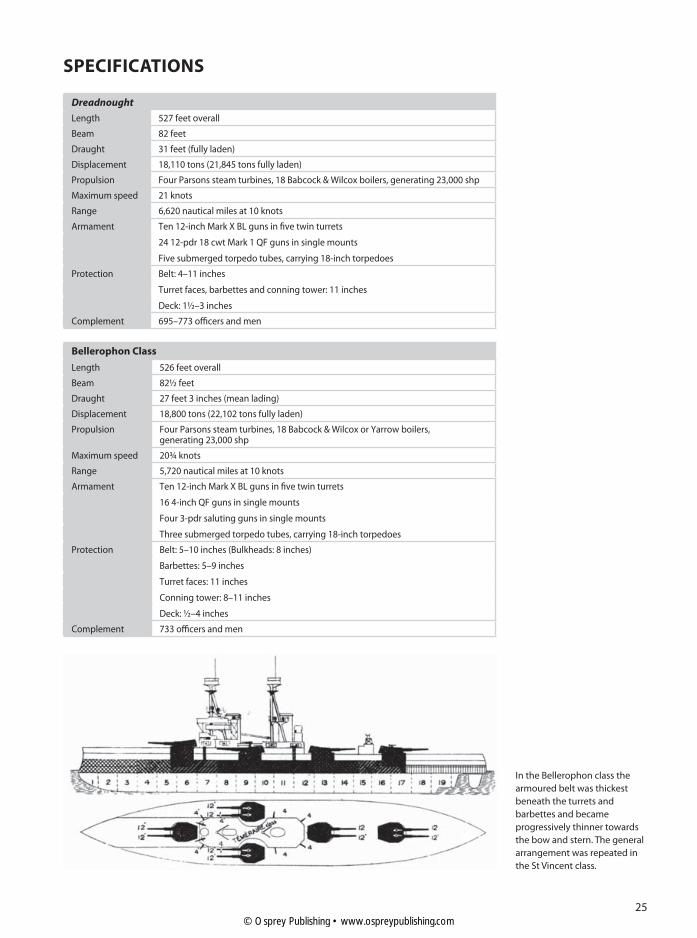
In the Bellerophon class the
armoured belt was thickest
beneath the turrets and
barbettes and became
progressively thinner towards
the bow and stern. The general
arrangement was repeated in
the St Vincent class.
© Osprey Publishing • www.ospreypublishing.com

HMS DREADNOUGHT
If any single warship could be said to have trannsformed naval warfare, then it was HMS Dreadnought. The brainchild of
Admiral ‘Jackie’ Fisher, Dreadnought was the first ‘all big gun battleship’. This meant that she stood out from existingt
battleships by having a main gun battery of a uuniform calibre, arrayed so the vessel could fire a broadside of ten guns, or
six guns over her bow or stern. A typical ‘pre-ddreadnought’ battleship carried just four guns in two twin turrets. Not only
did this give Dreadnought broadside firepowerr 2½ times as powerful as her contemporaries, but these guns were also t
supported by advanced gunnery direction andd fire control equipment, which increased the accuracy of her salvos.
Small guns were also carried to protect the neww battleship from attack by torpedo boats. Her propulsion systems were
just as revolutionary as her weaponry. Dreadnoought was driven by modern steam turbines, giving her a top speed in t
excess of 21 knots, which made her faster thann most of her contemporaries. Dreadnought was built in just 14 months,
in great secrecy. As a result, when Dreadnoughht entered service she was vastly superior to any other warship afloat.t
While she saw little action during her career, her design spawned an entirely new generation of battleships,
and gave her name to a type of ship that would dominate naval warfare for a generation.
This cutaway view of her is based on her appeaarance when she first entered service in December 1906.
D
1. Forecastle, anchor cables and steam capstan
2. Ammunition hoist
3. 12-inch BL gun Mark X (two per turret)
4. Turret barbette
5. Turret traversing mechanism
6. Turret hydraulics
7. Turret working chamber
8. 12-pdr QF guns (several throughout ship)
9. Turret gun house
10. Conning tower
11. Bridge
12. Compass platform
13. Searchlight (several throughout ship)
14. Foremast and spotting top
15. Funnels
16. Boat deck boom
17. Boat deck
18. Mainmast and after lookout station
19. After conning tower
20. Quarterdeck
21. Rudder
22. Propeller (one of two)
23. Steam turbine (one of four)
24. Boiler (one of 18)
25. Engine room trunking
26. Double bottom
27. Compressed air tanks
28. Cordite charge hopper
29. Shell room (one of two per turret)
30. Cordite magazine
31. Forward torpedo tubes
32. Bread room and other stores
33. Forward torpedo room
34. Mine store
35. Ram bow
KEY15
16
17
18
19
20
21 22 23 24 25 26
© Osprey Publishing • www.ospreypublishing.com

123
4
5
6
7
8
9
10
11
12
13
14
27 28
29 30 31 32 33 34 35
© Osprey Publishing • www.ospreypublishing.com

28
St Vincent Class
Length 536 feet overall
Beam 84 feet
Draught 27 feet 11 inches (mean lading)
Displacement 19,560 tons (23,030 tons fully laden)
Propulsion Four Parsons steam turbines, 18 Babcock & Wilcox or Yarrow boilers, generating 24,500 shp
Maximum speed 21 knots
Range 6,900 nautical miles at 10 knots
Armament Ten 12-inch Mark XI BL guns in five twin turrets
20 4-inch QF guns in single mounts
Four 3-pdr saluting guns in single mounts
Three submerged torpedo tubes, carrying 18-inch torpedoes
Protection Belt: 7–10 inches (Bulkheads: 4–8 inches)
Barbettes: 5–9 inches
Turret faces: 11 inches
Conning tower: 8–11 inches
Deck: ¾–3 inches
Complement 718 officers and men
Neptune
Length 546 feet overall
Beam 85 feet
Draught 28 feet 6 inches (deep lading)
Displacement 19,680 tons (22,720 tons fully laden)
Propulsion Four Parsons steam turbines, 18 Yarrow boilers, generating 25,000 shp
Maximum speed 21 knots
Range 6,330 nautical miles at 10 knots
Armament Ten 12-inch Mark XI BL guns in five twin turrets
16 4-inch QF guns in single mounts
Four 3-pdr saluting guns in single mounts
Three submerged torpedo tubes, carrying 18-inch torpedoes
Protection Belt: 2½–10 inches (Bulkheads: 4–8 inches)
Barbettes: 5–9 inches
Turret faces and control tower: 11 inches
Deck: ¾–3 inches
Complement 759 officers and men
HMS Vanguard at anchor in
early 1914. She sports two red
funnel recognition bands. Her
sisters were identified by white
bands on their after funnel –
one band on Collingwood and
two on St Vincent. This
recognition system was
discontinued in August 1914.
© Osprey Publishing • www.ospreypublishing.com

29
Colossus Class
Length 546 feet overall
Beam 85 feet
Draught 28 feet 9 inches (deep lading)
Displacement 20,225 tons (23,050 tons fully laden)
Propulsion Four Parsons steam turbines, 18 Babcock & Wilcox boilers (Yarrow boilers in Hercules), generating 25,000 shp
Maximum speed 21 knots
Range 6,680 nautical miles at 10 knots
Armament Ten 12-inch Mark XI BL guns in five twin turrets
16 4-inch QF guns in single mounts
Four 3-pdr saluting guns in single mounts
Three submerged torpedo tubes, carrying 21-inch torpedoes
Protection Belt: 7–11 inches (Bulkheads: 4–10 inches)
Barbettes: 4–11 inches
Turret faces and control tower: 11 inches
Deck: 1¾–4 inches
Complement 755 officers and men
Agincourt
Length 671 feet 6 inches overall
Beam 89 feet
Draught 27 feet (mean lading)
Displacement 27,500 tons (30,250 tons fully laden)
Propulsion Four Parsons steam turbines, 22 Babcock & Wilcox boilers, generating 34,000 shp
Maximum speed 22 knots
Range 4,500 nautical miles at 10 knots
Armament 14 12-inch Mark XIII BL guns in seven twin turrets
20 6-inch Mark XI QF guns in single mounts
Two 3-inch Mark I AA guns in single mounts
Three submerged torpedo tubes, carrying 21-inch torpedoes
Protection Belt: 4–9 inches (Bulkheads: 4–8 inches)
Barbettes: 3–9 inches
Turret faces and control tower: 12 inches
Deck: 1–2½ inches
Complement 1,115 officers and men
FIGHTING POTENTIAL
What set the Dreadnought apart from her predecessors was her armament – a homogenous big gun battery. She entered service at a time when naval analysts were wrestling with the new possibilities offered by fighting gun battles at much greater ranges than before. More powerful guns meant ships needed to carry thicker armour, which in turn meant a requisite increase in propulsive power. Once the genie was out of the bottle, naval designers, naval officers and taxpayers alike were forced to deal with the consequences.
Advocates of long-range naval gunnery such as Captain Sir Percy Scott were instrumental in developing the tools necessary to control the fire of big gun batteries at long ranges. The problem was that as range and firepower increased, so too did the complexity of aiming the guns. Hitting a target at long range involved too many variables and represented too
© Osprey Publishing • www.ospreypublishing.com
30
complex a problem for human gunners to solve. Therefore, gunnery fire control devices were used to solve these problems and to make the most of the firepower available to these ships. These entered service from 1907 onwards, and their use required a steep learning curve for officers and gunners alike. However, by 1914 Britain’s dreadnought fleet had become thoroughly proficient in these new devices and in the waging of this new form of long-range gunnery duel. Two years later it would demonstrate the effectiveness of its gunnery at Jutland.
Fire ControlWhile every ship’s company sailing into action was prepared to receive and deal with damage inflicted by the enemy, its main focus was to engage the enemy with its main guns. This is why they were there, risking their lives in a long-range gunnery duel – to engage and destroy the enemy.
The way this was achieved was simple in concept, but decidedly complex in its detail. The aim was to make the most of the dreadnought’s firepower by firing the entire ship’s main battery together, as a single unit. This was achieved through the use of gunnery direction, or director firing. This form of fire control involved an elaborate and integrated system of spotters, rangefinders,
electro-mechanical calculating machines, timekeepers, internal ship communications, guns and directors. It also relied on new
developments, such as the hydraulic engines that enabled gun turrets to be trained round, and the guns held in position,
trained towards the enemy.Director Firing relied on all these components
working together to produce the information the gunners needed to aim their guns and repeatedly hit the enemy ship. The whole sequence began with a pair of binoculars. First, lookouts in the spotting top would sight the enemy, and would report its approximate course and bearing. The dreadnought would generally
be sailing in company with the rest of the fleet, so other units would probably have already made an initial
sighting, and the dreadnoughts would be steaming towards a known contact. In this situation, information
would be passed between ships by signal flag or light.
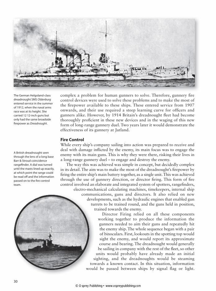
The German Helgoland-class
dreadnought SMS Oldenburg
entered service in the summer
of 1912, when the naval arms
race was at its height. She
carried 12 12-inch guns but
only had the same broadside
firepower as Dreadnought.
A British dreadnought seen
through the lens of a long base
Barr & Stroud coincidence
rangefinder. A dial was turned
until the masts lined up exactly,
at which point the range could
be read off and the information
passed on to the fire control
team.
commudeve
tut
stow
woul
© Osprey Publishing • www.ospreypublishing.com

31
While wireless communications could be used, these tended to be limited to contact between senior commanders and scouting forces for fear of giving away too much information to the enemy.
Stabilized rangefinders in the gun director would swing on to the bearing and more detailed information would start to be passed down to the transmitting station located below the main deck. As the relative position of the ship and her target were constantly changing, this information on range and bearing needed to be constantly updated. Determining range was relatively straightforward, and was found using a Barr & Stroud coincidence rangefinder. The problem came when smoke from the funnels or the guns obscured the vision of the rangelayer. That was why it was imperative to keep spotting positions as free of funnel smoke as possible.
Bearing was found by simply reading off a bearing on a track beneath a binocular sighting device. A similar set of information was provided from the after torpedo director position, which despite its name acted as an auxiliary gun director position. This information was then passed on, where it would be converted into the bearing and elevation information the gunners needed. It would also tell them how far to ‘lead’ the target to make sure that after 10–20 seconds of flight the shells would land on target rather than where it was when the guns were fired.
This conversion process was where the mechanical computers stepped in. In the transmitting station located safely below decks a team operated two large mechanical devices – the Dumaresq Rate-Solver and the Dreyer Fire Control Table. On one side of the fire control table was the bearing plotter, which was used constantly to feed in changes in the enemy ship’s bearing, and the range tuner did the same for its range. These were duly fed into the Dreyer and the Dumaresq devices. The Dumaresq was used to calculate deflection – the apparent lateral movement of the target and the range. When the range, bearing and speed of the firer and the target were mechanically entered, the machine used this to produce a vector representing the relative motion of the two ships. This resulted in a pair of co-ordinates – range and deflection.
The Dreyer Fire Control Table
Mark III was introduced in 1913
and was used to absorb range,
bearing and deflection data,
plus any other relevant
information such as wind and
course changes, and then to
send this information to the
gun turrets.
© Osprey Publishing • www.ospreypublishing.com
32
This information was then displayed on the Dreyer’s mechanical plotting table, which provided a visual representation of changes in range and deflection as well as incorporating other data suppl ied f rom the rangefinders. Another o p e r a t o r e n t e r e d information on the wind, which provided another component that needed to be plotted in order to make the shells land on target. Finally a spotting corrector entered in any changes of information called in by the spotting officer, when the observed shot was seen to fall left, right, up or down from the target. His job was an important one, as he could read the information coming from the plotters
and could quickly realise if anything was amiss – for instance when someone had entered in the wrong information. As he could see the target and monitor its movement, he acted as a useful addition to the mechanical process being carried on below decks, where nobody could even see the enemy.
All this mechanical calculation took the seven-man operating team a matter of seconds to complete. The resulting information was read out on the totalizer, which produced readings of total deflection as well as information on wind or spotting corrections or the degree of ‘lead’ required. This information was then transmitted both electro-mechanically and by telephone to the gun director. There the data would be translated into gun bearing and information. This would then be transmitted to the gun turrets, where the information would be used to train the guns.
Another problem was that on a typical 12-inch gun dreadnought the barrels of ‘A’ and ‘Y’ turret could be as much as 400 feet apart. This meant that if all the shells fired on the same angle and bearing, and the guns were accurate, the shells would land in a 400-foot long area rather than on the point the gun director wanted. The solution was to use a convergence corrector to alter the gun training data slightly, so that the guns would all aim at the same point, ideally right on top of the enemy ship.
The gunlayer could read the required elevation angle on his elevation receiver, and would use a handwheel to elevate the gun accordingly. Another trainer used a similar device to train the turret round onto its required bearing. The guns were then ready to fire. When the order came to open fire (the term ‘shoot’ was used in the Royal Navy at the time), the layer in the director would pull his trigger, and all the guns would fire in a co-ordinated
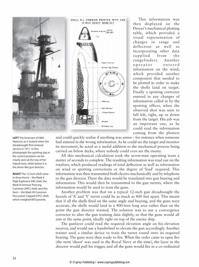
LEFT The foremast of HMS
Neptune, as it looked when the
dreadnought first entered
service in 1911. In this
photograph the spotting top or
fire control position can be
clearly seen at the top of her
tripod mast, while below it is
the drum-like gun director.
RIGHT The 12-inch shell came
in three forms – the Mark II
High Explosive (HE) shell, the
Mark VI Armour-Piercing
Common (APC) shell, and this
form – the Mark VII Common
Percussion Capped (CPC) shell,
which weighed 850 pounds.
© Osprey Publishing • www.ospreypublishing.com

33
salvo. It was possible for guns to fire independently, or to override the director for safety reasons, but this centrally controlled method was the standard one.
The spotting officer would then observe the fall of shot, and would then call down spotting corrections until the salvo straddled the target. Ideally this would result in a hit. Throughout the action all these various teams continued to play their part to ensure the dreadnought’s fire was as accurate and as deadly as possible.
The Main BatteryAll of the dreadnoughts described here had a main battery of 12-inch breech-loading guns, the 45-calibre Mark X gun in Dreadnought and the Bellerophon class, and the 50-calibre Mark XI in Neptune, the St Vincent class and the Colossus class. Agincourt carried her own Armstrong-designed 12-inch guns of 45 calibre, the Elswick ‘W’ pattern, which the Admiralty redesignated as 12-inch Mark XIII guns. The gun mountings for the Mark X were designated the Mark BVIII mount, those for the Mark XI as the BXI mount, and the mountings for Agincourt’s guns were simply designated ‘Special’.
Despite claims of inaccuracy for the later version of the 12-inch gun, both the Mark X and the Mark XI had similar characteristics.
Gun Mount Maximum Elevation
Length (calibres)
Gun Weight (tons)
Muzzle Velocity (f/s)
Maximum Effective Range (yards)
12-inch Mark X BVIII 13.5° 45 58 2,700 18,630
12-inch Mark XI BXI 15° 50 67 2,825 20,960
12-inch Mark XIII Special 16° 45 55 2,700 20,435
The original Mark X gun was first designed by Vickers in 1903 for use in the Lord Nelson class of semi-dreadnoughts. It was Admiral Fisher who diverted these guns to Dreadnought instead to help speed her construction. They were constructed using wire-wrapped nickel-steel tubes with an outer jacket. They used a new form of breech mechanism that could be operated either manually or hydraulically, and this mechanism proved so successful that it was repeated in later dreadnoughts.
It was claimed that a rate of fire of 1½ rounds per minute could be attained – one round every 40 seconds – but in practice a rate of one round per minute was more likely, if full anti-flash procedures were being implemented in the magazine, handling and loading areas, as well as in the gun house. A wartime ammunition supply of 110 rounds per gun was divided roughly equally into armour-piercing, high-explosive and common capped shells.
In order to fire the guns, the
shell was accompanied into the
firing chamber by bags of
cordite, of the kind shown here.
A full charge involved the
loading of four such charge
bags behind the shell, a total
propellant charge of 258
pounds of high explosive
cordite.
© Osprey Publishing • www.ospreypublishing.com
34
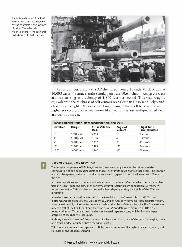
As for gun performance, a AP shell fired from a 12-inch Mark X gun at 10,000 yards (5 nautical miles) could penetrate 10.6 inches of Krupp concrete armour, striking at a velocity of 1,900 feet per second. This was roughly equivalent to the thickness of belt armour on a German Nassau or Helgoland-class dreadnought. Of course, at longer ranges the shell followed a much higher trajectory, and so was more likely to hit the less well-protected deck armour of a target.
Range and Penetration (given for armour-piercing shells)
Elevation Range Strike Velocity (fps)
Angle of Descent
Flight Time (approximate)
1° 1,500 yards 2,483 1° 2 seconds
3° 6,000 yards 1,884 4° 6 seconds
6° 10,000 yards 1,497 9° 15 seconds
12° 15,000 yards 1,179 20° 24 seconds
13.5° 18,500 yards 1,147 32° 31 seconds
HMS NEPTUNE, HMS HERCULES
The turret arrangement of HMS Neptune (top) was an attempt to alter the rather wasteful
configuration of earlier dreadnoughts so that all five turrets could fire to either beam. The solution
was less than perfect – the two middle turrets were staggered to permit a limited arc of fire across
the deck.
‘X’ turret was also raised up a deck and was superimposed over ‘Y’ turret, which permitted a clear
field of fire but led to the crew of the aftermost turret suffering from concussion every time ‘X’
turret opened fire. This problem was solved in later ships by raising the height of the ‘X’ turret
mounting.
A similar turret configuration was used in the two ships of the Colossus class. HMS Hercules
(bottom) and her sister Colossus were identical, and by necessity they also resembled the Neptune,
as to save time only minor variations were made to the plans of the earlier ship. The foremast was
moved abaft of the first funnel, and the wing turrets ‘P’ and ‘Q’ were mounted a little closer
together than on Neptune to permit a longer forward superstructure, which allowed a better
grouping of secondary 4-inch guns.
Both Neptune and the two Colossus-class ships kept their boats clear of the guns by carrying them
on a flying bridge mounted above the wing turrets.
This shows Neptune as she appeared in 1914, before her forward flying bridge was removed, and
Hercules as she looked at Jutland.
E
The fitting of a new 12-inch/45
Mark X gun barrel, watched by
civilian contractors and a crowd
of sailors. These barrels
weighed over 57 tons each and
had a bore of 43 feet 3 inches.
© Osprey Publishing • www.ospreypublishing.com

© Osprey Publishing • www.ospreypublishing.com

36
ProtectionWhile the dreadnought can be seen as a powerful and fast-moving naval gun battery, its effectiveness as a fighting unit involved maintaining its place in the line of battle. This meant three things – the ability to manoeuvre effectively, the power to engage smaller enemy vessels which threatened it, and the capacity both to absorb damage from enemy hits and to deal with any flooding or fire damage before it could reduce the ability of the ship to move and fight.
When action was imminent, the engine room staff would make sure that the propulsion system was working as effectively as possible and that they were ready to respond to any sudden demands for changes of speed or power. Damage control parties would stand by in readiness to repair any damage to fuel lines or steam pipes, to counter flooding, or to rig emergency power cables or lighting if required. However, there was little her crew could do to improve their chances of surviving a hit from an enemy shell; they had to rely on the armoured protection provided by the ship designers for that. They could play their part by maintaining good watertight
The armoured protection of the
Colossus-class dreadnoughts
represented an improvement
over the Neptune, but to save
weight protection was still
concentrated on the waterline
belt, the conning tower and
the turret barbettes.
In Dreadnought the armour
was concentrated along her
waterline belt, which was
thicker between her turrets
than it was closer to her bow
and stern. A similar degree of
protection was afforded to her
conning tower, turret facings
and barbettes.
© Osprey Publishing • www.ospreypublishing.com
37
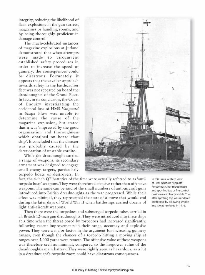
integrity, reducing the likelihood of flash explosions in the gun turrets, magazines or handling rooms, and by being thoroughly proficient in damage control.
The much-celebrated instances of magazine explosions at Jutland demonstrated that when attempts were made to circumvent established safety procedures in order to increase the speed of gunnery, the consequences could be disastrous. Fortunately, it appears that the cavalier approach towards safety in the battlecruiser fleet was not repeated on board the dreadnoughts of the Grand Fleet. In fact, in its conclusion, the Court of Enquiry investigating the accidental loss of HMS Vanguard in Scapa Flow was unable to determine the cause of the magazine explosion, but stated that it was ‘impressed by the good organisation and thoroughness which obtained on board that ship’. It concluded that the disaster was probably caused by the deterioration of unstable cordite.
While the dreadnought carried a range of weapons, its secondary armament was designed to engage small enemy targets, particularly torpedo boats or destroyers. In fact, the 4-inch QF batteries of the time were actually referred to as ‘anti-torpedo boat’ weapons. They were therefore defensive rather than offensive weapons. The same can be said of the small numbers of anti-aircraft guns introduced into British dreadnoughts as the war progressed. While their effect was minimal, they represented the start of a move that would end during the later days of World War II when battleships carried dozens of light anti-aircraft weapons.
Then there were the torpedoes and submerged torpedo tubes carried in all British 12-inch gun dreadnoughts. They were introduced into these ships at a time when the threat posed by torpedoes had increased significantly, following recent improvements in their range, accuracy and explosive power. They were a major factor in the argument for increasing gunnery ranges, even though the chances of a torpedo hitting a moving ship at ranges over 5,000 yards were remote. The offensive value of these weapons was therefore seen as minimal, compared to the firepower value of the dreadnought’s main battery. They were rightly seen as hazardous, as a hit in a dreadnought’s torpedo room could have disastrous consequences.
In this unusual stern view
of HMS Neptune lying off
Portsmouth, her tripod masts
and spotting top or fire control
positions are clearly visible. The
after spotting top was rendered
ineffective by billowing smoke
and it was removed in 1916.
© Osprey Publishing • www.ospreypublishing.com
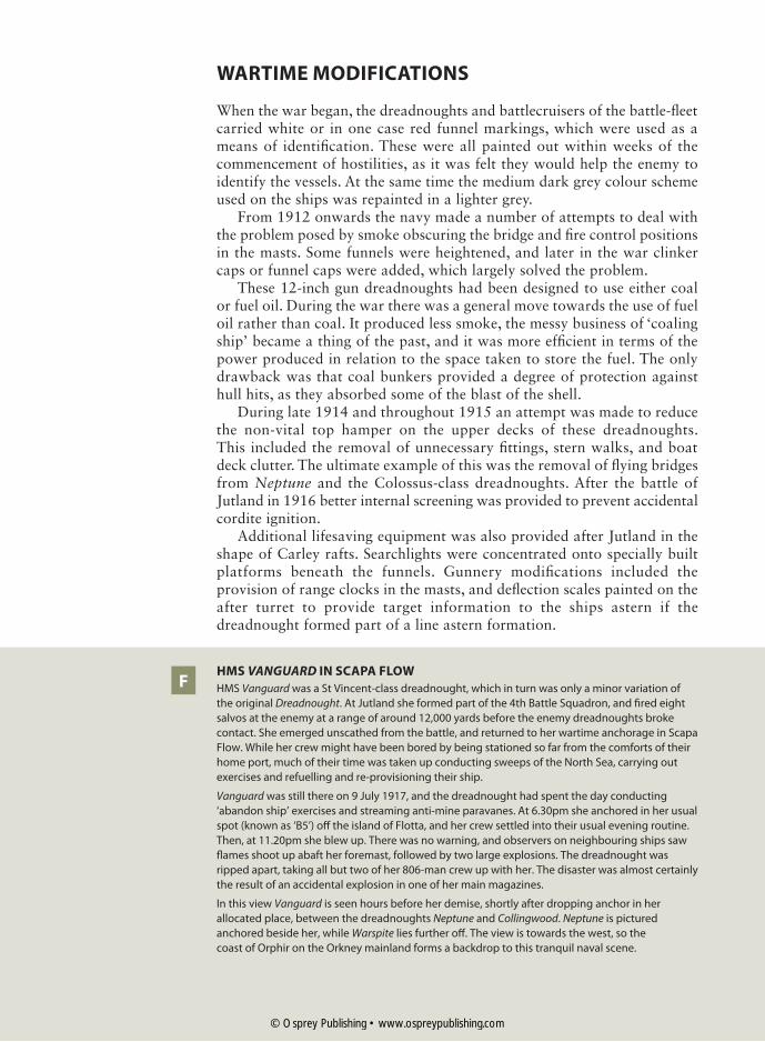
38
WARTIME MODIFICATIONS
When the war began, the dreadnoughts and battlecruisers of the battle-fleet carried white or in one case red funnel markings, which were used as a means of identification. These were all painted out within weeks of the commencement of hostilities, as it was felt they would help the enemy to identify the vessels. At the same time the medium dark grey colour scheme used on the ships was repainted in a lighter grey.
From 1912 onwards the navy made a number of attempts to deal with the problem posed by smoke obscuring the bridge and fire control positions in the masts. Some funnels were heightened, and later in the war clinker caps or funnel caps were added, which largely solved the problem.
These 12-inch gun dreadnoughts had been designed to use either coal or fuel oil. During the war there was a general move towards the use of fuel oil rather than coal. It produced less smoke, the messy business of ‘coaling ship’ became a thing of the past, and it was more efficient in terms of the power produced in relation to the space taken to store the fuel. The only drawback was that coal bunkers provided a degree of protection against hull hits, as they absorbed some of the blast of the shell.
During late 1914 and throughout 1915 an attempt was made to reduce the non-vital top hamper on the upper decks of these dreadnoughts. This included the removal of unnecessary fittings, stern walks, and boat deck clutter. The ultimate example of this was the removal of flying bridges from Neptune and the Colossus-class dreadnoughts. After the battle of Jutland in 1916 better internal screening was provided to prevent accidental cordite ignition.
Additional lifesaving equipment was also provided after Jutland in the shape of Carley rafts. Searchlights were concentrated onto specially built platforms beneath the funnels. Gunnery modifications included the provision of range clocks in the masts, and deflection scales painted on the after turret to provide target information to the ships astern if the dreadnought formed part of a line astern formation.
HMS VANGUARD IN SCAPA FLOW
HMS Vanguard was a St Vincent-class dreadnought, which in turn was only a minor variation of
the original Dreadnought. At Jutland she formed part of the 4th Battle Squadron, and fired eight
salvos at the enemy at a range of around 12,000 yards before the enemy dreadnoughts broke
contact. She emerged unscathed from the battle, and returned to her wartime anchorage in Scapa
Flow. While her crew might have been bored by being stationed so far from the comforts of their
home port, much of their time was taken up conducting sweeps of the North Sea, carrying out
exercises and refuelling and re-provisioning their ship.
Vanguard was still there on 9 July 1917, and the dreadnought had spent the day conducting
‘abandon ship’ exercises and streaming anti-mine paravanes. At 6.30pm she anchored in her usual
spot (known as ‘B5’) off the island of Flotta, and her crew settled into their usual evening routine.
Then, at 11.20pm she blew up. There was no warning, and observers on neighbouring ships saw
flames shoot up abaft her foremast, followed by two large explosions. The dreadnought was
ripped apart, taking all but two of her 806-man crew up with her. The disaster was almost certainly
the result of an accidental explosion in one of her main magazines.
In this view Vanguard is seen hours before her demise, shortly after dropping anchor in her
allocated place, between the dreadnoughts Neptune and Collingwood. Neptune is pictured
anchored beside her, while Warspite lies further off. The view is towards the west, so the
coast of Orphir on the Orkney mainland forms a backdrop to this tranquil naval scene.
F
© Osprey Publishing • www.ospreypublishing.com

39© Osprey Publishing • www.ospreypublishing.com
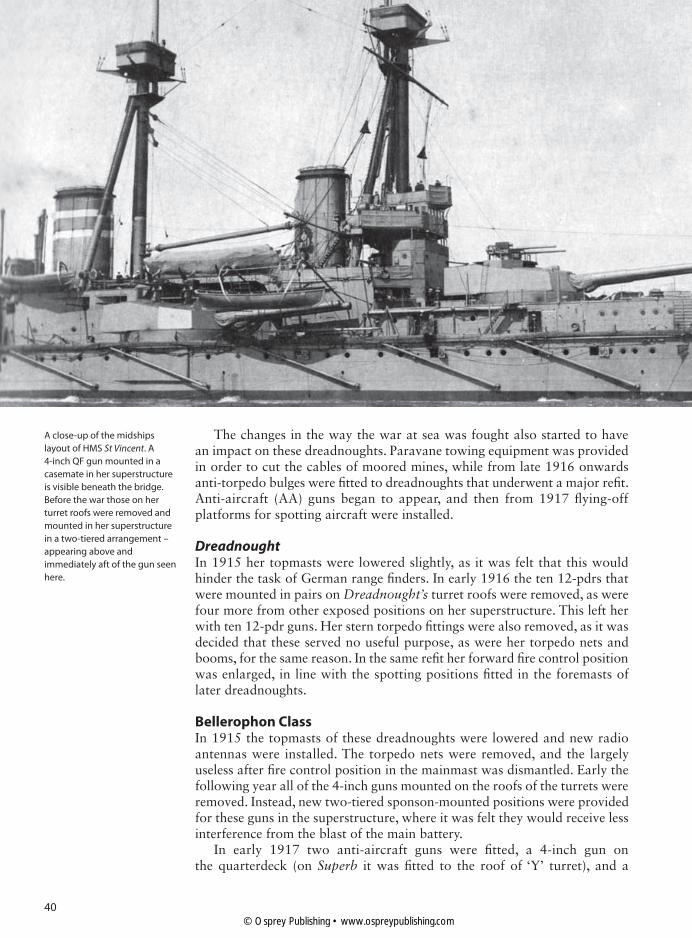
40
The changes in the way the war at sea was fought also started to have an impact on these dreadnoughts. Paravane towing equipment was provided in order to cut the cables of moored mines, while from late 1916 onwards anti-torpedo bulges were fitted to dreadnoughts that underwent a major refit. Anti-aircraft (AA) guns began to appear, and then from 1917 flying-off platforms for spotting aircraft were installed.
Dreadnought In 1915 her topmasts were lowered slightly, as it was felt that this would hinder the task of German range finders. In early 1916 the ten 12-pdrs that were mounted in pairs on Dreadnought’s turret roofs were removed, as were four more from other exposed positions on her superstructure. This left her with ten 12-pdr guns. Her stern torpedo fittings were also removed, as it was decided that these served no useful purpose, as were her torpedo nets and booms, for the same reason. In the same refit her forward fire control position was enlarged, in line with the spotting positions fitted in the foremasts of later dreadnoughts.
Bellerophon Class In 1915 the topmasts of these dreadnoughts were lowered and new radio antennas were installed. The torpedo nets were removed, and the largely useless after fire control position in the mainmast was dismantled. Early the following year all of the 4-inch guns mounted on the roofs of the turrets were removed. Instead, new two-tiered sponson-mounted positions were provided for these guns in the superstructure, where it was felt they would receive less interference from the blast of the main battery.
In early 1917 two anti-aircraft guns were fitted, a 4-inch gun on the quarterdeck (on Superb it was fitted to the roof of ‘Y’ turret), and a
A close-up of the midships
layout of HMS St Vincent. A
4-inch QF gun mounted in a
casemate in her superstructure
is visible beneath the bridge.
Before the war those on her
turret roofs were removed and
mounted in her superstructure
in a two-tiered arrangement –
appearing above and
immediately aft of the gun seen
here.
© Osprey Publishing • www.ospreypublishing.com

41
3-inch gun on the after superstructure. At the same time the stern torpedo fittings were removed, and a clinker screen (funnel cap) was added to the forward funnel, designed to direct smoke away from the open bridge and the fire control position. During the winter of 1917–18 all three dreadnoughts had been provided with ‘flying-off ramps’ built on top of their ‘A’ and ‘Y’ turrets, which were used by small aircraft – Sopwith Pups and Sopwith 1½ Strutters.
St Vincent Class Before the war the topmasts of these three dreadnoughts were lowered, and a pair of 4-inch guns mounted on the roofs of their ‘A’ turrets was removed. In the winter of 1915–16 two 3-inch AA guns were mounted on the quarterdeck. In early 1916 the vessels lost their torpedo nets, and in their post-Jutland refits in 1916–17 a clinker screen (funnel cap) was fitted to the fore funnel, to direct smoke away from the open bridge and the fire control position. On Collingwood a similar clinker screen was fitted to her after funnel. At the same time the stern torpedo fittings were removed, and the two smaller AA guns replaced by a single 4-inch AA gun. Other modifications made in late 1917 included the enlargement of the bridge and fire control positions of St Vincent and Collingwood, and the redistribution of the 4-inch guns into two tiered sponson positions, of the kind introduced into the ships of the Bellerophon class. Finally, the searchlights were also redistributed and mounted on small searchlight towers to improve their sweep closer to the hull of the ships.
In early 1917 Collingwood was fitted with flying-off platforms for aircraft over her fore and aft turrets, and by 1918 these were used to operate the two Sopwith aircraft used by the Bellerophon-class dreadnoughts.
Neptune Before the war Neptune’s fore funnel was heightened in an attempt to reduce the problem caused by smoke billowing around the bridge and the fire control position. The 4-inch guns mounted on top of her turrets were also moved into new sponson mounts located in her superstructure. Light steel screens were used to shield them from the blast of the main guns. Her searchlights were grouped together around and below the bridge. In late 1914 the forward flying bridge was removed, as it was liable to damage from the main battery, and wreckage might then hamper the turret. The after flying bridge was retained throughout the war.
The Grand Fleet lying at anchor
in Scapa Flow during the winter
of 1915–16. In the foreground
is Neptune, showing how she
looked after her forward flying
bridge was removed. Scapa
provided a secure deep-water
anchorage for Jellicoe’s
battle-fleet.
© Osprey Publishing • www.ospreypublishing.com

42
In 1915 the stern torpedo fittings were removed. In late 1916, Neptune had a clinker screen fitted to her forward funnel, and her twin searchlight mountings were replaced by single ones. During this refit her after fire control position was removed.
Colossus ClassIn 1912 the fore funnel was raised on these two dreadnoughts, in a successful attempt to solve the problems caused by billowing smoke. At the same time added protection was provided to the secondary battery positions. In Hercules this took the form of small gun shields, while on Colossus her guns were protected by drop-down mantlets. The redundant torpedo nets were lost during the winter of 1915–16. During their refits of 1917 these two dreadnoughts had their after flying decks removed, and three 4-inch guns were replaced by two AA weapons – a 4-inch and a 3-inch weapon, mounted on the quarterdeck and after superstructure respectively.
Agincourt Before Agincourt entered service with the Royal Navy she underwent modification – the most significant part of which was the removal of her large flying bridge. In 1916 her tripod mainmast was removed, and the main topmast placed on top of the large derrick post that stood between her funnels. During 1918 her cramped bridge was enlarged, and her searchlights were grouped together amidships.
HMS AGINCOURT
HMS Agincourt was one of a kind, and the largest 12-inch dreadnought in the Grand Fleet. She was
built for the Brazilian navy as an answer to the building of two Argentine dreadnoughts. Brazil
could ill afford her, however, and so while she was still under construction on Tyneside she was
sold to Turkey. She was completed in August 1914, but Britain delayed her delivery until Turkey’s
stance in the war became clear. When Turkey allied herself with Germany the vessel was seized,
and she was duly commissioned into the Royal Navy as HMS Agincourt.
She carried no fewer than seven turrets, and unlike other dreadnoughts these were given
numerical labels, from ‘1’ to ‘7’. Inevitably the crew unofficially labelled them after the days of the
week, so ‘1’ (or ‘A’ turret) became ‘Monday’. Critics labelled her a floating ‘gin palace’, but she
proved her worth at Jutland, firing ten salvos at the enemy during the battle.
Her turrets were mounted along her centreline, as shown in the plan view, with ‘3’ and ‘4’ turrets
mounted back to back and ‘5’ facing forward with its back to ‘6’ turret. ‘2’ and ‘6’ turrets were
superimposed, which allowed them to fire over the turrets in front of them. She was an impressive
warship, and eyewitnesses at Jutland described how the firing of her full broadside produced an
enormous sheet of flame that resembled a ship blowing up.
G
Although HMS Agincourt was
viewed with suspicion in some
quarters due to her relatively
light armour and her non-
standard guns, the ‘Gin Palace’
proved her worth at Jutland.
This view of Agincourt shows
her after her mainmast was
removed and its topmast
placed on top of the derrick
post.
© Osprey Publishing • www.ospreypublishing.com

43© Osprey Publishing • www.ospreypublishing.com
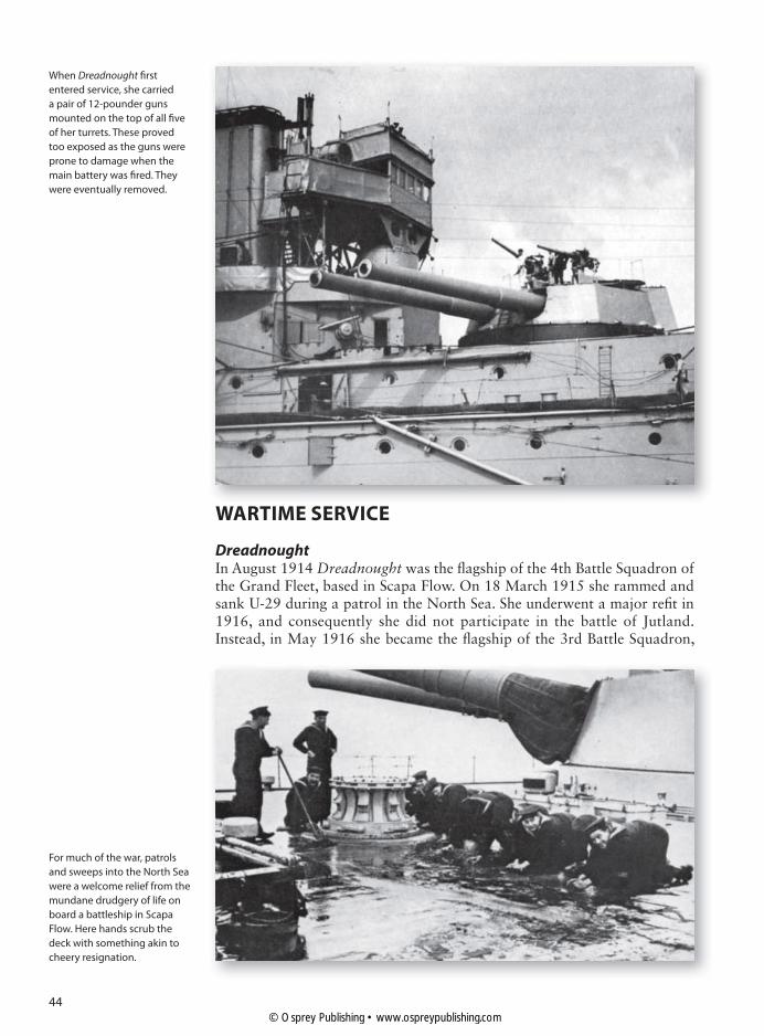
44
WARTIME SERVICE
Dreadnought In August 1914 Dreadnought was the flagship of the 4th Battle Squadron of the Grand Fleet, based in Scapa Flow. On 18 March 1915 she rammed and sank U-29 during a patrol in the North Sea. She underwent a major refit in 1916, and consequently she did not participate in the battle of Jutland. Instead, in May 1916 she became the flagship of the 3rd Battle Squadron,
When Dreadnought first
entered service, she carried
a pair of 12-pounder guns
mounted on the top of all five
of her turrets. These proved
too exposed as the guns were
prone to damage when the
main battery was fired. They
were eventually removed.
For much of the war, patrols
and sweeps into the North Sea
were a welcome relief from the
mundane drudgery of life on
board a battleship in Scapa
Flow. Here hands scrub the
deck with something akin to
cheery resignation.
© Osprey Publishing • www.ospreypublishing.com

45
a force consisting of King Edward VII-class pre-dreadnoughts, based in Sheerness. She rejoined the 4th Battle Squadron of the Grand Fleet in March 1918, and resumed her role as squadron flagship. Dreadnought was paid off in July 1918, and in February 1919 she was placed in reserve.
Bellerophon ClassIn early August 1914 Bellerophon was serving with the 1st Battle Squadron when she was in a collision with a merchantman. After minor repairs she joined the newly formed 4th Battle Squadron of the Grand Fleet, based in Scapa Flow. She formed part of this squadron at Jutland, as did Temeraire. Superb was transferred from the 1st to the 3rd Battle Squadron in January 1915, and in May 1916 she replaced Dreadnought as the squadron flagship. All three dreadnoughts took part in the battle of Jutland on 31 May 1916. In October 1918 Superb and Temeraire were sent to the Mediterranean, and the following month Superb led the Allied fleet through the Dardanelles. All three dreadnoughts were placed in reserve in 1919, Bellerophon and Superb becoming turret drill ships while Temeraire became a training ship for naval cadets.
St Vincent ClassIn August 1914, Collingwood, St Vincent and Vanguard all formed part of the 1st Battle Squadron, based in Scapa Flow. St Vincent became the flagship of the squadron’s rear admiral, who commanded its 2nd Division. All three battleships participated in the battle of Jutland. In July they were all transferred to the 4th Battle Squadron, and Collingwood and St Vincent remained in the squadron until the end of the war. Vanguard was destroyed on 9 July 1917 as a result of an accidental magazine explosion while she lay at anchor in Scapa Flow. The two surviving dreadnoughts of the class were placed in reserve in 1919 and became gunnery training ships.
Neptune In August 1914 Neptune formed part of the 1st Battle Squadron, based in Scapa Flow. She remained with the squadron until after the battle of Jutland.
HMS Colossus at anchor in
Scapa Flow in late 1917.
Both of the Colossus-class
dreadnoughts had the after
flying bridge removed in early
1917. Colossus was the only
British dreadnought battleship
to be damaged at Jutland,
receiving two hits in her
forward superstructure from
the German battlecruiser
Seydlitz.
© Osprey Publishing • www.ospreypublishing.com
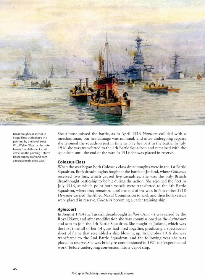
46
She almost missed the battle, as in April 1916 Neptune collided with a merchantman, but her damage was minimal, and after undergoing repairs she rejoined the squadron just in time to play her part in the battle. In July 1916 she was transferred to the 4th Battle Squadron and remained with the squadron until the end of the war. In 1919 she was placed in reserve.
Colossus ClassWhen the war began both Colossus-class dreadnoughts were in the 1st Battle Squadron. Both dreadnoughts fought at the battle of Jutland, where Colossus received two hits, which caused five casualties. She was the only British dreadnought battleship to be hit during the action. She rejoined the fleet in July 1916, at which point both vessels were transferred to the 4th Battle Squadron, where they remained until the end of the war. In November 1918 Hercules carried the Allied Naval Commission to Kiel, and then both vessels were placed in reserve, Colossus becoming a cadet training ship.
Agincourt In August 1914 the Turkish dreadnought Sultan Osman I was seized by the Royal Navy, and after modification she was commissioned as the Agincourt and sent to join the 4th Battle Squadron. She fought at Jutland, which was the first time all of her 14 guns had fired together, producing a spectacular sheet of flame that resembled a ship blowing up. In October 1918 she was transferred to the 2nd Battle Squadron, and the following year she was placed in reserve. She was briefly re-commissioned in 1921 for ‘experimental work’ before undergoing conversion into a depot ship.
Dreadnoughts at anchor in
Scapa Flow, as depicted in a
painting by the naval artist
W. L. Wyllie. Of particular note
here is the plethora of small
vessels in the painting – ships’
boats, supply craft and even
a recreational sailing yawl.
© Osprey Publishing • www.ospreypublishing.com

47
BIBLIOGRAPHY
Archibald, E. H. H., The Fighting Ship in the Royal Navy, AD897–1984, Blandford Press (Poole, 1987)
Brown, David K., The Grand Fleet: Warship Design and Development, 1906–1922, Seaforth Publishing (Barnsley, 1997)
Brown, David K., Warrior to Dreadnought: Warship Design and Development, 1860–1905, Seaforth Publishing (Barnsley, 2010)
Burt, R. A., British Battleships of World War One, Seaforth Publishing (Barnsley, 2012)
Campbell, John, Jutland: An Analysis of the Fighting, Conway Maritime Press (London, 1986)
Friedman, Norman, Battleship Design and Development, 1905–1945, Smithmark Publishing (New York, NY, 1979)
Gardiner, Robert (ed.), Conway’s All the World’s Fighting Ships, 1906–1921, Conway Maritime Press (London, 1985)
Gardiner, Robert, The Eclipse of the Big Gun: The Warship 1906–45, Conway Maritime Press History of the Ship Series (London, 1992)
Hodges, Peter, The Big Gun: Battleship Main Armament, 1860–1945, Conway Maritime Press (London, 1981)
Howarth, David, The Dreadnoughts, Time-Life Books (Alexandria, VA, 1980)Le Fleming, H. M., Warships of World War I (1): Battleships, Ian Allen
(London, 1961)Marder, Arthur J., From the Dreadnought to Scapa Flow, 5 volumes,
Oxford University Press (Oxford, 1966)Massie, Robert K., Dreadnought: Britain, Germany and the Coming of the Great
War, Random House (London, 1993)Moore, John, Jane’s Fighting Ships of World War I, Studio Editions (1990)Padfield, Peter, Guns at Sea, Hugh Evelyn Ltd. (London, 1973)Parkes, Oscar, British Battleships, 1860–1950, Seeley Services & Co.
(London, 1973)Pears, Randolph, British Battleships, 1892–1957: The Great Days of the Fleets,
Randolph Pears (London, 1957)Thomas, Roger D., and Patterson, Brian, Dreadnoughts in Camera, 1905–1920,
Sutton Publishing (Stroud, 1998)
© Osprey Publishing • www.ospreypublishing.com
48
INDEXNumbers in bold refer to illustrations.
Agamemnon, HMS 7Agincourt, HMS 14, 23–24, 23, 24,
33, 42–43 specifications 29 wartime modifications 42 wartime service 46Argentina 21, 23–24Asquith, Herbert 14
Bacon, Captain Reginald 13Bannerman-Campbell, Henry 13–14Bellerophon, HMS 14–15, 17, 17, 45Bellerophon class 7, 10, 16–17, 33 specifications 25 wartime modifications 40–41 wartime service 45Brazil 21, 23–24
Churchill, Winston 24coaling ships 9, 10Collingwood, HMS 18–19, 45Colossus, HMS 23, 42, 46Colossus class 21, 22–23, 33, 36 specifications 29 wartime modifications 38, 42 wartime service 46Committee on Designs 8–9
Deadman, Henry 8design and development 5–24 Agincourt see Agincourt, HMS Bellerophon class see
Bellerophon class the big gun battleship 7–9, 13 Colossus class see Colossus class Dreadnought see Dreadnought,
HMS gunnery fire control see fire control Neptune see Neptune, HMS new features 5 pre-dreadnoughts see
pre-dreadnoughts rebuilding the fleet 13–14 St Vincent class see St Vincent class steam turbines for propulsion 4, 5,
8, 10, 12Director of Naval Construction (DNC)
see Watts, Sir PhilipDreadnought, HMS 4–5, 7, 9–13,
10–11, 12, 16–17, 26–27 armaments 5, 9–10, 20, 29, 33, 44 armour 12, 36 design and construction 8–9 defects/criticisms 13, 20 officer accommodation under
bridge 12–13 propulsion and speed 12, 13 era of naval history named after
4, 10–11
largest/most powerful warship in world 4, 6, 9, 10
launched 4, 9, 13, 14 specifications 25 wartime modifications 40 wartime service 44–45dreadnoughts armaments 5, 9–10, 20, 21, 23, 24,
29–30, 32, 33, 37 homogenous main armament
5, 10, 29 lacking secondary armaments
7, 10 main battery 33–34 building programme 4–5, 6 design and development
see design and development other countries building 5, 14, 17 ‘super dreadnoughts’ 21, 23Durston, Chief Sir John 8
fighting potential 29–37 fire control see fire control main battery 33–34 protection 36–37fire control 5, 10, 10, 30–33 Barr and Stroud coincidence
rangefinder 30, 31 Dreyer Fire Control Table 31–32, 31Fisher, Admiral Sir John 4, 7–10, 12,
13, 14, 16, 17, 33
Germany dreadnoughts 20, 30, 34 building 5, 14, 17
Helgoland class (Germany) 30, 34Hercules, HMS 22, 23, 34–35, 46 wartime modifications 42Hibernia, HMS 5Hood, HMS 6, 13Hood, Sir Arthur 6
Italy: ship-building 8
Japan: dreadnought/ship-building 8, 17
Jellicoe, Admiral Sir John 14, 16, 41Jutland, battle of (1916) 7, 10, 14–15,
37, 38, 42, 44,-46
Krupp armour 6, 12, 34
Liberal Government 13–14, 22Lloyd George, D. 14 Lord Nelson, HMS 7
Michigan, USS 8
Narbeth, John 8Nassau class (Germany) 20, 34
Neptune, HMS 20–22, 20, 21, 23, 32, 33, 34–35, 37, 38–39, 41
specifications 28 wartime modifications 38, 41–42 wartime service 45–46
Oldenburg, SMS 30Orion class 13
pre-dreadnoughts 4, 5–7, 10, 13 Bellerophon class
see Bellerophon class Canopus class 6 Duncan class 6 Formidable class 6 King Edward VII class 5, 6–7, 45 London class 6 Lord Nelson class 7, 8, 9, 33 Majestic class 6 Royal Sovereign class 6 semi-dreadnought battleships 7
Royal Navy 14 Grand Fleet 5, 14, 23, 24, 37,
41, 44–45 largest fleet in the world 4 programme of ship construction
4–5, 13–14
Scott, Captain Sir Percy 29specifications 25–29St Vincent, HMS 40, 45St Vincent class 8, 17–20, 33 specifications 28 wartime modifications 41 wartime service 45South Carolina, USS 8South Carolina class (US) 20Sultan Osman I see Agincourt, HMSSuperb, HMS 14, 16, 17, 40, 45
Temeraire, HMS 7, 10–11, 14, 16, 17, 45
Tirpitz, Admiral 14Tsushima, battle of (1905) 7Turkey 24
United States (US) 24 dreadnought/ship-building 8, 17
Vanguard, HMS 17, 18, 28, 38–39, 45
loss of in Scapa Flow 37, 38
wartime modifications 38–43Watts, Sir Philip 4, 5, 7–10, 16,
20–21, 23White, Sir William 6, 7World War I (1914–18) 8, 24 blamed partly on British/German
shipbuilding race 5, 14
© Osprey Publishing • www.ospreypublishing.com

Related Titles - New Vanguard Series
epub ISBN PDF ISBN No. TITLE
9781782006947 9781846037467 16 Leopard 1 Main Battle Tank 1965–95
9781782006954 9781846037443 24 Leopard 2 Main Battle Tank 1979–98
9781782002253 9781782002512 43 Siege Weapons of the Far East (1)
9781782002260 9781782002529 44 Siege Weapons of the Far East (2)
9781472800619 9781472800954 49 Mississippi River Gunboats of the AmericanCivil War 1861–65
9781782004219 9781782004714 53 M8 Greyhound Light Armored Car 1941–91
9781782008392 9781782009054 56 Union River Ironclad 1861–65
9781782002376 9781782002635 57 M10 and M36 Tank Destroyers 1942–53
9781782005223 9781782005605 79 American Heavy Frigates 1794–1826
9781782004325 9781782004752 80 Chieftain Main Battle Tank 1965–2003
9781782004349 9781782004776 85 M60 Main Battle Tank 1960–91
9781782004301 9781782004745 94 British Artillery 1914–19
9781472801647 9781472802262 95 Armored Units of the Russian Civil War
9781782004189 9781782004707 99 Space Shuttle Launch System 1972–2004
9781782002130 9781782002048 107 US Anti-tank Artillery 1941–45
9781782004585 9781782004899 115 Landing Ship, Tank (LST) 1942–2002
9781782004592 9781782004908 121 Stryker Combat Vehicles
9781472801760 9781472802347 127 German Panzers 1914–18
9781472800343 9781472800756 129 British Submarines 1939–45
9781472800350 9781846038594 145 British Submarines of World War I
9781782008408 9781846038808 154 British Battleships 1939–45 (1)
9781472800664 9781846038952 155 British Airships 1905–30
9781782008415 9781849080804 168 British Aircraft Carriers 1939–45
9781782001416 9781846039546 171 Mil Mi-24 Hind Gunship
9781782008705 9781849083119 177 Humber Light Reconnaissance Car 1941–45
9781782008422 9781849084093 181 Yangtze River Gunboats 1900–49
9781780960401 9781849085632 187 Imperial Japanese Navy Light Cruisers 1941–45
9781780968773 9781849086370 192 US Amphibious Tanks of World War II
9781780968971 9781849086899 193 Austro-Hungarian Battleships 1914–18
9781782003076 9781849086875 194 British Light Cruisers 1939–45
9781780961231 9781849087766 195 Italian Medium Tanks
9781849089791 9781849089807 196 Warships of the Ancient World
OSPREYP U B L I S H I N G
© Osprey Publishing • www.ospreypublishing.com

First published in Great Britain in 2013 by Osprey Publishing,Midland House, West Way, Botley, Oxford, OX2 0PH, UK43-01 21st Street, Suite 220B, Long Island City, NY 11101, USAE-mail: [email protected] Osprey Publishing is part of the Osprey Group © 2013 Osprey Publishing Ltd. All rights reserved. Apart from any fair dealing for the purpose of private study, research, criticism or review, as permitted under the Copyright, Designs and Patents Act, 1988, no part of this publication may be reproduced, stored in a retrieval system, or transmitted in any form or by any means, electronic, electrical, chemical, mechanical, optical, photocopying, recording or otherwise, without the prior written permission of the copyright owner. Enquiries should be addressed to the Publishers. A CIP catalogue record for this book is available from the British Library Print ISBN: 978 1 78096 167 5PDF e-book ISBN: 978 1 78096 168 2EPUB e-book ISBN: 978 1 78096 169 9 Index by Judy OliverTypeset in Sabon and Myriad ProOriginated by PDQ Media, Bungay, UKPrinted in China through Worldprint Ltd. 13 14 15 16 17 10 9 8 7 6 5 4 3 2 1 www.ospreypublishing.com
Osprey Publishing is supporting the Woodland Trust, the UK’s leading woodland conservation charity, by funding the dedication of trees.
© Osprey Publishing. Access to this book is not digitally restricted. In return, we ask you that you use it for personal, non-commercial purposes only. Please don’t upload this ebook to a peer-to-peer site, email it to everyone you know, or resell it. Osprey Publishing reserves all rights to its digital content and no part of these products may be copied, stored in a retrieval system or transmitted in any form by any means, electronic, mechanical, recording or otherwise (except as permitted here), without the written permission of the publisher. Please support our continuing book publishing programme by using this e-book responsibly.
Every effort has been made by the Publisher to secure permissions to use the images in this publication. If there has been any oversight we would be happy to rectify the situation and written submission should be made to Osprey Publishing.
© Osprey Publishing • www.ospreypublishing.com