Brief description - LAS A&S
24
Brief description wir sind sicherheit.
Transcript of Brief description - LAS A&S

Brief description
wir sind sicherheit.


Brief description Date: 2017.08.15 Page 3 of 24
The direct way to safe automation

Contents
Brief description Date: 2017.08.15 Page 4 of 24
1 SL VARO Modules ............................................................................................................................................................................. 5
2 Intended purpose ............................................................................................................................................................................. 5
2.1 Certification data .............................................................................................................................................................................. 5
3 Product description ......................................................................................................................................................................... 6
3.1 Mounting ............................................................................................................................................................................................. 7
3.2 Terminals ............................................................................................................................................................................................. 7
4 Central modules ................................................................................................................................................................................ 8
5 Standstill and speed monitoring................................................................................................................................................ 10
5.1 DNCO function to monitor the Peripheral speed ................................................................................................................ 11
5.2 DNCO1 connection schematic................................................................................................................................................... 11
6 Cable adapter DNDA ..................................................................................................................................................................... 11
7 In-, output modules ........................................................................................................................................................................ 12
8 Feild bus modules ........................................................................................................................................................................... 13
9 Cascade module DNSL-CMV ...................................................................................................................................................... 14
10 Network module DNSL-NIV ........................................................................................................................................................ 15
11 Network Module DNSL-NRV ....................................................................................................................................................... 16
12 Terminals for safety functions.................................................................................................................................................... 17
12.1 Analogue inputs at the central module ................................................................................................................................... 17
12.2 Inputs for function mode selection switch (FMSS) at central module ......................................................................... 17
12.3 Inputs for Tow-Hand function according EN 574: Type IIIC .............................................................................................. 17
12.4 Inputs for shut down mats, switch rails and bumpers at central module .................................................................... 18
12.5 Important notes with using of shutdown mats, switch rails and bumpers ................................................................. 18
12.1 Inputs for Safety circuits (SC) with manual Quit .................................................................................................................. 19
12.2 Inputs for Safety circuits (SC) with Quit via Q ....................................................................................................................... 19
12.3 Inputs for Safety circuits (SC) without Quit ........................................................................................................................... 19
13 Outputs at SL VARIO .................................................................................................................................................................... 20
14 General technical data ................................................................................................................................................................. 21
14.1 Electrical characteristics ............................................................................................................................................................. 21
14.2 Environment conditions ............................................................................................................................................................... 21
14.3 Technical data of the Semiconductor outputs ..................................................................................................................... 21
Technical data Semiconductor outputs .............................................................................................................................................. 21
14.4 Technical data of the contact outputs ................................................................................................................................... 22
14.5 Electrical life of the contact outputs ...................................................................................................................................... 22
15 Dimensions ...................................................................................................................................................................................... 23
15.1 Fitting and remove ........................................................................................................................................................................ 23

SL VARO Modules
Brief description Date: 2017.08.15 Page 5 of 24
1 SL VARO Modules
Central modules Speed Monitoring In- output modules Network modules Field bus modules Cascade modules
DNSL-ZMV DNSL-ZMVA DNSL-ZMVD DNSL-ZMVK
DNSL-DSV DNSL-DSIV DNSL-DRV DNSL-SIV
DNSL-INV DNSL-IOV DNSL-RMV
DNSL-NIV DNSL-NRV
DNSL-COV DNSL-DPV DNSL-ECV DNSL-EPV DNSL-MOV DNSL-PLV DNSL-PNV
DNSL-CMV
2 Intended purpose
Testing based on: EN 55011: 2009+A1 2010 (class A), DIN EN 61326-1: 2013-07, EN 61000-6-2: 2016-05, EN 61326-3-1: 2015-06, EN 61000-4-11: 2005-02
• DIN EN 60947-5-1: 2015-05 Low-voltage switch gear, part 5.1: Control circuit devises and switching elements-electromechanical control circuit devices
• DIN EN ISO 13849-1: 2016-06 Safety-related parts of control systems; Part 1: General principles for design category 4, PLe
• DIN EN ISO 13849-2: 2013-02
Safety-related parts of control systems; Part 2: Validation
• DIN EN 62061: 2016-05
Functional safety of safety-related electrical, electronic and programmable electronic control systems SIL CL3
• DIN EN 574, type IIC, two-hand control devices, DNSL-SIV type IIIB
• DIN EN ISO 13856-1:2013-08 / -2:2013-08 / -3:2013-12, for signal processing only
• GS-ET-20: 2016-10, basic principles for testing and certification of safety switch devices
Authorized person for the combination of the technical documents: Dirar Najib, CEO Esslinger Str. 84, D 72649 Wolfschlugen, Wolfschlugen, 2017-07-27
2.1 Certification data
Modul MTTFd PL DC SFF PFHd
TM: 20 years
DNSL-ZMV 79 years E high 99% 3.0 x 10⁻⁸
DNSL-ZMVK 141 years E high 99% 1.6 x 10⁻⁸
DNSL-DSV 97 J years E high 96% 2.5 x 10⁻⁸
DNSL-DRV 97 years E high 96% 2.5 x 10⁻⁸
DNSL-SIV 165 years D high 95% 3.3 x 10⁻⁸
DNSL-INV 238 years E high 95% 1.4 x 10⁻⁸
DNSL-IOV 97 years E high 96% 2.5 x 10⁻⁸
DNSL-RMV 91 years E high 98% 2.5 x 10⁻⁸
DNSL-CMV 91 years E high 98% 2.5 x 10⁻⁸
DNSL-NIV 214 years D high 95% 1.1 x 10⁻⁸
DNSL-DPV 305 years E high 95% 8.0 x 10⁻⁹
DNSL-ECV 305 years E high 95% 8.0 x 10⁻⁹
DNSL-COV 305 years E high 95% 8.0 x 10⁻⁹
Product is evaluated as safety device according:
• DIN EN ISO 13849-1: 2008-12, category 4, Ple, DIN EN 62061: 2005-10, SIL CL 3
• Certificated by: (Fachausschuss für Elektrotechnik, Prüf- und Zertifizierungsstelle Köln), European notified institution, Identification-number 0340 EC-Type Test certificate (DGUV Test: ET 13032 from 13-05-2013)
• EMC-directive certificated by “ELMAC GmbH Bondorf”, Reg. No.: DAT-P-206/05-00
• CNL, USL: File E227037
• QM System certificated according to DIN EN ISO 9001:2015 by “DQS, Frankfurt”, Reg.-No.: 067542 QM 08
• Certificate and declaration of conformity: See www.dina.de, download
R
1ZD7
US LISTEDIND.CONT.EQ

Product description
Brief description Date: 2017.08.15 Page 6 of 24
3 Product description
• SL VARIO is a multi-functional, modular and configurable safety system.
• The system consists of a central module and different function- and field bus modules.
• The field bus enables a communication between SL VARIO and the field bus master.
• The product is appropriated to be used in machines and automation to avoid dangers.
• The central module is available in 45 or 67.5 mm housing depending on the quantity of outputs.
All other modules are in 22.5 mm housing.
• Mounting happens on a 35 mm standard rail.
• The modules are connected directly to the ground via the standard rail.
• The modules are plugged together via a bus connector at the rail side. The bus is on 2 channels.
• Up to 15 modules can be used in one application.
• Modules with different functions are available.
• A variety of functions are available such as speed monitoring, logic modules, timers, safety circuits, mode
selector, generator, counters, comparators, feedback, restart interlock functions.
• A lot of safe digital and analogue inputs, safe semiconductor and contact outputs are available.
• The status of inputs, outputs, power supply and diagnostic functions is displayed via LED.
• Online and rack diagnostic are available via the Designer.
• An application can be simulated without hardware.
• Overvoltage and overcurrent are monitored.
Voltage ≥30V or not connected terminal (A2) disconnects internally the terminals (A1) and (P).
• Semiconductor outputs are overload and short-circuit-proof.
• An internal temperature sensor for diagnostic function via the Designer is available in all modules.
• The user´s application will be developed through the Designer. The data transfer happens via the USB
interface at the central module.
• The Designer is software developed by DINA.
• A memory chip is installed inside the central module. Documents as application software, Designer and
instruction manuals can be transferred to the memory using the USB interface.
• The memory chip can be used as a drive.
Remark
The function devices are tested safe and certificated as a part of the firmware.
A modification of the certified function devices as part of the firmware is excluded.

Product description
Brief description Date: 2017.08.15 Page 7 of 24
3.1 Mounting
• The central module is placed on the left side. All other modules must be added to the right side.
• For an application a central module is necessary.
• The number of the functional modules depends on the requirements.
• The plugs for measurement systems at the speed monitoring and for the data interface at the network and
cascade module are on the top side of the module after mounting.
• RJ45 plugs are also at the bottom side of DNSL-ZMD and DNSL-NRV for speed monitoring and network. They are to use for description function only.
• The connecting cable can be fed directly into the cable channel.
• The field bus connector is at the front side.
Central module Speed monitoring In-, output modules EtherCAT
DNSL-ZMVK DNSL-DSIV DNSL-DRV DNSL-INV DNSL-IOV DNSL-RMV Bus DNSL-ECV
3.2 Terminals
Die Module sind Standard mit Einzelklemmen bestückt.
Entriegelung oberhalb der Klemme
Alle Module sind mit Doppelklemmen erhältlich.
Entriegelung: oben oder zwischen den Klemmen
1 2 3 4
1 2 3 4

Central modules
Brief description Date: 2017.08.15 Page 8 of 24
4 Central modules
DNSL-ZMV DNSL-ZMVA DNSL-ZMVK
DNSL-ZMVD

Central modules
Brief description Date: 2017.08.15 Page 9 of 24
DNSL-ZMV
• eight safe analogue-digital inputs for safety functions
• eight safe digital inputs for safety functions
• four digital inputs or safe semi-conductor outputs
• six safe semi-conductor outputs
• two safe contact outputs
• two safe monitoring of standstill and speed via sensor with 24V signals in different operating modes and
one safe monitoring of standstill, speed, position, direction and brake in different operating modes, HTL measuring system or
• two safe monitoring of standstill, speed, position, direction and brake in different operating modes,
HTL measuring system
DNSL-ZMVA
• as DNSL-ZMV added
• four analogue outputs 4 to 20mA
• four analogue outputs 0 to 10V
DNSL-ZMVD (44ZM01)
• as DNSL-ZMV added
• four safe monitoring of standstill, speed, position, direction and brake in different operating modes
Sin/ Cos or TTL measuring system, HTL measuring system using HTL-cable adapter
• 16 safe digital inputs for safety functions
DNSL-ZMVD (48ZM01)
• as DNSL-ZMV added
• eight safe monitoring of standstill, speed, position, direction and brake in different operating modes
Sin/ Cos or TTL measuring system, HTL measuring system using HTL-cable adapter
• 32 safe digital inputs for safety functions
•
DNSL-ZMVK
• as DNSL-ZMV added
• four Relay outputs every with 2 safe contacts
Power supply (24 VDC) is to connect to A1/ A2 terminals for the central module and the other modules in the application

Standstill and speed monitoring
Brief description Date: 2017.08.15 Page 10 of 24
5 Standstill and speed monitoring
DNSL-DSV DNSL-DSV2 DNSL-DSIV DNSL-DRV DNSL-SIV obere Seite
DNSL-DSV
• eight safe digital inputs for safety functions
• five safe semi-conductor outputs and 2 switch outputs
• two safe monitoring of standstill, speed, position, direction and brake in different operating modes Sin/ Cos or TTL measuring systems, HTL measuring system using HTL-cable adapter
DNSL-DSV2
• as DNSL-DSV but seven safe semi-conductor outputs
DNSL-DSIV
• eight safe digital inputs for safety functions
• seven safe semi-conductor outputs
• one safe monitoring of standstill, speed, position, direction and brake in different operating modes
Sin/ Cos or TTL measuring system, HTL measuring system using HTL-cable adapter
• one safe monitoring of standstill, speed, position, direction and brake in different operating modes
SSI interface measuring system
• comparator function to compare both monitoring
DNSL-DRV
• as DNSL-DSV but for Resolver measuring systems
DNSL-SIV
• eight safe digital inputs for safety functions
• four safe semi-conductor outputs
• two safe monitoring of standstill, speed, position, direction and brake in different operating modes
SSI interface measuring system
Power supply (24 VDC) for the semi-conductor outputs is to connect to P terminal

Cable adapter DNDA
Brief description Date: 2017.08.15 Page 11 of 24
5.1 DNCO function to monitor the Peripheral speed
16 monitored speeds 64 monitored speeds
I1 I2 I3 I4 I1 I2 I3 I4 I5 I6
• The DNCO function by DNSL-DSV, DRV and ZMV enables the monitoring of the peripheral speeds of machined parts or tools.
• 16 different speeds for two monitoring and for every operating mode or
• 64 different speeds for two monitoring during the automatic mode.
• The speeds can be entered in two frequency tables at the Designer.
• The selection of the monitored speeds happens via the bit code wiring of the terminal inputs.
• 4 inputs enable to monitor 16 speeds in all operating modes. For up to 64 speeds 6 terminal inputs are
required.
• The DNCO1 unit can be used to set these inputs.
DNCO1 5.2 DNCO1 connection schematic
DNCO1
TK
DNSL-DSVDNSL-DRVDNSL-ZMV
D1
D2
D3
D4
D5
D6
I1
I2
I3
I4
I1
I2
I3
I4I5
I616/64
6 Cable adapter DNDA
The DNDA is used as an interconnection between the measuring system of the axle and the speed monitoring system. It is available for all CNC variations. See instruction manual „Cable adapter“.
DNDA 9/8 DNDA 15/8 DNDA 25/8
DNRJ45-HTL-SL is to use with incremental Measuring system with HTL-signals
DNRJ45 HTL-SL Wire colours
ID-No.: 95RJ20
: 0V
: A
: A/
: B
: B/

In-, output modules
Brief description Date: 2017.08.15 Page 12 of 24
7 In-, output modules
DNSL-INV DNSL-IOV DNSL-RMV
DNSL-INV
• 12 safe digital inputs for safety functions
• four safe semi-conductor outputs or four safe digital inputs
DNSL-IOV
• eight safe digital inputs for safety functions
• seven safe semi-conductor outputs,
Power supply (24 VDC) for the semi-conductor outputs is to connect to P terminal DNSL-RMV
• eight safe digital inputs for safety functions
• two relay outputs every with 2 safe contacts

Feild bus modules
Brief description Date: 2017.08.15 Page 13 of 24
8 Feild bus modules
DNSL-COV DNSL-DPV DNSL-ECV DNSL-EPV DNSL-MOV DNSL-PLV DNSL-PNV
CANopen Profibus DP EtherCAT Ethernet /IP Modbus Powerlink ProfiNET
All field bus modules
• eight safe digital inputs for safety functions
• four Byte input data
• eight Byte output data, number of the Byte is configurable.
Others on request

Cascade module DNSL-CMV
Brief description Date: 2017.08.15 Page 14 of 24
9 Cascade module DNSL-CMV
Usage
• Mounting of the modules of an application on different places to avoid costly wiring
• A cascade contains a base unit BU with central module and up to 5 periphery units PU
• In every unit is one DNSL-CMV.
• In the PU DNSL-CMV replaces the central module.
• Serial or starry cascade is possible.
• The units are via patch cables connected together. The maximal length of all patch cables is 100 m.
• The power supply 24V DC happens via A1/ A2 at CMV
• The addressing of the first FM in the PU happens via AD1---AD4 at CMV.
• The addressing of the follow modules in the PE happens automatically.
• 15 modules are possible in one application.
• The binary code enables 1 to 14 addresses. 0 and 15 are not allowed.
Serial cascade ZMV/ ZMVK CMV
40CM02ZMVD 1CMVCMV
40CM02 40CM022 3
Interface
Starry shape cascade
ZMV/ ZMVK CMV40CM02ZMVD 1
CMVCMV40CM02 40CM022 3
Interface
Network module DNSL-NIV
Brief description Date: 2017.08.15 Page 15 of 24
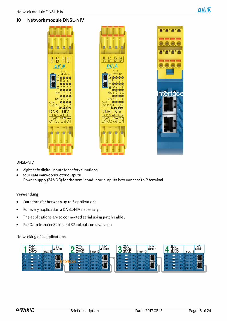
10 Network module DNSL-NIV
DNSL-NIV
• eight safe digital inputs for safety functions
• four safe semi-conductor outputs
Power supply (24 VDC) for the semi-conductor outputs is to connect to P terminal
Verwendung
• Data transfer between up to 8 applications
• For every application a DNSL-NIV necessary.
• The applications are to connected serial using patch cable .
• For Data transfer 32 in- and 32 outputs are available.
Networking of 4 applications
40NI01ZMV NIVZMVKZMVD 1 max. 131
ZMV NIV40NI01ZMVK
ZMVD 1 max. 132ZMV NIV
40NI01ZMVKZMVD 1 max. 133
ZMV NIV40NI01ZMVK
ZMVD 1 max. 134
Interface

Network Module DNSL-NRV
Brief description Date: 2017.08.15 Page 16 of 24
11 Network Module DNSL-NRV
Usage
• Networking up to 8 applications.
• The length of patch cable between the applications can be up to 150 m.
Networking of 8 applications
ZMVZMVKZMVD4
InterfaceInterface
ZMVZMVKZMVD3
ZMVZMVKZMVD2
ZMVZMVKZMVD1
NRV40NR01
ZMVZMVKZMVD8
InterfaceInterface
ZMVZMVKZMVD7
ZMVZMVKZMVD6
ZMVZMVKZMVD5
NRV40NR01
<150m-
13
1-max.
13
1-max.
13
1-max.
13
1-max.
NIV40NI02
NIV40NI02
NIV40NI02
NIV40NI02
13
1-max.
13
1-max.
NIV40NI02
NIV40NI02
NIV40NI02
NIV40NI0213
1-max.
13
1-max.
<150m-
<10m-

Terminals for safety functions
Brief description Date: 2017.08.15 Page 17 of 24
12 Terminals for safety functions
The following table shows modules with their available inputs (I) and in- outputs (IO). These can be used for different safety and not safety relevant functions.
Modules DNSL
Inputs in- outputs Designer Symbol
ZMV / ZMVK I1 I2 I3 I4 I5 I6 I7 I8 I9 I10 I11 I12 I13 I14 I15 I16 IO1 IO2 IO3 IO4
INV I1 I2 I3 I4 I5 I6 I7 I8 I9 I10 I11 I12 IO1 IO2 IO3 IO4
DSV / DRV I1 I2 I3 I4 I5 I6 I7 I8
SIV / IOV I1 I2 I3 I4 I5 I6 I7 I8
RMV / FBV
I1 I2 I3 I4 I5 I6 I7 I8
NIV I1 I2 I3 I4 I5 I6 I7 I8
FBV: Field bus
12.1 Analogue inputs at the central module
• I1 to I8 safe inputs for safety shutdown mats
• I1 to I8 safe analogue inputs for 0 to 10V
• I1 to I8 safe analogue inputs for 4 to 20mA
12.2 Inputs for function mode selection switch (FMSS) at central module
• 2 FMSS functions are at the central module available.
• Any inputs at SL VARIO and internal designer wiring can be used also.
• One switching position can be selected. No output signal if more or none
Selection Diagram Designer Symbol
1 to 4 : function mode 1 to 4
1
1
4
2
2 3
1
2 3 41
12.3 Inputs for Tow-Hand function according EN 574: Type IIIC
Activate both buttons within 500ms. Response time: < 50ms
Modules Inputs Control Diagram Designer Symbol
DNSL- E1 Q1 E2 Q2 Q1 E1 Q2E2
Q2E1
E2
2H
Q1
>500ms Q2
OK
<500ms
ZMV / ZMVK I1 I2 I3 I4
ZMV / ZMVK I5 I6 I7 I8
DRV/ DSV I1 I2 I3 I4
INV / IOV I1 I2 I3 I4
RMV / FBV I1 I2 I3 I4

Terminals for safety functions
Brief description Date: 2017.08.15 Page 18 of 24
12.4 Inputs for shut down mats, switch rails and bumpers at central module
• Up to eight short generating shutdown mats, switch
rails or bumpers can be monitored safely.
• The sensors have to be connected to I1-I8
accordingly to the schematic down.
• The output SM at the symbol has to be activated via the quit symbol. The quit symbol activate all
available shutdown mats.
•
• Mix configuration of the inputs I1-I8 is possible.
• The reaction time is ≤20ms
• Power supply: 24V DC +10%, -15% (PLV)
• Safety category 4/ PLe
• For other specifications see general technical data
DNSL-ZMV/ ZMVK/ ZMVD Schematic Designer Symbole
Voltage at I1-I8 Sensor active: 9.5V-14V Sensor free: 11.5V by 24V DC Sensor s: 24V
Mat, switch rail, bumper ZMV
8K
2
24V DC
I1
I8
SM
Quit In
Statically Quit via the Designer Manual Quit via the Designer
24V-element (+V) Quit element (RTSM) Mate input (SM1) switch output (K1)
24V-element (+V) Quit element (RTSM) (SM1) and (IN9.Quit) Starter element (SE1)
Starter Element (SE1) switch output (K1)
12.5 Important notes with using of shutdown mats, switch rails and bumpers
• The unit may only be installed and operated by those who are qualified electrical engineers or have received
sufficient training and are familiar with both these instructions and the current regulations for safety at work and accident prevention.
• At begin of the implementing and in frequently time distance the necessary checks (function, status, rating
and arrangement) must be undertaken of the user depending of the signal generator at the safety device.
• The safety function must be required every month if there is performance level (e) and every year if there is
PLd is required by using contact outputs.
• The maximal length of the connection wire is depended of the environment and the cross section of the wire.
Recommended maximal length 100 m
• The minimal safety distance of the signal generator of the protection device has to be determined according of DIN EN ISO 13855.
• The details in the instruction manual of the used signal generator must be considered and observed.
• Function parameters of the signal generator and control unit must be observed.
• Only signal generators with minimum 500.000 switch cycles respectively switch rails with minimum 11.000 switch cycles can be used.
• The contact load of the switch device outputs is to determinate according part: 14.5, page 22 to arrive the necessary switch cycles.
• The reaction time of the whole system is to consider.
• At the end of the service life the units have to be replaced.
• The replaced units have to be properly disposed. + -
• Faults and diagnostics via switching status LED the online diagnostics via the USB interface at the control
unit. Follow details have to be considered general technical data (page 21 and 22),
details in the Instruction manual of SL VARIO Designer

Terminals for safety functions
Brief description Date: 2017.08.15 Page 19 of 24
12.1 Inputs for Safety circuits (SC) with manual Quit
Safety circuits (SC) / input name (E, Q) / input (I)
Module SC1 SC3 SC5 SC7
DNSL- E11 E12 Q1 E21 E22 Q2 E31 E32 Q3 E41 E42 Q4
ZMV/ ZMVK I1 I2 I3 I5 I6 I7 I9 I10 I11 I13 I14 I15
INV I1 I2 I3 I5 I6 I7 I9 I10 I11
DSV / DRV I1 I2 I3 I5 I6 I7
DSIV / SIV I1 I2 I3 I5 I6 I7
IOV / RMV I1 I2 I3 I5 I6 I7
FBV/ NIV I1 I2 I3 I5 I6 I7
The control happens: parallel static, parallel via clock signal from SL VARIO or static antivalent.
12.2 Inputs for Safety circuits (SC) with Quit via Q
The quit signal is created in the Designer and wired to Q-input at the symbol. The quit signal happens via a terminal input, input at the field bus or a virtual output.
Safety circuits (SC) / input name (E, Q) / input (I)
Module SC1 SC2 SC3 SC4 SC5 SC6 SC7 SC8
DNSL- E11 E12 Q1 E21 E22 Q2 E31 E32 Q3 E41 E42 Q4 E51 E52 Q5 E61 E62 Q6 E71 E72 Q7 E81 E82 Q8
ZMV/ ZMVK I1 I2 Q I3 I4 Q I5 I6 Q I7 I8 Q I9 I10 Q I11 I12 Q I13 I14 Q I15 I16 Q
INV I1 I2 Q I3 I4 Q I5 I6 Q I7 I8 Q I9 I10 Q I11 I12 Q
DSV/ DRV I1 I2 Q I3 I4 Q I5 I6 Q I7 I8 Q
DSIV / SIV I1 I2 Q I3 I4 Q I5 I6 Q I7 I8 Q
IOV / RMV I1 I2 Q I3 I4 Q I5 I6 Q I7 I8 Q
FBV / NIV I1 I2 Q I3 I4 Q I5 I6 Q I7 I8 Q
FBV: Field bus
12.3 Inputs for Safety circuits (SC) without Quit
Safety circuits (SC) / input name (E) / input (I)
Module SC1 SC2 SC3 SC4 SC5 SC6 SC7 SC8
DNSL- E11 E12 E21 E22 E31 E32 E41 E42 E51 E52 E61 E62 E71 E72 E81 E82
ZMV / ZMVK I1 I2 I3 I4 I5 I6 I7 I8 I9 I10 I11 I12 I13 I14 I15 I16
INV I1 I2 I3 I4 I5 I6 I7 I8 I9 I10 I11 I12
DSV / DRV I1 I2 I3 I4 I5 I6 I7 I8
DSIV / SIV I1 I2 I3 I4 I5 I6 I7 I8
IOV / RMV I1 I2 I3 I4 I5 I6 I7 I8
FBV / NIV I1 I2 I3 I4 I5 I6 I7 I8
FBV: Field bus
Permission Static-parallel Safety door
Static antivalent Emergency stop
Clock-parallel
Q1
E2
E1
tt t>Qtt<Qt
E1
E2
Q
SK
E1
E2
11
12
21 22
Q
E1
E2
SK
Quit
E11
E12
Q1
E21
E22Q2
SK

Outputs at SL VARIO
Brief description Date: 2017.08.15 Page 20 of 24
13 Outputs at SL VARIO
Short-circuit-proof positive switching semiconductor outputs
DNSL- Switch current P-Level Description
ZMV
ZMVK A1 O1-O6 1A, ∑3A PLe
6 safe outputs O1, O2 monitored current
ZMV
ZMVK A1 IO1/2
IO3/4
0.1A ∑0.4A
PLe 4 clock outputs 4 safe outputs 4 safe digital inputs
DSV
DRV P O1/ O2
0.25A ∑0.4A
PLc 2 clock or switching outputs
DSV
DRV P O3-O7 1A ∑2.5A PLe
5 safe outputs O1, O4 also clock outputs
SIV
NIV P IO1-4 1A ∑2A PLd 4 safe outputs
INV A1 IO1-IO4 0.1A PLe 4 safe or clock outputs
IOV
DSIV
DSV
P O1-O7 1A ∑3,5A PLe 7 safe outputs O1-O4 also clock outputs
Safe contact outputs
DNSL- Switch currant P-Level Description
ZMV
ZMVD
K1 13 14
K2 23 24
≥10mA
≤6A
∑K1+K2: 6A
PLe
2 safe NO contact
DC13: 24V/ 2A AC15: 230V/ 3A
40ZM31/ 32 not available
ZMVK
K3 33 34 43 44 K4 53 54 63 64 K5 73 74 83 84 K6 93 94 103 104
≥10mA ≤6A
∑K3+K4: 6A
∑K5+K6: 6A
PLe
Output extension
4 outputs each 2 safe NO contacts DC13: 24V/ 5A
DNSL-RMV
K1 13 14 23 24 K2 33 34 43 44
≥10mA ≤6A
∑K1+K2: 6A
PLe
2 outputs each 2 safe NO contacts DC13: 24V/ 4A
AC15: 230V/ 3A
Designer Symbols
Safe output Clock output Safe contact Safe contacts Safe contacts
Safe output Clock output Clock output Safe output Safe output
The configuration of the outputs happens at Designer. A lot of diagnostics functions are available. This is useful for the setting-up operation and debugging.

General technical data
Brief description Date: 2017.08.15 Page 21 of 24
14 General technical data
14.1 Electrical characteristics
Operation voltage via A1, A2 at ZMV, ZMVK 24V DC, -15% + 10% for all modules, ≤10% Ripple
Input current at A1 ≤ 4A / internal fuse: 6A
DNSL- ZMV ZMVA ZMVD ZMVK DSV DSV2 DSIV DRV
Power consumption in W 2.9 3.0 3.0 7.7 2.5 2.5 2.5 2.5
Wight in g 350 450 450 570 130 130 130
DNSL- SIV INV IOV CMV NIV NRV RMV Feld Bus
Power consumption in W 2.2 1.7 2.2 0.5 2.2 0.5 4.8 1.0
Wight in g 130 130 130 130 130 130 140 130
14.2 Environment conditions
Operating temperature: -10 +55°C Storage temperature: -40 +85°C
Vibration resistance 3 axle Shock resistance 3 axle for output relay
Sinus 10–55Hz, 0,35mm, 10 cycles, 1 octave /min ≤ 5g, 11ms
Max. cable cross section 1 x( 0,2-1,0mm2 )with wire end sleeve
Terminal Spring load clamps, pluggable
Connection wire 60/75°C copper only
Housing material Polyamide PA unreinforced
Protection class Installation in a closed cabinet with ≥ IP 54
Voltage at the inputs by shutdown mat I1 to I8: 9.5 to 14V, 11.5V with 24V shutdown mat voltage
Reaction time by shutdown mat < 20ms
Voltage at the inputs 24V DC –15%, + 10%
Input current consumption Max. 4mA
Input voltage terminal(P) at DSV, DRV, SIV, IOV, NIV 24V DC -15% + 10%
Input current terminal(P) at DSV, DRV, SIV, IOV, NIV ≤ 4A
Input frequency at I9 – I12 at central module ≤ 1200Hz HTL-signals via as example proximity switches
Input frequency at I9 – I16 at central module ≤ 50KHz HTL-signals via incremental measuring system
Input frequency Encoder 1 and 2 at DNSL-DSV ≤ 500KHz Sin / Cos 1Vpp or TTL signals
Input frequency resolver 1 and 2 at DNSL-DRV ≤ 1200Hz Sin/ Cos 1 to 10Vpp
Input signals at DNSL-SIV SSI interface signals
Accuracy of the analogue inputs ± 3% of the maximal input value over -10 to +60°C
Input impedance of the analogue inputs With 4-20mA ca. 500Ω, with 0-10V > 5KΩ
Remark: current inputs (4-20mA) can be destroyed wit input voltage >12V
14.3 Technical data of the Semiconductor outputs
Technical data Semiconductor outputs ZMV/ ZMVK DSV, DRV INV IOV NIV, SIV
Outputs Performance level
IO1 - IO4 PLe
O1 – O6 PLe
O1, O2 PLc
O3 – O7 PLe
IO1 - IO4 PLe
O1 – O7 PLe
O1 – O4 PLd
Schematic of outputs Switch and continuous current Ω / L 0,1A 1A 0,25A 1A 100mA 1A 1A
Sum of Switch/continuous current Ω/L 0,4 3A 0,4A 2,5A 0.4A 3,5A 2A
Minimal Switch current Ω / L 1mA 1mA 1mA 1mA 1mA 1mA 1mA
• The power supply of the semiconductor outputs will be disconnected if the terminal A2 is not connected to 0V. Therefor residual voltage at the output loads is not possible.
• All semiconductor outputs are short circuit and overload proof.
• Every output has a recovery diode.

General technical data
Brief description Date: 2017.08.15 Page 22 of 24
14.4 Technical data of the contact outputs
Technical data contact outputs DNSL-ZMV/ ZMVK DNSL-ZMVK DNSL-RMV
Outputs K1, K2 K3 – K6 K1, K2
outputs schematic, Performance level: PLe Minimum switch current 10mA 10mA 10mA
switch current, 0,1Hz cycles according to DIN EN 60947-4-1/ EN 60947-5-1
DC1: 24V/6A DC13: 24V/2A
DC1: 24V/6A DC13: 24V/5A
DC1: 24V/6A DC13: 24V/4A
switch current according to DIN EN 60947-4-1/ EN 60947-5-1
AC1:250V/6A AC15: 230V/3A
AC1:250V/6A AC15: 230V/3A
Sum of the switch and continuous current ≤ 4A K3, K4:≤ 6A, K5, K6:≤6A K1: ≤ 4A, K2: ≤ 4A Electrical life DC13: 24V/ 1A 1.5x10
5 1x10
5 9x10
5
Electrical life DC13: 24V/ 4A 104 4x10
4 7x10
4
Electrical life AC15: 230V/ 1A 2x10⁵ 7x10
5
Electrical life AC15: 230V/ 2A 5x10⁵
Mechanical life > 50x106 > 10
7 > 40 x 10
6
Maxim switch cycles DC13: 4A 360 cycles/h 360 cycles /h 360 cycles /h Maxim switch cycles AC15: 3A 360 cycles /h 360 cycles /h Contact fuse 6A slow 6A slow 6A slow Short circuit strength: Automat safety fuse gG
200A/ B6 800A/ 6AgG
1000A SCPD 6A
200A/ B6 800A/ 6AgG
Rated insulation voltage 250V AC 250V AC Impulse withstand voltage Use in pollution degree 2 environment.
4KV 4KV
Reaction time, drop out time 15mS/12mS 10mS/ 3mS 10mS
AC1: control of none or low inductive load, AC voltage AC15: control of electro-magnetically load, AC voltage
DC1: control of none or low inductive load, DC voltage DC13: control of electro-magnetically load, DC voltage
14.5 Electrical life of the contact outputs
260 Work days / year/ 8h work time/ day/ switch voltage 24V DC Modules DNSL-ZMV, ZMVK: K1, K2 DNSL-ZMVK: K3-K6 DNSL-RMV: K1,K2 Last Art DC1 DC1 DC1 DC13 DC13 DC1 DC1 DC1 DC13 DC1 DC1 DC1 DC1 DC13 DC13 Schaltstrom 1.0A 4.0A 6.0A 1.0A 4A 1.0A 4.0A 6.0A 1.0A 4.0A 1.0A 4.0A 6.0A 1.0A 4.0A Jahre Schaltspiele/ 384 192 153 15 1 144 36 29 15 5 769 192 96 91 67 5 Stunde 192 96 76 7 0.5 77 17 14 7 2 384 96 48 45 33 10 96 48 38 3.6 0.25 38 8 7 3.6 1 192 48 24 23 17 20
260 Work days / year/ 8h work time/ day/ switch voltage 230V AC Modules DNSL-ZMV, ZMVK: K1, K2 DNSL-ZMVK: K3-K6 DNSL-RMV: K1,K2 Last Art AC1 AC1 AC1 AC15 AC15 AC1 AC1 AC1 AC15 AC15 AC1 AC1 AC1 AC15 AC15 Schaltstrom 0.5A 1.0A 3.0A 0.5A 1.0A 0.5A 1A 3.0A 0.5A 2A Jahre Schaltspiele/ 192 96 20 288 20 174 96 20 116 48 5 Stunde 96 48 10 144 10 87 48 10 58 24 10 48 24 5 72 5 44 24 15 28 12 20
DC1/ 24V
10
Sch
alts
pie
le / C
ycle
s
Schaltstrom (A) / Switching current (A)
DC13: 24V
DC1: 24V
7
105
104
0.1 0.5 1.0 2.0 3.0 4.0 5 6 10
106
DC13: 24V
AC15: 230V AC1: 230V
K3, K4, K5, K6
K1, K2
K3, K4, K5, K6 K1, K2K1, K2
K1, K2
DNSL-ZMV/ ZMVK K1-K6
10
Sch
alts
pie
le / C
ycle
s
Schaltstrom (A) / Switching current (A)
DC13
24VAC15
230V
AC1
230V
DC1
24V
7
106
105
104
0.1 0.5 1.0 2.0 3.0 4.0 5 6 10
DNSL-RMV K1 / K2

Dimensions
Brief description Date: 2017.08.15 Page 23 of 24
15 Dimensions
DNSL-ZMV 45 mm
DNSL-ZMVA, DNSL-ZMVK: 67.5 DNSL-ZMVD: 67.5 mm or 90 mm
Others 22.5 mm
Others 22.5 mm
Others 22.5 mm
DNSL-ZMVD: 67.5 mm with 4 standstill and speed monitoring 90.0 mm with 8 standstill and speed monitoring
15.1 Fitting and remove
Fitting: Plug bus connector at the cap rail. Hook the module up side at the cap rail. Push it down.
Remove: Screwdriver to unlock the module from the cap rail. Move the module to the up direction and take it out.
70-75 mm70-75 mm
(1)
(2)
(1)(3)
(4)
114.0
111
Cable channel distance
(1) (1) Bus connector : Grounding via DIN rail (2) Cap rail (3) Locking feeder (4) Cable channel

wir sind sicherheit. we are safety. DINA Elektronik GmbH
Esslinger Str. 84 D72649 Wolfschlugen Phone +49 7022 95 17 0 Fax +49 7022 95 17 700 [email protected] www.dina.de