
Bridging IMS and Internet Identity - Kantara Initiative IMS and Internet Identity Version: 1.0...
55
Bridging IMS and Internet Identity Version: 1.0 1 1 2 Bridging IMS and Internet Identity 3 Version: 1.0 4 Date: May 6, 2010 5 Editors: 6 Ingo Friese (Deutsche Telekom) 7 Jonas Högberg (Ericsson) 8 Mario Lischka (NEC) 9 Gaël Gourmelen (Orange) 10 Fulup Ar Foll (Sun) 11 Joni Brennan (IEEE-ISTO) 12 13 Contributors: 14 José Luis Mariz, Jesús de Gregorio and Carolina Canales (Ericsson) 15 Peter Weik (Fraunhofer FOKUS) 16 Joao Girao and Naoko Ito (NEC) 17 Shin Adachi (NTT) 18 Martin Meßmer (T-Systems) 19 20 Status: This document is a Kantara Initiative Draft Recommendation, created and 21 approved by the XXX WG (see section 3.8 of the Kantara Initiative Operating 22 Procedures) 23 24 Abstract: 25 26 Digital Identity has grown separately in IMS and Internet. While the one offers walled 27 garden services the other is focused on openness and third party integration. However, 28 for future Telco-business an inter-working of IMS and Internet is needed. A 29 methodology where real use cases are used shows the benefits for operators, SPs and 30 end-users by bridging these two worlds. These use cases cover the exposure of IMS 31 authentication to Web services, exposure of Web federations to IMS networks and 32 exposure of IMS resources to Web 3 rd parties. In an IMS domain, for SSO, SAML 33 assertions are conveyed in SIP messages. In a multi-domain world, the SSO solution 34 is based on a GAA/GBA solution. For attribute sharing, LAP ID-WSF messages are 35 used. When a Web Service Provider (WSP) exposes user data being retrieved from 36 the IMS a resolution of the mapping between the SAML identifier and the IMPU is 37 needed. The working assumption is that the user experience should be seamless while 38 keeping attention to security and privacy. The main findings and conclusions is that 39
Transcript of Bridging IMS and Internet Identity - Kantara Initiative IMS and Internet Identity Version: 1.0...
Bridging IMS and Internet Identity Version: 1.0
1
1
2
Bridging IMS and Internet Identity 3
Version: 1.0 4
Date: May 6, 2010 5
Editors: 6
Ingo Friese (Deutsche Telekom) 7
Jonas Högberg (Ericsson) 8
Mario Lischka (NEC) 9
Gaël Gourmelen (Orange) 10
Fulup Ar Foll (Sun) 11
Joni Brennan (IEEE-ISTO) 12
13
Contributors: 14
José Luis Mariz, Jesús de Gregorio and Carolina Canales (Ericsson) 15
Peter Weik (Fraunhofer FOKUS) 16
Joao Girao and Naoko Ito (NEC) 17
Shin Adachi (NTT) 18
Martin Meßmer (T-Systems) 19
20
Status: This document is a Kantara Initiative Draft Recommendation, created and 21
approved by the XXX WG (see section 3.8 of the Kantara Initiative Operating 22
Procedures) 23
24
Abstract: 25
26
Digital Identity has grown separately in IMS and Internet. While the one offers walled 27
garden services the other is focused on openness and third party integration. However, 28
for future Telco-business an inter-working of IMS and Internet is needed. A 29
methodology where real use cases are used shows the benefits for operators, SPs and 30
end-users by bridging these two worlds. These use cases cover the exposure of IMS 31
authentication to Web services, exposure of Web federations to IMS networks and 32
exposure of IMS resources to Web 3rd
parties. In an IMS domain, for SSO, SAML 33
assertions are conveyed in SIP messages. In a multi-domain world, the SSO solution 34
is based on a GAA/GBA solution. For attribute sharing, LAP ID-WSF messages are 35
used. When a Web Service Provider (WSP) exposes user data being retrieved from 36
the IMS a resolution of the mapping between the SAML identifier and the IMPU is 37
needed. The working assumption is that the user experience should be seamless while 38
keeping attention to security and privacy. The main findings and conclusions is that 39
Bridging IMS and Internet Identity Version: 1.0
Kantara Initiative DRAFT Recommendation
www.kantarainitiative.org
2
no new technologies are needed. It is enough for IMS and DigId technologies to 40
complement each other. The technical details are explained in the annexes. 41
42
Filename: Kantara_Bridging_IMS_Draft_Recommendation_v1.0.doc 43
44
Notice: 45
This document has been prepared by Participants of Kantara Initiative. Permission is 46
hereby granted to use the document solely for the purpose of implementing the 47
Specification. No rights are granted to prepare dérivative works of this Specification. 48
Entities seeking permission to reproduce portions of this document for other uses 49
must contact Kantara Initiative to determine whether an appropriate license for such 50
use is available. 51
52
Implementation or use of certain elements of this document may require licenses 53
under third party intellectual property rights, including without limitation, patent 54
rights. The Participants of and any other contributors to the Specification are not and 55
shall not be held responsible in any manner for identifying or failing to identify any or 56
all such third party intellectual property rights. This Specification is provided "AS 57
IS," and no Participant in Kantara Initiative makes any warranty of any kind, 58
expressed or implied, including any implied warranties of merchantability, non-59
infringement of third party intellectual property rights, and fitness for a particular 60
purpose. Implementers of this Specification are advised to review Kantara Initiative„s 61
website (http://www.kantarainitiative.org/) for information concerning any Necessary 62
Claims Disclosure Notices that have been received by the Kantara Initiative Board of 63
Trustees. 64
65
Copyright: The content of this document is copyright of Kantara Initiative. © 2010 66
Kantara Initiative. 67
68
69
70

Bridging IMS and Internet Identity Version: 1.0
Kantara Initiative DRAFT Recommendation
www.kantarainitiative.org
3
Table of Contents: 71 1 Introduction ...................................................................................................................................... 4 72 2 Problem Statements .......................................................................................................................... 5 73 3 Business perspectives ....................................................................................................................... 6 74 4 Use-Cases ....................................................................................................................................... 11 75
4.1 Exposure of Authentication from IMS to Web.......................................................................... 11 76 4.2 Exposure of Web Federations to IMS Networks ....................................................................... 12 77 4.3 Exposure of IMS resources to Web third-parties ...................................................................... 14 78
5 Technical solutions ......................................................................................................................... 15 79 5.1 Solution on Authentication from IMS to Web .......................................................................... 15 80
5.1.1 Overview 3GPP GBA ....................................................................................................... 16 81 5.2 Sharing the Authentication Context .......................................................................................... 17 82 5.3 Solution on IMS authentication to IMS third-parties ................................................................ 18 83
5.3.1 Using Federated Identities for Pseudonymity ................................................................... 18 84 5.3.2 Raise the Authentication Assurance and Acquiring Attributes......................................... 19 85
5.4 Solution on Exposure of IMS Resources to Web 3rd Party ...................................................... 20 86 5.5 Security ..................................................................................................................................... 21 87
6 Conclusion ...................................................................................................................................... 21 88 7 References ...................................................................................................................................... 21 89 A. Technical Annex A: "GBA & SAML Inter-working" .................................................................... 23 90
A.1 3GPP GBA ................................................................................................................................ 23 91 A.2 Advantages of a GBA Framework: ........................................................................................... 24 92 A.3 References ................................................................................................................................. 30 93
B. Technical Annex "Authentication context sharing between GBA and Web Client applications on 94 UEs" ....................................................................................................................................................... 31 95
B.1 Injection of Authentication context in a form of Cookie to Applications ................................. 31 96 B.1.1 Direct transfer of the cookie information between GBA Client and Web Client .................. 32 97 B.1.2 Cookie information retrieval from Identity Provider through Network ............................ 33 98
B.2 Consideration on Client deployment ......................................................................................... 34 99 B.3 The relationship with ID-WSF Advanced Client ...................................................................... 35 100 B.4 Conclusion................................................................................................................................. 35 101
C. Technical Annex : "SIP/SAML Messaging" .................................................................................. 36 102 C.1 Overview ................................................................................................................................... 36 103 C.2 Logical View ............................................................................................................................. 37 104
C.2.1 Domain View.................................................................................................................... 37 105 C.3 SIP/SAML Direct Variant ......................................................................................................... 38 106 C.4 SIP/SAML Artifact Variant....................................................................................................... 41 107 C.5 SIP/SAML Interaction for Outgoing Calls ................................................................................ 43 108 C.6 SIP/SAML Interaction for Incoming Calls ................................................................................ 48 109
D. Technical Annex: "Liberty ID-WSF and IMS inter-working" ....................................................... 51 110 D.1 IMS Application Server as a Liberty ID-WSF WSC................................................................. 51 111 D.2 IMS AS as a Liberty ID-WSF WSP .......................................................................................... 53 112
113
114

Bridging IMS and Internet Identity Version: 1.0
Kantara Initiative DRAFT Recommendation
www.kantarainitiative.org
4
1 Introduction 115
These days it is agreed that Identity Management (IdM) is a crucial component in a 116
service environment although the term identity is perceived differently in different 117
domains. This is true especially between the Internet and the telco domain where 118
fundamental differences could be identified. In the Internet environment, an identity is 119
usually associated with a username, while in the telco domain an identity is, for 120
example, an access customer. 121
122
Family members using the same fixed line telephone cannot truly be provided with 123
personal services since the users simply cannot be differentiated. On the other hand, 124
users of classic telco services like voice, fax and SMS do not need to handle and 125
maintain passwords, since they are authenticated by the network. In fact, they already 126
have seamless access. 127
128
Both the Internet and the telco-world have evolved their own identity solutions, 129
protocols and frameworks, because they have grown separately. On the way from the 130
Plain Old Telephony System (POTS) to the Next Generation Network (NGN) the 131
telco community developed and standardized the IP Multimedia Subsystem (IMS) as 132
a framework to describe the implementation of telco services based on the Internet 133
Protocol (IP). Although IMS standards foresee the development of advanced identity 134
mechanisms, they still specify a separated and rather closed world. Therefore, 135
interoperability between the Internet and IMS is still an issue and there is a growing 136
need for inter-working. Telcos develop Application Programming Interfaces (APIs) to 137
offer their assets to the Web community or to a 3rd party service provider. 138
Furthermore, they implement complex service scenarios containing Internet and telco 139
elements. 140
141
The Kantara Initiative Telecommunications Identity Work Group (TIWG) works 142
towards bridging those different worlds in order to enable convenient and seamless 143
service usage while maintaining security and privacy for the user. The capabilities that 144
Liberty Alliance Project federated IdM technology add to IMS for authentication and 145
user data exchanges have a positive influence for the telecom operator. Aided by these 146
capabilities, telco operators can manage their current business in a more efficient way. 147
New business opportunities will also arise that could generate new revenues. 148
Instead of proposing yet another framework the target of this white paper is to identify 149
the potential to leverage existing technologies and standards. The main focus is on 150
Liberty Identity Web Services Framework (ID-WSF) and Security Assertion Markup 151
Language (SAML) on the one side and 3GPP IP Multimedia Subsystem (IMS) on the 152
other. The leveraging of other standards, such as OpenID, is out of the scope of this 153
white paper. 154
155
In this paper we introduce examples of inter-working on the cross-roads of the 156
Internet and telco domain. Different approaches to seamless authentication and 157
service usage as well as attribute exchange across domains are discussed motivated by 158
business requirements and illustrated through use-cases. We briefly introduce the 159
Bridging IMS and Internet Identity Version: 1.0
Kantara Initiative DRAFT Recommendation
www.kantarainitiative.org
5
related technical specifications and standards and provide the details in a technical 160
annex. 161
This paper is the first step of the SIG Telco to bundle identity issues that are relevant 162
to the telecommunication industry. 163
2 Problem Statements 164
Both IMS and Web frameworks have to provide authentication and authorization 165
services. Both frameworks need to answer questions like: “Who are you? Are you 166
authorized for this? Where are you coming from? …” Nevertheless, while they must 167
answer the same class of questions, the chosen identity models are quite different. 168
169
1. Root of identity: IMS's identities are traditionally based on a reachable address (ex: 170
telephone number or sip address) when most Web applications expect identity to 171
be a pointer on some form of user profile (e.g. LDAP DN, User-ID, Customer 172
number). 173
2. Source of identity: IMS's identities are mostly provided by some form of trusted 174
element on the networks (e.g. mobile SIM/ UICC card) where Web applications 175
identities are created at server level, and are mapped to the device through a 176
network session (TCP) or through some form of application session (e.g. cookies, 177
session-ID). 178
3. Connectivity model: IMS devices will rarely connect directly to a given 179
application. Typically they pass through intermediaries (SIP proxy). On the other 180
hand, for Web applications intermediaries are limited to network equipments and 181
are invisible from the application. 182
183
IMS identities were base on the assumption that everything runs inside a well contain 184
and trusted environment. Alternatively, modern Web applications are designed 185
upfront with the assumption that the Internet cannot be trusted. In IMS one sticks one 186
or a few IMPU (IP Multimedia Public Identity) inside a device's SIM card/UICC 187
(Universal Integrated Circuit Card), and then exports those IMPU to every 188
application. When on the Internet each application has its own identity for a given 189
user. The direct result is that in IMS there is no “Single Sign-On (SSO)” issue. 190
However, because of the exported “public identity” (e.g. a unique TELURI or SIPURI) 191
a strong privacy constraint is inherited preventing the leveraging of 3rd parties 192
services. 193
On the Internet SAML2/Liberty solved the “Single Sign On” issue. Internet 194
applications now have a working model to address both usability (seamless end-user 195
experience), and privacy handling. Alternatively, IMS and telcos in general had a 196
tradition of handling everything in a closed and self contained circle of trust. Until 197
recently IMS and telcos were in a position to largely ignore the external world. 198
Privacy was well considered and „protected‟ as nothing was sent out to external 3rd 199
parties. In such a closed world providing users with a smooth experience was almost 200
simple. Nevertheless today people agree that leveraging to external services is a “must 201
have” feature. Telcos like many other players of the industry (ex: TV) need to find a 202
way to leverage this to external services providers. 203
Bridging IMS and Internet Identity Version: 1.0
Kantara Initiative DRAFT Recommendation
www.kantarainitiative.org
6
3 Business perspectives 204
It is obvious that both IMS and Web will continue to co-exist for some time. While 205
full convergence may occur in the long term future, operators need a working solution 206
to leverage both technologies sooner to make this co-existence seamless to customers. 207
If we look at a global mobile communication world, we can divide it into two parts: 208
Internal vs. external services (South - North): Internal services are very secure and 209
get a very fine grain visibility on customer profile (e.g. presence, geo-location, 210
pre/post paid), but these services are time consuming and expensive to develop. 211
Furthermore, it is harder each day for operators to impose new services (e.g. instant 212
messaging, social networking) in a walled-garden approach, without taking into 213
account external services and communities. External services on the other hand are 214
moving at Internet appropriate speeds to respond to customer demands. Nevertheless, 215
these external services are often not trusted and as a result rarely get access to 216
customers' Telecom internal profile. 217
IMS vs. Web protocols (West - East): If we spend time arguing the pro/cons of each 218
protocols stack, it is very clear that customers are not interested in which protocol a 219
given service uses. They simply want a seamless and fully transparent zapping 220
experience from one to the other. Most people agree that Web protocols are best 221
suited for user graphical interface and easier to integrate for external service 222
providers, While IMS, on the other hand, has a smarter method to handle multimedia 223
real-time streams and is better designed to interoperate with operators‟ backbones and 224
thus get better access to customer dynamic profiles (e.g. presence). 225
Bridging IMS and Internet Identity Version: 1.0
Kantara Initiative DRAFT Recommendation
www.kantarainitiative.org
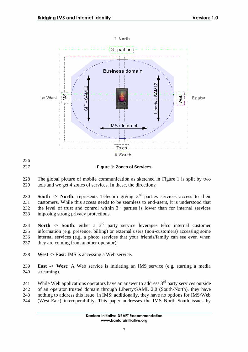
7
226
Figure 1: Zones of Services 227
The global picture of mobile communication as sketched in Figure 1 is split by two 228
axis and we get 4 zones of services. In these, the directions: 229
South -> North: represents Telecom giving 3rd
parties services access to their 230
customers. While this access needs to be seamless to end-users, it is understood that 231
the level of trust and control within 3rd
parties is lower than for internal services 232
imposing strong privacy protections. 233
North -> South: either a 3rd
party service leverages telco internal customer 234
information (e.g. presence, billing) or external users (non-customers) accessing some 235
internal services (e.g. a photo services that your friends/family can see even when 236
they are coming from another operator). 237
West -> East: IMS is accessing a Web service. 238
East -> West: A Web service is initiating an IMS service (e.g. starting a media 239
streaming). 240
While Web applications operators have an answer to address 3rd
party services outside 241
of an operator trusted domain through Liberty/SAML 2.0 (South-North), they have 242
nothing to address this issue in IMS; additionally, they have no options for IMS/Web 243
(West-East) interoperability. This paper addresses the IMS North-South issues by 244
Bridging IMS and Internet Identity Version: 1.0
Kantara Initiative DRAFT Recommendation
www.kantarainitiative.org
8
demonstrating how SAML 2.0 assertions can be embedded inside SIP protocol 245
messages without significant impact on the IMS network. On the West-East axis it is 246
shown how to leverage internal IMS attributes from 3rd Web applications. 247
The capabilities that LAP federated identity management technology adds to IMS for 248
authentication and user information exchange, as well as for service components 249
interaction on protocol layer among the HTTP and SIP services worlds, have a 250
positive influence in a number of operator business areas as follows: 251
Increased effectiveness in managing their current business: 252
Network operation simplification; The standardization efforts for creating a 253
simpler network to manage (all-IP, all-packet, one converged switch, one 254
converged user-centric DB) are nicely complemented in the architecture by 255
having user-centric access control functions, such as authentication and 256
authorization for all services and network accesses. LAP mechanisms 257
integrated with IMS and core network technologies provide an effective way 258
of implementing subscriber-centric functions as they unify the exposure of 259
those to all applications by utilizing widely accepted and standard application 260
developers techniques. 261
o The operator business case for this is measured mostly in terms of 262
Operating Expenditure (OPEX) reduction by the ability to centralize 263
operations on consolidated subscriber-centric infrastructure in the 264
network. Over time, a simpler network containing those functions also 265
delivers Capital Expenditure (CAPEX) savings by reducing the 266
number of network nodes necessary to be deployed as compared to a 267
service silo situation. 268
Fast Service Launch; A Service Creation Environment (SCE) that leverages 269
mostly on operators‟ network capabilities and provides optimal service 270
management routines requires a combination of IMS (mostly SIP technology 271
based) and SDP (mostly HTTP technology based) capabilities. Additionally, 272
for that SCE to be fully horizontal across applications and accesses, some 273
common support functions shall be shared by the SDP and IMS enablers. 274
Among those users identity and data management is the key. The utilization of 275
LAP mechanisms bridges IMS and HTTP capabilities, and also enables the 276
use of common federated user identity management functions in that service 277
creation environment. Utilization of LAP mechanisms also enables formatting 278
IMS information in terms of HTTP and offers unified HTTP-based application 279
integration mechanisms for all services. 280
The operator business case for this scenario is measured mostly in terms of OPEX 281
reduction average time and efforts to integrate a new application and launch a new 282
service. 283
Enabling new revenue generation and new business opportunities: 284

Bridging IMS and Internet Identity Version: 1.0
Kantara Initiative DRAFT Recommendation
www.kantarainitiative.org
9
New business models; once a user‟s identity, personal and content 285
information is exchanged through standard mechanisms across the Internet, 286
service delivery value chains are opened. This opening enables creativity for 287
new business models, as technology issues become less complex and less 288
expensive. Among possible new business roles, the role of the Identity 289
Provider (IdP) is crucial to the retention of current ownership of your final 290
customer. Additionally, the IdP role can serve as a building block towards 291
achieving other roles such as security provider, attribute provider and/or 292
payment provider. Operators can become brokers in the Internet for other 293
businesses through exploitation of some of their existing assets with regard to 294
Business to Consumer (B2C) Telecom services delivery. 295
o The operator business case in this scenario is measured mostly in terms 296
of new revenues through services commission (brokerage) and has 297
some strategic impact in terms of customer loyalty and marketed 298
values of their consumer-facing commercial brands 299
300
Increased service usage; enriching customer experience of services and 301
increasing the ability to be reachable by a critical mass of services are ways to 302
increase the Average Revenue per User (ARPU). Exposing the network user-303
centric views and context information to applications is the key to achieving 304
these improvements. Finding the right data model to be exposed to 305
applications through operator network information bits, and perhaps other 306
actors too, involves maximizing reach ability for many "raw" data sources. 307
This can be achieved through distributed infrastructures inside and outside 308
operators. Choosing the appropriate data model depends on the business 309
model that is used for delivering final user services, and both internal and 310
external federation capabilities such as those in LAP specifications are key 311
mechanisms to be able to share that data across infrastructure domains. 312
o The operator business case for this is measured mostly in terms of new 313
revenues for ARPU increase, and to some extent in reduction of churn 314
through current improvement of customer services experience. 315
Personalization of End User's Services; Knowing the customer by any consumer 316
facing brand such as the Telecoms operator becomes a key strategic activity, 317
especially in saturated markets. Tailoring applications based on user preference 318
significantly improve the user‟s experience and will increase customer loyalty. 319
Context information and user attributes contribute to personalizing services provided 320
by Business Support Systems (BSS). LAP mechanisms integrated with IMS and other 321
network DBs as well as network nodes containing dynamic information on user 322
behavior and service rendering enable exposure of aggregated meaningful data 323
models that can be easily integrated with many profiling applications. These 324
mechanisms can be easily added and changed at a low cost as they use „friendly‟ 325
application integration technologies and main stream (low cost) Web services 326
mechanisms. 327
Bridging IMS and Internet Identity Version: 1.0
Kantara Initiative DRAFT Recommendation
www.kantarainitiative.org
10
The operator business case can only be measured in 2 ways: 328
Indirectly in terms of improvements in the evolution of customer loyalty/churn 329
rates; and 330
Strategically in terms of improvements in their consumer brand value. 331
These capabilities being used by operators in turn provide some benefits to end-users 332
and other service providers as: 333
End-Users: 334
Higher security and privacy protection; The ability to reuse the network 335
embedded security mechanisms of operators for user interactions with all 336
services inside the operator realm and across the Internet increases the 337
level of security and privacy protection compared to what exists today. As 338
well as enabling end-users to utilize a transaction broker brand like an 339
operator that is trustable and that can legally be responsible for the security 340
level involved in the transaction. 341
Richer services experience; The ability to exchange more information 342
across and combine service capabilities among operators and other service 343
providers will offer end-users with a larger variety of services as well as 344
richer service experiences across various terminals and access networks, 345
with a common service look and feel, with personalization and having the 346
service delivery adapted and optimized for the end-user contextual 347
situation in real-time. 348
349
Bridging IMS and Internet Identity Version: 1.0
Kantara Initiative DRAFT Recommendation
www.kantarainitiative.org
11
Service Providers: 350
Focus on core business; The ability to exchange capabilities in an 351
interoperable and secure manner opens up value chains and provides more 352
opportunities for final service providers to outsource some of these 353
capabilities to new business mediation actors. So focus can be on their 354
truly core business processes, therefore saving costs and getting a more 355
competitive edge through more dedication to their business differentiation. 356
Utilization of richer and wider delivery channels; Networks with 357
enriched capabilities from operators that become easily accessible to 358
service providers widen significantly the distribution channel of any 359
service. This is as end-users move more of their daily interactions to the 360
online world and become more and more mobile and multi-terminal in all 361
their services usage. Additionally, some of those capabilities are quite 362
unique in terms of information available within a network operator 363
domain. So, it becomes also a much richer service delivery channel 364
compared to existing ones and so allowing the service provider to build 365
additional service differentiation. 366 367
4 Use-Cases 368
This section presents concrete use-cases illustrating inter-working between IMS and 369
Web worlds as introduced in the previous section. While the first coming use-case is 370
more related to IMS in mobile operators' context, the next ones apply to both fixed 371
and mobile contexts. 372
373
4.1 Exposure of Authentication from IMS to Web 374
The following use-case illustrates how we seamlessly expose the IMS authentication 375
done within the operator domain to access a Web application provided by an external 376
party on the Internet ("South-West->North-East" direction as depicted in chapter 3). 377
This enables the provision of a consistent and efficient user experience, wherever the 378
resource is stored and independent of the current type of network connection. 379
Bridging IMS and Internet Identity Version: 1.0
Kantara Initiative DRAFT Recommendation
www.kantarainitiative.org
12
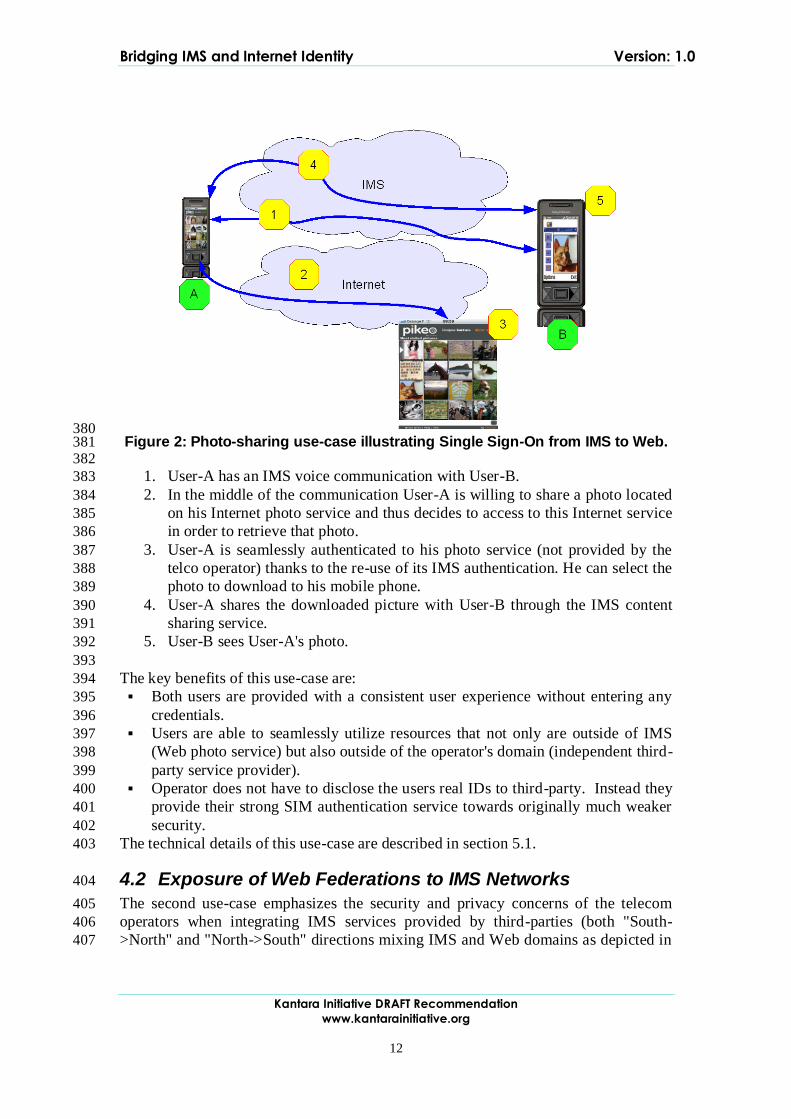
380 Figure 2: Photo-sharing use-case illustrating Single Sign-On from IMS to Web. 381
382
1. User-A has an IMS voice communication with User-B. 383
2. In the middle of the communication User-A is willing to share a photo located 384
on his Internet photo service and thus decides to access to this Internet service 385
in order to retrieve that photo. 386
3. User-A is seamlessly authenticated to his photo service (not provided by the 387
telco operator) thanks to the re-use of its IMS authentication. He can select the 388
photo to download to his mobile phone. 389
4. User-A shares the downloaded picture with User-B through the IMS content 390
sharing service. 391
5. User-B sees User-A's photo. 392
393
The key benefits of this use-case are: 394
Both users are provided with a consistent user experience without entering any 395
credentials. 396
Users are able to seamlessly utilize resources that not only are outside of IMS 397
(Web photo service) but also outside of the operator's domain (independent third-398
party service provider). 399
Operator does not have to disclose the users real IDs to third-party. Instead they 400
provide their strong SIM authentication service towards originally much weaker 401
security. 402
The technical details of this use-case are described in section 5.1. 403
4.2 Exposure of Web Federations to IMS Networks 404
The second use-case emphasizes the security and privacy concerns of the telecom 405
operators when integrating IMS services provided by third-parties (both "South-406
>North" and "North->South" directions mixing IMS and Web domains as depicted in 407

Bridging IMS and Internet Identity Version: 1.0
Kantara Initiative DRAFT Recommendation
www.kantarainitiative.org
13
chapter 3). In the given case, the operator does not disclose user's real IDs (ie phone 408
number) to third-party applications. 409
410
411 Figure 3: Ads website (provided by a third-party) use-case illustrating 412
consistent user-experience in both Web and IMS contexts as well as privacy 413 concerns. 414
415
1. User-A wants to sell an item through an online ads website. Before posting his 416
advertisement, User-A needs to create an account at that site. He can either fill 417
in all the requested information or opt for a one-click privacy-enabled 418
registration, leveraging existing partnership between his telecom operator and 419
this third-party website. 420
2. User-A chooses the one-click process and is requested to authenticate with his 421
telecom operator (acting as an Identity Provider) in order to federate accounts. 422
During this process, the telecom operator will provide an alias instead of real 423
user IDs (i.e. phone number). The benefit for users is that the website cannot 424
publish User-A phone number as it does get it. The website only relies on 425
aliases provided by the telecom operator in order to reach users. 426
3. User-A can now edit and then post his new ad. Depending on his preferences, 427
"click to call" / "click to contact" buttons are automatically added in order to 428
reach him by phone, instant messaging or email, this without revealing his real 429
IDs (either fixed or mobile phone number, email address, …). 430
431
Other users can now search and access to this new ad through the ads website. 432
A. User-B is browsing on this ads site and is interested by User-A's ad. 433
B. In order to get more information, User-B clicks on the "click to call" button to 434
initiate a phone call with User-A. 435
C. The ads service acts as an intermediary in order to bootstrap the connection 436
between User-B and User-A based on the alias. 437
D. This call is automatically routed to the right device for User-A either fixed or 438
mobile (thanks to the telecom operator infrastructure) and the 439
telecommunication is established between User-A and User-B. 440
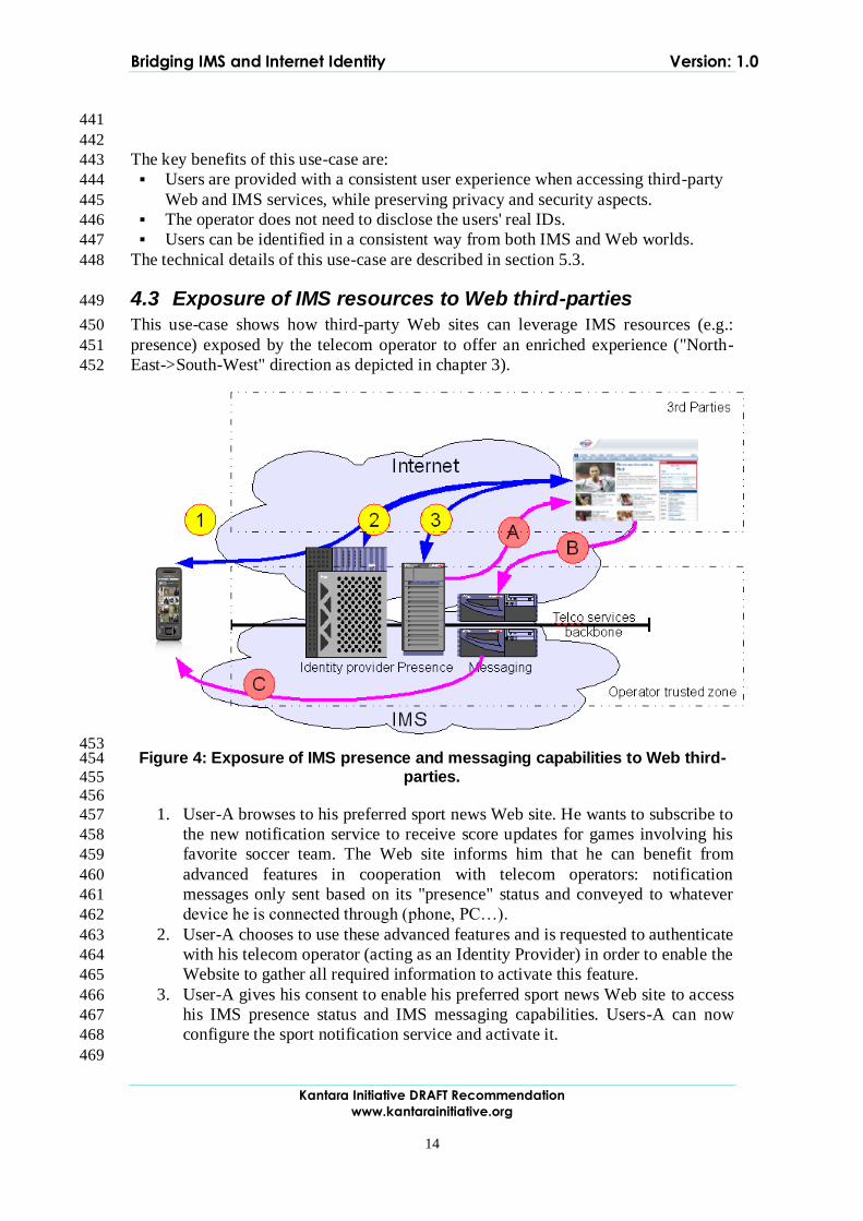
Bridging IMS and Internet Identity Version: 1.0
Kantara Initiative DRAFT Recommendation
www.kantarainitiative.org
14
441
442
The key benefits of this use-case are: 443
Users are provided with a consistent user experience when accessing third-party 444
Web and IMS services, while preserving privacy and security aspects. 445
The operator does not need to disclose the users' real IDs. 446
Users can be identified in a consistent way from both IMS and Web worlds. 447
The technical details of this use-case are described in section 5.3. 448
4.3 Exposure of IMS resources to Web third-parties 449
This use-case shows how third-party Web sites can leverage IMS resources (e.g.: 450
presence) exposed by the telecom operator to offer an enriched experience ("North-451
East->South-West" direction as depicted in chapter 3). 452
453 Figure 4: Exposure of IMS presence and messaging capabilities to Web third-454
parties. 455 456
1. User-A browses to his preferred sport news Web site. He wants to subscribe to 457
the new notification service to receive score updates for games involving his 458
favorite soccer team. The Web site informs him that he can benefit from 459
advanced features in cooperation with telecom operators: notification 460
messages only sent based on its "presence" status and conveyed to whatever 461
device he is connected through (phone, PC…). 462
2. User-A chooses to use these advanced features and is requested to authenticate 463
with his telecom operator (acting as an Identity Provider) in order to enable the 464
Website to gather all required information to activate this feature. 465
3. User-A gives his consent to enable his preferred sport news Web site to access 466
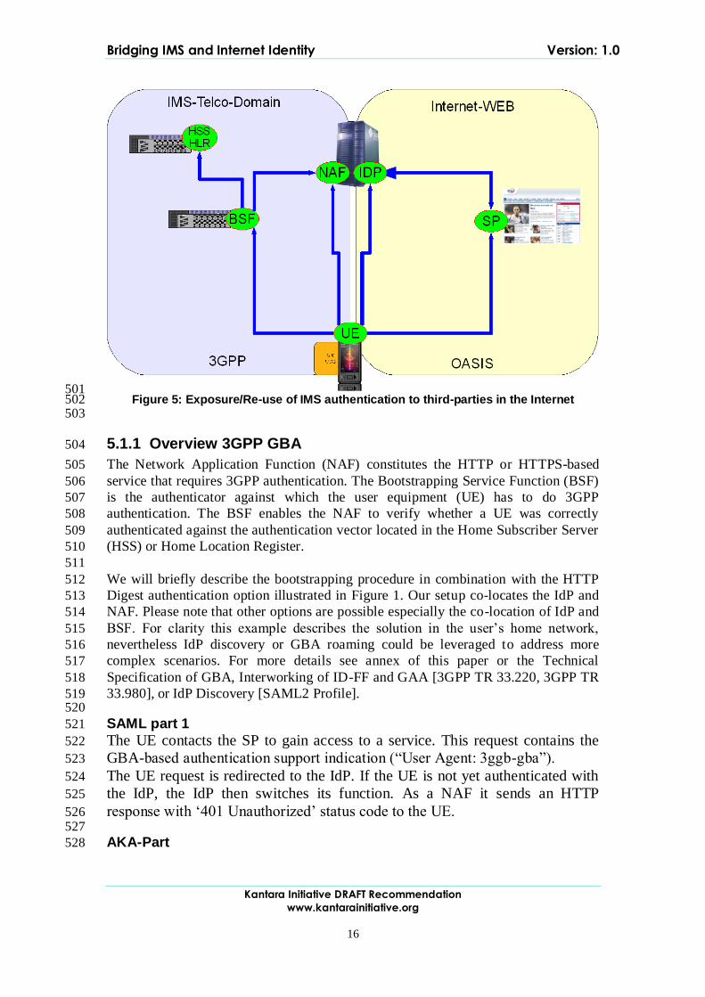
his IMS presence status and IMS messaging capabilities. Users-A can now 467
configure the sport notification service and activate it. 468
469
Bridging IMS and Internet Identity Version: 1.0
Kantara Initiative DRAFT Recommendation
www.kantarainitiative.org
15
Later on, during the soccer game event: 470
A. The sport news service is notified of the presence status of user A. 471
B. Depending on the presence status of user A, the sport news service will send 472
him messages to inform him of updated scores. 473
C. The telecom operator routes the message to the right device and User-A is 474
informed in real-time. 475
476
The key benefits of this use-case are: 477
Users and third parties Web sites are able to leverage resources from the IMS in 478
order to provide advanced features combining presence and messaging 479
capabilities (routing to the right device). 480
Users do not need to disclose their real IDs (phone number …) to third-party 481
Web-sites. 482
483
The details of this use-case are described in section 5.4. 484 485
5 Technical solutions 486
This section aims to describe the technical solutions that correspond to each use-case 487
presented in the previous section. The objective is to leverage existing technologies 488
and standard specifications in both Web (such as Liberty/SAML ones) and IMS 489
worlds. This section also aims to show how existing technologies can integrate 490
together to provide solutions to the identified needs. These existing technologies and 491
standard specifications are referenced here rather than explained in details in order to 492
focus on the main inter-working concepts (though technical details can be found in 493
annexes for each of the described solutions). 494
5.1 Solution on Authentication from IMS to Web 495
SAML 2.0 is the framework of choice for Identity management and SSO for Web-496
based services. The combination of SAML 2.0 with the Generic bootstrapping 497
architecture of 3GPP enables the leveraging of SIM-based, accepted, strong and 498
mutual authentication to the Web. 499
500
Bridging IMS and Internet Identity Version: 1.0
Kantara Initiative DRAFT Recommendation
www.kantarainitiative.org
16
501 Figure 5: Exposure/Re-use of IMS authentication to third-parties in the Internet 502
503
5.1.1 Overview 3GPP GBA 504
The Network Application Function (NAF) constitutes the HTTP or HTTPS-based 505
service that requires 3GPP authentication. The Bootstrapping Service Function (BSF) 506
is the authenticator against which the user equipment (UE) has to do 3GPP 507
authentication. The BSF enables the NAF to verify whether a UE was correctly 508
authenticated against the authentication vector located in the Home Subscriber Server 509
(HSS) or Home Location Register. 510
511
We will briefly describe the bootstrapping procedure in combination with the HTTP 512
Digest authentication option illustrated in Figure 1. Our setup co-locates the IdP and 513
NAF. Please note that other options are possible especially the co-location of IdP and 514
BSF. For clarity this example describes the solution in the user‟s home network, 515
nevertheless IdP discovery or GBA roaming could be leveraged to address more 516
complex scenarios. For more details see annex of this paper or the Technical 517
Specification of GBA, Interworking of ID-FF and GAA [3GPP TR 33.220, 3GPP TR 518
33.980], or IdP Discovery [SAML2 Profile]. 519 520
SAML part 1 521
The UE contacts the SP to gain access to a service. This request contains the 522
GBA-based authentication support indication (“User Agent: 3ggb-gba”). 523
The UE request is redirected to the IdP. If the UE is not yet authenticated with 524
the IdP, the IdP then switches its function. As a NAF it sends an HTTP 525
response with „401 Unauthorized‟ status code to the UE. 526 527
AKA-Part 528
Bridging IMS and Internet Identity Version: 1.0
Kantara Initiative DRAFT Recommendation
www.kantarainitiative.org
17
The UE recognizes from the HTTP 401 response that it is requested to supply 529
NAF-specific keys. Since it has not yet authenticated against the BSF it 530
initiates the so called ISIM/AKA authentication by sending a request to the 531
BSF including its IMS Private Identity (IMPI). 532
533
The BSF extracts the IMPI and fetches a set of authentication information for 534
that identity from the HSS and sends back a derived user MD5 challenge. 535
536
The UE checks the challenge and calculates the corresponding response by 537
means of the application of the IP Multimedia Services Identity Module (ISIM) 538
at the Universal Integrated Circuit Card (UICC) and sends them to the BSF. 539
540
The BSF will now compare the response with the expected values and will 541
eventually derive a session key (Ks-NAF) and store it together with a self-542
generated BSF-Transaction Identifier (B-TID). It will then send back the B-543
TID and a key lifetime parameter to the UE. 544
545
SAML part 2 546
The UE answers with a HTTP GET request containing as a username the B-TID and 547
as a password the Ks_NAF. The UE may include further LAP related user data (e.g. 548
public user ID). 549
550
The IdP responds with a SAML artifact in the HTTP Response redirect URL. The UE 551
contacts the SP again using this URL and the SAML artifact. The SP sends a request 552
with the SAML artifact to the IdP. 553
554
The IdP can now construct and send the requested assertion. The SP verifies the 555
message and answers with a HTTP Response and the requested content. 556
Further technical details could be found in the Technical Annex A: "GBA & ID FF 557
Interworking". 558
5.2 Sharing the Authentication Context 559
In the above solution, a tight coupling of the GBA client and the Web client is 560
assumed. As an alternative we introduce two solutions for supporting existing Web 561
client applications. Both mechanisms use the cookie information to convey the 562
authentication context from IMS domain which is accessed via the GBA Client to 563
Web domain accessed by the browser. The basic concept is that a GBA client 564
provides the IdP with the cookie information conveying the authentication context. 565
Then a Web browser starts LA ID-FF based access to SP upon a successful GBA 566
authentication and redirected to the IdP to retrieve the Authentication Assertion. 567
The first option is to let the Web Client application get the cookie information directly 568
from the GBA Client belonging to the same user. The GBA Client retrieves the 569
cookie information upon a successful GBA authentication and passes it to the Web 570
Client. This option is possible only when a Web Client (browser) exposes such 571
functionality for a plug-in to insert cookie information offline. 572
Bridging IMS and Internet Identity Version: 1.0
Kantara Initiative DRAFT Recommendation
www.kantarainitiative.org
18
The second option is to pass the Web Client application a temporal URI under the 573
Identity Provider domain to fetch the cookie information through. This URI is a 574
dedicated URI to a specific successful authentication and only valid for a certain 575
period after the successful authentication. The GBA Client retrieves the URL upon a 576
successful GBA authentication and passes it to the Web Client. The Web Client will 577
then access the URL injecting the cookie information subsequently. Further details are 578
presented in the Technical Annex B: "Authentication context sharing between GBA 579
and Web Client applications on UEs". 580 581
5.3 Solution on IMS authentication to IMS third-parties 582
SAML is a set of protocol specifications that provide, among other things, seamless 583
SSO and attribute exchange in a distributed environment. In particular, once a user 584
has authenticated towards a trusted entity called the IdP, the SAML protocols enable 585
the IdP and the SPs to exchange information about the user's authentication status at 586
the IdP in a secure manner and in a way that takes into account the user's privacy. We 587
will discuss now how a SIP/SAML binding could be used to exchange information 588
5.3.1 Using Federated Identities for Pseudonymity 589
The Application Server tries to establish an incoming call towards User-A. The 590
Application Server can be hosted in the same network as User-A. The Application 591
Server could also be hosted in another IMS network or even outside of an IMS 592
domain. It is assumed that there is an existing relationship between the user‟s IdP and 593
the Application Server. The establishment of this federation is described in 594
[SAML2Core]. 595
Any of these initial steps enable the Application Server to reach the user via a 596
pseudonym, which could be resolved at the IdP. 597
598
Then the application server is able to initiate a session with this pseudonym as a callee. 599
The message is routed through the IMS network towards the IdP given in the 600
pseudonym of the user as indicated in Figure 6. The IdP is able to resolve the 601
pseudonym used by the application server into the corresponding IP Multimedia 602
Public Identity (IMPU) of the user. In order to provide user privacy a new session is 603
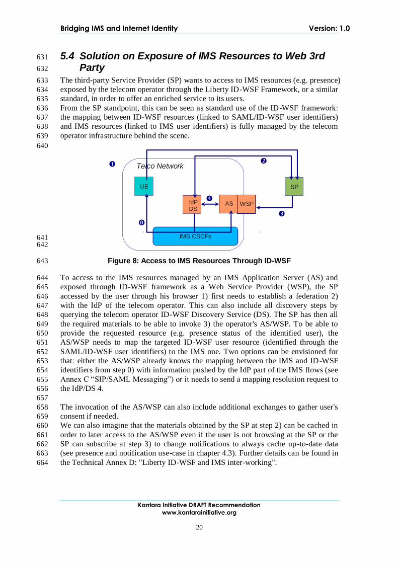
initiated by the IdP. The corresponding message is routed via the IMS network to the 604
registered UE of the user. The IdP in addition to its traditional role is acting as a back-605
to-back proxy. Alternatively, an additional box could play this role. All replies and the 606
following messages are routed via the IdP, which exchanges the IMPU of the user and 607
the pseudonym accordingly (c.f. [TR 33.980]). 608
609
In case the user wants to establish an outgoing call using a pseudonym towards the 610
application server, the flow is inversed to the one shown in Figure 6. 611
Bridging IMS and Internet Identity Version: 1.0
Kantara Initiative DRAFT Recommendation
www.kantarainitiative.org
19
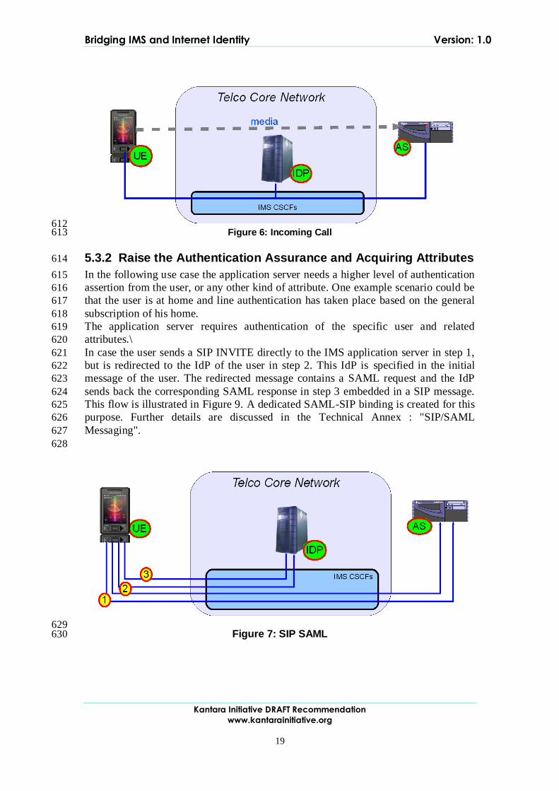
612 Figure 6: Incoming Call 613
5.3.2 Raise the Authentication Assurance and Acquiring Attributes 614
In the following use case the application server needs a higher level of authentication 615
assertion from the user, or any other kind of attribute. One example scenario could be 616
that the user is at home and line authentication has taken place based on the general 617
subscription of his home. 618
The application server requires authentication of the specific user and related 619
attributes.\ 620
In case the user sends a SIP INVITE directly to the IMS application server in step 1, 621
but is redirected to the IdP of the user in step 2. This IdP is specified in the initial 622
message of the user. The redirected message contains a SAML request and the IdP 623
sends back the corresponding SAML response in step 3 embedded in a SIP message. 624
This flow is illustrated in Figure 9. A dedicated SAML-SIP binding is created for this 625
purpose. Further details are discussed in the Technical Annex : "SIP/SAML 626
Messaging". 627
628
629 Figure 7: SIP SAML 630
Bridging IMS and Internet Identity Version: 1.0
Kantara Initiative DRAFT Recommendation
www.kantarainitiative.org
20
5.4 Solution on Exposure of IMS Resources to Web 3rd 631
Party 632
The third-party Service Provider (SP) wants to access to IMS resources (e.g. presence) 633
exposed by the telecom operator through the Liberty ID-WSF Framework, or a similar 634
standard, in order to offer an enriched service to its users. 635
From the SP standpoint, this can be seen as standard use of the ID-WSF framework: 636
the mapping between ID-WSF resources (linked to SAML/ID-WSF user identifiers) 637
and IMS resources (linked to IMS user identifiers) is fully managed by the telecom 638
operator infrastructure behind the scene. 639
640
641 642
Figure 8: Access to IMS Resources Through ID-WSF 643
To access to the IMS resources managed by an IMS Application Server (AS) and 644
exposed through ID-WSF framework as a Web Service Provider (WSP), the SP 645
accessed by the user through his browser 1) first needs to establish a federation 2) 646
with the IdP of the telecom operator. This can also include all discovery steps by 647
querying the telecom operator ID-WSF Discovery Service (DS). The SP has then all 648
the required materials to be able to invoke 3) the operator's AS/WSP. To be able to 649
provide the requested resource (e.g. presence status of the identified user), the 650
AS/WSP needs to map the targeted ID-WSF user resource (identified through the 651
SAML/ID-WSF user identifiers) to the IMS one. Two options can be envisioned for 652
that: either the AS/WSP already knows the mapping between the IMS and ID-WSF 653
identifiers from step 0) with information pushed by the IdP part of the IMS flows (see 654
Annex C “SIP/SAML Messaging”) or it needs to send a mapping resolution request to 655
the IdP/DS 4. 656
657
The invocation of the AS/WSP can also include additional exchanges to gather user's 658
consent if needed. 659
We can also imagine that the materials obtained by the SP at step 2) can be cached in 660
order to later access to the AS/WSP even if the user is not browsing at the SP or the 661
SP can subscribe at step 3) to change notifications to always cache up-to-date data 662
(see presence and notification use-case in chapter 4.3). Further details can be found in 663
the Technical Annex D: "Liberty ID-WSF and IMS inter-working". 664
IMS CSCFs
UE SP
IdP DS
Telco Network
AS WSP
Bridging IMS and Internet Identity Version: 1.0
Kantara Initiative DRAFT Recommendation
www.kantarainitiative.org
21
5.5 Security 665
The proposed solutions leverage SAML2 and 3GPP security models and inherit their 666
capabilities and limitations. [SAML2Core, 3GPP TR 33.980] 667
6 Conclusion 668
The IMS and Digital Identity worlds have grown separately offering two types of 669
services, walled-garden and third-party. There is a need to bridge the two worlds. The 670
idea is to do this in such a way that the user experience will be seamless while 671
keeping attention to security and privacy. The assumption is that no fundamental 672
changes are needed, i.e. existing technologies should be leveraged. 673
674
The business drivers for an operator bridging these worlds are: 675
Increased effectiveness in managing their current business; and 676
Enablement of new revenue generation and new business opportunities. 677
Benefits can be seen on various levels, e.g., OPEX, CAPEX, ARPU and new revenue 678
streams. 679
To simplify the user experience, seamless access to third-party services across 680
domains/IMS worlds is looked upon. This would be by offering seamless 681
authentication across the domains/IMS worlds (SSO) and seamless service usage 682
across domains by leveraging users‟ resources exposed in both worlds (attribute 683
sharing). 684
Through some realistic use cases on how to expose IMS authentication and IMS 685
resources to third-parties technical solutions are proposed. For SSO, the solutions are 686
based on the idea to convey SAML assertions in SIP messages when the domain is 687
IMS. When the domain is across worlds the proposed solution is based on the 3GPP 688
security architecture GAA/GBA. For attribute sharing standard ID-WSF message 689
flows are proposed. When an WSP exposes user data retrieved from the IMS, i.e., 690
when the WSP acts as both a WSP in the Web domain and as an IMS AS in the IMS 691
domain, a resolution of the mapping between the received SAML federation identifier 692
and the IMPU is needed. 693
It has been shown that no new technologies are needed; it is enough to let IMS and 694
digital identity complement each other to solve the mentioned problems. The aim is to 695
continue and study how the IMS and digital identity worlds can complement each 696
other. 697 698
7 References 699
3GPP TR
33.220
Generic Authentication Architecture (GAA); Generic
bootstrapping architecture http://www.3gpp.org/ftp/Specs/html-
info/33220.htm
3GPP TR
33.980
- Liberty Alliance and 3GPP security interworking; Interworking
of Liberty Alliance Identity Federation Framework (ID-FF),
Identity Web Services Framework (ID-WSF) and Generic
Authentication Architecture (GAA);
http://www.3gpp.org/ftp/Specs/html-info/33980.htm
Bridging IMS and Internet Identity Version: 1.0
Kantara Initiative DRAFT Recommendation
www.kantarainitiative.org
22
SAML2Core Assertions and Protocols for the OASIS Security Assertion
Markup Language
(SAML) V2.0 Working Draft 12 February 2007 http://www.oasis-
open.org/committees/download.php/22385/sstc-saml-core-errata-
2.0-wd-04-diff.pdf
SAML2 Profiles Profiles for the OASIS Security Assertion Markup Language
(SAML) V2.0
OASIS Standard, 15 March 2005
Bridging IMS and Internet Identity Version: 1.0
23
A. Technical Annex A: "GBA & SAML Inter-working" 700
701
Telcos are in an ideal position to become the Identity Provider of choice for 702
consumers and business partners. Firstly, Telcos already have established 703
relationships with millions of end customers. They administrate identities in the form 704
of customer data sets with e.g. name, address and accounts. Integrated providers and 705
wireless Telcos already have a widely deployed and established authentication 706
instrument, basically the SIM/UICC card (Subscriber Identity Module/Universal 707
Integrated Circuit Card) and have thus the basic technical requirement to be an 708
authentication service provider and identity provider. 709
710
The Generic Bootstrapping Architecture (GBA) defined within 3GPP includes a 711
solution for the reuse of authentication in the mobile world, on the basis of SIM/UICC. 712
This type of smart card in mobile 3G devices contains all the required credentials and 713
functionalities necessary for authentication. With GBA it is possible that a user also 714
registers with web-based services via his UICC, which is typically used to sign-on to 715
services like mobile telephony. 716
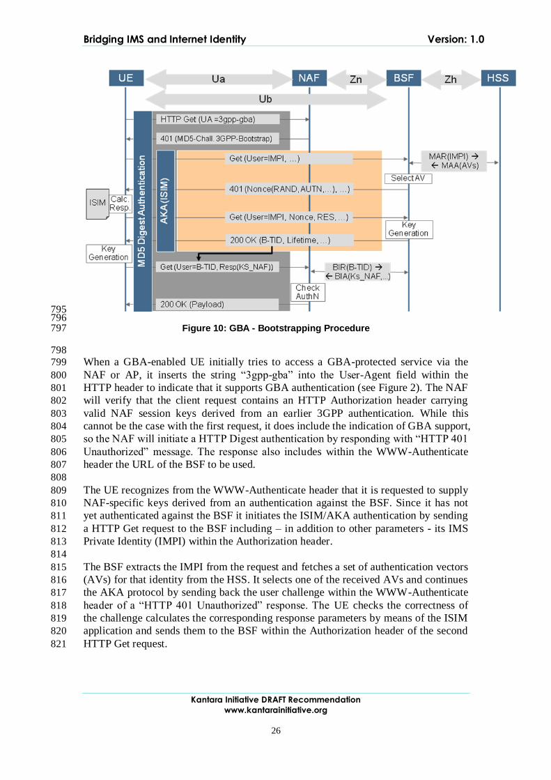
717
The reuse of the network authentication for web-based services is a valuable asset of a 718
Telco and an important step to converged services. Reuse of network authentication is 719
a convergent approach that brings the assets of the network into the service layer. It 720
enables an easy and unhindered use of services based on a secure network 721
authentication 722
723
This chapter describes the combination of the Generic Bootstrapping Architecture and 724
Liberty Alliance Identity Framework based on technical report [3GPP TR 33.980] and 725
the results of a Project Next Generation Network AAA of Deutsche Telekom 726
Laboratories. 727 728
A.1 3GPP GBA 729
730
In UMTS Release 6 the 3GPP has started to define the GAA (Generic Authentication 731
Architecture) as the framework for various peer authentication methods within the 732
NGN world, in particular for Internet-based services (see [3GPP-TS33.919]). Within 733
the GAA the Generic Bootstrapping Architecture (GBA) defines the functions that are 734
required to authenticate a client to a Web-based service using his 3G subscription (see 735
[3GPP-TS33.220]). 736 737
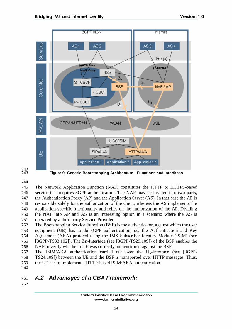
A.1.1 Architecture 738
Figure 9 gives an overview of how the GBA fits into the 3GPP world in comparison 739
to the IMS environment. It highlights the new functions and interfaces introduced by 740
the GBA. 741
Bridging IMS and Internet Identity Version: 1.0
Kantara Initiative DRAFT Recommendation
www.kantarainitiative.org
24
742 Figure 9: Generic Bootstrapping Architecture - Functions and Interfaces 743
744
The Network Application Function (NAF) constitutes the HTTP or HTTPS-based 745
service that requires 3GPP authentication. The NAF may be divided into two parts, 746
the Authentication Proxy (AP) and the Application Server (AS). In that case the AP is 747
responsible solely for the authorization of the client, whereas the AS implements the 748
application-specific functionality and relies on the authorization of the AP. Dividing 749
the NAF into AP and AS is an interesting option in a scenario where the AS is 750
operated by a third party Service Provider. 751
The Bootstrapping Service Function (BSF) is the authenticator, against which the user 752
equipment (UE) has to do 3GPP authentication, i.e. the Authentication and Key 753
Agreement (AKA) protocol using the IMS Subscriber Identity Module (ISIM) (see 754
[3GPP-TS33.102]). The Zn-Interface (see [3GPP-TS29.109]) of the BSF enables the 755
NAF to verify whether a UE was correctly authenticated against the BSF. 756
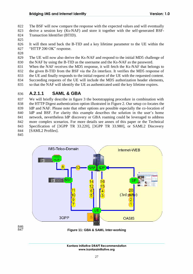
The ISIM/AKA authentication carried out over the Ub-Interface (see [3GPP-757
TS24.109]) between the UE and the BSF is transported over HTTP messages. Thus, 758
the UE has to implement a HTTP-based ISIM/AKA authentication. 759 760
A.2 Advantages of a GBA Framework: 761
762

Bridging IMS and Internet Identity Version: 1.0
Kantara Initiative DRAFT Recommendation
www.kantarainitiative.org
25
NGN standards-based / FMC support: GBA is defined by 3GPP/ETSI-TISPAN 763
and therefore fits perfectly into the NGN world. Since it can be deployed over any 764
kind of access network including DSL, the architecture is also acceptable to fixed-765
line operators. 766
Separation of Authentication and Authorization: The concept of separating the 767
authentication (BSF) from the authorization (NAF/AP) can also be found in 768
similar architectures like SAML 2.0 / Liberty Alliance (see [SAML2 Core] and 769
ID-FF [LA-ID-FF]) or MS Card Space (see [MS-CSWeb]). It enables very 770
flexible and scalable architectures, since the authorization service does not need to 771
know any authentication details. 772
Improved security through hiding of the user identities: The user identity (here: 773
the IMPI) is only exchanged between the UE and the authenticating party (BSF), 774
it is not visible to the NAF/AP. 775
Accepted strong and mutual authentication mechanism: AKA is recognized as a 776
strong and mutual authentication method with high security ratings and can be 777
used with 2G (SIM) or 3G (Universal Subscriber Identity Module/USIM or ISIM) 778
authentication material. 779
Separation of authorization and application functionality: The concept of the AP 780
enables scenarios where the Telco operator can offer authentication/authorization 781
services to third party service providers (SP) in a way that the authentication 782
complexity is hidden to the SP. 783
A.2.1 Procedures 784
785
The main procedure within the GBA is the bootstrapping procedure which realizes the 786
3G authentication via the Ub interface. The bootstrapping procedure is triggered by 787
the NAF via Ua interface, for which there are different protocols defined: 788
HTTP Digest authentication 789
HTTPS with authentication of the underlying TLS connection 790
PKI portal realizing the enrolment subscriber certificates 791
We will describe the bootstrapping procedure in combination with the HTTP Digest 792
authentication option. 793 794
Bridging IMS and Internet Identity Version: 1.0
Kantara Initiative DRAFT Recommendation
www.kantarainitiative.org
26
795 796
Figure 10: GBA - Bootstrapping Procedure 797
798
When a GBA-enabled UE initially tries to access a GBA-protected service via the 799
NAF or AP, it inserts the string “3gpp-gba” into the User-Agent field within the 800
HTTP header to indicate that it supports GBA authentication (see Figure 2). The NAF 801
will verify that the client request contains an HTTP Authorization header carrying 802
valid NAF session keys derived from an earlier 3GPP authentication. While this 803
cannot be the case with the first request, it does include the indication of GBA support, 804
so the NAF will initiate a HTTP Digest authentication by responding with “HTTP 401 805
Unauthorized” message. The response also includes within the WWW-Authenticate 806
header the URL of the BSF to be used. 807
808
The UE recognizes from the WWW-Authenticate header that it is requested to supply 809
NAF-specific keys derived from an authentication against the BSF. Since it has not 810
yet authenticated against the BSF it initiates the ISIM/AKA authentication by sending 811
a HTTP Get request to the BSF including – in addition to other parameters - its IMS 812
Private Identity (IMPI) within the Authorization header. 813
814
The BSF extracts the IMPI from the request and fetches a set of authentication vectors 815
(AVs) for that identity from the HSS. It selects one of the received AVs and continues 816
the AKA protocol by sending back the user challenge within the WWW-Authenticate 817
header of a “HTTP 401 Unauthorized” response. The UE checks the correctness of 818
the challenge calculates the corresponding response parameters by means of the ISIM 819
application and sends them to the BSF within the Authorization header of the second 820
HTTP Get request. 821
Bridging IMS and Internet Identity Version: 1.0
Kantara Initiative DRAFT Recommendation
www.kantarainitiative.org
27
The BSF will now compare the response with the expected values and will eventually 822
derive a session key (Ks-NAF) and store it together with the self-generated BSF-823
Transaction Identifier (BTID). 824
825
It will then send back the B-TID and a key lifetime parameter to the UE within the 826
“HTTP 200 OK” response. 827
828
The UE will now also derive the Ks-NAF and respond to the initial MD5 challenge of 829
the NAF by using the B-TID as the username and the Ks-NAF as the password. 830
When the NAF receives the MD5 response, it will fetch the Ks-NAF that belongs to 831
the given B-TID from the BSF via the Zn interface. It verifies the MD5 response of 832
the UE and finally responds to the initial request of the UE with the requested content. 833
Succeeding requests of the UE will include the MD5 authorization header elements, 834
so that the NAF will identify the UE as authenticated until the key lifetime expires. 835
A.2.1.1 SAML & GBA 836
We will briefly describe in figure 3 the bootstrapping procedure in combination with 837
the HTTP Digest authentication option illustrated in Figure 2. Our setup co-locates the 838
IdP and NAF. Please note that other options are possible especially the co-location of 839
IdP and BSF. For clarity this example describes the solution in the user‟s home 840
network, nevertheless IdP discovery or GBA roaming could be leveraged to address 841
more complex scenarios. For more details see annex of this paper or the Technical 842
Specification of [3GPP TR 33.220], [3GPP TR 33.980], or SAML2 Discovery 843
[SAML2 Profiles]. 844 845
846 847
(3rd party)
Figure 11: GBA & SAML Inter-working
Bridging IMS and Internet Identity Version: 1.0
Kantara Initiative DRAFT Recommendation
www.kantarainitiative.org
28
A.2.1.1.1 SAML Part 1 848
849
1. The UE contacts the SP to gain access to a service provided by the SP by 850
sending an HTTP-Request. This request contains the GBA-based 851
authentication support indication (“User Agent: 3ggb-gba”). 852
2. The SP obtains the identity provider and sends a redirect HTTP Response with 853
<lib:AuthnRequest> to UE according to [SAML2 Core]. 854
3. The UE in turn contacts the IdP under the URL given in the Location header 855
field and the UE must access the NAF/IdP URL with an HTTP Request with 856
<lib:AuthnRequest> information (including “User Agent: 3ggb-gba”). If a 857
bootstrapped security association between UE and IdP/NAF exists, then UE 858
and IdP/NAF share the keys to protect reference point Ua and the UE 859
possesses all necessary data to perform HTTP Digest Authentication from 860
previous messages. In this case step 3 is combined with the request in step 5, 861
and step 4 is omitted. 862
4. If the UE is not yet authenticated with the IdP, then the IdP sends a HTTP 863
response with „Unauthorized‟ status code to the UE as defined in [3GPP-864
TS33.220]. This will trigger the UE to do the bootstrapping procedure over 865
with the BSF. This is transparent to the SP. 866
867
A.2.1.1.2 AKA-Part 868
869
5. When a GBA-enabled UE initially tries to access a GBA-protected service via 870
the NAF or AP, it inserts the string “3gpp-gba” into the User-Agent field 871
within the HTTP header to indicate that it supports GBA authentication. The 872
NAF will verify that the client request contains an HTTP Authorization header 873
carrying valid NAF session keys derived from an earlier 3GPP authentication. 874
While this cannot be the case with the first request, it does include the 875
indication of GBA support. 876
6. The NAF will initiate a HTTP Digest authentication by responding with 877
“HTTP 401 Unauthorized” message. The response also includes the BSF to be 878
used. 879
7. The UE recognizes that it is requested to supply NAF-specific keys derived 880
from an authentication against the BSF. Since it has not yet authenticated 881
against the BSF it initiates the ISIM/AKA authentication by sending a HTTP 882
Get request to the BSF including – in addition to other parameters - its IMS 883
Private Identity (IMPI) within the Authorization header. 884
8. The BSF extracts the IMPI from the request and fetches a set of authentication 885
vectors (AVs) for that identity from the HSS. 886
9. It selects one of the received AVs and continues the AKA protocol by sending 887
back the user challenge within the “HTTP 401 Unauthorized” response. 888
10. The UE checks the correctness of the challenge calculates the corresponding 889
response parameters by means of the ISIM application and sends them to the 890
BSF. 891
Bridging IMS and Internet Identity Version: 1.0
Kantara Initiative DRAFT Recommendation
www.kantarainitiative.org
29
The BSF will now compare the response with the expected values and will 892
eventually derive a session key (Ks-NAF) and store it together with the self-893
generated BSF-Transaction Identifier (BTID). 894
11. It will then send back the B-TID and a key lifetime parameter to the UE within 895
the “HTTP 200 OK” response. 896
12. The UE will now also derive the Ks-NAF and respond to the initial MD5 897
challenge of the NAF by using the B-TID as the username and the Ks-NAF as 898
the password. 899
13. When the NAF receives the MD5 response, it will fetch the Ks-NAF that 900
belongs to the given B-TID from the BSF. 901
14. The NAF verifies the MD5 response of the UE and finally responds to the 902
initial request of the UE with the requested content. Succeeding requests of the 903
UE will include the MD5 authorization header elements, so that the NAF will 904
identify the UE as authenticated until the key lifetime expires. 905
906
A.2.1.1.3 SAML Part 2 907
908
15. The UE answers with a HTTP GET request with Authorization header field 909
containing as a username the B-TID and as a password the Ks_(ext/int)_NAF. 910
The IdP/NAF can request the credentials and related material, if it does not 911
have it stored already. 912
16. The IdP responds with a SAML artefact in the HTTP Response redirect URL. 913
17. The UE contacts the SP again using this URL and HTTP Request with the 914
SAML artefact. 915
18. The SP sends an HTTP Request with the SAML artefact to the IdP. The 916
request contains a <samlp:Request> SOAP Request message to the identity 917
provider‟s SOAP endpoint, requesting the assertion by providing the SAML 918
assertion artefact in the <samlp:AssertionArtefact> element as described in 919
[SAML2 Core]. 920
19. The IdP can now construct or find the requested assertion and responds with a 921
<samlp:Response> SOAP Response message with the requested 922
<saml:Assertion> or a status code. The IdP sends the authentication assertion 923
that corresponds to the artefact. 924
20. The SP processes the SOAP message with the <saml:Assertion> returned in 925
the <samlp:Response>, verifies the signature on the <saml:Assertion> and 926
processes the message and then answers with a HTTP Response. 927 928
Bridging IMS and Internet Identity Version: 1.0
Kantara Initiative DRAFT Recommendation
www.kantarainitiative.org
30
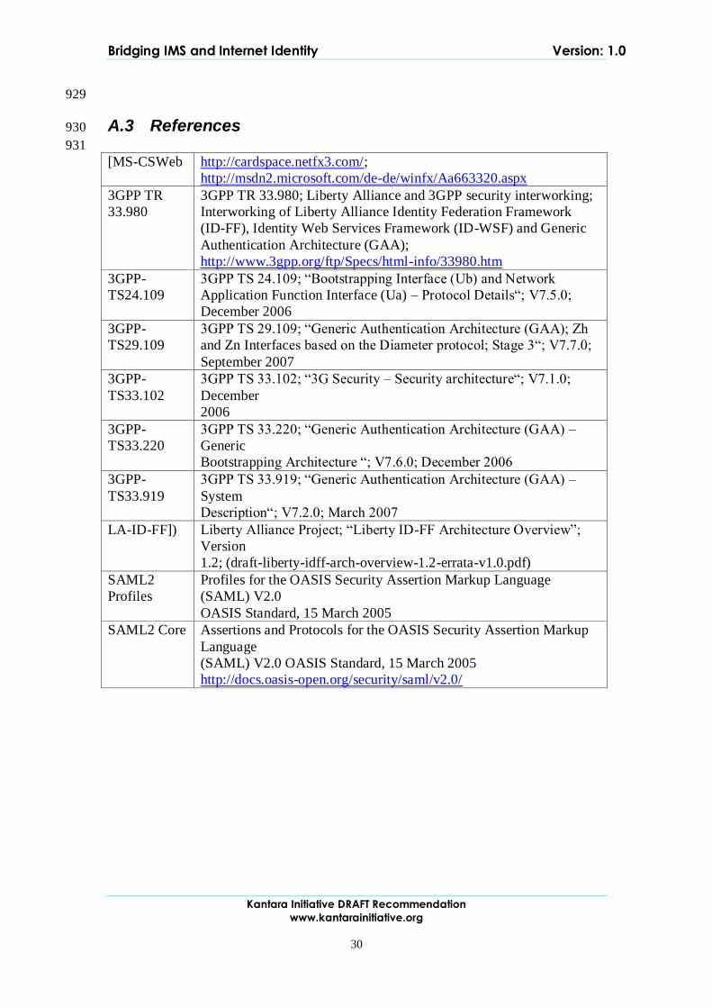
929
A.3 References 930
931
[MS-CSWeb http://cardspace.netfx3.com/;
http://msdn2.microsoft.com/de-de/winfx/Aa663320.aspx
3GPP TR
33.980
3GPP TR 33.980; Liberty Alliance and 3GPP security interworking;
Interworking of Liberty Alliance Identity Federation Framework
(ID-FF), Identity Web Services Framework (ID-WSF) and Generic
Authentication Architecture (GAA);
http://www.3gpp.org/ftp/Specs/html-info/33980.htm
3GPP-
TS24.109
3GPP TS 24.109; “Bootstrapping Interface (Ub) and Network
Application Function Interface (Ua) – Protocol Details“; V7.5.0;
December 2006
3GPP-
TS29.109
3GPP TS 29.109; “Generic Authentication Architecture (GAA); Zh
and Zn Interfaces based on the Diameter protocol; Stage 3“; V7.7.0;
September 2007
3GPP-
TS33.102
3GPP TS 33.102; “3G Security – Security architecture“; V7.1.0;
December
2006
3GPP-
TS33.220
3GPP TS 33.220; “Generic Authentication Architecture (GAA) –
Generic
Bootstrapping Architecture “; V7.6.0; December 2006
3GPP-
TS33.919
3GPP TS 33.919; “Generic Authentication Architecture (GAA) –
System
Description“; V7.2.0; March 2007
LA-ID-FF]) Liberty Alliance Project; “Liberty ID-FF Architecture Overview”;
Version
1.2; (draft-liberty-idff-arch-overview-1.2-errata-v1.0.pdf)
SAML2
Profiles
Profiles for the OASIS Security Assertion Markup Language
(SAML) V2.0
OASIS Standard, 15 March 2005
SAML2 Core Assertions and Protocols for the OASIS Security Assertion Markup
Language
(SAML) V2.0 OASIS Standard, 15 March 2005
http://docs.oasis-open.org/security/saml/v2.0/
Bridging IMS and Internet Identity Version: 1.0
31
932
B. Technical Annex "Authentication context sharing between 933
GBA and Web Client applications on UEs" 934
As described in “GBA & ID FF Interworking” [3GPP-TS33.980]., the reuse of the 935
network authentication for web-based services is a valuable asset of a Telco and an 936
important step to converged services. 937
3GPP GBA Bootstrapping procedure with the enhancement of Interworking of 938
SAML2 is being specified, while it assumes the tight relationship between GBA 939
Client and Web Client applications. 940
This (informative) chapter describes the possible ways to use the secure 941
SIM/USIM/ISIM based authentication mechanism for a wider set of applications. 942
The research leading to these results has received funding from the European 943 Community's Seventh Framework Programme (FP7/2007-2013) under grant 944 agreement n° 216647. 945
B.1 Injection of Authentication context in a form of Cookie to 946
Applications 947
In the case of “Using the GBA to access the 3GPP HSS as identity provider within the 948
Liberty Alliance ID-FF” as identified in “GBA & ID FF Interworking” [3GPP-949
TS33.980]., for Interworking of Liberty Alliance ID-FF with 3GPP GBA, GBA Client 950
and Web Client are considered as tightly coupled and sharing the authentication 951
context . However, there is a strong demand for the use of IMS based authentication 952
to a wider range of applications. Especially the support for the existing Web Clients 953
(so-called web browsers) is desired. 954
To allow Web applications to start LA ID-FF based access to SP upon a successful 955
GBA authentication, it is necessary to activate the cookie information conveying the 956
authentication context, which should be provided to the IdP when redirected to 957
retrieve the Authentication Assertion. The challenge here is how to activate such 958
cookie information in generic web browsers. Two options for providing the Web 959
applications with the cookie information are described in this document: 960
1. Passing the cookie information directly from GBA Client to Web Client 961
application 962
2. Providing the one-time URL to access to retrieve the cookie information from 963
IdP through network. 964
Option 1 might be preferable as the transfer can be locally done between two Clients. 965
However, not all the browsers expose such a functionality for plug-in to insert cookie 966
information offline. In that case, it is necessary to let a browser access to the IdP to 967
activate the cookie information to share the authentication context as Option 2. 968
Note in both cases, only the communication between servers and clients are based on 969
the well defined standardized procedure except the data returned from GBA servers, 970
while the communication between GBA Client and Web Client application is rather 971
abstract concept and the procedure shows one of the potential examples to achieve 972
direct passing of the cookie information and injection of the cookie information by 973
forcing the network access respectively. 974
Note in Figure 12 and Figure 13, IdP is described as a separate entity for the 975
convenience of description, while this procedure allows the deployments cases where 976
the IdP collocates either with BSF or NAF. 977
978

Bridging IMS and Internet Identity Version: 1.0
Kantara Initiative DRAFT Recommendation
www.kantarainitiative.org
32
B.1.1 Direct transfer of the cookie information between GBA Client 979
and Web Client 980
This option is to let the Web Client application to get the cookie information directly 981
from GBA Client belonging to the same user. GBA Client retrieves the cookie 982
information upon a successful GBA authentication and passes it to the Web Client. 983
Figure 12 shows the detail procedure: 984
1. GBA Client performs the authentication. 985
2. Along the NAF authentication process as a part of GBA authentication, 986
authentication context is shared with IdP. 987
3. IdP creates cookie information and returns it to NAF as a GBA server 988
component. 989
4. Upon a successful GBA authentication, the cookie information will be 990
returned to GBA Client to be shared with Web Client. 991
5. GBA Client registers this cookie information at Cookie registry. 992
6. When web client such as browser is invoked by the user, it access to the 993
cookie registry to fetch the cookie information for the IdP domain. 994
7. This cookie information will be provided in a request whenever the access is 995
redirected to the IdP. 996
Note Figure 13 shows the process with a client-side example where the component 997
called Cookie registry stores the cookie data GBA Client retrieves which then will be 998
fetched by the Web Client such as browser to be injected in its cookie manager upon a 999
starting up process. 1000 1001
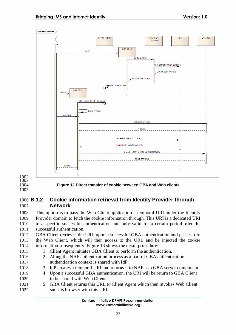
Bridging IMS and Internet Identity Version: 1.0
Kantara Initiative DRAFT Recommendation
www.kantarainitiative.org
33
1002 1003
Figure 12 Direct transfer of cookie between GBA and Web clients 1004 1005
B.1.2 Cookie information retrieval from Identity Provider through 1006
Network 1007
This option is to pass the Web Client application a temporal URI under the Identity 1008
Provider domain to fetch the cookie information through. This URI is a dedicated URI 1009
to a specific successful authentication and only valid for a certain period after the 1010
successful authentication. 1011
GBA Client retrieves the URL upon a successful GBA authentication and passes it to 1012
the Web Client, which will then access to the URL and be injected the cookie 1013
information subsequently. Figure 13 shows the detail procedure: 1014
1. Client Agent initiates GBA Client to perform the authentication. 1015
2. Along the NAF authentication process as a part of GBA authentication, 1016
authentication context is shared with IdP. 1017
3. IdP creates a temporal URI and returns it to NAF as a GBA server component. 1018
4. Upon a successful GBA authentication, the URI will be return to GBA Client 1019
to be shared with Web Client. 1020
5. GBA Client returns this URL to Client Agent which then invokes Web Client 1021
such as browser with this URI. 1022
Bridging IMS and Internet Identity Version: 1.0
Kantara Initiative DRAFT Recommendation
www.kantarainitiative.org
34
6. Web Client accesses to the URI under the IdP domain and fetch the cookie 1023
registry to fetch the cookie information for the IdP domain and store it its 1024
cookie manager. 1025
7. This cookie information will be provided in a request whenever the access is 1026
redirected to the IdP. 1027
1028 Figure 13: Cookie retrieval from Identity Provider 1029
1030
B.2 Consideration on Client deployment 1031
As the procedure described in this document does not assume tight coupling of GBA 1032
Client and Web Client, Web Client applications can be deployed on different devices 1033
than UE where GBA Client is installed. Examples of those devices are PC, TV, etc. 1034
nearby the UE, which belong to the same user as UE. Obviously, the interaction 1035
between Clients must be secured. The communication methods which allow the 1036
interaction only in certain proximity such as RFID can be considered as one of the 1037
ways to ensure the security. 1038
Bridging IMS and Internet Identity Version: 1.0
Kantara Initiative DRAFT Recommendation
www.kantarainitiative.org
35
B.3 The relationship with ID-WSF Advanced Client 1039
ID-WSF Advanced Client specifications define the provisioning mechanism. As this 1040
document focuses on the use of 3GPP GBA authentication context, the provisioning 1041
over the network as defined in ID-WSF Advance Client is out of scope. However, in 1042
the case of Option 1, the direct transfer of cookie information GBA Client to Web 1043
Client via Cookie registry, the communication among clients may be able to 1044
implement as a special case of the communication between RegApp and PM in ID-1045
WSF Advanced Client. Cookie registry can be considered as one of the functionalities 1046
of PM, which is activated by GBA Client as one of the RegApps, and then is got 1047
status by the enhanced Web Client as another RegApp. 1048
The necessity of such mapping as well as the preferable way of actual implementation is out 1049 of scope of this document. 1050
B.4 Conclusion 1051
The GBA is an authentication framework for 3G networks while Liberty Alliance ID-1052
FF is a framework for Web-based applications. The interworking of these two 1053
frameworks is already being specified but the enhancement is necessary to support a 1054
wider set of Web applications which may not be tightly coupled with the GBA client. 1055
In this document, the options for mechanisms to transfer the authentication context in 1056
a form of cookie are described. These mechanisms, together with additional secure 1057
data transfer mechanisms among on one or more devices belonging to the same user 1058
will enable a wider scope of applications to get the benefit of secure authentication 1059
mechanism provided GBA authentication. 1060 1061
1062

Bridging IMS and Internet Identity Version: 1.0
Kantara Initiative DRAFT Recommendation
www.kantarainitiative.org
36
C. Technical Annex : "SIP/SAML Messaging" 1063
C.1 Overview 1064
SAML is a set of protocol specifications that provide, among other things, seamless 1065
Single Sign-On (SSO) in a distributed environment where a user wishes to log into 1066
multiple Service Providers (SPs). In particular, once a user has authenticated towards 1067
a trusted entity called the IdP, the SAML protocols enable the IdP and the SPs to 1068
exchange information about the user's authentication status at the IdP in a secure 1069
manner and in a way that takes into account the user's privacy. Moreover, the SAML 1070
protocols enable the SPs and the IdP to exchange information about the user in the 1071
form of attributes. This feature is useful in the context of identity management 1072
systems that perform such attribute exchanges in an automated way, while enabling 1073
the user to exercise control over the dissemination of his personal information. 1074
1075
However, the SAML protocols are not self-contained in the sense that they require a 1076
transport mechanism. In particular, SAML messages need to be conveyed from one 1077
party to the other by some underlying transport protocol. The encoding of SAML 1078
messages in such transport protocols is called a SAML binding; multiple such 1079
bindings have been specified in the past. Examples are the HTTP REDIRECT 1080
binding, the HTTP POST binding, and the SOAP binding [SAMLBINDINGS]. To 1081
date, a SAML binding for SIP is still missing. 1082
1083
With each newly specified SAML profile and binding, the number and the diversity 1084
of applications and services that can interoperate with any given SAML-based IdP 1085
increases. This adds value to the overall system, because it enables the user to log 1086
into a larger and more diverse set of services in a seamless manner. Moreover, the 1087
number of services that can query the user's attributes from the IdP increases, 1088
resulting in a potentially more personalized experience for the user. 1089
1090
This section introduces the SIP/SAML profile. This profile can be used in a variety of 1091
situations, including the following. 1092
1093
The authentication provider (IdP) is a SIP proxy or an IMS entity, and it is 1094
necessary to convey authentication or attribute information to other SIP or 1095
IMS entities. 1096
The authentication provider (IdP) is a SIP proxy or an IMS entity, and it is 1097
necessary to convey authentication or attribute information to relying web 1098
services over HTTP. In this case, the SAML assertions may travel over SIP 1099
until the use equipment or some intermediate proxy, and are there 1100
encapsulated into HTTP messages. 1101
The authentication provider (IdP) is a web-based service provider, and it is 1102
necessary to convey authentication or attribute information to some SIP or 1103
IMS entity. In this case, the SAML assertions may travel over HTTP towards 1104
the user equipment or some intermediate proxy, and are there encapsulated 1105
into SIP messages. 1106
1107
Bridging IMS and Internet Identity Version: 1.0
Kantara Initiative DRAFT Recommendation
www.kantarainitiative.org
37
In the following, we outline two SIP SAML profiles, each with slightly different 1108
properties, but both consistent with existing HTTP SAML profiles. 1109
1110
C.2 Logical View 1111
C.2.1 Domain View 1112
Id Management
(Operator Domain)
IP Multimedia Subsystem
(Operator Domain)
3rd Party
Application Server
End
User
SIP
SIP
SAML
SIP
SAML
1113
Figure 14: Domain View 1114 1115
Note: the SAML interface between the end-user and the Id. Management system is 1116
included to complete the picture with existing interfaces and protocols, although this 1117
interface is not used in the scenarios presented later. 1118
3rd Party App. Server: The SP is hosted outside the operator‟s domain and 1119
the trust relationship with the operator is, generally, weak. This is the general 1120
broader scenarios, although it can also be applied when the App. Server 1121
belongs to the operator administrative domain, and the trust relationship is 1122
higher. 1123
Id Management: It is deployed inside the operator‟s domain and it handles 1124
the Identity Federation with other participants in the operator‟s Circle of Trust, 1125
and it offers functionality such as Single Sign-On (based on SAML) and 1126
Identity Services (based on ID-WSF protocol). 1127
IP Multimedia Subsystem: Contains the operator‟s infrastructure to offer 1128
IMS Services, including the IMS core network elements such as HSS. 1129
Bridging IMS and Internet Identity Version: 1.0
Kantara Initiative DRAFT Recommendation
www.kantarainitiative.org
38
C.3 SIP/SAML Direct Variant 1130
In this section, the Direct Variant of the SIP/SAML profile is specified. In the 1131
following, UA denotes the user agent (client), SP denotes a SIP Proxy, and Identity 1132
Provider denotes a SAML-based Identity Provider. This specification relies on a new 1133
SIP header, called the `SAML- Endpoint (SAML-EP)' header. This header contains a 1134
URI endpoint pointing to the 1135
user's SAML-based Identity Provider. 1136 1137
Figure 15: Direct Variant of the SIP/SAML Profile 1138 1139
Figure 15 shows the direct variant of the SAML/SIP profile in full i.e. where the user 1140
authenticates himself at the Identity Provider for the first time. It is assumed that all 1141
communication takes place over SIP; of course re-encapsulation over HTTP is 1142
possible (but not shown). The figure shows individual steps that occur during the 1143
protocol execution. With the exception of authentication, all the steps uniquely 1144

Bridging IMS and Internet Identity Version: 1.0
Kantara Initiative DRAFT Recommendation
www.kantarainitiative.org
39
correspond to a particular message that is exchanged in the corresponding step. In the 1145
following, we say `message X' in order to refer to the message that is exchanged in 1146
step X of the protocol. 1147
1148
First, the End-User constructs a SIP REGISTER message and sends it to the Service 1149
Provider (message 1). This message MUST contain one or more SAML-EP headers, 1150
where the value of each SAML-EP header MUST be one or more URIs. All the 1151
indicated URIs MUST belong to some SAML-based Identity Provider that is able to 1152
consume SIP REGISTER messages conforming to the format of message 3. The 1153
population of the SAML-EP header values is the responsibility of the End-User. If 1154
multiple SAML-EP header values are present in message 1 (either in the same or in 1155
multiple SAML-EP headers), then each URI within a SAML-EP header value MUST 1156
refer to a different Identity Provider. Also, each URI within a SAML-EP header 1157
value MUST refer to an Identity Provider where the user maintains an active account. 1158
However, there is no requirement to include more than Identity Provider URI, even if 1159
the user maintains accounts at multiple Identity Providers. Moreover, the order of the 1160
URIs within SAML-EP header values SHOULD reflect the user's preferences, most 1161
preferred first. That is, if the user prefers to be authenticated by Identity Provider A 1162
in preference to Identity Provider B, then the URI referring to Identity Provider A 1163
SHOULD be included in a SAML-EP header before the URI referring to Identity 1164
Provider B. 1165
1166
The following two possibilities exist when message 1 is received by the Service 1167
Provider. Case 1: the Service Provider does not support the SIP/SAML profile 1168
specified in this document. In this case, the SAML-EP header(s) are 1169
ignored, and the Service Provider responds 'normally', i.e. as in standard SIP. The 1170
End-User MUST be able to correctly handle a message conforming to standard SIP 1171
(instead of message 2 in Figure 15) as a response to message 1. Case 2: the Service 1172
Provider supports the SIP/SAML profile. In this case, it MUST examine the SAML-1173
EP headers and check whether or not an agreement exists with at least one of the 1174
indicated Identity Providers. If an agreement exists with at least one of them, then it 1175
MUST pick one of those with whom an agreement exists; the one it selects is denoted 1176
by SIDP. The Service Provider SHOULD select the Identity Provider that 1177
corresponds to the first URI within any SAML-EP header with whom an agreement 1178
exists. If no agreement consists with any of the IdPs then the Service Provider MUST 1179
act as if it does not support the SIP/SAML profile specified in this document, i.e. 1180
respond with a message conforming to 'standard' SIP. 1181
1182
After the SIDP has been selected, the Service Provider MUST decide with which 1183
SAML/ SIP profile it would like to proceed. This decision MAY be based on a policy 1184
or similar criteria. If the 'SIP Artifact' profile is selected, then the remainder of the 1185
processing and the protocol is as described in the next section. Otherwise, i.e. if the 1186
'direct' profile is selected, then processing continues as follows. 1187
1188
Message 2 is constructed as follows. The Service Provider constructs a SIP 302 1189
REDIRECT message where the value of the 'Contact' header is equal to the value of 1190
the SAML-EP header (from message 1) that corresponds to the SIDP. This value is 1191
Bridging IMS and Internet Identity Version: 1.0
Kantara Initiative DRAFT Recommendation
www.kantarainitiative.org
40
denoted by SIDP URI in Figure 7. Moreover, message 2 MUST contain a SAML 1192
Request, which MUST be constructed according to [SAML]. 1193
1194
Upon reception of message 2, the End-User SHOULD check that the SIDP URI 1195
indicated in the 'Connect' header is one of those proposed in message 1. If this is not 1196
the case, then the End-User MAY abort the protocol execution at this point. It also 1197
MAY inform the user about the inconsistency, and it MAY ask for the user's 1198
permission on whether to proceed with the given SIDP URI. It is RECOMMENDED 1199
that the End-User does not proceed with the protocol execution if the indicated SIDP 1200
URI is not one of the ones proposed in message 1, unless the user explicitly allows the 1201
protocol execution to continue. 1202
1203
After reception of message 2, the End-User MUST decide how to proceed in trying to 1204
obtain a SAML Response that matches the Service Provider's SAML Request in 1205
message 2. Multiple possibilities MAY exist for this, and this specification does not 1206
impose the End-User to use any particular method. However, if the End-User decides 1207
to continue with the `Direct Variant' of the SIP/SAML profile, then it MUST proceed 1208
as follows. 1209
1210
It constructs message 3 as a new SIP REGISTER message, which is sent to the SIDP 1211
URI. The message contains the SAML Request from message 2. Note that, since 1212
message 3 is sent to an Identity Provider (which may or may not be a SIP Proxy), its 1213
purpose it not to register at a SIP Proxy; its purpose is to trigger authentication at the 1214
Identity Provider. 1215
1216
In step 4 of the protocol, Identity Provider authenticates the user. This may involve 1217
multiple messages between the End-User and the Identity Provider. This specification 1218
does not impose any particular authentication mechanism. However, in order to 1219
guarantee minimal interoperability, the standard SIP user authentication mechanism 1220
(Digest Authentication, see section 22 of [RFC3261]) MUST be implemented at both 1221
the Identity Provider and the End-User. However, whether or not the Identity 1222
Provider will choose this method or some other method is dependent on policy. 1223
1224
After the authentication of the user towards the Identity Provider, the Identity 1225
Provider constructs message 5. This is a SIP 302 REDIRECT message where the 1226
'Contact' header MUST contain a value that is extracted from the SAML request in 3, 1227
according to [SAML]. According to [SAML], the SAML Response contains the 1228
description of an authentication context if the user's authentication in step 4 has been 1229
successful. If this is the case, the authentication context in the SAML Response 1230
MUST describe the user's authentication context that resulted from the authentication 1231
in step 4. 1232
1233
Finally, the End-User constructs a new SIP REGISTER message and sends this to the 1234
Service Provider in step 6. This SIP REGISTER message MUST contain the SAML 1235
Response from message 5. Upon reception of that message, the Service Provider 1236
MUST examine the SAML Response according to [SAML]. If the Service Provider 1237
Bridging IMS and Internet Identity Version: 1.0
Kantara Initiative DRAFT Recommendation
www.kantarainitiative.org
41
is satisfied, then the user is recorded as 'registered' in the SIP Proxy, and the 1238
remaining processing continues according to standard SIP [RFC3261]. 1239
1240
C.4 SIP/SAML Artifact Variant 1241
This section specifies the SIP-Artifact Variant of the SIP/SAML Profile. The main 1242
difference between the SIP-Artifact Variant and the Direct Variant is that, in the SIP-1243
Artifact Profile, the End-User cannot see the SAML messages that are exchanged 1244
between the Service Provider and the Identity Provider. Instead, the Service Provider 1245
and the Identity Provider exchange SAML messages directly. Special identifiers that 1246
identify individual SAML messages, called `SAML Artifacts' are tunneled through 1247
the End-User. 1248
1249
Figure 16 shows the SIP-Artifact variant of the SAML/SIP profile in full i.e. where 1250
the user authenticates himself at the Identity Provider for the first time. The figure 1251
shows individual steps that occur during the protocol execution. With the exception 1252
of steps 4, 5, and 8 all the steps uniquely correspond to a particular message that is 1253
exchanged in the corresponding step. In the following, we say `message X' in order to 1254
refer to the message that is exchanged in step X of the protocol. 1255
1256
First, the End-User constructs a SIP REGISTER message and sends it to the Service 1257
Provider (message 1). This message is constructed in a manner identical to the 1258
construction of the first message in the `direct' variant, as specified in the section 1259
above. The behavior of the Service Provider after having received message 1 is 1260
identical to the behavior specified for the `direct' variant in the section above, up to 1261
the point where the Service Provider decides which variant to use. If the Service 1262
Provider decides to use the `Artifact' variant, the processing is as follows. 1263
1264
The Service Provider MUST construct a SAML Artifact pointing to a SAML Request 1265
message for consumption by the SIDP, according to [SAML]. Message 2 is then 1266
constructed as a SIP 302 REDIRECT message, where the `Contact' header MUST 1267
take as value the URI indicated by the SAML- Endpoint header (from message 1) that 1268
corresponds to the SIDP, modified as follows. 1269
1270
Moreover, message 2 MUST contain exactly one SAML-EP header, where the value 1271
is the URI at which the Service Provider will accept a SAML Artifact Resolution 1272
request from the SIDP. 1273
1274
Upon reception of message 2, the End-User SHOULD check that the SIDP URI 1275
indicated in the 'Connect' header is one of those proposed in message 1. If this is not 1276
the case, then the End-User MAY abort the protocol execution at this point. It also 1277
MAY inform the user about the inconsistency, and it MAY ask for the user's 1278
permission on whether to proceed with the given SIDP URI. It is RECOMMENDED 1279
that the End-User does not proceed with the protocol execution if the indicated SIDP 1280
URI is does not correspond to any of those that were proposed in message 1, unless 1281
the user explicitly allows the protocol execution to continue. 1282
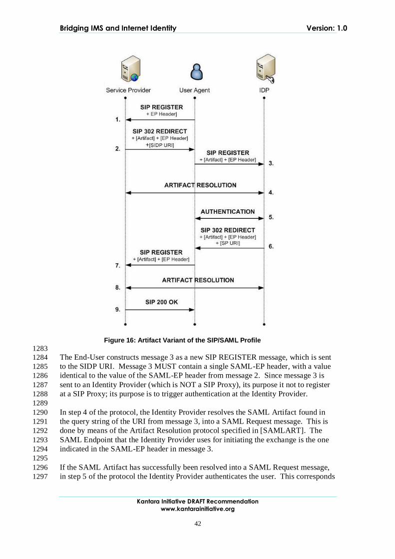
Bridging IMS and Internet Identity Version: 1.0
Kantara Initiative DRAFT Recommendation
www.kantarainitiative.org
42
1283
The End-User constructs message 3 as a new SIP REGISTER message, which is sent 1284
to the SIDP URI. Message 3 MUST contain a single SAML-EP header, with a value 1285
identical to the value of the SAML-EP header from message 2. Since message 3 is 1286
sent to an Identity Provider (which is NOT a SIP Proxy), its purpose it not to register 1287
at a SIP Proxy; its purpose is to trigger authentication at the Identity Provider. 1288
1289
In step 4 of the protocol, the Identity Provider resolves the SAML Artifact found in 1290
the query string of the URI from message 3, into a SAML Request message. This is 1291
done by means of the Artifact Resolution protocol specified in [SAMLART]. The 1292
SAML Endpoint that the Identity Provider uses for initiating the exchange is the one 1293
indicated in the SAML-EP header in message 3. 1294
1295
If the SAML Artifact has successfully been resolved into a SAML Request message, 1296
in step 5 of the protocol the Identity Provider authenticates the user. This corresponds 1297
Figure 16: Artifact Variant of the SIP/SAML Profile
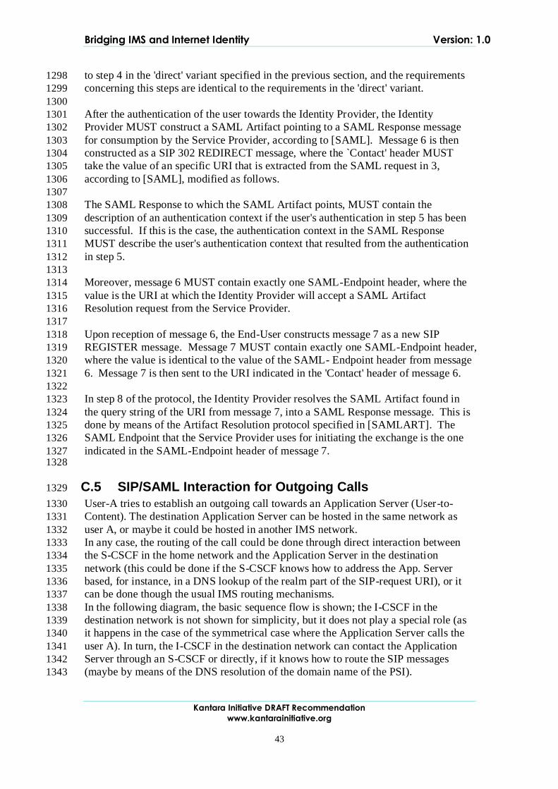
Bridging IMS and Internet Identity Version: 1.0
Kantara Initiative DRAFT Recommendation
www.kantarainitiative.org
43
to step 4 in the 'direct' variant specified in the previous section, and the requirements 1298
concerning this steps are identical to the requirements in the 'direct' variant. 1299
1300
After the authentication of the user towards the Identity Provider, the Identity 1301
Provider MUST construct a SAML Artifact pointing to a SAML Response message 1302
for consumption by the Service Provider, according to [SAML]. Message 6 is then 1303
constructed as a SIP 302 REDIRECT message, where the `Contact' header MUST 1304
take the value of an specific URI that is extracted from the SAML request in 3, 1305
according to [SAML], modified as follows. 1306
1307
The SAML Response to which the SAML Artifact points, MUST contain the 1308
description of an authentication context if the user's authentication in step 5 has been 1309
successful. If this is the case, the authentication context in the SAML Response 1310
MUST describe the user's authentication context that resulted from the authentication 1311
in step 5. 1312
1313
Moreover, message 6 MUST contain exactly one SAML-Endpoint header, where the 1314
value is the URI at which the Identity Provider will accept a SAML Artifact 1315
Resolution request from the Service Provider. 1316
1317
Upon reception of message 6, the End-User constructs message 7 as a new SIP 1318
REGISTER message. Message 7 MUST contain exactly one SAML-Endpoint header, 1319
where the value is identical to the value of the SAML- Endpoint header from message 1320
6. Message 7 is then sent to the URI indicated in the 'Contact' header of message 6. 1321
1322
In step 8 of the protocol, the Identity Provider resolves the SAML Artifact found in 1323
the query string of the URI from message 7, into a SAML Response message. This is 1324
done by means of the Artifact Resolution protocol specified in [SAMLART]. The 1325
SAML Endpoint that the Service Provider uses for initiating the exchange is the one 1326
indicated in the SAML-Endpoint header of message 7. 1327 1328
C.5 SIP/SAML Interaction for Outgoing Calls 1329
User-A tries to establish an outgoing call towards an Application Server (User-to-1330
Content). The destination Application Server can be hosted in the same network as 1331
user A, or maybe it could be hosted in another IMS network. 1332
In any case, the routing of the call could be done through direct interaction between 1333
the S-CSCF in the home network and the Application Server in the destination 1334
network (this could be done if the S-CSCF knows how to address the App. Server 1335
based, for instance, in a DNS lookup of the realm part of the SIP-request URI), or it 1336
can be done though the usual IMS routing mechanisms. 1337
In the following diagram, the basic sequence flow is shown; the I-CSCF in the 1338
destination network is not shown for simplicity, but it does not play a special role (as 1339
it happens in the case of the symmetrical case where the Application Server calls the 1340
user A). In turn, the I-CSCF in the destination network can contact the Application 1341
Server through an S-CSCF or directly, if it knows how to route the SIP messages 1342
(maybe by means of the DNS resolution of the domain name of the PSI). 1343
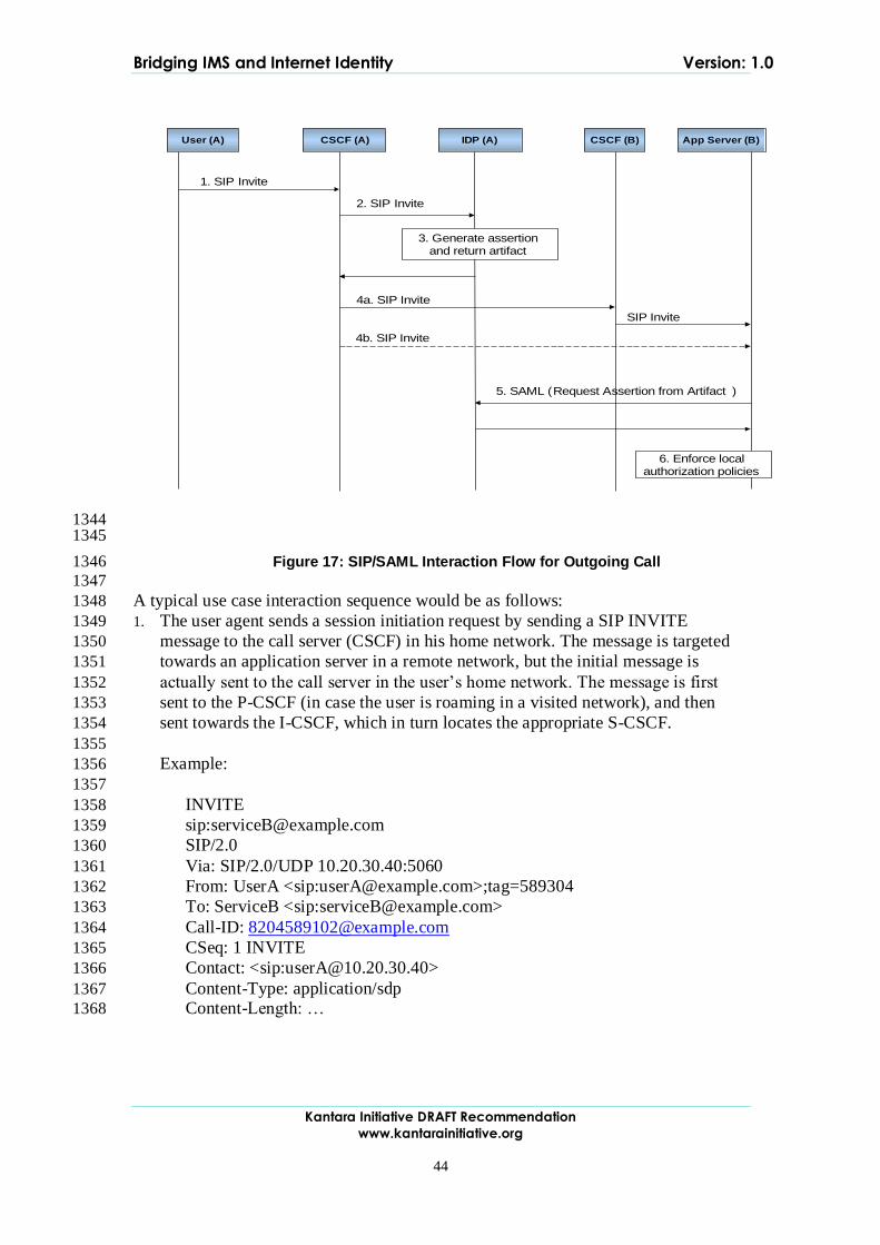
Bridging IMS and Internet Identity Version: 1.0
Kantara Initiative DRAFT Recommendation
www.kantarainitiative.org
44
User (A) CSCF (A) IDP (A) CSCF (B) App Server (B)
1. SIP Invite
4a. SIP Invite
SIP Invite
2. SIP Invite
3. Generate assertionand return artifact
5. SAML (Request Assertion from Artifact )
6. Enforce localauthorization policies
4b. SIP Invite
1344 1345
Figure 17: SIP/SAML Interaction Flow for Outgoing Call 1346
1347
A typical use case interaction sequence would be as follows: 1348
1. The user agent sends a session initiation request by sending a SIP INVITE 1349
message to the call server (CSCF) in his home network. The message is targeted 1350
towards an application server in a remote network, but the initial message is 1351
actually sent to the call server in the user‟s home network. The message is first 1352
sent to the P-CSCF (in case the user is roaming in a visited network), and then 1353
sent towards the I-CSCF, which in turn locates the appropriate S-CSCF. 1354
1355
Example: 1356
1357
INVITE 1358
sip:[email protected] 1359
SIP/2.0 1360
Via: SIP/2.0/UDP 10.20.30.40:5060 1361
From: UserA <sip:[email protected]>;tag=589304 1362
To: ServiceB <sip:[email protected]> 1363
Call-ID: [email protected] 1364
CSeq: 1 INVITE 1365
Contact: <sip:[email protected]> 1366
Content-Type: application/sdp 1367
Content-Length: … 1368
Bridging IMS and Internet Identity Version: 1.0
Kantara Initiative DRAFT Recommendation
www.kantarainitiative.org
45
2. The S-CSCF checks that there is a trigger defined for those messages directed to 1369
that specific application server, and therefore, sends the message to the Id. Server, 1370
via the ISC interface. In this scenario, the Id. Server is acting as another 1371
application server, from the point of view of the S-CSCF. 1372
1373
It must be noted that if there are several Application Servers connected with the S-1374
CSCF through the ISC interface, it must be necessary to process the different 1375
triggers in an appropriate order because, once the public identities are converted to 1376
federated shared identities, they will become useless to the remaining Application 1377
Servers. Therefore, the translation of user identities to federated alias must be the 1378
last thing to be done before the SIP message leaves the operator‟s home network. 1379
3. The Id. Sever generates a SAML assertion according to the security and identity 1380
information regarding user A. This assertion may contain authentication 1381
information, user attributes, specific access control and authorization information, 1382
etc… The assertion is referenced by a small piece of data called “artifact”. Either 1383
the full assertion or the artifact will be returned to the CSCF inserted in a specific 1384
header of the SIP message (for instance, in the “Identity” header). 1385
1386
It must be pointed out that this behavior does not follow the traditional Request-1387
Response procedures defined for SAML, since the assertion are generated by the 1388
Id. Server without being requested (i.e., there is not an incoming SAML 1389
Authentication Request message to trigger the generation of the SAML assertion). 1390
If anything, it could resemble to the behavior of the Unsolicited Authentication 1391
Request mechanism. 1392
1393
Note that the assertion will include the identity of the user A, but properly 1394
qualified for the targeted Application Server. This means that, if user A holds a 1395
federated identity relationship with that Application Server, then the shared 1396
federated identity (alias) will be included as the user identity towards the 1397
Application Server. 1398
1399
Before returning the SIP message to the S-CSCF, the alias must be properly 1400
qualified with a domain name associated to a Public Service Identifier (PSI) 1401
associated with the Identity Server itself. This must be done like this to allow the 1402
I-CSCF to process an eventual incoming call received from the remote 1403
Application Server, as will be explained in the next use case. 1404
1405
In case the identity token employed in the Identity header is an artifact, the PSI 1406
domain name of the Identity Server is not needed, since the artifact itself includes 1407
the Id. of the issuer (the Id. Server). 1408
1409
Note that the artifact must be appropriately formatted when it is included in the 1410
Identity header, to conform to the “URI-style” content (i.e., special chars must be 1411
formatted with the “%xx” notation). 1412
1413
Example: 1414
Bridging IMS and Internet Identity Version: 1.0
Kantara Initiative DRAFT Recommendation
www.kantarainitiative.org
46
INVITE 1415
sip:[email protected] 1416
SIP/2.0 1417
Via: SIP/2.0/UDP 10.20.30.40:5060 1418
From: “Anonymous” 1419
<sip:[email protected]>;tag=589304 1420
To: “ServiceB” <sip:[email protected]> 1421
Identity: 1422
AAQAADWNEw5VT47wcO4zX%2FiEzMmFQvGknDfws2ZtqSG1423
dkNSbsW1cmVR0bzU%3D 1424
Call-ID: [email protected] 1425
CSeq: 1 INVITE 1426
Contact: <sip:[email protected]> (Removed) 1427
Content-Type: application/sdp 1428
Content-Length: … 1429
1430
4. The CSCF receives the modified SIP message and forwards it to the destination 1431
application server. This server could be located in the same network as the Id. 1432
Server and CSCF, or it could be located in a remote IMS network. Therefore, the 1433
Application Server can be contacted directly from the CSCF (if the CSCF knows 1434
how to address it), or maybe it is necessary to contact first the I/S-CSCF‟s of the 1435
remote network, in order to reach the Application Server. Both alternatives are 1436
considered as feasible. 1437
5. When the SIP INVITE message reaches the Application Server, it extracts the 1438
identity information from the specific SIP header (“Identity”), and if the identity is 1439
found to be in the format of a SAML artifact, it must retrieve the original SAML 1440
assertion generated previously by the Id. Server. To do that, the Application 1441
Server issues a SAML Request (using for instance a SOAP request) to retrieve the 1442
full assertion. The SOAP end-point of the Id. Server must be known in advance by 1443
the Application Server and this is typically configuration data exchanged out-of-1444
band. 1445
1446
Note that the assertion could have been fully delivered in the SIP message, and in 1447
this case, the App. Server does not need to contact the Identity Server to resolve 1448
the artifact into the full assertion. 1449
Example: 1450
Request 1451
POST /SAML/Artifact/Resolve HTTP/1.1 1452
Host: IdentityProvider.com 1453
Content-Type: text/xml 1454
Content-Length: … 1455
SOAPAction: http://www.oasis-open.org/committees/security 1456
<SOAP-ENV:Envelope 1457
Bridging IMS and Internet Identity Version: 1.0
Kantara Initiative DRAFT Recommendation
www.kantarainitiative.org
47
xmlns:SOAP-ENV="http://schemas.xmlsoap.org/soap/envelope/"> 1458
<SOAP-ENV:Body> 1459
<samlp:ArtifactResolve 1460
xmlns:samlp="urn:oasis:names:tc:SAML:2.0:protocol" 1461
xmlns="urn:oasis:names:tc:SAML:2.0:assertion" 1462
ID="_6c3a4f8b9c2d" Version="2.0" 1463
IssueInstant="2004-01-21T19:00:49Z"> 1464
<Issuer>https://serviceB.example.com/SAML</Issuer> 1465
<Artifact> 1466
AAQAADWNEw5VT47wcO4zX/iEzMmFQvGknDfws2ZtqSGdkN1467
SbsW1cmVR0bzU= 1468
</Artifact> 1469
</samlp:ArtifactResolve> 1470
</SOAP-ENV:Body> 1471
</SOAP-ENV:Envelope> 1472
Response 1473
HTTP/1.1 200 OK 1474
Date: 21 Jan 2004 07:00:49 GMT 1475
Content-Type: text/xml 1476
Content-Length: … 1477
<SOAP-ENV:Envelope 1478
xmlns:SOAP-ENV="http://schemas.xmlsoap.org/soap/envelope/"> 1479
<SOAP-ENV:Body> 1480
<samlp:ArtifactResponse 1481
xmlns:samlp="urn:oasis:names:tc:SAML:2.0:protocol" 1482
xmlns="urn:oasis:names:tc:SAML:2.0:assertion" 1483
ID="_FQvGknDfws2Z" Version="2.0" 1484
InResponseTo="_6c3a4f8b9c2d" 1485
IssueInstant="2004-01-21T19:00:49Z"> 1486
<Issuer>https://ids.example.com/</Issuer> 1487
<samlp:Status> 1488
<samlp:StatusCode 1489
Value="urn:oasis:names:tc:SAML:2.0:status:Success"/> 1490
</samlp:Status> 1491
<samlp:AuthnResponse ID="d2b7c388cec36fa7c39c28fd298644a8" 1492
IssueInstant="2004-01-21T19:00:49Z" 1493
Version="2.0"> 1494
<Issuer>https://IdentityProvider.com/SAML</Issuer> 1495
<NameID Format="urn:oasis:names:tc:SAML:2.0:nameidformat: 1496
persistent">[email protected]</NameID> 1497
1498
(…) 1499
1500
</samlp:AuthnResponse> 1501
</samlp:ArtifactResponse> 1502
</SOAP-ENV:Body> 1503

Bridging IMS and Internet Identity Version: 1.0
Kantara Initiative DRAFT Recommendation
www.kantarainitiative.org
48
</SOAP-ENV:Envelope> 1504
1505
6. Once the assertion has been delivered by the Id. Server, the Application Server 1506
can inspect the user identity included in the assertion (it could be the real public 1507
identity, IMPU, of the user A, or an alias if privacy issues are a concern towards 1508
this specific Application Server). Additional access control policies can be 1509
enforced by the AS according to the information and attributes received in the 1510
SAML assertion from the Id. Server. 1511
1512
C.6 SIP/SAML Interaction for Incoming Calls 1513
The Application Server tries to establish an outgoing call towards user A (Content-to-1514
User). The Application Server can be hosted in the same network as user A, or maybe 1515
it could be hosted in another IMS network. 1516
It is assumed that there is an existing relationship (federation) between the user and 1517
the Application Server. This federation could have happened through different 1518
channels (for instance, web-based service registration and federation). 1519
The routing of the call could be done through direct interaction between the S-CSCF 1520
in the home network of the Application Server and the I-CSCF of the home network 1521
of user A, or it can be done though the usual IMS routing mechanisms (contacting 1522
first the local S-CSCF in the home network of the Application Server). 1523
In the following diagram, the basic sequence flow is shown; the I-CSCF in the home 1524
network of user A receives an aliased identifier which is invalid for routing purposes, 1525
so it must be resolved to a valid IMS identifier before the call routing can take place. 1526
The proposed flow would be as follows: 1527
User (A) I-CSCF (A)IDP (A) CSCF (B) App Server (B)
1a. SIP Invite (alias)
SIP Invite
S-CSCF (A)
1b. SIP Invite (alias)
3. SIP Invite (terminated at IdP)
7. SIP Invite
8. SIP Invite
6. Route incoming callaccording to identity of user A
4. Map alias toidentity of user A
2. Extract PSI from alias
5. SIP Invite (initiated at IdP)
1528
Figure 18: SIP/SAML Interaction Flow for Incoming Call 1529 1530
Bridging IMS and Internet Identity Version: 1.0
Kantara Initiative DRAFT Recommendation
www.kantarainitiative.org
49
The interaction sequence would be as follows: 1531
The Application Server sends a session initiation request by sending a SIP INVITE 1532
message targeted to the user A. This user might be known at the Application Server 1533
by its public identity (IMPU) or maybe by an alias shared with the Id. Server in its 1534
home network. In both cases, the Application Server should contact the call server of 1535
the user A home network; this can be done establishing a direct connection to the I-1536
CSCF (if the Application Server is able to locate it), or maybe making use of the 1537
CSCF in its own network. Both are considered as feasible alternatives. 1538
1539
Example: 1540 1541
INVITE 1542
sip:[email protected] 1543 SIP/2.0 1544 Via: SIP/2.0/UDP 10.20.30.40:5060 1545 From: ServiceB <sip:Service [email protected]>;tag=589304 1546 To: UserA <sip:[email protected]> 1547 Call-ID: [email protected] 1548 CSeq: 1 INVITE 1549 Content-Type: application/sdp 1550 Content-Length: … 1551
1. In the home network of user A, the I-CSCF receives the SIP INVITE message. It 1552
must be able to route the message to the appropriate S-CSCF. In order to do that, 1553
the real IMPU of user A must be known, and therefore, if an alias was received 1554
from the Application Server, it must be first de-referenced to the real user identity. 1555
This is achieved by relaying the SIP message to the Id. Server. 1556
2. Since there is no ISC interface defined between I-CSCF and an Application 1557
Server, a different mechanism must be defined to contact the Id. Server. The 1558
proposal is basically to define a Public Service Identifier (PSI) associated to the 1559
Id. Server, and make the I-CSCF extract the PSI from the identity received from 1560
the Application Server in the request URI of the SIP message (extracted from the 1561
domain name of the URI). 1562
1563
Obviously, the I-CSCF must have been configured with this PSI and the aliased 1564
identity must have been composed by appending the PSI domain name to the 1565
federated shared alias between the Id. Server and the Application Server. 1566
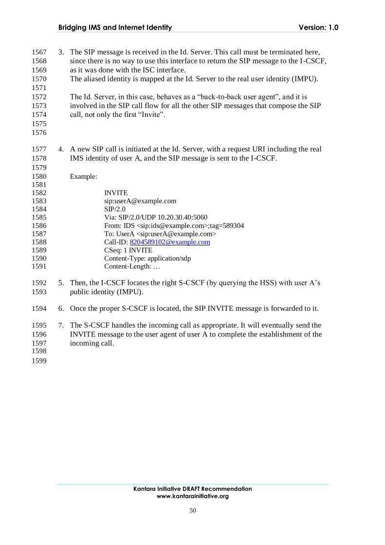
Bridging IMS and Internet Identity Version: 1.0
Kantara Initiative DRAFT Recommendation
www.kantarainitiative.org
50
3. The SIP message is received in the Id. Server. This call must be terminated here, 1567
since there is no way to use this interface to return the SIP message to the I-CSCF, 1568
as it was done with the ISC interface. 1569
The aliased identity is mapped at the Id. Server to the real user identity (IMPU). 1570
1571
The Id. Server, in this case, behaves as a “back-to-back user agent”, and it is 1572
involved in the SIP call flow for all the other SIP messages that compose the SIP 1573
call, not only the first “Invite”. 1574
1575
1576
4. A new SIP call is initiated at the Id. Server, with a request URI including the real 1577
IMS identity of user A, and the SIP message is sent to the I-CSCF. 1578
1579
Example: 1580 1581
INVITE 1582 sip:[email protected] 1583 SIP/2.0 1584 Via: SIP/2.0/UDP 10.20.30.40:5060 1585
From: IDS <sip:[email protected]>;tag=589304 1586 To: UserA <sip:[email protected]> 1587 Call-ID: [email protected] 1588 CSeq: 1 INVITE 1589 Content-Type: application/sdp 1590 Content-Length: … 1591
5. Then, the I-CSCF locates the right S-CSCF (by querying the HSS) with user A‟s 1592
public identity (IMPU). 1593
6. Once the proper S-CSCF is located, the SIP INVITE message is forwarded to it. 1594
7. The S-CSCF handles the incoming call as appropriate. It will eventually send the 1595
INVITE message to the user agent of user A to complete the establishment of the 1596
incoming call. 1597 1598
1599
Bridging IMS and Internet Identity Version: 1.0
Kantara Initiative DRAFT Recommendation
www.kantarainitiative.org
51
D. Technical Annex: "Liberty ID-WSF and IMS inter-working" 1600
This annex gives more technical details on how IMS Application Servers could 1601
integrate with the Liberty ID-WSF framework considering two generic use-cases: 1602
An IMS Application Server is acting as a Liberty ID-WSF Web Service 1603
Consumer in order to consume resources exposed through the ID-WSF 1604
framework. 1605
An IMS Application Server acting as a Liberty ID-WSF Web Service Provider 1606
in order to expose IMS resources through the ID-WSF framework. 1607 1608
D.1 IMS Application Server as a Liberty ID-WSF WSC 1609
This use-case is an extension of the "SIP/SAML Interaction for Outgoing Calls" case 1610
(see Technical Annex : "SIP/SAML Messaging"). 1611
User-A tries to establish an outgoing call towards an Application Server (User-to-1612
Content). And in this use-case, the destination Application Server needs to retrieve 1613
data associated to User-A to fulfill the service. These data are exposed by an ID-WSF 1614
WSP that can be discovered through the ID-WSF Discovery Service. 1615 1616 1617
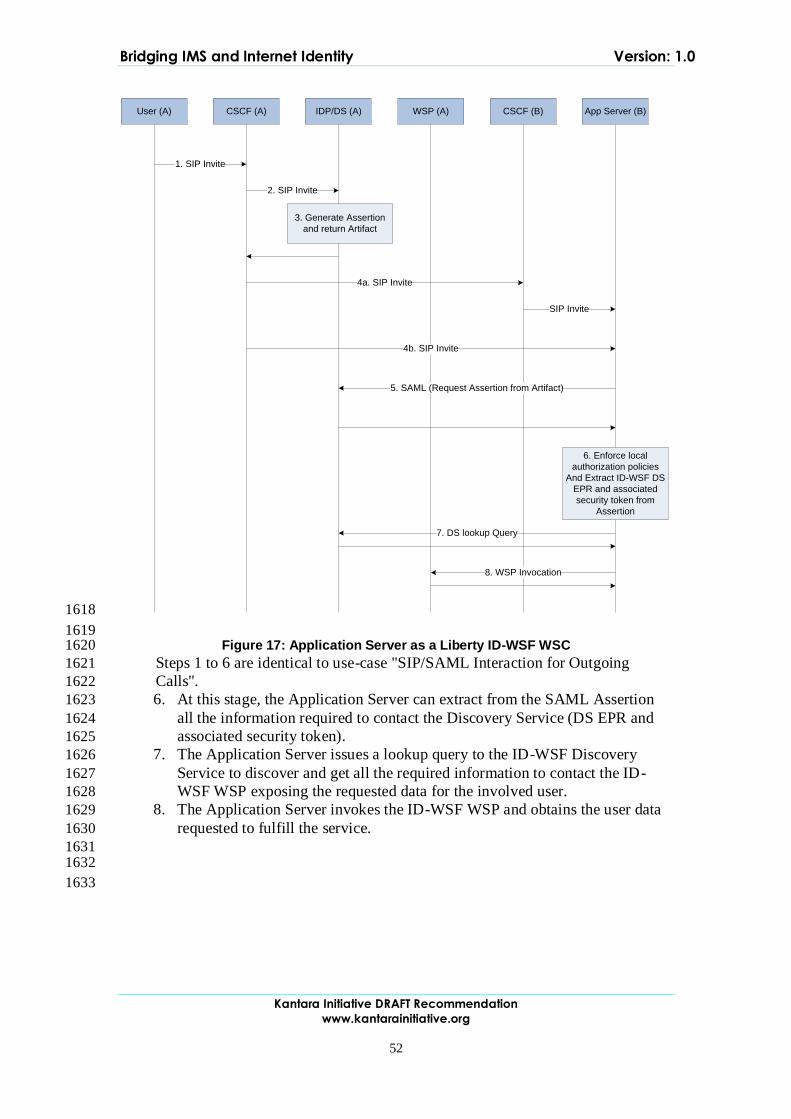
Bridging IMS and Internet Identity Version: 1.0
Kantara Initiative DRAFT Recommendation
www.kantarainitiative.org
52
User (A) CSCF (A) IDP/DS (A) CSCF (B) App Server (B)WSP (A)
1. SIP Invite
2. SIP Invite
3. Generate Assertion
and return Artifact
4a. SIP Invite
SIP Invite
4b. SIP Invite
5. SAML (Request Assertion from Artifact)
6. Enforce local
authorization policies
And Extract ID-WSF DS
EPR and associated
security token from
Assertion
7. DS lookup Query
8. WSP Invocation
1618
1619 Figure 17: Application Server as a Liberty ID-WSF WSC 1620
Steps 1 to 6 are identical to use-case "SIP/SAML Interaction for Outgoing 1621
Calls". 1622
6. At this stage, the Application Server can extract from the SAML Assertion 1623
all the information required to contact the Discovery Service (DS EPR and 1624
associated security token). 1625
7. The Application Server issues a lookup query to the ID-WSF Discovery 1626
Service to discover and get all the required information to contact the ID-1627
WSF WSP exposing the requested data for the involved user. 1628
8. The Application Server invokes the ID-WSF WSP and obtains the user data 1629
requested to fulfill the service. 1630
1631 1632
1633
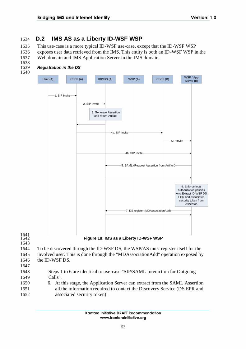
Bridging IMS and Internet Identity Version: 1.0
Kantara Initiative DRAFT Recommendation
www.kantarainitiative.org
53
D.2 IMS AS as a Liberty ID-WSF WSP 1634
This use-case is a more typical ID-WSF use-case, except that the ID-WSF WSP 1635
exposes user data retrieved from the IMS. This entity is both an ID-WSF WSP in the 1636
Web domain and IMS Application Server in the IMS domain. 1637 1638 Registration in the DS 1639 1640
User (A) CSCF (A) IDP/DS (A) CSCF (B)WSP / App
Server (B)WSP (A)
1. SIP Invite
2. SIP Invite
3. Generate Assertion
and return Artifact
4a. SIP Invite
SIP Invite
4b. SIP Invite
5. SAML (Request Assertion from Artifact)
6. Enforce local
authorization policies
And Extract ID-WSF DS
EPR and associated
security token from
Assertion
7. DS register (MDAssociationAdd)
1641 Figure 18: IMS as a Liberty ID-WSF WSP 1642
1643
To be discovered through the ID-WSF DS, the WSP/AS must register itself for the 1644
involved user. This is done through the "MDAssociationAdd" operation exposed by 1645
the ID-WSF DS. 1646
1647
Steps 1 to 6 are identical to use-case "SIP/SAML Interaction for Outgoing 1648
Calls". 1649
6. At this stage, the Application Server can extract from the SAML Assertion 1650
all the information required to contact the Discovery Service (DS EPR and 1651
associated security token). 1652
Bridging IMS and Internet Identity Version: 1.0
Kantara Initiative DRAFT Recommendation
www.kantarainitiative.org
54
7. The Application Server issues an "MDAssociationAdd" request to the ID-1653
WSF Discovery Service to register itself as an ID-WSF WSP for the 1654
involved user. The WSP / AS can now be discovered for that user. 1655 1656
1657
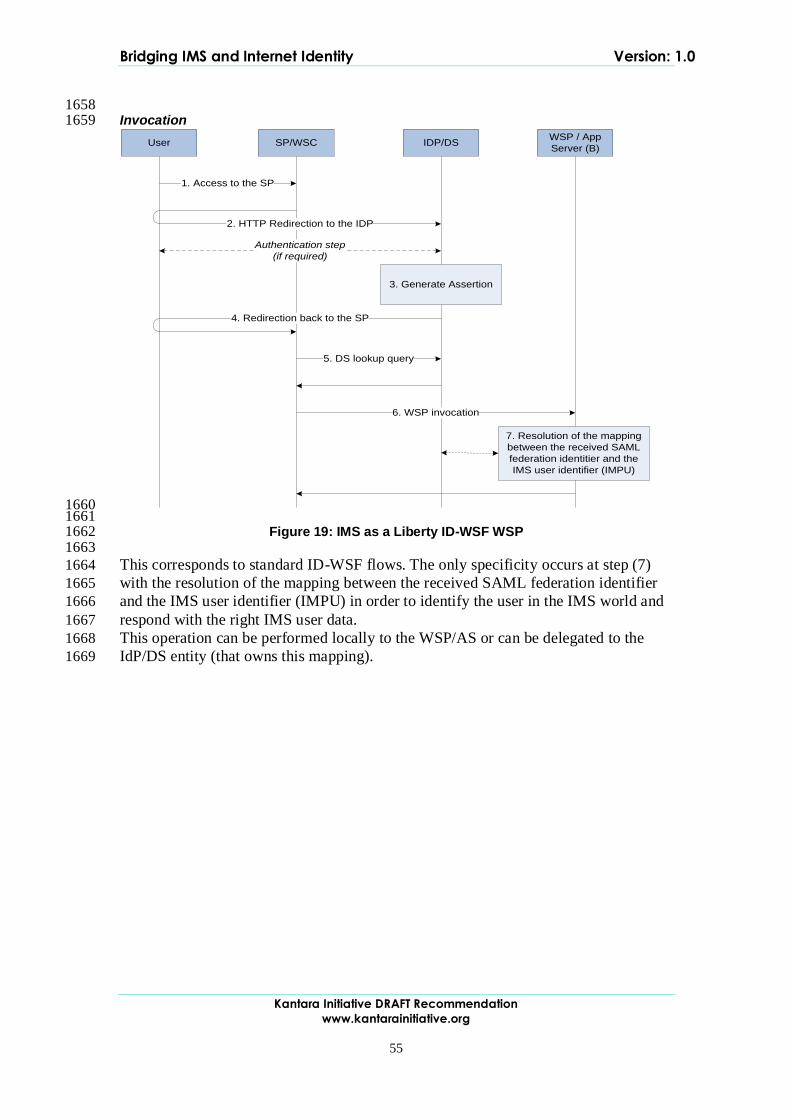
Bridging IMS and Internet Identity Version: 1.0
Kantara Initiative DRAFT Recommendation
www.kantarainitiative.org
55
1658 Invocation 1659
User SP/WSC IDP/DSWSP / App
Server (B)
1. Access to the SP
2. HTTP Redirection to the IDP
Authentication step
(if required)
4. Redirection back to the SP
5. DS lookup query
6. WSP invocation
3. Generate Assertion
7. Resolution of the mapping
between the received SAML
federation identitier and the
IMS user identifier (IMPU)
1660 1661
Figure 19: IMS as a Liberty ID-WSF WSP 1662 1663
This corresponds to standard ID-WSF flows. The only specificity occurs at step (7) 1664
with the resolution of the mapping between the received SAML federation identifier 1665
and the IMS user identifier (IMPU) in order to identify the user in the IMS world and 1666
respond with the right IMS user data. 1667
This operation can be performed locally to the WSP/AS or can be delegated to the 1668
IdP/DS entity (that owns this mapping). 1669