Bridge Standards and Procedures Manual - Volume 1 - · PDF fileSection 10 Steel structures...
22
Supplement to CHBDC S6-14 Section 10 Steel structures October 28 2016 -1- BC MoTI 10.4 MATERIALS ................................................................................................................... 2 10.4.1 General .................................................................................................................. 2 10.4.2 Structural steel ....................................................................................................... 2 10.4.5 Bolts ....................................................................................................................... 4 10.4.7 Stud shear connectors........................................................................................... 5 10.4.10 Galvanizing and metallizing ................................................................................... 5 10.4.13 Pins and rollers ...................................................................................................... 5 10.6 DURABILITY .................................................................................................................. 5 10.6.3 Corrosion protection .............................................................................................. 5 10.6.4 Superstructure components .................................................................................. 6 10.6.4.2 Structural steel ....................................................................................................... 6 10.6.4.3 Cables, ropes, and strands.................................................................................... 7 10.6.5 Other components ................................................................................................. 7 10.7 DESIGN DETAILS.......................................................................................................... 7 10.7.1 General .................................................................................................................. 7 10.7.1.1 Flange widths between splices .............................................................................. 8 10.7.1.2 Transition of flange thicknesses at butt welds ....................................................... 8 10.7.1.3 Recommended details ........................................................................................... 9 10.7.1.3.1 Coping of stiffeners and gusset plates .................................................................. 9 10.7.1.3.2 Gusset plates for lateral bracing .......................................................................... 10 10.7.1.3.3 Frames for lateral bracing, cross-frames and diaphragms.................................. 10 10.7.1.3.4 Box girder diaphragm bracing ............................................................................. 12 10.7.1.3.5 Intermediate diaphragms in shallow girders ........................................................ 12 10.7.1.3.6 Box girder diaphragms at piers and abutments................................................... 12 10.7.1.3.7 Transitions of box girder flange and web thicknesses ........................................ 13 10.7.1.3.8 Grinding of butt welds .......................................................................................... 14 10.7.1.3.9 Vertical stiffeners ................................................................................................. 15 10.7.1.3.10 Bearing stiffener to flange connection ................................................................. 15 10.7.1.3.11 Intermediate stiffener to flange connection ......................................................... 16 10.7.1.3.12 Stiffener to web connection ................................................................................. 17 10.7.1.3.13 Intersecting longitudinal and transverse stiffeners .............................................. 17 10.7.1.3.14 Box girder intermediate web stiffeners ................................................................ 18 10.7.1.3.15 Box girder bottom flange stiffener details ............................................................ 18 10.7.4 Camber ................................................................................................................ 19 10.7.4.1 Design.................................................................................................................. 19 10.18 SPLICES AND CONNECTIONS ............................................................................. 20 10.18.1 General ................................................................................................................ 20 10.18.3 Welds ................................................................................................................... 20 10.18.3.1 General ................................................................................................................ 20 10.19 ANCHOR RODS ...................................................................................................... 21 10.19.1 General ................................................................................................................ 21 10.23 FRACTURE CONTROL ........................................................................................... 21 10.23.3 Fracture toughness.............................................................................................. 21 10.23.3.3 Fracture-critical members .................................................................................... 21 A10.1 CONSTRUCTION REQUIREMENTS FOR STRUCTURAL STEEL ....................... 22 A10.1.1 General ................................................................................................................ 22 A10.1.5 Welded construction ............................................................................................ 22 A10.1.5.1 General ................................................................................................................ 22 A10.1.6 Bolted construction .............................................................................................. 22 A10.1.6.4 Installation of bolts ............................................................................................... 22 A10.1.8.2 Non-destructive testing of welds ......................................................................... 22
Transcript of Bridge Standards and Procedures Manual - Volume 1 - · PDF fileSection 10 Steel structures...
Supplement to CHBDC S6-14
Section 10 Steel structures
October 28 2016 -1- BC MoTI
10.4 MATERIALS ................................................................................................................... 2 10.4.1 General .................................................................................................................. 2 10.4.2 Structural steel ....................................................................................................... 2 10.4.5 Bolts ....................................................................................................................... 4 10.4.7 Stud shear connectors ........................................................................................... 5 10.4.10 Galvanizing and metallizing ................................................................................... 5 10.4.13 Pins and rollers ...................................................................................................... 5
10.6 DURABILITY .................................................................................................................. 5 10.6.3 Corrosion protection .............................................................................................. 5 10.6.4 Superstructure components .................................................................................. 6
10.6.4.2 Structural steel ....................................................................................................... 6 10.6.4.3 Cables, ropes, and strands.................................................................................... 7
10.6.5 Other components ................................................................................................. 7 10.7 DESIGN DETAILS.......................................................................................................... 7
10.7.1 General .................................................................................................................. 7 10.7.1.1 Flange widths between splices .............................................................................. 8 10.7.1.2 Transition of flange thicknesses at butt welds ....................................................... 8 10.7.1.3 Recommended details ........................................................................................... 9 10.7.1.3.1 Coping of stiffeners and gusset plates .................................................................. 9 10.7.1.3.2 Gusset plates for lateral bracing .......................................................................... 10 10.7.1.3.3 Frames for lateral bracing, cross-frames and diaphragms .................................. 10 10.7.1.3.4 Box girder diaphragm bracing ............................................................................. 12 10.7.1.3.5 Intermediate diaphragms in shallow girders ........................................................ 12 10.7.1.3.6 Box girder diaphragms at piers and abutments................................................... 12 10.7.1.3.7 Transitions of box girder flange and web thicknesses ........................................ 13 10.7.1.3.8 Grinding of butt welds .......................................................................................... 14 10.7.1.3.9 Vertical stiffeners ................................................................................................. 15 10.7.1.3.10 Bearing stiffener to flange connection ................................................................. 15 10.7.1.3.11 Intermediate stiffener to flange connection ......................................................... 16 10.7.1.3.12 Stiffener to web connection ................................................................................. 17 10.7.1.3.13 Intersecting longitudinal and transverse stiffeners .............................................. 17 10.7.1.3.14 Box girder intermediate web stiffeners ................................................................ 18 10.7.1.3.15 Box girder bottom flange stiffener details ............................................................ 18
10.7.4 Camber ................................................................................................................ 19 10.7.4.1 Design .................................................................................................................. 19 10.18 SPLICES AND CONNECTIONS ............................................................................. 20
10.18.1 General ................................................................................................................ 20 10.18.3 Welds ................................................................................................................... 20
10.18.3.1 General ................................................................................................................ 20 10.19 ANCHOR RODS ...................................................................................................... 21
10.19.1 General ................................................................................................................ 21 10.23 FRACTURE CONTROL ........................................................................................... 21
10.23.3 Fracture toughness .............................................................................................. 21 10.23.3.3 Fracture-critical members .................................................................................... 21 A10.1 CONSTRUCTION REQUIREMENTS FOR STRUCTURAL STEEL ....................... 22
A10.1.1 General ................................................................................................................ 22 A10.1.5 Welded construction ............................................................................................ 22
A10.1.5.1 General ................................................................................................................ 22 A10.1.6 Bolted construction .............................................................................................. 22
A10.1.6.4 Installation of bolts ............................................................................................... 22 A10.1.8.2 Non-destructive testing of welds ......................................................................... 22
Supplement to CHBDC S6-14
Section 10 Steel structures
October 28 2016 -2- BC MoTI
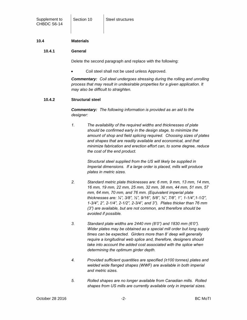
10.4 Materials
10.4.1 General
Delete the second paragraph and replace with the following:
• Coil steel shall not be used unless Approved.
Commentary: Coil steel undergoes stressing during the rolling and unrolling process that may result in undesirable properties for a given application. It may also be difficult to straighten.
10.4.2 Structural steel
Commentary: The following information is provided as an aid to the designer:
1. The availability of the required widths and thicknesses of plate should be confirmed early in the design stage, to minimize the amount of shop and field splicing required. Choosing sizes of plates and shapes that are readily available and economical, and that minimize fabrication and erection effort can, to some degree, reduce the cost of the end product.
Structural steel supplied from the US will likely be supplied in Imperial dimensions. If a large order is placed, mills will produce plates in metric sizes.
2. Standard metric plate thicknesses are: 6 mm, 9 mm, 13 mm, 14 mm, 16 mm, 19 mm, 22 mm, 25 mm, 32 mm, 38 mm, 44 mm, 51 mm, 57 mm, 64 mm, 70 mm, and 76 mm. (Equivalent imperial plate thicknesses are: ¼”, 3/8”, ½”, 9/16”, 5/8”, ¾”, 7/8”, 1”, 1-1/4”,1-1/2”, 1-3/4”, 2”, 2-1/4”, 2-1/2”, 2-3/4”, and 3”). Plates thicker than 76 mm (3”) are available, but are not common, and therefore should be avoided if possible.
3. Standard plate widths are 2440 mm (8’0”) and 1830 mm (6’0”). Wider plates may be obtained as a special mill order but long supply times can be expected. Girders more than 8’ deep will generally require a longitudinal web splice and, therefore, designers should take into account the added cost associated with the splice when determining the optimum girder depth.
4. Provided sufficient quantities are specified (≥100 tonnes) plates and welded wide flanged shapes (WWF) are available in both imperial and metric sizes.
5. Rolled shapes are no longer available from Canadian mills. Rolled shapes from US mills are currently available only in imperial sizes.

Supplement to CHBDC S6-14
Section 10 Steel structures
October 28 2016 -3- BC MoTI
Common metric angle sizes and their Imperial equivalents currently available are: L90x90x8 (L3-1/2”x3-1/2”x 5/16”), L100x100x6 (L4”x4”x1/4”), L100x100x10 (L4”x4”x3/8”), and L125x125x8 (L5”x5”x5/16”). Metric sizes included in steel handbooks are soft conversions of the imperial equivalents. .
6. Grades of steel used in bridge construction shall preferably be based on their availability. The following sections and grades of steel are usually more readily available than others and their use is recommended wherever possible:
• Angles and channels, non-weathering: 350W (equivalent to ASTM A572, Grade 50); weathering: ASTM A588, Grade 50A.
• Hollow structural sections: 350W or ASTM A500, Type B
• HP Sections: 350W (equivalent to ASTM A572, Grade 50)
• Plate: 300W, 350W, 350WT, 350A, 350AT
• Structural tees: 350W (equivalent to ASTM A572, Grade 50)
• Welded reduced wide flange shapes: 350AT, 350W
• Welded wide flange shapes: 350AT, 350W
• Wide flange shapes, non-weathering: 350W (equivalent to ASTM A572, Grade 50), weathering ASTM A588, Grade 50.
• Anchor rods: ASTM A307, Grade C (Fy = 250 MPa, 36 ksi).
• Shear studs: (refer to S6-14 clause 10.4.7)
7. Canadian mills no longer produce rolled sections. As such, rolled sections will likely be produced by American mills that will have primary designations to ASTM specifications, with possible CAN/CSA equivalency.
8. Local fabricator experience indicates that rolled sections are usually purchased as conforming to ASTM A572, Grade 50 (non-weathering) or ASTM A588 (weathering steel).
9. Local fabricator experience is that HSS is available as CSA G40.21M, Grade 350W, Class C or ASTM A500, Type B. Designers are encouraged to specify ASTM A500 because the thickness tolerances are more liberal for this grade (see CISC Bulletin dated Nov. 5, 1996). This would allow fabricators to use either grade.
10. The delivery time for welded reduced wide flange and welded wide flange shapes is sufficiently long that fabricators will often fabricate the sections rather than order them from a mill.
Supplement to CHBDC S6-14
Section 10 Steel structures
October 28 2016 -4- BC MoTI
11. Higher strength anchor rods such as ASTM A449 or ASTM F1554 (105 ksi) may be used where required.
12. It is recommended that designers not specify one particular grade of shear stud as manufacturers will not guarantee studs to meet one grade.
10.4.5 Bolts
Add the following after the second paragraph:
In general supply of bolts shall comply with the following:
1. Bolts shall preferably be 22 mm (7/8”) in diameter, although larger diameters may be used where they are deemed beneficial.
2. Bolt size and grade should be uniform throughout the design as much as possible.
3. Availability of bolts (standard, size and quantity) should be confirmed prior to start of design.
4. ASTM Standard A490 bolts, nuts, and washers shall not be used unless consented to by the Ministry.
5. Tension control bolt-nut washer assemblies (such as ASTM F1852 and ASTM F2280) and direct tension indicating (DTI) washers (such as ASTM F959) shall only be used when Approved.
Commentary:
1. Bolts may not be available in Metric sizes without ordering an entire lot, therefore, the designer should confirm the availability of bolt size and type prior to design.
2. In general, one size of bolt should be used on an entire bridge to avoid the need for multiple size wrenches and impact guns, and to avoid the possibility of undersized bolts being inadvertently installed where larger ones were specified.
3. A490 bolts are less ductile than A325 bolts and can not be galvanized. In unusual situations where A325 bolts cannot be used, A490 bolts may be considered by the Ministry.
4. See the Ministry SS 421.11.03 for coating requirements for bolts.
Supplement to CHBDC S6-14
Section 10 Steel structures
October 28 2016 -5- BC MoTI
10.4.7 Stud shear connectors
Shear stud connectors shall be comply with ASTM A108 (Grades 1015, 1018 or 1020).
10.4.10 Galvanizing and metallizing
For steel that is to be hot-dip galvanized, the following restriction is made in addition to the chemical composition (heat analysis) requirements of CAN/CSA G40.21:
• Si content; less than 0.03% or within a range of 0.15% to 0.25%
• C content; maximum of 0.25%.
• P content; maximum of 0.05%
• Mn content; maximum of 1.35%
Commentary: These elements are restricted to mitigate their adverse effects on galvanizing.
10.4.13 Pins and rollers
Add the following paragraph:
Pins and rollers shall conform to ASTM A668 and ASTM A108 as appropriate.
10.6 Durability
10.6.3 Corrosion protection
Add the following paragraphs:
Primary superstructure members shall be corrosion-resistant weathering steel unless otherwise consented to by the Ministry.
Bracing members fabricated from 300W or 350W steel shall be coated for corrosion resistance. For bracing members of these materials, the preferred method of coating shall be galvanizing or metallizing. If galvanizing or metallizing are inappropriate (e.g. for aesthetic reasons), bracing shall be coated with a paint system selected from the Ministry’s Recognized Products List.
Commentary: Due to the cost of painting, it is recommended that corrosion-resistant weathering steel be used where appropriate.

Supplement to CHBDC S6-14
Section 10 Steel structures
October 28 2016 -6- BC MoTI
10.6.4 Superstructure components
10.6.4.2 Structural steel
Delete the first paragraph and replace with the following:
For weathering steel structures, all structural steel, including contact surfaces of bolted joints, diaphragms and bracing but excluding surfaces in contact with concrete, shall be coated with a coating system selected from the Ministry’s Recognized Products List. The coating shall extend for the larger of the following two distances from locations of deck joints, such as at expansion joints and fixed joints:
• 3000 mm; or
• 1.5 x the structure depth.
In the above, the structure depth shall include the girder, haunch, and slab heights.
In areas of high exposure and for elements that are critical to the structure, the designer may consider metallizing the zone as described above. If the metallized zones will be visible from the outside of the bridge, they shall also be top-coated with paint selected from the Ministry’s Recognized Products List to match the colour of the adjacent steel elements.
For bridges constructed of weathering steel, unless the entire structure is coated, the colour of the finish coat shall match the expected colour of the final oxidized surfaces. The colour proposed shall be subject to review by the Ministry.
For structures not using weathering steel, the steel shall be coated with a coating system selected from the Ministry’s Recognized Products List and in accordance with SS 421 and SS 422.
In marine environments, or where the steel is likely to be exposed to de-icing chemicals, the steel shall be coated.
The designer shall provide details that avoid situations where water is allowed to pool on girder flanges. Where this cannot be avoided, such areas shall be painted with an immersion-grade coating system.
Bottom flange water deflector plates shall be installed as per Figure 11.6.6.6 (a).
Commentary: Experience has shown that there is little benefit from specifying corrosion-resistant steel and a complete paint system on the entire bridge. However, there may be situations where good design practice would require both.
Supplement to CHBDC S6-14
Section 10 Steel structures
October 28 2016 -7- BC MoTI
In specifying the top coat colour of the protective coating at the ends of the bridge and under deck joints, the designer shall consider how other weathering steel bridges in the area or in similar environments have weathered over time and match the coating to the expected final oxidized colour.
10.6.4.3 Cables, ropes, and strands
Delete the first paragraph and replace with the following:
A method of corrosion protection as consented to by the Ministry shall be used for all wires in the cables and hangers of suspension bridges, stay cables of cable-stayed bridges, arch bridge hangers and other cables, ropes and strands used in bridges.
Commentary: Corrosion protection systems for cables are advancing rapidly. As such, discussion with the Ministry is required when cables are used. As a minimum, wires will be hot-dip galvanized as per this clause.
10.6.5 Other components
Piling shall be sized for a corrosion allowance of at least 3 mm over the life of the structure unless a detailed corrosion analysis is undertaken. Coated piling shall not be allowed.
Commentary: It is the Ministry’s experience that coated piling has not been found to be successful. Therefore, a sacrificial thickness shall be added to the thickness required to meet structural demands. The 3 mm allowance is intended for fresh water applications. This sacrificial thickness shall be increased as required for more aggressive environments.
10.7 Design details
10.7.1 General
Design detailing shall address constraint induced fracture.
Commentary: For helpful background information and suggested details regarding the design of steel bridges, designers may refer to “Guidelines for Design Constructability,” AASHTO/NSBA Steel Bridge Collaboration, Document G12.1-2003. In the event of conflict with Canadian Standards, Canadian Standards shall prevail.
The document may be referenced at:
http://www.aisc.org/contentNSBA.aspx?id=20130
NSBA is the US-based National Steel Bridge Alliance.
Supplement to CHBDC S6-14
Section 10 Steel structures
October 28 2016 -8- BC MoTI
AASHTO LRFD Bridge Design Specifications has design specifications for constraint induced fracture.
The following Clauses shall be added to Section 10.7.1:
10.7.1.1 Flange widths between splices
Unless economic analysis indicates that other arrangements are more cost-effective, it is preferred that flange plate widths be kept constant between field splices.
Commentary: Flanges for girders are purchased in economical multi-width plates. Where a change in flange thickness occurs, the mill plates are butt welded together. If the flange width is constant for a given shipping length, the plates can be stripped into multiple flanges in one continuous operation. When determining flange widths, the designer should take into account that plate typically comes in 2440 mm (8’-0”) and/or 1830 mm (6’-0”) widths (depending on availability).
10.7.1.2 Transition of flange thicknesses at butt welds
Transition of flange thickness at butt welds shall be made in accordance with CSA Standard W59-Latest Edition, with a slope through the transition zone not greater than 1 in 2.
Commentary: A slope of 1 in 2 can be produced by burning followed by grinding in the direction of primary stress. Research indicates that this detail achieves the required fatigue categories. Less steep slopes require more expensive fabrication methods with no significant compensating improvement in fatigue classification.

Supplement to CHBDC S6-14
Section 10 Steel structures
October 28 2016 -9- BC MoTI
10.7.1.3 Recommended details
10.7.1.3.1 Coping of stiffeners and gusset plates
As shown in Figure 10.7.1.3.1 for I-girders with vertical webs, copes on details such as stiffeners and gusset plates shall be 4 to 6 times the girder web thickness but not less than 50 mm.
Figure 10.7.1.3.1 Coping of stiffeners and location of gusset plates
Commentary: Copes as dimensioned above are desirable because they:
• prevent the possibility of intersecting welds;
• reduce the high weld shrinkage strains associated with smaller copes;
• allow drainage, and;
• facilitate access for welding.
At end diaphragms, copes are not permitted.

Supplement to CHBDC S6-14
Section 10 Steel structures
October 28 2016 -10- BC MoTI
Commentary: This generally dictates the need for a drain at the diaphragm. For other situations such as the horizontal flange of a box girder with transverse stiffeners, refer to the latest edition of “Bridge Fatigue Guide Design and Details” by J.W. Fisher.
10.7.1.3.2 Gusset plates for lateral bracing
All gusset plates for lateral bracing should be fillet welded. As shown in Figure 10.7.1.3.1, they should be located a distance of 125 mm from the bottom flange for flange widths up to 400 mm or 150 mm from the bottom flange for flange widths over 400 mm; but the angle between the flange and a line connecting the flange tip and the gusset plate-to-web connection shall not be less than 30 degrees. The outer corners of the gusset plates should be left square. “Bridge Fatigue Guide, Design and Details” by J.W. Fisher should be consulted when determining the location of bolt holes.
Commentary: Two factors have been taken into consideration in determining the position of lateral bracing gusset plates.
• Access for fabricating and inspecting the gusset plate-to-web connection; and
• The improved fatigue performance which results when the gusset plate is moved away from the flange into a lower stress region.
Although this is the preferred detail, under certain circumstances (such as when fatigue stresses govern) a designer may wish to consider a radiused gusset plate or a bolted connection.
10.7.1.3.3 Frames for lateral bracing, cross-frames and diaphragms
Frames (assemblies of bracing elements and connecting plates) should be used for lateral bracing, cross-frames and diaphragms in lieu of angle sections shipped loose to the site. The frames for use between girders should be detailed for shipping and erection as a single unit. A sample arrangement is shown in Figure 10.7.1.3.3.
Frames should be designed for fabrication from one side, eliminating the need for “turning over” during fabrication. Oversized holes in the gusset plates are permitted.
Bracing shall be designed to accommodate both construction loading and the final loading on the structure. The designer shall identify any assumptions regarding construction loading on the drawings.
The designer shall account for eccentric force effects for both strength and fatigue arising from the arrangement described above.

Supplement to CHBDC S6-14
Section 10 Steel structures
October 28 2016 -11- BC MoTI
The arrangement described above may result in heavy members, stiffeners and connections because of additional stresses from eccentric load paths that must be carefully accounted for in the design.
Figure 10.7.1.3.3 Typical diaphragm
Commentary: Frame brace systems for use between girders should consist of angles or tees shop welded to one side of gusset plates which would be field bolted to the girder stiffeners. Efficient fabrication and erection procedures result when frames can be produced in one jig and when fewer pieces are handled in the field.

Supplement to CHBDC S6-14
Section 10 Steel structures
October 28 2016 -12- BC MoTI
10.7.1.3.4 Box girder diaphragm bracing
Unless design requirements dictate otherwise, 100 x 100 x 10 mm angles should be considered as a standard angle size for box girder bracing. If additional interior bracing is required for handling of the girders (in excess of what the contract drawings call for), the fabricator shall propose such on the shop drawings which shall then be subject to approval by the designer. Care shall be exercised to address issues of constructability, account for eccentric load paths, satisfy the Ultimate Limit State and preclude those details that would compromise the Fatigue Limit State requirements. Figure 10.7.1.3.4 suggests two concepts for consideration.
Figure 10.7.1.3.4 Box girder bracing at diaphragm
Commentary: Because of minimum tonnage orders that can be placed with mills, standardization of angle bracing will result in economy. The 100 x 100 x 10 angle is believed to be adequate for the normal range of bridge spans.
10.7.1.3.5 Intermediate diaphragms in shallow girders
Constant depth intermediate diaphragms, in lieu of frame bracing, are preferred in I-girders bridges up to approximately 1200 mm in girder depth.
Commentary: Diaphragms comprising channel or beam sections would be less expensive in shallow bridges.
10.7.1.3.6 Box girder diaphragms at piers and abutments
Diaphragms at piers should be detailed so that the box girder and diaphragm flanges are not connected (see Figure 10.7.1.3.6 (a)) showing two possible solutions. Also, provisions for jacking within the width of the bottom flange

Supplement to CHBDC S6-14
Section 10 Steel structures
October 28 2016 -13- BC MoTI
should be provided for by the designer. Diaphragms at abutments are normally of a shallower depth to allow for deck details. In this case, the box girder flanges should be stabilized against rotation (see Figure 10.7.1.3.6 (b)). Diaphragms between box girders at piers and abutments should be of constant depth, and bolted to exterior box girder web stiffeners (see Figure 10.7.1.3.6 (c)). Oversized holes in diaphragms or stiffeners are permitted.
Figure 10.7.1.3.6 Box girder diaphragms
Commentary: The details as shown in Figure 10.7.1.3.6, are suggested to meet design and fabrication needs.
10.7.1.3.7 Transitions of box girder flange and web thicknesses
Flange thickness transitions should be made so that a constant depth web plate is maintained. Web thickness transitions should be made to maintain a flush inner box girder face.
Commentary: Flange thickness transitions, made so that a constant web depth is maintained, result in economy. Web thickness transitions made so that a flush inner face is maintained makes for repetition of inner diaphragms which then act as “templates” for maintaining the geometric shape of the box. Different fabricators with different equipment and assembly procedures will

Supplement to CHBDC S6-14
Section 10 Steel structures
October 28 2016 -14- BC MoTI
have distinct opinions and different preferences and there are really no rigid rules that would satisfy all conditions. Note that eccentric transitions produce small local bending effects which can be significant where elastic instability is possible, e.g. in tension plates temporarily subject to compression during construction.
If erection by launching is an option contemplated in the design, the underside of the bottom flange should be kept a constant width to facilitate lateral guiding and the plate thickness transitions should be made into the web to have a flush bottom flange surface in contact with the supports.
10.7.1.3.8 Grinding of butt welds
Grinding of butt welds shall be finished parallel to the direction of primary tensile stress and in accordance with CSA W59.
Butt welds in webs of girders designed for tension in Category B shall be “flush” for a distance of at least 1/3 the web depth from the tension flange.
All other butt welds designed for tension in Category B shall be “flush.”
Butt welds designed for compression only or for stresses in Category C shall be at least “smooth”.
“Flush” is defined as a smooth gradual transition between base and weld metal, involving grinding where necessary to remove all surface lines and to permit RT and UT examination. Weld reinforcement not exceeding 1 mm in height may remain on each surface, unless the weld is part of a faying surface, in which case all reinforcement shall be removed.
“Smooth” is defined for the surface finish of weld reinforcement to provide a sufficiently smooth gradual transition, involving grinding where necessary to remove all surface lines and to permit RT or UT examination. Weld reinforcement not exceeding the following limits may remain on each surface:
• for plate thicknesses < 50 mm, 2 mm
• for plate thicknesses > 50 mm, 3 mm
Commentary: In webs of girders, butt welds more than approximately 1/3 the girder depth from the tension flange are in a lower stress range. This results in a less severe fatigue category not requiring the “flush” condition. The designer is responsible for confirming whether more or less stringent limits are warranted.
Where the contour of the weld is to be “smooth” grinding may be required to permit RT or UT examination of the tension welds. Compression welds may require grinding if the weld reinforcement limits specified above are not met.

Supplement to CHBDC S6-14
Section 10 Steel structures
October 28 2016 -15- BC MoTI
10.7.1.3.9 Vertical stiffeners
Bearing stiffeners on plate girder bridges shall be true vertical under full dead load with the requirement noted on the contract documents. Intermediate stiffeners may be either true vertical, or perpendicular to fabrication work lines, depending on the fabricator’s practice.
Commentary: The recommendation for bearing stiffeners to be true vertical under full dead load is primarily for aesthetics with the normal pier and abutment designs. Vertical diaphragms would also result at the bearing points which will facilitate the jacking arrangement for bearing maintenance. Some fabricators choose to work from a horizontal work line on the webs of girders and install intermediate stiffeners perpendicular to these work lines with the girder in a relaxed condition. When the dead load acts, the intermediate stiffeners are not vertical, but the difference is slight with no functional loss.
If all stiffeners (bearing, intermediate and diaphragms) are vertical then modular repetition of the lateral bracing system can be attained which may be desirable for detailing and fabrication.
10.7.1.3.10 Bearing stiffener to flange connection
As shown in Figure 10.7.1.3.10, bearing stiffeners up to 20 mm thick may be welded to both flanges at abutments, and fitted to the tension flange and welded to the compression flange at interior supports. The size of weld shall be specified on the contract drawings. Bearing stiffeners over 20 mm thick shall be fitted and welded to both flanges at abutments and shall be fitted to both flanges and welded to the compression flange at interior supports.
Care shall be exercised in the design and during fabrication to mitigate distortions of the bottom flange from welding of the bearing stiffeners so as to ensure a flat surface for the bearing.
Bearing stiffeners at diaphragm locations shall either be welded or bolted.

Supplement to CHBDC S6-14
Section 10 Steel structures
October 28 2016 -16- BC MoTI
Figure 10.7.1.3.10
Bearing stiffener to flange connections
Commentary: The load in bearing stiffeners over 20 mm thick would normally be too great to be carried by the stiffener to flange welds; thus fitting to bear is recommended. Welds may be used for load transfer in thinner bearing stiffeners but fitting to bear is not excluded.
10.7.1.3.11 Intermediate stiffener to flange connection
In plate girders up to a depth of 2000 mm, in the positive moment regions, the intermediate stiffeners shall be cut short of the tension flange except that stiffeners at lateral bracing, cross-frame, and diaphragm connections may be either fitted, bolted or welded to the tension flange, depending on the strength and fatigue requirements. In negative moment regions, all intermediate stiffeners should be fitted to bear on the tension flange and welded to the compression flange.
In plate girders over a depth of 2000 mm, all intermediate stiffeners should be welded to the compression flange. The stiffeners can be welded, bolted or

Supplement to CHBDC S6-14
Section 10 Steel structures
October 28 2016 -17- BC MoTI
fitted to the tension flange, depending on the strength and fatigue requirements and economic considerations.
Commentary: In plate girders over a depth of 2000 mm, racking of the flanges during shipment may result in cracks forming in the web/flange weld if intermediate stiffeners are cut short of the flange. To avoid this problem, the intermediate stiffeners should be fitted, bolted or welded to the tension flange. If the stiffeners are on one side of the web only, fabrication and transportation requirements may dictate some additional means of preventing flange rotation.
10.7.1.3.12 Stiffener to web connection
All stiffeners shall be welded to the webs of the girders by continuous fillet welds, of the minimum required size.
Commentary: Continuous welding improves the fatigue performance in a girder by reducing the number of stress raisers. The minimum weld size is specified to reduce residual stresses and web deformations.
10.7.1.3.13 Intersecting longitudinal and transverse stiffeners
Longitudinal stiffeners shall be located on the opposite side of the girder web to intermediate transverse stiffeners, unless detailing precludes this. Where longitudinal and transverse stiffeners intersect, the longitudinal stiffener should be cut short of the transverse stiffener. However, in tension regions, where fatigue is a governing design criterion, and where longitudinal and transverse stiffeners intersect, the longitudinal stiffener may be made continuous and the transverse stiffener welded to it at the intersection.
Commentary: Longitudinal stiffeners should be continuous as much as practical, especially in the case of fracture-critical members. The designer may wish to modify the design to avoid the need for longitudinal stiffeners which may result in more material but potentially cheaper fabrication.
Locating longitudinal and transverse stiffeners on opposite sides of girder webs facilitates fabrication and reduces the number of stress-raisers in the web of the girder.
Where intersection of stiffeners is unavoidable, cutting the longitudinal stiffener in tension regions results in a Category E detail which may be improved by providing a radiused transition if this Category is too severe, or by making the longitudinal stiffener continuous and welding the transverse stiffener to it, resulting in a Category C detail.
Supplement to CHBDC S6-14
Section 10 Steel structures
October 28 2016 -18- BC MoTI
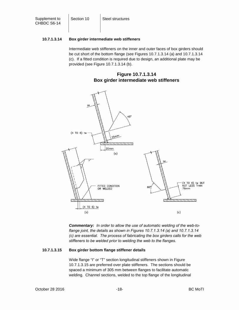
10.7.1.3.14 Box girder intermediate web stiffeners
Intermediate web stiffeners on the inner and outer faces of box girders should be cut short of the bottom flange (see Figures 10.7.1.3.14 (a) and 10.7.1.3.14 (c). If a fitted condition is required due to design, an additional plate may be provided (see Figure 10.7.1.3.14 (b).
Figure 10.7.1.3.14 Box girder intermediate web stiffeners
Commentary: In order to allow the use of automatic welding of the web-to-flange joint, the details as shown in Figures 10.7.1.3.14 (a) and 10.7.1.3.14 (c) are essential. The process of fabricating the box girders calls for the web stiffeners to be welded prior to welding the web to the flanges.
10.7.1.3.15 Box girder bottom flange stiffener details
Wide flange “I” or “T” section longitudinal stiffeners shown in Figure 10.7.1.3.15 are preferred over plate stiffeners. The sections should be spaced a minimum of 305 mm between flanges to facilitate automatic welding. Channel sections, welded to the top flange of the longitudinal

Supplement to CHBDC S6-14
Section 10 Steel structures
October 28 2016 -19- BC MoTI
stiffeners and to the inner web stiffeners, are the preferred arrangement for transverse stiffening.
Figure 10.7.1.3.15 Box girder bottom flange stiffener details
10.7.4 Camber
10.7.4.1 Design
Delete the second paragraph and replace with the following:
Camber information shall be provided by the designer. Camber shall be shown at splice points and at intervals not greater than 2 m.
A camber diagram shall be included in the Plans and shall include elevations for:
(a) the target finished steel girder grades.
(b) camber profiles for deflections due to the deck, curbs, sidewalks, barriers, railings, wearing surface, creep and shrinkage, and utilities.
(c) camber profiles for deflections due to steelwork (girders, beams, bracing, diaphragms etc.)

Supplement to CHBDC S6-14
Section 10 Steel structures
October 28 2016 -20- BC MoTI
Commentary: Item (c) is required by the steel fabricator. Item (b) is required by the erector to set the girders. Differences between the surveyed profile of the erected steelwork and Item (b) are used to adjust the height of slab haunches over the girders to attain the target finished grade profile.
10.18 Splices and connections
10.18.1 General
Add the following paragraphs:
Field splices shall be bolted connections.
Locations of slip-critical connections shall be shown on the Plans
Connections for cables (hangers, suspension cables, cable stays, etc.) shall be designed and/or specified so that the ultimate breaking strength of the connection exceeds the maximum guaranteed tensile strength of the cable.
Commentary: This requirement is included to ensure that failure occurs via yielding of the cable element and not failure of the connection.
Compression flange splices shall use a bolted connection designed using the forces given in Section 10.18.1.1.
Commentary: Splices for compression flanges that rely on bearing between the ends of the flange plates are not permitted. This splice detail has been used on bridges with precast deck panels to avoid splice plates above the top flange and therefore simplify deck panel fabrication and installation. However, during the evaluation of extreme overloads, sections with this splice detail have been found to limit capacity.
10.18.3 Welds
10.18.3.1 General
The matching electrode classifications for ASTM A709 steels shall be as specified in Table 10.10B.

Supplement to CHBDC S6-14
Section 10 Steel structures
October 28 2016 -21- BC MoTI
The designer shall specify any testing requirements for welds that are required in addition to the testing requirements of SS 421.
Commentary: SS 421 generally outlines the expected extent of weld testing for Ministry projects which the designer should be familiar with. The designer is reminded that W59 requires the engineer to specify the type and extent of testing for welds.
10.19 Anchor rods
10.19.1 General
Delete the second paragraph and replace with the following:
Anchors shall comply with the following:
• Anchor rods for bearing assemblies shall have a minimum diameter of 25 mm and a minimum embedment length of 300 mm.
• Anchor rods, including nuts and washers, shall be galvanized or metallized;
• Anchor rod nuts shall be secured by spoiling the threads after installation;
• Proprietary anchorage systems may be used only with the consent of the Ministry;
• Mechanical anchorage systems shall not be used.
Commentary:
Based on inspection of existing bridges, it is prudent to galvanize anchor rods and their components that are not embedded in the concrete and are exposed to damage from corrosion.
10.23 Fracture control
10.23.3 Fracture toughness
10.23.3.3 Fracture-critical members
Delete Table 10.13 title and replace with “Impact test temperatures and Charpy impact energy requirements for fracture-critical members”
Commentary: The second sentence refers to Table 10.13 for impact energy requirements for fracture-critical members however, Table 13 title refers to primary tension members.

Supplement to CHBDC S6-14
Section 10 Steel structures
October 28 2016 -22- BC MoTI
A10.1 Construction requirements for structural steel
A10.1.1 General
Construction shall be in accordance with SS 421 unless amended by the Supplement or otherwise Approved. SS 421 shall take precedence over CHBDC S6-14 where there is a conflict between these documents.
The Plans shall clearly define all construction requirements.
A10.1.5 Welded construction
A10.1.5.1 General
Field welding of attachments to girders shall only be permitted where consented to by the Ministry.
Commentary: Quality Assurance of field welding can be problematic. Field welding is strongly discouraged but permission may be granted in unique circumstances.
A10.1.6 Bolted construction
A10.1.6.4 Installation of bolts
Add the following paragraph:
Fully tensioned bolts shall be installed in all bolt holes used for erection.
A10.1.8.2 Non-destructive testing of welds
Ultrasonic Testing (UT) may supplement Radiographic Testing (RT) subject to Approval by the Ministry and acceptance by the designer.
Commentary: In thicker plate, UT testing may reveal defects not readably apparent from the RT testing.