Bridge Overhang Brackets - Construction...
57
57 09-11 ® Bridge Overhang Brackets Bridge Overhang Brackets C-49, C-49-D, C-49-S and C-49-JR Bridge Overhang Brackets Dayton Superior offers the bridge contractor four different versions of the C-49 Bridge Overhang Bracket, which allows for maximum adjustability to meet the varied bridge overhang forming requirements on both struc- tural steel and precast/prestressed concrete beams. The C-49 is the most versatile overhang bracket available and is used for general conditions. The C-49-D version is used on deep beams. The C-49-D bracket is identical to the C-49 bracket, except it uses longer bottom diagonal and vertical legs. The C-49-S bracket is a field modified C-49. The C-49 is modified by removing the inner vertical leg. Using only the outer vertical leg, the bracket can be adjusted to a minimum vertical height of 14”. This bracket is ideal for use on short steel or concrete beams. The C-49-JR is a small bracket used in situations where the horizontal member of the standard C-49 Over- hang Bracket is too long, due to limited space between twin bridges. The adjusting nut at the outboard end of the bracket is used to adjust the bracket to grade. Each of these brackets offer the bridge contractor, the ability to easily and quickly preset the brackets to size and shape on the ground, as required for each specific overhang requirement. The adjusting nut and the wide range of adjustability built into the brackets vertical and diagonal legs allow a bracket to be adjusted to fit almost any standard bridge overhang. Both the vertical and diagonal legs have adjustment holes spaced at 2” increments which allows the legs to be adjusted so the diagonal leg will transfer the construction load to near the bottom flange, which aids in resisting web deflection and bending . The C-54 Extender, C-52, C-52P and C-53 Guardrail Receptacles, and C-51 Wall Plate Assemblies add to the versatility of the C-49 overhang brackets. Bracket Type Vertical Adjustment Range Horizontal Length C-49 30" - 50" 54" C-49-D 50" - 70" 54" C-49-S 16" - 28" 54" C-49-JR 16" - 28" 27" SAFETY NOTE: Overhang brackets should be adjusted to proper grade during the normal “dry run” operation. DO NOT attempt an upward adjustment during the concrete pouring operation. Lowering the bracket is permissible during the concrete pour Vertical Adjustment Range Horizontal Length
Transcript of Bridge Overhang Brackets - Construction...
5709-11
®
Bridge Overhang Brackets
Bri
dg
e O
verh
ang
B
rack
ets
C-49, C-49-D, C-49-S and C-49-JR Bridge Overhang Brackets Dayton Superior offers the bridge contractor four different versions of the C-49 Bridge Overhang Bracket,
which allows for maximum adjustability to meet the varied bridge overhang forming requirements on both struc-tural steel and precast/prestressed concrete beams. The C-49 is the most versatile overhang bracket available and is used for general conditions.
The C-49-D version is used on deep beams. The C-49-D bracket is identical to the C-49 bracket, except it uses longer bottom diagonal and vertical legs.
The C-49-S bracket is a field modified C-49. The C-49 is modified by removing the inner vertical leg. Using only the outer vertical leg, the bracket can be adjusted to a minimum vertical height of 14”. This bracket is ideal for use on short steel or concrete beams.
The C-49-JR is a small bracket used in situations where the horizontal member of the standard C-49 Over-hang Bracket is too long, due to limited space between twin bridges.
The adjusting nut at the outboard end of the bracket is used to adjust the bracket to grade.
Each of these brackets offer the bridge contractor, the ability to easily and quickly preset the brackets to size and shape on the ground, as required for each specific overhang requirement. The adjusting nut and the wide range of adjustability built into the brackets vertical and diagonal legs allow a bracket to be adjusted to fit almost any standard bridge overhang.
Both the vertical and diagonal legs have adjustment holes spaced at 2” increments which allows the legs to be adjusted so the diagonal leg will transfer the construction load to near the bottom flange, which aids in resisting web deflection and bending .
The C-54 Extender, C-52, C-52P and C-53 Guardrail Receptacles, and C-51 Wall Plate Assemblies add to the versatility of the C-49 overhang brackets.
Bracket Type
Vertical Adjustment
Range
Horizontal Length
C-49 30" - 50" 54"C-49-D 50" - 70" 54"C-49-S 16" - 28" 54"C-49-JR 16" - 28" 27"
SAFETY NOTE: Overhang brackets should be adjusted to proper grade during the normal “dry run”
operation.
DO NOT attempt an upwardadjustment during the concrete pouring
operation. Lowering the bracket is permissible during the concrete pour
Vertical Adjustment
Range
Horizontal Length
58 09-11
®
Bridge Overhang Brackets
Brid
ge O
verhan
g
Brackets
Type C-49, C-49-D, C-49-S and C-49-JR Bridge Overhang Brackets
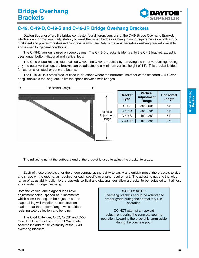
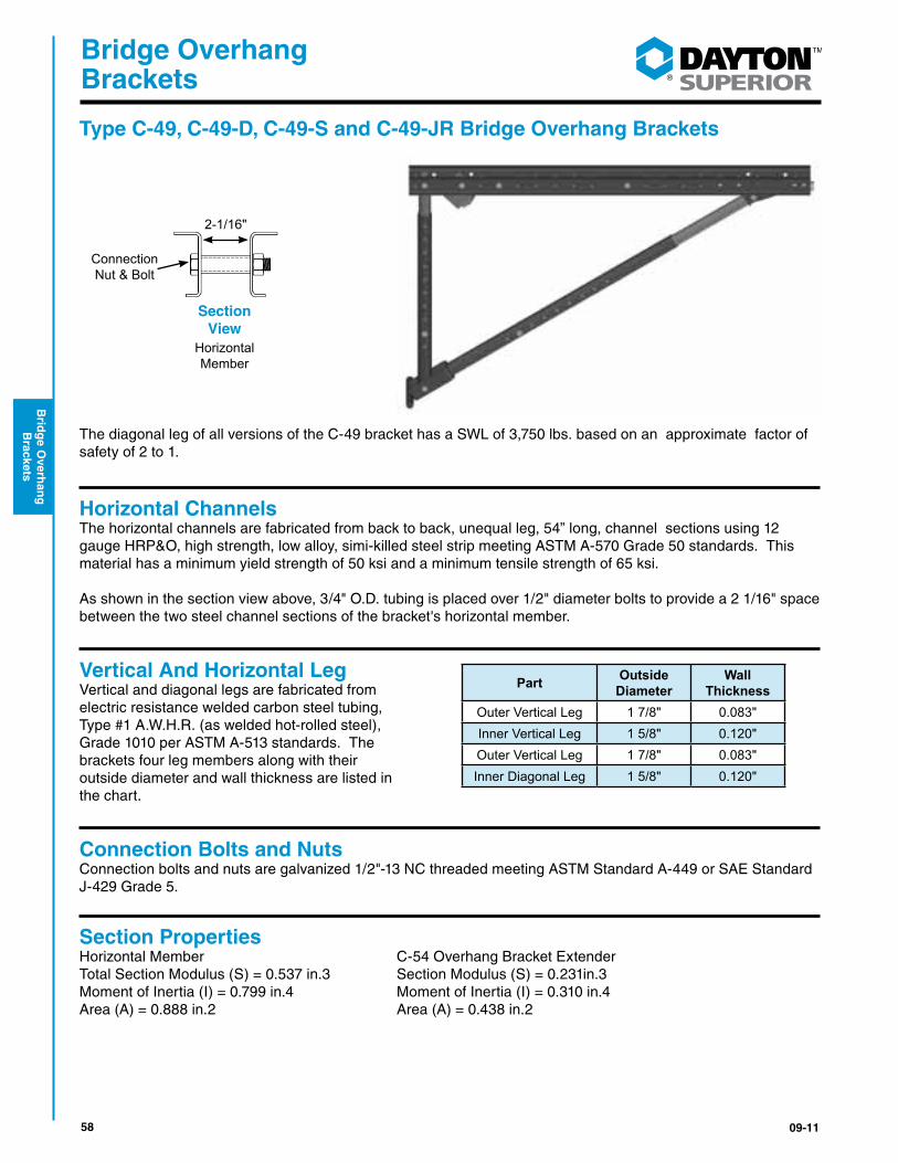
The diagonal leg of all versions of the C-49 bracket has a SWL of 3,750 lbs. based on an approximate factor of safety of 2 to 1.
Horizontal ChannelsThe horizontal channels are fabricated from back to back, unequal leg, 54” long, channel sections using 12 gauge HRP&O, high strength, low alloy, simi-killed steel strip meeting ASTM A-570 Grade 50 standards. This material has a minimum yield strength of 50 ksi and a minimum tensile strength of 65 ksi.
As shown in the section view above, 3/4" O.D. tubing is placed over 1/2" diameter bolts to provide a 2 1/16" space between the two steel channel sections of the bracket's horizontal member.
Vertical And Horizontal LegVertical and diagonal legs are fabricated from electric resistance welded carbon steel tubing, Type #1 A.W.H.R. (as welded hot-rolled steel), Grade 1010 per ASTM A-513 standards. The brackets four leg members along with their outside diameter and wall thickness are listed in the chart.
Connection Bolts and NutsConnection bolts and nuts are galvanized 1/2"-13 NC threaded meeting ASTM Standard A-449 or SAE Standard J-429 Grade 5.
Section PropertiesHorizontal Member C-54 Overhang Bracket ExtenderTotal Section Modulus (S) = 0.537 in.3 Section Modulus (S) = 0.231in.3Moment of Inertia (I) = 0.799 in.4 Moment of Inertia (I) = 0.310 in.4Area (A) = 0.888 in.2 Area (A) = 0.438 in.2
2-1/16"
Connection Nut & Bolt
Horizontal Member
Section View
Part Outside Diameter
Wall Thickness
Outer Vertical Leg 1 7/8" 0.083"Inner Vertical Leg 1 5/8" 0.120"Outer Vertical Leg 1 7/8" 0.083"Inner Diagonal Leg 1 5/8" 0.120"
5909-11
®
Bridge Overhang Brackets
Bri
dg
e O
verh
ang
B
rack
ets
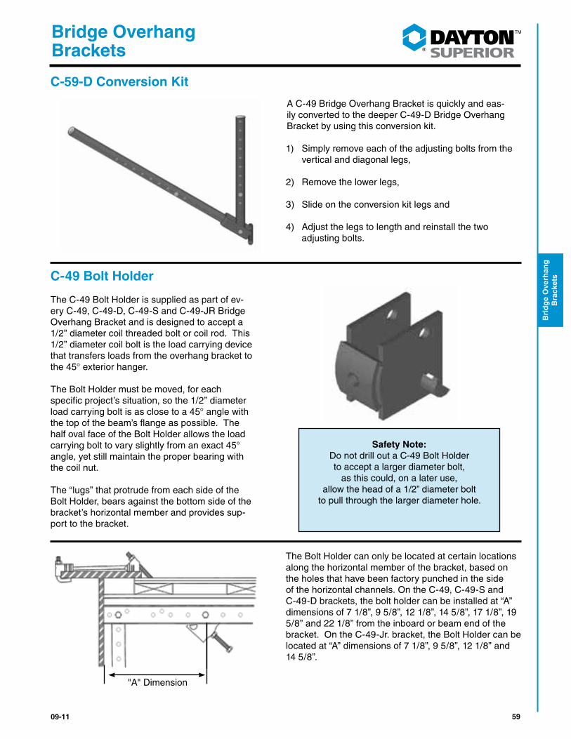
C-59-D Conversion Kit
A C-49 Bridge Overhang Bracket is quickly and eas-ily converted to the deeper C-49-D Bridge Overhang Bracket by using this conversion kit.
1) Simply remove each of the adjusting bolts from the vertical and diagonal legs,
2) Remove the lower legs,
3) Slide on the conversion kit legs and
4) Adjust the legs to length and reinstall the two adjusting bolts.
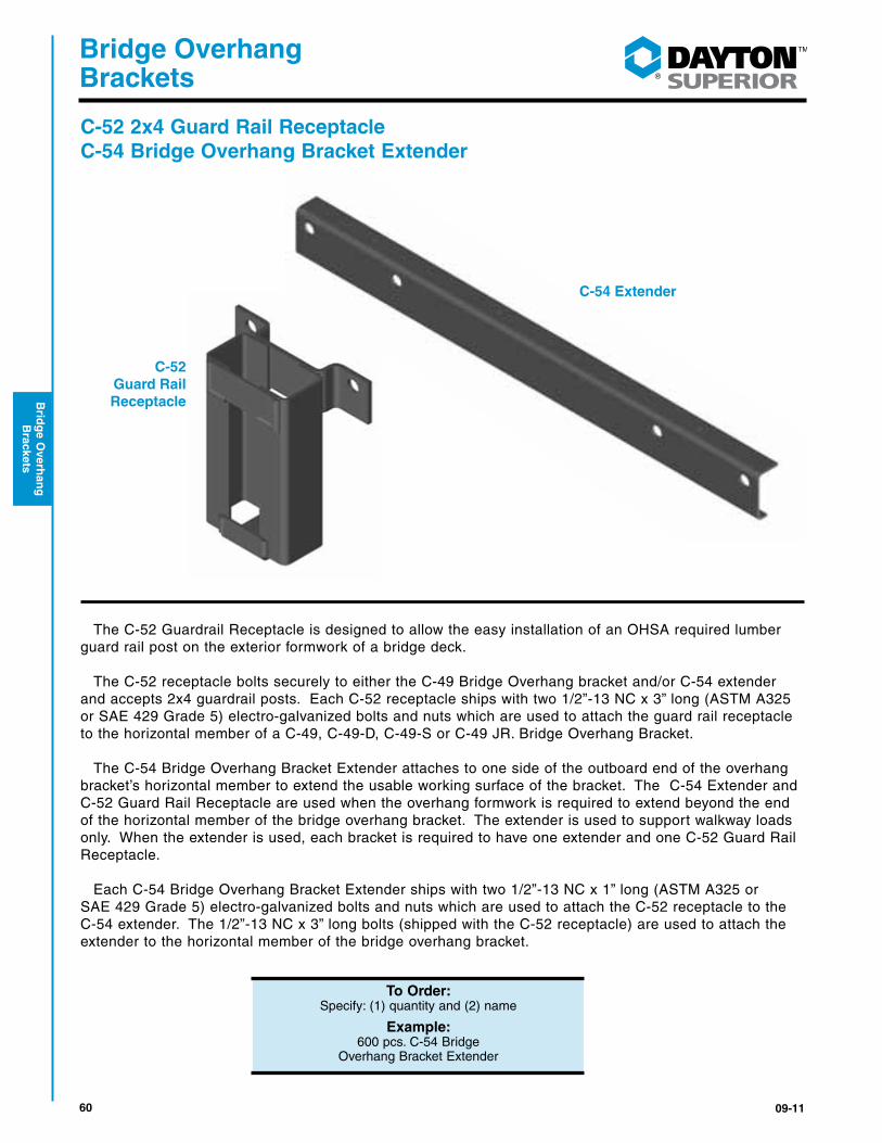
C-49 Bolt Holder The C-49 Bolt Holder is supplied as part of ev-ery C-49, C-49-D, C-49-S and C-49-JR Bridge Overhang Bracket and is designed to accept a 1/2” diameter coil threaded bolt or coil rod. This 1/2” diameter coil bolt is the load carrying device that transfers loads from the overhang bracket to the 45° exterior hanger.
The Bolt Holder must be moved, for each specific project’s situation, so the 1/2” diameter load carrying bolt is as close to a 45° angle with the top of the beam’s flange as possible. The half oval face of the Bolt Holder allows the load carrying bolt to vary slightly from an exact 45° angle, yet still maintain the proper bearing with the coil nut.
The “lugs” that protrude from each side of the Bolt Holder, bears against the bottom side of the bracket’s horizontal member and provides sup-port to the bracket.
The Bolt Holder can only be located at certain locations along the horizontal member of the bracket, based on the holes that have been factory punched in the side of the horizontal channels. On the C-49, C-49-S and C-49-D brackets, the bolt holder can be installed at “A” dimensions of 7 1/8”, 9 5/8”, 12 1/8”, 14 5/8”, 17 1/8”, 19 5/8” and 22 1/8” from the inboard or beam end of the bracket. On the C-49-Jr. bracket, the Bolt Holder can be located at “A” dimensions of 7 1/8”, 9 5/8”, 12 1/8” and 14 5/8”.
Safety Note:
Do not drill out a C-49 Bolt Holder to accept a larger diameter bolt,
as this could, on a later use, allow the head of a 1/2” diameter bolt
to pull through the larger diameter hole.
"A" Dimension
60 09-11
®
Bridge Overhang Brackets
Brid
ge O
verhan
g
Brackets
C-52 2x4 Guard Rail Receptacle C-54 Bridge Overhang Bracket Extender
The C-52 Guardrail Receptacle is designed to allow the easy installation of an OHSA required lumber guard rail post on the exterior formwork of a bridge deck.
The C-52 receptacle bolts securely to either the C-49 Bridge Overhang bracket and/or C-54 extender and accepts 2x4 guardrail posts. Each C-52 receptacle ships with two 1/2”-13 NC x 3” long (ASTM A325 or SAE 429 Grade 5) electro-galvanized bolts and nuts which are used to attach the guard rail receptacle to the horizontal member of a C-49, C-49-D, C-49-S or C-49 JR. Bridge Overhang Bracket.
The C-54 Bridge Overhang Bracket Extender attaches to one side of the outboard end of the overhang bracket’s horizontal member to extend the usable working surface of the bracket. The C-54 Extender and C-52 Guard Rail Receptacle are used when the overhang formwork is required to extend beyond the end of the horizontal member of the bridge overhang bracket. The extender is used to support walkway loads only. When the extender is used, each bracket is required to have one extender and one C-52 Guard Rail Receptacle.
Each C-54 Bridge Overhang Bracket Extender ships with two 1/2”-13 NC x 1” long (ASTM A325 or SAE 429 Grade 5) electro-galvanized bolts and nuts which are used to attach the C-52 receptacle to the C-54 extender. The 1/2”-13 NC x 3” long bolts (shipped with the C-52 receptacle) are used to attach the extender to the horizontal member of the bridge overhang bracket.
C-54 Extender
C-52 Guard Rail Receptacle
To Order:Specify: (1) quantity and (2) name
Example:600 pcs. C-54 Bridge
Overhang Bracket Extender
6109-11
®
Bridge Overhang Brackets
Bri
dg
e O
verh
ang
B
rack
ets
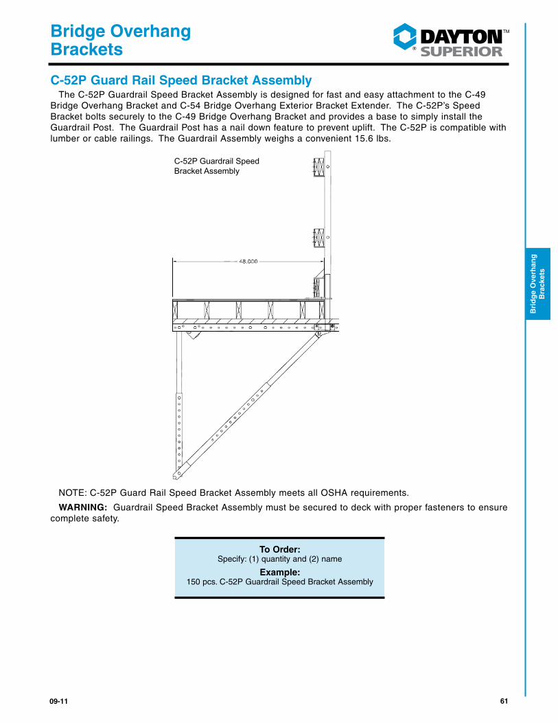
C-52P Guard Rail Speed Bracket AssemblyThe C-52P Guardrail Speed Bracket Assembly is designed for fast and easy attachment to the C-49
Bridge Overhang Bracket and C-54 Bridge Overhang Exterior Bracket Extender. The C-52P’s Speed Bracket bolts securely to the C-49 Bridge Overhang Bracket and provides a base to simply install the Guardrail Post. The Guardrail Post has a nail down feature to prevent uplift. The C-52P is compatible with lumber or cable railings. The Guardrail Assembly weighs a convenient 15.6 lbs.
NOTE: C-52P Guard Rail Speed Bracket Assembly meets all OSHA requirements.
WARNING: Guardrail Speed Bracket Assembly must be secured to deck with proper fasteners to ensure complete safety.
To Order:Specify: (1) quantity and (2) name
Example:150 pcs. C-52P Guardrail Speed Bracket Assembly
C-52P Guardrail Speed Bracket Assembly
62 09-11
®
Bridge Overhang Brackets
Brid
ge O
verhan
g
Brackets
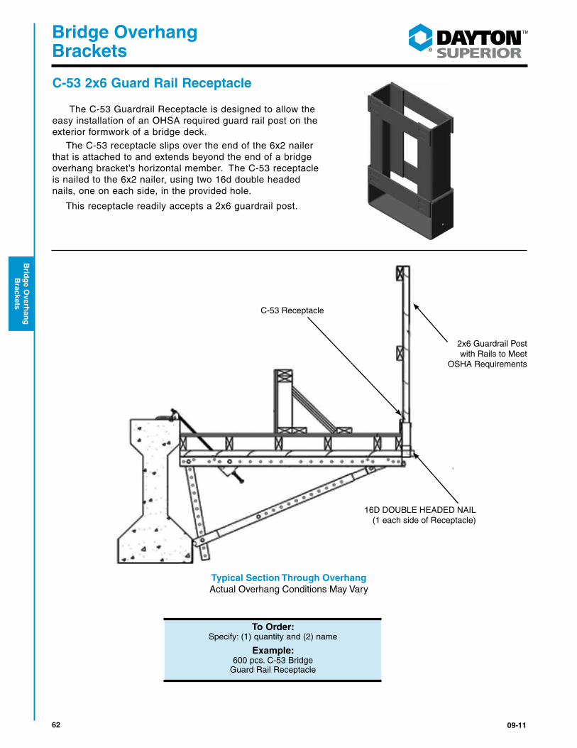
C-53 2x6 Guard Rail Receptacle
The C-53 Guardrail Receptacle is designed to allow the easy installation of an OHSA required guard rail post on the exterior formwork of a bridge deck.
The C-53 receptacle slips over the end of the 6x2 nailer that is attached to and extends beyond the end of a bridge overhang bracket’s horizontal member. The C-53 receptacle is nailed to the 6x2 nailer, using two 16d double headed nails, one on each side, in the provided hole.
This receptacle readily accepts a 2x6 guardrail post.
To Order:Specify: (1) quantity and (2) name
Example:600 pcs. C-53 Bridge
Guard Rail Receptacle
Typical Section Through OverhangActual Overhang Conditions May Vary
C-53 Receptacle
16D DOUBLE HEADED NAIL(1 each side of Receptacle)
2x6 Guardrail Post with Rails to Meet
OSHA Requirements
6309-11
®
Bridge Overhang Brackets
Bri
dg
e O
verh
ang
B
rack
ets
Selected OSHA Safety Regulations For complete information see www.osha.gov
1926.501(b)(2)(ii) Each employee on a walking/working surface 6 feet or more above a lower level where leading edges are under construction, but who is not engaged in the leading edge work, shall be protected from falling by a guardrail system, safety net system, or personal fall arrest system. If a guardrail system is chosen to provide the fall protection, and a controlled access zone has already been established for leading edge work, the control line may be used in lieu of a guardrail along the edge that parallels the leading edge. The standard requires guardrail systems and components to be designed and built to meet the requirements of 1926.502(b)(3), (4), and (5).
This Appendix serves as a non-mandatory guideline to assist employers in complying with these re-quirements. An employer may use these guidelines.
1926.501(b)(2)(i) .... However, the guidelines do not provide all the information necessary to build a complete system, and the employer is still responsible for designing and assembling these components in such a way that the completed system will meet the requirements of 1926.502(b)(3), (4), and (5). Components for which no specific guidelines are given in this Appendix (e.g., joints, base connections, components made with other materials, and components with other dimensions) must also be de-signed and constructed in such a way that the completed system meets the requirements of 1926.502.
(1) For wood railings: Wood components shall be minimum 1,500 lb-ft/in (2) fiber (stress grade) con-struction grade lumber; the posts shall be at least 2” x 4” lumber spaced not more than 8 feet apart on centers; the top rail shall be at least 2” x 4” lumber, the intermediate rail shall be at least 1” x 6”. All lumber dimensions are nominal sizes as provided by the American Softwood Lumber Standards.
1926.502(b) "Guardrail systems." Guardrail systems and their use shall comply with the following pro-visions:
1926.502(b)(1) Top edge height of top rails, or equivalent guardrail system members, shall be 42” plus or minus 3” above the walking/working level. When conditions warrant, the height of the top edge may exceed the 45” height, provided the guardrail system meets all other criteria of this paragraph .1926.502(b)(3) Guardrail systems shall be capable of withstanding, without failure, a force of at least 200 pounds applied within 2” of the top edge, in any outward or downward direction, at any point along the top edge. Guardrail systems shall be so surfaced as to prevent injury to an employee from punc-tures or lacerations, and to prevent snagging of clothing.
1926.502(b)(7) The ends of all top rails and midrails shall not overhang the terminal posts, except where such overhang does not constitute a projection hazard.
64 09-11
®
Bridge Overhang Brackets
Brid
ge O
verhan
g
Brackets
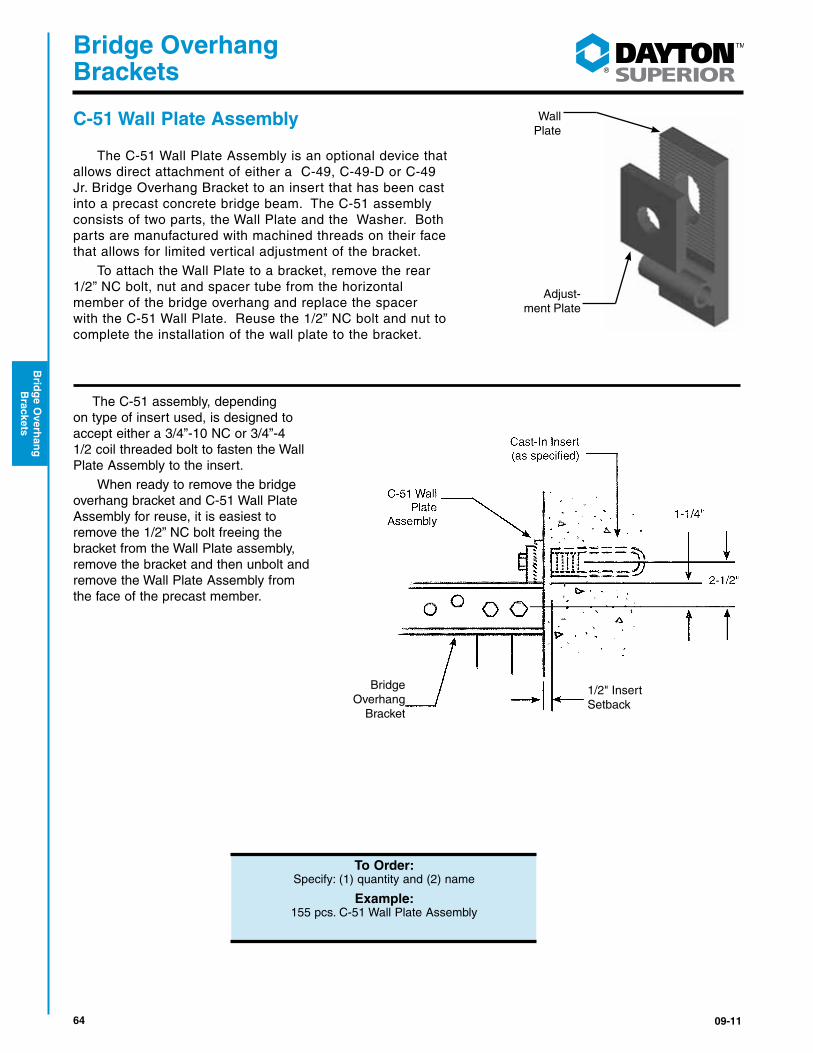
C-51 Wall Plate Assembly
The C-51 Wall Plate Assembly is an optional device that allows direct attachment of either a C-49, C-49-D or C-49 Jr. Bridge Overhang Bracket to an insert that has been cast into a precast concrete bridge beam. The C-51 assembly consists of two parts, the Wall Plate and the Washer. Both parts are manufactured with machined threads on their face that allows for limited vertical adjustment of the bracket.
To attach the Wall Plate to a bracket, remove the rear 1/2” NC bolt, nut and spacer tube from the horizontal member of the bridge overhang and replace the spacer with the C-51 Wall Plate. Reuse the 1/2” NC bolt and nut to complete the installation of the wall plate to the bracket.
The C-51 assembly, depending on type of insert used, is designed to accept either a 3/4”-10 NC or 3/4”-4 1/2 coil threaded bolt to fasten the Wall Plate Assembly to the insert.
When ready to remove the bridge overhang bracket and C-51 Wall Plate Assembly for reuse, it is easiest to remove the 1/2” NC bolt freeing the bracket from the Wall Plate assembly, remove the bracket and then unbolt and remove the Wall Plate Assembly from the face of the precast member.
To Order:Specify: (1) quantity and (2) name
Example:155 pcs. C-51 Wall Plate Assembly
Cast-In Insert (as specified)
2-1/2"
1-1/4"
Wall Plate
Adjust-ment Plate
Bridge Overhang
Bracket
1/2" Insert Setback

6509-11
®
Bridge Overhang Brackets
Bri
dg
e O
verh
ang
B
rack
ets
B-16 Coil Loop Insert, 3/4" x 6"Although simple in design and fabrication, the 3/4” diameter x 6”
long B-16 Coil Loop Insert is highly efficient for use in attaching the C-49 Bridge Overhang Brackets to a precast concrete box beam. The B-16 Insert is made using a single looped wire welded to a 3/4” diameter helix coil.
A 3/4” diameter B-14 Coil Bolt is used along with our C-51 Wall Plate Assembly as the connection between the bracket and the concrete.
To obtain the required load carrying capacity, the 3/4” coil bolt must extend at least 2 1/4” beyond the end of strut wire. A torque of 100 lb. ft. should be used to properly tighten the coil bolt
F-64 Ferrule Loop Insert, 3/4" x 6 1/8" The 3/4” x 6 1/8”F-64 Ferrule Loop Insert is produced using a closed
bottom ferrule that has been electrically resistance welded to a loop of wire. This makes for a strong, yet economical insert for use in attaching bridge overhang brackets to a precast concrete bridge beam.
A 3/4”-10 NC threaded bolt is used along with our C-51 Wall Plate Assembly as the connection between the bracket and the concrete.
To obtain the required load carrying capacity, the 3/4”-10 NC threaded bolt must extend into the ferrule at least 3/4”. A torque of 65 lb. ft. should be used to properly tighten the NC bolt.
If an attachment bolt “bottoms out” before it becomes securely tighten against the wall plate or adapter plate, remove the bolt and use sufficient 3/4” diameter cut washers under the head of the bolt so that the bolt can be properly secured. Minimum embedment into the insert shall be 3/4”.
To Order:Specify: (1) quantity, (2) name
and (3) size
Example:500 pcs., B-16 Coil Loop Insert 3/4" x 6"
Safety Note:Failure to use the proper type or length of bolt,
to engage the coil or ferrule, or properly tightened the bolt may result in an unexpected
failure causing property damage, personal injury or death.
66 09-11
®
Bridge Overhang Brackets
Brid
ge O
verhan
g
Brackets
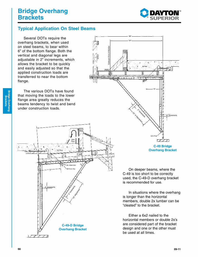
Typical Application On Steel Beams
Several DOTs require the overhang brackets, when used on steel beams, to bear within 6” of the bottom flange. Both the vertical and diagonal legs are adjustable in 2” increments, which allows the bracket to be quickly and easily adjusted so that the applied construction loads are transferred to near the bottom flange.
The various DOTs have found that moving the loads to the lower flange area greatly reduces the beams tendency to twist and bend under construction loads.
On deeper beams, where the C-49 is too short to be correctly used, the C-49-D overhang bracket is recommended for use.
In situations where the overhang is longer than the horizontal members, double 2x lumber can be “cleated” to the bracket.
Either a 6x2 nailed to the horizontal members or double 2x’s are considered part of the bracket design and one or the other must be used at all times.
2" In
crem
ents
22" A
djus
tmen
t
2" Increments
2nd Pour
1st Pour
“A”
A
A
54"
68"
54"
Out
boar
d E
nd o
f B
rack
et
“A”
2" Increments
2" Increments
22" of Adjustment
C-49 Bridge Overhang Bracket
C-49-D Bridge Overhang Bracket

6709-11
®
Bridge Overhang Brackets
Bri
dg
e O
verh
ang
B
rack
ets
Typical Application On Concrete Beams Dayton Superior recommends that brackets bear against the side of the bottom flange on precast concrete girders. This will reduce the number of changes required in setting up the overhang brackets. Allowing 3” to 4” of clearance between the bottom of the vertical leg and the bottom of the concrete eliminates the chance of the concrete spalling due to the construction loads introduced into the girder from the diagonal leg.
C-49-S Field Modified Bridge Overhang Bracket The C-49 Bridge Overhang Bracket is modified in the field by removing the smaller, inner diameter vertical leg and using the larger, outer as the bracket’s vertical leg, as shown. In some cases, due to manufacturing tolerances, the rear spacer, nut and bolt must also be removed and set aside for later re-assembly. Wood blocking is placed on top of the bottom flange, to act as a support for the bracket’s diagonal leg. This allows the lower portion of the vertical leg to run “wild” past the beam’s bottom flange.
C-49-S Bridge Overhang BracketActual Overhang Conditions May Vary
C-49 Bridge Overhang Bracket
3" to 4"
14"
Min
imum
Wood Block
68 09-11
®
Bridge Overhang Brackets
Brid
ge O
verhan
g
Brackets
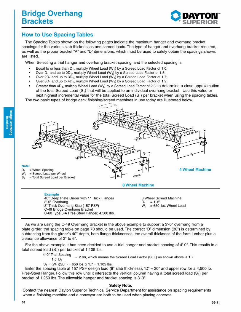
How to Use Spacing TablesThe Spacing Tables shown on the following pages indicate the maximum hanger and overhang bracket
spacings for the various slab thicknesses and screed loads. The type of hanger and overhang bracket required, as well as the proper bracket “A” and “D” dimensions, which must be used to safely obtain the spacings shown, are listed.
When Selecting a trial hanger and overhang bracket spacing; and the selected spacing is:
• Equal to or less than D1, multiply Wheel Load (W1) by a Screed Load Factor of 1.0;• Over D1 and up to 2D1, multiply Wheel Load (W1) by a Screed Load Factor of 1.5;• Over 2D1 and up to 3D1, multiply Wheel Load (W1) by a Screed Load Factor of 1.7;• Over 3D1 and up to 4D1, multiply Wheel Load (W1) by a Screed Load Factor of 1.9;• Greater than 4D1, multiply Wheel Load (W1) by a Screed Load Factor of 2.3; to determine a close approximation
of the total Screed Load (S1) that will be applied to an individual overhang bracket. Use this value or next highest incremental value for the total Screed Load (S1) per bracket when using the spacing tables.
The two basic types of bridge deck finishing/screed machines in use today are illustrated below.
4 Wheel Machine
8 Wheel Machine
Note: D1 = Wheel SpacingW1 = Screed Load per WheelS1 = Total Screed Load per Bracket Varies
Example 40" Deep Plate Girder with 1" Thick Flanges 8 Wheel Screed Machine 3'-0" Overhang D1 = 1'-6" 8" Thick Overhang Slab (157 PSF) W1 = 650 lbs. Wheel Load C-49 Bridge Overhang Bracket C-60 Type 8-A Pres-Steel Hanger, 4,500 lbs.
As we are using the C-49 Overhang Bracket in the above example to support a 3'-0" overhang from a plate girder, the spacing table on page 70 should be used. The correct “D” dimension (30") is determined by subtracting from the girder's 40" depth, both flange thicknesses, the overall thickness of the form lumber plus a clearance allowance of 2" to 6".
For the above example it has been decided to use a trial hanger and bracket spacing of 4'-0". This results in a total screed load (S1) per bracket of 1,105 lbs.
Enter the spacing table at 157 PSF design load (8" slab thickness), “D” = 30" and upper row for a 4,500 lb. Pres-Steel Hanger. Follow this row until it intersects the vertical column having a total screed load (S1) per bracket of 1,250 lbs. The allowable hanger and bracket spacing is 3'-3".
4'-0" Trial Spacing 1.5' D1
= 2.66, which means the Screed Load Factor (SLF) as shown above is 1.7.
S1 = (W1)(SLF) = 650 lbs. x 1.7 = 1,105 lbs.
Safety Note:Contact the nearest Dayton Superior Technical Service Department for assistance on spacing requirements when a finishing machine and a conveyor are both to be used when placing concrete

6909-11
®
Bridge Overhang Brackets
Bri
dg
e O
verh
ang
B
rack
ets
C-49 Bridge Overhang Bracket and Exterior Hanger SpacingOver 1’-0” to 2’-0” Overhangs On Steel Beams Or Girders
3'-10" Maximum
Over 1'-0" to 2'-0"Overhang
"D"
Design Load PSF
Maximum Overhang Thickness
Bracket "D"
Dimension
Screed Load Per Bracket = S1 Hanger SWL Range
(lbs.)2,500 lbs.
2,250 lbs.
2,000 lbs.
1,750 lbs.
1,500 lbs.
1,250 lbs.
1,000 lbs.
0 lbs.
130 6" 30" to 50"
* * * 1' 0" 1' 6" 2' 3" 3' 0" 5' 9" 3,000 to 3,500
1' 9" 2' 6" 3' 3" 3' 9" 4' 6" 5' 3" 6' 0" 8' 0" 4,500 to 5,000
4' 9" 5' 6" 6' 0" 6' 9" 7' 6" 8' 0" 8' 0" 8' 0" 6,000
157 8" 30" to 50"
* * * * 1' 6" 2' 0" 2' 9" 5' 3" 3,000 to 3,500
1' 6" 2' 3" 2' 9" 3' 6" 4' 0" 4' 9" 5' 3" 7' 9" 4,500 to 5,000
4' 3" 4' 9" 5' 6" 6' 0" 6' 9" 7' 3" 8' 0" 8' 0" 6,000
184 10" 30" to 50"
* * * * 1' 3" 1' 9" 2' 6" 4' 9" 3,000 to 3,500
1' 6" 2' 0" 2' 6" 3' 0" 3' 9" 4' 3" 4' 9" 7' 0" 4,500 to 5,000
3' 9" 4' 6" 5' 0" 5' 6" 6' 0" 6' 9" 7' 3" 8' 0" 6,000
210 12" 30" to 50"
* * * * 1' 3" 1' 9" 2' 3" 4' 3" 3,000 to 3,500
1' 3" 1' 9" 2' 3" 2' 9" 3' 3" 4' 0" 4' 6" 6' 6" 4,500 to 5,000
3' 6" 4' 0" 4' 6" 5' 0" 5' 6" 6' 0" 6' 6" 8' 0" 6,000
237 14" 30" to 50"
* * * * 1' 0" 1' 6" 2' 0" 4' 0" 3,000 to 3,500
1' 3" 1' 9" 2' 3" 2' 6" 3' 0" 3' 6" 4' 0" 6' 0" 4,500 to 5,000
3' 3" 3' 9" 4' 3" 4' 9" 5' 3" 5' 6" 6' 0" 8' 0" 6,000
264 16" 30" to 50"
* * * * 1' 0" 1' 6" 1' 9" 3' 9" 3,000 to 3,500
1' 0" 1' 6" 2' 0" 2' 6" 2' 9" 3' 3" 3' 9" 5' 6" 4,500 to 5,000
3' 0" 3' 6" 3' 9" 4' 3" 4' 9" 5' 3" 5' 9" 7' 6" 6,000
290 18" 30" to 50"
* * * * 1' 0" 1' 3" 1' 9" 3' 6" 3,000 to 3,500
1' 0" 1' 6" 1' 9" 2' 3" 2' 9" 3' 0" 3' 6 5' 3" 4,500 to 5,000
2' 9" 3' 3" 3' 6" 4' 0" 4' 6" 4' 9" 5' 3" 7' 0" 6,000
317 20" 30" to 50"
* * * * * 1' 3" 1' 6" 3' 3" 3,000 to 3,500
1' 0" 1' 3" 1' 9" 2' 0" 2' 6" 3' 0" 3' 3" 4' 9" 4,500 to 5,000
2' 6" 3' 0" 3' 3" 3' 9" 4' 3" 4' 6" 5' 0" 6' 6" 6,000
NOTES:1) Design load calculations for the above bracket spacings are based on a dead load of 160 pcf for the concrete and formwork, a live load of 50 psf for workers, moveable equipment and materials, plus a 75 plf vertical load applied at the outside edge of the deck overhang. A 50 psf live load is also applied to the walkway area. 2) Always check overhang form lumber to make certain it will span the selected bracket spacing.3) For a nominal charge, Dayton Superior Technical Service Department will calculate a recommended bracket spacing when conditions on your specific project vary from those shown.
70 09-11
®
Bridge Overhang Brackets
Brid
ge O
verhan
g
Brackets
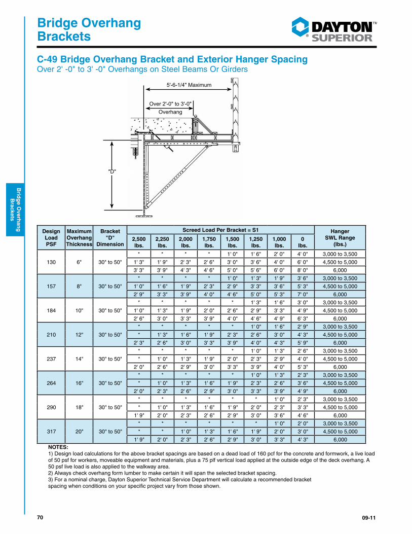
C-49 Bridge Overhang Bracket and Exterior Hanger Spacing Over 2' -0" to 3' -0" Overhangs on Steel Beams Or Girders
5'-6-1/4" Maximum
Over 2'-0" to 3'-0"Overhang
"D"
Design Load PSF
Maximum Overhang Thickness
Bracket "D"
Dimension
Screed Load Per Bracket = S1 Hanger SWL Range
(lbs.)2,500 lbs.
2,250 lbs.
2,000 lbs.
1,750 lbs.
1,500 lbs.
1,250 lbs.
1,000 lbs.
0 lbs.
130 6" 30" to 50"
* * * * 1' 0" 1' 6" 2' 0" 4' 0" 3,000 to 3,500
1' 3" 1' 9" 2' 3" 2' 6" 3' 0" 3' 6" 4' 0" 6' 0" 4,500 to 5,000
3' 3" 3' 9" 4' 3" 4' 6" 5' 0" 5' 6" 6' 0" 8' 0" 6,000
157 8" 30" to 50"
* * * * 1' 0" 1' 3" 1' 9" 3' 6" 3,000 to 3,500
1' 0" 1' 6" 1' 9" 2' 3" 2' 9" 3' 3" 3' 6" 5' 3" 4,500 to 5,000
2' 9" 3' 3" 3' 9" 4' 0" 4' 6" 5' 0" 5' 3" 7' 0" 6,000
184 10" 30" to 50"
* * * * * 1' 3" 1' 6" 3' 0" 3,000 to 3,500
1' 0" 1' 3" 1' 9" 2' 0" 2' 6" 2' 9" 3' 3" 4' 9" 4,500 to 5,000
2' 6" 3' 0" 3' 3" 3' 9" 4' 0" 4' 6" 4' 9" 6' 3" 6,000
210 12" 30" to 50"
* * * * * 1' 0" 1' 6" 2' 9" 3,000 to 3,500
* 1' 3" 1' 6" 1' 9" 2' 3" 2' 6" 3' 0" 4' 3" 4,500 to 5,000
2' 3" 2' 6" 3' 0" 3' 3" 3' 9" 4' 0" 4' 3" 5' 9" 6,000
237 14" 30" to 50"
* * * * * 1' 0" 1' 3" 2' 6" 3,000 to 3,500
* 1' 0" 1' 3" 1' 9" 2' 0" 2' 3" 2' 9" 4' 0" 4,500 to 5,000
2' 0" 2' 6" 2' 9" 3' 0" 3' 3" 3' 9" 4' 0" 5' 3" 6,000
264 16" 30" to 50"
* * * * * 1' 0" 1' 3" 2' 3" 3,000 to 3,500
* 1' 0" 1' 3" 1' 6" 1' 9" 2' 3" 2' 6" 3' 6" 4,500 to 5,000
2' 0" 2' 3" 2' 6" 2' 9" 3' 0" 3' 3" 3' 9" 4' 9" 6,000
290 18" 30" to 50"
* * * * * * 1' 0" 2' 3" 3,000 to 3,500
* 1' 0" 1' 3" 1' 6" 1' 9" 2' 0" 2' 3" 3' 3" 4,500 to 5,000
1' 9" 2' 0" 2' 3" 2' 6" 2' 9" 3' 0" 3' 6" 4' 6" 6,000
317 20" 30" to 50"
* * * * * * 1' 0" 2' 0" 3,000 to 3,500
* * 1' 0" 1' 3" 1' 6" 1' 9" 2' 0" 3' 0" 4,500 to 5,000
1' 9" 2' 0" 2' 3" 2' 6" 2' 9" 3' 0" 3' 3" 4' 3" 6,000 NOTES:1) Design load calculations for the above bracket spacings are based on a dead load of 160 pcf for the concrete and formwork, a live load of 50 psf for workers, moveable equipment and materials, plus a 75 plf vertical load applied at the outside edge of the deck overhang. A 50 psf live load is also applied to the walkway area.2) Always check overhang form lumber to make certain it will span the selected bracket spacing.3) For a nominal charge, Dayton Superior Technical Service Department will calculate a recommended bracketspacing when conditions on your specific project vary from those shown.
7109-11
®
Bridge Overhang Brackets
Bri
dg
e O
verh
ang
B
rack
ets
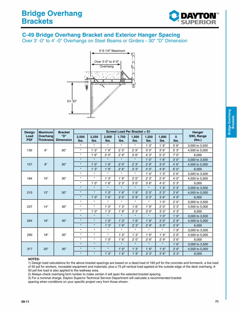
C-49 Bridge Overhang Bracket and Exterior Hanger Spacing Over 3' -0" to 4' -0" Overhangs on Steel Beams or Girders - 30" "D" Dimension
Design Load PSF
Maximum Overhang Thickness
Bracket "D"
Dimension
Screed Load Per Bracket = S1 Hanger SWL Range
(lbs.)2,500 lbs.
2,250 lbs.
2,000 lbs.
1,750 lbs.
1,500 lbs.
1,250 lbs.
1,000 lbs.
0 lbs.
130 6" 30"
* * * * * 1' 3" 1' 9" 3' 6" 3,000 to 3,500
* 1' 3" 1' 9" 2' 3" 2' 9" 3' 0" 3' 6" 5' 3" 4,500 to 5,000
* 1' 6" 2' 0" 2' 9" 3' 6" 4' 3" 5' 3" 7' 0" 6,000
157 8" 30"
* * * * * 1' 0" 1' 6" 3' 0" 3,000 to 3,500
* 1' 0" 1' 6" 2' 0" 2' 3" 2' 9" 3' 0" 4' 6" 4,500 to 5,000
* 1' 3" 1' 9" 2' 6" 3' 3" 4' 0" 4' 6" 6' 0" 6,000
184 10" 30"
* * * * * 1' 0" 1' 3" 2' 6" 3,000 to 3,500
* * 1' 3" 1' 9" 2' 0" 2' 3" 2' 9" 4' 0" 4,500 to 5,000
* 1' 0" 1' 6" 2' 3" 3' 0" 3' 6" 4' 0" 5' 3" 6,000
210 12" 30"
* * * * * * 1' 3" 2' 3" 3,000 to 3,500
* * 1' 0" 1' 6" 1' 9" 2' 0" 2' 3" 3' 6" 4,500 to 5,000
* 1' 0" 1' 6" 2' 0" 2' 9" 3' 3" 3' 6" 4' 9" 6,000
237 14" 30"
* * * * * * 1' 0" 2' 0" 3,000 to 3,500
* * 1' 0" 1' 3" 1' 6" 1' 9" 2' 0" 3' 3" 4,500 to 5,000
* 1' 0" 1' 3" 1' 9" 2' 3" 3' 0" 3' 3" 4' 3" 6,000
264 16" 30"
* * * * * * 1' 0" 1' 9" 3,000 to 3,500
* * 1' 0" 1' 3" 1' 6" 1' 9" 2' 0" 2' 9" 4,500 to 5,000
* * 1' 3" 1' 9" 2' 3" 2' 9" 3' 0" 3' 9" 6,000
290 18" 30"
* * * * * * * 1' 9" 3,000 to 3,500
* * * 1' 0" 1' 3" 1' 6" 1' 9" 2' 6" 4,500 to 5,000
* * 1' 0" 1' 6" 2' 0" 2' 6" 2' 9" 3' 6" 6,000
317 20" 30"
* * * * * * * 1' 6" 3,000 to 3,500
* * * 1' 0" 1' 3" 1' 6" 1' 6" 2' 6" 4,500 to 5,000
* * 1' 0" 1' 6" 1' 9" 2' 3" 2' 6" 3' 3" 6,000
NOTES:1) Design load calculations for the above bracket spacings are based on a dead load of 160 pcf for the concrete and formwork, a live load of 50 psf for workers, moveable equipment and materials, plus a 75 plf vertical load applied at the outside edge of the deck overhang. A 50 psf live load is also applied to the walkway area.2) Always check overhang form lumber to make certain it will span the selected bracket spacing.3) For a nominal charge, Dayton Superior Technical Service Department will calculate a recommended bracketspacing when conditions on your specific project vary from those shown.
5'-6 1/4" Maximum
Over 3'-0" to 4'-0"Overhang
D= 30"

72 09-11
®
Bridge Overhang Brackets
Brid
ge O
verhan
g
Brackets
C-49 Bridge Overhang Bracket and Exterior Hanger SpacingOver 3' -0" to 4' -0" Overhangs On Steel Beams or Girders - 40" to 50" "D" Dimension
Design Load PSF
Maximum Overhang Thickness
Bracket "D"
Dimension
Screed Load Per Bracket = S1 Hanger SWL Range
(lbs.)2,500 lbs.
2,250 lbs.
2,000 lbs.
1,750 lbs.
1,500 lbs.
1,250 lbs.
1,000 lbs.
0 lbs.
130 6" 40" to 50"
* * * * 1' 0" 1' 3" 1' 9" 3' 6" 3,000 to 3,500
1' 0" 1' 6" 1' 9" 2' 3" 2' 9" 3' 0" 3' 6" 5' 3" 4,500 to 5,000
2' 3" 3' 0" 3' 6" 4' 0" 4' 6" 4' 9" 5' 3" 7' 0" 6,000
157 8" 40" to 50"
* * * * * 1' 0" 1' 6" 3' 0" 3,000 to 3,500
* 1' 3" 1' 6" 2' 0" 2' 3" 2' 9" 3' 0" 4' 6" 4,500 to 5,000
2' 0" 2' 9" 3' 0" 3' 6" 3' 9" 4' 3" 4' 6" 6' 0" 6,000
184 10" 40" to 50"
* * * * * 1' 0" 1' 3" 2' 6" 3,000 to 3,500
* 1' 0" 1' 3" 1' 9" 2' 0" 2' 3" 2' 9" 4' 0" 4,500 to 5,000
1' 9" 2' 6" 2' 9" 3' 0" 3' 3" 3' 9" 4' 0" 5' 3" 6,000
210 12" 40" to 50"
* * * * * * 1' 3" 2' 3" 3,000 to 3,500
* 1' 0" 1' 3" 1' 6" 1' 9" 2' 0" 2' 3" 3' 6" 4,500 to 5,000
1' 9" 2' 3" 2' 6" 2' 9" 3' 0" 3' 3" 3' 6" 4' 9" 6,000
237 14" 40" to 50"
* * * * * * 1' 0" 2' 0" 3,000 to 3,500
* * 1' 0" 1' 3" 1' 6" 1' 9" 2' 0" 3' 3" 4,500 to 5,000
1' 6" 2' 0" 2' 3" 2' 6" 2' 9" 3' 0" 3' 3" 4' 3" 6,000
264 16" 40" to 50"
* * * * * * 1' 0" 1' 9" 3,000 to 3,500
* * 1' 0" 1' 3" 1' 6" 1' 9" 2' 0" 2' 9" 4,500 to 5,000
1' 6" 1' 9" 2' 0" 2' 3" 2' 6" 2' 9" 3' 0" 3' 9" 6,000
290 18" 40" to 50"
* * * * * * * 1' 9" 3,000 to 3,500
* * 1' 0" 1' 0" 1' 3" 1' 6" 1' 9" 2' 6" 4,500 to 5,000
1' 3" 1' 6" 1' 9" 2' 0" 2' 3" 2' 6" 2' 9" 3' 6" 6,000
317 20" 40" to 50"
* * * * * * * 1' 6" 3,000 to 3,500
* * * 1' 0" 1' 3" 1' 6" 1' 6" 2' 6" 4,500 to 5,000
1' 3" 1' 6" 1' 9" 1' 9" 2' 0" 2' 3" 2' 6" 3' 3" 6,000
NOTES:1) Design load calculations for the above bracket spacings are based on a dead load of 160 pcf for the concrete and formwork, a live load of 50 psf for workers, moveable equipment and materials, plus a 75 plf vertical load applied at the outside edge of the deck overhang. A 50 psf live load is also applied to the walkway area.2) Always check overhang form lumber to make certain it will span the selected bracket spacing.3) For a nominal charge, Dayton Superior Technical Service Department will calculate a recommended bracketspacing when conditions on your specific project vary from those shown.
5'-6 1/4" Maximum
Over 3'-0" to 4'-0"Overhang
D= 40" - 50"

7309-11
®
Bridge Overhang Brackets
Bri
dg
e O
verh
ang
B
rack
ets
C-49 Bridge Overhang Bracket and Exterior Hanger Spacing Over 1’-0” to 2’-0” Overhangs On Precast/Prestressed Concrete Girders
Design Load PSF
Maximum Overhang Thickness
Bracket "D"
Dimension
Screed Load Per Bracket = S1Hanger
SWL Range (lbs.)2,500 lbs.
2,250 lbs.
2,000 lbs.
1,750 lbs.
1,500 lbs.
1,250 lbs.
1,000 lbs.
0 lbs.
130 6" 30" to 50"
* * * * 1' 3" 2' 0" 2' 6" 4' 9" 3,000 to 3,500
1' 6" 2' 0" 2' 9" 3' 3" 3' 9" 4' 6" 5' 0" 7' 3" 4,500 to 5,000
4' 0" 4' 6" 5' 3" 5' 9" 6' 3" 7' 0" 7' 6" 8' 0" 6,000
157 8" 30" to 50"
* * * * 1' 3" 1' 9" 2' 3" 4' 3" 3,000 to 3,500
1' 3" 1' 9" 2' 3" 2' 9" 3' 6" 4' 0" 4' 6" 6' 6" 4,500 to 5,000
3' 6" 4' 0" 4' 6" 5' 0" 5' 6" 6' 0" 6' 9" 8' 0" 6,000
184 10" 30" to 50"
* * * * 1' 0" 1' 6" 2' 0" 3' 9" 3,000 to 3,500
1' 3" 1' 6" 2' 0" 2' 6" 3' 0" 3' 6" 4' 0" 5' 9" 4,500 to 5,000
3' 3" 3' 6" 4' 0" 4' 6" 5' 0" 5' 6" 6' 0" 7' 9" 6,000
210 12" 30" to 50"
* * * * 1' 0" 1' 3" 1' 9" 3' 6" 3,000 to 3,500
1' 0" 1' 6" 2' 0" 2' 3" 2' 9" 3' 3" 3' 6" 5' 3" 4,500 to 5,000
2' 9" 3' 3" 3' 9" 4' 0" 4' 6" 5' 0" 5' 6" 7' 0" 6,000
237 14" 30" to 50"
* * * * * 1' 3" 1' 9" 3' 3" 3,000 to 3,500
1' 0" 1' 3" 1' 9" 2' 0" 2' 6" 3' 0" 3' 3" 4' 9" 4,500 to 5,000
2' 6" 3' 0" 3' 6" 3' 9" 4' 3" 4' 6" 5' 0" 6' 6" 6,000
264 16" 30" to 50"
* * * * * 1' 3" 1' 6" 3' 0" 3,000 to 3,500
* 1' 3" 1' 6" 2' 0" 2' 3" 2' 9" 3' 0" 4' 6" 4,500 to 5,000
2' 6" 2' 9" 3' 0" 3' 6" 3' 9" 4' 3" 4' 6" 6' 0" 6,000
290 18" 30" to 50"
* * * * * 1' 0" 1' 6" 2' 9" 3,000 to 3,500
* 1' 0" 1' 6" 1' 9" 2' 3" 2' 6" 2' 9" 4' 3" 4,500 to 5,000
2' 3" 2' 6" 3' 0" 3' 3" 3' 6" 4' 0" 4' 3" 5' 6" 6,000
317 20" 30" to 50"
* * * * * 1' 0" 1' 3" 2' 6" 3,000 to 3,500
* 1' 0" 1' 3" 1' 9" 2' 0" 2' 3" 2' 6" 3' 9" 4,500 to 5,000
2' 0" 2' 3" 2' 9" 3' 0" 3' 3" 3' 6" 4' 0" 5' 3" 6,000
NOTES:1) Design load calculations for the above bracket spacings are based on a dead load of 160 pcf for the concrete and formwork, a live load of 50 psf for workers, moveable equipment and materials, plus a 75 plf vertical load applied at the outside edge of the deck overhang. A 50 psf live load is also applied to the walkway area. 2) Always check overhang form lumber to make certain it will span the selected bracket spacing.3) For a nominal charge, Dayton Superior Technical Service Department will calculate a recommended bracket spacing when conditions on yourspecificprojectvaryfromthoseshown.
3'- 10" Maximum
Over 1'-0" to 2'-0"Overhang
"D"
74 09-11
®
Bridge Overhang Brackets
Brid
ge O
verhan
g
Brackets
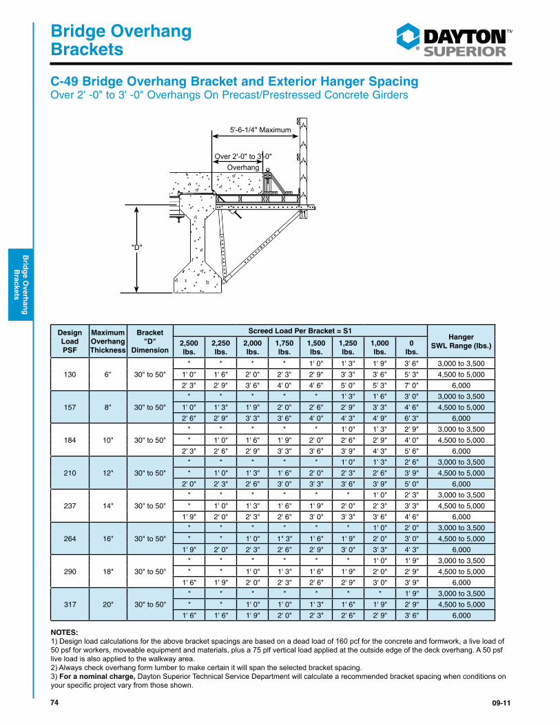
C-49 Bridge Overhang Bracket and Exterior Hanger Spacing Over 2' -0" to 3' -0" Overhangs On Precast/Prestressed Concrete Girders
5'-6-1/4" Maximum
Over 2'-0" to 3'-0"Overhang
"D"
Design Load PSF
Maximum Overhang Thickness
Bracket "D"
Dimension
Screed Load Per Bracket = S1Hanger
SWL Range (lbs.)2,500 lbs.
2,250 lbs.
2,000 lbs.
1,750 lbs.
1,500 lbs.
1,250 lbs.
1,000 lbs.
0 lbs.
130 6" 30" to 50"
* * * * 1' 0" 1' 3" 1' 9" 3' 6" 3,000 to 3,500
1' 0" 1' 6" 2' 0" 2' 3" 2' 9" 3' 3" 3' 6" 5' 3" 4,500 to 5,000
2' 3" 2' 9" 3' 6" 4' 0" 4' 6" 5' 0" 5' 3" 7' 0" 6,000
157 8" 30" to 50"
* * * * * 1' 3" 1' 6" 3' 0" 3,000 to 3,500
1' 0" 1' 3" 1' 9" 2' 0" 2' 6" 2' 9" 3' 3" 4' 6" 4,500 to 5,000
2' 6" 2' 9" 3' 3" 3' 6" 4' 0" 4' 3" 4' 9" 6' 3" 6,000
184 10" 30" to 50"
* * * * * 1' 0" 1' 3" 2' 9" 3,000 to 3,500
* 1' 0" 1' 6" 1' 9" 2' 0" 2' 6" 2' 9" 4' 0" 4,500 to 5,000
2' 3" 2' 6" 2' 9" 3' 3" 3' 6" 3' 9" 4' 3" 5' 6" 6,000
210 12" 30" to 50"
* * * * * 1' 0" 1' 3" 2' 6" 3,000 to 3,500
* 1' 0" 1' 3" 1' 6" 2' 0" 2' 3" 2' 6" 3' 9" 4,500 to 5,000
2' 0" 2' 3" 2' 6" 3' 0" 3' 3" 3' 6" 3' 9" 5' 0" 6,000
237 14" 30" to 50"
* * * * * * 1' 0" 2' 3" 3,000 to 3,500
* 1' 0" 1' 3" 1' 6" 1' 9" 2' 0" 2' 3" 3' 3" 4,500 to 5,000
1' 9" 2' 0" 2' 3" 2' 6" 3' 0" 3' 3" 3' 6" 4' 6" 6,000
264 16" 30" to 50"
* * * * * * 1' 0" 2' 0" 3,000 to 3,500
* * 1' 0" 1" 3" 1' 6" 1' 9" 2' 0" 3' 0" 4,500 to 5,000
1' 9" 2' 0" 2' 3" 2' 6" 2' 9" 3' 0" 3' 3" 4' 3" 6,000
290 18" 30" to 50"
* * * * * * 1' 0" 1' 9" 3,000 to 3,500
* * 1' 0" 1' 3" 1' 6" 1' 9" 2' 0" 2' 9" 4,500 to 5,000
1' 6" 1' 9" 2' 0" 2' 3" 2' 6" 2' 9" 3' 0" 3' 9" 6,000
317 20" 30" to 50"
* * * * * * * 1' 9" 3,000 to 3,500
* * 1' 0" 1' 0" 1' 3" 1' 6" 1' 9" 2' 9" 4,500 to 5,000
1' 6" 1' 6" 1' 9" 2' 0" 2' 3" 2' 6" 2' 9" 3' 6" 6,000
NOTES:1) Design load calculations for the above bracket spacings are based on a dead load of 160 pcf for the concrete and formwork, a live load of 50 psf for workers, moveable equipment and materials, plus a 75 plf vertical load applied at the outside edge of the deck overhang. A 50 psf live load is also applied to the walkway area. 2) Always check overhang form lumber to make certain it will span the selected bracket spacing.3) For a nominal charge, Dayton Superior Technical Service Department will calculate a recommended bracket spacing when conditions on yourspecificprojectvaryfromthoseshown.
7509-11
®
Bridge Overhang Brackets
Bri
dg
e O
verh
ang
B
rack
ets
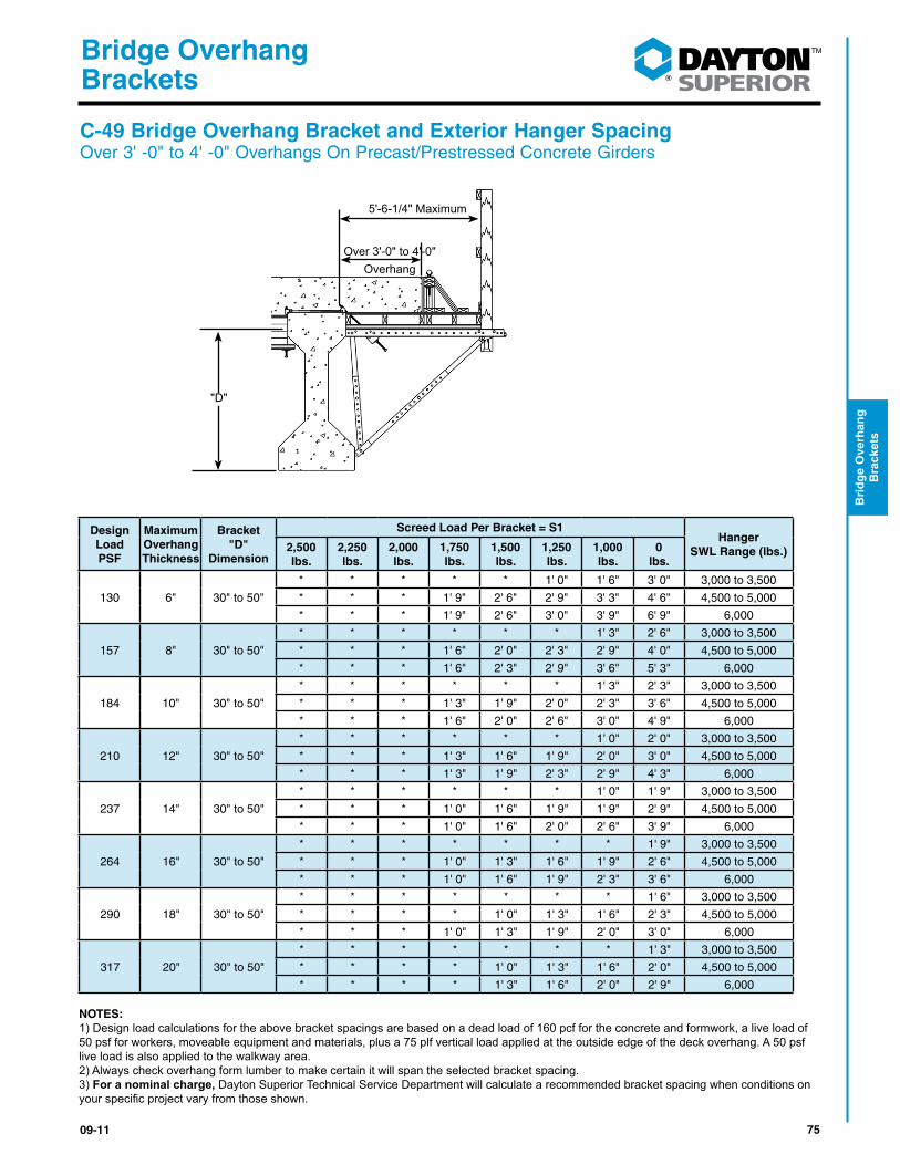
C-49 Bridge Overhang Bracket and Exterior Hanger Spacing Over 3' -0" to 4' -0" Overhangs On Precast/Prestressed Concrete Girders
5'-6-1/4" Maximum
Over 3'-0" to 4'-0"Overhang
"D"
Design Load PSF
Maximum Overhang Thickness
Bracket "D"
Dimension
Screed Load Per Bracket = S1Hanger
SWL Range (lbs.)2,500 lbs.
2,250 lbs.
2,000 lbs.
1,750 lbs.
1,500 lbs.
1,250 lbs.
1,000 lbs.
0 lbs.
130 6" 30" to 50"
* * * * * 1' 0" 1' 6" 3' 0" 3,000 to 3,500
* * * 1' 9" 2' 6" 2' 9" 3' 3" 4' 6" 4,500 to 5,000
* * * 1' 9" 2' 6" 3' 0" 3' 9" 6' 9" 6,000
157 8" 30" to 50"
* * * * * * 1' 3" 2' 6" 3,000 to 3,500
* * * 1' 6" 2' 0" 2' 3" 2' 9" 4' 0" 4,500 to 5,000
* * * 1' 6" 2' 3" 2' 9" 3' 6" 5' 3" 6,000
184 10" 30" to 50"
* * * * * * 1' 3" 2' 3" 3,000 to 3,500
* * * 1' 3" 1' 9" 2' 0" 2' 3" 3' 6" 4,500 to 5,000
* * * 1' 6" 2' 0" 2' 6" 3' 0" 4' 9" 6,000
210 12" 30" to 50"
* * * * * * 1' 0" 2' 0" 3,000 to 3,500
* * * 1' 3" 1' 6" 1' 9" 2' 0" 3' 0" 4,500 to 5,000
* * * 1' 3" 1' 9" 2' 3" 2' 9" 4' 3" 6,000
237 14" 30" to 50"
* * * * * * 1' 0" 1' 9" 3,000 to 3,500
* * * 1' 0" 1' 6" 1' 9" 1' 9" 2' 9" 4,500 to 5,000
* * * 1' 0" 1' 6" 2' 0" 2' 6" 3' 9" 6,000
264 16" 30" to 50"
* * * * * * * 1' 9" 3,000 to 3,500
* * * 1' 0" 1' 3" 1' 6" 1' 9" 2' 6" 4,500 to 5,000
* * * 1' 0" 1' 6" 1' 9" 2' 3" 3' 6" 6,000
290 18" 30" to 50"
* * * * * * * 1' 6" 3,000 to 3,500
* * * * 1' 0" 1' 3" 1' 6" 2' 3" 4,500 to 5,000
* * * 1' 0" 1' 3" 1' 9" 2' 0" 3' 0" 6,000
317 20" 30" to 50"
* * * * * * * 1' 3" 3,000 to 3,500
* * * * 1' 0" 1' 3" 1' 6" 2' 0" 4,500 to 5,000
* * * * 1' 3" 1' 6" 2' 0" 2' 9" 6,000
NOTES:1) Design load calculations for the above bracket spacings are based on a dead load of 160 pcf for the concrete and formwork, a live load of 50 psf for workers, moveable equipment and materials, plus a 75 plf vertical load applied at the outside edge of the deck overhang. A 50 psf live load is also applied to the walkway area. 2) Always check overhang form lumber to make certain it will span the selected bracket spacing.3) For a nominal charge, Dayton Superior Technical Service Department will calculate a recommended bracket spacing when conditions on yourspecificprojectvaryfromthoseshown.

76 09-11
®
Bridge Overhang Brackets
Brid
ge O
verhan
g
Brackets
C-49-D Bridge Overhang Bracket and Exterior Hanger Spacing Over 1’-0” to 2’-0” Overhangs on Steel Beams or Girders
3'- 10" Maximum
Over 1'-0" to 2'-0"Overhang
"D"
Design Load PSF
Maximum Overhang Thickness
Bracket "D"
Dimension
Screed Load Per Bracket = S1Hanger
SWL Range (lbs.)2,500 lbs.
2,250 lbs.
2,000 lbs.
1,750 lbs.
1,500 lbs.
1,250 lbs.
1,000 lbs.
0 lbs.
130 6" 50" to 70"
* * * 1' 0" 1' 6" 2' 3" 3' 0" 5' 9" 3,000 to 3,500
1' 9" 2' 6" 3' 3" 3' 9" 4' 6" 5' 3" 6' 0" 8' 0" 4,500 to 5,000
4' 9" 5' 6" 6' 0" 6' 9" 7' 6" 8' 0" 8' 0" 8' 0" 6,000
157 8" 50" to 70"
* * * * 1' 6" 2' 0" 2' 9" 5' 3" 3,000 to 3,500
1' 6" 2' 3" 2' 9" 3' 6" 4' 0" 4' 9" 5' 3" 7' 9" 4,500 to 5,000
4' 3" 4' 9" 5' 6" 6' 0" 6' 9" 7' 3" 8' 0" 8' 0" 6,000
184 10" 50" to 70"
* * * * 1' 3" 1' 9" 2' 6" 4' 9" 3,000 to 3,500
1' 6" 2' 0" 2' 6" 3' 0" 3' 9" 4' 3" 4' 9" 7' 0" 4,500 to 5,000
3' 9" 4' 6" 5' 0" 5' 6" 6' 0" 6' 9" 7' 3" 8' 0" 6,000
210 12" 50" to 70"
* * * * 1' 3" 1' 9" 2' 3" 4' 3" 3,000 to 3,500
1' 3" 1' 9" 2' 3" 2' 9" 3' 3" 4' 0" 4' 6" 6' 6" 4,500 to 5,000
3' 6" 4' 0" 4' 6" 5' 0" 5' 6" 6' 0" 6' 6" 8' 0" 6,000
237 14" 50" to 70"
* * * * 1' 0" 1' 6" 2' 0" 4' 0" 3,000 to 3,500
1' 3" 1' 9" 2' 3" 2' 6" 3' 0" 3' 6" 4' 0" 6' 0" 4,500 to 5,000
3' 3" 3' 9" 4' 3" 4' 9" 5' 3" 5' 6" 6' 0" 8' 0" 6,000
264 16" 50" to 70"
* * * * 1' 0" 1' 6" 1' 9" 3' 9" 3,000 to 3,500
1' 0" 1' 6" 2' 0" 2' 6" 2' 9" 3' 3" 3' 9" 5' 6" 4,500 to 5,000
3' 0" 3' 6" 3' 9" 4' 3" 4' 9" 5' 3" 5' 9" 7' 6" 6,000
290 18" 50" to 70"
* * * * 1' 0" 1' 3" 1' 9" 3' 6" 3,000 to 3,500
1' 0" 1' 6" 1' 9" 2' 3" 2' 9" 3' 0" 3' 6 5' 3" 4,500 to 5,000
2' 9" 3' 3" 3' 6" 4' 0" 4' 6" 4' 9" 5' 3" 7' 0" 6,000
317 20" 50" to 70"
* * * * * 1' 3" 1' 6" 3' 3" 3,000 to 3,500
1' 0" 1' 3" 1' 9" 2' 0" 2' 6" 3' 0" 3' 3" 4' 9" 4,500 to 5,000
2' 6" 3' 0" 3' 3" 3' 9" 4' 3" 4' 6" 5' 0" 6' 6" 6,000
NOTES:1) Design load calculations for the above bracket spacings are based on a dead load of 160 pcf for the concrete and formwork, a live load of 50 psf for workers, moveable equipment and materials, plus a 75 plf vertical load applied at the outside edge of the deck overhang. A 50 psf live load is also applied to the walkway area. 2) Always check overhang form lumber to make certain it will span the selected bracket spacing.3) For a nominal charge, Dayton Superior Technical Service Department will calculate a recommended bracket spacing when conditions on yourspecificprojectvaryfromthoseshown.
7709-11
®
Bridge Overhang Brackets
Bri
dg
e O
verh
ang
B
rack
ets
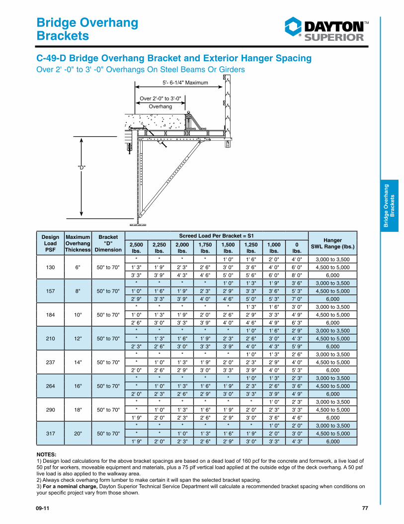
C-49-D Bridge Overhang Bracket and Exterior Hanger SpacingOver 2' -0" to 3' -0" Overhangs On Steel Beams Or Girders
5'- 6-1/4" Maximum
Over 2'-0" to 3'-0"Overhang
"D"
Design Load PSF
Maximum Overhang Thickness
Bracket "D"
Dimension
Screed Load Per Bracket = S1Hanger
SWL Range (lbs.)2,500 lbs.
2,250 lbs.
2,000 lbs.
1,750 lbs.
1,500 lbs.
1,250 lbs.
1,000 lbs.
0 lbs.
130 6" 50" to 70"
* * * * 1' 0" 1' 6" 2' 0" 4' 0" 3,000 to 3,500
1' 3" 1' 9" 2' 3" 2' 6" 3' 0" 3' 6" 4' 0" 6' 0" 4,500 to 5,000
3' 3" 3' 9" 4' 3" 4' 6" 5' 0" 5' 6" 6' 0" 8' 0" 6,000
157 8" 50" to 70"
* * * * 1' 0" 1' 3" 1' 9" 3' 6" 3,000 to 3,500
1' 0" 1' 6" 1' 9" 2' 3" 2' 9" 3' 3" 3' 6" 5' 3" 4,500 to 5,000
2' 9" 3' 3" 3' 9" 4' 0" 4' 6" 5' 0" 5' 3" 7' 0" 6,000
184 10" 50" to 70"
* * * * * 1' 3" 1' 6" 3' 0" 3,000 to 3,500
1' 0" 1' 3" 1' 9" 2' 0" 2' 6" 2' 9" 3' 3" 4' 9" 4,500 to 5,000
2' 6" 3' 0" 3' 3" 3' 9" 4' 0" 4' 6" 4' 9" 6' 3" 6,000
210 12" 50" to 70"
* * * * * 1' 0" 1' 6" 2' 9" 3,000 to 3,500
* 1' 3" 1' 6" 1' 9" 2' 3" 2' 6" 3' 0" 4' 3" 4,500 to 5,000
2' 3" 2' 6" 3' 0" 3' 3" 3' 9" 4' 0" 4' 3" 5' 9" 6,000
237 14" 50" to 70"
* * * * * 1' 0" 1' 3" 2' 6" 3,000 to 3,500
* 1' 0" 1' 3" 1' 9" 2' 0" 2' 3" 2' 9" 4' 0" 4,500 to 5,000
2' 0" 2' 6" 2' 9" 3' 0" 3' 3" 3' 9" 4' 0" 5' 3" 6,000
264 16" 50" to 70"
* * * * * 1' 0" 1' 3" 2' 3" 3,000 to 3,500
* 1' 0" 1' 3" 1' 6" 1' 9" 2' 3" 2' 6" 3' 6" 4,500 to 5,000
2' 0" 2' 3" 2' 6" 2' 9" 3' 0" 3' 3" 3' 9" 4' 9" 6,000
290 18" 50" to 70"
* * * * * * 1' 0" 2' 3" 3,000 to 3,500
* 1' 0" 1' 3" 1' 6" 1' 9" 2' 0" 2' 3" 3' 3" 4,500 to 5,000
1' 9" 2' 0" 2' 3" 2' 6" 2' 9" 3' 0" 3' 6" 4' 6" 6,000
317 20" 50" to 70"
* * * * * * 1' 0" 2' 0" 3,000 to 3,500
* * 1' 0" 1' 3" 1' 6" 1' 9" 2' 0" 3' 0" 4,500 to 5,000
1' 9" 2' 0" 2' 3" 2' 6" 2' 9" 3' 0" 3' 3" 4' 3" 6,000
NOTES:1) Design load calculations for the above bracket spacings are based on a dead load of 160 pcf for the concrete and formwork, a live load of 50 psf for workers, moveable equipment and materials, plus a 75 plf vertical load applied at the outside edge of the deck overhang. A 50 psf live load is also applied to the walkway area. 2) Always check overhang form lumber to make certain it will span the selected bracket spacing.3) For a nominal charge, Dayton Superior Technical Service Department will calculate a recommended bracket spacing when conditions on yourspecificprojectvaryfromthoseshown.

78 09-11
®
Bridge Overhang Brackets
Brid
ge O
verhan
g
Brackets
C-49-D Bridge Overhang Bracket and Exterior Hanger SpacingOver 3' -0" to 4' -0" Overhangs On Steel Beams or Girders
5'- 6-1/4" Maximum
Over 3'-0" to 4'-0"Overhang
"D"
Design Load PSF
Maximum Overhang Thickness
Bracket "D"
Dimension
Screed Load Per Bracket = S1Hanger
SWL Range (lbs.)2,500 lbs.
2,250 lbs.
2,000 lbs.
1,750 lbs.
1,500 lbs.
1,250 lbs.
1,000 lbs.
0 lbs.
130 6" 50" to 70"
* * * * * 1' 3" 1' 9" 3' 6" 3,000 to 3,500
1' 0" 1' 6" 1' 9" 2' 3" 2' 9" 3' 0" 3' 6" 5' 3" 4,500 to 5,000
2' 9" 3' 3" 3' 6" 4' 0" 4' 6" 4' 9" 5' 3" 7' 0" 6,000
157 8" 50" to 70"
* * * * * 1' 0" 1' 6" 3' 0" 3,000 to 3,500
* 1' 3" 1' 6" 2' 0" 2' 3" 2' 9" 3' 0" 4' 6" 4,500 to 5,000
2' 3" 2' 9" 3' 0" 3' 6" 3' 9" 4' 3" 4' 6" 6' 0" 6,000
184 10" 50" to 70"
* * * * * 1' 0" 1' 3" 2' 6" 3,000 to 3,500
* 1' 0" 1' 3" 1' 9" 2' 0" 2' 3" 2' 9" 4' 0" 4,500 to 5,000
2' 0" 2' 6" 2' 9" 3' 0" 3' 6" 3' 9" 4' 0" 5' 3" 6,000
210 12" 50" to 70"
* * * * * * 1' 3" 2' 3" 3,000 to 3,500
* 1' 0" 1' 3" 1' 6" 1' 9" 2' 0" 2' 3" 3' 6" 4,500 to 5,000
1' 9" 2' 3" 2' 6" 2' 9" 3' 0" 3' 3" 3' 6" 4' 9" 6,000
237 14" 50" to 70"
* * * * * * 1' 0" 2' 0" 3,000 to 3,500
* * 1' 0" 1' 3" 1' 6" 1' 9" 2' 0" 3' 3" 4,500 to 5,000
1' 9" 2' 0" 2' 3" 2' 6" 2' 9" 3' 0" 3' 3" 4' 3" 6,000
264 16" 50" to 70"
* * * * * * 1' 0" 1' 9" 3,000 to 3,500
* * 1' 0" 1' 3" 1' 6" 1' 9" 2' 0" 2' 9" 4,500 to 5,000
1' 6" 1' 9" 2' 0" 2' 3" 2' 6" 2' 9" 3' 0" 3' 9" 6,000
290 18" 50" to 70"
* * * * * * * 1' 9" 3,000 to 3,500
* * * 1' 0" 1' 3" 1' 6" 1' 9" 2' 6" 4,500 to 5,000
1' 3" 1' 6" 1' 9" 2' 0" 2' 3" 2' 6" 2' 9" 3' 6" 6,000
317 20" 50" to 70"
* * * * * * * 1' 6" 3,000 to 3,500
* * * 1' 0" 1' 3" 1' 6" 1' 6" 2' 6" 4,500 to 5,000
1' 3" 1' 6" 1' 9" 1' 9" 2' 0" 2' 3" 2' 6" 3' 3" 6,000
NOTES:1) Design load calculations for the above bracket spacings are based on a dead load of 160 pcf for the concrete and formwork, a live load of 50 psf for workers, moveable equipment and materials, plus a 75 plf vertical load applied at the outside edge of the deck overhang. A 50 psf live load is also applied to the walkway area. 2) Always check overhang form lumber to make certain it will span the selected bracket spacing.3) For a nominal charge, Dayton Superior Technical Service Department will calculate a recommended bracket spacing when conditions on yourspecificprojectvaryfromthoseshown.

7909-11
®
Bridge Overhang Brackets
Bri
dg
e O
verh
ang
B
rack
ets
C-49-D Bridge Overhang Bracket and Exterior Hanger SpacingOver 1’-0” to 2’-0” Overhangs On Precast/Prestressed Concrete Girders
Design Load PSF
Maximum Overhang Thickness
Bracket "D"
Dimension
Screed Load Per Bracket = S1Hanger
SWL Range (lbs.)2,500 lbs.
2,250 lbs.
2,000 lbs.
1,750 lbs.
1,500 lbs.
1,250 lbs.
1,000 lbs.
0 lbs.
130 6" 50" to 70"
* * * * 1' 3" 2' 0" 2' 6" 4' 9" 3,000 to 3,500
1' 6" 2' 0" 2' 9" 3' 3" 3' 9" 4' 6" 5' 0" 7' 3" 4,500 to 5,000
4' 0" 4' 6" 5' 3" 5' 9" 6' 3" 7' 0" 7' 6" 8' 0" 6,000
157 8" 50" to 70"
* * * * 1' 3" 1' 9" 2' 3" 4' 3" 3,000 to 3,500
1' 3" 1' 9" 2' 3" 2' 9" 3' 6" 4' 0" 4' 6" 6' 6" 4,500 to 5,000
3' 6" 4' 0" 4' 6" 5' 0" 5' 6" 6' 0" 6' 9" 8' 0" 6,000
184 10" 50" to 70"
* * * * 1' 0" 1' 6" 2' 0" 3' 9" 3,000 to 3,500
1' 3" 1' 6" 2' 0" 2' 6" 3' 0" 3' 6" 4' 0" 5' 9" 4,500 to 5,000
3' 3" 3' 6" 4' 0" 4' 6" 5' 0" 5' 6" 6' 0" 7' 9" 6,000
210 12" 50" to 70"
* * * * 1' 0" 1' 3" 1' 9" 3' 6" 3,000 to 3,500
1' 0" 1' 6" 2' 0" 2' 3" 2' 9" 3' 3" 3' 6" 5' 3" 4,500 to 5,000
2' 9" 3' 3" 3' 9" 4' 0" 4' 6" 5' 0" 5' 6" 7' 0" 6,000
237 14" 50" to 70"
* * * * * 1' 3" 1' 9" 3' 3" 3,000 to 3,500
1' 0" 1' 3" 1' 9" 2' 0" 2' 6" 3' 0" 3' 3" 4' 9" 4,500 to 5,000
2' 6" 3' 0" 3' 6" 3' 9" 4' 3" 4' 6" 5' 0" 6' 6" 6,000
264 16" 50" to 70"
* * * * * 1' 3" 1' 6" 3' 0" 3,000 to 3,500
* 1' 3" 1' 6" 2' 0" 2' 3" 2' 9" 3' 0" 4' 6" 4,500 to 5,000
2' 6" 2' 9" 3' 0" 3' 6" 3' 9" 4' 3" 4' 6" 6' 0" 6,000
290 18" 50" to 70"
* * * * * 1' 0" 1' 6" 2' 9" 3,000 to 3,500
* 1' 0" 1' 6" 1' 9" 2' 3" 2' 6" 2' 9" 4' 3" 4,500 to 5,000
2' 3" 2' 6" 3' 0" 3' 3" 3' 6" 4' 0" 4' 3" 5' 6" 6,000
317 20" 50" to 70"
* * * * * 1' 0" 1' 3" 2' 6" 3,000 to 3,500
* 1' 0" 1' 3" 1' 9" 2' 0" 2' 3" 2' 6" 3' 9" 4,500 to 5,000
2' 0" 2' 3" 2' 9" 3' 0" 3' 3" 3' 6" 4' 0" 5' 3" 6,000
NOTES:1) Design load calculations for the above bracket spacings are based on a dead load of 160 pcf for the concrete and formwork, a live load of 50 psf for workers, moveable equipment and materials, plus a 75 plf vertical load applied at the outside edge of the deck overhang. A 50 psf live load is also applied to the walkway area. 2) Always check overhang form lumber to make certain it will span the selected bracket spacing.3) For a nominal charge, Dayton Superior Technical Service Department will calculate a recommended bracket spacing when conditions onyourspecificprojectvaryfromthoseshown.
3'- 10" Maximum
Over 1'-0" to 2'-0"Overhang
"D"
80 09-11
®
Bridge Overhang Brackets
Brid
ge O
verhan
g
Brackets
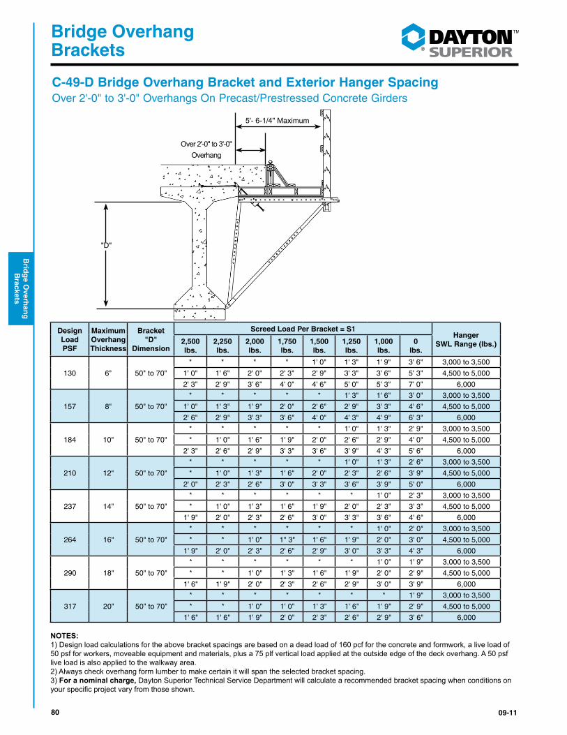
C-49-D Bridge Overhang Bracket and Exterior Hanger SpacingOver 2'-0" to 3'-0" Overhangs On Precast/Prestressed Concrete Girders
5'- 6-1/4" Maximum
Over 2'-0" to 3'-0"Overhang
"D"
Design Load PSF
Maximum Overhang Thickness
Bracket "D"
Dimension
Screed Load Per Bracket = S1Hanger
SWL Range (lbs.)2,500 lbs.
2,250 lbs.
2,000 lbs.
1,750 lbs.
1,500 lbs.
1,250 lbs.
1,000 lbs.
0 lbs.
130 6" 50" to 70"
* * * * 1' 0" 1' 3" 1' 9" 3' 6" 3,000 to 3,500
1' 0" 1' 6" 2' 0" 2' 3" 2' 9" 3' 3" 3' 6" 5' 3" 4,500 to 5,000
2' 3" 2' 9" 3' 6" 4' 0" 4' 6" 5' 0" 5' 3" 7' 0" 6,000
157 8" 50" to 70"
* * * * * 1' 3" 1' 6" 3' 0" 3,000 to 3,500
1' 0" 1' 3" 1' 9" 2' 0" 2' 6" 2' 9" 3' 3" 4' 6" 4,500 to 5,000
2' 6" 2' 9" 3' 3" 3' 6" 4' 0" 4' 3" 4' 9" 6' 3" 6,000
184 10" 50" to 70"
* * * * * 1' 0" 1' 3" 2' 9" 3,000 to 3,500
* 1' 0" 1' 6" 1' 9" 2' 0" 2' 6" 2' 9" 4' 0" 4,500 to 5,000
2' 3" 2' 6" 2' 9" 3' 3" 3' 6" 3' 9" 4' 3" 5' 6" 6,000
210 12" 50" to 70"
* * * * * 1' 0" 1' 3" 2' 6" 3,000 to 3,500
* 1' 0" 1' 3" 1' 6" 2' 0" 2' 3" 2' 6" 3' 9" 4,500 to 5,000
2' 0" 2' 3" 2' 6" 3' 0" 3' 3" 3' 6" 3' 9" 5' 0" 6,000
237 14" 50" to 70"
* * * * * * 1' 0" 2' 3" 3,000 to 3,500
* 1' 0" 1' 3" 1' 6" 1' 9" 2' 0" 2' 3" 3' 3" 4,500 to 5,000
1' 9" 2' 0" 2' 3" 2' 6" 3' 0" 3' 3" 3' 6" 4' 6" 6,000
264 16" 50" to 70"
* * * * * * 1' 0" 2' 0" 3,000 to 3,500
* * 1' 0" 1" 3" 1' 6" 1' 9" 2' 0" 3' 0" 4,500 to 5,000
1' 9" 2' 0" 2' 3" 2' 6" 2' 9" 3' 0" 3' 3" 4' 3" 6,000
290 18" 50" to 70"
* * * * * * 1' 0" 1' 9" 3,000 to 3,500
* * 1' 0" 1' 3" 1' 6" 1' 9" 2' 0" 2' 9" 4,500 to 5,000
1' 6" 1' 9" 2' 0" 2' 3" 2' 6" 2' 9" 3' 0" 3' 9" 6,000
317 20" 50" to 70"
* * * * * * * 1' 9" 3,000 to 3,500
* * 1' 0" 1' 0" 1' 3" 1' 6" 1' 9" 2' 9" 4,500 to 5,000
1' 6" 1' 6" 1' 9" 2' 0" 2' 3" 2' 6" 2' 9" 3' 6" 6,000
NOTES:1) Design load calculations for the above bracket spacings are based on a dead load of 160 pcf for the concrete and formwork, a live load of 50 psf for workers, moveable equipment and materials, plus a 75 plf vertical load applied at the outside edge of the deck overhang. A 50 psf live load is also applied to the walkway area. 2) Always check overhang form lumber to make certain it will span the selected bracket spacing.3) For a nominal charge, Dayton Superior Technical Service Department will calculate a recommended bracket spacing when conditions on yourspecificprojectvaryfromthoseshown.
8109-11
®
Bridge Overhang Brackets
Bri
dg
e O
verh
ang
B
rack
ets
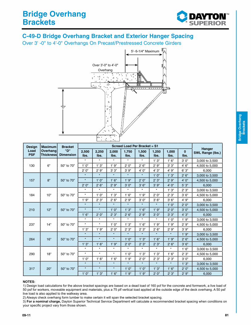
5'- 6-1/4" Maximum
"D"
Design Load PSF
Maximum Overhang Thickness
Bracket "D"
Dimension
Screed Load Per Bracket = S1Hanger
SWL Range (lbs.)2,500 lbs.
2,250 lbs.
2,000 lbs.
1,750 lbs.
1,500 lbs.
1,250 lbs.
1,000 lbs.
0 lbs.
130 6" 50" to 70"
* * * * * 1' 3" 1' 6" 3' 0" 3,000 to 3,500
1' 0" 1' 3" 1' 9" 2' 0" 2' 6" 2' 9" 3' 3" 4' 6" 4,500 to 5,000
2' 0" 2' 9" 3' 3" 3' 9" 4' 0" 4' 3" 4' 9" 6' 3" 6,000
157 8" 50" to 70"
* * * * * 1' 0" 1' 3" 2' 6" 3,000 to 3,500
* 1' 0" 1' 6" 1' 9" 2' 0" 2' 3" 2' 9" 4' 0" 4,500 to 5,000
2' 0" 2' 6" 2' 9" 3' 0" 3' 6" 3' 9" 4' 0" 5' 3" 6,000
184 10" 50" to 70"
* * * * * * 1' 3" 2' 3" 3,000 to 3,500
* 1' 0" 1' 3" 1' 6" 1' 9" 2' 0" 2' 3" 3' 6" 4,500 to 5,000
1' 9" 2' 3" 2' 6" 2' 9" 3' 0" 3' 6" 3' 6" 4' 9" 6,000
210 12" 50" to 70"
* * * * * * 1' 0" 2' 0" 3,000 to 3,500
* * 1' 0" 1' 3" 1' 6" 1' 9" 2' 0" 3' 0" 4,500 to 5,000
1' 6" 2' 0" 2' 3" 2' 6" 2' 9" 3' 0" 3' 3" 4' 3" 6,000
237 14" 50" to 70"
* * * * * * 1' 0" 1' 9" 3,000 to 3,500
* * 1' 0" 1' 3" 1' 6" 1' 9" 1' 9" 2' 9" 4,500 to 5,000
1' 3" 1' 9" 2' 0" 2' 3" 2' 3" 2' 6" 2' 9" 3' 9" 6,000
264 16" 50" to 70"
* * * * * * * 1' 9" 3,000 to 3,500
* * * 1' 0" 1' 3" 1' 6" 1' 9" 2' 6" 4,500 to 5,000
1' 3" 1' 6" 1' 9" 2' 0" 2' 3" 2' 3" 2' 6" 3' 6" 6,000
290 18" 50" to 70"
* * * * * * * 1' 6" 3,000 to 3,500
* * * 1' 0" 1' 3" 1' 3" 1' 6" 2' 3" 4,500 to 5,000
1' 0" 1' 6" 1' 6" 1' 9" 2' 0" 2' 3" 2' 3" 3' 0" 6,000
317 20" 50" to 70"
* * * * * * * 1' 3" 3,000 to 3,500
* * * 1' 0" 1' 0" 1' 3" 1' 6" 2' 0" 4,500 to 5,000
1' 0" 1' 3" 1' 6" 1' 9" 1' 9" 2' 0" 2' 3" 2' 9" 6,000
NOTES:1) Design load calculations for the above bracket spacings are based on a dead load of 160 pcf for the concrete and formwork, a live load of 50 psf for workers, moveable equipment and materials, plus a 75 plf vertical load applied at the outside edge of the deck overhang. A 50 psf live load is also applied to the walkway area. 2) Always check overhang form lumber to make certain it will span the selected bracket spacing.3) For a nominal charge, Dayton Superior Technical Service Department will calculate a recommended bracket spacing when conditions on yourspecificprojectvaryfromthoseshown.
Over 3'-0" to 4'-0"Overhang
C-49-D Bridge Overhang Bracket and Exterior Hanger SpacingOver 3' -0" to 4'-0" Overhangs On Precast/Prestressed Concrete Girders

82 09-11
®
Bridge Overhang Brackets
Brid
ge O
verhan
g
Brackets
C-49-S Bridge Overhang Bracket and Exterior Hanger SpacingOver 1’-0” to 2’-0” Overhangs On Steel Beams or Girders
3'- 10" Maximum
"D"
Over 1'-0" to 2'-0"Overhang
Block as Req'd
Design Load PSF
Maximum Overhang Thickness
Bracket "D"
Dimension
Screed Load Per Bracket = S1Hanger
SWL Range (lbs.)2,500 lbs.
2,250 lbs.
2,000 lbs.
1,750 lbs.
1,500 lbs.
1,250 lbs.
1,000 lbs.
0 lbs.
130 6" 14" to 28"
* * * 1' 0" 1' 6" 2' 3" 3' 0" 5' 9" 3,000 to 3,500
1' 9" 2' 6" 3' 3" 3' 9" 4' 6" 5' 3" 6' 0" 8' 0" 4,500 to 5,000
4' 9" 5' 6" 6' 0" 6' 9" 7' 6" 8' 0" 8' 0" 8' 0" 6,000
157 8" 14" to 28"
* * * * 1' 6" 2' 0" 2' 9" 5' 3" 3,000 to 3,500
1' 6" 2' 3" 2' 9" 3' 6" 4' 0" 4' 9" 5' 3" 7' 9" 4,500 to 5,000
4' 3" 4' 9" 5' 6" 6' 0" 6' 9" 7' 3" 8' 0" 8' 0" 6,000
184 10" 14" to 28"
* * * * 1' 3" 1' 9" 2' 6" 4' 9" 3,000 to 3,500
1' 6" 2' 0" 2' 6" 3' 0" 3' 9" 4' 3" 4' 9" 7' 0" 4,500 to 5,000
3' 9" 4' 6" 5' 0" 5' 6" 6' 0" 6' 9" 7' 3" 8' 0" 6,000
210 12" 14" to 28"
* * * * 1' 3" 1' 9" 2' 3" 4' 3" 3,000 to 3,500
1' 3" 1' 9" 2' 3" 2' 9" 3' 3" 4' 0" 4' 6" 6' 6" 4,500 to 5,000
3' 6" 4' 0" 4' 6" 5' 0" 5' 6" 6' 0" 6' 6" 8' 0" 6,000
237 14" 14" to 28"
* * * * 1' 0" 1' 6" 2' 0" 4' 0" 3,000 to 3,500
1' 3" 1' 9" 2' 3" 2' 6" 3' 0" 3' 6" 4' 0" 6' 0" 4,500 to 5,000
3' 3" 3' 9" 4' 3" 4' 9" 5' 3" 5' 6" 6' 0" 8' 0" 6,000
264 16" 14" to 28"
* * * * 1' 0" 1' 6" 1' 9" 3' 9" 3,000 to 3,500
1' 0" 1' 6" 2' 0" 2' 6" 2' 9" 3' 3" 3' 9" 5' 6" 4,500 to 5,000
3' 0" 3' 6" 3' 9" 4' 3" 4' 9" 5' 3" 5' 9" 7' 6" 6,000
290 18" 14" to 28"
* * * * 1' 0" 1' 3" 1' 9" 3' 6" 3,000 to 3,500
1' 0" 1' 6" 1' 9" 2' 3" 2' 9" 3' 0" 3' 6 5' 3" 4,500 to 5,000
2' 9" 3' 3" 3' 6" 4' 0" 4' 6" 4' 9" 5' 3" 7' 0" 6,000
317 20" 14" to 28"
* * * * * 1' 3" 1' 6" 3' 3" 3,000 to 3,500
1' 0" 1' 3" 1' 9" 2' 0" 2' 6" 3' 0" 3' 3" 4' 9" 4,500 to 5,000
2' 6" 3' 0" 3' 3" 3' 9" 4' 3" 4' 6" 5' 0" 6' 6" 6,000
NOTES:1) Design load calculations for the above bracket spacings are based on a dead load of 160 pcf for the concrete and formwork, a live load of 50 psf for workers, moveable equipment and materials, plus a 75 plf vertical load applied at the outside edge of the deck overhang. A 50 psf live load is also applied to the walkway area. 2) Always check overhang form lumber to make certain it will span the selected bracket spacing.3) For a nominal charge, Dayton Superior Technical Service Department will calculate a recommended bracket spacing when conditions on yourspecificprojectvaryfromthoseshown.
8309-11
®
Bridge Overhang Brackets
Bri
dg
e O
verh
ang
B
rack
ets
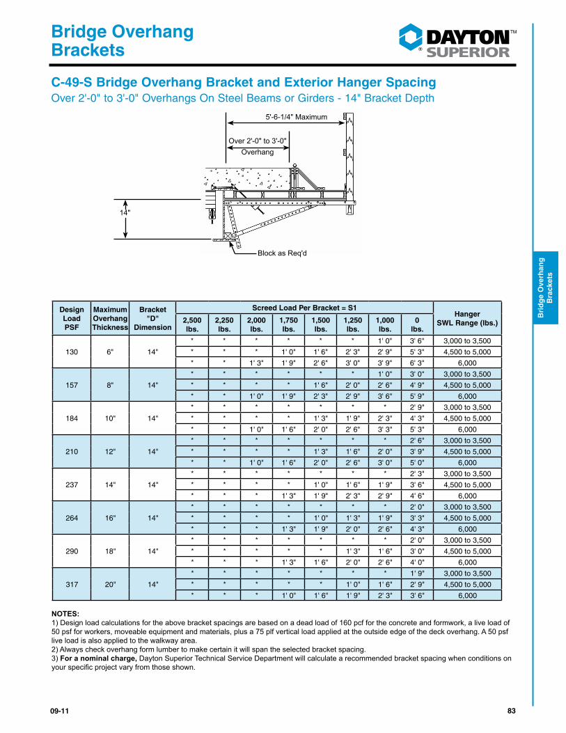
C-49-S Bridge Overhang Bracket and Exterior Hanger SpacingOver 2'-0" to 3'-0" Overhangs On Steel Beams or Girders - 14" Bracket Depth
5'-6-1/4" Maximum
14"
Over 2'-0" to 3'-0"Overhang
Block as Req'd
Design Load PSF
Maximum Overhang Thickness
Bracket "D"
Dimension
Screed Load Per Bracket = S1Hanger
SWL Range (lbs.)2,500 lbs.
2,250 lbs.
2,000 lbs.
1,750 lbs.
1,500 lbs.
1,250 lbs.
1,000 lbs.
0 lbs.
130 6" 14"
* * * * * * 1' 0" 3' 6" 3,000 to 3,500
* * * 1' 0" 1' 6" 2' 3" 2' 9" 5' 3" 4,500 to 5,000
* * 1' 3" 1' 9" 2' 6" 3' 0" 3' 9" 6' 3" 6,000
157 8" 14"
* * * * * * 1' 0" 3' 0" 3,000 to 3,500
* * * * 1' 6" 2' 0" 2' 6" 4' 9" 4,500 to 5,000
* * 1' 0" 1' 9" 2' 3" 2' 9" 3' 6" 5' 9" 6,000
184 10" 14"
* * * * * * * 2' 9" 3,000 to 3,500
* * * * 1' 3" 1' 9" 2' 3" 4' 3" 4,500 to 5,000
* * 1' 0" 1' 6" 2' 0" 2' 6" 3' 3" 5' 3" 6,000
210 12" 14"
* * * * * * * 2' 6" 3,000 to 3,500
* * * * 1' 3" 1' 6" 2' 0" 3' 9" 4,500 to 5,000
* * 1' 0" 1' 6" 2' 0" 2' 6" 3' 0" 5' 0" 6,000
237 14" 14"
* * * * * * * 2' 3" 3,000 to 3,500
* * * * 1' 0" 1' 6" 1' 9" 3' 6" 4,500 to 5,000
* * * 1' 3" 1' 9" 2' 3" 2' 9" 4' 6" 6,000
264 16" 14"
* * * * * * * 2' 0" 3,000 to 3,500
* * * * 1' 0" 1' 3" 1' 9" 3' 3" 4,500 to 5,000
* * * 1' 3" 1' 9" 2' 0" 2' 6" 4' 3" 6,000
290 18" 14"
* * * * * * * 2' 0" 3,000 to 3,500
* * * * * 1' 3" 1' 6" 3' 0" 4,500 to 5,000
* * * 1' 3" 1' 6" 2' 0" 2' 6" 4' 0" 6,000
317 20" 14"
* * * * * * * 1' 9" 3,000 to 3,500
* * * * * 1' 0" 1' 6" 2' 9" 4,500 to 5,000
* * * 1' 0" 1' 6" 1' 9" 2' 3" 3' 6" 6,000
NOTES:1) Design load calculations for the above bracket spacings are based on a dead load of 160 pcf for the concrete and formwork, a live load of 50 psf for workers, moveable equipment and materials, plus a 75 plf vertical load applied at the outside edge of the deck overhang. A 50 psf live load is also applied to the walkway area. 2) Always check overhang form lumber to make certain it will span the selected bracket spacing.3) For a nominal charge, Dayton Superior Technical Service Department will calculate a recommended bracket spacing when conditions on yourspecificprojectvaryfromthoseshown.
84 09-11
®
Bridge Overhang Brackets
Brid
ge O
verhan
g
Brackets
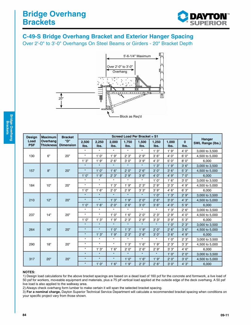
5'-6-1/4" Maximum
20"
Over 2'-0" to 3'-0"Overhang
Block as Req'd
Design Load PSF
Maximum Overhang Thickness
Bracket "D"
Dimension
Screed Load Per Bracket = S1Hanger
SWL Range (lbs.)2,500 lbs.
2,250 lbs.
2,000 lbs.
1,750 lbs.
1,500 lbs.
1,250 lbs.
1,000 lbs.
0 lbs.
130 6" 20"
* * * * * 1' 3" 1' 9" 4' 0" 3,000 to 3,500
* 1' 0" 1' 9" 2' 3" 2' 9" 3' 6" 4' 0" 6' 0" 4,500 to 5,000
1' 3" 1' 9" 2' 6" 3' 0" 3' 9" 4' 3" 5' 0" 8' 0" 6,000
157 8" 20"
* * * * * 1' 3" 1' 9" 3' 6" 3,000 to 3,500
* 1' 0" 1' 6" 2' 0" 2' 6" 3' 0" 3' 6" 5' 3" 4,500 to 5,000
1' 0" 1' 9" 2' 3" 2' 9" 3' 6" 4' 0" 4' 9" 7' 0" 6,000
184 10" 20"
* * * * * 1' 0" 1' 6" 3' 0" 3,000 to 3,500
* * 1' 3" 1' 9" 2' 3" 2' 9" 3' 3" 4' 9" 4,500 to 5,000
1' 0" 1' 6" 2' 0" 2' 9" 3' 3" 3' 9" 4' 6" 6' 3" 6,000
210 12" 20"
* * * * * 1' 0" 1' 3" 2' 9" 3,000 to 3,500
* * 1' 3" 1' 9" 2' 0" 2' 6" 3' 0" 4' 3" 4,500 to 5,000
1' 0" 1' 6" 2' 0" 2' 6" 3' 0" 3' 6" 4' 0" 5' 9" 6,000
237 14" 20"
* * * * * * 1' 3" 2' 6" 3,000 to 3,500
* * 1' 0" 1' 6" 2' 0" 2' 3" 2' 9" 4' 0" 4,500 to 5,000
1' 0" 1' 3" 1' 9" 2' 3" 2' 9" 3' 3" 3' 9" 5' 3" 6,000
264 16" 20"
* * * * * * 1' 0" 2' 3" 3,000 to 3,500
* * 1' 0" 1' 3" 1' 9" 2' 0" 2' 6" 3' 6" 4,500 to 5,000
* 1' 3" 1' 9" 2' 3" 2' 6" 3' 0" 3' 6" 4' 9" 6,000
290 18" 20"
* * * * * * 1' 0" 2' 3" 3,000 to 3,500
* * * 1' 3" 1' 6" 1' 9" 2' 3" 3' 3" 4,500 to 5,000
* 1' 3" 1' 6" 2' 0" 2' 6" 2' 9" 3' 3" 4' 6" 6,000
317 20" 20"
* * * * * * 1' 0" 2' 0" 3,000 to 3,500
* * * 1' 0" 1' 6" 1' 9" 2' 0" 3' 0" 4,500 to 5,000
* 1' 0" 1' 6" 1' 9" 2' 3" 2' 6" 3' 0" 4' 3" 6,000
NOTES:1) Design load calculations for the above bracket spacings are based on a dead load of 160 pcf for the concrete and formwork, a live load of 50 psf for workers, moveable equipment and materials, plus a 75 plf vertical load applied at the outside edge of the deck overhang. A 50 psf live load is also applied to the walkway area. 2) Always check overhang form lumber to make certain it will span the selected bracket spacing.3) For a nominal charge, Dayton Superior Technical Service Department will calculate a recommended bracket spacing when conditions on yourspecificprojectvaryfromthoseshown.
C-49-S Bridge Overhang Bracket and Exterior Hanger SpacingOver 2'-0" to 3'-0" Overhangs On Steel Beams or Girders - 20" Bracket Depth
8509-11
®
Bridge Overhang Brackets
Bri
dg
e O
verh
ang
B
rack
ets
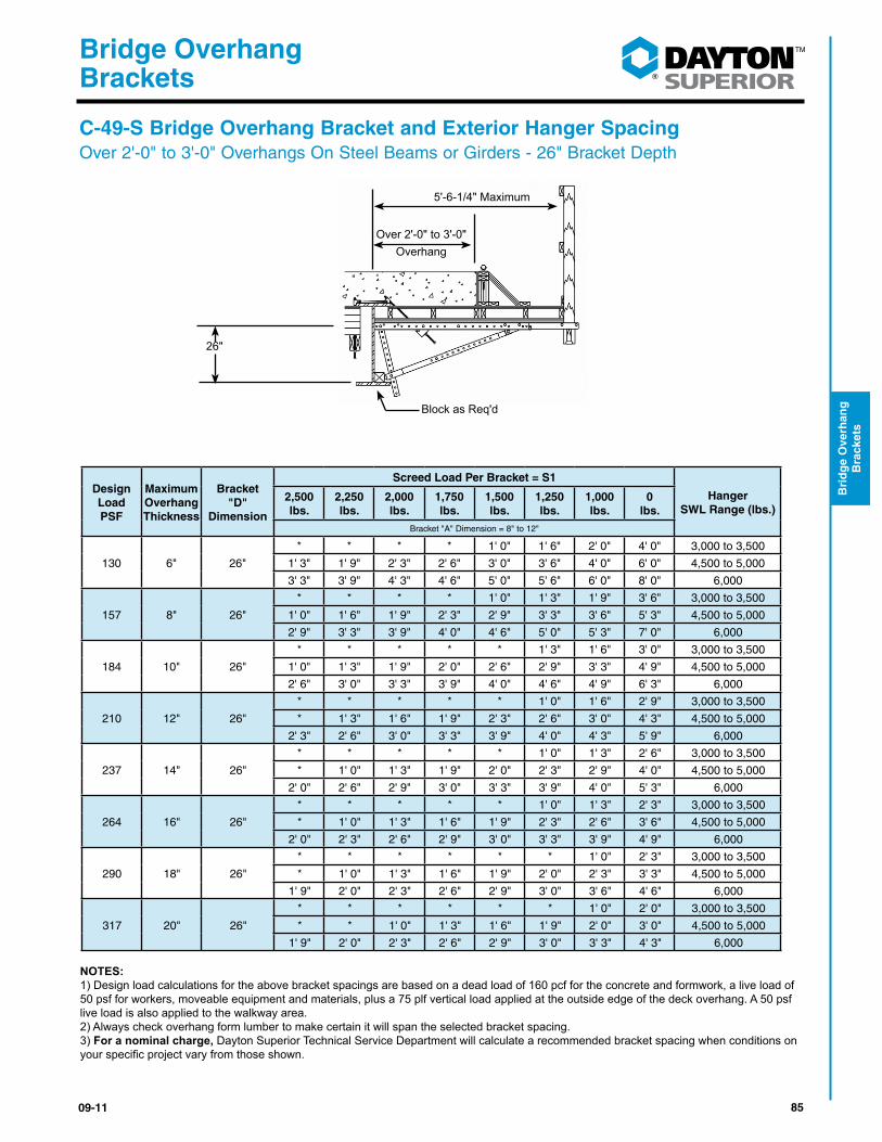
5'-6-1/4" Maximum
26"
Over 2'-0" to 3'-0"Overhang
Block as Req'd
Design Load PSF
Maximum Overhang Thickness
Bracket "D"
Dimension
Screed Load Per Bracket = S1
Hanger SWL Range (lbs.)
2,500 lbs.
2,250 lbs.
2,000 lbs.
1,750 lbs.
1,500 lbs.
1,250 lbs.
1,000 lbs.
0 lbs.
Bracket "A" Dimension = 8" to 12"
130 6" 26"
* * * * 1' 0" 1' 6" 2' 0" 4' 0" 3,000 to 3,500
1' 3" 1' 9" 2' 3" 2' 6" 3' 0" 3' 6" 4' 0" 6' 0" 4,500 to 5,000
3' 3" 3' 9" 4' 3" 4' 6" 5' 0" 5' 6" 6' 0" 8' 0" 6,000
157 8" 26"
* * * * 1' 0" 1' 3" 1' 9" 3' 6" 3,000 to 3,500
1' 0" 1' 6" 1' 9" 2' 3" 2' 9" 3' 3" 3' 6" 5' 3" 4,500 to 5,000
2' 9" 3' 3" 3' 9" 4' 0" 4' 6" 5' 0" 5' 3" 7' 0" 6,000
184 10" 26"
* * * * * 1' 3" 1' 6" 3' 0" 3,000 to 3,500
1' 0" 1' 3" 1' 9" 2' 0" 2' 6" 2' 9" 3' 3" 4' 9" 4,500 to 5,000
2' 6" 3' 0" 3' 3" 3' 9" 4' 0" 4' 6" 4' 9" 6' 3" 6,000
210 12" 26"
* * * * * 1' 0" 1' 6" 2' 9" 3,000 to 3,500
* 1' 3" 1' 6" 1' 9" 2' 3" 2' 6" 3' 0" 4' 3" 4,500 to 5,000
2' 3" 2' 6" 3' 0" 3' 3" 3' 9" 4' 0" 4' 3" 5' 9" 6,000
237 14" 26"
* * * * * 1' 0" 1' 3" 2' 6" 3,000 to 3,500
* 1' 0" 1' 3" 1' 9" 2' 0" 2' 3" 2' 9" 4' 0" 4,500 to 5,000
2' 0" 2' 6" 2' 9" 3' 0" 3' 3" 3' 9" 4' 0" 5' 3" 6,000
264 16" 26"
* * * * * 1' 0" 1' 3" 2' 3" 3,000 to 3,500
* 1' 0" 1' 3" 1' 6" 1' 9" 2' 3" 2' 6" 3' 6" 4,500 to 5,000
2' 0" 2' 3" 2' 6" 2' 9" 3' 0" 3' 3" 3' 9" 4' 9" 6,000
290 18" 26"
* * * * * * 1' 0" 2' 3" 3,000 to 3,500
* 1' 0" 1' 3" 1' 6" 1' 9" 2' 0" 2' 3" 3' 3" 4,500 to 5,000
1' 9" 2' 0" 2' 3" 2' 6" 2' 9" 3' 0" 3' 6" 4' 6" 6,000
317 20" 26"
* * * * * * 1' 0" 2' 0" 3,000 to 3,500
* * 1' 0" 1' 3" 1' 6" 1' 9" 2' 0" 3' 0" 4,500 to 5,000
1' 9" 2' 0" 2' 3" 2' 6" 2' 9" 3' 0" 3' 3" 4' 3" 6,000
NOTES:1) Design load calculations for the above bracket spacings are based on a dead load of 160 pcf for the concrete and formwork, a live load of 50 psf for workers, moveable equipment and materials, plus a 75 plf vertical load applied at the outside edge of the deck overhang. A 50 psf live load is also applied to the walkway area. 2) Always check overhang form lumber to make certain it will span the selected bracket spacing.3) For a nominal charge, Dayton Superior Technical Service Department will calculate a recommended bracket spacing when conditions on yourspecificprojectvaryfromthoseshown.
C-49-S Bridge Overhang Bracket and Exterior Hanger SpacingOver 2'-0" to 3'-0" Overhangs On Steel Beams or Girders - 26" Bracket Depth

86 09-11
®
Bridge Overhang Brackets
Brid
ge O
verhan
g
Brackets
C-49-S Bridge Overhang Bracket and Exterior Hanger SpacingOver 3'-0" to 4'-0" Overhangs On Steel Beams or Girders - 14" Bracket Depth
5'-6-1/4" Maximum
14"
Over 3'-0" to 4'-0"Overhang
Block as Req'd
Design Load PSF
Maximum Overhang Thickness
Bracket "D"
Dimension
Screed Load Per Bracket = S1Hanger
SWL Range (lbs.)2,500 lbs.
2,250 lbs.
2,000 lbs.
1,750 lbs.
1,500 lbs.
1,250 lbs.
1,000 lbs.
0 lbs.
130 6" 14"
* * * * * * * 2' 9" 3,000 to 3,500
* * * * * * 1' 6" 4' 0" 4,500 to 5,000
* * * * * 1' 6" 2' 3" 4' 9" 6,000
157 8" 14"
* * * * * * * 2' 3" 3,000 to 3,500
* * * * * * 1' 3" 3' 6" 4,500 to 5,000
* * * * * 1' 3" 2' 0" 4' 3" 6,000
184 10" 14"
* * * * * * * 2' 0" 3,000 to 3,500
* * * * * * 1' 3" 3' 3" 4,500 to 5,000
* * * * * 1' 3" 1' 9" 3' 9" 6,000
210 12" 14"
* * * * * * * 1' 9" 3,000 to 3,500
* * * * * * 1' 0" 2' 9" 4,500 to 5,000
* * * * * 1' 0" 1' 6" 3' 6" 6,000
237 14" 14"
* * * * * * * 1' 6" 3,000 to 3,500
* * * * * * 1' 0" 2' 6" 4,500 to 5,000
* * * * * 1' 0" 1' 6" 3' 3" 6,000
264 16" 14"
* * * * * * * 1' 6" 3,000 to 3,500
* * * * * * * 2' 3" 4,500 to 5,000
* * * * * * 1' 3" 3' 0" 6,000
290 18" 14"
* * * * * * * 1' 3" 3,000 to 3,500
* * * * * * * 1' 9" 4,500 to 5,000
* * * * * * 1' 3" 2' 9" 6,000
317 20" 14"
* * * * * * * 1' 3" 3,000 to 3,500
* * * * * * * 1' 9" 4,500 to 5,000
* * * * * * 1' 0" 2' 6" 6,000
NOTES:1) Design load calculations for the above bracket spacings are based on a dead load of 160 pcf for the concrete and formwork, a live load of 50 psf for workers, moveable equipment and materials, plus a 75 plf vertical load applied at the outside edge of the deck overhang. A 50 psf live load is also applied to the walkway area. 2) Always check overhang form lumber to make certain it will span the selected bracket spacing.3) For a nominal charge, Dayton Superior Technical Service Department will calculate a recommended bracket spacing when conditions on yourspecificprojectvaryfromthoseshown.
8709-11
®
Bridge Overhang Brackets
Bri
dg
e O
verh
ang
B
rack
ets
Design Load PSF
Maximum Overhang Thickness
Bracket "D"
Dimension
Screed Load Per Bracket = S1Hanger
SWL Range (lbs.)2,500 lbs.
2,250 lbs.
2,000 lbs.
1,750 lbs.
1,500 lbs.
1,250 lbs.
1,000 lbs.
0 lbs.
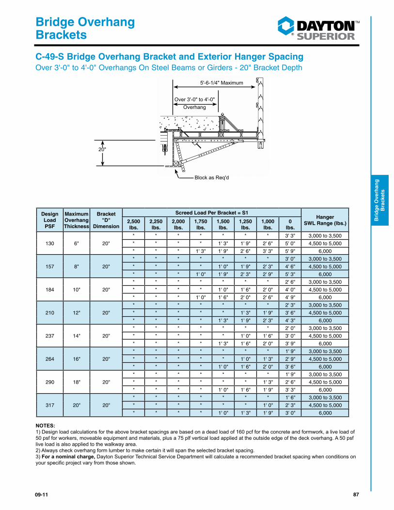
130 6" 20"
* * * * * * * 3' 3" 3,000 to 3,500
* * * * 1' 3" 1' 9" 2' 6" 5' 0" 4,500 to 5,000
* * * 1' 3" 1' 9" 2' 6" 3' 3" 5' 9" 6,000
157 8" 20"
* * * * * * * 3' 0" 3,000 to 3,500
* * * * 1' 0" 1' 9" 2' 3" 4' 6" 4,500 to 5,000
* * * 1' 0" 1' 9" 2' 3" 2' 9" 5' 3" 6,000
184 10" 20"
* * * * * * * 2' 6" 3,000 to 3,500
* * * * 1' 0" 1' 6" 2' 0" 4' 0" 4,500 to 5,000
* * * 1' 0" 1' 6" 2' 0" 2' 6" 4' 9" 6,000
210 12" 20"
* * * * * * * 2' 3" 3,000 to 3,500
* * * * * 1' 3" 1' 9" 3' 6" 4,500 to 5,000
* * * * 1' 3" 1' 9" 2' 3" 4' 3" 6,000
237 14" 20"
* * * * * * * 2' 0" 3,000 to 3,500
* * * * * 1' 0" 1' 6" 3' 0" 4,500 to 5,000
* * * * 1' 3" 1' 6" 2' 0" 3' 9" 6,000
264 16" 20"
* * * * * * * 1' 9" 3,000 to 3,500
* * * * * 1' 0" 1' 3" 2' 9" 4,500 to 5,000
* * * * 1' 0" 1' 6" 2' 0" 3' 6" 6,000
290 18" 20"
* * * * * * * 1' 9" 3,000 to 3,500
* * * * * * 1' 3" 2' 6" 4,500 to 5,000
* * * * 1' 0" 1' 6" 1' 9" 3' 3" 6,000
317 20" 20"
* * * * * * * 1' 6" 3,000 to 3,500
* * * * * * 1' 0" 2' 3" 4,500 to 5,000
* * * * 1' 0" 1' 3" 1' 9" 3' 0" 6,000
NOTES:1) Design load calculations for the above bracket spacings are based on a dead load of 160 pcf for the concrete and formwork, a live load of 50 psf for workers, moveable equipment and materials, plus a 75 plf vertical load applied at the outside edge of the deck overhang. A 50 psf live load is also applied to the walkway area. 2) Always check overhang form lumber to make certain it will span the selected bracket spacing.3) For a nominal charge, Dayton Superior Technical Service Department will calculate a recommended bracket spacing when conditions on yourspecificprojectvaryfromthoseshown.
C-49-S Bridge Overhang Bracket and Exterior Hanger SpacingOver 3'-0" to 4'-0" Overhangs On Steel Beams or Girders - 20" Bracket Depth
5'-6-1/4" Maximum
20"
Over 3'-0" to 4'-0"Overhang
Block as Req'd

88 09-11
®
Bridge Overhang Brackets
Brid
ge O
verhan
g
Brackets
Design Load PSF
Maximum Overhang Thickness
Bracket "D"
Dimension
Screed Load Per Bracket = S1Hanger
SWL Range (lbs.)2,500 lbs.
2,250 lbs.
2,000 lbs.
1,750 lbs.
1,500 lbs.
1,250 lbs.
1,000 lbs.
0 lbs.
130 6" 26"
* * * * * * 1' 6" 3' 6" 3,000 to 3,500 * * 1' 0" 1' 9" 2' 3" 3' 0" 3' 6" 5' 3" 4,500 to 5,000 * * 1' 6" 2' 0" 2' 9" 3' 6" 4' 0" 7' 0" 6,000
157 8" 26"
* * * * * * 1' 3" 3' 0" 3,000 to 3,500 * * * 1' 6" 2' 0" 2' 6" 3' 0" 4' 6" 4,500 to 5,000 * * 1' 3" 1' 9" 2' 6" 3' 0" 3' 9" 6' 0" 6,000
184 10" 26"
* * * * * * 1' 0" 2' 6" 3,000 to 3,500 * * * 1' 3" 1' 9" 2' 3" 2' 9" 4' 0" 4,500 to 5,000 * * 1' 0" 1' 9" 2' 3" 2' 9" 3' 3" 5' 3" 6,000
210 12" 26"
* * * * * * 1' 0" 2' 3" 3,000 to 3,500 * * * 1' 0" 1' 6" 2' 0" 2' 3" 3' 6" 4,500 to 5,000 * * 1' 0" 1' 6" 2' 0" 2' 6" 3' 0" 4' 9" 6,000
237 14" 26"
* * * * * * * 2' 0" 3,000 to 3,500 * * * 1' 0" 1' 3" 1' 9" 2' 0" 3' 3" 4,500 to 5,000 * * 1' 0" 1' 3" 1' 9" 2' 3" 2' 9" 4' 3" 6,000
264 16" 26"
* * * * * * * 1' 9" 3,000 to 3,500 * * * * 1' 3" 1' 6" 2' 0" 2' 9" 4,500 to 5,000 * * * 1' 3" 1' 9" 2' 0" 2' 6" 3' 9" 6,000
290 18" 26"
* * * * * * * 1' 9" 3,000 to 3,500 * * * * 1' 0" 1' 6" 1' 9" 2' 6" 4,500 to 5,000 * * * 1' 3" 1' 6" 2' 0" 2' 3" 3' 6" 6,000
317 20" 26"
* * * * * * * 1' 6" 3,000 to 3,500 * * * * 1' 0" 1' 3" 1' 6" 2' 6" 4,500 to 5,000 * * * 1' 0" 1' 6" 1' 9" 2' 0" 3' 3" 6,000
NOTES:1) Design load calculations for the above bracket spacings are based on a dead load of 160 pcf for the concrete and formwork, a live load of 50 psf for workers, moveable equipment and materials, plus a 75 plf vertical load applied at the outside edge of the deck overhang. A 50 psf live load is also applied to the walkway area. 2) Always check overhang form lumber to make certain it will span the selected bracket spacing.3) For a nominal charge, Dayton Superior Technical Service Department will calculate a recommended bracket spacing when condi-tionsonyourspecificprojectvaryfromthoseshown.
C-49-S Bridge Overhang Bracket and Exterior Hanger SpacingOver 3'-0" to 4'-0" Overhangs On Steel Beams or Girders - 26" Bracket Depth
5'-6-1/4" Maximum
26"
Over 3'-0" to 4'-0"Overhang
Block as Req'd

8909-11
®
Bridge Overhang Brackets
Bri
dg
e O
verh
ang
B
rack
ets
Design Load PSF
Slab Thickness
Bracket "D"
Dimension
Screed Load Per Bracket = S1
Hanger SWL2,500
lbs.2,250 lbs.
2,000 lbs.
1,750 lbs.
1,500 lbs.
1,250 lbs.
1,000 lbs.
0 lbs.
130 6" 14" * * * * * 1'-1" 1'-9" 4'-7" 3,000 to 3,500 * * * * * 2'-2" 3'-4" 6'-11" 4,500 to 5,000 * * * * * 2'-2" 3'-4" 8'-0" 6,000
130 6" 20"* * * * 1'-4" 1'-11" 2'-6" 4'-9" 3,000 to 3,500 * * 2'-0" 3'-2" 3'-9" 4'-4" 4'-10" 7'-1" 4,500 to 5,000 * * 2'-0" 3'-3" 4'-5" 5'-8" 6'-10" 8'-0" 6,000
130 6" 26"* * * * 1'-4" 1'-11" 2'-6" 4'-9" 3,000 to 3,500
1'-6" 2'-1" 2'-7" 3'-2" 3'-9" 4'-4" 4'-10" 7'-1" 4,500 to 5,000 2'-9" 4'-0" 5'-0" 5'-7" 6'-1" 6'-8" 7'-3" 8'-0" 6,000
157 8" 14"* * * * * * 1'-7" 4'-2" 3,000 to 3,500 * * * * * 2'-0" 3'-1" 6'-4" 4,500 to 5,000 * * * * * 2'-0" 3'-1" 7'-7" 6,000
157 8" 20"* * * * 1'-2" 1'-8" 2'-2" 4'-3" 3,000 to 3,500 * * 1'-11" 2'-10" 3'-4" 3'-10" 4'-4" 6'-4" 4,500 to 5,000 * * 1'-11" 3'-0" 4'-2" 5'-4" 6'-5" 8'-0" 6,000
157 8" 26"* * * * 1'-2" 1'-8" 2'-2" 4'-3" 3,000 to 3,500
1'-4" 1'-10" 2'-4" 2'-10" 3'-4" 3'-10" 4'-4" 6'-4" 4,500 to 5,000 2'-7" 3'-9" 4'-5" 4'-11" 5'-5" 5'-11" 6'-6" 8'-0" 6,000
183 10" 14"* * * * * * 1'-5" 3'-9" 3,000 to 3,500 * * * * * 1'-10" 2'-11" 5'-8" 4,500 to 5,000 * * * * * 1'-10" 2'-11" 7'-1" 6,000
183 10" 20"* * * * 1'-1" 1'-6" 2'-0" 3'-10" 3,000 to 3,500 * * 1'-9" 2'-7" 3'-0" 3'-5" 3'-11" 5'-9" 4,500 to 5,000 * * 1'-9" 2'-10" 3'-10" 4'-11" 5'-10" 7'-8" 6,000
183 10" 26"* * * * 1'-1" 1'-6" 2'-0" 3'-10" 3,000 to 3,500
1'-2" 1'-8" 2'-1" 2'-7" 3'-0" 3'-5" 3'-11" 5'-9" 4,500 to 5,000 2'-5" 3'-6" 4'-0" 4'-6" 4'-11" 5'-5" 5'-10" 7'-8" 6,000
210 12" 14"* * * * * * 1'-4" 3'-5" 3,000 to 3,500 * * * * * 1'-9" 2'-8" 5'-2" 4,500 to 5,000 * * * * * 1'-9" 2'-8" 6'-6" 6,000
210 12" 20"* * * * 1'-0" 1'-5" 1'-10" 3'-6" 3,000 to 3,500 * * 1'-8" 2'-4" 2'-9" 3'-2" 3'-7" 5'-3" 4,500 to 5,000 * * 1'-8" 2'-7" 3'-7" 4'-7" 5'-4" 7'-0" 6,000
210 12" 26"* * * * 1'-0" 1'-5" 1'-10" 3'-6" 3,000 to 3,500
1'-1" 1'-6" 1'-11" 2'-4" 2'-9" 3'-2" 3'-7" 5'-3" 4,500 to 5,000 2'-3" 3'-3" 3'-8" 4'-1" 4'-6" 4'-11" 5'-4" 7'-0" 6,000
237 14" 14"* * * * * * 1'-2" 3'-1" 3,000 to 3,500 * * * * * 1'-7" 2'-6" 4'-8" 4,500 to 5,000 * * * * * 1'-7" 2'-6" 5'-11" 6,000
237 14" 20"* * * * * 1'-3" 1'-8" 3'-2" 3,000 to 3,500 * * 1'-6" 2'-2" 2'-6" 2'-11" 3'-3" 4'-9" 4,500 to 5,000 * * 1'-6" 2'-5" 3'-4" 4'-2" 4'-11" 6'-5" 6,000
237 14" 26"* * * * * 1'-3" 1'-8" 3'-2" 3,000 to 3,500
1'-0" 1'-4" 1'-9" 2'-2" 2'-6" 2'-11" 3'-3" 4'-9" 4,500 to 5,000 2'-1" 3'-0" 3'-4" 3'-9" 4'-1" 4'-6" 4'-11" 6'-5" 6,000
263 16" 14"* * * * * * 1'-1" 2'-9" 3,000 to 3,500 * * * * * 1'-5" 2'-3" 4'-2" 4,500 to 5,000 * * * * * 1'-5" 2'-3" 5'-4" 6,000
263 16" 20"* * * * * 1'-2" 1'-6" 2'-11" 3,000 to 3,500 * * 1'-4" 2'-0" 2'-4" 2'-8" 3'-0" 4'-5" 4,500 to 5,000 * * 1'-4" 2'-2" 3'-0" 3'-10" 4'-6" 5'-11" 6,000
263 16" 24"* * * * * 1'-2" 1'-6" 2'-11" 3,000 to 3,500 * 1'-3" 1'-7" 2'-0" 2'-4" 2'-8" 3'-0" 4'-5" 4,500 to 5,000
1'-11" 2'-8" 3'-1" 3'-5" 3'-10" 4'-2" 4'-6" 5'-11" 6,000
290 18" 14"* * * * * * * 2'-6" 3,000 to 3,500 * * * * * 1'-4" 2'-1" 3'-9" 4,500 to 5,000 * * * * * 1'-4" 2'-1" 4'-10" 6,000
290 18" 20"* * * * * 1'-1" 1'-5" 2'-9" 3,000 to 3,500 * * 1'-3" 1'-10" 2'-2" 2'-6" 2'-10" 4'-1" 4,500 to 5,000 * * 1'-3" 2'-0" 2'-9" 3'-6" 4'-2" 5'-6" 6,000
290 18" 26"* * * * * 1'-1" 1'-5" 2'-9" 3,000 to 3,500 * 1'-2" 1'-6" 1'-10" 2'-2" 2'-6" 2'-10" 4'-1" 4,500 to 5,000
1'-9" 2'-6" 2'-11" 3'-3" 3'-6" 3'-10" 4'-2" 5'-6" 6,000
317 20" 14"* * * * * * * 2'-3" 3,000 to 3,500 * * * * * 1'-2" 1'-10" 3'-5" 4,500 to 5,000 * * * * * 1'-2" 1'-10" 4'-4" 6,000
317 20" 20"* * * * * 1'-0" 1'-4" 2'-7" 3,000 to 3,500 * * 1'-2" 1'-8" 2'-0" 2'-4" 2'-7" 3'-10" 4,500 to 5,000 * * 1'-2" 1'-10" 2'-6" 3'-2" 3'-10" 5'-2" 6,000
317 20" 26"* * * * * 1'-0" 1'-4" 2'-7" 3,000 to 3,500 * 1'-1" 1'-5" 1'-8" 2'-0" 2'-4" 2'-7" 3'-10" 4,500 to 5,000
1'-7" 2'-3" 2'-8" 3'-0" 3'-4" 3'-7" 3'-11" 5'-2" 6,000
NOTES:1) Design load calculations for the above bracket spacings are based on a dead load of 160 pcf for the concrete and formwork, a live load of 50 psf for workers, moveable equipment and materials, plus a 75 plf vertical load applied at the outside edge of the deck overhang. A 50 psf live load is also applied to the walkway area. 2) Always check overhang form lumber to make certain it will span the selected bracket spacing.3) For a nominal charge, Dayton Superior Technical Service Department will calculate a recommended bracket spacing when conditions on your spe-cificprojectvaryfromthoseshown.
C-49-S Bridge Overhang Bracket and Exterior Hanger SpacingOver 1’-0” To 2’-0” Overhangs On Precast/Prestressed Concrete Girders
C-49-S Bracket With Hanger & Concrete Beam Concrete Box BeamOver 1'-0" to 2'-0" Overhang Forming 3/4" ply., 3 1/2" joist & 2x nailer on flat
D
Over 1'-0" to 2'-0"
Overhang
3'-10" MAXIMUM

90 09-11
®
Bridge Overhang Brackets
Brid
ge O
verhan
g
Brackets
C-49-S Bridge Overhang Bracket and Exterior Hanger SpacingOver 2'-0" - 3'-0" Overhangs On Precast/Prestressed Concrete Girders
C-49-S Bracket With Hanger & Concrete Beam Concrete Box BeamOverhang 2'-0" to 3'-0" Overhang Forming 3/4" ply., 3 1/2" joist & 2x nailer on flat
Over 2'-0" to 3'-0"Overhang
5'-6 1/4" MAXIMUM
Design Load PSF
Slab Thickness
Bracket "D"
Dimension
Screed Load Per Bracket = S1
Hanger SWL2,500
lbs.2,250 lbs.
2,000 lbs.
1,750 lbs.
1,500 lbs.
1,250 lbs.
1,000 lbs.
0 lbs.
130 6" 14" * * * * * * * 3'-5" 3,000 to 3,500* * * * * * * 5'-2" 4,500 to 5,000 * * * * * * * 5'-3" 6,000
130 6" 20"* * * * * * 1'-4" 4'-0" 3,000 to 3,500 * * * * * 2'-0" 3'-2" 6'-0" 4,500 to 5,000 * * * * * 2'-0" 3'-2" 7'-11" 6,000
130 6" 26"* * * * * 1'-7" 2'-1" 4'-0" 3,000 to 3,500 * * * 1'-9" 3'-0" 3'-8" 4'-1" 6'-0" 4,500 to 5,000 * * * 1'-9" 3'-0" 4'-2" 5'-4" 8'-0" 6,000
157 8" 14"* * * * * * * 3'-0" 3,000 to 3,500 * * * * * * * 4'-6" 4,500 to 5,000 * * * * * * * 4'-8" 6,000
157 8" 20"* * * * * * 1'-2" 3'-6" 3,000 to 3,500 * * * * * 1'-9" 2'-10" 5'-3" 4,500 to 5,000 * * * * * 1'-9" 2'-10" 7'-0" 6,000
157 8" 26"* * * * * 1'-4" 1'-10" 3'-6" 3,000 to 3,500 * * * 1'-7" 2'-8" 3'-2" 3'-7" 5'-3" 4,500 to 5,000 * * * 1'-7" 2'-8" 3'-9" 4'-9" 7'-0" 6,000
183 10" 14"* * * * * * * 2'-8" 3,000 to 3,500 * * * * * * * 4'-0" 4,500 to 5,000 * * * * * * * 4'-2" 6,000
183 10" 20"* * * * * * 1'-0" 3'-1" 3,000 to 3,500 * * * * * 1'-7" 2'-7" 4'-7" 4,500 to 5,000 * * * * * 1'-7" 2'-7" 6'-2" 6,000
183 10" 26"* * * * * 1'-2" 1'-7" 3'-1" 3,000 to 3,500 * * * 1'-5" 2'-5" 2'-9" 3'-2" 4'-7" 4,500 to 5,000 * * * 1'-5" 2'-5" 3'-4" 4'-4" 6'-2" 6,000
210 12" 14"* * * * * * * 2'-4" 3,000 to 3,500 * * * * * * * 3'-6" 4,500 to 5,000 * * * * * * * 3'-9" 6,000
210 12" 20"* * * * * * * 2'-9" 3,000 to 3,500* * * * * 1'-5" 2'-4" 4'-1" 4,500 to 5,000 * * * * * 1'-5" 2'-4" 5'-6" 6,000
210 12" 26"* * * * * 1'-0" 1'-5" 2'-9" 3,000 to 3,500 * * * 1'-4" 2'-2" 2'-6" 2'-10" 4'-1" 4,500 to 5,000 * * * 1'-4" 2'-2" 3'-0" 3'-10" 5'-6" 6,000
237 14" 14"* * * * * * * 2'-1" 3,000 to 3,500 * * * * * * * 3'-2" 4,500 to 5,000 * * * * * * * 3'-5" 6,000
237 14" 20"* * * * * * * 2'-6" 3,000 to 3,500 * * * * * 1'-4" 2'-1" 3'-9" 4,500 to 5,000 * * * * * 1'-4" 2'-1" 5'-0" 6,000
237 14" 26"* * * * * * 1'-3" 2'-6" 3,000 to 3,500 * * * 1'-2" 1'-11" 2'-3" 2'-6" 3'-9" 4,500 to 5,000 * * * 1'-2" 1'-11" 2'-9" 3'-6" 5'-0" 6,000
263 16" 14"* * * * * * * 1'-11" 3,000 to 3,500 * * * * * * * 2'-10" 4,500 to 5,000 * * * * * * * 3'-1" 6,000
263 16" 20"* * * * * * * 2'-3" 3,000 to 3,500 * * * * * 1'-2" 1'-11" 3'-5" 4,500 to 5,000 * * * * * 1'-2" 1'-11" 4'-7" 6,000
263 16" 24"* * * * * * 1'-2" 2'-3" 3,000 to 3,500 * * * 1'-1" 1'-9" 2'-1" 2'-4" 3'-5" 4,500 to 5,000 * * * 1'-1" 1'-9" 2'-6" 3'-2" 4'-7" 6,000
290 18" 14"* * * * * * * 1'-8" 3,000 to 3,500 * * * * * * * 2'-7" 4,500 to 5,000 * * * * * * * 2'-9" 6,000
290 18" 20"* * * * * * * 2'-1" 3,000 to 3,500 * * * * * 1'-1" 1'-8" 3'-1" 4,500 to 5,000 * * * * * 1'-1" 1'-9" 4'-2" 6,000
290 18" 26"* * * * * * 1'-1" 2'-1" 3,000 to 3,500 * * * * 1'-7" 1'-11" 2'-2" 3'-1" 4,500 to 5,000 * * * * 1'-7" 2'-3" 2'-11" 4'-2" 6,000
317 20" 14"* * * * * * * 1'-6" 3,000 to 3,500 * * * * * * * 2'-4" 4,500 to 5,000 * * * * * * * 2'-6" 6,000
317 20" 20"* * * * * * * 1'-11" 3,000 to 3,500 * * * * * 1'-0" 1'-6" 2'-10" 4,500 to 5,000 * * * * * 1'-0" 1'-7" 3'-10" 6,000
317 20" 26"* * * * * * * 1'-11" 3,000 to 3,500 * * * * 1'-5" 1'-9" 2'-0" 2'-11" 4,500 to 5,000 * * * * 1'-5" 2'-0" 2'-7" 3'-10" 6,000
NOTES:1) Design load calculations for the above bracket spacings are based on a dead load of 160 pcf for the concrete and formwork, a live load of 50 psf for workers, moveable equipment and materials, plus a 75 plf vertical load applied at the outside edge of the deck overhang. A 50 psf live load is also applied to the walkway area. 2) Always check overhang form lumber to make certain it will span the selected bracket spacing.3) For a nominal charge, Dayton Superior Technical Service Department will calculate a recommended bracket spacing when conditions on your specificprojectvaryfromthoseshown.
D
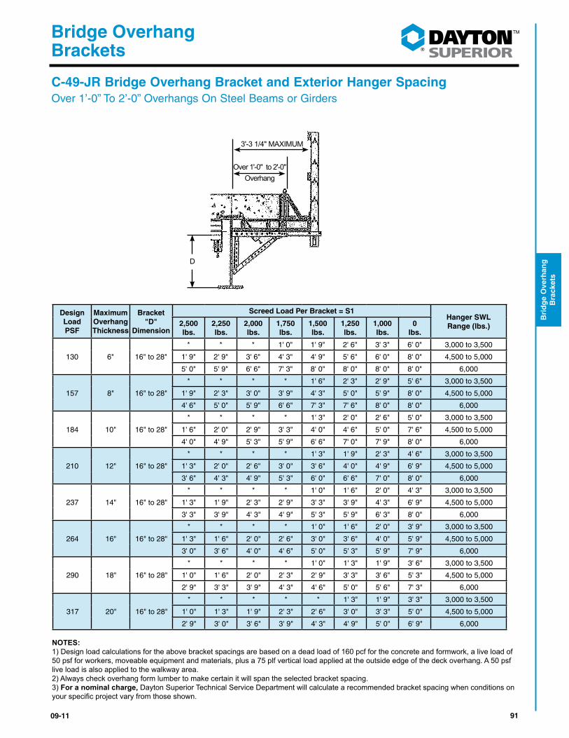
9109-11
®
Bridge Overhang Brackets
Bri
dg
e O
verh
ang
B
rack
ets
Design Load PSF
Maximum Overhang Thickness
Bracket "D"
Dimension
Screed Load Per Bracket = S1Hanger SWL Range (lbs.)2,500
lbs.2,250 lbs.
2,000 lbs.
1,750 lbs.
1,500 lbs.
1,250 lbs.
1,000 lbs.
0 lbs.
130 6" 16" to 28"
* * * 1' 0" 1' 9" 2' 6" 3' 3" 6' 0" 3,000 to 3,500
1' 9" 2' 9" 3' 6" 4' 3" 4' 9" 5' 6" 6' 0" 8' 0" 4,500 to 5,000
5' 0" 5' 9" 6' 6" 7' 3" 8' 0" 8' 0" 8' 0" 8' 0" 6,000
157 8" 16" to 28"
* * * * 1' 6" 2' 3" 2' 9" 5' 6" 3,000 to 3,500
1' 9" 2' 3" 3' 0" 3' 9" 4' 3" 5' 0" 5' 9" 8' 0" 4,500 to 5,000
4' 6" 5' 0" 5' 9" 6' 6" 7' 3" 7' 6" 8' 0" 8' 0" 6,000
184 10" 16" to 28"
* * * * 1' 3" 2' 0" 2' 6" 5' 0" 3,000 to 3,500
1' 6" 2' 0" 2' 9" 3' 3" 4' 0" 4' 6" 5' 0" 7' 6" 4,500 to 5,000
4' 0" 4' 9" 5' 3" 5' 9" 6' 6" 7' 0" 7' 9" 8' 0" 6,000
210 12" 16" to 28"
* * * * 1' 3" 1' 9" 2' 3" 4' 6" 3,000 to 3,500
1' 3" 2' 0" 2' 6" 3' 0" 3' 6" 4' 0" 4' 9" 6' 9" 4,500 to 5,000
3' 6" 4' 3" 4' 9" 5' 3" 6' 0" 6' 6" 7' 0" 8' 0" 6,000
237 14" 16" to 28"
* * * * 1' 0" 1' 6" 2' 0" 4' 3" 3,000 to 3,500
1' 3" 1' 9" 2' 3" 2' 9" 3' 3" 3' 9" 4' 3" 6' 9" 4,500 to 5,000
3' 3" 3' 9" 4' 3" 4' 9" 5' 3" 5' 9" 6' 3" 8' 0" 6,000
264 16" 16" to 28"
* * * * 1' 0" 1' 6" 2' 0" 3' 9" 3,000 to 3,500
1' 3" 1' 6" 2' 0" 2' 6" 3' 0" 3' 6" 4' 0" 5' 9" 4,500 to 5,000
3' 0" 3' 6" 4' 0" 4' 6" 5' 0" 5' 3" 5' 9" 7' 9" 6,000
290 18" 16" to 28"
* * * * 1' 0" 1' 3" 1' 9" 3' 6" 3,000 to 3,500
1' 0" 1' 6" 2' 0" 2' 3" 2' 9" 3' 3" 3' 6" 5' 3" 4,500 to 5,000
2' 9" 3' 3" 3' 9" 4' 3" 4' 6" 5' 0" 5' 6" 7' 3" 6,000
317 20" 16" to 28"
* * * * * 1' 3" 1' 9" 3' 3" 3,000 to 3,500
1' 0" 1' 3" 1' 9" 2' 3" 2' 6" 3' 0" 3' 3" 5' 0" 4,500 to 5,000
2' 9" 3' 0" 3' 6" 3' 9" 4' 3" 4' 9" 5' 0" 6' 9" 6,000
NOTES:1) Design load calculations for the above bracket spacings are based on a dead load of 160 pcf for the concrete and formwork, a live load of 50 psf for workers, moveable equipment and materials, plus a 75 plf vertical load applied at the outside edge of the deck overhang. A 50 psf live load is also applied to the walkway area. 2) Always check overhang form lumber to make certain it will span the selected bracket spacing.3) For a nominal charge, Dayton Superior Technical Service Department will calculate a recommended bracket spacing when conditions on yourspecificprojectvaryfromthoseshown.
C-49-JR Bridge Overhang Bracket and Exterior Hanger SpacingOver 1’-0” To 2’-0” Overhangs On Steel Beams or Girders
3'-3 1/4" MAXIMUM
Over 1'-0" to 2'-0"Overhang
D
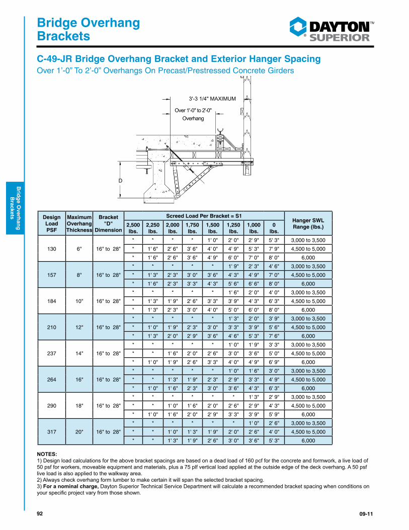
92 09-11
®
Bridge Overhang Brackets
Brid
ge O
verhan
g
Brackets
D
3'-3 1/4" MAXIMUM
Design Load PSF
Maximum Overhang Thickness
Bracket "D"
Dimension
Screed Load Per Bracket = S1Hanger SWL Range (lbs.)2,500
lbs.2,250 lbs.
2,000 lbs.
1,750 lbs.
1,500 lbs.
1,250 lbs.
1,000 lbs.
0 lbs.
130 6" 16" to 28"
* * * * 1' 0" 2' 0" 2' 9" 5' 3" 3,000 to 3,500
* 1' 6" 2' 6" 3' 6" 4' 0" 4' 9" 5' 3" 7' 9" 4,500 to 5,000
* 1' 6" 2' 6" 3' 6" 4' 9" 6' 0" 7' 0" 8' 0" 6,000
157 8" 16" to 28"
* * * * * 1' 9" 2' 3" 4' 6" 3,000 to 3,500
* 1' 3" 2' 3" 3' 0" 3' 6" 4' 3" 4' 9" 7' 0" 4,500 to 5,000
* 1' 6" 2' 3" 3' 3" 4' 3" 5' 6" 6' 6" 8' 0" 6,000
184 10" 16" to 28"
* * * * * 1' 6" 2' 0" 4' 0" 3,000 to 3,500
* 1' 3" 1' 9" 2' 6" 3' 3" 3' 9" 4' 3" 6' 3" 4,500 to 5,000
* 1' 3" 2' 3" 3' 0" 4' 0" 5' 0" 6' 0" 8' 0" 6,000
210 12" 16" to 28"
* * * * * 1' 3" 2' 0" 3' 9" 3,000 to 3,500
* 1' 0" 1' 9" 2' 3" 3' 0" 3' 3" 3' 9" 5' 6" 4,500 to 5,000
* 1' 3" 2' 0" 2' 9" 3' 6" 4' 6" 5' 3" 7' 6" 6,000
237 14" 16" to 28"
* * * * * 1' 0" 1' 9" 3' 3" 3,000 to 3,500
* * 1' 6" 2' 0" 2' 6" 3' 0" 3' 6" 5' 0" 4,500 to 5,000
* 1' 0" 1' 9" 2' 6" 3' 3" 4' 0" 4' 9" 6' 9" 6,000
264 16" 16" to 28"
* * * * * 1' 0" 1' 6" 3' 0" 3,000 to 3,500
* * 1' 3" 1' 9" 2' 3" 2' 9" 3' 3" 4' 9" 4,500 to 5,000
* 1' 0" 1' 6" 2' 3" 3' 0" 3' 6" 4' 3" 6' 3" 6,000
290 18" 16" to 28"
* * * * * * 1' 3" 2' 9" 3,000 to 3,500
* * 1' 0" 1' 6" 2' 0" 2' 6" 2' 9" 4' 3" 4,500 to 5,000
* 1' 0" 1' 6" 2' 0" 2' 9" 3' 3" 3' 9" 5' 9" 6,000
317 20" 16" to 28"
* * * * * * 1' 0" 2' 6" 3,000 to 3,500
* * 1' 0" 1' 3" 1' 9" 2' 0" 2' 6" 4' 0" 4,500 to 5,000
* * 1' 3" 1' 9" 2' 6" 3' 0" 3' 6" 5' 3" 6,000
NOTES:1) Design load calculations for the above bracket spacings are based on a dead load of 160 pcf for the concrete and formwork, a live load of 50 psf for workers, moveable equipment and materials, plus a 75 plf vertical load applied at the outside edge of the deck overhang. A 50 psf live load is also applied to the walkway area. 2) Always check overhang form lumber to make certain it will span the selected bracket spacing.3) For a nominal charge, Dayton Superior Technical Service Department will calculate a recommended bracket spacing when conditions on yourspecificprojectvaryfromthoseshown.
C-49-JR Bridge Overhang Bracket and Exterior Hanger SpacingOver 1’-0” To 2’-0” Overhangs On Precast/Prestressed Concrete Girders
Over 1'-0" to 2'-0"Overhang

9309-11
®
Bridge Overhang Brackets
Bri
dg
e O
verh
ang
B
rack
ets
D
B-16 3/4" x 6" CoilLoop Insert (TYP.)
Over 1'-0" to 2'-0"Overhang
3'-10" MAXIMUM
Design Load PSF
Maximum Overhang Thickness
Bracket "D"
Dimension
Screed Load Per Bracket = S1
2,500 lbs.
2,250 lbs.
2,000 lbs.
1,750 lbs.
1,500 lbs.
1,250 lbs.
1,000 lbs.
0 lbs.
130 6" 30" to 70" 3' 0" 4' 0" 4' 6" 5' 0" 5' 9" 6' 3" 7' 0" 8' 0"
157 8" 30" to 70" 2' 9" 3' 6" 4' 0" 4' 6" 5' 0" 5' 6" 6' 3" 8' 0"
184 10" 30" to 70" 2' 6" 3' 0" 3' 6" 4' 0" 4' 6" 5' 0" 5' 6" 7' 6"
210 12" 30" to 70" 2' 0" 2' 6" 3' 0" 3' 6" 4' 0" 4' 6" 5' 0" 6' 9"
237 14" 30" to 70" 2' 0" 2' 3" 2' 9" 3' 3" 3' 6" 4' 0" 4' 3" 6' 0"
264 16" 30" to 70" 1' 9" 2' 3" 2' 6" 2' 9" 3' 3" 3' 6" 4' 0" 5' 6"
290 18" 30" to 70" 1' 6" 2' 0" 2' 3" 2' 6" 3' 0" 3' 3" 3' 6" 5' 0"
317 20" 30" to 70" 1' 6" 1' 9" 2' 0" 2' 6" 2' 9" 3' 0" 3' 3" 4' 6"
NOTES:1) Design load calculations for the above bracket spacings are based on a dead load of 160 pcf for the concrete and formwork, a live load of 50 psf for workers, moveable equipment and materials, plus a 75 plf vertical load applied at the outside edge of the deck overhang. A 50 psf live load is also applied to the walkway area. 2) Always check overhang form lumber to make certain it will span the selected bracket spacing.3) For a nominal charge, Dayton Superior Technical Service Department will calculate a recommended bracket spacing when conditions on yourspecificprojectvaryfromthoseshown.
C-49 / C-49D Bridge Overhang Brackets with C-51 Wall Plate AssemblyOver 1’-0” To 2’-0” Overhangs On ConcreteWalls and Box Beams
D
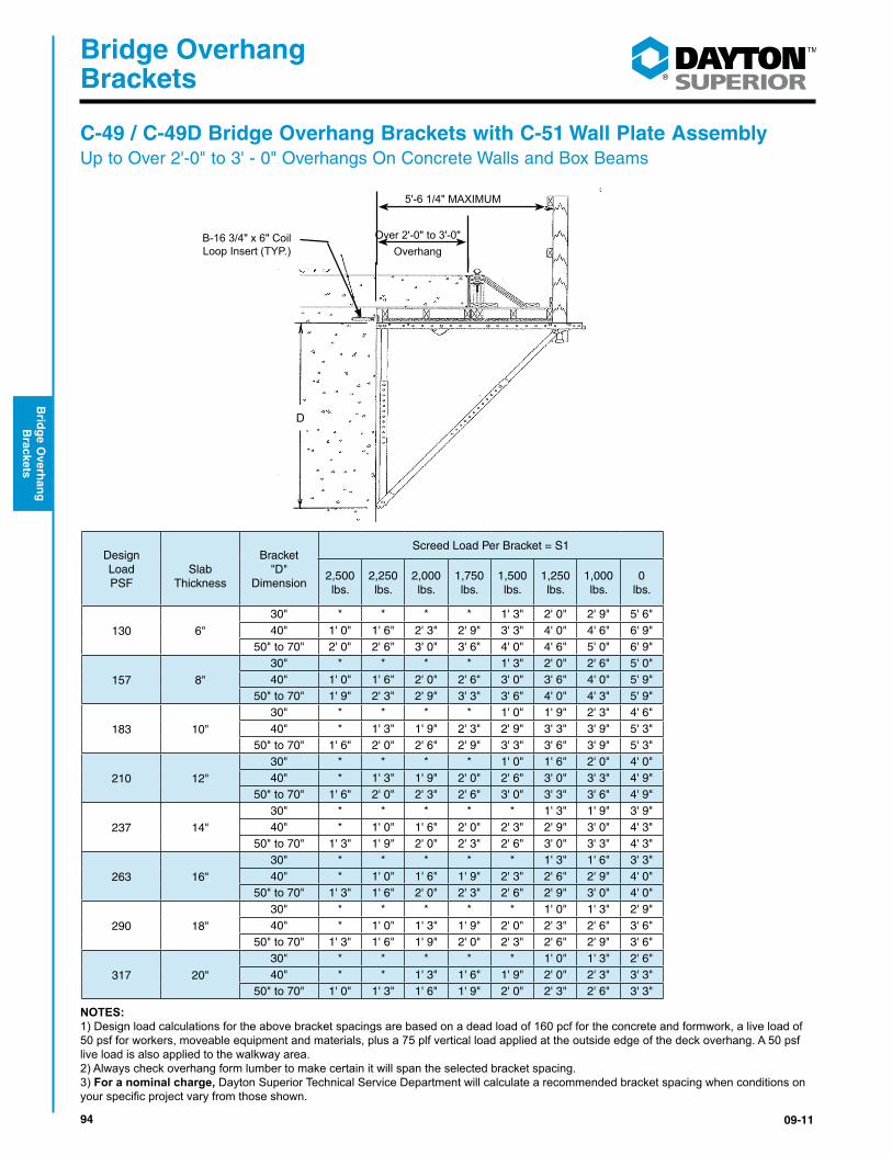
94 09-11
®
Bridge Overhang Brackets
Brid
ge O
verhan
g
Brackets
C-49 / C-49D Bridge Overhang Brackets with C-51 Wall Plate AssemblyUp to Over 2'-0" to 3' - 0" Overhangs On Concrete Walls and Box Beams
Design Load PSF
Slab
Thickness
Bracket "D"
Dimension
Screed Load Per Bracket = S1
2,500 lbs.
2,250 lbs.
2,000 lbs.
1,750 lbs.
1,500 lbs.
1,250 lbs.
1,000 lbs.
0 lbs.
130 6"
30" * * * * 1' 3" 2' 0" 2' 9" 5' 6" 40" 1' 0" 1' 6" 2' 3" 2' 9" 3' 3" 4' 0" 4' 6" 6' 9"
50" to 70" 2' 0" 2' 6" 3' 0" 3' 6" 4' 0" 4' 6" 5' 0" 6' 9"
157 8"
30" * * * * 1' 3" 2' 0" 2' 6" 5' 0" 40" 1' 0" 1' 6" 2' 0" 2' 6" 3' 0" 3' 6" 4' 0" 5' 9"
50" to 70" 1' 9" 2' 3" 2' 9" 3' 3" 3' 6" 4' 0" 4' 3" 5' 9"
183 10"
30" * * * * 1' 0" 1' 9" 2' 3" 4' 6" 40" * 1' 3" 1' 9" 2' 3" 2' 9" 3' 3" 3' 9" 5' 3"
50" to 70" 1' 6" 2' 0" 2' 6" 2' 9" 3' 3" 3' 6" 3' 9" 5' 3"
210 12"
30" * * * * 1' 0" 1' 6" 2' 0" 4' 0" 40" * 1' 3" 1' 9" 2' 0" 2' 6" 3' 0" 3' 3" 4' 9"
50" to 70" 1' 6" 2' 0" 2' 3" 2' 6" 3' 0" 3' 3" 3' 6" 4' 9"
237 14"
30" * * * * * 1' 3" 1' 9" 3' 9" 40" * 1' 0" 1' 6" 2' 0" 2' 3" 2' 9" 3' 0" 4' 3"
50" to 70" 1' 3" 1' 9" 2' 0" 2' 3" 2' 6" 3' 0" 3' 3" 4' 3"
263 16"
30" * * * * * 1' 3" 1' 6" 3' 3" 40" * 1' 0" 1' 6" 1' 9" 2' 3" 2' 6" 2' 9" 4' 0"
50" to 70" 1' 3" 1' 6" 2' 0" 2' 3" 2' 6" 2' 9" 3' 0" 4' 0"
290 18"
30" * * * * * 1' 0" 1' 3" 2' 9" 40" * 1' 0" 1' 3" 1' 9" 2' 0" 2' 3" 2' 6" 3' 6"
50" to 70" 1' 3" 1' 6" 1' 9" 2' 0" 2' 3" 2' 6" 2' 9" 3' 6"
317 20"
30" * * * * * 1' 0" 1' 3" 2' 6" 40" * * 1' 3" 1' 6" 1' 9" 2' 0" 2' 3" 3' 3"
50" to 70" 1' 0" 1' 3" 1' 6" 1' 9" 2' 0" 2' 3" 2' 6" 3' 3"
NOTES:1) Design load calculations for the above bracket spacings are based on a dead load of 160 pcf for the concrete and formwork, a live load of 50 psf for workers, moveable equipment and materials, plus a 75 plf vertical load applied at the outside edge of the deck overhang. A 50 psf live load is also applied to the walkway area. 2) Always check overhang form lumber to make certain it will span the selected bracket spacing.3) For a nominal charge, Dayton Superior Technical Service Department will calculate a recommended bracket spacing when conditions on yourspecificprojectvaryfromthoseshown.
D
B-16 3/4" x 6" CoilLoop Insert (TYP.)
Over 2'-0" to 3'-0"Overhang
5'-6 1/4" MAXIMUM
D
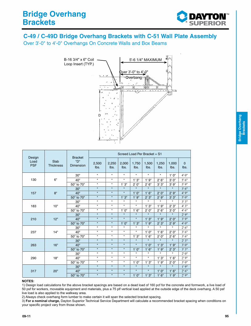
9509-11
®
Bridge Overhang Brackets
Bri
dg
e O
verh
ang
B
rack
ets
D
B-16 3/4" x 6" CoilLoop Insert (TYP.)
Over 3'-0" to 4'-0"Overhang
5'-6 1/4" MAXIMUM
C-49 / C-49D Bridge Overhang Brackets with C-51 Wall Plate AssemblyOver 3'-0" to 4'-0" Overhangs On Concrete Walls and Box Beams
Design Load PSF
Slab
Thickness
Bracket "D"
Dimension
Screed Load Per Bracket = S1
2,500 lbs.
2,250 lbs.
2,000 lbs.
1,750 lbs.
1,500 lbs.
1,250 lbs.
1,000 lbs.
0 lbs.
130 6" 30" * * * * * * 1' 0" 4' 0" 40" * * * 1' 3" 1' 9" 2' 6" 3' 0" 5' 6"
50" to 70" * * 1' 3" 2' 0" 2' 6" 3' 3" 3' 9" 5' 9"
157 8"30" * * * * * * * 3' 6" 40" * * * 1' 0" 1' 6" 2' 0" 2' 9" 4' 9"
50" to 70" * * 1' 3" 1' 9" 2' 3" 2' 9" 3' 3" 5' 0"
183 10"30" * * * * * * * 3' 3" 40" * * * * 1' 3" 1' 9" 2' 3" 4' 3"
50" to 70" * * 1' 0" 1' 6" 2' 0" 2' 6" 3' 0" 4' 6"
210 12"30" * * * * * * * 2' 9" 40" * * * * 1' 3" 1' 9" 2' 0" 3' 9"
50" to 70" * * 1' 0" 1' 3" 1' 9" 2' 3" 2' 9" 4' 0"
237 14"30" * * * * * * * 2' 6" 40" * * * * 1' 0" 1' 6" 2' 0" 3' 6"
50" to 70" * * * 1' 3" 1' 6" 2' 0" 2' 6" 3' 6"
263 16"30" * * * * * * * 2' 3" 40" * * * * 1' 0" 1' 3" 1' 9" 3' 0"
50" to 70" * * * 1' 0" 1' 6" 1' 9" 2' 3" 3' 3"
290 18"30" * * * * * * * 2' 0" 40" * * * * * 1' 3" 1' 6" 2' 9"
50" to 70" * * * 1' 0" 1' 3" 1' 9" 2' 0" 3' 0"
317 20"30" * * * * * * * 1' 9" 40" * * * * * 1' 0" 1' 6" 2' 6"
50" to 70" * * * 1' 0" 1' 3" 1' 6" 1' 9" 2' 9"
NOTES:1) Design load calculations for the above bracket spacings are based on a dead load of 160 pcf for the concrete and formwork, a live load of 50 psf for workers, moveable equipment and materials, plus a 75 plf vertical load applied at the outside edge of the deck overhang. A 50 psf live load is also applied to the walkway area. 2) Always check overhang form lumber to make certain it will span the selected bracket spacing.3) For a nominal charge, Dayton Superior Technical Service Department will calculate a recommended bracket spacing when conditions on yourspecificprojectvaryfromthoseshown.
D
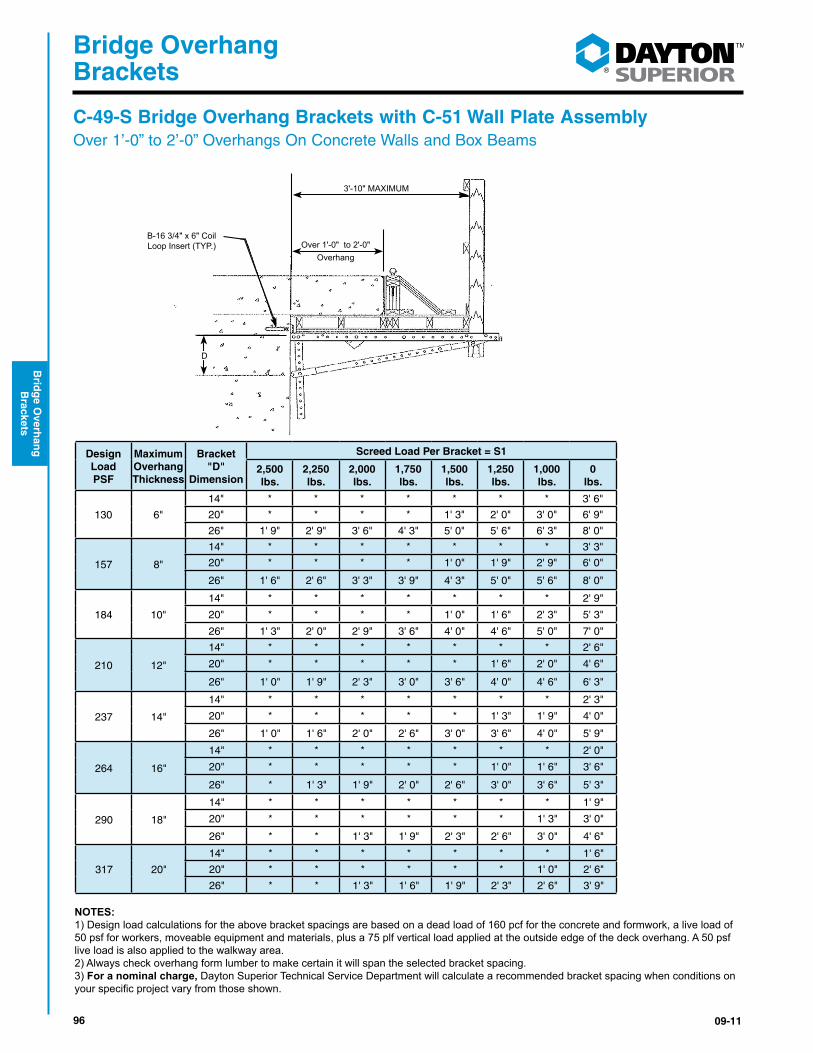
96 09-11
®
Bridge Overhang Brackets
Brid
ge O
verhan
g
Brackets
C-49-S Bridge Overhang Brackets with C-51 Wall Plate AssemblyOver 1’-0” to 2’-0” Overhangs On Concrete Walls and Box Beams
Design Load PSF
Maximum Overhang Thickness
Bracket "D"
Dimension
Screed Load Per Bracket = S1
2,500 lbs.
2,250 lbs.
2,000 lbs.
1,750 lbs.
1,500 lbs.
1,250 lbs.
1,000 lbs.
0 lbs.
130 6"
14" * * * * * * * 3' 6"
20" * * * * 1' 3" 2' 0" 3' 0" 6' 9"
26" 1' 9" 2' 9" 3' 6" 4' 3" 5' 0" 5' 6" 6' 3" 8' 0"
157 8"
14" * * * * * * * 3' 3"
20" * * * * 1' 0" 1' 9" 2' 9" 6' 0"
26" 1' 6" 2' 6" 3' 3" 3' 9" 4' 3" 5' 0" 5' 6" 8' 0"
184 10"
14" * * * * * * * 2' 9"
20" * * * * 1' 0" 1' 6" 2' 3" 5' 3"
26" 1' 3" 2' 0" 2' 9" 3' 6" 4' 0" 4' 6" 5' 0" 7' 0"
210 12"
14" * * * * * * * 2' 6"
20" * * * * * 1' 6" 2' 0" 4' 6"
26" 1' 0" 1' 9" 2' 3" 3' 0" 3' 6" 4' 0" 4' 6" 6' 3"
237 14"
14" * * * * * * * 2' 3"
20" * * * * * 1' 3" 1' 9" 4' 0"
26" 1' 0" 1' 6" 2' 0" 2' 6" 3' 0" 3' 6" 4' 0" 5' 9"
264 16"
14" * * * * * * * 2' 0"
20" * * * * * 1' 0" 1' 6" 3' 6"
26" * 1' 3" 1' 9" 2' 0" 2' 6" 3' 0" 3' 6" 5' 3"
290 18"
14" * * * * * * * 1' 9"
20" * * * * * * 1' 3" 3' 0"
26" * * 1' 3" 1' 9" 2' 3" 2' 6" 3' 0" 4' 6"
317 20"
14" * * * * * * * 1' 6"
20" * * * * * * 1' 0" 2' 6"
26" * * 1' 3" 1' 6" 1' 9" 2' 3" 2' 6" 3' 9"
NOTES:1) Design load calculations for the above bracket spacings are based on a dead load of 160 pcf for the concrete and formwork, a live load of 50 psf for workers, moveable equipment and materials, plus a 75 plf vertical load applied at the outside edge of the deck overhang. A 50 psf live load is also applied to the walkway area. 2) Always check overhang form lumber to make certain it will span the selected bracket spacing.3) For a nominal charge, Dayton Superior Technical Service Department will calculate a recommended bracket spacing when conditions on yourspecificprojectvaryfromthoseshown.
D
Over 1'-0" to 2'-0"Overhang
3'-10" MAXIMUM
B-16 3/4" x 6" CoilLoop Insert (TYP.)
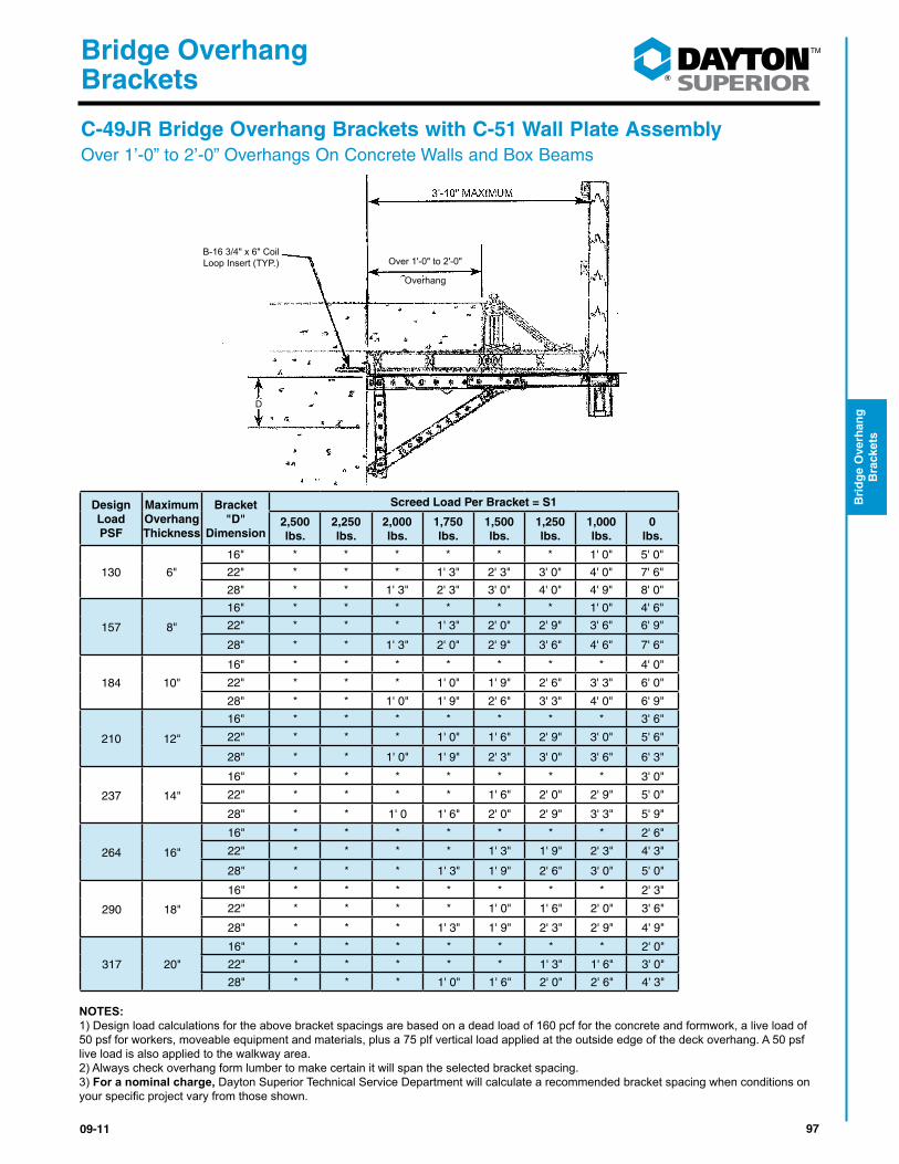
9709-11
®
Bridge Overhang Brackets
Bri
dg
e O
verh
ang
B
rack
ets
C-49JR Bridge Overhang Brackets with C-51 Wall Plate AssemblyOver 1’-0” to 2’-0” Overhangs On Concrete Walls and Box Beams
Design Load PSF
Maximum Overhang Thickness
Bracket "D"
Dimension
Screed Load Per Bracket = S1
2,500 lbs.
2,250 lbs.
2,000 lbs.
1,750 lbs.
1,500 lbs.
1,250 lbs.
1,000 lbs.
0 lbs.
130 6"
16" * * * * * * 1' 0" 5' 0"
22" * * * 1' 3" 2' 3" 3' 0" 4' 0" 7' 6"
28" * * 1' 3" 2' 3" 3' 0" 4' 0" 4' 9" 8' 0"
157 8"
16" * * * * * * 1' 0" 4' 6"
22" * * * 1' 3" 2' 0" 2' 9" 3' 6" 6' 9"
28" * * 1' 3" 2' 0" 2' 9" 3' 6" 4' 6" 7' 6"
184 10"
16" * * * * * * * 4' 0"
22" * * * 1' 0" 1' 9" 2' 6" 3' 3" 6' 0"
28" * * 1' 0" 1' 9" 2' 6" 3' 3" 4' 0" 6' 9"
210 12"
16" * * * * * * * 3' 6"
22" * * * 1' 0" 1' 6" 2' 9" 3' 0" 5' 6"
28" * * 1' 0" 1' 9" 2' 3" 3' 0" 3' 6" 6' 3"
237 14"
16" * * * * * * * 3' 0"
22" * * * * 1' 6" 2' 0" 2' 9" 5' 0"
28" * * 1' 0 1' 6" 2' 0" 2' 9" 3' 3" 5' 9"
264 16"
16" * * * * * * * 2' 6"
22" * * * * 1' 3" 1' 9" 2' 3" 4' 3"
28" * * * 1' 3" 1' 9" 2' 6" 3' 0" 5' 0"
290 18"
16" * * * * * * * 2' 3"
22" * * * * 1' 0" 1' 6" 2' 0" 3' 6"
28" * * * 1' 3" 1' 9" 2' 3" 2' 9" 4' 9"
317 20"
16" * * * * * * * 2' 0"
22" * * * * * 1' 3" 1' 6" 3' 0"
28" * * * 1' 0" 1' 6" 2' 0" 2' 6" 4' 3"
NOTES:1) Design load calculations for the above bracket spacings are based on a dead load of 160 pcf for the concrete and formwork, a live load of 50 psf for workers, moveable equipment and materials, plus a 75 plf vertical load applied at the outside edge of the deck overhang. A 50 psf live load is also applied to the walkway area. 2) Always check overhang form lumber to make certain it will span the selected bracket spacing.3) For a nominal charge, Dayton Superior Technical Service Department will calculate a recommended bracket spacing when conditions on yourspecificprojectvaryfromthoseshown.
3'-10" MAXIMUM
Overhang
Over 1'-0" to 2'-0"B-16 3/4" x 6" CoilLoop Insert (TYP.)
D
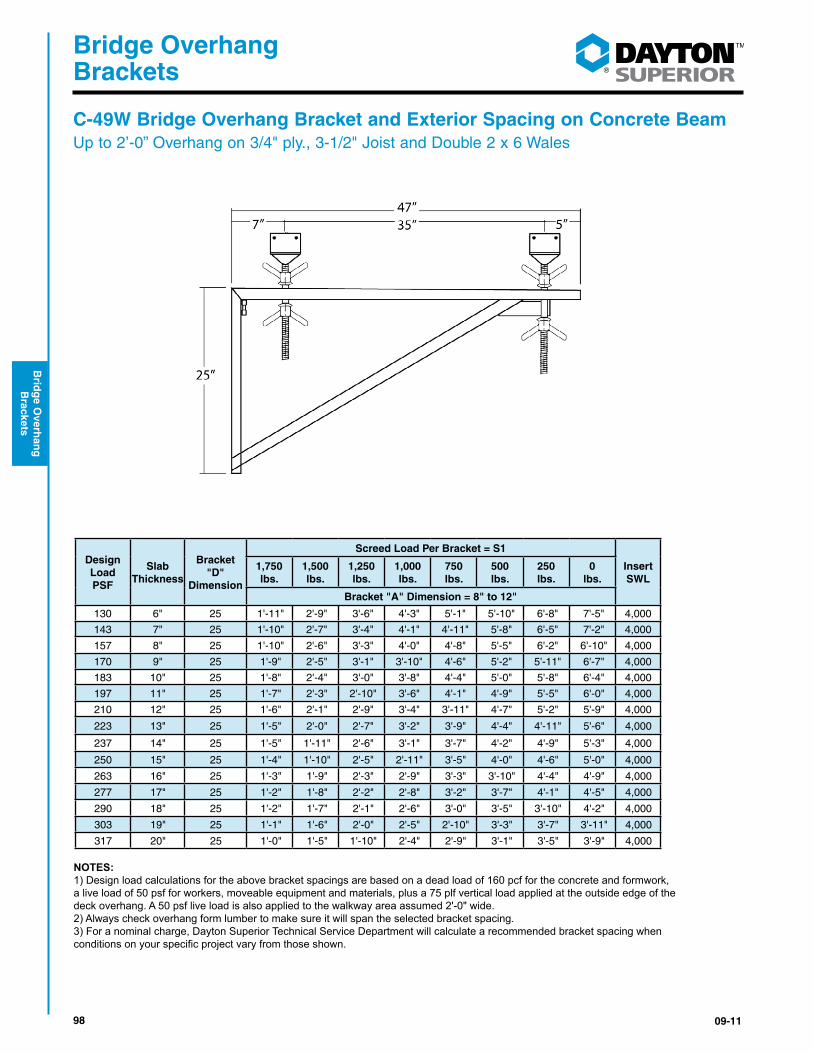
98 09-11
®
Bridge Overhang Brackets
Brid
ge O
verhan
g
Brackets
Design Load PSF
Slab Thickness
Bracket "D"
Dimension
Screed Load Per Bracket = S1
Insert SWL
1,750 lbs.
1,500 lbs.
1,250 lbs.
1,000 lbs.
750 lbs.
500 lbs.
250 lbs.
0 lbs.
Bracket "A" Dimension = 8" to 12"
130 6" 25 1'-11" 2'-9" 3'-6" 4'-3" 5'-1" 5'-10" 6'-8" 7'-5" 4,000
143 7" 25 1'-10" 2'-7" 3'-4" 4'-1" 4'-11" 5'-8" 6'-5" 7'-2" 4,000
157 8" 25 1'-10" 2'-6" 3'-3" 4'-0" 4'-8" 5'-5" 6'-2" 6'-10" 4,000
170 9" 25 1'-9" 2'-5" 3'-1" 3'-10" 4'-6" 5'-2" 5'-11" 6'-7" 4,000
183 10" 25 1'-8" 2'-4" 3'-0" 3'-8" 4'-4" 5'-0" 5'-8" 6'-4" 4,000
197 11" 25 1'-7" 2'-3" 2'-10" 3'-6" 4'-1" 4'-9" 5'-5" 6'-0" 4,000
210 12" 25 1'-6" 2'-1" 2'-9" 3'-4" 3'-11" 4'-7" 5'-2" 5'-9" 4,000
223 13" 25 1'-5" 2'-0" 2'-7" 3'-2" 3'-9" 4'-4" 4'-11" 5'-6" 4,000
237 14" 25 1'-5" 1'-11" 2'-6" 3'-1" 3'-7" 4'-2" 4'-9" 5'-3" 4,000
250 15" 25 1'-4" 1'-10" 2'-5" 2'-11" 3'-5" 4'-0" 4'-6" 5'-0" 4,000
263 16" 25 1'-3" 1'-9" 2'-3" 2'-9" 3'-3" 3'-10" 4'-4" 4'-9" 4,000
277 17" 25 1'-2" 1'-8" 2'-2" 2'-8" 3'-2" 3'-7" 4'-1" 4'-5" 4,000
290 18" 25 1'-2" 1'-7" 2'-1" 2'-6" 3'-0" 3'-5" 3'-10" 4'-2" 4,000
303 19" 25 1'-1" 1'-6" 2'-0" 2'-5" 2'-10" 3'-3" 3'-7" 3'-11" 4,000
317 20" 25 1'-0" 1'-5" 1'-10" 2'-4" 2'-9" 3'-1" 3'-5" 3'-9" 4,000
NOTES:1) Design load calculations for the above bracket spacings are based on a dead load of 160 pcf for the concrete and formwork,a live load of 50 psf for workers, moveable equipment and materials, plus a 75 plf vertical load applied at the outside edge of thedeck overhang. A 50 psf live load is also applied to the walkway area assumed 2'-0" wide.2) Always check overhang form lumber to make sure it will span the selected bracket spacing.3) For a nominal charge, Dayton Superior Technical Service Department will calculate a recommended bracket spacing whenconditionsonyourspecificprojectvaryfromthoseshown.
C-49W Bridge Overhang Bracket and Exterior Spacing on Concrete BeamUp to 2’-0” Overhang on 3/4" ply., 3-1/2" Joist and Double 2 x 6 Wales
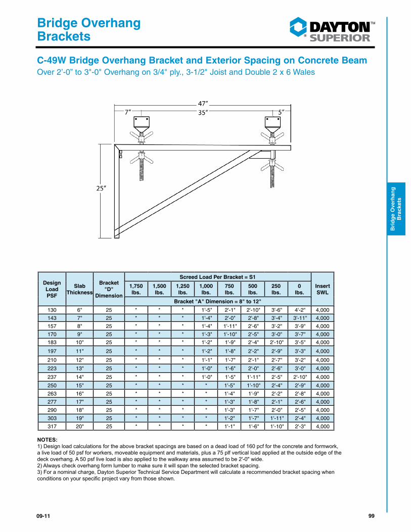
9909-11
®
Bridge Overhang Brackets
Bri
dg
e O
verh
ang
B
rack
ets
Design Load PSF
Slab Thickness
Bracket "D"
Dimension
Screed Load Per Bracket = S1
Insert SWL
1,750 lbs.
1,500 lbs.
1,250 lbs.
1,000 lbs.
750 lbs.
500 lbs.
250 lbs.
0 lbs.
Bracket "A" Dimension = 8" to 12"
130 6" 25 * * * 1'-5" 2'-1" 2'-10" 3'-6" 4'-2" 4,000
143 7" 25 * * * 1'-4" 2'-0" 2'-8" 3'-4" 3'-11" 4,000
157 8" 25 * * * 1'-4" 1'-11" 2'-6" 3'-2" 3'-9" 4,000
170 9" 25 * * * 1'-3" 1'-10" 2'-5" 3'-0" 3'-7" 4,000
183 10" 25 * * * 1'-2" 1'-9" 2'-4" 2'-10" 3'-5" 4,000
197 11" 25 * * * 1'-2" 1'-8" 2'-2" 2'-9" 3'-3" 4,000
210 12" 25 * * * 1'-1" 1'-7" 2'-1" 2'-7" 3'-2" 4,000
223 13" 25 * * * 1'-0" 1'-6" 2'-0" 2'-6" 3'-0" 4,000
237 14" 25 * * * 1'-0" 1'-5" 1'-11" 2'-5" 2'-10" 4,000
250 15" 25 * * * * 1'-5" 1'-10" 2'-4" 2'-9" 4,000
263 16" 25 * * * * 1'-4" 1'-9" 2'-2" 2'-8" 4,000
277 17" 25 * * * * 1'-3" 1'-8" 2'-1" 2'-6" 4,000
290 18" 25 * * * * 1'-3" 1'-7" 2'-0" 2'-5" 4,000
303 19" 25 * * * * 1'-2" 1'-7" 1'-11" 2'-4" 4,000
317 20" 25 * * * * 1'-1" 1'-6" 1'-10" 2'-3" 4,000
NOTES:1) Design load calculations for the above bracket spacings are based on a dead load of 160 pcf for the concrete and formwork,a live load of 50 psf for workers, moveable equipment and materials, plus a 75 plf vertical load applied at the outside edge of thedeck overhang. A 50 psf live load is also applied to the walkway area assumed to be 2'-0" wide.2) Always check overhang form lumber to make sure it will span the selected bracket spacing.3) For a nominal charge, Dayton Superior Technical Service Department will calculate a recommended bracket spacing whenconditionsonyourspecificprojectvaryfromthoseshown.
C-49W Bridge Overhang Bracket and Exterior Spacing on Concrete BeamOver 2’-0” to 3"-0" Overhang on 3/4" ply., 3-1/2" Joist and Double 2 x 6 Wales

100 09-11
®
Bridge Overhang Brackets
Brid
ge O
verhan
g
Brackets
Design Load PSF
Slab Thickness
Bracket "D"
Dimension
Screed Load Per Bracket = S1Insert SWL1,500 lbs. 1,250 lbs. 750 lbs. 500 lbs. 250 lbs. 0 lbs.
Bracket "A" Dimension = 18" to 20"
125 6"
30"7'-11" 8'-0" 8'-0" 8'-0" 8'-0" 8'-0" 8000
8'-0" 8'-0" 8'-0" 8'-0" 8'-0" 8'-0" 11300
45"7'-11" 8'-0" 8'-0" 8'-0" 8'-0" 8'-0" 8000
8'-0" 8'-0" 8'-0" 8'-0" 8'-0" 8'-0" 11300
60"7'-11" 8'-0" 8'-0" 8'-0" 8'-0" 8'-0" 8000
8'-0" 8'-0" 8'-0" 8'-0" 8'-0" 8'-0" 11300
150 8"
30"6'-9" 7'-2" 8'-0" 8'-0" 8'-0" 8'-0" 8000
7'-5" 8'-0" 8'-0" 8'-0" 8'-0" 8'-0" 11300
45"6'-9" 7'-2" 8'-0" 8'-0" 8'-0" 8'-0" 8000
8'-0" 8'-0" 8'-0" 8'-0" 8'-0" 8'-0" 11300
60"6'-9" 7'-2" 8'-0" 8'-0" 8'-0" 8'-0" 8000
8'-0" 8'-0" 8'-0" 8'-0" 8'-0" 8'-0" 11300
175 10"
30"5'-11" 6'-3" 7'-0" 7'-4" 7'-8" 8'-0" 8000
6'-9" 7'-3" 8'-0" 8'-0" 8'-0" 8'-0" 11300
45"6'-0" 6'-3" 7'-0" 7'-4" 7'-8" 8'-0" 8000
8'-0" 8'-0" 8'-0" 8'-0" 8'-0" 8'-0" 11300
60"6'-0" 6'-3" 7'-0" 7'-4" 7'-8" 8'-0" 8000
8'-0" 8'-0" 8'-0" 8'-0" 8'-0" 8'-0" 11300
200 12"
30"5' 3" 5'-7" 6'-3" 6'-8" 7'-0" 7'-4" 8000
6'-0" 6'-9" 8'-0" 8'-0" 8'-0" 8'-0" 11300
45"5' 3" 5'-7" 6'-3" 6'-8" 7'-0" 7'-4" 8000
8'-0" 8'-0" 8'-0" 8'-0" 8'-0" 8'-0" 11300
60"5' 3" 5'-7" 6'-3" 6'-8" 7'-0" 7'-4" 8000
8'-0" 8'-0" 8'-0" 8'-0" 8'-0" 8'-0" 11300
Note: Design includes 50 PSF live load on walkway area.Overhang form lumber must be checked to mae sure it will span the selected spacing.Warning: Contact Dayton Superior Technical Service Department for recommended spacings when conditions on your specific project vary from those shown.
C-89 Heavy Duty Bridge Overhang Bracket (72")Up to 4'-0" Overhangs on Steel Girders
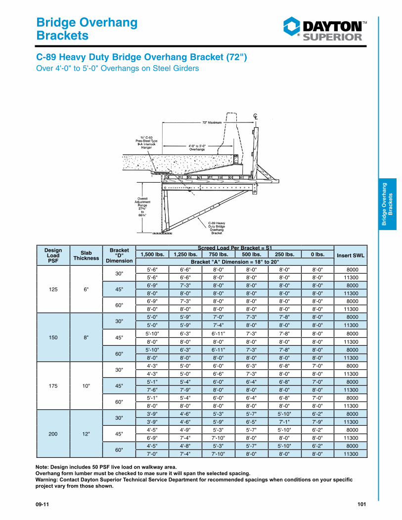
10109-11
®
Bridge Overhang Brackets
Bri
dg
e O
verh
ang
B
rack
ets
Design Load PSF
Slab Thickness
Bracket "D"
Dimension
Screed Load Per Bracket = S1Insert SWL1,500 lbs. 1,250 lbs. 750 lbs. 500 lbs. 250 lbs. 0 lbs.
Bracket "A" Dimension = 18" to 20"
125 6"
30"5'-6" 6'-6" 8'-0" 8'-0" 8'-0" 8'-0" 8000
5'-6" 6'-6" 8'-0" 8'-0" 8'-0" 8'-0" 11300
45"6'-9" 7'-3" 8'-0" 8'-0" 8'-0" 8'-0" 8000
8'-0" 8'-0" 8'-0" 8'-0" 8'-0" 8'-0" 11300
60"6'-9" 7'-3" 8'-0" 8'-0" 8'-0" 8'-0" 8000
8'-0" 8'-0" 8'-0" 8'-0" 8'-0" 8'-0" 11300
150 8"
30"5'-0" 5'-9" 7'-0" 7'-3" 7'-8" 8'-0" 8000
5'-0" 5'-9" 7'-4" 8'-0" 8'-0" 8'-0" 11300
45"5'-10" 6'-3" 6'-11" 7'-3" 7'-8" 8'-0" 8000
8'-0" 8'-0" 8'-0" 8'-0" 8'-0" 8'-0" 11300
60"5'-10" 6'-3" 6'-11" 7'-3" 7'-8" 8'-0" 8000
8'-0" 8'-0" 8'-0" 8'-0" 8'-0" 8'-0" 11300
175 10"
30"4'-3" 5'-0" 6'-0" 6'-3" 6'-8" 7'-0" 8000
4'-3" 5'-0" 6'-6" 7'-3" 8'-0" 8'-0" 11300
45"5'-1" 5'-4" 6'-0" 6'-4" 6'-8" 7'-0" 8000
7'-6" 7'-9" 8'-0" 8'-0" 8'-0" 8'-0" 11300
60"5'-1" 5'-4" 6'-0" 6'-4" 6'-8" 7'-0" 8000
8'-0" 8'-0" 8'-0" 8'-0" 8'-0" 8'-0" 11300
200 12"
30"3'-9" 4'-6" 5'-3" 5'-7" 5'-10" 6'-2" 8000
3'-9" 4'-6" 5'-9" 6'-5" 7'-1" 7'-9" 11300
45"4'-5" 4'-9" 5'-3" 5'-7" 5'-10" 6'-2" 8000
6'-9" 7'-4" 7'-10" 8'-0" 8'-0" 8'-0" 11300
60"4'-5" 4'-8" 5'-3" 5'-7" 5'-10" 6'-2" 8000
7'-0" 7'-4" 7'-10" 8'-0" 8'-0" 8'-0" 11300
Note: Design includes 50 PSF live load on walkway area.Overhang form lumber must be checked to mae sure it will span the selected spacing.Warning: Contact Dayton Superior Technical Service Department for recommended spacings when conditions on your specific project vary from those shown.
C-89 Heavy Duty Bridge Overhang Bracket (72")Over 4'-0" to 5'-0" Overhangs on Steel Girders

102 09-11
®
Bridge Overhang Brackets
Brid
ge O
verhan
g
Brackets
Design Load PSF
Slab Thickness
Bracket "D"
Dimension
Screed Load Per Bracket = S1Insert SWL1,500 lbs. 1,250 lbs. 750 lbs. 500 lbs. 250 lbs. 0 lbs.
Bracket "A" Dimension = 12" to 16"
125 6"
30"7'-8" 8'-0" 8'-0" 8'-0" 8'-0" 8'-0" 8000
8'-0" 8'-0" 8'-0" 8'-0" 8'-0" 8'-0" 11300
45"7'-8" 8'-0" 8'-0" 8'-0" 8'-0" 8'-0" 8000
8'-0" 8'-0" 8'-0" 8'-0" 8'-0" 8'-0" 11300
60"7'-8" 8'-0" 8'-0" 8'-0" 8'-0" 8'-0" 8000
8'-0" 8'-0" 8'-0" 8'-0" 8'-0" 8'-0" 11300
150 8"
30"6'-8" 7'-1" 8'-0" 8'-0" 8'-0" 8'-0" 8000
8'-0" 8'-0" 8'-0" 8'-0" 8'-0" 8'-0" 11300
45"6'-8" 7'-1" 8'-0" 8'-0" 8'-0" 8'-0" 8000
8'-0" 8'-0" 8'-0" 8'-0" 8'-0" 8'-0" 11300
60"6'-8" 7'-1" 8'-0" 8'-0" 8'-0" 8'-0" 8000
8'-0" 8'-0" 8'-0" 8'-0" 8'-0" 8'-0" 11300
175 10"
30"6'-0" 6'-4" 7'-1" 7'-5" 7'-10" 8'-0" 8000
8'-0" 8'-0" 8'-0" 8'-0" 8'-0" 8'-0" 11300
45"6'-0" 6'-4" 7'-1" 7'-5" 7'-10" 8'-0" 8000
8'-0" 8'-0" 8'-0" 8'-0" 8'-0" 8'-0" 11300
60"6'-0" 6'-4" 7'-1" 7'-5" 7'-10" 8'-0" 8000
8'-0" 8'-0" 8'-0" 8'-0" 8'-0" 8'-0" 11300
200 12"
30"5' 4" 5'-8" 6'-4" 6'-8" 7'-0" 7'-4" 8000
8'-0" 8'-0" 8'-0" 8'-0" 8'-0" 8'-0" 11300
45"5' 4" 5'-8" 6'-4" 6'-8" 7'-0" 7'-4" 8000
8'-0" 8'-0" 8'-0" 8'-0" 8'-0" 8'-0" 11300
60"5' 4" 5'-8" 6'-4" 6'-8" 7'-0" 7'-4" 8000
8'-0" 8'-0" 8'-0" 8'-0" 8'-0" 8'-0" 11300
Note: Design includes 50 PSF live load on walkway area.Overhang form lumber must be checked to mae sure it will span the selected spacing.Warning: Contact Dayton Superior Technical Service Department for recommended spacings when conditions on your specific project vary from those shown.
C-89 Heavy Duty Bridge Overhang Bracket (72")Up to 3'-0" Overhangs on Precast/Prestressed Concrete Girders
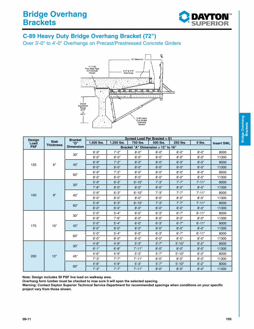
10309-11
®
Bridge Overhang Brackets
Bri
dg
e O
verh
ang
B
rack
ets
Design Load PSF
Slab Thickness
Bracket "D"
Dimension
Screed Load Per Bracket = S1Insert SWL1,500 lbs. 1,250 lbs. 750 lbs. 500 lbs. 250 lbs. 0 lbs.
Bracket "A" Dimension = 12" to 16"
125 6"
30"6'-9" 7'-2" 8'-0" 8'-0" 8'-0" 8'-0" 8000
8'-0" 8'-0" 8'-0" 8'-0" 8'-0" 8'-0" 11300
45"6'-9" 7'-2" 8'-0" 8'-0" 8'-0" 8'-0" 8000
8'-0" 8'-0" 8'-0" 8'-0" 8'-0" 8'-0" 11300
60"6'-9" 7'-2" 8'-0" 8'-0" 8'-0" 8'-0" 8000
8'-0" 8'-0" 8'-0" 8'-0" 8'-0" 8'-0" 11300
150 8"
30"5'-9" 6'-3" 6'-10" 7'-3" 7'-7" 7'-11" 8000
7'-8" 8'-0" 8'-0" 8'-0" 8'-0" 8'-0" 11300
45"5'-9" 6'-3" 6'-10" 7'-3" 7'-7" 7'-11" 8000
8'-0" 8'-0" 8'-0" 8'-0" 8'-0" 8'-0" 11300
60"5'-9" 6'-3" 6'-10" 7'-3" 7'-7" 7'-11" 8000
8'-0" 8'-0" 8'-0" 8'-0" 8'-0" 8'-0" 11300
175 10"
30"5'-0" 5'-4" 6'-0" 6'-3" 6'-7" 6'-11" 8000
6'-9" 7'-6" 8'-0" 8'-0" 8'-0" 8'-0" 11300
45"5'-0" 5'-4" 6'-0" 6'-3" 6'-7" 6'-11" 8000
8'-0" 8'-0" 8'-0" 8'-0" 8'-0" 8'-0" 11300
60"5'-0" 5'-4" 6'-0" 6'-3" 6'-7" 6'-11" 8000
8'-0" 8'-0" 8'-0" 8'-0" 8'-0" 8'-0" 11300
200 12"
30"4'-6" 4'-9" 5'-3" 5'-7" 5'-10" 6'-2" 8000
6'-1" 6'-8" 7'-11" 8'-0" 8'-0" 8'-0" 11300
45"4'-6" 4'-9" 5'-3" 5'-7" 5'-10" 6'-2" 8000
7'-3" 7'-7" 7'-11" 8'-0" 8'-0" 8'-0" 11300
60"4'-6" 4'-9" 5'-3" 5'-7" 5'-10" 6'-2" 8000
7'-3" 7'-7" 7'-11" 8'-0" 8'-0" 8'-0" 11300
Note: Design includes 50 PSF live load on walkway area.Overhang form lumber must be checked to mae sure it will span the selected spacing.Warning: Contact Dayton Superior Technical Service Department for recommended spacings when conditions on your specific project vary from those shown.
C-89 Heavy Duty Bridge Overhang Bracket (72")Over 3'-0" to 4'-0" Overhangs on Precast/Prestressed Concrete Girders
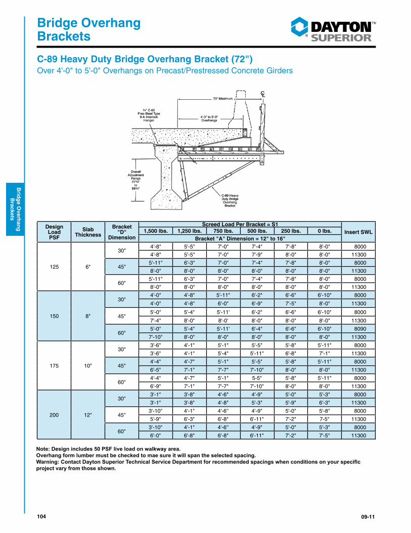
104 09-11
®
Bridge Overhang Brackets
Brid
ge O
verhan
g
Brackets
Design Load PSF
Slab Thickness
Bracket "D"
Dimension
Screed Load Per Bracket = S1Insert SWL1,500 lbs. 1,250 lbs. 750 lbs. 500 lbs. 250 lbs. 0 lbs.
Bracket "A" Dimension = 12" to 16"
125 6"
30"4'-8" 5'-5" 7'-0" 7'-4" 7'-8" 8'-0" 8000
4'-8" 5'-5" 7'-0" 7'-9" 8'-0" 8'-0" 11300
45"5'-11" 6'-3" 7'-0" 7'-4" 7'-8" 8'-0" 8000
8'-0" 8'-0" 8'-0" 8'-0" 8'-0" 8'-0" 11300
60"5'-11" 6'-3" 7'-0" 7'-4" 7'-8" 8'-0" 8000
8'-0" 8'-0" 8'-0" 8'-0" 8'-0" 8'-0" 11300
150 8"
30"4'-0" 4'-8" 5'-11" 6'-2" 6'-6" 6'-10" 8000
4'-0" 4'-8" 6'-0" 6'-9" 7'-5" 8'-0" 11300
45"5'-0" 5'-4" 5'-11' 6'-2" 6'-6" 6'-10" 8000
7'-4" 8'-0" 8'-0' 8'-0" 8'-0" 8'-0" 11300
60"5'-0" 5'-4" 5'-11' 6'-4" 6'-6" 6'-10" 8090
7'-10" 8'-0" 8'-0" 8'-0" 8'-0" 8'-0" 11300
175 10"
30"3'-6" 4'-1" 5'-1" 5'-5" 5'-8" 5'-11" 8000
3'-6" 4'-1" 5'-4" 5'-11" 6'-8" 7'-1" 11300
45"4'-4" 4'-7" 5'-1" 5'-5" 5'-8" 5'-11" 8000
6'-5" 7'-1" 7'-7" 7'-10" 8'-0" 8'-0" 11300
60"4'-4" 4'-7" 5'-1" 5-5" 5'-8" 5'-11" 8000
6'-9" 7'-1" 7'-7" 7'-10" 8'-0" 8'-0" 11300
200 12"
30"3'-1" 3'-8" 4'-6" 4'-9" 5'-0" 5'-3" 8000
3'-1" 3'-8" 4'-8" 5'-3" 5'-9" 6'-3" 11300
45"3'-10" 4'-1" 4'-6'' 4'-9" 5'-0" 5'-8" 8000
5'-9" 6'-3" 6'-8" 6'-11" 7'-2" 7-5" 11300
60"3'-10" 4'-1" 4'-6'' 4'-9" 5'-0" 5'-3" 8000
6'-0" 6'-8" 6'-8" 6'-11" 7'-2" 7'-5" 11300
Note: Design includes 50 PSF live load on walkway area.Overhang form lumber must be checked to mae sure it will span the selected spacing.Warning: Contact Dayton Superior Technical Service Department for recommended spacings when conditions on your specific project vary from those shown.
C-89 Heavy Duty Bridge Overhang Bracket (72")Over 4'-0" to 5'-0" Overhangs on Precast/Prestressed Concrete Girders
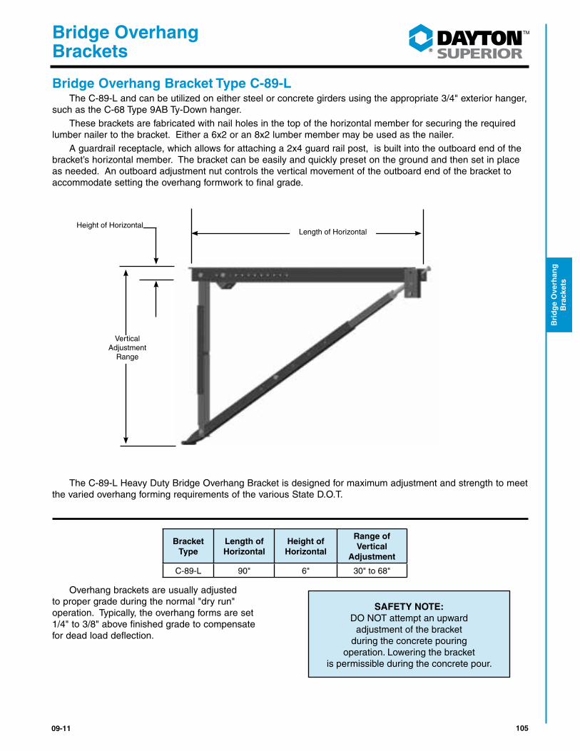
10509-11
®
Bridge Overhang Brackets
Bri
dg
e O
verh
ang
B
rack
ets
Bridge Overhang Bracket Type C-89-L The C-89-L and can be utilized on either steel or concrete girders using the appropriate 3/4" exterior hanger, such as the C-68 Type 9AB Ty-Down hanger. These brackets are fabricated with nail holes in the top of the horizontal member for securing the required lumber nailer to the bracket. Either a 6x2 or an 8x2 lumber member may be used as the nailer. A guardrail receptacle, which allows for attaching a 2x4 guard rail post, is built into the outboard end of the bracket’s horizontal member. The bracket can be easily and quickly preset on the ground and then set in place as needed. An outboard adjustment nut controls the vertical movement of the outboard end of the bracket to accommodate setting the overhang formwork to final grade.
The C-89-L Heavy Duty Bridge Overhang Bracket is designed for maximum adjustment and strength to meet the varied overhang forming requirements of the various State D.O.T.
Overhang brackets are usually adjusted to proper grade during the normal "dry run" operation. Typically, the overhang forms are set 1/4" to 3/8" above finished grade to compensate for dead load deflection.
SAFETY NOTE:DO NOT attempt an upward
adjustment of the bracket during the concrete pouring
operation. Lowering the bracket is permissible during the concrete pour.
Bracket Type
Length of Horizontal
Height of Horizontal
Range of Vertical
Adjustment
C-89-L 90" 6" 30" to 68"
Length of Horizontal
Vertical Adjustment
Range
Height of Horizontal
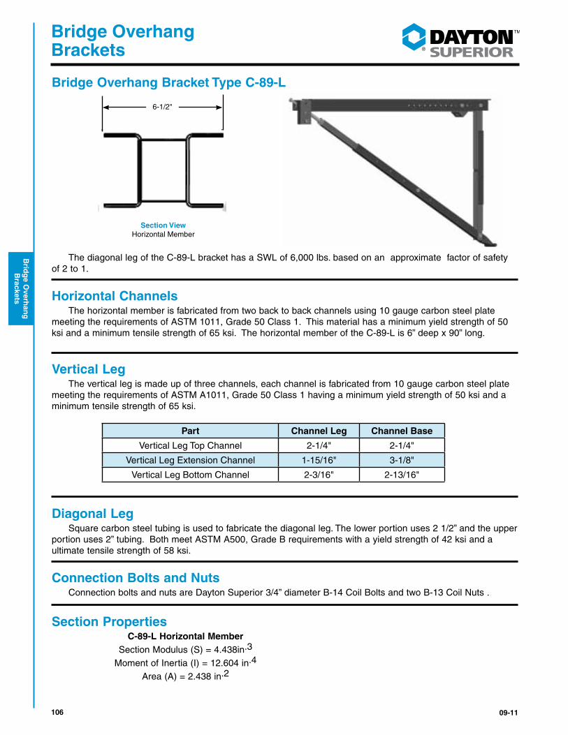
106 09-11
®
Bridge Overhang Brackets
Brid
ge O
verhan
g
Brackets
Bridge Overhang Bracket Type C-89-L
The diagonal leg of the C-89-L bracket has a SWL of 6,000 lbs. based on an approximate factor of safety of 2 to 1.
Horizontal Channels The horizontal member is fabricated from two back to back channels using 10 gauge carbon steel plate meeting the requirements of ASTM 1011, Grade 50 Class 1. This material has a minimum yield strength of 50 ksi and a minimum tensile strength of 65 ksi. The horizontal member of the C-89-L is 6” deep x 90” long.
Vertical Leg The vertical leg is made up of three channels, each channel is fabricated from 10 gauge carbon steel plate meeting the requirements of ASTM A1011, Grade 50 Class 1 having a minimum yield strength of 50 ksi and a minimum tensile strength of 65 ksi.
Diagonal Leg Square carbon steel tubing is used to fabricate the diagonal leg. The lower portion uses 2 1/2” and the upper portion uses 2” tubing. Both meet ASTM A500, Grade B requirements with a yield strength of 42 ksi and a ultimate tensile strength of 58 ksi.
Connection Bolts and Nuts Connection bolts and nuts are Dayton Superior 3/4” diameter B-14 Coil Bolts and two B-13 Coil Nuts .
Section Properties C-89-L Horizontal Member Section Modulus (S) = 4.438in.3
Moment of Inertia (I) = 12.604 in.4
Area (A) = 2.438 in.2
6-1/2"
Section ViewHorizontal Member
Part Channel Leg Channel Base
Vertical Leg Top Channel 2-1/4" 2-1/4"
Vertical Leg Extension Channel 1-15/16" 3-1/8"
Vertical Leg Bottom Channel 2-3/16" 2-13/16"
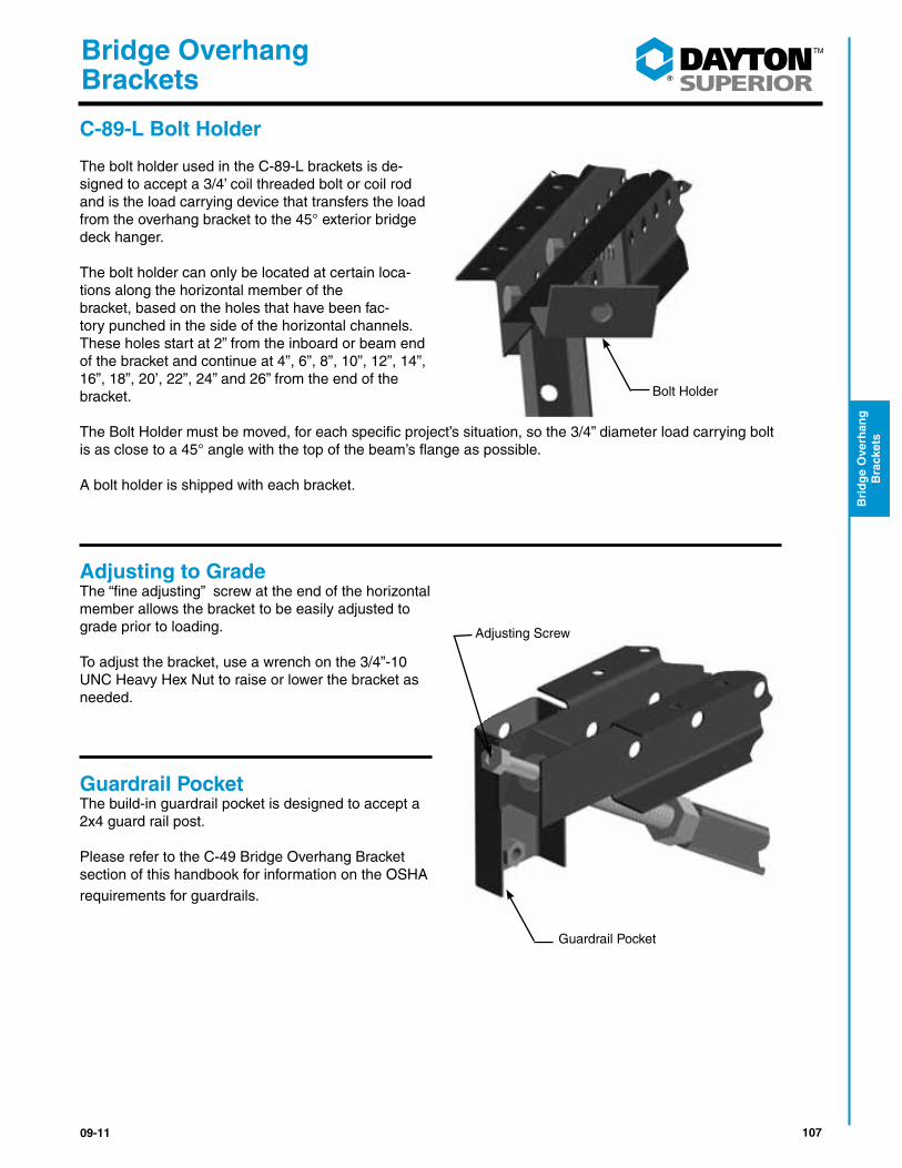
10709-11
®
Bridge Overhang Brackets
Bri
dg
e O
verh
ang
B
rack
ets
C-89-L Bolt Holder The bolt holder used in the C-89-L brackets is de-signed to accept a 3/4’ coil threaded bolt or coil rod and is the load carrying device that transfers the load from the overhang bracket to the 45° exterior bridge deck hanger.
The bolt holder can only be located at certain loca-tions along the horizontal member of the bracket, based on the holes that have been fac-tory punched in the side of the horizontal channels. These holes start at 2” from the inboard or beam end of the bracket and continue at 4”, 6”, 8”, 10”, 12”, 14”, 16”, 18”, 20’, 22”, 24” and 26” from the end of the bracket.
The Bolt Holder must be moved, for each specific project’s situation, so the 3/4” diameter load carrying bolt is as close to a 45° angle with the top of the beam’s flange as possible.
A bolt holder is shipped with each bracket.
Adjusting to GradeThe “fine adjusting” screw at the end of the horizontal member allows the bracket to be easily adjusted to grade prior to loading. To adjust the bracket, use a wrench on the 3/4”-10 UNC Heavy Hex Nut to raise or lower the bracket as needed.
Guardrail PocketThe build-in guardrail pocket is designed to accept a 2x4 guard rail post.
Please refer to the C-49 Bridge Overhang Bracket section of this handbook for information on the OSHA requirements for guardrails.
Bolt Holder
Adjusting Screw
Guardrail Pocket

108 09-11
®
Bridge Overhang Brackets
Brid
ge O
verhan
g
Brackets
C-89-L Bridge Overhang Bracket and Exterior Hanger Spacing Over 1'-0" to 3'-0" Overhangs on Steel Beams Or Girders
D
Over 1'-0" to 3'-0"Overhang
7' - 1-3/4" maximum
Design Load PSF
Maximum Overhang Thickness
Bracket "D"
Dimension
Screed Load Per Bracket = S1 Hanger SWL
Range (lbs.)
2,500 lbs.
2,250 lbs.
2,000 lbs.
1,750 lbs.
1,500 lbs.
1,250 lbs.
1,000 lbs.
0 lbs.
130 6"
30" 4'-7" 5'-5" 5'-11" 6'-4" 6'-9" 7'-2" 7'-7" 8'-0" 8000 4'-7" 5'-5" 6'-4" 7'-2" 8'-0" 8'-0" 8'-0" 8'-0" 11300
45" 5'-2" 5'-6" 5'-11" 6'-4" 6'-9" 7'-2" 7'-7" 8'-0" 8000 8'-0" 8'-0" 8'-0" 8'-0" 8'-0" 8'-0" 8'-0" 8'-0" 11300
60" 5'-2" 5'-6" 5'-11" 6'-4" 6'-9" 7'-2" 7'-7" 8'-0" 8000 8'-0" 8'-0" 8'-0" 8'-0" 8'-0" 8'-0" 8'-0" 8'-0" 11300
157 8"
30" 4'-5" 5'-0" 5'-4" 5'-9" 6'-1" 6'-6" 6'-10" 8'-0" 8000 4'-5" 5'-3" 6'-1" 6'-11" 7'-9" 8'-0" 8'-0" 8'-0" 11300
45" 4'-7" 5'-0" 5'-4" 5'-9" 6'-1" 6'-6" 6'-10" 8'-0" 8000 8'-0" 8'-0" 8'-0" 8'-0" 8'-0" 8'-0" 8'-0" 8'-0" 11300
60" 4'-7" 5'-0" 5'-4" 5'-9" 6'-1" 6'-6" 6'-10" 8'-0" 8000 8'-0" 8'-0" 8'-0" 8'-0" 8'-0" 8'-0" 8'-0" 8'-0" 11300
184 10"
30" 4'-2" 4'-6" 4'-10" 5'-3" 5'-7" 5'-11" 6'-3" 7'-7" 8000 4'-3" 5'-1" 5'-10" 6'-8" 7'-6" 8'-0" 8'-0" 8'-0" 11300
45" 4'-2" 4'-6" 4'-10" 5'-3" 5'-7" 5'-11" 6'-3" 7'-7" 8000 7'-4" 7'-8" 8'-0" 8'-0" 8'-0" 8'-0" 8'-0" 8'-0" 11300
60" 4'-2" 4'-6" 4'-10" 5'-3" 5'-7" 5'-11" 6'-3" 7'-7" 8000 7'-4" 7'-8" 8'-0" 8'-0" 8'-0" 8'-0" 8'-0" 8'-0" 11300
210 12"
30" 3'-10" 4'-2" 4'-6" 4'-9" 5'-1" 5'-5" 5'-8" 6'-11" 8000 4'-1" 4'-10" 5'-7" 6'-4" 7'-2" 7'-11" 8'-0" 8'-0" 11300
45" 3'-10" 4'-2" 4'-6" 4'-9" 5'-1" 5'-5" 5'-8" 6'-11" 8000 6'-9" 7'-0" 7'-4" 7'-8" 8'-0" 8'-0" 8'-0" 8'-0" 11300
60" 3'-10" 4'-2" 4'-6" 4'-9" 5'-1" 5'-5" 5'-8" 6'-11" 8000 6'-9" 7'-0" 7'-4" 7'-8" 8'-0" 8'-0" 8'-0" 8'-0" 11300
237 14"
30" 3'-7" 3'-10" 4'-2" 4'-5" 4'-8" 5'-0" 5'-3" 6'-5" 8000 3'-10" 4'-7" 5'-4" 6'-1" 6'-9" 7'-6" 7'-11" 8'-0" 11300
45" 3'-7" 3'-10" 4'-2" 4'-5" 4'-8" 5'-0" 5'-3" 6'-5" 8000 6'-3" 6'-6" 6'-9" 7'-1" 7'-4" 7'-8" 7'-11" 8'-0" 11300
60" 3'-7" 3'-10" 4'-2" 4'-5" 4'-8" 5'-0" 5'-3" 6'-5" 8000 6'-3" 6'-6" 6'-9" 7'-1" 7'-4" 7'-8" 7'-11" 8'-0" 11300
264 16"
30" 3'-4" 3'-7" 3'-10" 4'-1" 4'-4" 4'-8" 4'-11" 5'-11" 8000 3'-8" 4'-4" 5'-0" 5'-8" 6'-5" 7'-1" 7'-4" 8'-0" 11300
45" 3'-4" 3'-7" 3'-10" 4'-1" 4'-4" 4'-8" 4'-11" 5'-11" 8000 5'-9" 6'-0" 6'-4" 6'-7" 6'-10" 7'-1" 7'-4" 8'-0" 11300
60" 3'-4" 3'-7" 3'-10" 4'-1" 4'-4" 4'-8" 4'-11" 5'-11" 8000 5'-9" 6'-0" 6'-4" 6'-7" 6'-10" 7'-1" 7'-4" 8'-0" 11300
290 18"
30" 3'-1" 3'-4" 3'-7" 3'-10" 4'-1" 4'-4" 4'-7" 5'-7" 8000 3'-5" 4'-1" 4'-8" 5'-4" 6'-0" 6'-8" 6'-11" 7'-10" 11300
45" 3'-1" 3'-4" 3'-7" 3'-10" 4'-1" 4'-4" 4'-7" 5'-7" 8000 5'-5" 5'-8" 5'-11" 6'-2" 6'-5" 6'-8" 6'-11" 7'-10" 11300
60" 3'-1" 3'-4" 3'-7" 3'-10" 4'-1" 4'-4" 4'-7" 5'-7" 8000 5'-5" 5'-8" 5'-11" 6'-2" 6'-5" 6'-8" 6'-11" 7'-10" 11300
317 20"
30" 2'-11" 3'-1" 3'-4" 3'-7" 3'-10" 4'-1" 4'-3" 5'-3" 8000 3'-2" 3'-10" 4'-5" 5'-0" 5'-7" 6'-3" 6'-5" 7'-5" 11300
45" 2'-11" 3'-1" 3'-4" 3'-7" 3'-10" 4'-1" 4'-3" 5'-3" 8000 5'-1" 5'-3" 5'-6" 5'-9" 6'-0" 6'-3" 6'-5" 7'-5" 11300
60" 2'-11" 3'-1" 3'-4" 3'-7" 3'-10" 4'-1" 4'-3" 5'-3" 8000 5'-1" 5'-3" 5'-6" 5'-9" 6'-0" 6'-3" 6'-5" 7'-5" 11300
NOTES:1) Design load calculations for the above bracket spacings are based on a dead load of 160 pcf for the concrete and formwork, a live load of 50 psf for workers, moveable equipment and materials, plus a 75 plf vertical load applied at the outside edge of the deck overhang. A 50 psf live load is also applied to the walkway area. 2) Always check overhang form lumber to make certain it will span the selected bracket spacing. 3) For a nominal charge, Dayton Superior Technical Service Department will calculate a recommended bracket spacing when condi-tionsonyourspecificprojectvaryfromthoseshown.
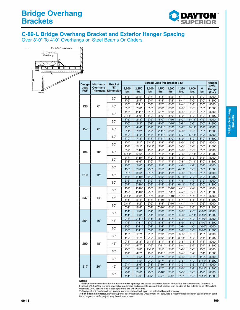
10909-11
®
Bridge Overhang Brackets
Bri
dg
e O
verh
ang
B
rack
ets
C-89-L Bridge Overhang Bracket and Exterior Hanger Spacing Over 3'-0" To 4'-0" Overhangs on Steel Beams Or Girders
D
D
3'-0" to 4'-0"Overhang
7' - 1-3/4" maximum
Design Load PSF
Maximum Overhang Thickness
Bracket "D"
Dimension
Screed Load Per Bracket = S1 Hanger SWL
Range (lbs.)
2,500 lbs.
2,250 lbs.
2,000 lbs.
1,750 lbs.
1,500 lbs.
1,250 lbs.
1,000 lbs.
0 lbs.
130 6"
30" 1'-6" 2'-5" 3'-4" 4'-3" 5'-2" 6'-1" 6'-8" 8'-0" 8000 1'-6" 2'-5" 3'-4" 4'-3" 5'-2" 6'-1" 7'-0" 8'-0" 11300
45" 4'-6" 4'-11" 5'-3" 5'-7" 6'-0" 6'-4" 6'-8" 8'-0" 8000 6'-9" 7'-8" 8'-0" 8'-0" 8'-0" 8'-0" 8'-0" 8'-0" 11300
60" 4'-6" 4'-11" 5'-3" 5'-7" 6'-0" 6'-4" 6'-8" 8'-0" 8000 7'-11" 8'-0" 8'-0" 8'-0" 8'-0" 8'-0" 8'-0" 8'-0" 11300
157 8"
30" 1'-5" 2'-3" 3'-2" 4'-0" 4'-10" 5'-7" 5'-11" 7'-2" 8000 1'-5" 2'-3" 3'-2" 4'-0" 4'-10" 5'-8" 6'-6" 8'-0" 11300
45" 4'-0" 4'-4" 4'-7" 4'-11" 5'-3" 5'-7" 5'-11" 7'-2" 8000 6'-4" 7'-2" 7'-7" 7'-11" 8'-0" 8'-0" 8'-0" 8'-0" 11300
60" 4'-0" 4'-4" 4'-7" 4'-11" 5'-3" 5'-7" 5'-11" 7'-2" 8000 7'-0" 7'-3" 7'-7" 7'-11" 8'-0" 8'-0" 8'-0" 8'-0" 11300
184 10"
30" 1'-4" 2'-1" 2'-11" 3'-8" 4'-6" 5'-0" 5'-3" 6'-5" 8000 1'-4" 2'-1" 2'-11" 3'-8" 4'-6" 5'-3" 6'-1" 8'-0" 11300
45" 3'-7" 3'-10" 4'-2" 4'-5" 4'-8" 5'-0" 5'-3" 6'-5" 8000 5'-11" 6'-6" 6'-9" 7'-1" 7'-4" 7'-8" 7'-11" 8'-0" 11300
60" 3'-7" 3'-10" 4'-2" 4'-5" 4'-8" 5'-0" 5'-3" 6'-5" 8000 6'-3" 6'-6" 6'-9" 7'-1" 7'-4" 7'-8" 7'-11" 8'-0" 11300
210 12"
30" 1'-3" 2'-0" 2'-8" 3'-5" 4'-2" 4'-6" 4'-9" 5'-9" 8000 1'-3" 2'-0" 2'-8" 3'-5" 4'-2" 4'-11" 5'-8" 8'-0" 11300
45" 3'-3" 3'-6" 3'-9" 4'-0" 4'-3" 4'-6" 4'-9" 5'-9" 8000 5'-6" 5'-10" 6'-2" 6'-5" 6'-8" 6'-11" 7'-2" 8'-0" 11300
60" 3'-3" 3'-6" 3'-9" 4'-0" 4'-3" 4'-6" 4'-9" 5'-9" 8000 5'-7" 5'-10" 6'-2" 6'-5" 6'-8" 6'-11" 7'-2" 8'-0" 11300
237 14"
30" 1'-2" 1'-10" 2'-6" 3'-2" 3'-10" 4'-1" 4'-4" 5'-3" 8000 1'-2" 1'-10" 2'-6" 3'-2" 3'-11" 4'-7" 5'-3" 7'-6" 11300
45" 2'-11" 3'-2" 3'-5" 3'-8" 3'-10" 4'-1" 4'-4" 5'-3" 8000 5'-1" 5'-4" 5'-7" 5'-10" 6'-1" 6'-4" 6'-6" 7'-6" 11300
60" 2'-11" 3'-2" 3'-5" 3'-8" 3'-10" 4'-1" 4'-4" 5'-3" 8000 5'-1" 5'-4" 5'-7" 5'-10" 6'-1" 6'-4" 6'-6" 7'-6" 11300
264 16"
30" 1'-1" 1'-8" 2'-4" 3'-0" 3'-7" 3'-9" 4'-0" 4'-10" 8000 1'-1" 1'-8" 2'-4" 3'-0" 3'-7" 4'-3" 4'-11" 6'-10" 11300
45" 2'-8" 2'-11" 3'-1" 3'-4" 3'-7" 3'-9" 4'-0" 4'-10" 8000 4'-8" 4'-11" 5'-2" 5'-4" 5'-7" 5'-9" 6'-0" 6'-10" 11300
60" 2'-8" 2'-11" 3'-1" 3'-4" 3'-7" 3'-9" 4'-0" 4'-10" 8000 4'-8" 4'-11" 5'-2" 5'-4" 5'-7" 5'-9" 6'-0" 6'-10" 11300
290 18"
30" 1'-0" 1'-7" 2'-2" 2'-9" 3'-3" 3'-6" 3'-8" 4'-6" 8000 1'-0" 1'-7" 2'-2" 2'-9" 3'-4" 3'-11" 4'-6" 6'-4" 11300
45" 2'-6" 2'-8" 2'-11" 3'-1" 3'-3" 3'-6" 3'-8" 4'-6" 8000 4'-4" 4'-7" 4'-9" 4'-11" 5'-2" 5'-4" 5'-7" 6'-4" 11300
60" 2'-6" 2'-8" 2'-11" 3'-1" 3'-3" 3'-6" 3'-8" 4'-6" 8000 4'-4" 4'-7" 4'-9" 4'-11" 5'-2" 5'-4" 5'-7" 6'-4" 11300
317 20"
30"* 1'-5" 2'-0" 2'-7" 3'-1" 3'-3" 3'-5" 4'-2" 8000 * 1'-5" 2'-0" 2'-7" 3'-1" 3'-8" 4'-2" 5'-11" 11300
45" 2'-4" 2'-6" 2'-8" 2'-10" 3'-1" 3'-3" 3'-5" 4'-2" 8000 4'-1" 4'-3" 4'-5" 4'-7" 4'-9" 5'-0" 5'-2" 5'-11" 11300
60" 2'-4" 2'-6" 2'-8" 2'-10" 3'-1" 3'-3" 3'-5" 4'-2" 8000 4'-1" 4'-3" 4'-5" 4'-7" 4'-9" 5'-0" 5'-2" 5'-11" 11300
NOTES:1) Design load calculations for the above bracket spacings are based on a dead load of 160 pcf for the concrete and formwork, a live load of 50 psf for workers, moveable equipment and materials, plus a 75 plf vertical load applied at the outside edge of the deck overhang. A 50 psf live load is also applied to the walkway area. 2) Always check overhang form lumber to make certain it will span the selected bracket spacing.3) For a nominal charge, Dayton Superior Technical Service Department will calculate a recommended bracket spacing when condi-tionsonyourspecificprojectvaryfromthoseshown.
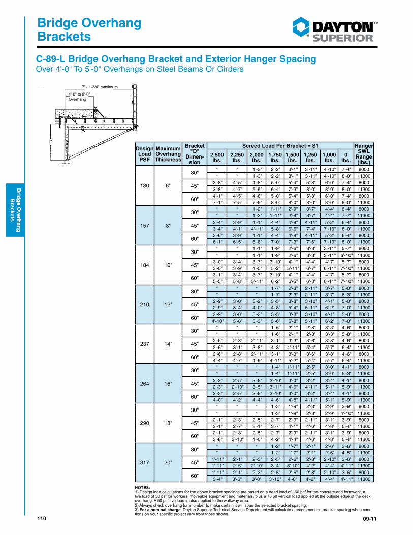
110 09-11
®
Bridge Overhang Brackets
Brid
ge O
verhan
g
Brackets
C-89-L Bridge Overhang Bracket and Exterior Hanger Spacing Over 4'-0" To 5'-0" Overhangs on Steel Beams Or Girders
D
D
4'-0" to 5'-0"Overhang
7' - 1-3/4" maximum
Design Load PSF
Maximum Overhang Thickness
Bracket "D"
Dimen-sion
Screed Load Per Bracket = S1 Hanger SWL
Range (lbs.)
2,500 lbs.
2,250 lbs.
2,000 lbs.
1,750 lbs.
1,500 lbs.
1,250 lbs.
1,000 lbs.
0 lbs.
130 6"
30"* * 1'-3" 2'-2" 3'-1" 3'-11" 4'-10" 7'-4" 8000
* * 1'-3" 2'-2" 3'-1" 3'-11" 4'-10" 8'-0" 11300
45" 3'-8" 4'-5" 4'-8" 5'-0" 5'-4" 5'-8" 6'-0" 7'-4" 8000 3'-8" 4'-7" 5'-5" 6'-4" 7'-3" 8'-0" 8'-0" 8'-0" 11300
60" 4'-1" 4'-5" 4'-8" 5'-0" 5'-4" 5'-8" 6'-0" 7'-4" 8000 7'-1" 7'-5" 7'-9" 8'-0" 8'-0" 8'-0" 8'-0" 8'-0" 11300
157 8"
30"* * 1'-2" 1'-11" 2'-9" 3'-7" 4'-4" 6'-4" 8000 * * 1'-2" 1'-11" 2'-9" 3'-7" 4'-4" 7'-7" 11300
45" 3'-4" 3'-9" 4'-1" 4'-4" 4'-8" 4'-11" 5'-2" 6'-4" 8000 3'-4" 4'-1" 4'-11" 5'-8" 6'-6" 7'-4" 7'-10" 8'-0" 11300
60" 3'-6" 3'-9" 4'-1" 4'-4" 4'-8" 4'-11" 5'-2" 6'-4" 8000 6'-1" 6'-5" 6'-8" 7'-0" 7'-3" 7'-6" 7'-10" 8'-0" 11300
184 10"
30"* * 1'-1" 1'-9" 2'-6" 3'-3" 3'-11" 5'-7" 8000 * * 1'-1" 1'-9" 2'-6" 3'-3" 3'-11" 6'-10" 11300
45" 3'-0" 3'-4" 3'-7" 3'-10" 4'-1" 4'-4" 4'-7" 5'-7" 8000 3'-0" 3'-9" 4'-5" 5'-2" 5'-11" 6'-7" 6'-11" 7'-10" 11300
60" 3'-1" 3'-4" 3'-7" 3'-10" 4'-1" 4'-4" 4'-7" 5'-7" 8000 5'-5" 5'-8" 5'-11" 6'-2" 6'-5" 6'-8" 6'-11" 7'-10" 11300
210 12"
30"* * * 1'-7" 2'-3" 2'-11" 3'-7" 5'-0" 8000 * * * 1'-7" 2'-3" 2'-11" 3'-7" 6'-3" 11300
45" 2'-9" 3'-0" 3'-2" 3'-5" 3'-8" 3'-10" 4'-1" 5'-0" 8000 2'-9" 3'-4" 4'-0" 4'-8" 5'-4" 5'-11" 6'-2" 7'-0" 11300
60" 2'-9" 3'-0" 3'-2" 3'-5" 3'-8" 3'-10" 4'-1" 5'-0" 8000 4'-10" 5'-0" 5'-3" 5'-6" 5'-8" 5'-11" 6'-2" 7'-0" 11300
237 14"
30"* * * 1'-6" 2'-1" 2'-8" 3'-3" 4'-6" 8000 * * * 1'-6" 2'-1" 2'-8" 3'-3" 5'-8" 11300
45" 2'-6" 2'-8" 2'-11" 3'-1" 3'-3" 3'-6" 3'-8" 4'-6" 8000 2'-6" 3'-1" 3'-8" 4'-3" 4'-11" 5'-4" 5'-7" 6'-4" 11300
60" 2'-6" 2'-8" 2'-11" 3'-1" 3'-3" 3'-6" 3'-8" 4'-6" 8000 4'-4" 4'-7" 4'-9" 4'-11" 5'-2" 5'-4" 5'-7" 6'-4" 11300
264 16"
30"* * * 1'-4" 1'-11" 2'-5" 3'-0" 4'-1" 8000 * * * 1'-4" 1'-11" 2'-5" 3'-0" 5'-3" 11300
45" 2'-3" 2'-5" 2'-8" 2'-10" 3'-0" 3'-2" 3'-4" 4'-1" 8000 2'-3" 2'-10" 3'-5" 3'-11" 4'-6" 4'-11" 5'-1" 5'-9" 11300
60" 2'-3" 2'-5" 2'-8" 2'-10" 3'-0" 3'-2" 3'-4" 4'-1" 8000 4'-0" 4'-2" 4'-4" 4'-6" 4'-8" 4'-11" 5'-1" 5'-9" 11300
290 18"
30"* * * 1'-3" 1'-9" 2'-3" 2'-9" 3'-9" 8000 * * * 1'-3" 1'-9" 2'-3" 2'-9" 4'-10" 11300
45" 2'-1" 2'-3" 2'-5" 2'-7" 2'-9" 2'-11" 3'-1" 3'-9" 8000 2'-1" 2'-7" 3'-1" 3'-7" 4'-1" 4'-6" 4'-8" 5'-4" 11300
60" 2'-1" 2'-3" 2'-5" 2'-7" 2'-9" 2'-11" 3'-1" 3'-9" 8000 3'-8" 3'-10" 4'-0" 4'-2" 4'-4" 4'-6" 4'-8" 5'-4" 11300
317 20"
30"* * * 1'-2" 1'-7" 2'-1" 2'-6" 3'-6" 8000 * * * 1'-2" 1'-7" 2'-1" 2'-6" 4'-5" 11300
45" 1'-11" 2'-1" 2'-3" 2'-5" 2'-6" 2'-8" 2'-10" 3'-6" 8000 1'-11" 2'-5" 2'-10" 3'-4" 3'-10" 4'-2" 4'-4" 4'-11" 11300
60" 1'-11" 2'-1" 2'-3" 2'-5" 2'-6" 2'-8" 2'-10" 3'-6" 8000 3'-4" 3'-6" 3'-8" 3'-10" 4'-0" 4'-2" 4'-4" 4'-11" 11300
NOTES:1) Design load calculations for the above bracket spacings are based on a dead load of 160 pcf for the concrete and formwork, a live load of 50 psf for workers, moveable equipment and materials, plus a 75 plf vertical load applied at the outside edge of the deck overhang. A 50 psf live load is also applied to the walkway area. 2) Always check overhang form lumber to make certain it will span the selected bracket spacing.3) For a nominal charge, Dayton Superior Technical Service Department will calculate a recommended bracket spacing when condi-tionsonyourspecificprojectvaryfromthoseshown.
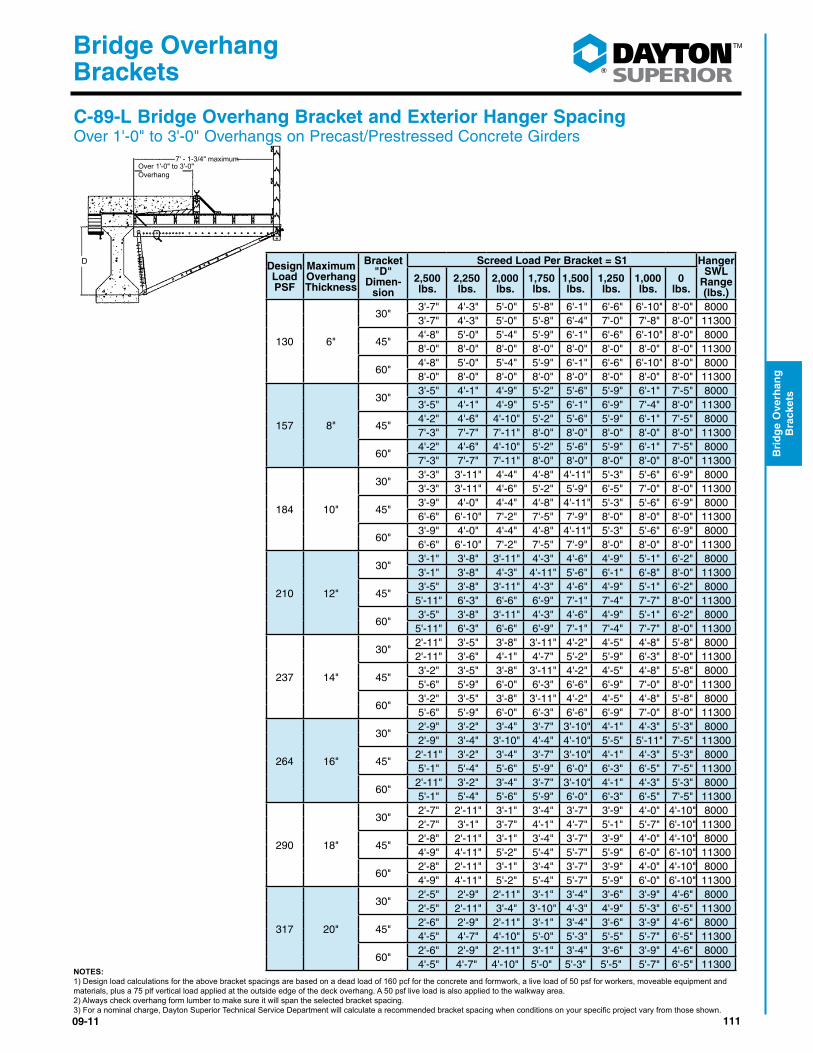
11109-11
®
Bridge Overhang Brackets
Bri
dg
e O
verh
ang
B
rack
ets
D
7' - 1-3/4" maximumOver 1'-0" to 3'-0"Overhang
C-89-L Bridge Overhang Bracket and Exterior Hanger Spacing Over 1'-0" to 3'-0" Overhangs on Precast/Prestressed Concrete Girders
Design Load PSF
Maximum Overhang Thickness
Bracket "D"
Dimen-sion
Screed Load Per Bracket = S1 Hanger SWL
Range (lbs.)
2,500 lbs.
2,250 lbs.
2,000 lbs.
1,750 lbs.
1,500 lbs.
1,250 lbs.
1,000 lbs.
0 lbs.
130 6"
30" 3'-7" 4'-3" 5'-0" 5'-8" 6'-1" 6'-6" 6'-10" 8'-0" 8000 3'-7" 4'-3" 5'-0" 5'-8" 6'-4" 7'-0" 7'-8" 8'-0" 11300
45" 4'-8" 5'-0" 5'-4" 5'-9" 6'-1" 6'-6" 6'-10" 8'-0" 8000 8'-0" 8'-0" 8'-0" 8'-0" 8'-0" 8'-0" 8'-0" 8'-0" 11300
60" 4'-8" 5'-0" 5'-4" 5'-9" 6'-1" 6'-6" 6'-10" 8'-0" 8000 8'-0" 8'-0" 8'-0" 8'-0" 8'-0" 8'-0" 8'-0" 8'-0" 11300
157 8"
30" 3'-5" 4'-1" 4'-9" 5'-2" 5'-6" 5'-9" 6'-1" 7'-5" 8000 3'-5" 4'-1" 4'-9" 5'-5" 6'-1" 6'-9" 7'-4" 8'-0" 11300
45" 4'-2" 4'-6" 4'-10" 5'-2" 5'-6" 5'-9" 6'-1" 7'-5" 8000 7'-3" 7'-7" 7'-11" 8'-0" 8'-0" 8'-0" 8'-0" 8'-0" 11300
60" 4'-2" 4'-6" 4'-10" 5'-2" 5'-6" 5'-9" 6'-1" 7'-5" 8000 7'-3" 7'-7" 7'-11" 8'-0" 8'-0" 8'-0" 8'-0" 8'-0" 11300
184 10"
30" 3'-3" 3'-11" 4'-4" 4'-8" 4'-11" 5'-3" 5'-6" 6'-9" 8000 3'-3" 3'-11" 4'-6" 5'-2" 5'-9" 6'-5" 7'-0" 8'-0" 11300
45" 3'-9" 4'-0" 4'-4" 4'-8" 4'-11" 5'-3" 5'-6" 6'-9" 8000 6'-6" 6'-10" 7'-2" 7'-5" 7'-9" 8'-0" 8'-0" 8'-0" 11300
60" 3'-9" 4'-0" 4'-4" 4'-8" 4'-11" 5'-3" 5'-6" 6'-9" 8000 6'-6" 6'-10" 7'-2" 7'-5" 7'-9" 8'-0" 8'-0" 8'-0" 11300
210 12"
30" 3'-1" 3'-8" 3'-11" 4'-3" 4'-6" 4'-9" 5'-1" 6'-2" 8000 3'-1" 3'-8" 4'-3" 4'-11" 5'-6" 6'-1" 6'-8" 8'-0" 11300
45" 3'-5" 3'-8" 3'-11" 4'-3" 4'-6" 4'-9" 5'-1" 6'-2" 8000 5'-11" 6'-3" 6'-6" 6'-9" 7'-1" 7'-4" 7'-7" 8'-0" 11300
60" 3'-5" 3'-8" 3'-11" 4'-3" 4'-6" 4'-9" 5'-1" 6'-2" 8000 5'-11" 6'-3" 6'-6" 6'-9" 7'-1" 7'-4" 7'-7" 8'-0" 11300
237 14"
30" 2'-11" 3'-5" 3'-8" 3'-11" 4'-2" 4'-5" 4'-8" 5'-8" 8000 2'-11" 3'-6" 4'-1" 4'-7" 5'-2" 5'-9" 6'-3" 8'-0" 11300
45" 3'-2" 3'-5" 3'-8" 3'-11" 4'-2" 4'-5" 4'-8" 5'-8" 8000 5'-6" 5'-9" 6'-0" 6'-3" 6'-6" 6'-9" 7'-0" 8'-0" 11300
60" 3'-2" 3'-5" 3'-8" 3'-11" 4'-2" 4'-5" 4'-8" 5'-8" 8000 5'-6" 5'-9" 6'-0" 6'-3" 6'-6" 6'-9" 7'-0" 8'-0" 11300
264 16"
30" 2'-9" 3'-2" 3'-4" 3'-7" 3'-10" 4'-1" 4'-3" 5'-3" 8000 2'-9" 3'-4" 3'-10" 4'-4" 4'-10" 5'-5" 5'-11" 7'-5" 11300
45" 2'-11" 3'-2" 3'-4" 3'-7" 3'-10" 4'-1" 4'-3" 5'-3" 8000 5'-1" 5'-4" 5'-6" 5'-9" 6'-0" 6'-3" 6'-5" 7'-5" 11300
60" 2'-11" 3'-2" 3'-4" 3'-7" 3'-10" 4'-1" 4'-3" 5'-3" 8000 5'-1" 5'-4" 5'-6" 5'-9" 6'-0" 6'-3" 6'-5" 7'-5" 11300
290 18"
30" 2'-7" 2'-11" 3'-1" 3'-4" 3'-7" 3'-9" 4'-0" 4'-10" 8000 2'-7" 3'-1" 3'-7" 4'-1" 4'-7" 5'-1" 5'-7" 6'-10" 11300
45" 2'-8" 2'-11" 3'-1" 3'-4" 3'-7" 3'-9" 4'-0" 4'-10" 8000 4'-9" 4'-11" 5'-2" 5'-4" 5'-7" 5'-9" 6'-0" 6'-10" 11300
60" 2'-8" 2'-11" 3'-1" 3'-4" 3'-7" 3'-9" 4'-0" 4'-10" 8000 4'-9" 4'-11" 5'-2" 5'-4" 5'-7" 5'-9" 6'-0" 6'-10" 11300
317 20"
30" 2'-5" 2'-9" 2'-11" 3'-1" 3'-4" 3'-6" 3'-9" 4'-6" 8000 2'-5" 2'-11" 3'-4" 3'-10" 4'-3" 4'-9" 5'-3" 6'-5" 11300
45" 2'-6" 2'-9" 2'-11" 3'-1" 3'-4" 3'-6" 3'-9" 4'-6" 8000 4'-5" 4'-7" 4'-10" 5'-0" 5'-3" 5'-5" 5'-7" 6'-5" 11300
60" 2'-6" 2'-9" 2'-11" 3'-1" 3'-4" 3'-6" 3'-9" 4'-6" 8000 4'-5" 4'-7" 4'-10" 5'-0" 5'-3" 5'-5" 5'-7" 6'-5" 11300
NOTES:1) Design load calculations for the above bracket spacings are based on a dead load of 160 pcf for the concrete and formwork, a live load of 50 psf for workers, moveable equipment and materials, plus a 75 plf vertical load applied at the outside edge of the deck overhang. A 50 psf live load is also applied to the walkway area.2) Always check overhang form lumber to make sure it will span the selected bracket spacing.3)Foranominalcharge,DaytonSuperiorTechnicalServiceDepartmentwillcalculatearecommendedbracketspacingwhenconditionsonyourspecificprojectvaryfromthoseshown.
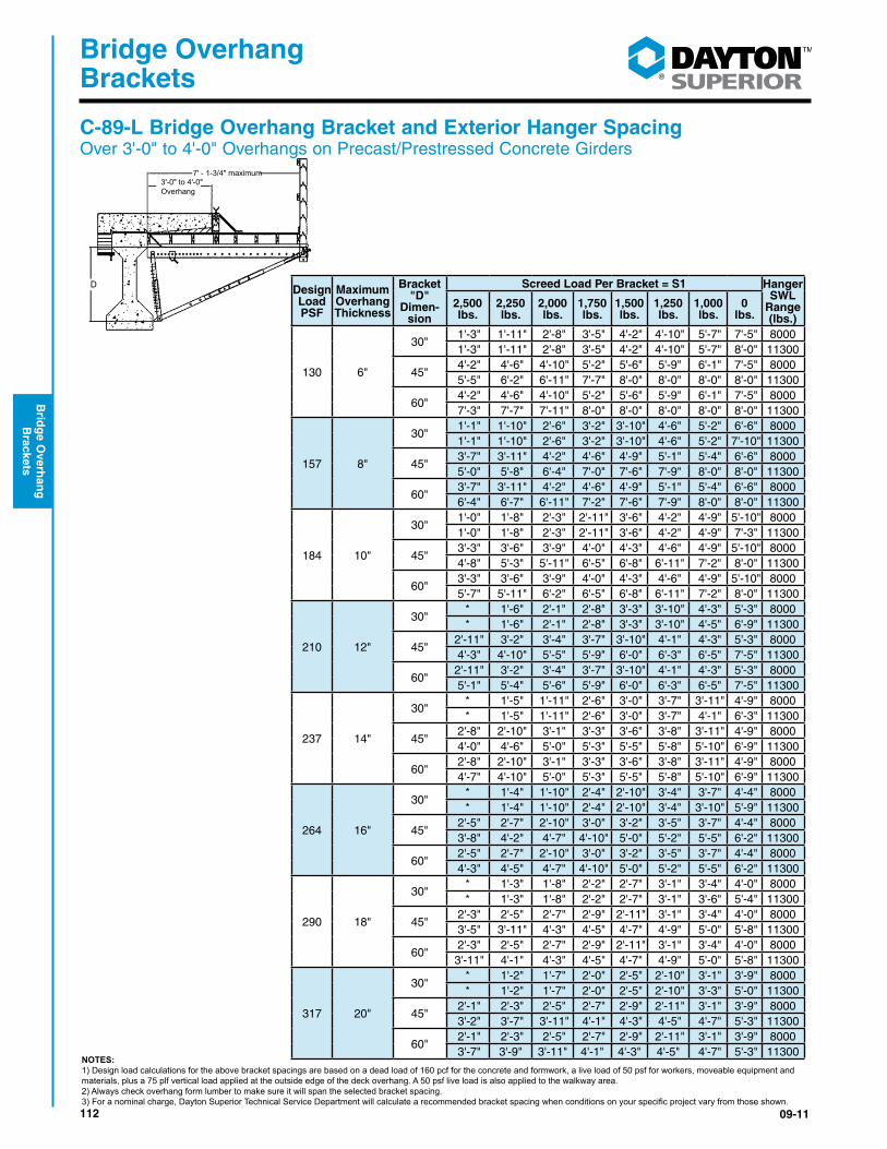
112 09-11
®
Bridge Overhang Brackets
Brid
ge O
verhan
g
Brackets
D
7' - 1-3/4" maximum3'-0" to 4'-0"Overhang
Design Load PSF
Maximum Overhang Thickness
Bracket "D"
Dimen-sion
Screed Load Per Bracket = S1 Hanger SWL
Range (lbs.)
2,500 lbs.
2,250 lbs.
2,000 lbs.
1,750 lbs.
1,500 lbs.
1,250 lbs.
1,000 lbs.
0 lbs.
130 6"
30" 1'-3" 1'-11" 2'-8" 3'-5" 4'-2" 4'-10" 5'-7" 7'-5" 8000 1'-3" 1'-11" 2'-8" 3'-5" 4'-2" 4'-10" 5'-7" 8'-0" 11300
45" 4'-2" 4'-6" 4'-10" 5'-2" 5'-6" 5'-9" 6'-1" 7'-5" 8000 5'-5" 6'-2" 6'-11" 7'-7" 8'-0" 8'-0" 8'-0" 8'-0" 11300
60" 4'-2" 4'-6" 4'-10" 5'-2" 5'-6" 5'-9" 6'-1" 7'-5" 8000 7'-3" 7'-7" 7'-11" 8'-0" 8'-0" 8'-0" 8'-0" 8'-0" 11300
157 8"
30" 1'-1" 1'-10" 2'-6" 3'-2" 3'-10" 4'-6" 5'-2" 6'-6" 8000 1'-1" 1'-10" 2'-6" 3'-2" 3'-10" 4'-6" 5'-2" 7'-10" 11300
45" 3'-7" 3'-11" 4'-2" 4'-6" 4'-9" 5'-1" 5'-4" 6'-6" 8000 5'-0" 5'-8" 6'-4" 7'-0" 7'-6" 7'-9" 8'-0" 8'-0" 11300
60" 3'-7" 3'-11" 4'-2" 4'-6" 4'-9" 5'-1" 5'-4" 6'-6" 8000 6'-4" 6'-7" 6'-11" 7'-2" 7'-6" 7'-9" 8'-0" 8'-0" 11300
184 10"
30" 1'-0" 1'-8" 2'-3" 2'-11" 3'-6" 4'-2" 4'-9" 5'-10" 8000 1'-0" 1'-8" 2'-3" 2'-11" 3'-6" 4'-2" 4'-9" 7'-3" 11300
45" 3'-3" 3'-6" 3'-9" 4'-0" 4'-3" 4'-6" 4'-9" 5'-10" 8000 4'-8" 5'-3" 5'-11" 6'-5" 6'-8" 6'-11" 7'-2" 8'-0" 11300
60" 3'-3" 3'-6" 3'-9" 4'-0" 4'-3" 4'-6" 4'-9" 5'-10" 8000 5'-7" 5'-11" 6'-2" 6'-5" 6'-8" 6'-11" 7'-2" 8'-0" 11300
210 12"
30"* 1'-6" 2'-1" 2'-8" 3'-3" 3'-10" 4'-3" 5'-3" 8000 * 1'-6" 2'-1" 2'-8" 3'-3" 3'-10" 4'-5" 6'-9" 11300
45" 2'-11" 3'-2" 3'-4" 3'-7" 3'-10" 4'-1" 4'-3" 5'-3" 8000 4'-3" 4'-10" 5'-5" 5'-9" 6'-0" 6'-3" 6'-5" 7'-5" 11300
60" 2'-11" 3'-2" 3'-4" 3'-7" 3'-10" 4'-1" 4'-3" 5'-3" 8000 5'-1" 5'-4" 5'-6" 5'-9" 6'-0" 6'-3" 6'-5" 7'-5" 11300
237 14"
30"* 1'-5" 1'-11" 2'-6" 3'-0" 3'-7" 3'-11" 4'-9" 8000 * 1'-5" 1'-11" 2'-6" 3'-0" 3'-7" 4'-1" 6'-3" 11300
45" 2'-8" 2'-10" 3'-1" 3'-3" 3'-6" 3'-8" 3'-11" 4'-9" 8000 4'-0" 4'-6" 5'-0" 5'-3" 5'-5" 5'-8" 5'-10" 6'-9" 11300
60" 2'-8" 2'-10" 3'-1" 3'-3" 3'-6" 3'-8" 3'-11" 4'-9" 8000 4'-7" 4'-10" 5'-0" 5'-3" 5'-5" 5'-8" 5'-10" 6'-9" 11300
264 16"
30"* 1'-4" 1'-10" 2'-4" 2'-10" 3'-4" 3'-7" 4'-4" 8000 * 1'-4" 1'-10" 2'-4" 2'-10" 3'-4" 3'-10" 5'-9" 11300
45" 2'-5" 2'-7" 2'-10" 3'-0" 3'-2" 3'-5" 3'-7" 4'-4" 8000 3'-8" 4'-2" 4'-7" 4'-10" 5'-0" 5'-2" 5'-5" 6'-2" 11300
60" 2'-5" 2'-7" 2'-10" 3'-0" 3'-2" 3'-5" 3'-7" 4'-4" 8000 4'-3" 4'-5" 4'-7" 4'-10" 5'-0" 5'-2" 5'-5" 6'-2" 11300
290 18"
30"* 1'-3" 1'-8" 2'-2" 2'-7" 3'-1" 3'-4" 4'-0" 8000 * 1'-3" 1'-8" 2'-2" 2'-7" 3'-1" 3'-6" 5'-4" 11300
45" 2'-3" 2'-5" 2'-7" 2'-9" 2'-11" 3'-1" 3'-4" 4'-0" 8000 3'-5" 3'-11" 4'-3" 4'-5" 4'-7" 4'-9" 5'-0" 5'-8" 11300
60" 2'-3" 2'-5" 2'-7" 2'-9" 2'-11" 3'-1" 3'-4" 4'-0" 8000 3'-11" 4'-1" 4'-3" 4'-5" 4'-7" 4'-9" 5'-0" 5'-8" 11300
317 20"
30"* 1'-2" 1'-7" 2'-0" 2'-5" 2'-10" 3'-1" 3'-9" 8000 * 1'-2" 1'-7" 2'-0" 2'-5" 2'-10" 3'-3" 5'-0" 11300
45" 2'-1" 2'-3" 2'-5" 2'-7" 2'-9" 2'-11" 3'-1" 3'-9" 8000 3'-2" 3'-7" 3'-11" 4'-1" 4'-3" 4'-5" 4'-7" 5'-3" 11300
60" 2'-1" 2'-3" 2'-5" 2'-7" 2'-9" 2'-11" 3'-1" 3'-9" 8000 3'-7" 3'-9" 3'-11" 4'-1" 4'-3" 4'-5" 4'-7" 5'-3" 11300
NOTES:1) Design load calculations for the above bracket spacings are based on a dead load of 160 pcf for the concrete and formwork, a live load of 50 psf for workers, moveable equipment and materials, plus a 75 plf vertical load applied at the outside edge of the deck overhang. A 50 psf live load is also applied to the walkway area.2) Always check overhang form lumber to make sure it will span the selected bracket spacing.3)Foranominalcharge,DaytonSuperiorTechnicalServiceDepartmentwillcalculatearecommendedbracketspacingwhenconditionsonyourspecificprojectvaryfromthoseshown.
C-89-L Bridge Overhang Bracket and Exterior Hanger Spacing Over 3'-0" to 4'-0" Overhangs on Precast/Prestressed Concrete Girders

11309-11
®
Bridge Overhang Brackets
Bri
dg
e O
verh
ang
B
rack
ets
D
7' - 1-3/4" maximum4'-0" to 5'-0"Overhang
Design Load PSF
Maximum Overhang Thickness
Bracket "D"
Dimen-sion
Screed Load Per Bracket = S1 Hanger SWL
Range (lbs.)
2,500 lbs.
2,250 lbs.
2,000 lbs.
1,750 lbs.
1,500 lbs.
1,250 lbs.
1,000 lbs.
0 lbs.
130 6"
30"* * 1'-1" 1'-9" 2'-6" 3'-3" 3'-11" 6'-8" 8000 * * 1'-1" 1'-9" 2'-6" 3'-3" 3'-11" 6'-10" 11300
45" 3'-0" 3'-8" 4'-4" 4'-8" 4'-11" 5'-3" 5'-6" 6'-9" 8000 3'-0" 3'-8" 4'-5" 5'-2" 5'-11" 6'-7" 7'-4" 8'-0" 11300
60" 3'-9" 4'-0" 4'-4" 4'-8" 4'-11" 5'-3" 5'-6" 6'-9" 8000 5'-10" 6'-6" 7'-2" 7'-5" 7'-9" 8'-0" 8'-0" 8'-0" 11300
157 8"
30"* * * 1'-7" 2'-3" 2'-11" 3'-6" 5'-10" 8000 * * * 1'-7" 2'-3" 2'-11" 3'-6" 6'-1" 11300
45" 2'-8" 3'-4" 3'-9" 4'-0" 4'-3" 4'-6" 4'-9" 5'-10" 8000 2'-8" 3'-4" 4'-0" 4'-7" 5'-3" 5'-11" 6'-7" 8'-0" 11300
60" 3'-3" 3'-6" 3'-9" 4'-0" 4'-3" 4'-6" 4'-9" 5'-10" 8000 5'-2" 5'-10" 6'-2" 6'-5" 6'-8" 6'-11" 7'-2" 8'-0" 11300
184 10"
30"* * * 1'-5" 2'-0" 2'-7" 3'-2" 5'-1" 8000 * * * 1'-5" 2'-0" 2'-7" 3'-2" 5'-6" 11300
45" 2'-5" 3'-0" 3'-3" 3'-6" 3'-9" 3'-11" 4'-2" 5'-1" 8000 2'-5" 3'-0" 3'-7" 4'-2" 4'-9" 5'-4" 5'-11" 7'-2" 11300
60" 2'-10" 3'-1" 3'-3" 3'-6" 3'-9" 3'-11" 4'-2" 5'-1" 8000 4'-8" 5'-2" 5'-5" 5'-7" 5'-10" 6'-1" 6'-4" 7'-2" 11300
210 12"
30"* * * 1'-3" 1'-10" 2'-4" 2'-11" 4'-6" 8000 * * * 1'-3" 1'-10" 2'-4" 2'-11" 5'-0" 11300
45" 2'-2" 2'-9" 2'-11" 3'-1" 3'-4" 3'-6" 3'-9" 4'-6" 8000 2'-2" 2'-9" 3'-3" 3'-9" 4'-4" 4'-10" 5'-4" 6'-5" 11300
60" 2'-6" 2'-9" 2'-11" 3'-1" 3'-4" 3'-6" 3'-9" 4'-6" 8000 4'-3" 4'-7" 4'-10" 5'-0" 5'-3" 5'-5" 5'-7" 6'-5" 11300
237 14"
30"* * * 1'-2" 1'-8" 2'-2" 2'-8" 4'-1" 8000 * * * 1'-2" 1'-8" 2'-2" 2'-8" 4'-7" 11300
45" 2'-0" 2'-5" 2'-8" 2'-10" 3'-0" 3'-2" 3'-4" 4'-1" 8000 2'-0" 2'-6" 2'-11" 3'-5" 3'-11" 4'-5" 4'-11" 5'-10" 11300
60" 2'-3" 2'-5" 2'-8" 2'-10" 3'-0" 3'-2" 3'-4" 4'-1" 8000 3'-10" 4'-2" 4'-4" 4'-6" 4'-8" 4'-11" 5'-1" 5'-10" 11300
264 16"
30"* * * 1'-1" 1'-6" 2'-0" 2'-5" 3'-9" 8000 * * * 1'-1" 1'-6" 2'-0" 2'-5" 4'-2" 11300
45" 1'-10" 2'-3" 2'-5" 2'-7" 2'-9" 2'-11" 3'-1" 3'-9" 8000 1'-10" 2'-3" 2'-8" 3'-2" 3'-7" 4'-0" 4'-6" 5'-3" 11300
60" 2'-1" 2'-3" 2'-5" 2'-7" 2'-9" 2'-11" 3'-1" 3'-9" 8000 3'-6" 3'-9" 3'-11" 4'-1" 4'-3" 4'-5" 4'-7" 5'-3" 11300
290 18"
30"* * * 1'-0" 1'-5" 1'-10" 2'-3" 3'-5" 8000 * * * 1'-0" 1'-5" 1'-10" 2'-3" 3'-10" 11300
45" 1'-8" 2'-0" 2'-2" 2'-4" 2'-6" 2'-8" 2'-10" 3'-5" 8000 1'-8" 2'-1" 2'-6" 2'-11" 3'-4" 3'-9" 4'-2" 4'-10" 11300
60" 1'-11" 2'-0" 2'-2" 2'-4" 2'-6" 2'-8" 2'-10" 3'-5" 8000 3'-3" 3'-6" 3'-7" 3'-9" 3'-11" 4'-1" 4'-3" 4'-10" 11300
317 20"
30"* * * * 1'-3" 1'-8" 2'-0" 3'-1" 8000 * * * * 1'-3" 1'-8" 2'-0" 3'-7" 11300
45" 1'-6" 1'-11" 2'-0" 2'-2" 2'-4" 2'-5" 2'-7" 3'-2" 8000 1'-6" 1'-11" 2'-4" 2'-8" 3'-1" 3'-5" 3'-10" 4'-6" 11300
60" 1'-9" 1'-11" 2'-0" 2'-2" 2'-4" 2'-5" 2'-7" 3'-2" 8000 3'-0" 3'-2" 3'-4" 3'-6" 3'-8" 3'-9" 3'-11" 4'-6" 11300
NOTES:1) Design load calculations for the above bracket spacings are based on a dead load of 160 pcf for the concrete and formwork, a live load of 50 psf for workers, moveable equipment and materials, plus a 75 plf vertical load applied at the outside edge of the deck overhang. A 50 psf live load is also applied to the walkway area.2) Always check overhang form lumber to make sure it will span the selected bracket spacing.3)Foranominalcharge,DaytonSuperiorTechnicalServiceDepartmentwillcalculatearecommendedbracketspacingwhenconditionsonyourspecificprojectvaryfromthoseshown.
C-89-L Bridge Overhang Bracket and Exterior Hanger Spacing Over 4'-0" to 5'-0" Overhangs on Precast/Prestressed Concrete Girders