Bridge Design Standards for Roads & Highways Department
14
Government of the People’s Republic of Bangladesh Ministry of Communications Roads and Railways Division Bridge Design Standards for Roads & Highways Department January 2004
Transcript of Bridge Design Standards for Roads & Highways Department

Government of the People’s Republic of Bangladesh Ministry of Communications
Roads and Railways Division
Bridge Design Standards for
Roads & Highways Department
January 2004
Roads and Highways Department Bridge Design Standards
Foreword
In order to ensure that all roads and bridges under the Roads and Highways Department (RHD) are designed and built to appropriate high standards a series of RHD design standards and guides are being developed. This Bridge Design Standards, which has been prepared by the Bridge Management Wing of RHD, forms part of that series. A major innovation in this Standard is the requirement to take into account heavier live loading and inclusion of non-motorised vehicles and pedestrians on RHD bridges. To allow for future road development the minimum carriageway width over structure shall be 7.3m except where the Chief Engineer agrees an exception. The Standards are mandatory for the Bridge and Culvert designs carried out by or on behalf of Roads and Highways Department. Reconstruction of bridges is also to be undertaken in accordance with these standards. These Standards cover the large majority of situations which will be encountered in the design of RHD Bridges. However if conditions which are not covered by the Standards are encountered, the advice of the Bridge Design Circle must be obtained. I wish to thank all involved in the preparation of this important document and particularly the guidance given by Mr. Abed Uddin Ahmed, Additional Chief Engineer, Bridge Management Wing and Mr. Md. Serajul Isalm , SE, Bridge Design Circle. This document will go a long way in ensuring consistent, high quality and safe bridge designs are applied on all RHD bridges in Bangladesh.

Roads and Highways Department Bridge Design Standards
Page i
Table of Contents
1 INTRODUCTION...................................................................................................1
2 SCOPE OF WORK.................................................................................................1
3 DESIGN REFERENCES.........................................................................................1
4 LOADING CRITERIA............................................................................................2 4.1 GENERAL .......................................................................................................... 2 4.2 DEAD LOADING................................................................................................. 2 4.3 LIVE LOADING .................................................................................................. 2 4.4 ENVIRONMENTAL LOADING................................................................................ 2
4.4.1 WInd Loading.............................................................................................2 4.4.2 Temperature effects ....................................................................................2 4.4.3 Seismic Loading .........................................................................................2
5 GEOMETRICAL CRITERIA.................................................................................2 5.1 STANDARD BRIDGE CROSS-SECTIONS ................................................................. 2 5.2 LONGITUDINAL GRADIENT ................................................................................. 2 5.3 DECK CROSSFALL .............................................................................................. 3 5.4 VERTICAL CLEARANCE OVER ROADWAYS........................................................... 3 5.5 NAVIGATIONAL CLEARANCE...................................................................... 3 5.6 VERTICAL AND HORIZONTAL CLEARANCES OVER RAILWAY LINES......................... 3
6 OTHER DESIGN CRITERIA.................................................................................3 6.1 UTILITIES........................................................................................................ 3 6.2 SAFETY ASPECTS.......................................................................................... 3 6.3 DESIGN METHOD........................................................................................... 3 6.4 BRIDGE RAILINGS (PARAPETS) ................................................................... 4
Appendix 1 Bridge Standards Committee Appendix 2 Standard Bridge Cross-Sections Appendix 3 Additional Design Guidelines

Roads and Highways Department Bridge Design Standards
Page 1
1 INTRODUCTION Roads & Highways Department follows the 16th Edition of Standard Specification for Highway Bridges published by AASHTO (1996) in designing of bridges and culverts. In December 1999, under the Bridge Improvement & Maintenance Project (BIMP-2), the RHD Bridge Designers' Handbook was prepared in compliance with AASHTO. However, at present there are no uniform Standards encompassing all physical and design features of bridges/culverts so that conformity in all respects can be achieved for bridges designed and constructed by RHD. Therefore these particular RHD Bridge Design Standards (i.e. Design Criteria) have been developed. It should be noted that these Bridge Design Standards must be used in conjunction with the AASHTO Standard Specifications and are mandatory for design of all RHD bridges/culverts. 2 SCOPE OF WORK In order to carry out this task the RHD Management Team formed a Bridge Standards Committee for formulating and working out RHD Bridge Design Standards (see Appendix 1). The Committee has been assisted by the DFID-funded IDC3 (Institutional Development Component) under the Third Road Rehabilitation and Maintenance Project and DFID Bridge Replacement Project (BRP). The objective of this committee was to prepare standard design criteria for designing RHD bridges so that all bridges under this department are designed to a unified standard in all respects. These criteria include design loadings and geometric requirements. They are to be used in conjunction with the AASHTO Standard Specifications for Highway Bridges, as well as the RHD Bridge Designers’ Handbook. In addition to standard design criteria additional design guidelines are also provided to supplement the RHD Bridge Designers’ Handbook (see Appendix 3). These may be incorporated in the Handbook when it is next revised. AASHTO is intended to apply to design of small to medium span bridges (500ft pr less). Supplemental specifications may be required for unusual bridge types or for longer spans. 3 DESIGN REFERENCES For the purpose of assisting the bridge designers in the design of highway bridges for Bangladesh the following documents are to be referred to: • AASHTO Standard Specification for Highway Bridge Design (17th Edition) with its
interim specification and correction of errors applicable at the time of the design or AASHTO LRFD Bridge Design Specifications, 2nd Edition (SI Units) - 1998 with its interim specification and correction of errors applicable at the time of design.
• Indian Road Congress (IRC) interim specification and correction of errors applicable at the time of the design and not more than 9 (nine) months prior to start of works.
• RHD Bridge Designers’ Handbook (2nd Edition, 1999) • Geometric Design Standards of RHD (2001)
Roads and Highways Department Bridge Design Standards
Page 2
• Technical Specifications, Volume 3 (2001) • Standard Test Procedures (2001) 4 LOADING CRITERIA 4.1 GENERAL
Design loadings and load combinations shall be in accordance with the AASHTO and IRC Standard Specifications unless stated otherwise or amended by this document. 4.2 DEAD LOADING
The design should allow for a total surfacing thickness of 150 mm, including future surfacing overlay. Appropriate allowance should be made for stresses induced by differential settlement if such settlement is anticipated. 4.3 LIVE LOADING
Separate designs shall be prepared for live loads fully in accordance with AASHTO and for live loads fully in accordance with IRC Class A. The design adopted shall fully satisfy both types of loading. 4.4 ENVIRONMENTAL LOADING
4.4.1 WIND LOADING
The design wind velocity shall be as per latest Bangladesh National Building Code (BNBC) 1993, Chapter 2, Part 6 ‘Structural Design’. 4.4.2 TEMPERATURE EFFECTS
Temperature effects shall be considered in accordance with the provisions of the AASHTO Standard Specifications. 4.4.3 SEISMIC LOADING
Seismic design shall be carried out in accordance with Division I-A of the AASHTO Standard Specifications using appropriate national coefficients from BNBC Chapter 2, Part 6 ‘Structural Design’. 5 GEOMETRICAL CRITERIA 5.1 STANDARD BRIDGE CROSS-SECTIONS
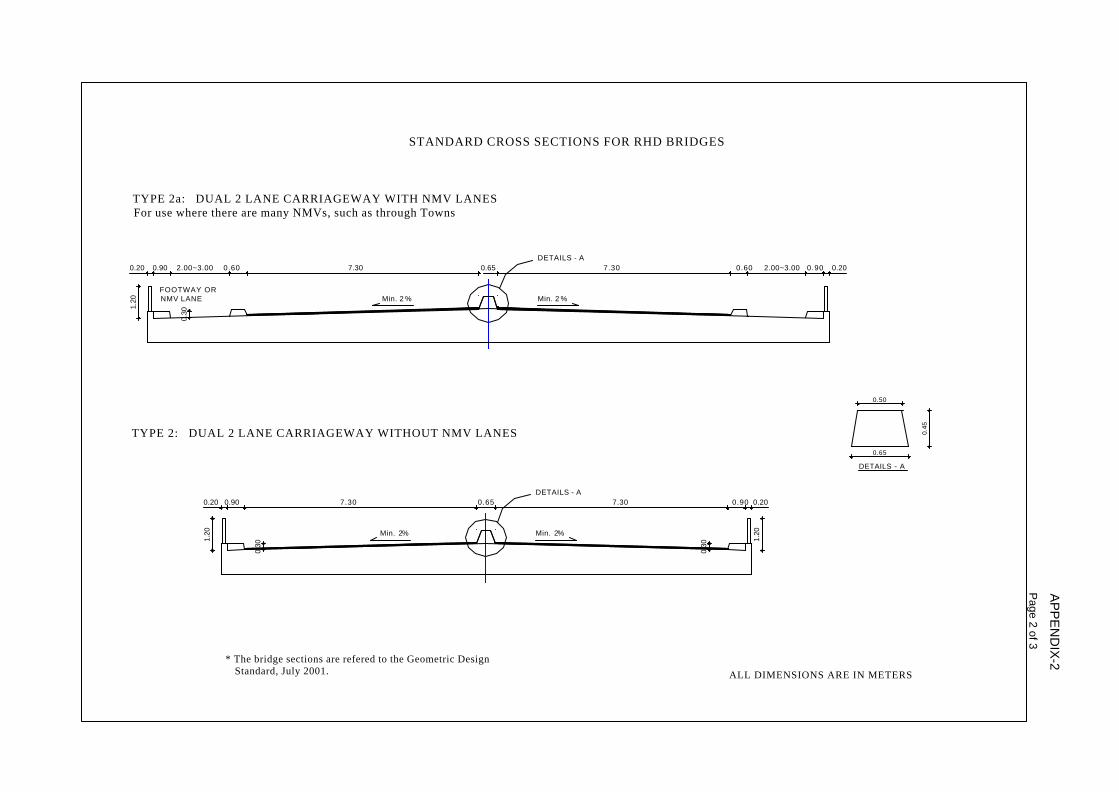
Based upon the approved Geometric Design Standards, July 2001, some typical bridge cross sections have been designed. Refer to Appendix 2. Cross-section design type and the requirement for separate NMV lanes should be determined in accordance with the recommendations of the Geometric Design Standards. Other cross-sections are only permissible in exceptional circumstances and with the written approval of the Chief Engineer. 5.2 LONGITUDINAL GRADIENT
The maximum straight gradient of structures and their approaches shall not exceed 4%. Where non motorised vehicles are likely to use the structure more appropriate

Roads and Highways Department Bridge Design Standards
Page 3
lower gradients should be utilised but may need to be a balance against cost and other environmental issues. 5.3 DECK CROSSFALL
A minimum 2% cross slope shall be provided. 5.4 VERTICAL CLEARANCE OVER ROADWAYS
For overbridges, viaducts and flyovers, vertical clearance shall be at least 5.10m over the entire carriageway, this takes into account future resurfacing. 5.5 NAVIGATIONAL CLEARANCE
The Navigational Clearance shall be in accordance with the current BIWTA requirements. Therefore the latest situation i.e. any possible change in regulation needs to be verified with BIWTA. The table below has been given for information purposes only and gives the present minimum vertical and horizontal navigation clearance as per BIWTA: Seq. Nr.
Classification of waterways
Minimum vertical Clearance (m)
Minimum horizontal clearance (m)
1. Class-I 18.30 76.22 2. Class-II 12.20 76.22 3. Class-III 7.62 30.48 4. Class-IV 5.00 20.00 For waterways which have not been classified by BIWTA, consideration shall be given to the local requirement for passage of fishing vessel, boats, trawlers, barges etc. At least one span must be kept wide enough to accommodate intended river traffic. The vertical clearance should be measured from the Standard High Water Level. The absolute minimum vertical clearance should be 1.50 m above Standard High Water Level, where boat traffic exists. 5.6 VERTICAL AND HORIZONTAL CLEARANCES OVER RAILWAY LINES
The clearances required by the Bangladesh Railway Authority shall be used. 6 OTHER DESIGN CRITERIA 6.1 UTILITIES
Bridges should be designed with provision for any potential utility services including, gas, water or sanitary pipes, cabling for electricity and telephone or other cable networks. 6.2 SAFETY ASPECTS
Design shall be in accordance with the principles set out in Section 10 of the RHD Bridge Designers’ Handbook. 6.3 DESIGN METHOD
The recommendations set out in ‘Foreword – Design Principles’ of the RHD Bridge Designers’ Handbook are to be followed.

Roads and Highways Department Bridge Design Standards
Page 4
6.4 BRIDGE RAILINGS (PARAPETS)
The recommendations set out in Section 10.3.3 - Parapets of the RHD Bridge Designers’ Handbook are to be followed. Standard designs for RCC parapets and for steel parapets shall be in accordance with Figures 10.3 and 10.4 in the same Section.

Roads and Highways Department APPENDIX 1 Bridge Design Standards
Appendix 1 Page 1
BRIDGE STANDARDS COMMITTEE The Bridge Standards Committee responsible for drafting this document consists of the following members: • Md. Serajul Islam, Superintending Engineer, RHD, Bridge Design Circle, East, Sarak
Bhaban, Ramna, Dhaka as Convenor • Md. Dalil Uddin, Executive Engineer, RHD, Bridge Division-II, East, Sarak Bhaban,
Ramna, Dhaka as Member • Md. Afil Uddin, Executive Engineer, RHD, Bridge Periodic Maintenance Division,
Sarak Bhaban, Ramna, Dhaka as member • Md. Asraful Islam, Executive Engineer, RHD, Bridge Design Division-II, West, Sarak
Bhaban, Ramna, Dhaka was co-opted as member On top of this required assistance has been taken from IDC3 (Institutional Development Component) and other RHD projects related to bridges.

Details - A
0.50
ROADS & HIGHWAYS DEPARTMENTSTANDARD CROSS SECTIONS FOR RHD BRIDGES
0.65
* The bridge sections are refered to the Geometric Design Standard, July 2001.
0.30
2.00~3.00
FOOTWAY OR NMV LANE
TYPE 1: DUAL 3 LANE CARRIAGEWAY WITH NMV LANESType 1 roads must always have NMV lanes
1.20
0.900.20 0.60 11.00
3 LANEMin. 2%
0.45
ALL DIMENSIONS ARE IN METERS
AP
PE
ND
IX-2
Page 1 of 3
2.00~3.000.6011.00
DETAILS - A
Min. 2%
0.200.90
0.65 0.90 0.20
1.20
0.900.20
1.20
ALL DIMENSIONS ARE IN METERS
* The bridge sections are refered to the Geometric Design Standard, July 2001.
0.30
Min. 2% Min. 2%
0.30
0.90 0.200.65 2.00~3.000.600.20 0.90
1.20
2.00~3.00
FOOTWAY OR NMV LANE
0.60
TYPE 2: DUAL 2 LANE CARRIAGEWAY WITHOUT NMV LANES
7.30
0.30
Min. 2 %
7.30DETAILS - A
Min. 2 %
STANDARD CROSS SECTIONS FOR RHD BRIDGES
7.30
TYPE 2a: DUAL 2 LANE CARRIAGEWAY WITH NMV LANESFor use where there are many NMVs, such as through Towns
7.30DETAILS - A
0.45
0.50
DETAILS - A
0.65
AP
PE
ND
IX-2
Page 2 of 3

0.20
1.50~3.00
TYPE 3a: 7.30m CARRIAGEWAY WITH NMV LANESFor use where there are many NMVs, such as through Towns
TYPE 3: 7.30m CARRIAGEWAY WITHOUT NMV LANE
Note : RHD has a policy to design new bridges for a minimum of two lanes on all roads including feeder roads. Therefore, no bridge cross section have been given for Type 5 and 6.
* The bridge sections are refered to the Geometric Design Standard, July 2001.
0.20 0.90
1.20
1.20
0.30
FOOTWAY AND NMV LANE
1.50~3.000.60 0.200.900.60
0.90 0.20
1.20
0.90
0.30
Min. 2% Min. 2%
ALL DIMENSIONS ARE IN METERS
AP
PE
ND
IX-2
Page 3 of 3
0.30
7.30
Min. 2% Min. 2%
1.20
7.30
STANDARD CROSS SECTIONS FOR RHD BRIDGES

Roads and Highways Department APPENDIX 3 Bridge Design Standards Page of 3
Appendix 3 Page 1
1
ADDITIONAL DESIGN GUIDELINES 1 GENERAL INFORMATION
The following general information is required in order to achieve the uniform understanding necessary to carry out bridge design.
1.1 INDEX MAP
An index map is necessary to show the suggested location of the actual bridge and alternative sites, if any. Information such as existing communication facilities, general topography of the area and existence of any significant town or market in the vicinity should also be included. 1.2 SITE PLAN
A site plan that indicates the proposed bridge location must be produced in the following form: 1. The area covered should not be less than 100 m, preferably 175 m, upstream and
downstream from the centreline of the proposed site. 2. In respect of major bridges the approaches should be shown 500 m on either side.
For smaller structures the approaches should be shown 300m on either side. 3. If meandering exists in the vicinity of the proposed bridge site, at least one meander
upstream and one meander downstream should be shown. The following information and details should be given in the site plan: 1. The name of the stream / river and the road name along with road category. 2. The outlines of the banks ; the highest flood or tide level; lowest water level; contours
at suitable places and intervals in the bed and beyond the banks; and the line of the deepest point on the riverbed. All concerned measurements and distances should be clearly defined.
3. The angle and direction of the skew if the crossing is aligned on the skew. 4. The direction of the flow of the steam. 5. Reference of Bench Mark used as datum. 6. The lines and section marks of the cross-sections with distance and longitudinal
sections within the site plan at significant points. 7. The location of proposed borings with identification number and distance. 8. The name and category of existing crossing road(s), if any, falling within the graded
approach slope of the bridge.
Roads and Highways Department APPENDIX 3 Bridge Design Standards Page of 3
Appendix 3 Page 2
2
9. The extent of the existing RHD right-of-way and the location of existing utilities and services.
1.3 HYDROLOGICAL SURVEY
Where a defined stream channel exists, cross-sections of the river shall be taken at the proposed bridge site. A minimum of eleven cross-sections should be taken through the channel (five upstream, five downstream and one on or adjacent to the proposed bridge centreline). The cross-sections should be taken at 10m intervals (i.e. to a minimum distance of 50m to either side of the new bridge), with depths measured at a minimum of ten locations for each cross-section. Additional cross-sections should be taken if necessary to establish the dimensions of the natural stable channel. 1.4 HYDROLOGICAL DATA
Hydraulic studies of bridge sites are of great importance and form an essential part of the preliminary design process. The following hydrological data is required: 1. Frequency of highest flood 2. The maximum discharge and the average flow velocity at the site 3. The estimated depth of scour; if any scour has been observed, the depth of the scour
with details of obstructions or other factors causing the scour 4. The size of the catchments 5. The shape of the catchments 6. The intensity of rainfall 7. The nature of the catchments, i.e. whether urban, under cultivation or under forest 8. The minimum navigation clearance 9. Any debris or big trees moving down-stream in the normal or high flood. 1.5 CHOICE OF SOIL PARAMETERS
Bangladeshi soil conditions have been taken into account in the RHD Bridge Designers’ Handbook (Section 2.9.2) and those recommendations are to be followed. 2 STRUCTURAL DESIGN AND DETAILING
2.1 SPLICING OF STEEL REINFORCEMENT
Splicing at points of maximum stress shall be avoided. Staggered splicing is to be used.
Roads and Highways Department APPENDIX 3 Bridge Design Standards Page of 3
Appendix 3 Page 3
3
2.2 DECK SLAB
The minimum deck slab thickness shall be 200mm. Apart from this, the recommendations set out in Section 5B ‘RC Beam and Slab Decks’ of the RHD Bridge Designers’ Handbook are to be followed. 2.3 PILING
• All piling works must to be done in accordance with RHD’s Technical Specifications, Volume 3, May 2001
• Load tests should be performed under each foundation and the test results should be sent to the respective RHD Bridge Design Circle, Sarak Bhaban, Ramna, Dhaka.
• For precast piles the pile head concrete should be broken after driving and the exposed reinforcement embedded into the pile cap.
• The tops of piles shall project not less than 150 mm into the concrete after all damaged pile material has been removed.
• For square sectioned piles the corners shall be chamfered minimum 25 mm. 2.4 ABUTMENTS AND WING WALLS
• Abutments, wing walls and supports of approach slabs (if any) are to be backfilled with 1"-6" (min) thick broken brickbats mixed with course sand. The filling should be done after installation of the bridge deck.
• Weep holes with 2" (51 mm) diameter PVC pipe are to be provided at centres of 6'-0"
(2m) horizontally and 3'-0" (1m) vertically and shall be staggered. The first row should be 1'-3" (0.4m) above the base slab.