Bridge Design Requirements - … · HS2 Bridge Design Requirements HS2-HS2-BR-STD-000-000004 2...
105
HS2-HS2-BR-STD-000-000004 |P03 | 08 April 2016 Bridge Design Requirements Revision Date Issued for/Revision details Revised by P01 01/07/2015 Initial Issue Ewan Jones P02 04/12/2015 Retitled and coordinated with other docs. Ewan Jones P03 08/04/2015 Retitled and minor update Ewan Jones Name Data FOI / EIR None Document type Standard Directorate Technical MPL & Deliverables Ref Keywords Architecture, Aesthetics, Specification, Civil Engineering Authors Oliver Moen Checker Ewan Jones Approver Andy Tye Owner C227 Atkins Review Directorate Technical, Built Environment Employer’s Lead Reviewer Tomas Garcia Authorised for use
Transcript of Bridge Design Requirements - … · HS2 Bridge Design Requirements HS2-HS2-BR-STD-000-000004 2...
HS2-HS2-BR-STD-000-000004 |P03 | 08 April 2016
Bridge Design Requirements
Revision Date Issued for/Revision details Revised by
P01 01/07/2015 Initial Issue Ewan Jones
P02 04/12/2015 Retitled and coordinated with
other docs. Ewan Jones
P03 08/04/2015 Retitled and minor update Ewan Jones
Name Data
FOI / EIR None
Document type Standard
Directorate Technical
MPL & Deliverables Ref
Keywords Architecture, Aesthetics, Specification, Civil Engineering
Authors Oliver Moen
Checker Ewan Jones
Approver Andy Tye
Owner C227 Atkins
Review Directorate Technical, Built Environment
Employer’s Lead Reviewer Tomas Garcia
Authorised for use
HS2 | Bridge Design Requirements
HS2-HS2-BR-STD-000-000004 1 Revision P05 : April 2016
HighSpeed2
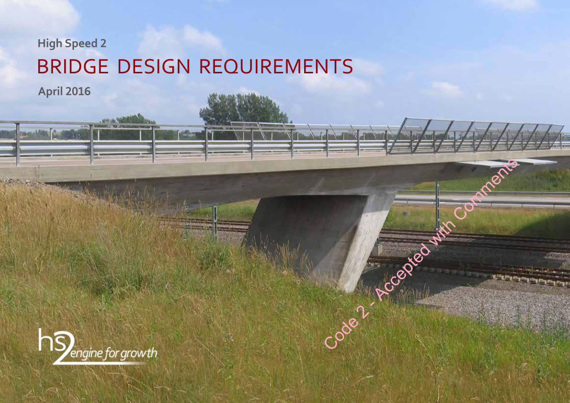
BRIDGE DESIGN REQUIREMENTSApril2016
Code 2
- Acc
epted
with
Com
ments

HS2 | Bridge Design Requirements
HS2-HS2-BR-STD-000-000004 2 Revision P05 : April 2016
Class 395 “Javelin” departing Stratford International eastbound, © mattbuck / Wikimedia Commons
Documentnumber: HS2-HS2-BR-STD-000-000004
Revision: P04
Author: C227Atkins/Grimshaw
Date: 04April2016
Revisiondetails: ForacceptanceCode 2
- Acc
epted
with
Com
ments
HS2 | Bridge Design Requirements
HS2-HS2-BR-STD-000-000004 3 Revision P04 : April 2016
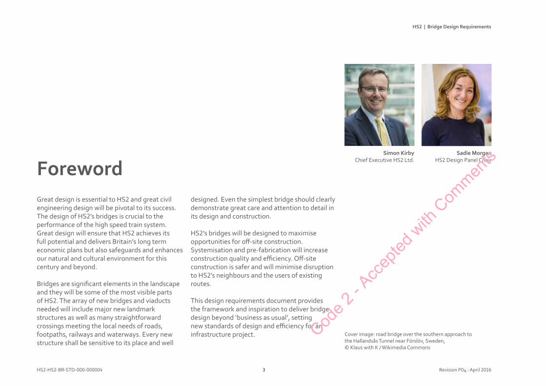
Great design is essential to HS2 and great civil engineering design will be pivotal to its success. The design of HS2’s bridges is crucial to the performance of the high speed train system. Great design will ensure that HS2 achieves its full potential and delivers Britain’s long term economic plans but also safeguards and enhances our natural and cultural environment for this century and beyond.
Bridges are significant elements in the landscape and they will be some of the most visible parts of HS2. The array of new bridges and viaducts needed will include major new landmark structures as well as many straightforward crossings meeting the local needs of roads, footpaths, railways and waterways. Every new structure shall be sensitive to its place and well
Foreworddesigned. Even the simplest bridge should clearly demonstrate great care and attention to detail in its design and construction.
HS2’s bridges will be designed to maximise opportunities for off-site construction. Systemisation and pre-fabrication will increase construction quality and efficiency. Off-site construction is safer and will minimise disruption to HS2’s neighbours and the users of existing routes.
This design requirements document provides the framework and inspiration to deliver bridge design beyond ‘business as usual’, setting new standards of design and efficiency for an infrastructure project. Cover image: road bridge over the southern approach to
the Hallandsås Tunnel near Förslöv, Sweden,© Klaus with K / Wikimedia Commons
Simon KirbyChief Executive HS2 Ltd.
SadieMorganHS2 Design Panel Chair
Code 2
- Acc
epted
with
Com
ments
HS2 | Bridge Design Requirements
HS2-HS2-BR-STD-000-000004 4 Revision P05 : April 2016
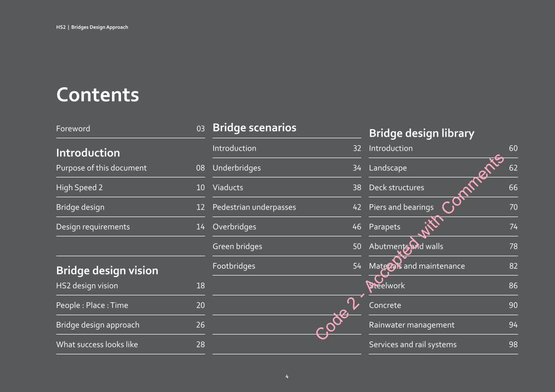
ContentsBridgescenarios
Introduction 32
Underbridges 34
Viaducts 38
Pedestrian underpasses 42
Overbridges 46
Green bridges 50
Footbridges 54
Foreword 03
Introduction Purpose of this document 08
High Speed 2 10
Bridge design 12
Design requirements 14
BridgedesignvisionHS2 design vision 18
People : Place : Time 20
Bridge design approach 26
What success looks like 28
BridgedesignlibraryIntroduction 60
Landscape 62
Deck structures 66
Piers and bearings 70
Parapets 74
Abutments and walls 78
Materials and maintenance 82
Steelwork 86
Concrete 90
Rainwater management 94
Services and rail systems 98
HS2|BridgesDesignApproach
4
Code 2
- Acc
epted
with
Com
ments
HS2 | Bridge Design Requirements
HS2-HS2-BR-STD-000-000004 5 Revision P04 : April 2016
Introduction >
Bridgedesignvision >
Bridgescenarios >
Bridgedesignlibrary >Mandatoryclauses
Unlike the convention used in HS2 technical standards this document does not differentiate mandatory clauses from main text by the use of a ‘black box’.Instead, mandatory requirements will contain the word ‘shall’ to indicate their status as a requirement.Guidance is defined by the use of the words ‘should’, ‘consider’ or ‘may’.
Code 2
- Acc
epted
with
Com
ments

IntroductionCod
e 2 - A
ccep
ted w
ith C
ommen
ts
IntroductionPurposeofthisdocument 08
HighSpeed2 10
BridgeDesign 12
DesignRequirements 14
Introduction
Code 2
- Acc
epted
with
Com
ments
HS2 | Bridge Design Requirements
HS2-HS2-BR-STD-000-000004 8 Revision P04 : April 2016
Common design
approach: Depots
Common design
approach: Open route elements
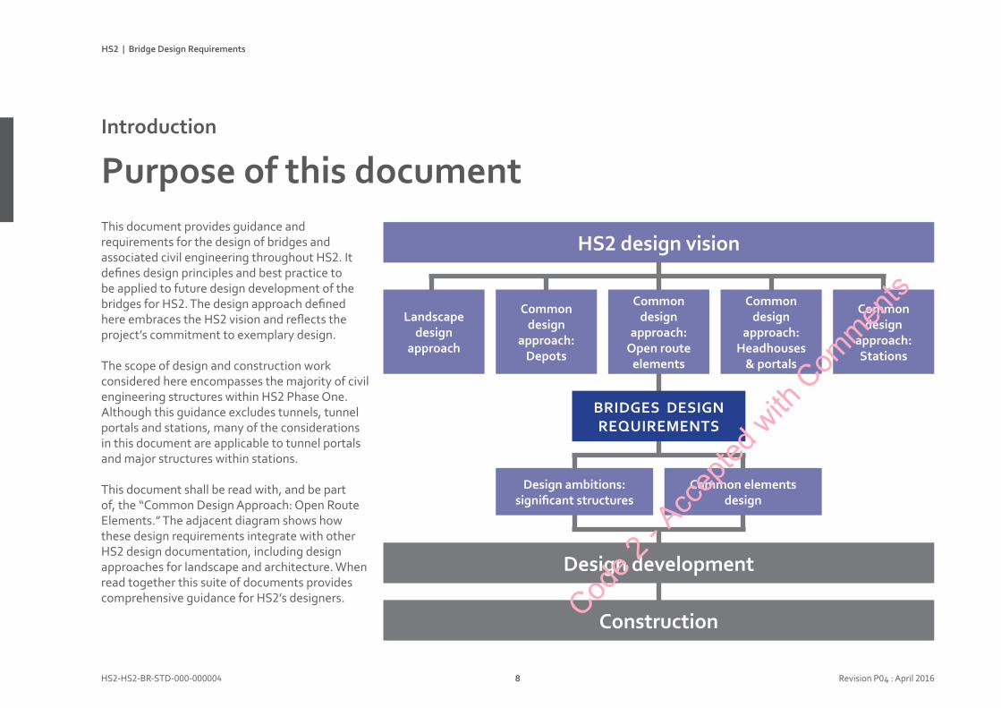
This document provides guidance and requirements for the design of bridges and associated civil engineering throughout HS2. It defines design principles and best practice to be applied to future design development of the bridges for HS2. The design approach defined here embraces the HS2 vision and reflects the project’s commitment to exemplary design.
The scope of design and construction work considered here encompasses the majority of civil engineering structures within HS2 Phase One. Although this guidance excludes tunnels, tunnel portals and stations, many of the considerations in this document are applicable to tunnel portals and major structures within stations.
This document shall be read with, and be part of, the “Common Design Approach: Open Route Elements.” The adjacent diagram shows how these design requirements integrate with other HS2 design documentation, including design approaches for landscape and architecture. When read together this suite of documents provides comprehensive guidance for HS2’s designers.
PurposeofthisdocumentIntroduction
HS2designvision
Construction
Common design
approach:Stations
Common design
approach:Headhouses &portals
Landscape design approach
BRIDGESDESIGN REQUIREMENTS
Designambitions: significantstructures
Commonelementsdesign
Designdevelopment
Code 2
- Acc
epted
with
Com
ments

HS2 | Bridge Design Requirements
HS2-HS2-BR-STD-000-000004 9 Revision P04 : April 2016
The Bridges Design Requirements are presented in three sections as follows:
Bridgedesignvision Bridgescenarios Bridgedesignlibrary
This section presents the bridge design vision for HS2 and shows how this embraces the HS2 Vision and HS2 Design Vision. The bridge design vision aims to demonstrate the highest standards of design and construction, a world class railway that creates a positive lasting legacy and provides a benchmark for the civil engineering design of major infrastructure projects.
The bridge scenarios present a range of typical HS2 bridges, illustrating the range of structures that will be required along the route. Drawing from the bridge design vision these demonstrate the design approach required for HS2. Clear design principles, with associated guidance for each type of structure, implement the bridge design vision and thus the HS2 Vision.
The bridge design library contains detailed advice for elements of design that are common across all bridge types. Some key aspects of bridge design (e.g. response to landscape) are covered in more detail in other design guides (e.g. Landscape Design Approach). This document defines how bridge design will be influenced by those key issues.
HS | Bridges Design Requirements
Design process
Appearance must be a major design imperative alongside strength, safety, construction and cost.
Aesthetics should be considered at project conception and through each stage of design. Design quality cannot be added on at the end.
Bridges should be designed by multidisciplinary teams, including engineers, landscape architects, urban designers and bridge architects, working as equals in a collaborative and integrated way.
Construction should be considered at all design stages, with early contractor involvement. Remember that contractors’ expertise and equipment varies: diff erent contractors may lead to diff erent answers.
Client, designers and contractors must all demonstrate a continuing commitment to design quality. Aesthetics must be championed and adequately weighted in selection and assessment processes. This commitment must be carried through to construction where poor workmanship and design variations place quality at risk.
Bridge design approachBridge design vision
Response to context
Each site is unique. The character of the local natural or urban landscape should be appraised to inform the bridge design. Visibility and construction access must be considered.
The visual signi cance of each bridge must be de ned: will it be a low-key structure, will it be a prominent landmark or within a sensitive setting?Make the built and natural environment as visible as possible through the bridge.
The complexity of a bridge design should be minimised in a rural setting.
Natural vegetation should be protected and augmented, with existing vegetation retained to the maximum extent practicable without impact opon operation of the railway.
Designs shall minimise the footprint of bridges (piers, abutments) so that local vegetation is maximised.
Designs shall minimise the presence and extent of hard surfaces in rural landscapes.
Bridge design
Each bridge should have a clear, understandable design concept with scale and proportions appropriate to its context.
Each structure must be elegant aesthetic composition, with a consistent design language used for all of its components. Simple repetition of standard parts or designs is not adequate, broader thinking is required.
The design of a bridge should express its fundamental structural anatomy: the structural logic and ow of forces should be apparent. The shapes of the structural members should re ect the forces acting on them.
Construction must contribute to the design concept: how a bridge is built and how it looks should work together not ght against each other.
Scale and proportion should be carefully considered, including how these are aff ected by context and daylight and shadow.
HS | Bridges Design Requirements
Green bridges will provide ecological connections across HS� for mammals, including bats, and other fauna.
HS� will have two types of green bridge:• narrow green bridges with limited planting,
typically in linear ‘troughs’• wide bridges with signifcant intensive
planting.
Intensively planted green bridges, and green tunnels, should be thoroughly integrated into their landscape surroundings, maximising connectivity of planting and animal habitats. These wide green bridges should, eff ectively, be perceived as short tunnels.
The narrower green bridges should follow the guidance established for other overbridges, including relevant footbridge design considerations. They should be clearly seen as bridges.
Green bridgesBridge design scenarios
Wide green bridge, over E�� highway, with thorougly integrated landscape design, Netherlands, ©urbanarchnow.com
HS | Bridges Design Requirements
Design Principles
Piers design must be consistent within each structure and comply with an overall HS line-wide identity
Piers and bearingsBridges design library
Special central span: piers and deck structure respond to context, spanning over river, © Heiko Dassow
Code 2
- Acc
epted
with
Com
ments

HS2 | Bridge Design Requirements
HS2-HS2-BR-STD-000-000004 10 Revision P05 : April 2016
HS2 is the largest infrastructure project ever undertaken by the UK Government, and construction is expected to commence in 2017.
Phase One of HS2 will run from London to Birmingham, a total length of 225km. Stations are proposed at Old Oak Common and Birmingham Interchange in addition to termini at London Euston and Curzon Street, Birmingham. The route will connect to the West Coast Main Line at Lichfield.
The maximum design speed for Phase One is 400kph. It will carry up to 18 trains per hour, each train being 400m long.
Phase Two of HS2 forms a ‘Y’ shape extending from the West Midlands towards Manchester and the North West, with a proposed station at Manchester Airport; and towards Leeds and the North East with proposed stations in the East Midlands and South Yorkshire.
Highspeed2Introduction
Code 2
- Acc
epted
with
Com
ments
text
HS2 | Bridge Design Requirements
HS2-HS2-BR-STD-000-000004 11 Revision P05 : April 2016
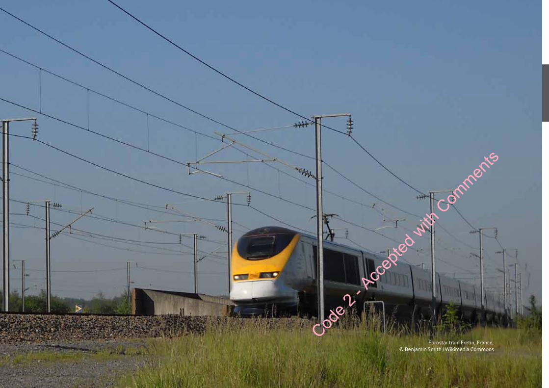
Eurostar train Fretin, France,© Benjamin Smith / Wikimedia Commons
Code 2
- Acc
epted
with
Com
ments

HS2 | Bridge Design Requirements
HS2-HS2-BR-STD-000-000004 12 Revision P05 : April 2016
Bridges will be an abundant and prominent element of High Speed 2. In place for 120 years, they should provide a legacy of excellence for future generations.
Bridge aesthetics shall be considered, from the outset, as an integral part of design and procurement processes. Bridge design will not be successful if aesthetics are considered only in an attempt to mitigate the impact of decisions that have already been made.
Bridges are engineering but also architecture. There is a need to be constantly aware of the aesthetic implications of design decisions. A talent for, and understanding of, aesthetics is essential for excellent bridge design. This places a strong emphasis on the need for integrated design within a clear overall vision.
HS2’s civil engineering designers are encouraged to include architects, ideally with experience of bridge design, within their teams: architects’ training can reinforce a focus upon integrated design.
BridgedesignIntroduction
Some bridges and viaducts, due to their scale or location, will be symbolic landmark structures, naturally attracting special attention. The aesthetic principles defined in this document shall be applicable to all of HS2’s bridges, the minor structures as well as the special one-offs. Even the humblest of HS2’s bridges should have good manners and a degree of finesse.
This document does not provide a formula for good bridge design and there are always exceptions to design ‘rules.’ Unlike technical standards, hard and fast rules for appearance are not easily defined, but there is substantial and useful guidance that should be followed. The intent is to define principles and considerations that will eliminate the worst aspects of bridge design and encourage the best.
Code 2
- Acc
epted
with
Com
ments
HS2 | Bridge Design Requirements
HS2-HS2-BR-STD-000-000004 13 Revision P05 : April 2016
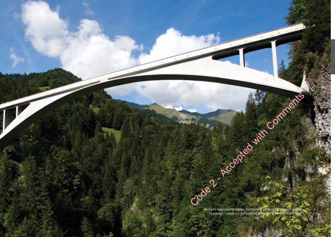
Maillart’s Salginatobel bridge, Switzerland produced the lowest tender in a design / construct competition © Rama / Wikimedia Commons
Code 2
- Acc
epted
with
Com
ments
HS2 | Bridge Design Requirements
HS2-HS2-BR-STD-000-000004 14 Revision P04 : April 2016
Highspeedrailways
High speed rail is a relatively new type of infrastructure in the UK, with only one line currently in operation. Experience from this line, HS1, has been a key source in consideration of standards for HS2. In addition, there are established International, European and British Standards that the works shall comply with.
Whilst many of these standards deal with ‘technical’ matters, some will have a significant impact upon appearance and user experience. For example, requirements for the height and construction of highway and footbridge parapets.
DesignrequirementsIntroduction
Civilengineeringdesign
Compliance with the UK Highways Agency’s Design Manual for Roads and Bridges (DMRB) shall be used as the core bridge design standard for HS2. As design progresses there may be scope to either reduce or increase the requirements where this can be demonstrated to be appropriate and justifiable.
Guidance in the following core reference documents shall be applied to all HS2 bridge design:
• DMRB Volume 1, Section 3, Part 11: The Design and Appearance of Bridges (BA 41/98, 1998)
• The Appearance of Bridges and Other Highway Structures (Highways Agency, 1996).
HS2alignment
HS2’s horizontal (plan) and vertical (level) alignment is now substantially fixed, along with existing highway and footway levels. Alignment is largely defined by design for the Hybrid Bill, including a series of amendments.
Limits of deviation will leave some scope for very minor changes to alignment. Therefore, bridge structures which could significantly affect the alignment can no longer be considered.
Code 2
- Acc
epted
with
Com
ments

HS2 | Bridge Design Requirements
HS2-HS2-BR-STD-000-000004 15 Revision P04 : April 2016
HS2requirements
The HS2 spatial requirements are defined within HS2-HS2-CV-STD-000-000001 ‘Technical Standard, Spatial Arrangements’. It sets out the required dimensions for generic cross sections along the full route, including bridges and viaducts. In addition, there are various span and headroom clearance requirements for overbridges. These are detailed in Sections 5 and 6 of the Requirements for Spatial Arrangements document.
The design of structures shall comply with the technical specification for interoperability (TSI) for dynamic performance
All structures shall have a design life of 120 years.
HS2’s preference is to minimise future maintenance requirements. Accessibility for maintenance is a critically important consideration and needs to be considered throughout. This needs to include consideration of whether it is practicable to eliminate maintenance altogether in critical locations, i.e. those that would require track possessions.
Buildoff-site
HS2’s Efficiency Challenge Programme has led to a strategy to maximise off-site construction. On site construction should only be adopted as the exception or to support an off-site solution.
To pursue this agenda, HS2 has identified two distinctive routes to maximise off-site construction:
• Systematised: asset types that include repetition but need a degree of tailoring for their context.
• Standardised: specific proprietary products and standard product designs
Bridges, viaducts, wing walls and retaining walls have all been identified as asset families appropriate for having systemised designs and design rules. The objective is to avoid repeated design activities and provide supply chains with the greatest scope for improving productivity. HS2’s current view is that there will be a need for limited customisation of some of these to accommodate alternative planning contexts.
It is important to recognize the significance of some asset types being very directly linked to the performance of the high speed train system itself. Within HS2, there is a strong presumption in favour of systemisation for viaducts and underbridges because the performance of the high speed train system needs to be thoroughly validated, including these elements. Verification can be complex and there is a clear case for only doing this once and having a standard design concept for each asset that forms part of the system. Once the designs and design rules have been established they will need to be applied rigorously.
Standard designs may be developed for components that repeat throughout the HS2 system. Any standard designs may need multiple suppliers for commercial or capacity reasons, whilst minimising the need to retest or certify multiple designs. Elements of the bridges works could become standard designs, for example, a family of precast concrete parapet panels or precast concrete beams.Cod
e 2 - A
ccep
ted w
ith C
ommen
ts

Bridgedesignvision
Code 2
- Acc
epted
with
Com
ments
BridgedesignvisionHS2designvision 18
People:Place:Time 20
Bridgedesignapproach 26
Whatsuccesslookslike 28
Bridgedesignvision
Code 2
- Acc
epted
with
Com
ments

HS2 | Bridge Design Requirements
HS2-HS2-BR-STD-000-000004 18 Revision P04 : April 2016
The HS2 Design Vision sets out the role that design can play in making High Speed Two a catalyst for growth across Britain. It sets out our aspiration for designing the UK’s new national high-speed rail network. It focuses on those things that will lift us beyond the ordinary and provides us with the means to constantly critique and check that we are on course.
HS2 is a project that will set designers, from the widest range of disciplines, the challenge of reaching new heights of creativity and innovation in everything they design.
Given the scale and importance of HS2 to the nation, every design task is critical. The system will be delivered through all the designed elements coming together. All the fundamental principles of good design shall apply. It all has to look good and work well and that means meeting rigorous requirements. But we are looking to achieve even more – something transformational – and this will call for great ingenuity.
HS2DesignVisionBridgedesignvision
“ We aim to enhance the lives of future generations of people in Britain by designing a transformational rail system that is admired around the world.”
HS2 Design Vision, 2015Cod
e 2 - A
ccep
ted w
ith C
ommen
ts
HS2 | Bridge Design Requirements
HS2-HS2-BR-STD-000-000004 19 Revision P04 : April 2016
HS2 | Landscape Design Approach
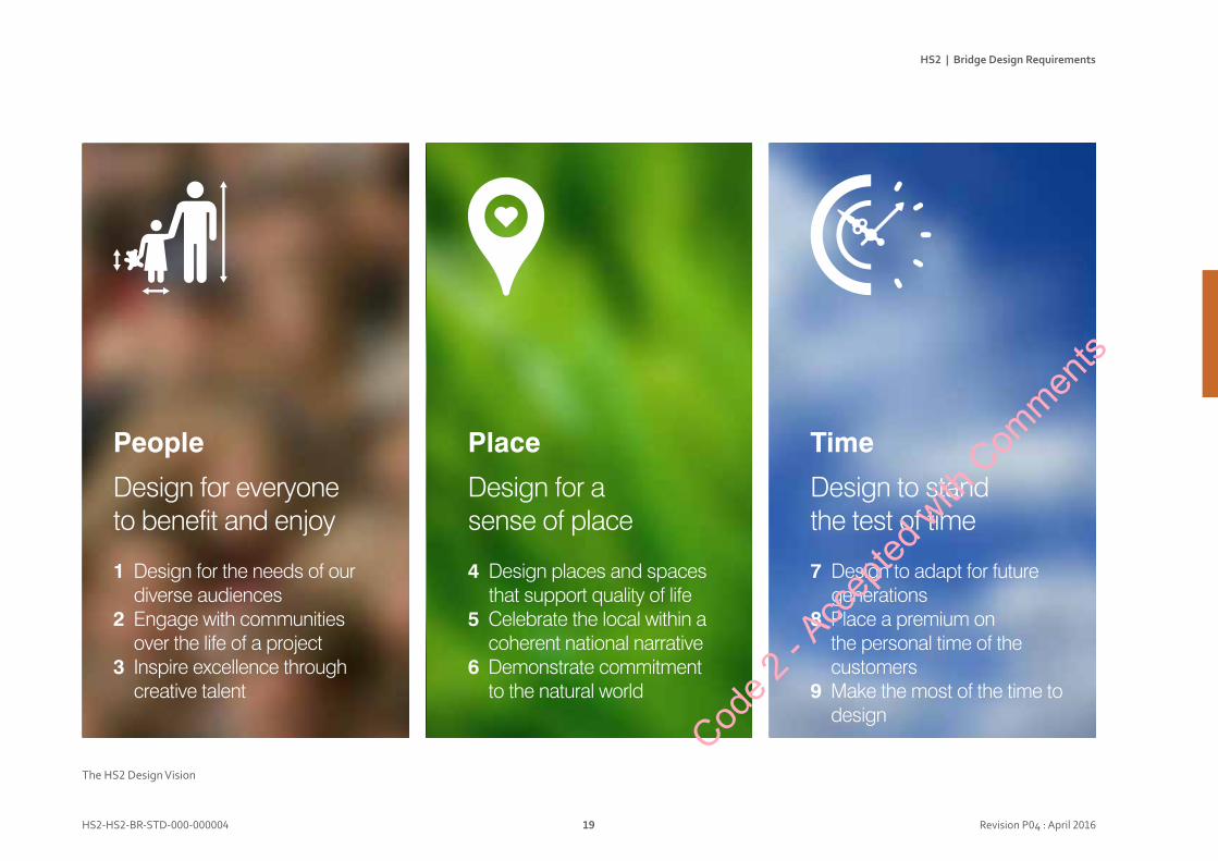
Design for everyone to benefit and enjoy
1 Design for the needs of our diverse audiences
2 Engage with communities over the life of a project
3 Inspire excellence through creative talent
Design for a sense of place
4 Design places and spaces that support quality of life
5 Celebrate the local within a coherent national narrative
6 Demonstrate commitment to the natural world
Design to stand the test of time
7 Design to adapt for future generations
8 Place a premium on the personal time of the customers
9 Make the most of the time to design
People Place Time
The HS2 Design Vision
19
The HS2 Design Vision
HS2 | Landscape Design Approach
Design for everyone to benefit and enjoy
1 Design for the needs of our diverse audiences
2 Engage with communities over the life of a project
3 Inspire excellence through creative talent
Design for a sense of place
4 Design places and spaces that support quality of life
5 Celebrate the local within a coherent national narrative
6 Demonstrate commitment to the natural world
Design to stand the test of time
7 Design to adapt for future generations
8 Place a premium on the personal time of the customers
9 Make the most of the time to design
People Place Time
The HS2 Design Vision
19
Code 2
- Acc
epted
with
Com
ments
HS2 | Bridge Design Requirements
HS2-HS2-BR-STD-000-000004 20 Revision P04 : April 2016
Userexperience
Whilst passengers are the obvious “users” of HS2, many other people will be affected by the design of HS2’s bridges. The needs of all of them shall be considered, especially key impacts upon:• neighbours• views and the visibility of structures• those travelling on routes crossing HS2• maintenance and construction staff
The project’s neighbouring communities will, initially, be affected by construction and then by impact upon views and/or noise once the line is operational.
PeopleBridgedesignvision
Many people will be affected by the way roads, footpaths, railways and waterways cross the HS2 route. The bridges that provide these crossings will have a significant influence.
Those working to build and maintain HS2 shall be considered. Bridges and viaducts shall be safe to build, maximising off-site construction and pre-fabrication. Structures shall be simple to maintain with convenient secure access and space to work safely.
Stakeholders
Multiple stakeholders will be affected by the design and construction of HS2’s bridges and viaducts. The HS2 Design Vision strongly advocates stakeholder consultation informing design development.
Discussions with stakeholders may also reveal areas where HS2 designs could be modified to the benefit of both parties. Stakeholders should be encouraged to describe and define their key concerns for people and their environment, including any special characteristics of their locations.
Code 2
- Acc
epted
with
Com
ments
HS2 | Bridge Design Requirements
HS2-HS2-BR-STD-000-000004 21 Revision P04 : April 2016
23
1 DRAFT
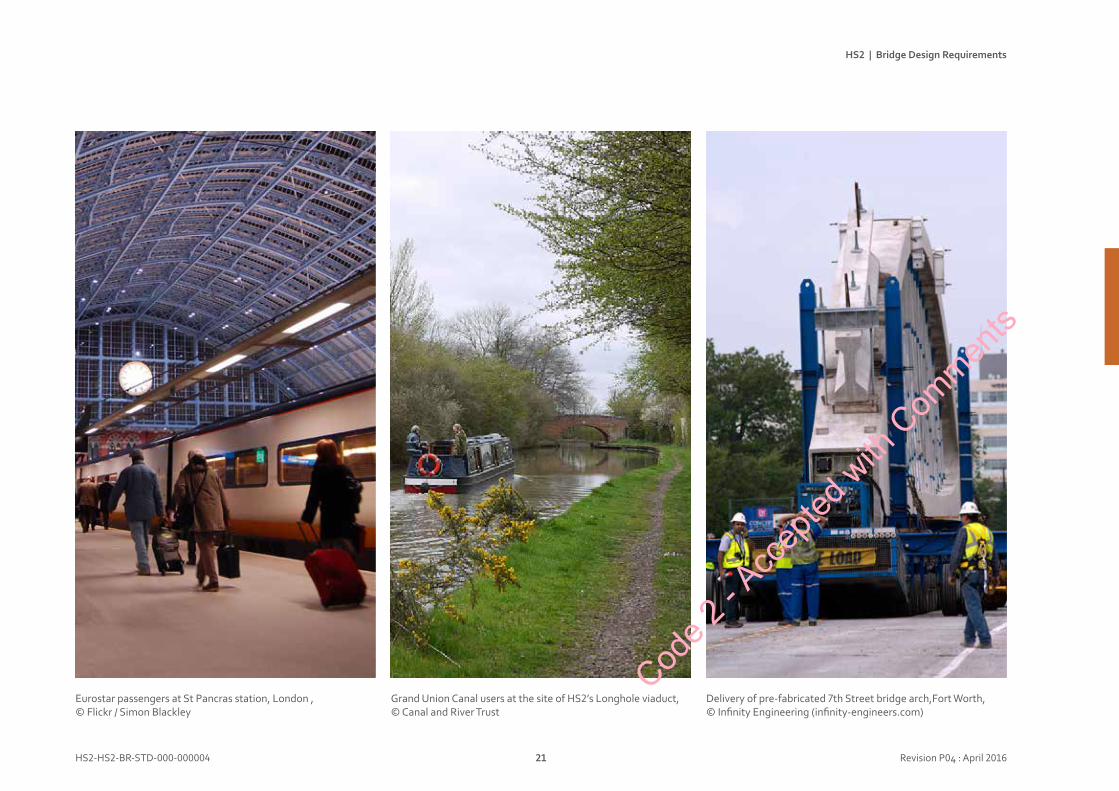
Grand Union Canal users at the site of HS2’s Longhole viaduct,© Canal and River Trust
Eurostar passengers at St Pancras station, London ,© Flickr / Simon Blackley
Delivery of pre-fabricated 7th Street bridge arch,Fort Worth, © Infinity Engineering (infinity-engineers.com)
Code 2
- Acc
epted
with
Com
ments

HS2 | Bridge Design Requirements
HS2-HS2-BR-STD-000-000004 22 Revision P04 : April 2016
Context
HS2 passes through a broad variety of locations, from dense urban sites in London and Birmingham to valued open countryside. A number of locations are considered to be especially environmentally or visually sensitive.
The context for each bridge shall be thoroughly analysed through a landscape assessment, including urban design in built-up areas. Bridge design shall be informed by place, with a sensitive response to local character, history and future needs and plans. The scale of the structure and its visibility shall be considered. Bridges shall be integrated with the surrounding landscape and shall not be examples of engineering design in isolation.
PlaceBridgedesignvision
In designing and constructing HS2’s bridges and viaducts, particularly special care shall be taken where:• users are passing by slowly• it is possible to get close to the structures• many people can see the structures• they are in a landscape acknowledged to be of
visual importance
All of these places require special attention to design because of the higher levels of scrutiny that their structures will be subject to.
Uniformityorvariety
There is potential tension between HS2’s aim for standardisation and systemisation for off-site construction and the HS2 Design Vision which seeks “design for a sense of place.”
In creating identity, HS2’s Design Vision aims to “celebrate the local within a coherent national narrative” where “local projects reflect their context but contribute to HS2’s overall identity.” It is clear that local variation will be necessary and appropriate but a consistent linewide approach will also have value.
Careful design exploration is now needed to define the appropriate balance between overall systematic linewide repetition and local variation. This shall be defined for each individual structure or location based upon clear analysis of place.
Code 2
- Acc
epted
with
Com
ments
HS2 | Bridge Design Requirements
HS2-HS2-BR-STD-000-000004 23 Revision P04 : April 2016
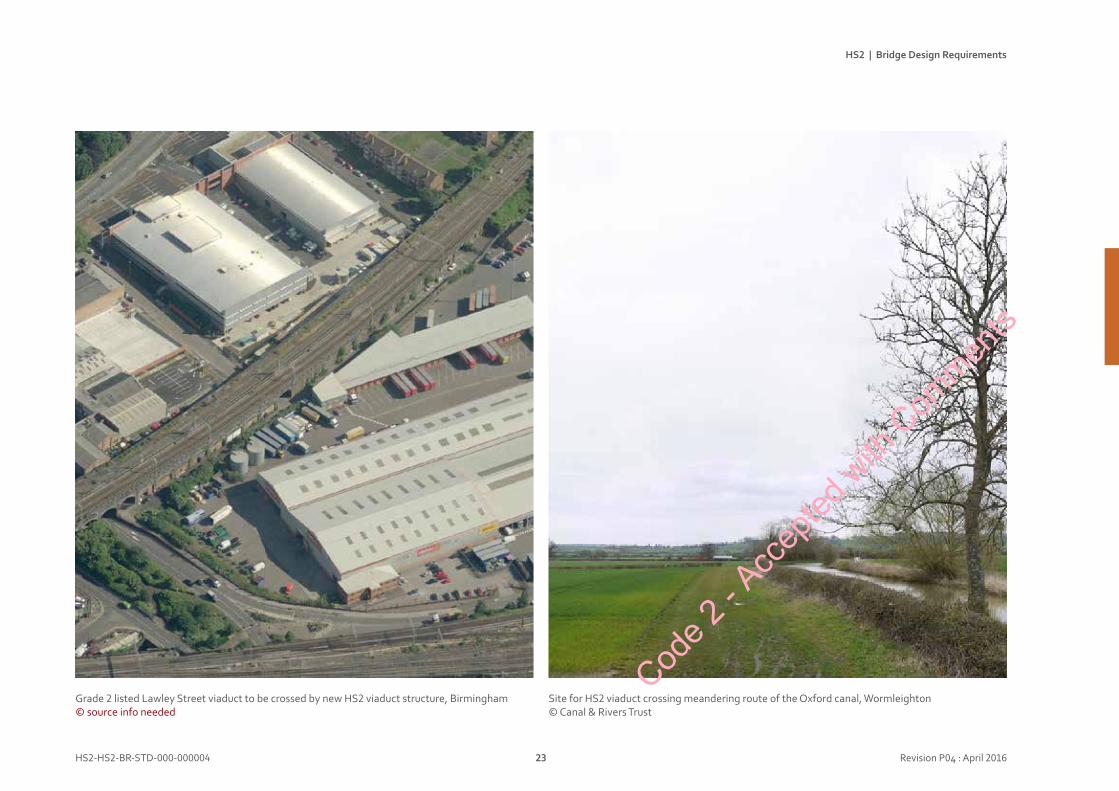
Site for HS2 viaduct crossing meandering route of the Oxford canal, Wormleighton© Canal & Rivers Trust
15
1 DRAFT
Grade 2 listed Lawley Street viaduct to be crossed by new HS2 viaduct structure, Birmingham © source info needed
Code 2
- Acc
epted
with
Com
ments
HS2 | Bridge Design Requirements
HS2-HS2-BR-STD-000-000004 24 Revision P04 : April 2016
Designlife
High Speed 2 has a design life of 120 years. Within this overall lifespan, trains and railway equipment will be renewed at regular intervals. Experience strongly suggests that the stations will also be subject to significant change over their lives.
In this context the landscape and civil engineering structures that define and support the HS2 alignment will be the longest lasting parts of the project. Bridges and viaducts will be the most visible of these structures throughout HS2. The significance of this legacy for future generations demands great care and attention to the quality of design, construction and maintenance for HS2’s bridges. They shall be of exemplary quality: a model of the very best practice.
TimeBridgedesignvision
Constructiontime
HS2 is the UK’s biggest infrastructure project. Its construction will take significant time, inevitably affecting the line’s neighbours and users of existing infrastructure crossing the route. Off-site manufacturing, maximising the use of pre-fabrication, has significant potential to reduce the amount of time spent on site with benefits for the construction workforce, neighbours and local stakeholders. HS2’s bridge designs shall consider modern methods of construction and design for manufacture and assembly to reduce the disruption that construction may cause to communities along the line.
Durability
HS2’s design life is an onerous requirement for bridge structures and materials. Long term durability is a fundamental design requirement. In addition to structural performance, and the impacts of corrosion and deterioration, long term visual ‘performance’ shall be considered. Structural forms, details and materials shall be designed to weather well over time.
Maintenance and inspection regimes have the potential to disrupt regular operation of the railway, affecting the reliability of train timetables and operations. This impact upon the valuable time of HS2’s passengers shall be controlled and minimised.
Bridge structures shall be designed to reduce the need for inspection and maintenance to minimum levels without affecting durability or safety. This requires maintenance to be considered from the very earliest design stages. Where elements that require inspection or maintenance cannot be eliminated, they should be located so that access does not require track possessions.Cod
e 2 - A
ccep
ted w
ith C
ommen
ts
HS2 | Bridge Design Requirements
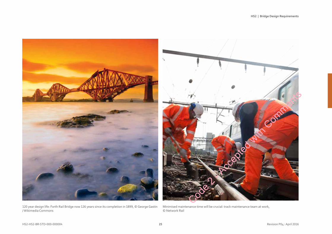
HS2-HS2-BR-STD-000-000004 25 Revision P04 : April 2016
120 year design life: Forth Rail Bridge now 126 years since its completion in 1899, © George Gastin / Wikimedia Commons
Minimised maintenance time will be crucial: track maintenance team at work, © Network Rail
Code 2
- Acc
epted
with
Com
ments

HS2 | Bridge Design Requirements
HS2-HS2-BR-STD-000-000004 26 Revision P04 : April 2016
Designprocess
Appearance shall be a major design imperative alongside strength, safety, construction and cost.
Aesthetics shall be considered at project conception and through each stage of design. Design quality cannot be added on at the end.
Bridges shall be designed by multidisciplinary teams, including engineers, landscape architects, urban designers and bridge architects, working as equals in a collaborative and integrated way.
Construction shall be considered at all design stages, with early contractor involvement. Remember that contractors’ expertise and equipment varies: different contractors may lead to different answers.
Client, designers and contractors shall all demonstrate a continuing commitment to design quality. Aesthetics shall be championed and adequately weighted in selection and assessment processes. This commitment shall be carried through to construction where poor workmanship and design variations place quality at risk.
BridgedesignapproachBridgedesignvision
Responsetocontext
Each site is unique. The character of the local natural or urban landscape shall be appraised to inform the bridge design. Visibility and construction access shall be considered.
The visual significance of each bridge shall be defined: will it be a low-key structure, will it be a prominent landmark or within a sensitive setting?The built and natural environment shall be as visible as possible through the bridge.
The complexity of a bridge design should be minimised in a rural setting.
Natural vegetation should be protected and augmented, with existing vegetation retained to the maximum extent practicable without impact upon operation of the railway.
Designs shall minimise the footprint of bridges (piers, abutments) so that local vegetation is maximised.
Designs shall minimise the presence and extent of hard surfaces in rural landscapes.
Bridgedesign
Each bridge shall have a clear, understandable design concept with scale and proportions appropriate to its context.
Each structure shall be elegant aesthetic composition, with a consistent design language used for all of its components. Simple repetition of standard parts or designs is not adequate, broader thinking is required.
The design of a bridge should express its fundamental structural anatomy: the structural logic and flow of forces should be apparent. The shapes of the structural members should reflect the forces acting on them.
Construction shall contribute to the design concept: how a bridge is built and how it looks should work together not fight against each other.
Scale and proportion shall be carefully considered, including how these are affected by context and daylight and shadow.Cod
e 2 - A
ccep
ted w
ith C
ommen
ts
HS2 | Bridge Design Requirements
HS2-HS2-BR-STD-000-000004 27 Revision P04 : April 2016
Where an essentially symmetrical concept is proposed, the built result should be symmetrical in its setting out and in its detail. Where asymmetric designs are proposed they should be clearly and boldly asymmetric.
Simplicity is encouraged, but not crudity. Simplicity is seen as refinement, taking time and effort, it is not a lack of detail or articulation.
Bridges’ form and detail should reflect the flow of forces, honestly showing structure and materials.
Articulation, the quality and quantity of expressed detail, is critical to the character of a bridge. Articulation of detail shall be consciously manipulated and edited, choosing which elements or junctions to emphasise and which to hide or subdue.
The character of components and details shall be consistent and compatible with the overall design concept. This could include elements of contrast.
Where components repeat, order and rhythm shall be carefully considered. Modules and grids should be used to ensure that the relationships (sizes, locations and alignment) between all elements are coordinated.
Bridge design should not rely on colour, but may be enhanced by it. Self-finished materials are strongly preferred. There may be cases where pigmented concrete or painted steel could be considered.
Functional lighting shall be considered at the outset and discreetly coordinated with the structure. A few structures may justify feature lighting but the benefits, impact and maintenance costs shall be carefully considered.
Facilities for maintenance shall be discreetly integrated, not afterthoughts. The design, location and coordination of doorways, hatches, walkways and gantries shall be neat and unobtrusive.
Line-wideidentity
HS2 bridges shall follow an identifiable pattern along the route. There should also be locations with special distinctive designs. This approach aligns with precedents from other major engineering projects, for example the M1.
Families of bridge types, and their requirements, shall be defined. Each family should have model designs with considerable flexibility for variation (span, width, height, etc.). This will enable family resemblance and systemised production of standard pieces. The model designs will provide clear design intent for contracting teams
Designs for component families shall also be developed to provide a systemised kit of parts.
It is appropriate to have carefully located specials and one-off structures. Whilst having distinctive designs, they should adopt key components or characteristic from the families to provide a link to the broader line identity.
The HS2 bridges shall have family resemblance, with variety: family members not identical clones!
Code 2
- Acc
epted
with
Com
ments
HS2 | Bridge Design Requirements
HS2-HS2-BR-STD-000-000004 28 Revision P05 : April 2016
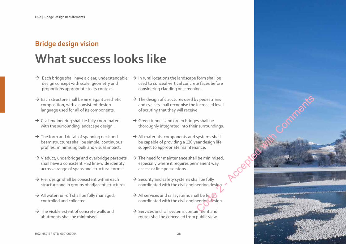
àEach bridge shall have a clear, understandable design concept with scale, geometry and proportions appropriate to its context.
àEach structure shall be an elegant aesthetic composition, with a consistent design language used for all of its components.
àCivil engineering shall be fully coordinated with the surrounding landscape design .
àThe form and detail of spanning deck and beam structures shall be simple, continuous profiles, minimising bulk and visual impact.
àViaduct, underbridge and overbridge parapets shall have a consistent HS2 line-wide identity across a range of spans and structural forms.
àPier design shall be consistent within each structure and in groups of adjacent structures.
àAll water run-off shall be fully managed, controlled and collected.
àThe visible extent of concrete walls and abutments shall be minimised.
WhatsuccesslookslikeBridgedesignvision
àIn rural locations the landscape form shall be used to conceal vertical concrete faces before considering cladding or screening.
àThe design of structures used by pedestrians and cyclists shall recognise the increased level of scrutiny that they will receive.
àGreen tunnels and green bridges shall be thoroughly integrated into their surroundings.
àAll materials, components and systems shall be capable of providing a 120 year design life, subject to appropriate maintenance.
àThe need for maintenance shall be minimised, especially where it requires permanent way access or line possessions.
àSecurity and safety systems shall be fully coordinated with the civil engineering design.
àAll services and rail systems shall be fully coordinated with the civil engineering design.
àServices and rail systems containment and routes shall be concealed from public view.
Code 2
- Acc
epted
with
Com
ments
HS2 | Bridge Design Requirements
HS2-HS2-BR-STD-000-000004 29 Revision P05 : April 2016
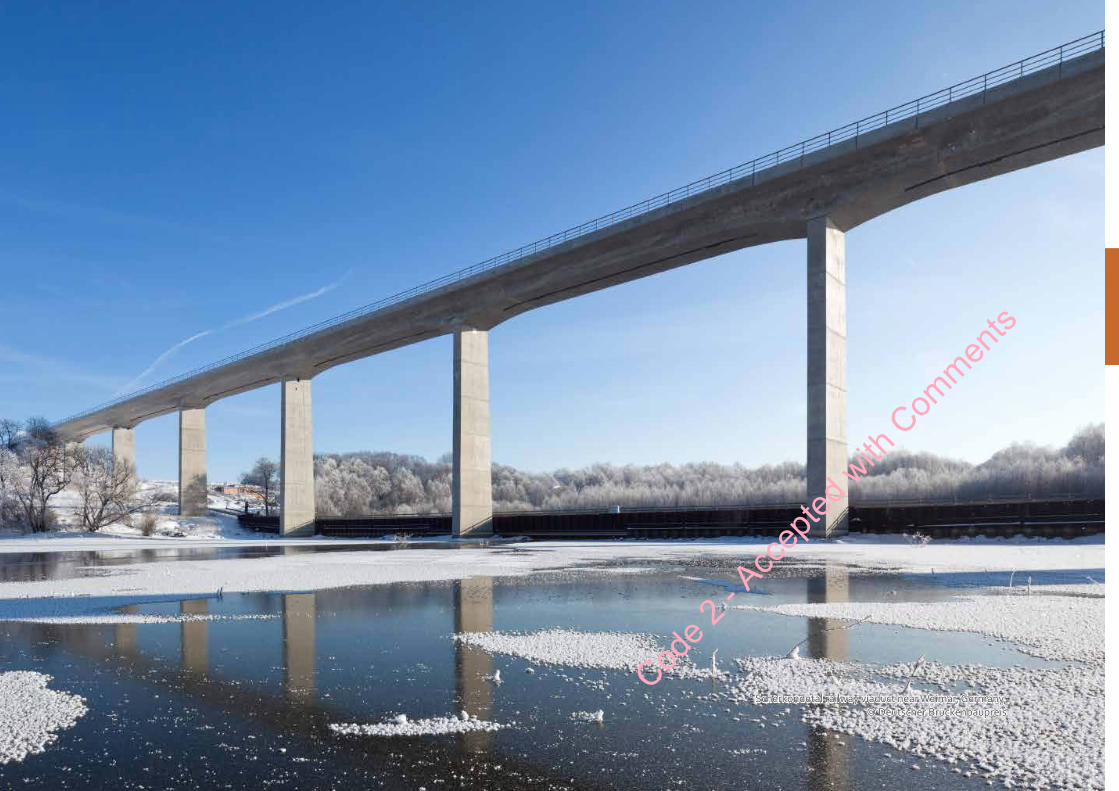
Scherkondetal railway viaduct near Weimar, Germany,© Deutscher Brückenbaupreis
Code 2
- Acc
epted
with
Com
ments

Bridgesecenarios
Code 2
- Acc
epted
with
Com
ments
Bridgesecenarios
Bridgescenarios
Introduction 32
Underbridges 34
Viaducts 38
Pedestrianunderpasses 42
Overbridges 46
Greenbridges 50
Footbridges 54Code 2
- Acc
epted
with
Com
ments
HS2 | Bridge Design Requirements
HS2-HS2-BR-STD-000-000004 32 Revision P05 : April 2016
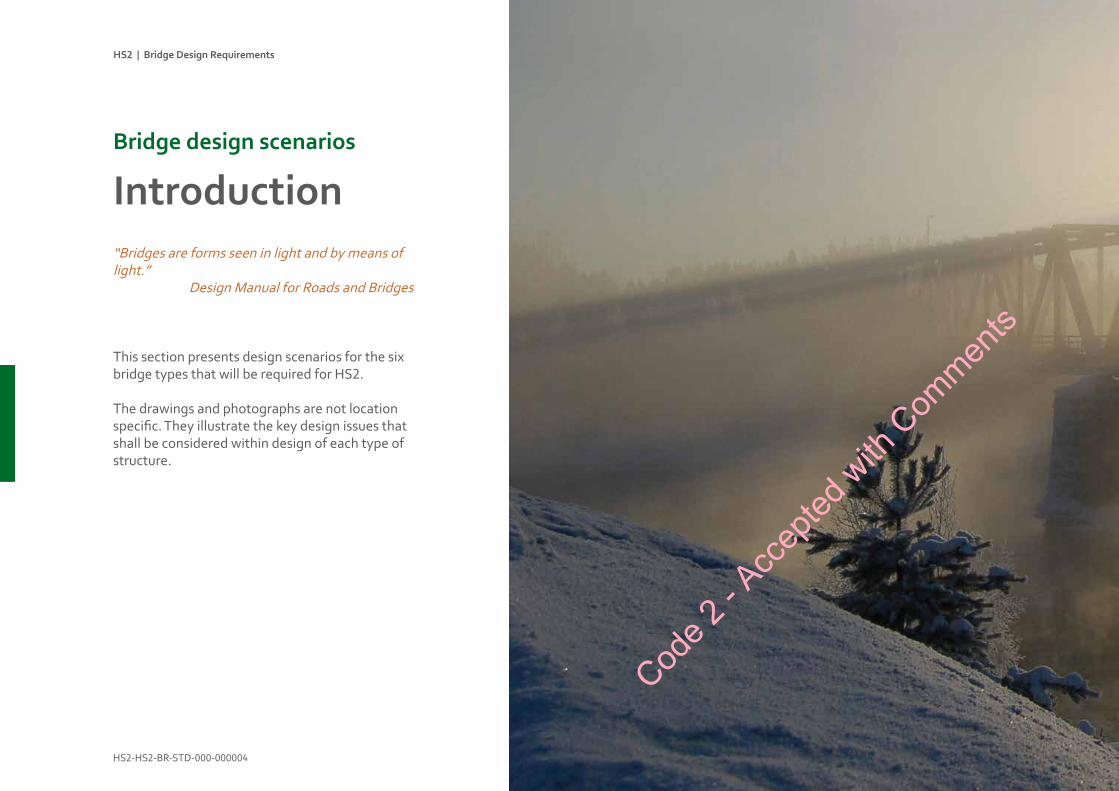
“Bridges are forms seen in light and by means of light.”
Design Manual for Roads and Bridges
This section presents design scenarios for the six bridge types that will be required for HS2.
The drawings and photographs are not location specific. They illustrate the key design issues that shall be considered within design of each type of structure.
IntroductionBridgedesignscenarios
Code 2
- Acc
epted
with
Com
ments
HS2 | Bridge Design Requirements
HS2-HS2-BR-STD-000-000004 33 Revision P05 : April 2016
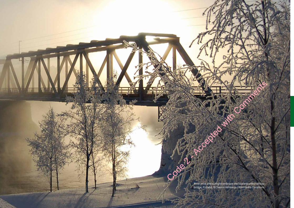
River mist and sunlight embrace the Vaalankurkku railway bridge, Finland, © Teemu Vehkaoja / Wikimedia Commons
Code 2
- Acc
epted
with
Com
ments
HS2 | Bridge Design Requirements
HS2-HS2-BR-STD-000-000004 34 Revision P04 : April 2016
UnderbridgesBridgedesignscenarios
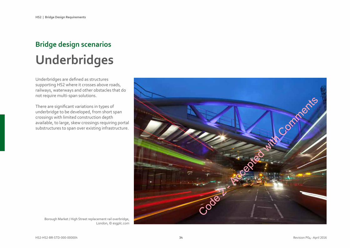
Underbridges are defined as structures supporting HS2 where it crosses above roads, railways, waterways and other obstacles that do not require multi-span solutions.
There are significant variations in types of underbridge to be developed, from short span crossings with limited construction depth available, to large, skew crossings requiring portal substructures to span over existing infrastructure.
Borough Market / High Street replacement rail overbridge, London, © esgplc.com
Code 2
- Acc
epted
with
Com
ments
HS2 | Bridge Design Requirements
HS2-HS2-BR-STD-000-000004 35 Revision P04 : April 2016
Designconsiderations
• Assess what the appropriate minimum clearance should be below low underbridge decks. The landscape design or extents of embankments shall be adjusted to achieve a good result.
• Steel half-through decks will be used for some replacement under-bridges. Their design shall be sympathetic to their locations and any existing piers.
• The visual impact of junctions with, and adaptations to, existing structures shall be thoroughly considered. The resulting assemblies shall be well composed and visually coherent. Purely pragmatic adaptations are not acceptable.
• Where existing masonry abutments are used or extended, new works shall match and be sympathetic to design of existing.
• Where existing structures are to be adapted, design features of existing works should be respected if retained. The geometry of new works shall sit happily with the old and be adjusted to suit.
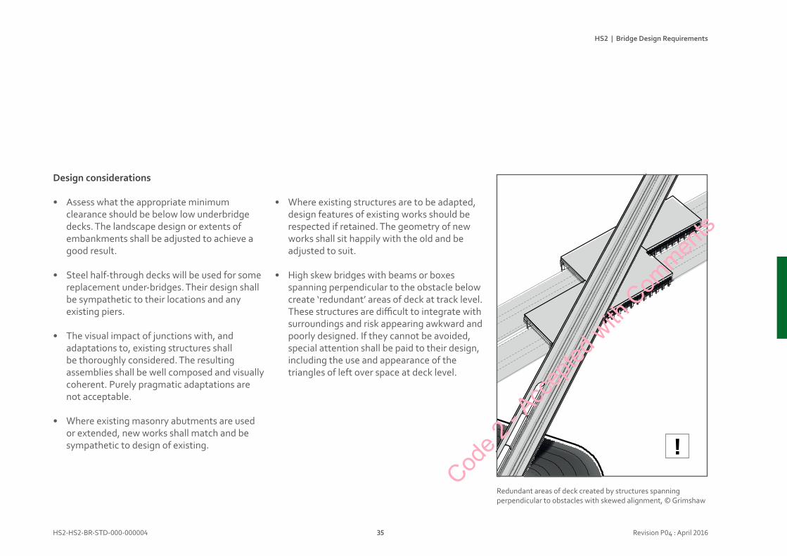
• High skew bridges with beams or boxes spanning perpendicular to the obstacle below create ‘redundant’ areas of deck at track level. These structures are difficult to integrate with surroundings and risk appearing awkward and poorly designed. If they cannot be avoided, special attention shall be paid to their design, including the use and appearance of the triangles of left over space at deck level.
Redundant areas of deck created by structures spanning perpendicular to obstacles with skewed alignment, © Grimshaw
!Cod
e 2 - A
ccep
ted w
ith C
ommen
ts
HS2 | Bridge Design Requirements
HS2-HS2-BR-STD-000-000004 36 Revision P04 : April 2016
UnderbridgesBridgedesignscenarios
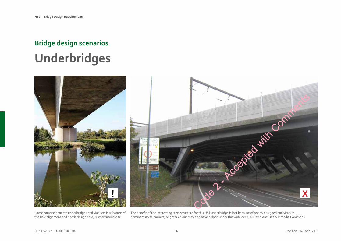
The benefit of the interesting steel structure for this HS1 underbridge is lost because of poorly designed and visually dominant noise barriers, brighter colour may also have helped under this wide deck, © David Anstiss / Wikimedia Commons
Low clearance beneath underbridges and viaducts is a feature of the HS2 alignment and needs design care, © charentelibre.fr
! X
Code 2
- Acc
epted
with
Com
ments
HS2 | Bridge Design Requirements
HS2-HS2-BR-STD-000-000004 37 Revision P04 : April 2016
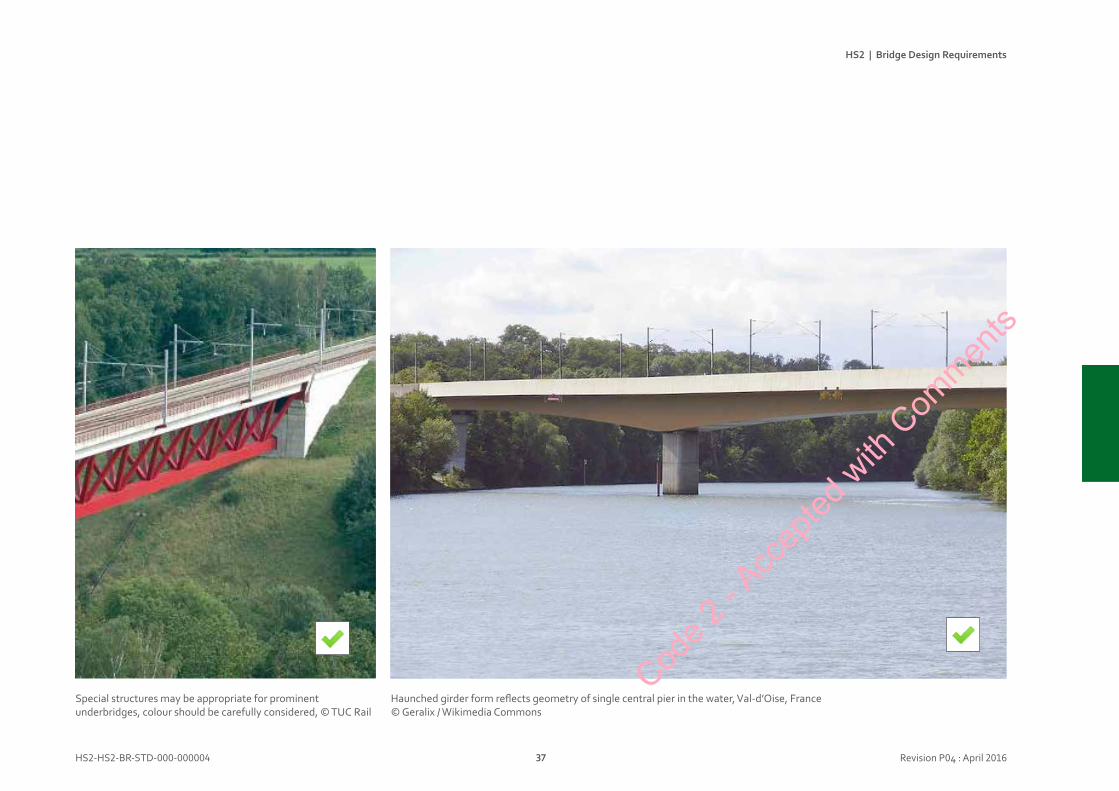
Haunched girder form reflects geometry of single central pier in the water, Val-d’Oise, France © Geralix / Wikimedia Commons
Special structures may be appropriate for prominent underbridges, colour should be carefully considered, © TUC Rail
Code 2
- Acc
epted
with
Com
ments

HS2 | Bridge Design Requirements
HS2-HS2-BR-STD-000-000004 38 Revision P04 : April 2016
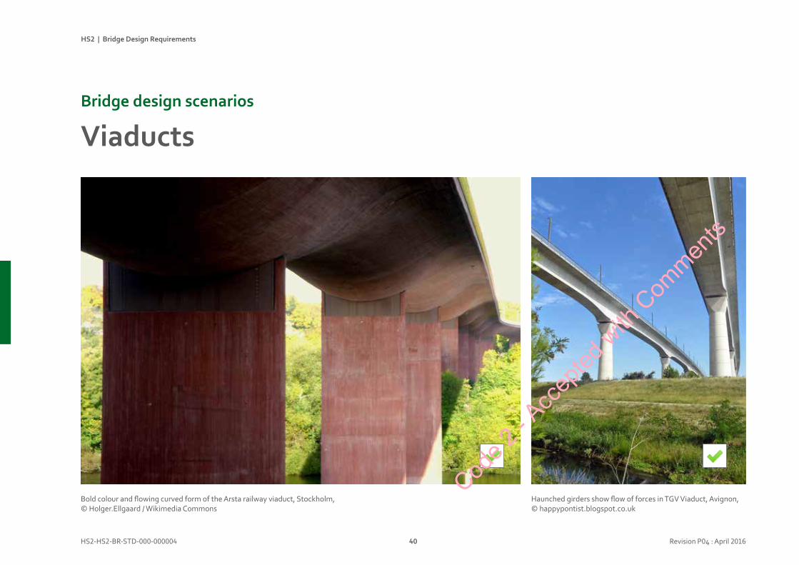
ViaductsBridgedesignscenarios
Viaducts are defined as structures with two or more spans carrying HS2 track alignment over flood plains or other obstacles, including other HS2 tracks in some cases, at bifurcations, junctions and spurs. They are essentially a specific type of underbridge, with more than a single span.
The majority of the viaducts will be in rural / open landscapes. Although typically arranged as twin parallel tracks, in some cases they are single track, paired parallel tracks (4 track) or specials with 5 or 3 tracks plus merging / splitting lines.
The appearance of viaducts is particularly important: they will be major features in the landscape, potentially dominating the nature of the existing environment.
HS2 will have a large number of ‘low-level’ viaducts, with limited clearance over the ground below. For aesthetic reasons, the height of the viaduct soffit above ground level will be crucial in determining appropriate spans.
Concrete motorway viaduct reinforced with steel for larger span, Meaux viaduct, France, © MOSSOT / Wikimedia Commons
Code 2
- Acc
epted
with
Com
ments
HS2 | Bridge Design Requirements
HS2-HS2-BR-STD-000-000004 39 Revision P04 : April 2016
Designconsiderations
• The spans within each viaduct should be rationalised and made equal. Shorter spans are permitted at abutments.
• Special long spans should only occur over significant special features, e.g. waterways, major roads.
• Assess what the appropriate minimum clearance should be below low viaduct decks. The landscape design or extent of embankments shall be adjusted to achieve a good result.
• Design proposals shall minimise the deck depth for low-level viaducts to maximise the views and clearance beneath them.
• The soffit of many viaducts, particularly those passing over canals, pathways and urban areas, will be easily visible to passengers or passers-by so it is a crucial design feature.
• Where viaducts are visible to the public at close range, care shall be taken to achieve neat joints between pre-cast segments.
• The ability to skew piers or use offset pairs of piers is crucial: to reduce long spans and to improve the relationship with routes, spaces and views below the deck. Where these issues are important, deck structures that allow skewed or offset piers shall be chosen.
• Special conditions may dictate the design for viaduct structures. For example, where two track viaducts divide into two single track structures twin box structures shall be used.
• Special junctions and components shall be handled neatly, junctions between forms shall be visually clean and well resolved.
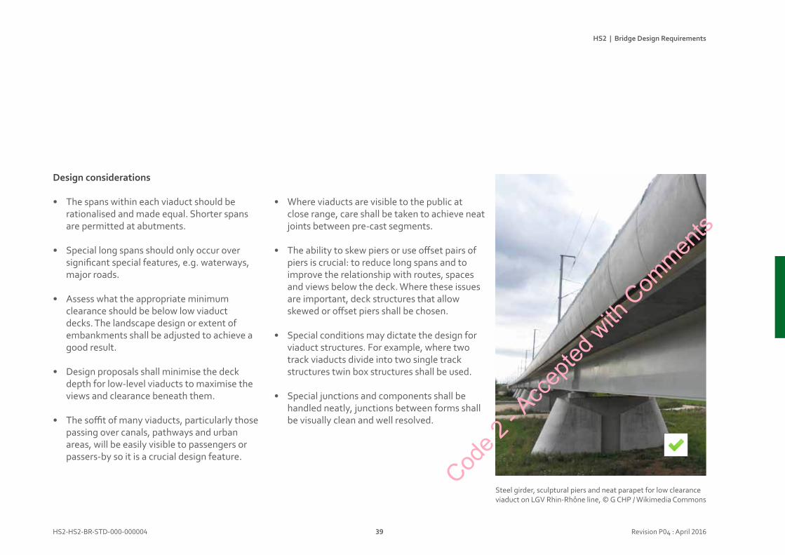
Steel girder, sculptural piers and neat parapet for low clearance viaduct on LGV Rhin-Rhône line, © G CHP / Wikimedia Commons
Code 2
- Acc
epted
with
Com
ments
HS2 | Bridge Design Requirements
HS2-HS2-BR-STD-000-000004 40 Revision P04 : April 2016
ViaductsBridgedesignscenarios
Haunched girders show flow of forces in TGV Viaduct, Avignon, © happypontist.blogspot.co.uk
Bold colour and flowing curved form of the Arsta railway viaduct, Stockholm,© Holger.Ellgaard / Wikimedia Commons
Code 2
- Acc
epted
with
Com
ments
HS2 | Bridge Design Requirements
HS2-HS2-BR-STD-000-000004 41 Revision P04 : April 2016
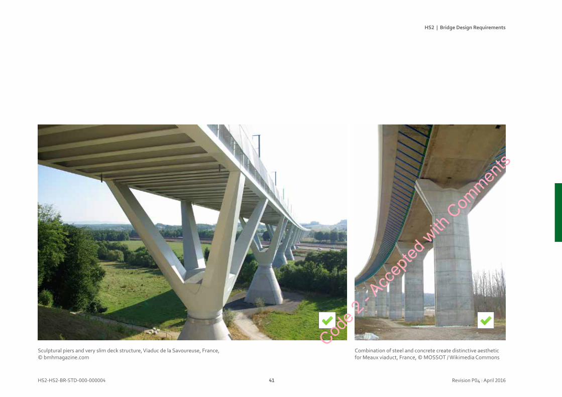
Sculptural piers and very slim deck structure, Viaduc de la Savoureuse, France,© bmhmagazine.com
Combination of steel and concrete create distinctive aesthetic for Meaux viaduct, France, © MOSSOT / Wikimedia Commons
Code 2
- Acc
epted
with
Com
ments
HS2 | Bridge Design Requirements
HS2-HS2-BR-STD-000-000004 42 Revision P04 : April 2016
PedestrianunderpassesBridgedesignscenarios
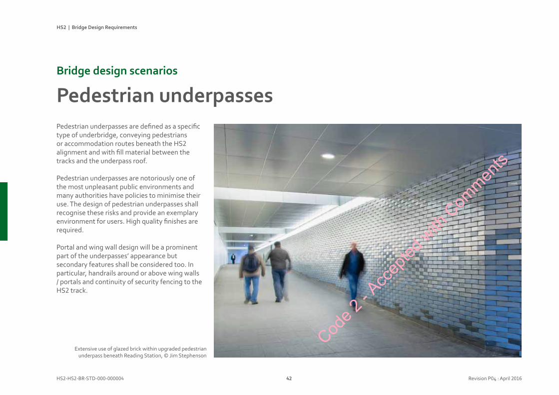
Pedestrian underpasses are defined as a specific type of underbridge, conveying pedestrians or accommodation routes beneath the HS2 alignment and with fill material between the tracks and the underpass roof.
Pedestrian underpasses are notoriously one of the most unpleasant public environments and many authorities have policies to minimise their use. The design of pedestrian underpasses shall recognise these risks and provide an exemplary environment for users. High quality finishes are required.
Portal and wing wall design will be a prominent part of the underpasses’ appearance but secondary features shall be considered too. In particular, handrails around or above wing walls / portals and continuity of security fencing to the HS2 track.
Extensive use of glazed brick within upgraded pedestrian underpass beneath Reading Station, © Jim Stephenson
Code 2
- Acc
epted
with
Com
ments

HS2 | Bridge Design Requirements
HS2-HS2-BR-STD-000-000004 43 Revision P04 : April 2016
Designconsiderations
• Underpass cross-sections have a significant impact on user experience. Although minimum cross section sizes are defined, consideration should be given to more generous dimensions, particularly for long structures.
• A rectangular cross-section is best suited to users’ needs, arched cross sections are not preferred.
• Approach routes and plan geometry have a significant impact upon pedestrian safety. Clear lines of sight are important for pedestrians to feel confident that they will not be vulnerable. Use of mirrors to provide views around blind corners should be considered as a failure. This applies to fenced approaches as well as to underpasses.
• Separate ‘lanes’ for pedestrians and cyclists are unlikely to be effective, with potential for conflict at crossing points. An environment that is clearly shared is more likely to be understood by all users.
• Barriers to prevent vehicle access may be required in some locations. These need to be carefully designed if they are to prevent motorcycle access but not disrupt cyclist use. Consider landscape design and use of street furniture to discourage motorcycle use.
• Frequency and intensity of use shall be established to define maintenance requirements, e.g. commuter route v country footpath v local farm access.
• Consider vandalism risks, including litter, graffiti, malicious damage (e.g. to luminaires), theft (e.g. of surface mounted metal components) and arson.
• Large areas of plain finishes can be a more attractive target for graffiti. Higher quality or patterned finishes shall be considered, especially in more intensely used locations. Finish options could include: brick, glazed brick, ceramic tile, self-finished metals.
• Wall finishes are likely to suffer from graffiti. They shall be easy to clean. Exposed concrete should have an anti-graffiti coating.
• Structural water-proofing will affect the quality of the pedestrian environment. Water penetration and staining of finishes shall be prevented. Special attention should be paid to any construction or movement joints.
• Floor finishes shall be compatible with the surrounding footpaths. They shall provide good slip resistance and be well drained, with consideration to mud or ice build-up. (Note that most underpasses will incorporate buried services routes, including piped drainage).
• In rural locations, it is assumed that footpaths and underpasses will not be lit at night. In urban locations illumination levels shall be carefully considered to avoid strong contrast or glare when moving between underpasses and surrounding environments.Cod
e 2 - A
ccep
ted w
ith C
ommen
ts
HS2 | Bridge Design Requirements
HS2-HS2-BR-STD-000-000004 44 Revision P04 : April 2016
PedestrianunderpassesBridgedesignscenarios
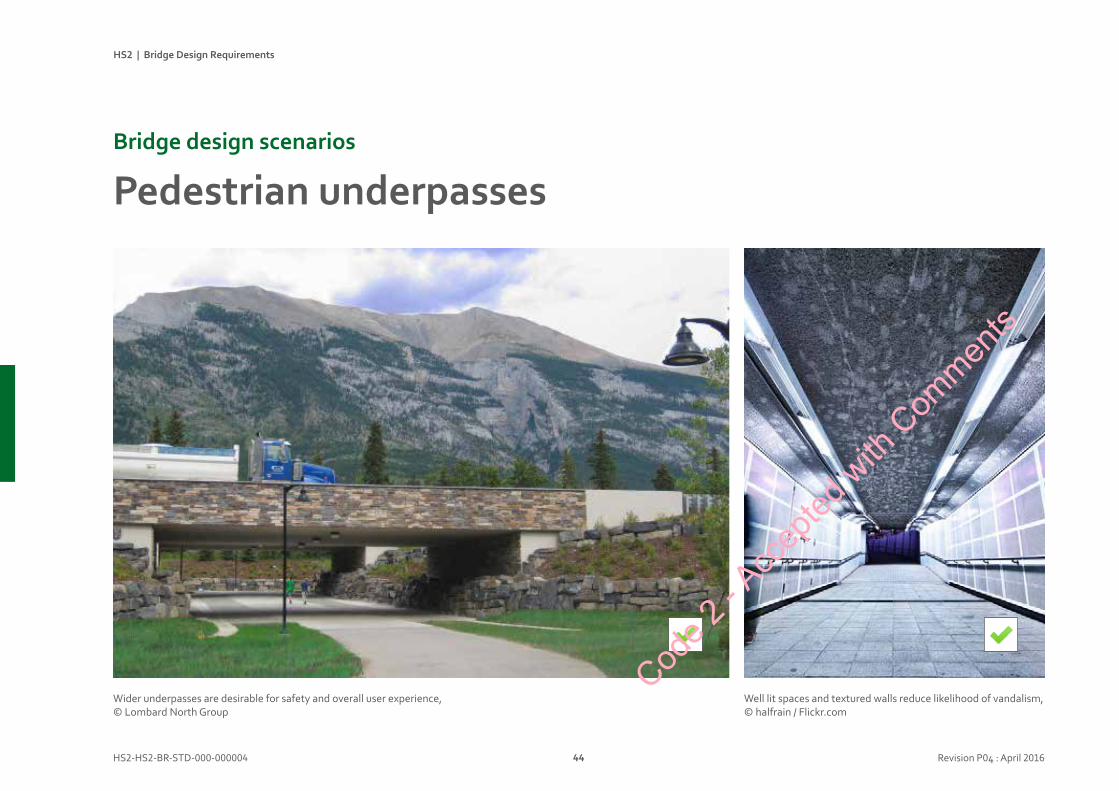
Wider underpasses are desirable for safety and overall user experience,© Lombard North Group
Well lit spaces and textured walls reduce likelihood of vandalism, © halfrain / Flickr.com
Code 2
- Acc
epted
with
Com
ments

HS2 | Bridge Design Requirements
HS2-HS2-BR-STD-000-000004 45 Revision P04 : April 2016
Clear lines of sight increase sense of safety for pedestrians, © mick lobb / Wikimedia Commons
Blind corners and graffiti: typical underpass problems to be considered in design proposals, © Szilas / Wikimedia Commons
Patterned tiles create bright environment and deter graffiti in Elephant and Castle underpass, © classicalmusicmagazine.org
X
Code 2
- Acc
epted
with
Com
ments
HS2 | Bridge Design Requirements
HS2-HS2-BR-STD-000-000004 46 Revision P04 : April 2016
OverbridgesBridgedesignscenarios
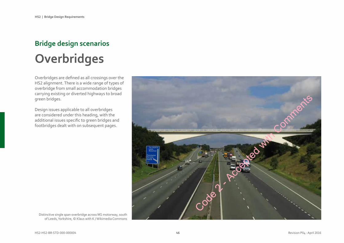
Overbridges are defined as all crossings over the HS2 alignment. There is a wide range of types of overbridge from small accommodation bridges carrying existing or diverted highways to broad green bridges.
Design issues applicable to all overbridges are considered under this heading, with the additional issues specific to green bridges and footbridges dealt with on subsequent pages.
Distinctive single span overbridge across M1 motorway, south of Leeds, Yorkshire, © Klaus with K / Wikimedia Commons
Code 2
- Acc
epted
with
Com
ments

HS2 | Bridge Design Requirements
HS2-HS2-BR-STD-000-000004 47 Revision P04 : April 2016
Designconsiderations
• 3 span overbridges with bank seats shall be used in slope-sided cuttings to promote an open appearance.
• The appearance of single spans with substantial concrete or earth abutments / walls is not preferred, except for green bridges within green slope sided abutments.
• Long single span structures across slope-sided cuttings, between bank-seat abutments, are also acceptable.
• Across vertical sided (retaining wall) cuttings, single span structures are preferred.
• Where bearings are unavoidable, integral piers are preferred with bearings at abutments where access is easier and less disruptive to rail operations.
• In three span overbridges, the central span should larger than the side spans. The side spans should be equally sized.
• Where overbridges have more than three spans, the spans should be rationalised and made equal. Shorter spans are permitted at abutments.
• Leaf piers to support multi-beam decks are acceptable for 3 span overbridges.
• Elaborately ‘shaped’ sculptural piers are not appropriate for overbridges piers within HS2 railway cuttings.
Code 2
- Acc
epted
with
Com
ments

HS2 | Bridge Design Requirements
HS2-HS2-BR-STD-000-000004 48 Revision P04 : April 2016
OverbridgesBridgedesignscenarios
Large concrete abutments interrupt continuity of open slope sided cutting,© Grimshaw
3 span overbridge maintains continuity of cutting and significantly reduces visibleextent of concrete, © Grimshaw
X
Code 2
- Acc
epted
with
Com
ments

HS2 | Bridge Design Requirements
HS2-HS2-BR-STD-000-000004 49 Revision P04 : April 2016
3 span geometry preferred for typical highway and accommodation overbridges, © Grimshaw
Bank seat abutment maintains open continuity of cutting below overbridge, © Roads and Maritime Services NSW
Bold asymmetric overbridge design works with strongly with gradient of Snow Hill Lane crossing the M6, © David Humphreys
Code 2
- Acc
epted
with
Com
ments
HS2 | Bridge Design Requirements
HS2-HS2-BR-STD-000-000004 50 Revision P04 : April 2016
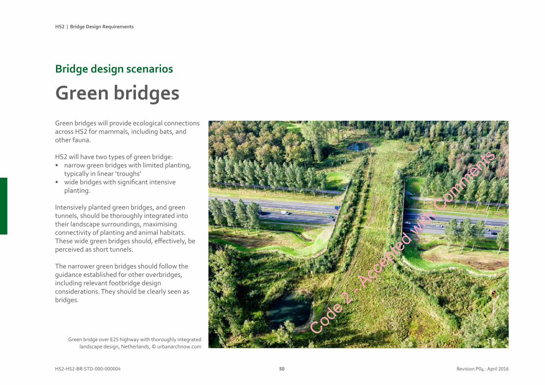
Green bridges will provide ecological connections across HS2 for mammals, including bats, and other fauna.
HS2 will have two types of green bridge:• narrow green bridges with limited planting,
typically in linear ‘troughs’• wide bridges with significant intensive
planting.
Intensively planted green bridges, and green tunnels, should be thoroughly integrated into their landscape surroundings, maximising connectivity of planting and animal habitats. These wide green bridges should, effectively, be perceived as short tunnels.
The narrower green bridges should follow the guidance established for other overbridges, including relevant footbridge design considerations. They should be clearly seen as bridges.
GreenbridgesBridgedesignscenarios
Green bridge over E25 highway with thoroughly integrated landscape design, Netherlands, © urbanarchnow.com
Code 2
- Acc
epted
with
Com
ments

HS2 | Bridge Design Requirements
HS2-HS2-BR-STD-000-000004 51 Revision P04 : April 2016
Designconsiderations
• The lightly planted green bridges, with hedge planting in linear troughs, should be treated like road overbridges, with 3 span structures.
• The intensively planted green bridges should be single span, recognising increased loads and the solidity of appearance that should complement the sense of this planting being in ‘solid’ earth.
• The single span length of intensively planted green bridges should be minimised with slope-sided earth embankments across the cutting leading up to the span.
• Adjacent slope angles should be matched and the junction between them radiussed to provide a smooth natural-looking transition.
• The “portals” for intensively planted green bridges should be coordinated as a family with tunnel and green tunnel portals, recognising their function to provide significant landscape continuity over the HS2 route.
• In rural locations, it is assumed that the footpaths passing over green bridges will not be lit at night.
• Green bridges shall have step free access. Steel or concrete ramps should be avoided in rural locations. Earthworks ramps should be designed to avoid the need for handrails and balustrades / guarding.
• Hard vertical abutment surfaces and retaining walls (e.g. concrete) are likely to be visually intrusive in rural locations and their use for green bridges shall be minimised and subject to specific justification in each location where they are proposed.
Code 2
- Acc
epted
with
Com
ments
HS2 | Bridge Design Requirements
HS2-HS2-BR-STD-000-000004 52 Revision P04 : April 2016
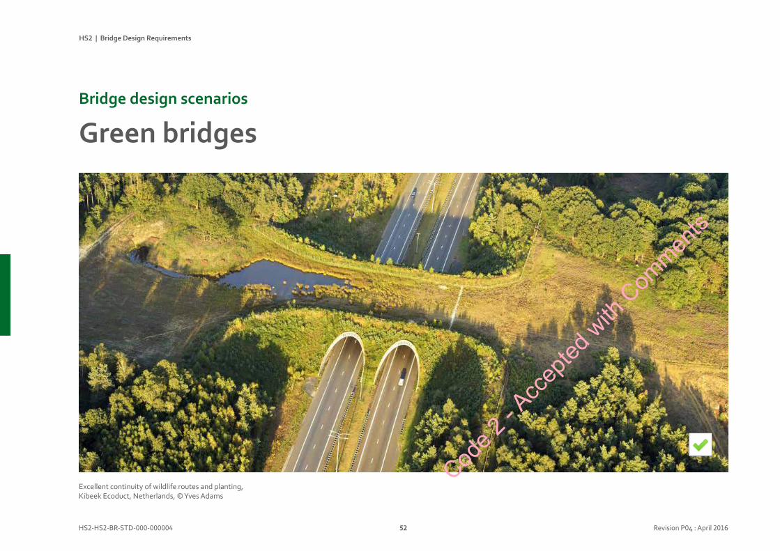
GreenbridgesBridgedesignscenarios
Excellent continuity of wildlife routes and planting, Kibeek Ecoduct, Netherlands, © Yves Adams
Code 2
- Acc
epted
with
Com
ments
HS2 | Bridge Design Requirements
HS2-HS2-BR-STD-000-000004 53 Revision P04 : April 2016
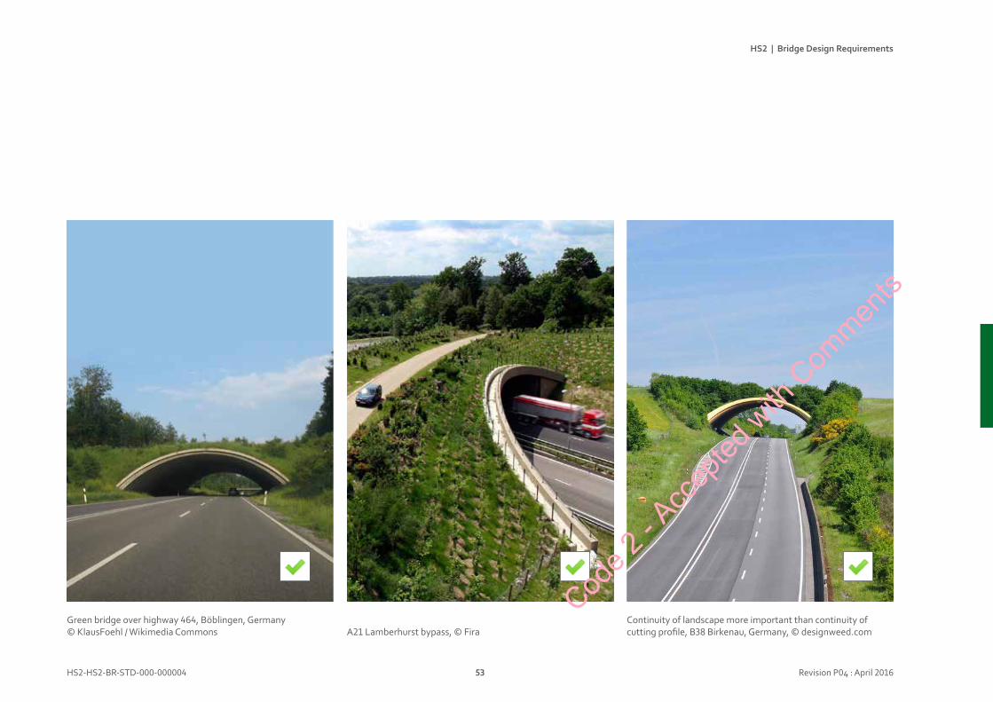
A21 Lamberhurst bypass, © FiraContinuity of landscape more important than continuity of cutting profile, B38 Birkenau, Germany, © designweed.com
Green bridge over highway 464, Böblingen, Germany © KlausFoehl / Wikimedia Commons
Code 2
- Acc
epted
with
Com
ments
HS2 | Bridge Design Requirements
HS2-HS2-BR-STD-000-000004 54 Revision P04 : April 2016
FootbridgesBridgedesignscenarios
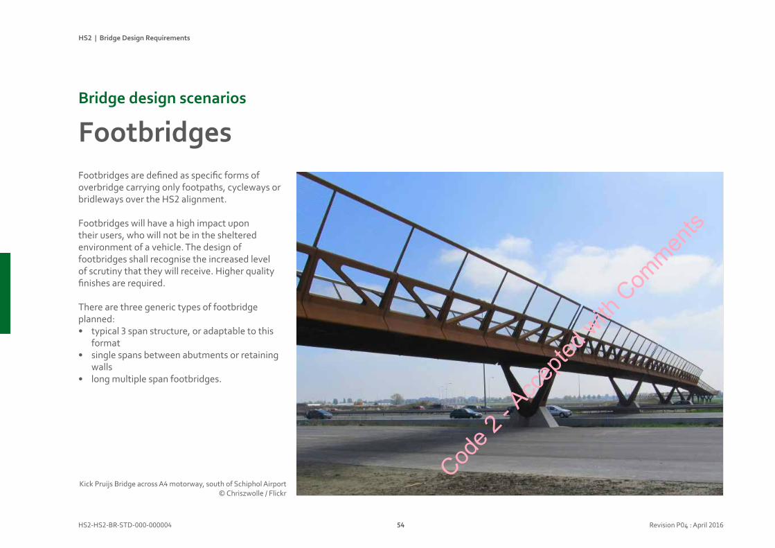
Footbridges are defined as specific forms of overbridge carrying only footpaths, cycleways or bridleways over the HS2 alignment.
Footbridges will have a high impact upon their users, who will not be in the sheltered environment of a vehicle. The design of footbridges shall recognise the increased level of scrutiny that they will receive. Higher quality finishes are required.
There are three generic types of footbridge planned: • typical 3 span structure, or adaptable to this
format• single spans between abutments or retaining
walls• long multiple span footbridges.
Kick Pruijs Bridge across A4 motorway, south of Schiphol Airport © Chriszwolle / Flickr
Code 2
- Acc
epted
with
Com
ments
HS2 | Bridge Design Requirements
HS2-HS2-BR-STD-000-000004 55 Revision P04 : April 2016
Designconsiderations
• Footbridge cross-sections have a significant impact on user experience. Although minimum cross section sizes are defined, consideration should be given to more generous dimensions, particularly for long structures.
• Footbridges shall have step free access. Steel or concrete approach ramps should be avoided in rural locations. Earthwork ramps should be designed to avoid the need for handrails and guarding.
• Approach routes and plan geometry have a significant impact upon pedestrian safety. Clear lines of sight are important for pedestrians to feel confident that they will not be vulnerable. Use of mirrors to provide views around blind corners should be considered as a failure. This applies to fenced approaches as well as to footbridges.
• In rural locations, it is assumed that footpaths and footbridges will not be lit at night.
• In urban locations illumination levels shall be carefully considered to avoid strong contrast or glare when moving between footbridges and surrounding environments.
• Continuous LED lighting, mounted within handrail profiles is preferred, to provide discrete and even illumination for footbridge decks. Light levels and light distribution shall be sufficient to identify the faces of other users.
• Separate ‘lanes’ for pedestrians and cyclists are unlikely to be effective, with potential for conflict at crossing points. An environment that is clearly shared is more likely to be understood by all users.
• Barriers to prevent vehicle access to footbridges may be required in some locations. These shall be carefully designed if they are to prevent motorcycle access but not disrupt cyclist use. Cod
e 2 - A
ccep
ted w
ith C
ommen
ts
HS2 | Bridge Design Requirements
HS2-HS2-BR-STD-000-000004 56 Revision P04 : April 2016
FootbridgesBridgedesignscenarios
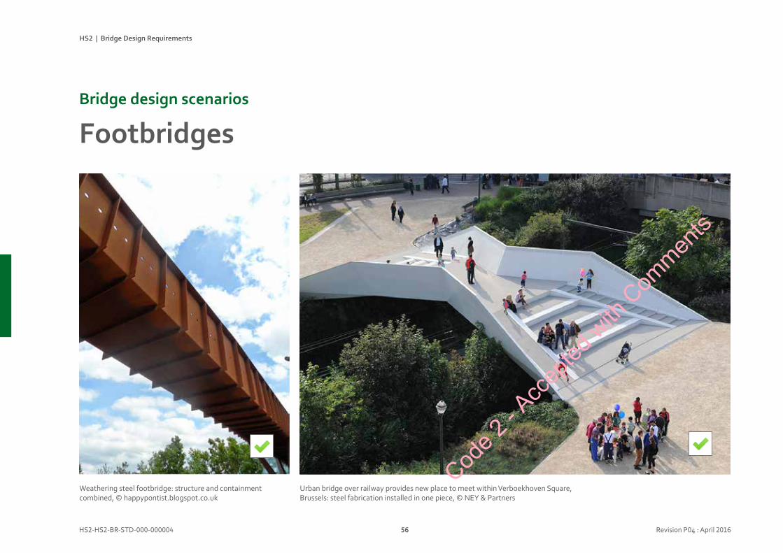
Urban bridge over railway provides new place to meet within Verboekhoven Square, Brussels: steel fabrication installed in one piece, © NEY & Partners
Weathering steel footbridge: structure and containment combined, © happypontist.blogspot.co.uk
Code 2
- Acc
epted
with
Com
ments
HS2 | Bridge Design Requirements
HS2-HS2-BR-STD-000-000004 57 Revision P04 : April 2016
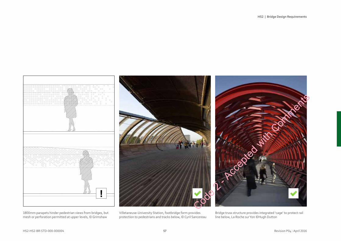
Villetaneuse-University Station, footbridge form provides protection to pedestrians and tracks below, © Cyril Sancereau
Bridge truss structure provides integrated ‘cage’ to protect rail line below, La Roche sur Yon ©Hugh Dutton
1800mm parapets hinder pedestrian views from bridges, but mesh or perforation permitted at upper levels, © Grimshaw
!Cod
e 2 - A
ccep
ted w
ith C
ommen
ts
Bridgedesignlibrary
Code 2
- Acc
epted
with
Com
ments
BridgedesignlibraryIntroduction 60
Landscape 62
Deckstructures 66
Piersandbearings 70
Parapets 74
Abutmentsandwalls 78
Materialsandmaintenance 82
Steelwork 86
Concrete 90
Rainwatermanagement 94
Servicesandrailsystems 98
Bridgedesignlibrary
Code 2
- Acc
epted
with
Com
ments
HS2 | Bridge Design Requirements
HS2-HS2-BR-STD-000-000004 60 Revision P05 : April 2016
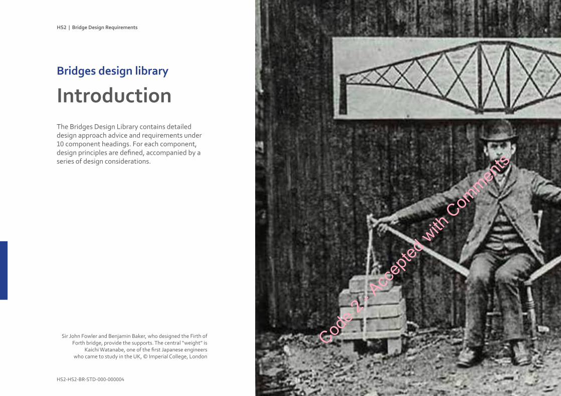
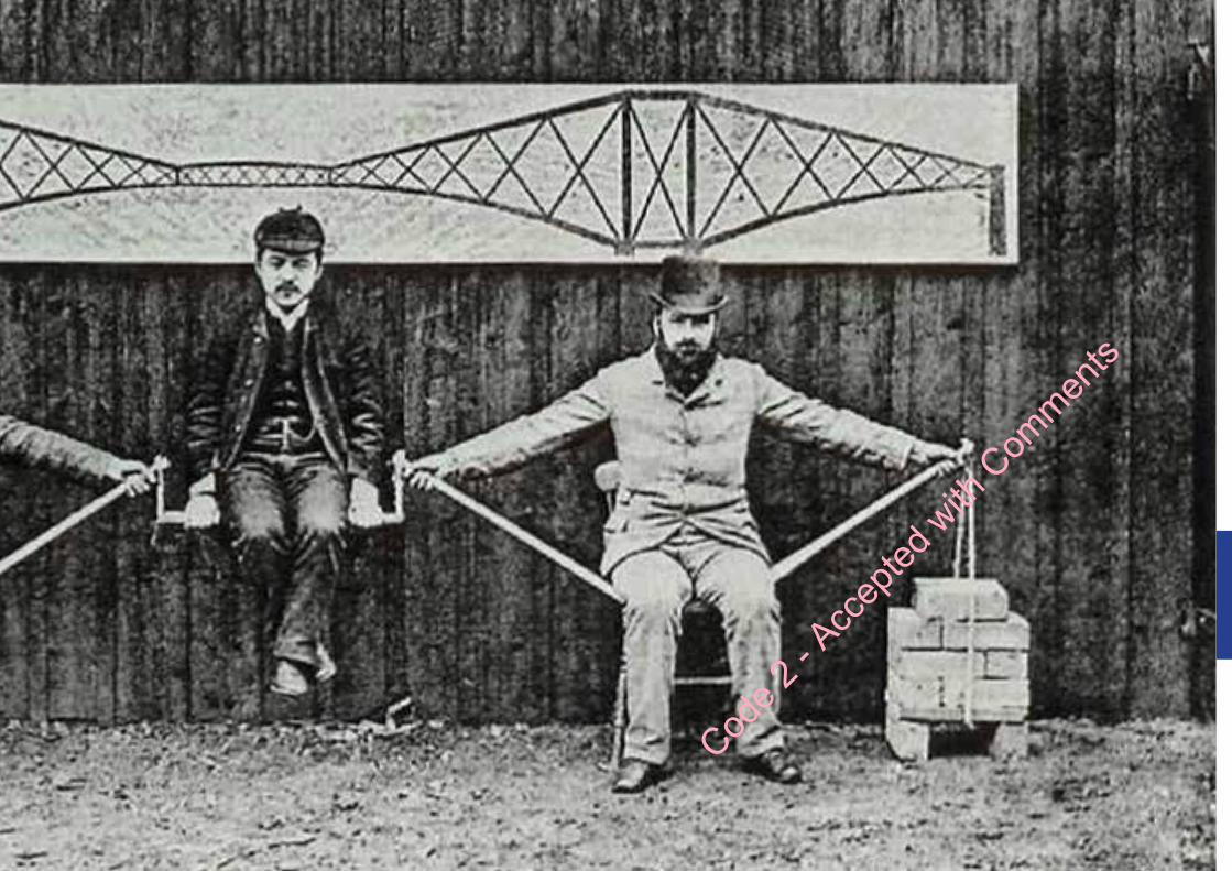
The Bridges Design Library contains detailed design approach advice and requirements under 10 component headings. For each component, design principles are defined, accompanied by a series of design considerations.
IntroductionBridgesdesignlibrary
Sir John Fowler and Benjamin Baker, who designed the Firth of Forth bridge, provide the supports. The central “weight” is
Kaichi Watanabe, one of the first Japanese engineerswho came to study in the UK, © Imperial College, London
Code 2
- Acc
epted
with
Com
ments
HS2 | Bridge Design Requirements
HS2-HS2-BR-STD-000-000004 61 Revision P05 : April 2016
Code 2
- Acc
epted
with
Com
ments
HS2 | Bridge Design Requirements
HS2-HS2-BR-STD-000-000004 62 Revision P04 : April 2016
DesignPrinciples
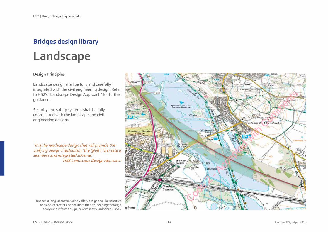
Landscape design shall be fully and carefully integrated with the civil engineering design. Refer to HS2’s “Landscape Design Approach” for further guidance.
Security and safety systems shall be fully coordinated with the landscape and civil engineering designs.
”It is the landscape design that will provide the unifying design mechanism (the ‘glue’) to create a seamless and integrated scheme.”
HS2 Landscape Design Approach
LandscapeBridgesdesignlibrary
Impact of long viaduct in Colne Valley: design shall be sensitive to place, character and nature of the site, needing thorough
analysis to inform design, © Grimshaw / Ordnance Survey
Code 2
- Acc
epted
with
Com
ments
HS2 | Bridge Design Requirements
HS2-HS2-BR-STD-000-000004 63 Revision P04 : April 2016
Designconsiderations
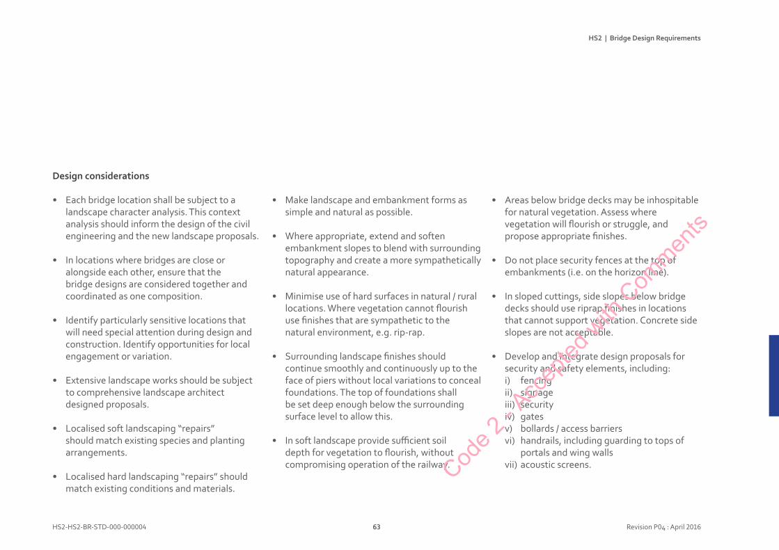
• Each bridge location shall be subject to a landscape character analysis. This context analysis should inform the design of the civil engineering and the new landscape proposals.
• In locations where bridges are close or alongside each other, ensure that the bridge designs are considered together and coordinated as one composition.
• Identify particularly sensitive locations that will need special attention during design and construction. Identify opportunities for local engagement or variation.
• Extensive landscape works should be subject to comprehensive landscape architect designed proposals.
• Localised soft landscaping “repairs” should match existing species and planting arrangements.
• Localised hard landscaping “repairs” should match existing conditions and materials.
• Make landscape and embankment forms as simple and natural as possible.
• Where appropriate, extend and soften embankment slopes to blend with surrounding topography and create a more sympathetically natural appearance.
• Minimise use of hard surfaces in natural / rural locations. Where vegetation cannot flourish use finishes that are sympathetic to the natural environment, e.g. rip-rap.
• Surrounding landscape finishes should continue smoothly and continuously up to the face of piers without local variations to conceal foundations. The top of foundations shall be set deep enough below the surrounding surface level to allow this.
• In soft landscape provide sufficient soil depth for vegetation to flourish, without compromising operation of the railway.
• Areas below bridge decks may be inhospitable for natural vegetation. Assess where vegetation will flourish or struggle, and propose appropriate finishes.
• Do not place security fences at the top of embankments (i.e. on the horizon line).
• In sloped cuttings, side slopes below bridge decks should use riprap finishes in locations that cannot support vegetation. Concrete side slopes are not acceptable.
• Develop and integrate design proposals for security and safety elements, including:i) fencingii) signageiii) securityiv) gatesv) bollards / access barriersvi) handrails, including guarding to tops of
portals and wing wallsvii) acoustic screens.Cod
e 2 - A
ccep
ted w
ith C
ommen
ts
HS2 | Bridge Design Requirements
HS2-HS2-BR-STD-000-000004 64 Revision P04 : April 2016
LandscapeBridgesdesignlibrary
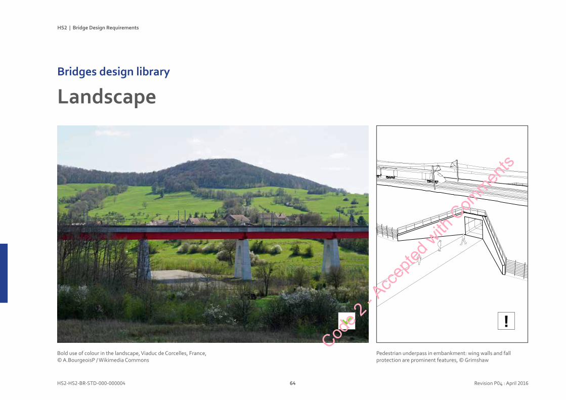
Bold use of colour in the landscape, Viaduc de Corcelles, France, © A.BourgeoisP / Wikimedia Commons
Pedestrian underpass in embankment: wing walls and fall protection are prominent features, © Grimshaw
!Cod
e 2 - A
ccep
ted w
ith C
ommen
ts
HS2 | Bridge Design Requirements
HS2-HS2-BR-STD-000-000004 65 Revision P04 : April 2016
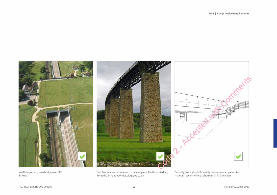
Security fence should fit neatly below parapet panels to maintain security line at abutments, © Grimshaw
Well integrated green bridge over HS1, © Arup
Soft landscape continues up to face of piers, Findhorn viaduct, Tomatin, © happypontist.blogspot.co.uk
Code 2
- Acc
epted
with
Com
ments

HS2 | Bridge Design Requirements
HS2-HS2-BR-STD-000-000004 66 Revision P04 : April 2016
DesignPrinciple
The form and detail of spanning structures shall be simple, continuous profiles modelled to minimise bulk and visual impact.
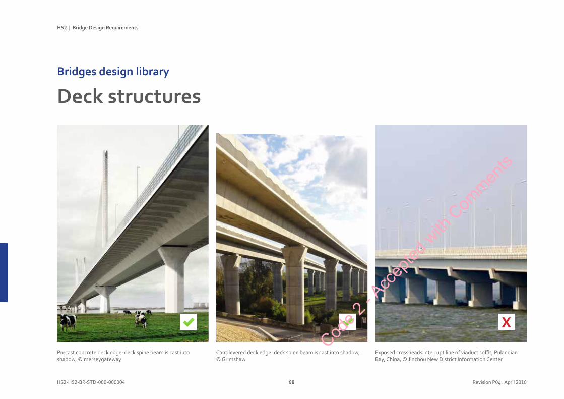
DeckstructuresBridgesdesignlibrary
Continuous deck edge: uninterrupted deck structure provides consistent clean profile within the landscape, © Yee Associates
Code 2
- Acc
epted
with
Com
ments
HS2 | Bridge Design Requirements
HS2-HS2-BR-STD-000-000004 67 Revision P04 : April 2016
Designconsiderations
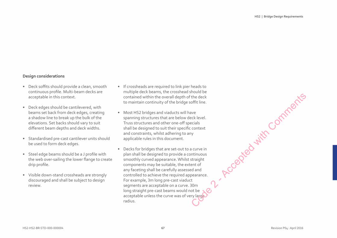
• Deck soffits should provide a clean, smooth continuous profile. Multi-beam decks are acceptable in this context.
• Deck edges should be cantilevered, with beams set back from deck edges, creating a shadow line to break up the bulk of the elevations. Set backs should vary to suit different beam depths and deck widths.
• Standardised pre-cast cantilever units should be used to form deck edges.
• Steel edge beams should be a J profile with the web over-sailing the lower flange to create drip profile.
• Visible down-stand crossheads are strongly discouraged and shall be subject to design review.
• If crossheads are required to link pier heads to multiple deck beams, the crosshead should be contained within the overall depth of the deck to maintain continuity of the bridge soffit line.
• Most HS2 bridges and viaducts will have spanning structures that are below deck level. Truss structures and other one-off specials shall be designed to suit their specific context and constraints, whilst adhering to any applicable rules in this document.
• Decks for bridges that are set-out to a curve in plan shall be designed to provide a continuous smoothly curved appearance. Whilst straight components may be suitable, the extent of any faceting shall be carefully assessed and controlled to achieve the required appearance. For example, 3m long pre-cast viaduct segments are acceptable on a curve. 30m long straight pre-cast beams would not be acceptable unless the curve was of very large radius. Cod
e 2 - A
ccep
ted w
ith C
ommen
ts
HS2 | Bridge Design Requirements
HS2-HS2-BR-STD-000-000004 68 Revision P04 : April 2016
DeckstructuresBridgesdesignlibrary
Cantilevered deck edge: deck spine beam is cast into shadow, © Grimshaw
Precast concrete deck edge: deck spine beam is cast into shadow, © merseygateway
X
Exposed crossheads interrupt line of viaduct soffit, Pulandian Bay, China, © Jinzhou New District Information Center
Code 2
- Acc
epted
with
Com
ments
HS2 | Bridge Design Requirements
HS2-HS2-BR-STD-000-000004 69 Revision P04 : April 2016
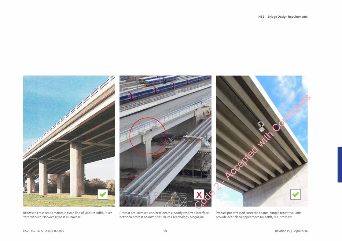
Precast pre-stressed concrete beams: poorly resolved interface between precast beams’ ends, © Rail Technology Magazine
Recessed crossheads maintain clean line of viaduct soffit, River Yare Viaduct, Norwich Bypass © Maunsell
Precast pre-stressed concrete beams: simple repetitive units provide neat clean appearance for soffit, © Grimshaw
X
Code 2
- Acc
epted
with
Com
ments
HS2 | Bridge Design Requirements
HS2-HS2-BR-STD-000-000004 70 Revision P04 : April 2016
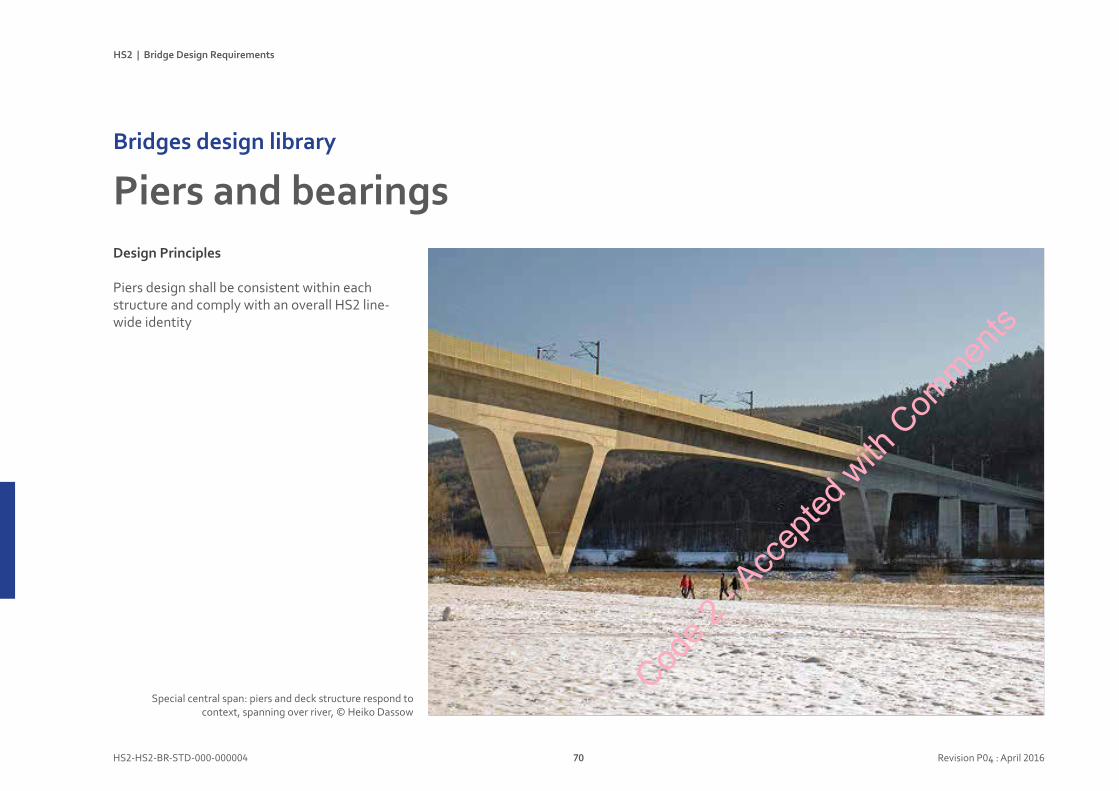
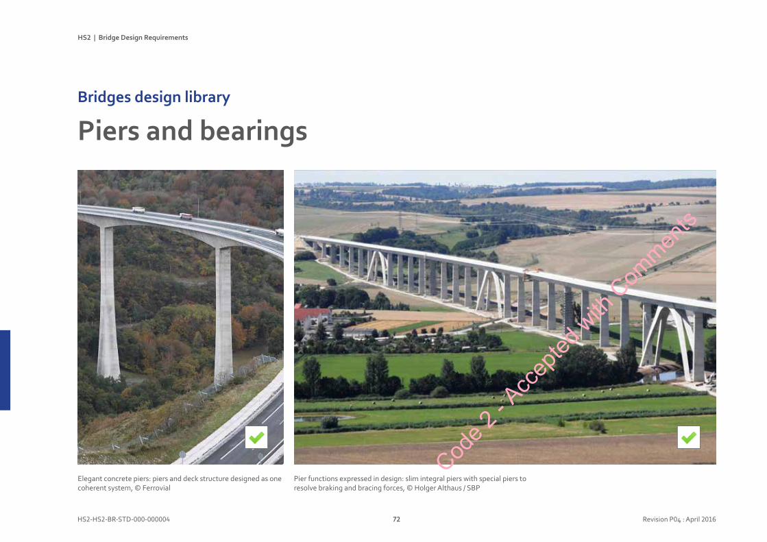
DesignPrinciples
Piers design shall be consistent within each structure and comply with an overall HS2 line-wide identity
PiersandbearingsBridgesdesignlibrary
Special central span: piers and deck structure respond to context, spanning over river, © Heiko Dassow
Code 2
- Acc
epted
with
Com
ments
HS2 | Bridge Design Requirements
HS2-HS2-BR-STD-000-000004 71 Revision P04 : April 2016
Designconsiderations
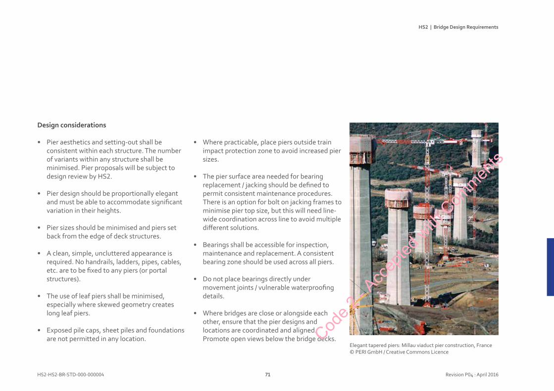
• Pier aesthetics and setting-out shall be consistent within each structure. The number of variants within any structure shall be minimised. Pier proposals will be subject to design review by HS2.
• Pier design should be proportionally elegant and must be able to accommodate significant variation in their heights.
• Pier sizes should be minimised and piers set back from the edge of deck structures.
• A clean, simple, uncluttered appearance is required. No handrails, ladders, pipes, cables, etc. are to be fixed to any piers (or portal structures).
• The use of leaf piers shall be minimised, especially where skewed geometry creates long leaf piers.
• Exposed pile caps, sheet piles and foundations are not permitted in any location.
• Where practicable, place piers outside train impact protection zone to avoid increased pier sizes.
• The pier surface area needed for bearing replacement / jacking should be defined to permit consistent maintenance procedures. There is an option for bolt on jacking frames to minimise pier top size, but this will need line-wide coordination across line to avoid multiple different solutions.
• Bearings shall be accessible for inspection, maintenance and replacement. A consistent bearing zone should be used across all piers.
• Do not place bearings directly under movement joints / vulnerable waterproofing details.
• Where bridges are close or alongside each other, ensure that the pier designs and locations are coordinated and aligned. Promote open views below the bridge decks.
Elegant tapered piers: Millau viaduct pier construction, France© PERI GmbH / Creative Commons Licence
Code 2
- Acc
epted
with
Com
ments
HS2 | Bridge Design Requirements
HS2-HS2-BR-STD-000-000004 72 Revision P04 : April 2016
PiersandbearingsBridgesdesignlibrary
Pier functions expressed in design: slim integral piers with special piers to resolve braking and bracing forces, © Holger Althaus / SBP
Elegant concrete piers: piers and deck structure designed as one coherent system, © Ferrovial
Code 2
- Acc
epted
with
Com
ments
HS2 | Bridge Design Requirements
HS2-HS2-BR-STD-000-000004 73 Revision P04 : April 2016
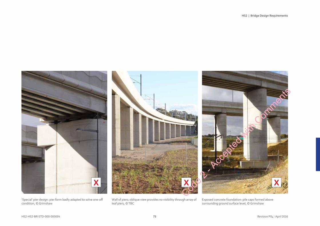
Wall of piers: oblique view provides no visibility through array of leaf piers, © TBC
‘Special’ pier design: pier form badly adapted to solve one-off condition, © Grimshaw
Exposed concrete foundation: pile caps formed above surrounding ground surface level, © Grimshaw
X XX
Code 2
- Acc
epted
with
Com
ments
HS2 | Bridge Design Requirements
HS2-HS2-BR-STD-000-000004 74 Revision P04 : April 2016
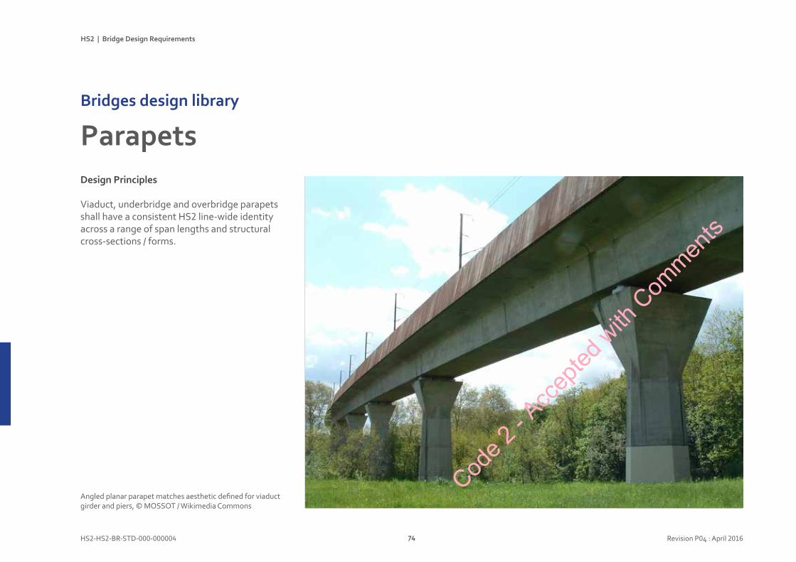
DesignPrinciples
Viaduct, underbridge and overbridge parapets shall have a consistent HS2 line-wide identity across a range of span lengths and structural cross-sections / forms.
ParapetsBridgesdesignlibrary
Angled planar parapet matches aesthetic defined for viaduct girder and piers, © MOSSOT / Wikimedia Commons
Code 2
- Acc
epted
with
Com
ments
HS2 | Bridge Design Requirements
HS2-HS2-BR-STD-000-000004 75 Revision P04 : April 2016
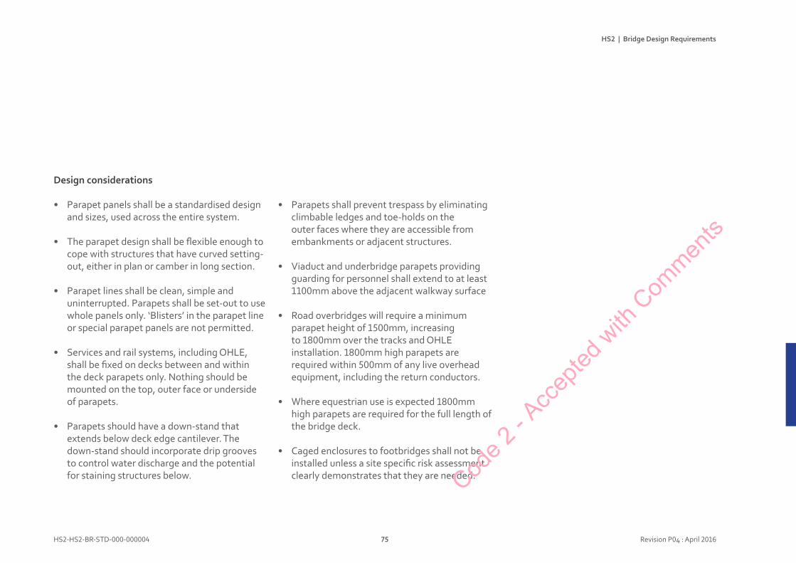
Designconsiderations
• Parapet panels shall be a standardised design and sizes, used across the entire system.
• The parapet design shall be flexible enough to cope with structures that have curved setting-out, either in plan or camber in long section.
• Parapet lines shall be clean, simple and uninterrupted. Parapets shall be set-out to use whole panels only. ‘Blisters’ in the parapet line or special parapet panels are not permitted.
• Services and rail systems, including OHLE, shall be fixed on decks between and within the deck parapets only. Nothing should be mounted on the top, outer face or underside of parapets.
• Parapets should have a down-stand that extends below deck edge cantilever. The down-stand should incorporate drip grooves to control water discharge and the potential for staining structures below.
• Parapets shall prevent trespass by eliminating climbable ledges and toe-holds on the outer faces where they are accessible from embankments or adjacent structures.
• Viaduct and underbridge parapets providing guarding for personnel shall extend to at least 1100mm above the adjacent walkway surface
• Road overbridges will require a minimum parapet height of 1500mm, increasing to 1800mm over the tracks and OHLE installation. 1800mm high parapets are required within 500mm of any live overhead equipment, including the return conductors.
• Where equestrian use is expected 1800mm high parapets are required for the full length of the bridge deck.
• Caged enclosures to footbridges shall not be installed unless a site specific risk assessment clearly demonstrates that they are needed.Cod
e 2 - A
ccep
ted w
ith C
ommen
ts

HS2 | Bridge Design Requirements
HS2-HS2-BR-STD-000-000004 76 Revision P04 : April 2016
PRECAST CONCRETE BEAM & SLAB
PRECAST SEGMENTAL
CONCRETE BOX
30
46
A - VIADUCTSFAMILY PREFERRED STRUCTURAL SOLUTION
STRUCTURAL VARIANTS
A1
PIER <10m
A2PIER >10m
DECK WIDTH [m]
31.0
18.0
41.5
4
1 TRACK 2 TRACK
4 TRACK
DECK WIDTH [m]
1 TRACK 2 TRACK
4 TRACK
8.5 m14.3 m
24.3 m
8.5 m14.3 m
24.3 m
F1
F2
I1
E1
STRUCTURAL SCOPING
MAX SPAN, LENGTH [m]
20 30
4.7
8.1
14.7
18.1
31.5
01
02
03
05
06
07
04
UP TO 20 m [U5 BEAM] UP TO 30 m [U10 BEAM]
01
02
03
04
05
06
07
MAX SPAN, LENGTH [m]
30 46
8.5
10.4
14.2
16.1
45.6
UP TO 30 m [MULTI GIRDER DECK] ABOVE 30 m [LADDER BEAM DECK]
08
09
10
11
12
13
14
08
09
10
11
12
13
14
9.1 m
11.3
14.3
8.5
12.3
14.9
20.2
6.2 m
9.5 m
14.3 m
6.2 m
9.5m
14.3 m
31.0 m
G1
G2
FAMILY PREFERRED STRUCTURAL SOLUTION STRUCTURAL VARIANTS
G - ROAD OVERBRIDGES
PRECAST PRESTRESSED CONCRETE BEAMS
STEEL COMPOSITE MULTIBEAM DECK
STEEL COMPOSITE LADDER BEAM DECK
SPAN <30mSKEW <30 o
SPAN >30m SKEW >30 o
A1
A2
STRUCTURAL SCOPING
ParapetsBridgesdesignlibrary
X
Closer view of H4a barriers plus pedestrian barrier and additional higher protection above track / OHLE, © Grimshaw
Pre-cast concrete parapets have potential to contribute toa line-wide identity for HS2, © Grimshaw
X
Visual impact of H4a barriers plus pedestrian barrier and additional higher protection above track / OHLE, © Grimshaw
Code 2
- Acc
epted
with
Com
ments
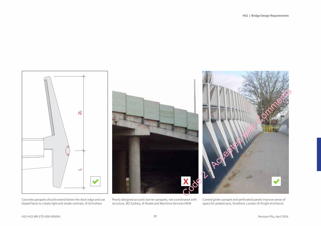
HS2 | Bridge Design Requirements
HS2-HS2-BR-STD-000-000004 77 Revision P04: April 2016
the line of the parapet on the bridge over Woronora river at sutherland is an important bridge element. it is sharp, smooth, catches the light, helps provide shadow and unifies the structure.
in some circumstances where the parapet is proportionally too deep, a crease line or kink can help visually break down the apparent depth as on this pacific highway bridge at Banora point. the parapet is on a continuous curve to avoid the faceted appearance of the super t girders.
the lack of a well designed parapet creates a visually confusing superstructure as in this bridge over the m2 motorway at Beecroft. this is an example of a poor aesthetic outcome.
the pArts SeCtion 4 49
X
Concrete parapets should extend below the deck edge and use sloped faces to create light and shade contrast, © Grimshaw
Stratford City Bridge 1London, UK
The bridge forms part of the Athletes’ Village infrastructure, connecting the north end of the Stratford Olympic site with Waltham Forest and Leyton to the east.
The brief for the 35m span foot and cycle bridge is dominated by the requirements for rail safety above the Network Rail High Speed 1 line to the nearby Temple Mills Depot, which include minimal possession times for installation and maintenance and a varying parapet height of up to 3m.
The weathering steel structure maintains the familiar appearance
of other SCD bridges and the inclined mesh sides of the bridge follows a smooth vertical curve so the secure enclosure is an integral part of the form and contributes to a co-ordinated approach to a high quality public realm.
Planning consents were granted in January 2010 following extensive consultation with stakeholders including the Olympic Delivery Authority, London Borough of Waltham Forest, Transport for London, Network Rail and High Speed 1 (Channel Tunnel Rail Link).
Client: Lend LeaseArchitect: Knight ArchitectsConsulting Engineer: Arup
Programme: 2009-11
Canted girder parapet and perforated panels improve sense of space for pedestrians, Stratford, London © Knight Architects
2LL
Poorly designed acoustic barrier parapets, not coordinated with structure, M2 Sydney, © Roads and Maritime Services NSW
Code 2
- Acc
epted
with
Com
ments

HS2 | Bridge Design Requirements
HS2-HS2-BR-STD-000-000004 78 Revision P04 : April 2016
Designprinciple
HS2 makes extensive use of retaining walls, typically with retained heights exceeding 3m. In visually sensitive locations, especially rural ones, the visible extent of concrete walls and abutments shall be minimised, before considering cladding or screening.
AbutmentsandwallsBridgesdesignlibrary
Walled abutments can reduce the slender appearance of the bridge, block the flow of the landscape and confine views.
Reducing the abutments can create a more refined and better looking bridge. It does however increase the span and therefore depth of the beam.
Continuing the superstructure of the parapet above the abutment allows the shadow line to reduce the dominance of the abutment, and makes the bridge appear longer and more elegant.
Diagrams from ‘Bridge Aesthetics’ by the New South Wales Government, Australia, © Roads and Maritime Services NSW
Code 2
- Acc
epted
with
Com
ments

HS2 | Bridge Design Requirements
HS2-HS2-BR-STD-000-000004 79 Revision P04 : April 2016
Designconsiderations
• Minimise and avoid the use of vertical walls (including abutments, wing walls, side walls and retaining walls) in rural areas where they will be visible to the public: they are an alien element.
• Wing walls for viaduct abutments shall be parallel to the HS2 track alignment.
• Underbridge wing walls in embankments should be aligned at approximately 45 degrees so that a slope continues in front of the wing wall, minimising the overall length of wall.
• Bank seats (or their appearance) should be used for overbridges across slope-sided cuttings, in preference to visible full height concrete abutments.
• Minimise hard landscape finishes around abutments in rural areas. Use vegetated earth slopes. Use riprap in areas where planting will not thrive.
• In urban areas with hard landscaping, vertical faces for abutments and wing walls are preferred.
• Design and detailing shall manage water flow to prevent leakage from drainage behind walls and prevent staining or poor weathering of front faces.
• Assess visibility from publicly accessible locations. There will be locations where cutting walls are visible, especially the upper most parts, walls near the ends of cuttings and in areas where the land form affords views into the cutting. In these locations, a higher quality finish shall be required.
• Assess impact upon passenger experience. High speed glimpses of walls through carriage windows will not be a concern. However, for retaining walls alongside a station and other locations easily visible to passengers, the quality of construction, finish and appearance shall be important.
• Design pre-cast wall units’ size, shape and finish to be in proportion and scale to the whole structure and sympathetic to the location.
• Details at edges / interfaces will have a considerable impact upon appearance and weathering. Careful coordinate copings, handrails, connections to other construction, access / inspection hatches, etc.
Code 2
- Acc
epted
with
Com
ments
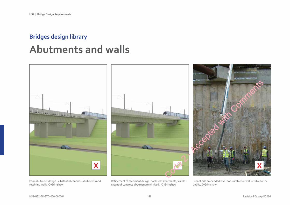
HS2 | Bridge Design Requirements
HS2-HS2-BR-STD-000-000004 80 Revision P04 : April 2016
AbutmentsandwallsBridgesdesignlibrary
Secant pile embedded wall: not suitable for walls visible to the public, © Grimshaw
X
Poor abutment design: substantial concrete abutments and retaining walls, © Grimshaw
X
Refinement of abutment design: bank seat abutments, visible extent of concrete abutment minimised., © Grimshaw
Code 2
- Acc
epted
with
Com
ments
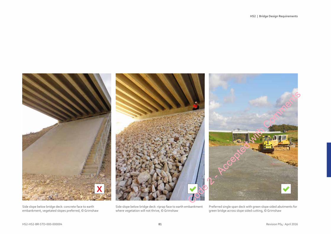
HS2 | Bridge Design Requirements
HS2-HS2-BR-STD-000-000004 81 Revision P04 : April 2016
X
Side slope below bridge deck: riprap face to earth embankment where vegetation will not thrive, © Grimshaw
Side slope below bridge deck: concrete face to earth embankment, vegetated slopes preferred, © Grimshaw
Preferred single span deck with green slope sided abutments for green bridge across slope sided cutting, © Grimshaw
Code 2
- Acc
epted
with
Com
ments
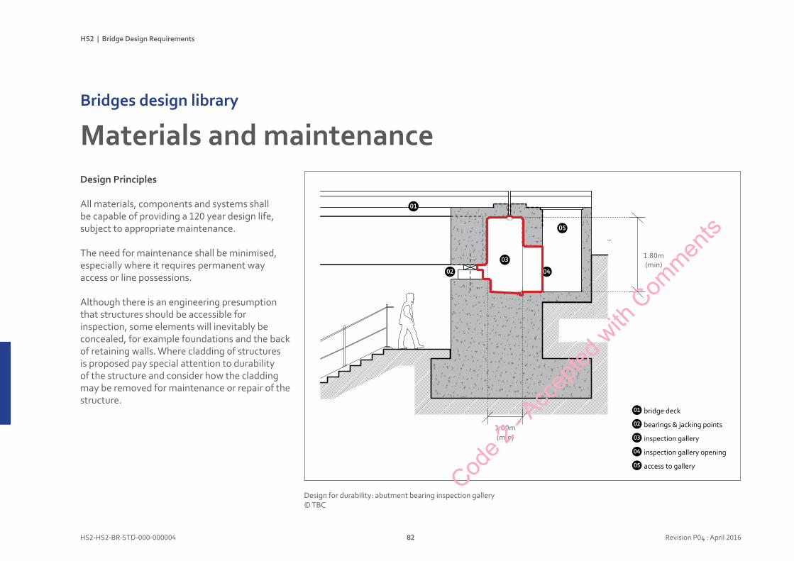
HS2 | Bridge Design Requirements
HS2-HS2-BR-STD-000-000004 82 Revision P04 : April 2016
DesignPrinciples
All materials, components and systems shall be capable of providing a 120 year design life, subject to appropriate maintenance.
The need for maintenance shall be minimised, especially where it requires permanent way access or line possessions.
Although there is an engineering presumption that structures should be accessible for inspection, some elements will inevitably be concealed, for example foundations and the back of retaining walls. Where cladding of structures is proposed pay special attention to durability of the structure and consider how the cladding may be removed for maintenance or repair of the structure.
MaterialsandmaintenanceBridgesdesignlibrary
01
02
03
04
05
bridge deck
bearings & jacking points
inspection gallery
inspection gallery opening
access to gallery
Design for durability: abutment bearing inspection gallery © TBC
1.80m(min)
01
03
02
05
04
1.00m (min)
Code 2
- Acc
epted
with
Com
ments
HS2 | Bridge Design Requirements
HS2-HS2-BR-STD-000-000004 83 Revision P04 : April 2016
Designconsiderations
• Self-finished materials are strongly preferred. If coatings are used, very long life factory applied coatings (e.g. galvanising, anodising) are preferred to paint, powder coating, etc.
• Do not use paint finishes where access for re-painting requires permanent way possessions.
• On-site cutting or drilling of coated (galvanised, painted, etc.) components is not permitted: this will require careful detailed design and fabrication.
• Movement joints should be minimised. Where they are essential, they should be properly detailed to be concealed or coordinated with the geometry and appearance of the whole structure.
• Detail structures, including piers and abutments, to avoid creating ledges which could be used by roosting birds or for climbing the structure.
• Netting or wires shall not be relied upon to prevent bird perching. They have poor durability, collect dirt and impede maintenance access.
• Deck finishes should be compatible with the surrounding environment. They shall provide good slip resistance and be well drained, with consideration to mud or ice build-up: overbridges are often more vulnerable to ice formation than their surrounding environments. Deck finishes should also be resistant to small scale fires.
• Large areas of plain finishes may suffer from graffiti: they shall be easy to clean. Consider anti-graffiti coatings for concrete, but there shall not affect the concrete’s appearance. Higher quality finishes should be considered in intensely used locations.
• Assess and mitigate vandalism risks including litter, graffiti, malicious damage (e.g. to luminaires), theft (e.g. of metal components) and arson.
• Integrate design of secure access to bearing locations / abutments for inspection and maintenance. Maintenance access routes, steps and handrails should be included in the designs.
• Where exposed concrete finishes are not acceptable, consider: i) masonry cladding (brick, block or stone) ii) other cladding (timber, metal, mesh, etc.) iii) screening with vegetation.
bridge deck
bearings & jacking points
inspection gallery
inspection gallery opening
access to gallery
Code 2
- Acc
epted
with
Com
ments
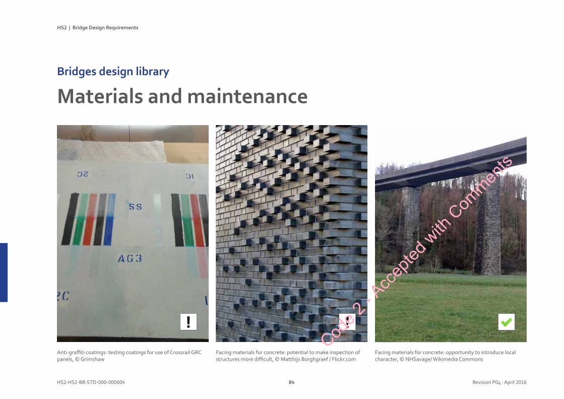
HS2 | Bridge Design Requirements
HS2-HS2-BR-STD-000-000004 84 Revision P04 : April 2016
!
MaterialsandmaintenanceBridgesdesignlibrary
!
Anti-graffiti coatings: testing coatings for use of Crossrail GRC panels, © Grimshaw
Facing materials for concrete: opportunity to introduce local character, © NHSavage/ Wikimedia Commons
Facing materials for concrete: potential to make inspection of structures more difficult, © Matthijs Borghgraef / Flickr.com
Code 2
- Acc
epted
with
Com
ments
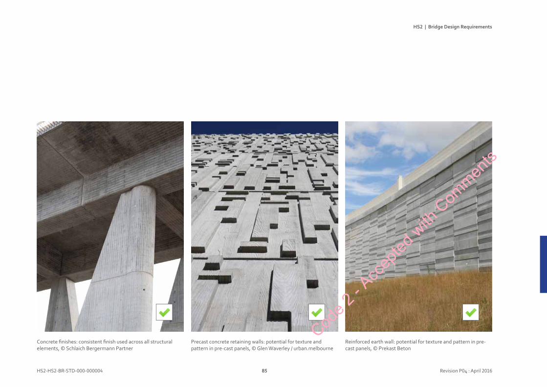
HS2 | Bridge Design Requirements
HS2-HS2-BR-STD-000-000004 85 Revision P04 : April 2016
Concrete finishes: consistent finish used across all structural elements, © Schlaich Bergermann Partner
Reinforced earth wall: potential for texture and pattern in pre-cast panels, © Prekast Beton
Precast concrete retaining walls: potential for texture and pattern in pre-cast panels, © Glen Waverley / urban.melbourne
Code 2
- Acc
epted
with
Com
ments
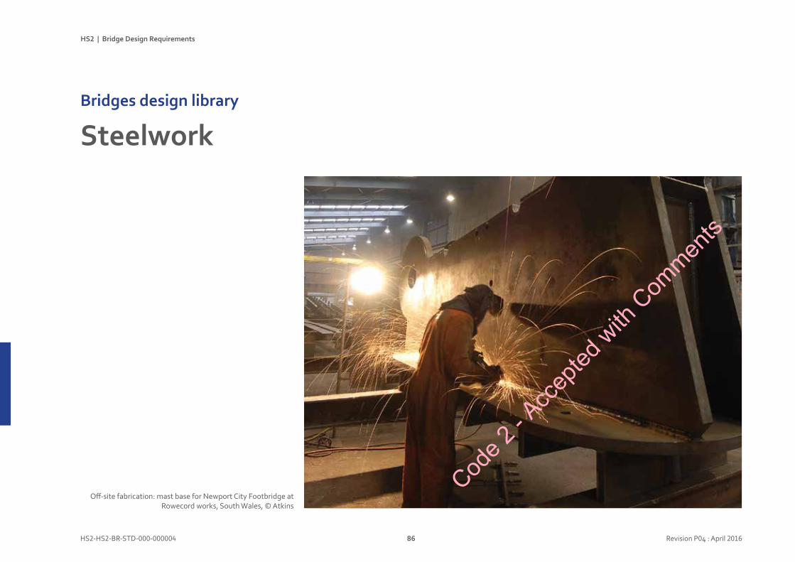
HS2 | Bridge Design Requirements
HS2-HS2-BR-STD-000-000004 86 Revision P04 : April 2016
SteelworkBridgesdesignlibrary
Off-site fabrication: mast base for Newport City Footbridge at Rowecord works, South Wales, © Atkins
Code 2
- Acc
epted
with
Com
ments
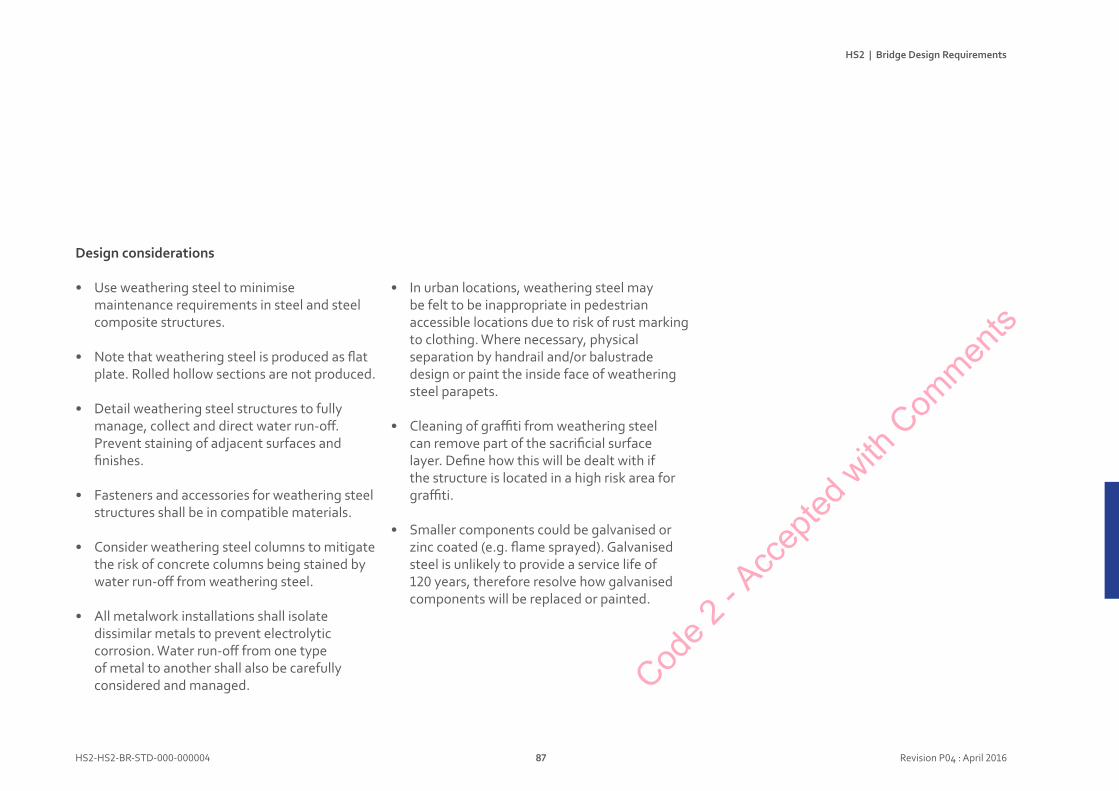
HS2 | Bridge Design Requirements
HS2-HS2-BR-STD-000-000004 87 Revision P04 : April 2016
Designconsiderations
• Use weathering steel to minimise maintenance requirements in steel and steel composite structures.
• Note that weathering steel is produced as flat plate. Rolled hollow sections are not produced.
• Detail weathering steel structures to fully manage, collect and direct water run-off. Prevent staining of adjacent surfaces and finishes.
• Fasteners and accessories for weathering steel structures shall be in compatible materials.
• Consider weathering steel columns to mitigate the risk of concrete columns being stained by water run-off from weathering steel.
• All metalwork installations shall isolate dissimilar metals to prevent electrolytic corrosion. Water run-off from one type of metal to another shall also be carefully considered and managed.
• In urban locations, weathering steel may be felt to be inappropriate in pedestrian accessible locations due to risk of rust marking to clothing. Where necessary, physical separation by handrail and/or balustrade design or paint the inside face of weathering steel parapets.
• Cleaning of graffiti from weathering steel can remove part of the sacrificial surface layer. Define how this will be dealt with if the structure is located in a high risk area for graffiti.
• Smaller components could be galvanised or zinc coated (e.g. flame sprayed). Galvanised steel is unlikely to provide a service life of 120 years, therefore resolve how galvanised components will be replaced or painted.
Code 2
- Acc
epted
with
Com
ments
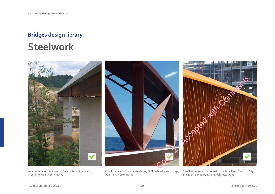
HS2 | Bridge Design Requirements
HS2-HS2-BR-STD-000-000004 88 Revision P04 : April 2016
SteelworkBridgesdesignlibrary
Stratford City Bridge 14London, UK
Knight Architects has enjoyed a leading role in the aesthetic design of the infrastructure for the £4bn Stratford City development in East London, including new pedestrian and cycle bridges of 26m, 35m 39m and 57m spans.
This major project will see the regeneration of 73ha of inner city land adjacent to the Olympic Park. Set above the extensive network of existing railway infrastructure, the projects must provide consistency in appearance, quality and safety.
Bridge 14 is a 6m-wide pedestrian and cycle bridge with a single span of 57m across railway lines with
overhead line electrification. One of the key challenges was reconciling the stringent security demands of Network Rail with the equally high expectations of the planners for an excellent pedestrian environment.
The 1.8m deep structural beam demanded by the span is used to provide the tall safety parapet, with the inner face of each beam clad in a backlit stainless steel mesh. The profile of the multiple web stiffeners on the outer faces of the beam constantly varies from end to end of the bridge, realising a virtual wave pattern in the south facing structure.
Client: Stratford City Developments Ltd (Westfield Shoppingtowns Ltd)Architect: Knight ArchitectsConsultants: Arup / PinnigerContractor’s Team: Morgan Est / Butterley / Benaim Scott Wilson
Completion: 2009
Crisply detailed structural steelwork, St Elmo breakwater bridge, Valetta, © Hector Beade
Weathering steel deck beams: Paint finish not required, © Commonwealth of Kentucky
Steel has potential for dramatic structural form, Stratford City Bridge 14, London © Knight Architects / Arup
Code 2
- Acc
epted
with
Com
ments

HS2 | Bridge Design Requirements
HS2-HS2-BR-STD-000-000004 89 Revision P04 : April 2016
X
Weathering steel column: form controls and directs rainwater run-off, © happypontist.blogspot.co.uk
Stained concrete pier: uncontrolled water run-off from weathering steel beam, © Z22 / Wikimedia Commons
Weathering steel footbridge: projecting handrail protects pedestrians from rusty surface, © Xavier Font / Dezeen.com
Code 2
- Acc
epted
with
Com
ments
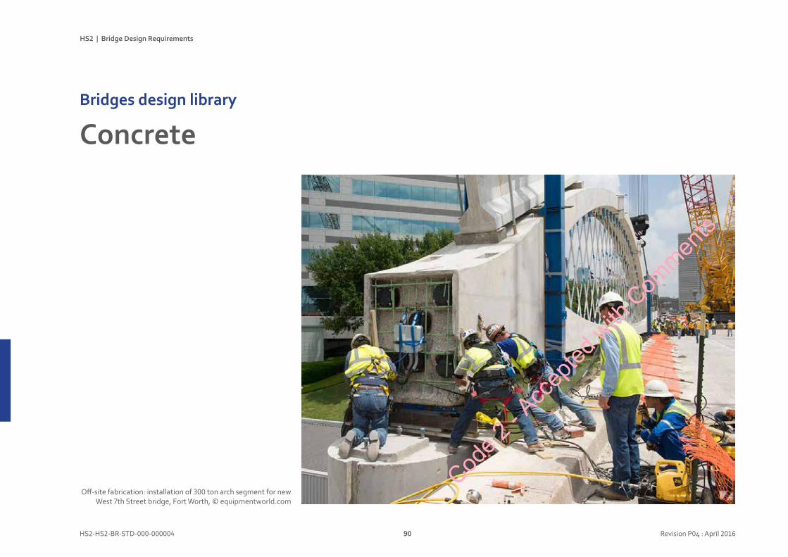
HS2 | Bridge Design Requirements
HS2-HS2-BR-STD-000-000004 90 Revision P04 : April 2016
ConcreteBridgesdesignlibrary
Off-site fabrication: installation of 300 ton arch segment for new West 7th Street bridge, Fort Worth, © equipmentworld.com
Code 2
- Acc
epted
with
Com
ments
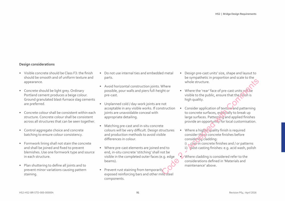
HS2 | Bridge Design Requirements
HS2-HS2-BR-STD-000-000004 91 Revision P04 : April 2016
Designconsiderations
• Visible concrete should be Class F3: the finish should be smooth and of uniform texture and appearance.
• Concrete should be light grey. Ordinary Portland cement produces a beige colour. Ground granulated blast-furnace slag cements are preferred.
• Concrete colour shall be consistent within each structure. Concrete colour shall be consistent across all structures that can be seen together.
• Control aggregate choice and concrete batching to ensure colour consistency.
• Formwork lining shall not stain the concrete and shall be joined and fixed to prevent blemishes. Use one formwork type and source in each structure.
• Plan shuttering to define all joints and to prevent minor variations causing pattern staining.
• Do not use internal ties and embedded metal parts.
• Avoid horizontal construction joints. Where possible, pour walls and piers full-height or pre-cast.
• Unplanned cold / day-work joints are not acceptable in any visible works. If construction joints are unavoidable conceal with appropriate detailing.
• Matching pre-cast and in-situ concrete colours will be very difficult. Design structures and production methods to avoid visible differences in colour.
• Where pre-cast elements are joined end to end, in-situ concrete ‘stitching’ shall not be visible in the completed outer faces (e.g. edge beams).
• Prevent rust staining from temporarily exposed reinforcing bars and other mild steel components.
• Design pre-cast units’ size, shape and layout to be sympathetic in proportion and scale to the whole structure.
• Where the ‘rear’ face of pre-cast units will be visible to the public, ensure that the finish is high quality.
• Consider application of texture and patterning to concrete surfaces, especially to break up large surfaces. Patterning and applied finishes provide an opportunity for local customisation.
• Where a higher quality finish is required consider these concrete finishes before considering cladding:i) cast-in concrete finishes and / or patternsii) post-casting finishes: e.g. acid wash, polish
• Where cladding is considered refer to the considerations defined in ‘Materials and maintenance’ above.
Code 2
- Acc
epted
with
Com
ments
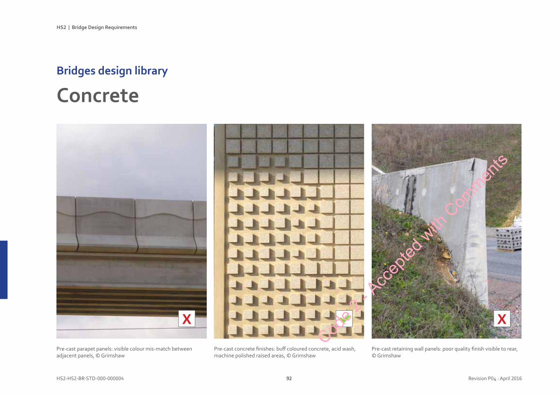
HS2 | Bridge Design Requirements
HS2-HS2-BR-STD-000-000004 92 Revision P04 : April 2016
ConcreteBridgesdesignlibrary
X
Pre-cast concrete finishes: buff coloured concrete, acid wash, machine polished raised areas, © Grimshaw
Pre-cast parapet panels: visible colour mis-match between adjacent panels, © Grimshaw
Pre-cast retaining wall panels: poor quality finish visible to rear, © Grimshaw
X
Code 2
- Acc
epted
with
Com
ments
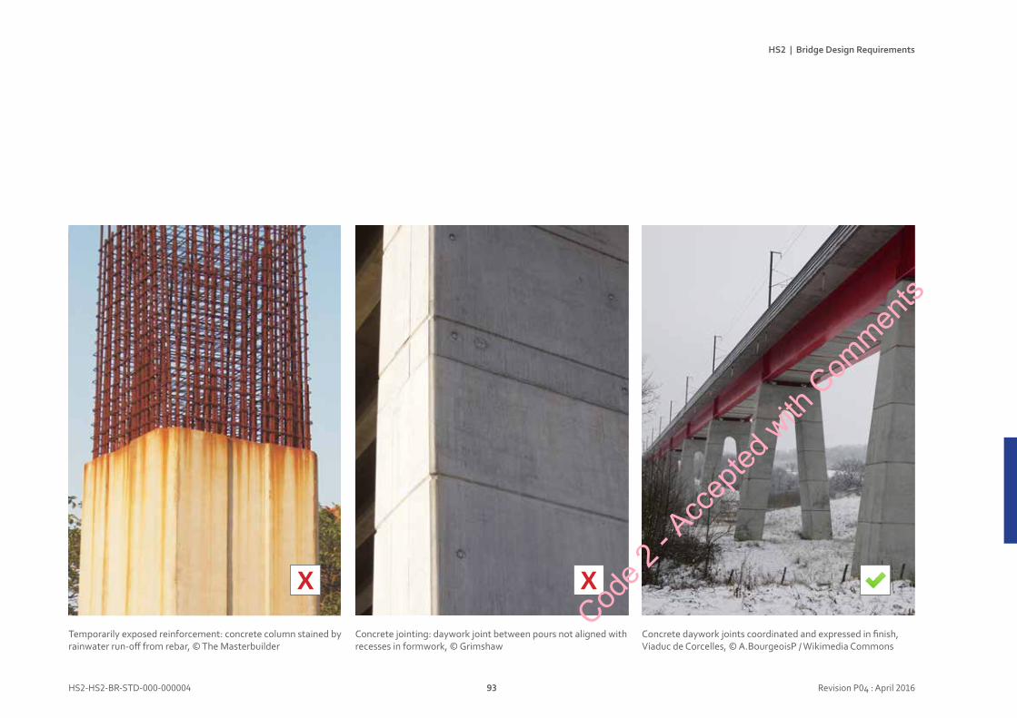
HS2 | Bridge Design Requirements
HS2-HS2-BR-STD-000-000004 93 Revision P04 : April 2016
X
Concrete jointing: daywork joint between pours not aligned with recesses in formwork, © Grimshaw
Temporarily exposed reinforcement: concrete column stained by rainwater run-off from rebar, © The Masterbuilder
Concrete daywork joints coordinated and expressed in finish, Viaduc de Corcelles, © A.BourgeoisP / Wikimedia Commons
XCod
e 2 - A
ccep
ted w
ith C
ommen
ts
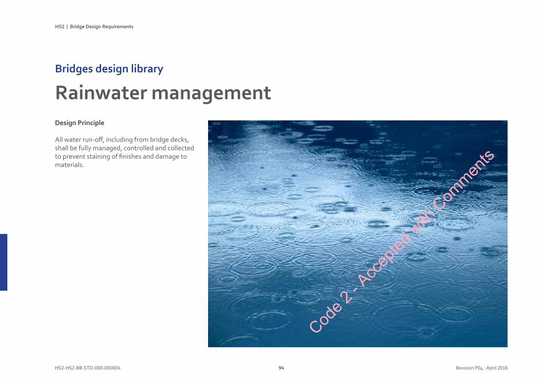
HS2 | Bridge Design Requirements
HS2-HS2-BR-STD-000-000004 94 Revision P04 : April 2016
DesignPrinciple
All water run-off, including from bridge decks, shall be fully managed, controlled and collected to prevent staining of finishes and damage to materials.
RainwatermanagementBridgesdesignlibrary
Code 2
- Acc
epted
with
Com
ments
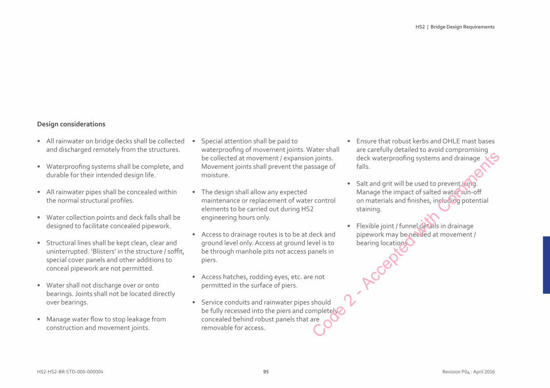
HS2 | Bridge Design Requirements
HS2-HS2-BR-STD-000-000004 95 Revision P04 : April 2016
Designconsiderations
• All rainwater on bridge decks shall be collected and discharged remotely from the structures.
• Waterproofing systems shall be complete, and durable for their intended design life.
• All rainwater pipes shall be concealed within the normal structural profiles.
• Water collection points and deck falls shall be designed to facilitate concealed pipework.
• Structural lines shall be kept clean, clear and uninterrupted. ‘Blisters’ in the structure / soffit, special cover panels and other additions to conceal pipework are not permitted.
• Water shall not discharge over or onto bearings. Joints shall not be located directly over bearings.
• Manage water flow to stop leakage from construction and movement joints.
• Special attention shall be paid to waterproofing of movement joints. Water shall be collected at movement / expansion joints. Movement joints shall prevent the passage of moisture.
• The design shall allow any expected maintenance or replacement of water control elements to be carried out during HS2 engineering hours only.
• Access to drainage routes is to be at deck and ground level only. Access at ground level is to be through manhole pits not access panels in piers.
• Access hatches, rodding eyes, etc. are not permitted in the surface of piers.
• Service conduits and rainwater pipes should be fully recessed into the piers and completely concealed behind robust panels that are removable for access.
• Ensure that robust kerbs and OHLE mast bases are carefully detailed to avoid compromising deck waterproofing systems and drainage falls.
• Salt and grit will be used to prevent icing. Manage the impact of salted water run-off on materials and finishes, including potential staining.
• Flexible joint / funnel details in drainage pipework may be needed at movement / bearing locations.
Code 2
- Acc
epted
with
Com
ments
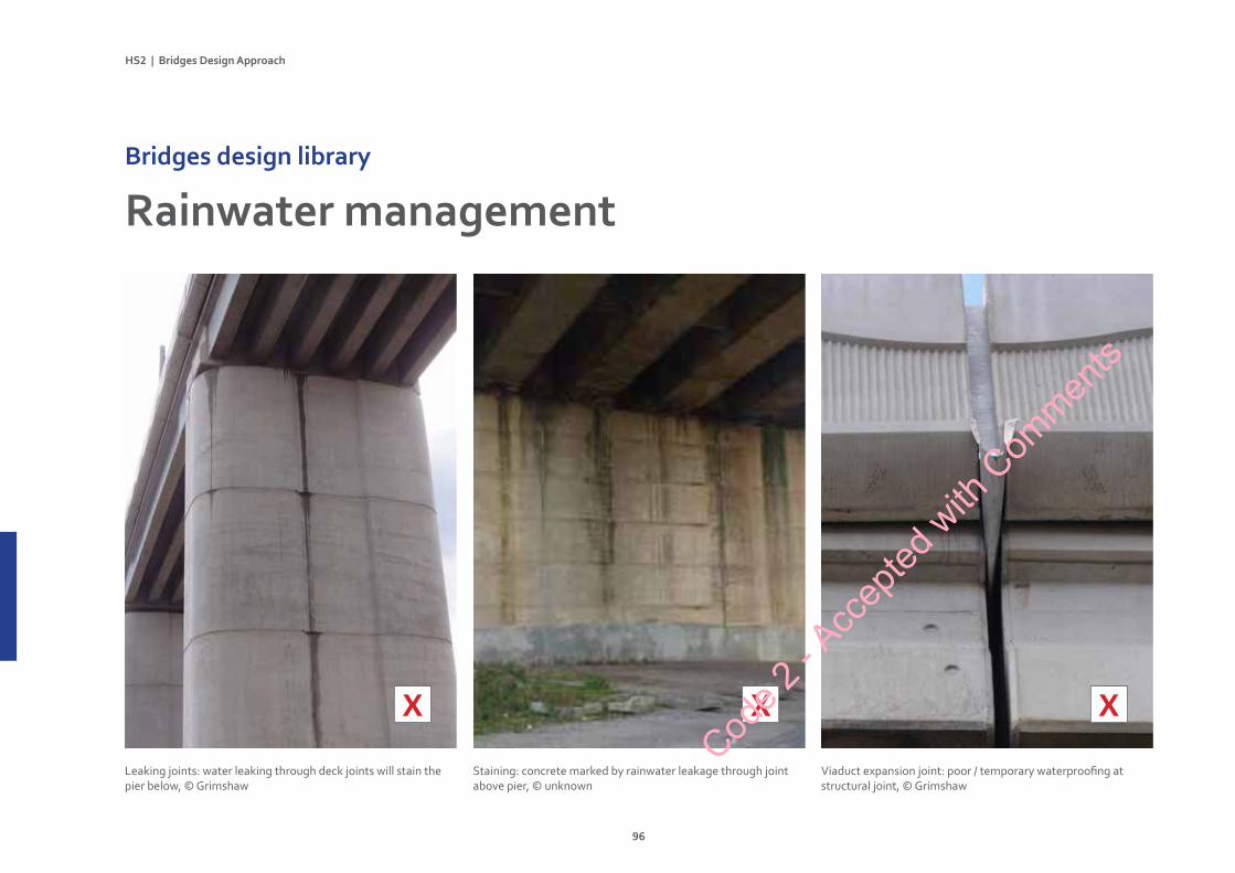
HS2|BridgesDesignApproach
96
RainwatermanagementBridgesdesignlibrary
Staining: concrete marked by rainwater leakage through joint above pier, © unknown
Leaking joints: water leaking through deck joints will stain the pier below, © Grimshaw
Viaduct expansion joint: poor / temporary waterproofing at structural joint, © Grimshaw
XXX
Code 2
- Acc
epted
with
Com
ments
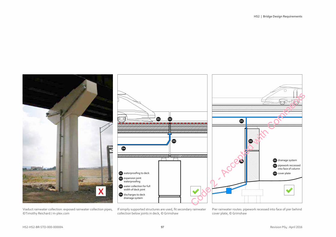
text
HS2 | Bridge Design Requirements
HS2-HS2-BR-STD-000-000004 97 Revision P04 : April 2016
X
If simpily supported structures are used, fit secondary rainwater collection below joints in deck, © Grimshaw
Viaduct rainwater collection: exposed rainwater collection pipes, ©Timothy Reichard / m-plex.com
Pier rainwater routes: pipework recessed into face of pier behind cover plate, © Grimshaw
01
02
03
04
waterproofing to deck
expansion jointwaterproofing
water collection for full width of deck joint
discharges to deck drainage system
01 02
03
04
01
02
03 01
02
03
drainage system
pipework reccessed into face of column
cover plate
Code 2
- Acc
epted
with
Com
ments

HS2 | Bridge Design Requirements
HS2-HS2-BR-STD-000-000004 98 Revision P04 : April 2016
DesignPrinciple
Services and rail systems routing and containment shall not be visible on any structures. Services shall be concealed from any location where there is public access, including where there is public access below bridges.
All services and rail systems shall be fully coordinated with the civil engineering design. A clean, simple, uncluttered appearance is required. No handrails, ladders, pipes, cables, earthing straps, etc. are to be fixed in any locations visible to the public.
ServicesandrailsystemsBridgesdesignlibrary
OHLE setting out: OHLE and structural spans coordinated on Viaduc de la Savoureuse, France, © Réseau Ferré de France
Code 2
- Acc
epted
with
Com
ments
HS2 | Bridge Design Requirements
HS2-HS2-BR-STD-000-000004 99 Revision P04 : April 2016
Designconsiderations
• All service conduits and equipment shall be discreetly positioned and concealed within the normal structural profiles. Exposed conduit and pipes are not acceptable.
• Structural lines shall be kept clean, clear and uninterrupted. ‘Blisters’ in the structure / soffit, special cover panels and other additions to conceal pipework are not permitted.
• Designs shall be fully detailed and coordinated with local authorities, Highways Agency, utility suppliers and other stakeholders to ensure that services can be fully concealed whilst working to third party standards.
• Comprehensive details and interfaces shall be drawn and agreed with third parties to provide adequate control.
• Some overbridges have utility services routes built into the structures. Utility services shall be carefully integrated so that they do not project below the structure and they shall not be placed near or at the edge of the structure.
• Access to service conduits and drainage routes shall be at deck and ground level only. Access at ground level is to be through manhole pits not access panels in piers. Access hatches, rodding eyes, etc. are not permitted in the surface of piers.
• Avoid placement of highway lighting / lamp posts on bridge decks for shorter spans. Consider location carefully and coordinate with views of structure when required on longer decks to manage visual impact. Match existing lighting / lamp post designs where few new units are required.
• Pay special attention to continuity of cross-section for HS2 rail systems routes and containment from adjacent tracks, embankments and cuttings leading up to civil engineering structures. Changes of size or location are vulnerable to construction and maintenance problems. Wherever practicable walkways, OHLE, cableways and drainage should continue at same size and alignment in cuttings, on and below bridges and viaducts.
• OHLE masts, communications masts, etc. should not be mounted on short spanning structures (bridges). Where OHLE masts, communications masts, etc. are required on longer spanning structures (viaducts) their positions should be carefully considered and coordinated to manage visual impact.
• Any lighting for maintenance access on viaducts and under-bridges should default to off and only be switched on when required by staff. Automatic reset switching shall be used to ensure that it stays switched off after overnight use.
• Utilities cabinets and other third party equipment cabinets shall be carefully positioned, ideally off the bridges, and integrated into the surrounding landscape design.
• Cables between piers and bridge decks should ideally connect at fixed bearing points onlyCod
e 2 - A
ccep
ted w
ith C
ommen
ts
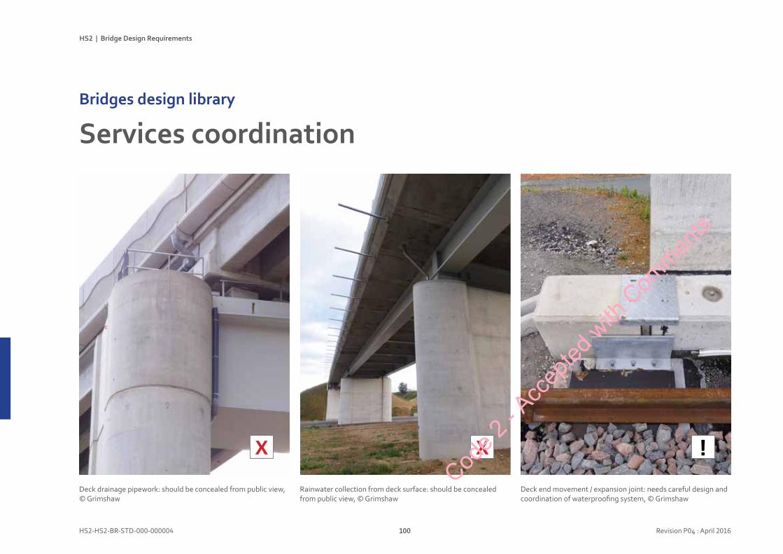
HS2 | Bridge Design Requirements
HS2-HS2-BR-STD-000-000004 100 Revision P04 : April 2016
ServicescoordinationBridgesdesignlibrary
X
Deck drainage pipework: should be concealed from public view, © Grimshaw
Rainwater collection from deck surface: should be concealed from public view, © Grimshaw
X
Deck end movement / expansion joint: needs careful design and coordination of waterproofing system, © Grimshaw
!Cod
e 2 - A
ccep
ted w
ith C
ommen
ts
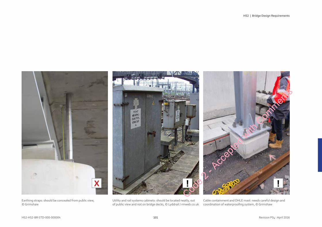
HS2 | Bridge Design Requirements
HS2-HS2-BR-STD-000-000004 101 Revision P04 : April 2016
X
Utility and rail systems cabinets: should be located neatly, out of public view and not on bridge decks, © Lyddrail / rmweb.co.uk
Earthing straps: should be concealed from public view, © Grimshaw
!
Cable containment and OHLE mast: needs careful design and coordination of waterproofing system, © Grimshaw
!Cod
e 2 - A
ccep
ted w
ith C
ommen
ts
HS2 | Bridge Design Requirements
HS2-HS2-BR-STD-000-000004 102 Revision P04 : April 2016
Documentstatus
Code 2
- Acc
epted
with
Com
ments
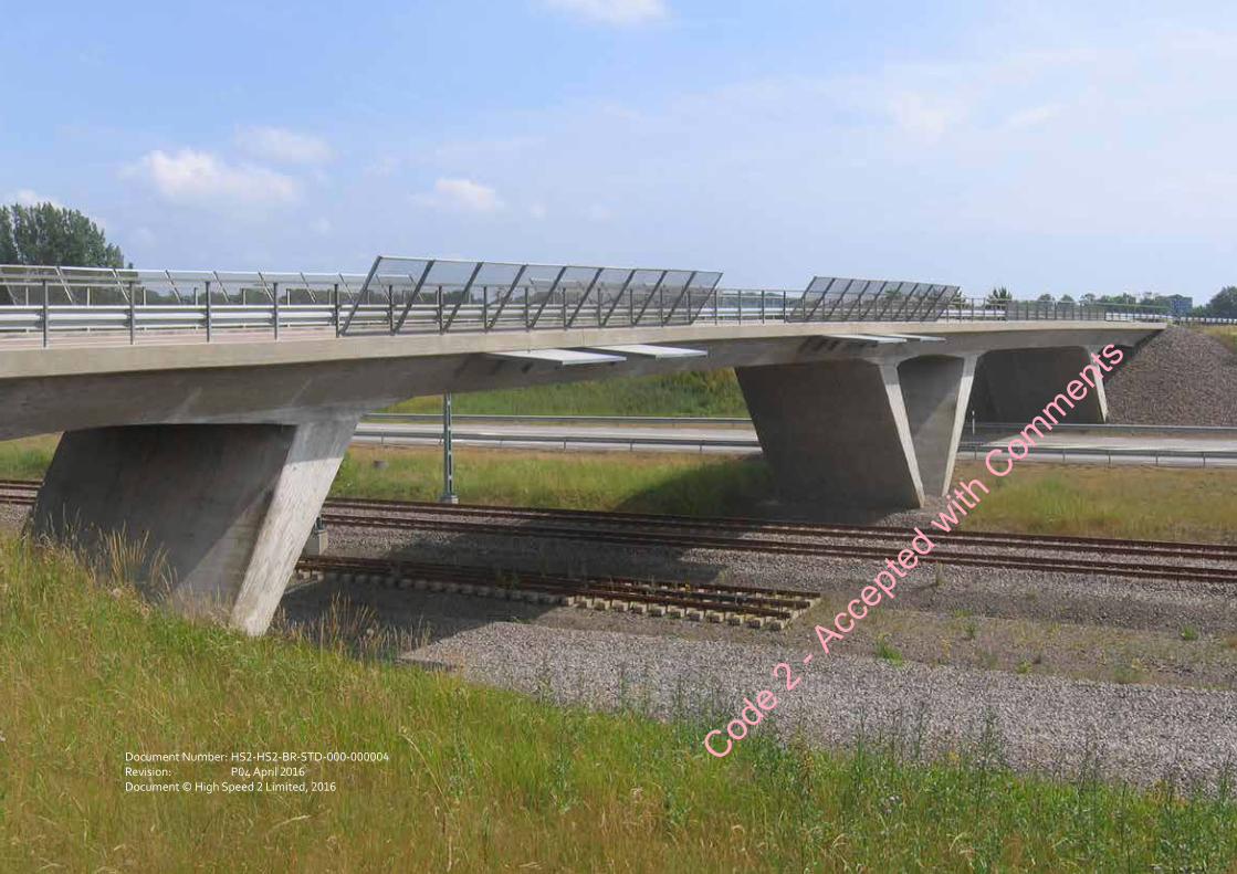
Heading 1
Heading 2Text
HS2 | Bridge Design Requirements
HS2-HS2-BR-STD-000-000004 104 Revision P05 : April 2016
Document Number: HS2-HS2-BR-STD-000-000004Revision: P04 April 2016Document © High Speed 2 Limited, 2016
Code 2
- Acc
epted
with
Com
ments
HS2 | Bridge Design Requirements
103
C227
‐ATK
‐ST‐S
PE‐000
‐000
008 |P01
| 01 May 201
5
<Rep
ort title>
Revision
Da
te
Issued
for/Re
vision
details
Revised by
P01
06/05/2015
Initial issue
Ewan
Jone
s
Nam
e Da
ta
FOI / EIR
Non
e
Documen
t type
Repo
rt
Directorate
Lond
on W
est M
idland
s
MPL & Deliverables R
ef
Keyw
ords
Archite
cture, aesthetics, sp
ecificatio
n
Authors
Ewan
Jone
s
Checker
Oliver M
oen
Approver
Andy
Tye
Owne
r C2
27 Atkins
Review
Dire
ctorate
LWM TD
Employer’s Lead Re
view
er
Tomas Garcia
Authorise
d for u
se
BR
IDG
E A
ESTH
ETIC
DES
IGN
APP
RO
AC
H
C227
‐ATK
‐ST‐SPE‐00
0‐00
0008
|P0
1 | 01
May 201
5
<Rep
ort title>
Revision
Da
te
Issued
for/Re
vision
details
Revised by
P01
06/05/2015
Initial issue
Ewan
Jone
s
Nam
e Da
ta
FOI / EIR
Non
e
Documen
t type
Repo
rt
Directorate
Lond
on W
est M
idland
s
MPL & Deliverables R
ef
Keyw
ords
Archite
cture, aesthetics, sp
ecificatio
n
Authors
Ewan
Jone
s
Checker
Oliver M
oen
Approver
Andy
Tye
Owne
r C2
27 Atkins
Review
Dire
ctorate
LWM TD
Employer’s Lead Re
view
er
Tomas Garcia
Authorise
d for u
se
Oliv
er M
oen
HS2-
HS2-
BR-S
TD-0
00-0
0000
4 |
P05
| 04
Apr
il 20
16
01/0
7/20
15In
itial
issu
eEw
an Jo
nes
P01
Ewan
Jone
s
arch
itect
ure,
aes
theti
cs, s
peci
ficati
on, c
ivil
engi
neer
ing
04/1
2/20
15Re
title
d an
d co
ordi
nate
d w
ith o
ther
doc
s.Ew
an Jo
nes
P02
15/0
3/20
16Te
xt re
vise
d to
cla
rify
man
dato
ry it
ems
Ewan
Jone
sP0
4
08/1
2/20
15Re
vise
d by
HS2
to c
hang
e do
cum
ent ti
tle to
“B
ridge
Des
ign
Requ
irem
ents
” To
mas
Gar
cia,
HS2
P03
04/0
4/20
16Ew
an Jo
nes
P05
For a
ccep
tanc
e
Code 2
- Acc
epted
with
Com
ments
vele9788
Text Box
C227-ATK-ST-SPE-000-000008


![Constructing the Future [HS2]](https://static.fdocuments.us/doc/165x107/55b87f1ebb61ebfb7e8b463d/constructing-the-future-hs2.jpg)