Brickstream 3D Programmer Guide - Video surveillance - Home
37
Programmer's Guide FLIR BRICKSTREAM® 3D Release 5.6 – February 2019 2/21/2019 Names and marks appearing on the products herein are either registered trademarks or trademarks of FLIR Systems, Inc. and/or its subsidiaries. © 2015-2019 FLIR Integrated Imaging Solutions Inc. All rights reserved.
Transcript of Brickstream 3D Programmer Guide - Video surveillance - Home

Programmer's GuideFLIRBRICKSTREAM®
3DRelease 5.6 – February 2019
2/21/2019Names and marks appearing on the products herein are either registeredtrademarks or trademarks of FLIR Systems, Inc. and/or its subsidiaries.© 2015-2019 FLIR Integrated Imaging Solutions Inc. All rights reserved.

Brickstream® 3D Version 5.6
2/21/2019©2015-2019 FLIR IntegratedImaging Solutions Inc.All rights reserved.
Brickstream® 3D Programmer's GuideFebruary 2019
2
FCC Compliance / Conformité FCCThis device complies with Part 15 of the FCC rules. Operation is subject to the following two conditions: (1) Thisdevice may not cause harmful interference, and (2) this device must accept any interference received, includinginterference that may cause undesirable operation.
Cet appareil respecte l’article 15 des règlements du de la Federal Communications Commission (FCC). Sonfonctionnement est soumis aux deux conditions suivantes : (1) cet appareil ne doit pas provoquer d’interférencesnuisibles, et (2) cet appareil doit accepter toutes les interférences reçues, y compris les interférences pouvant engêner le fonctionnement.
Korean EMC Certification / Certification CEM coréenneThe KCC symbol indicates that this product complies with Korea’s Electrical Communication Basic Law regardingEMC testing for electromagnetic interference (EMI) and susceptibility (EMS).
Le symbole KCC indique que ce produit est conforme à la loi-cadre coréenne sur les communications électriques ence qui concerne les essais de compatibilité électromagnétique (CEM) relatifs à la perturbation (EMI) et à lasusceptibilité (EMS) électromagnétiques.
Hardware Warranty / Garantie du matérielThe warranty for the Brickstream sensor is 1 year. For detailed information on how to repair or replace yourcamera, please see the terms and conditions on our website.
La garantie du capteur Brickstream est d’une durée d’un (1) an. Pour connaître la procédure détaillée de réparationou de remplacement de votre caméra, veuillez consulter les conditions sur notre site Web.
WEEEThe symbol indicates that this product may not be treated as household waste. Please ensure thisproduct is properly disposed as inappropriate waste handling of this product may cause potentialhazards to the environment and human health. For more detailed information about recycling of thisproduct, please contact FLIR.
Ce symbole indique que ce produit ne peut être traité comme un déchet ménager. Veuillez vous assurerque ce produit est éliminé de façon adéquate, puisqu’une manipulation inappropriée de celui-ci peutposer un danger pour l’environnement et la santé. Pour en savoir plus sur le recyclage de ce produit,veuillez communiquer avec FLIR.
Caution / AvertissementThis symbol indicates a hot surface. Do not touch. Allow device to cool before handling.
Ce symbole indique la présence d’une surface chaude. Ne pas toucher. Laisser l’appareil refroidiravant de le manipuler.
Use only the recommended PoE injector (FLIR part number ACC-01-9012). Using any other poweradapter or injector may cause damage to the device andmay cause fire or injury.
N’utiliser que l’injecteur PoE recommandé (Numéro de pièce FLIR ACC-01-9012). L’utilisation de toutautre adaptateur ou injecteur risque d’endommager l’appareil et de causer un incendie ou desblessures.
TrademarksNames and marks appearing on the products herein are either registered trademarks or trademarks of FLIRSystems, Inc. and/or its subsidiaries.
LicensingTo view the licenses of open source packages used in this product please see KB11065 What open source packagesdo people counting products use?
Brickstream® 3D Version 5.6
2/21/2019©2015-2019 FLIR IntegratedImaging Solutions Inc.All rights reserved.
Brickstream® 3D Programmer's GuideFebruary 2019
3
ContentsIntroduction 5
About the Brickstream 3D Sensor 5
Hardware Components 5
Software (Firmware) Components 6
System Architecture 7
Exception Conditions 8
Notes on Time Synchronization and Daylight Savings Time 8
Delivery System Features 10
About Encryption 10
XML Metric Data Delivery 10
Real-Time Data Delivery 10
Output Formats 11
FTP Data Delivery 11
Output Format #1 - Pipe Delimited 12
Output Format #2 - XML 13
XML Format 13
Alert Delivery Data Streaming 14
Alert Digital Output 15
Data Buffering 16
Time Synchronization 16
Brickstream 16
Day Time Protocol (RFC 867) 17
SNTP (RFC 4330) 17
Diagnostics 17
Data Flow 20
XML Data Packet Delivery Walkthrough 20
Time Synchronization Walkthrough 21
Sync Request 21
Sync Response 22
Data Management Architecture 22
State 0 24
State 1 (the clock rolls to 10:01:00) 24
State 2 24

Brickstream® 3D Version 5.6
2/21/2019©2015-2019 FLIR IntegratedImaging Solutions Inc.All rights reserved.
Brickstream® 3D Programmer's GuideFebruary 2019
4
State 3 24
HTTP Server 26
Unpacking and Using the Video Capture 28
XML Schemas 29
Locating the XML Schema Files 29
Example Metric File 29
Diagnostic Message Key/Value Pairs 30
Example Diagnostic File 32
Diagnostic Heartbeat Message 35

Brickstream® 3D Version 5.6
2/21/2019©2015-2019 FLIR IntegratedImaging Solutions Inc.All rights reserved.
Brickstream® 3D Programmer's GuideFebruary 2019
5
IntroductionWelcome to the Brickstream 3D sensor. The sensor represents the next generation of video analytics.Brickstream 3D captures and analyzes traffic metrics , queue metrics, service metrics, and full storetrack data in a single sensor for retail outlets, malls, transportation hubs, and smart buildings.
The sensor technical documentation suite includes:
n Brickstream 3D Installation Guide
n Brickstream 3D Counting Configuration Guide
n Brickstream 3D Advanced Configuration Guide
n Brickstream Programmer’s Guide for developers (this document)
Contact your FLIR Brickstream representative for more information.
About the Brickstream 3D SensorThe sensor captures behavior and tracks physical movements that provide a basis for analyticalalgorithms, enabling it to generate traffic metrics, queue metrics, and service metrics in a single sensorfor retail outlets, malls, transportation hubs, and smart buildings.
The sensor:
n Has two camera lenses
n Uses CMOS (complementary metal-oxide semiconductor) image sensors for Wide VGA, HighDynamic Range (HDR) images
n Provides on-board processing and data storage
n Adjusts automatically to environmental changes (i.e., lighting and temperature)
n Is IP addressable for remote management and support, including firmware upgrades
n Offers RS-485 for EAS integration
n Uses proven advanced stereo vision and patented path tracking technology to:
n Collect and store metrics at one minute granularity
n Can distinguish between adults, children, and shopping units and present them as distinctdata metrics
n Filter objects based on height, shape, and size (e.g., children, shopping carts, strollers,etc.)
n Provide robust and accurate metrics across a broad set of environments (e.g.,indoor/outdoor and high traffic)
Hardware Components
The Brickstream sensor is boxed and shipped to a customer. To properly install the sensor, werecommend the purchase of an industry standard 802.3af PoE System. Depending on the method andlocation for installing the sensor, suitable mounting hardware is required (surface mount, recessedmount, RAM mount, or outdoor mount). Mounting hardware is purchased separately.
The following image provides a diagram of the Brickstream sensor.

Brickstream® 3D Version 5.6
2/21/2019©2015-2019 FLIR IntegratedImaging Solutions Inc.All rights reserved.
Brickstream® 3D Programmer's GuideFebruary 2019
6
Software (Firmware) Components
Note: The terms software and firmware are used interchangeablyto refer to programming on the sensor.
The Brickstream sensor is loaded with the available software prior to being shipped to a customer. Itmay be necessary to update the software before installing the sensor. The factory default configurationsare present on the sensor.
The sensor includes a web interface that can be accessed from any standard web browser that canaccess the network where the sensor is connected. The web interface provides configurationcapabilities for the sensor.

Brickstream® 3D Version 5.6
2/21/2019©2015-2019 FLIR IntegratedImaging Solutions Inc.All rights reserved.
Brickstream® 3D Programmer's GuideFebruary 2019
7
Note: The sensor's firmware version is in the footer of the sensorweb interface.
System ArchitectureThe diagram below depicts a common solution architecture for a real-time data feed deployment of the3D. This description ignores all aspects of the network architecture, including network security, andfocuses on the primary components of the architecture.
In the architecture depicted above, the Real-time Data Server is deployed in a centralized Data Center.The Data Server follows a simple client/server model, receiving and processing XML data streams fromany number of 3Ds deployed across any number of stores. These data streams consist of metric data,diagnostic data, and alert data. Many options exists on the server-side implementation, since XML isagnostic to the operating system and other components deployed on the server side.

Brickstream® 3D Version 5.6
2/21/2019©2015-2019 FLIR IntegratedImaging Solutions Inc.All rights reserved.
Brickstream® 3D Programmer's GuideFebruary 2019
8
The 3D sends data at one minute intervals. The 3D does not hold the socket open for data transmission,so that a server side implementation does not need to manage hundreds or thousands of open sockets.
On the server side, the typical implementation is as follows.
1. Open a database connection
2. Listen for a socket connection
3. Fork a new thread
4. Accept a socket connection
5. Read and parse data
6. Write to the database
7. Transmit an acknowledgment on a successful database write
8. Terminate the thread
In the 3D, the following occurs
1. Open a socket
2. Transmit data
3. Read response
4. Update RP on positive acknowledgment
5. If more data to send, go to step 2
6. Close socket
Exception Conditions
Based on the store-and-forward implementation in the 3D, the following exception conditions should behandled by the server side.
n Network failure on acknowledgment response: After the record is written to the database, anetwork failure may be encountered on the transmission of the acknowledgment to the 3D. Theserver may not be aware of the failure, since an application level acknowledgment is notsupported. As a result, it is possible that the 3D forwards the same packet in the next message. Ifthis occurs, the server can discard the retransmitted data packet.
n Device reboot after positive acknowledgment: Since FLASH memory is updated at a frequency ofthree minutes, it is possible that duplicate packets are transmitted for the same three minutewindow as the result of a reboot. In this case, the packets should be discarded.
n Network failure with resumption and reboot: When the network is down, data is buffered fortransmission. When network communications are restored, data is now forwarded to the serveras quickly as possible. If a reboot occurs during this data forwarding, it results in theretransmission of some number of duplicate data packets. These packets should be discarded onthe server side.
Notes on Time Synchronization and Daylight Savings Time
One additional note is the handling of changes in time resulting from time synchronization or daylightsavings time. Small shifts in time have no impact on the data transmission. The primary area ofconcern is a time shift to an earlier time interval. If this occurs, metric data is stored in the current timebucket prior to the time shift. For example, the current time is 10:05:35 and data for the 10:04:00 bucket

Brickstream® 3D Version 5.6
2/21/2019©2015-2019 FLIR IntegratedImaging Solutions Inc.All rights reserved.
Brickstream® 3D Programmer's GuideFebruary 2019
9
has been transmitted and successfully stored in the database. If a time synchronization event occursand the clock shifts to 10:04:30, the 3D adds the additional counts occurring between 10:04:30 and10:05:00 to the 10:05:00 bucket. The 3D does not retransmit the 10:04:00 time bucket. If a time shift isgreater than 5 minutes and results in a day shift to a previous day, the current day and any future daysare reset.
Daylight savings time is handled using the same mechanism. If time jumps forward, 60 one-minutebuckets are transmitted with 0 counts for the missing time period. If time jumps backwards, the countsfor the next 60 minutes after the time shift are aggregated in the first minute of the next hour. Forexample, at 2:00:00 am time shifts back. Data for the next 60 minutes is collected in the 2:00:00 am timebucket and transmitted in one message.

Brickstream® 3D Version 5.6
2/21/2019©2015-2019 FLIR IntegratedImaging Solutions Inc.All rights reserved.
Brickstream® 3D Programmer's GuideFebruary 2019
10
Delivery System FeaturesThis section describes the basic features of the delivery system. The 3D can send data out via an XMLstream that is sent out at a set interval, a real-time data stream, e-mail, or scheduled FTP file transfers inXML or pipe delimited format.
About EncryptionThe 3D supports SSL encryption. The Brickstream Device Adapter startup command uses thebrickstream.ks file and a keystore password parameter passed in through the service startup commandto set the encryption key. The encryption key can be changed by opening the<installdir>\resources\ServicesInfo.properties file and changing the -Djavax.net.ssl.keyStorePassword=123456 parameter to the key of your choice.
XML Metric Data DeliveryOnce configured and installed, the 3D sends XML data packets containing metric data to the configureddelivery address and port at the select time interval (1, 5, 15, 30, or 60 minutes). The data deliveryaddress and port are set from the Web Interface (see 3D Installation and Configuration Guide).
Each data packet is tagged with a status number (0-4). This status number can tell you various thingsabout the status of the 3D at the time the packet was created:
0 = The 3D was online and collecting data during this particular time interval. The data you are receivingis actual count data received by the sensor.
1 = The 3D was offline during this particular time interval. The data you are receiving is beingautomatically generated as zeros by the sensor.
2 or 3 = The zone didn’t exist during the time interval being sent but has since been created. Thissituation can occur when a new zone is created on a 3D that currently has data cached and ready tosend to the server. Once the cached data is sent to the server, all data packets should return to zerostatus.
4 = The Tracking Engine was disabled due to quality constraints during this particular time interval andwas unable to accurately count.
Real-Time Data DeliveryThe 3D also has the ability to send a real-time data stream at a set time interval. This is configured fromthe Basic Settings tab -> Data Delivery sub-tab -> Real-time Data Streaming section. Once enabled, the3D sends an XML stream to the configured IP address and port at the configured time interval. The real-time data stream does not require an Acknowledgment from any service if the protocol is set to TCP orVLI , it simply sends the metrics out at the desired interval. If the protocol is set to HTTP POST or HTTP,an Acknowledgment (ACK) is required from the receiving service.
Brickstream® 3D Version 5.6
2/21/2019©2015-2019 FLIR IntegratedImaging Solutions Inc.All rights reserved.
Brickstream® 3D Programmer's GuideFebruary 2019
11
Note: If an HTTP POST or HTTP transmission fails, the failedpacket count is incremented and the connection is closed, themessage is not resent.
Output Formats
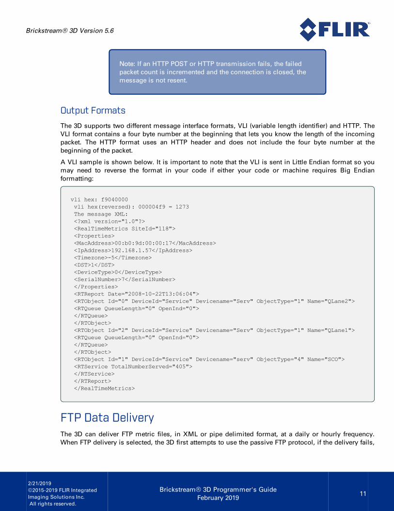
The 3D supports two different message interface formats, VLI (variable length identifier) and HTTP. TheVLI format contains a four byte number at the beginning that lets you know the length of the incomingpacket. The HTTP format uses an HTTP header and does not include the four byte number at thebeginning of the packet.
A VLI sample is shown below. It is important to note that the VLI is sent in Little Endian format so youmay need to reverse the format in your code if either your code or machine requires Big Endianformatting:
vli hex: f9040000vli hex(reversed): 000004f9 = 1273The message XML:<?xml version="1.0"?><RealTimeMetrics SiteId="118"><Properties><MacAddress>00:b0:9d:00:00:17</MacAddress><IpAddress>192.168.1.57</IpAddress><Timezone>-5</Timezone><DST>1</DST><DeviceType>0</DeviceType><SerialNumber>7</SerialNumber></Properties><RTReport Date="2008-10-22T13:06:04"><RTObject Id="0" DeviceId="Service" Devicename="Serv" ObjectType="1" Name="QLane2"><RTQueue QueueLength="0" OpenInd="0"></RTQueue></RTObject><RTObject Id="2" DeviceId="Service" Devicename="Serv" ObjectType="1" Name="QLane1"><RTQueue QueueLength="0" OpenInd="0"></RTQueue></RTObject><RTObject Id="1" DeviceId="Service" Devicename="serv" ObjectType="4" Name="SCO"><RTService TotalNumberServed="405"></RTService></RTReport></RealTimeMetrics>
FTP Data DeliveryThe 3D can deliver FTP metric files, in XML or pipe delimited format, at a daily or hourly frequency.When FTP delivery is selected, the 3D first attempts to use the passive FTP protocol, if the delivery fails,

Brickstream® 3D Version 5.6
2/21/2019©2015-2019 FLIR IntegratedImaging Solutions Inc.All rights reserved.
Brickstream® 3D Programmer's GuideFebruary 2019
12
the device attempts to use active FTP. The use of passive FTP requires that you open the high number(>1024) ports on the server machine.
Note: When using active FTP, the connection attempts to use theIP address of the Brickstream sensor and the full port range toestablish a connection unless other options have been selectedin the Active FTP section in the FTP Delivery options.
The FTP delivery options are configured from the Basic Settings tab -> Data Delivery section. Refer tothe 3D Installation and Configuration Guide for instructions on configuring Data Delivery.
Output Format #1 - Pipe Delimited
The Pipe Delimited format sends data for each report zone with the relevant information separated by apipe character “|”.
For example:25|789|234|9999|Exit & Entrance|2|12/21/2006 09:40:00|7|5|13|11|10.38.9.130|
The fields in the pipe delimited file are as follows:
Field Description
Event Type Contains the type of event that is being transmitted. This value is always “25”.
Division IDContains the value from the Division ID field on the Basic Settings->IP Settings page.Supports a maximum of 31 characters. The maximum allowed length is 31 bytes.
Store IDContains the value from the Site ID field on the Basic Settings->IP Settings page.Supports a maximum of 31 characters. The maximum allowed length is 31 bytes.
Door IDContains the zone External ID from the Counting tab. Supports a maximum of 31characters. The maximum allowed length is 31 bytes.
DoorDescription
Contains the zone Name from the Counting tab. The maximum allowed length is 31bytes.
Door Type Contains the door type. This value is always “2”.
Local Dateand Time
Contains the local site date and time of the data packet.
In CountContains the count of customer enters over the time interval set in the Aggregation Leveldrop-down.
Out CountContains the count of customer exits over the time interval set in the Aggregation Leveldrop-down.
CumulativeEnter Count
Contains the count of customer enters for the zone since the zone was created or sincethe last counter reset.
CumulativeExit Count
Contains the count of customer exits for the zone since the zone was created or since thelast counter reset.

Brickstream® 3D Version 5.6
2/21/2019©2015-2019 FLIR IntegratedImaging Solutions Inc.All rights reserved.
Brickstream® 3D Programmer's GuideFebruary 2019
13
Field Description
3D IPAddress
Contains the IP address of the 3D unit.
Output Format #2 - XML
XML FormatThe XML format sends metric data in an XML file similar to the XML packets that are sent out using theBatch Data Streaming option. The XML below is a sample hourly XML file sent by a 3D with two zones.
<?xml version="1.0"?><Metrics SiteId="461" Sitename="Site C"><Properties><MacAddress>00:b0:9d:70:01:05</MacAddress><IpAddress>192.168.1.56</IpAddress><Timezone>-5</Timezone><DST>1</DST><DeviceType>0</DeviceType><SerialNumber>7340293</SerialNumber></Properties><ReportData Interval="5"><Report Date="2015-02-26"><Object Id="0" DeviceId="Cam003" Devicename="DoorCam1" ObjectType="0" Name="Door1"><Count StartTime="16:00:00" EndTime="16:05:00" UnixStartTime="1424966400" Enters="0"Exits="0" Status="0"/><Count StartTime="16:05:00" EndTime="16:10:00" UnixStartTime="1424966700" Enters="0"Exits="0" Status="0"/><Count StartTime="16:10:00" EndTime="16:15:00" UnixStartTime="1424967000" Enters="0"Exits="0" Status="0"/><Count StartTime="16:15:00" EndTime="16:20:00" UnixStartTime="1424967300" Enters="0"Exits="0" Status="0"/><Count StartTime="16:20:00" EndTime="16:25:00" UnixStartTime="1424967600" Enters="0"Exits="0" Status="0"/><Count StartTime="16:25:00" EndTime="16:30:00" UnixStartTime="1424967900" Enters="0"Exits="0" Status="0"/><Count StartTime="16:30:00" EndTime="16:35:00" UnixStartTime="1424968200" Enters="0"Exits="0" Status="0"/><Count StartTime="16:35:00" EndTime="16:40:00" UnixStartTime="1424968500" Enters="0"Exits="0" Status="0"/><Count StartTime="16:40:00" EndTime="16:45:00" UnixStartTime="1424968800" Enters="0"Exits="0" Status="0"/><Count StartTime="16:45:00" EndTime="16:50:00" UnixStartTime="1424969100" Enters="0"Exits="0" Status="0"/><Count StartTime="16:50:00" EndTime="16:55:00" UnixStartTime="1424969400" Enters="0"Exits="0" Status="0"/><Count StartTime="16:55:00" EndTime="17:00:00" UnixStartTime="1424969700" Enters="0"Exits="0" Status="0"/></Object><Object Id="1" DeviceId="Cam003" Devicename="DoorCam1" ObjectType="0" Name="Door2"><Count StartTime="16:00:00" EndTime="16:05:00" UnixStartTime="1424966400" Enters="0"Exits="0" Status="0"/><Count StartTime="16:05:00" EndTime="16:10:00" UnixStartTime="1424966700" Enters="0"

Brickstream® 3D Version 5.6
2/21/2019©2015-2019 FLIR IntegratedImaging Solutions Inc.All rights reserved.
Brickstream® 3D Programmer's GuideFebruary 2019
14
Exits="0" Status="0"/><Count StartTime="16:10:00" EndTime="16:15:00" UnixStartTime="1424967000" Enters="0"Exits="0" Status="0"/><Count StartTime="16:15:00" EndTime="16:20:00" UnixStartTime="1424967300" Enters="0"Exits="0" Status="0"/><Count StartTime="16:20:00" EndTime="16:25:00" UnixStartTime="1424967600" Enters="0"Exits="0" Status="0"/><Count StartTime="16:25:00" EndTime="16:30:00" UnixStartTime="1424967900" Enters="0"Exits="0" Status="0"/><Count StartTime="16:30:00" EndTime="16:35:00" UnixStartTime="1424968200" Enters="0"Exits="0" Status="0"/><Count StartTime="16:35:00" EndTime="16:40:00" UnixStartTime="1424968500" Enters="0"Exits="0" Status="0"/><Count StartTime="16:40:00" EndTime="16:45:00" UnixStartTime="1424968800" Enters="0"Exits="0" Status="0"/><Count StartTime="16:45:00" EndTime="16:50:00" UnixStartTime="1424969100" Enters="0"Exits="0" Status="0"/><Count StartTime="16:50:00" EndTime="16:55:00" UnixStartTime="1424969400" Enters="0"Exits="0" Status="0"/><Count StartTime="16:55:00" EndTime="17:00:00" UnixStartTime="1424969700" Enters="0"Exits="0" Status="0"/></Object></Report></ReportData></Metrics>
Alert Delivery Data StreamingThe Alert Delivery Data Streaming options are typically used for two purposes:
n To provide support for OEM partners seeking to integrate 3D devices with existing legacycounting systems that use a pulse system to aggregate counts from devices.
n To allow integrators to setup tripwire logic in which the 3D sends an alert when the count linesare crossed. This can be used to indicate intrusions and behavioral alerts.
The OEM User Guide describes how to configure the 3D to send the alerts. The alerts can be deliveredvia HTTP, HTTP POST, TCP, or VLI protocols.
The VLI (variable length identifier) format contains a four byte number at the beginning that lets youknow the length of the incoming packet. It is important to note that the VLI is sent in Little Endianformat so you may need to reverse the format in your code if either your code or machine requires BigEndian formatting.
Note: When creating adapters to receive Alert Delivery Datastreams, you should note that delivery in VLI and TCP formatsdo not require and acknowledgment (ACK) from the adapter.When the delivery format is set to HTTP POST or HTTP GET, anACK is required from the receiving software interface.
Brickstream® 3D Version 5.6
2/21/2019©2015-2019 FLIR IntegratedImaging Solutions Inc.All rights reserved.
Brickstream® 3D Programmer's GuideFebruary 2019
15
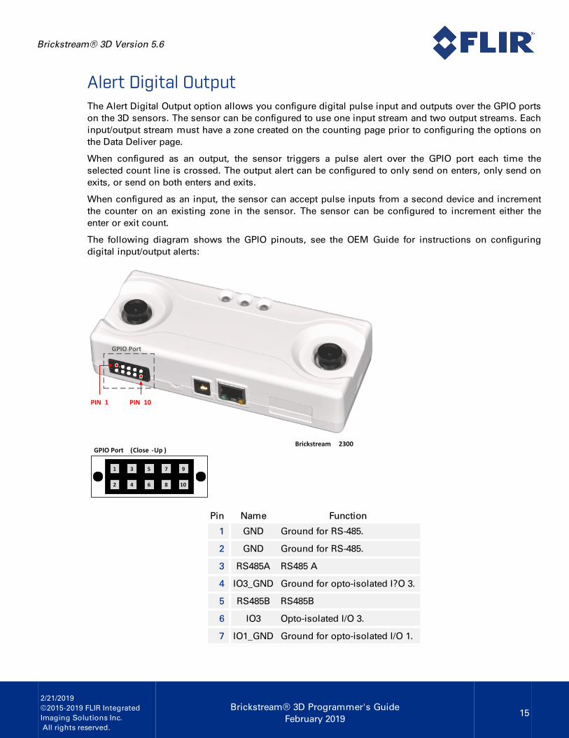
Alert Digital OutputThe Alert Digital Output option allows you configure digital pulse input and outputs over the GPIO portson the 3D sensors. The sensor can be configured to use one input stream and two output streams. Eachinput/output stream must have a zone created on the counting page prior to configuring the options onthe Data Deliver page.
When configured as an output, the sensor triggers a pulse alert over the GPIO port each time theselected count line is crossed. The output alert can be configured to only send on enters, only send onexits, or send on both enters and exits.
When configured as an input, the sensor can accept pulse inputs from a second device and incrementthe counter on an existing zone in the sensor. The sensor can be configured to increment either theenter or exit count.
The following diagram shows the GPIO pinouts, see the OEM Guide for instructions on configuringdigital input/output alerts:
1 3 5 7 9
2 4 6 8 10
GPIO Port (Close -Up )Brickstream 2300
PIN 10PIN 1
GPIO Port
Pin Name Function
1 GND Ground for RS-485.
2 GND Ground for RS-485.
3 RS485A RS485 A
4 IO3_GND Ground for opto-isolated I?O 3.
5 RS485B RS485B
6 IO3 Opto-isolated I/O 3.
7 IO1_GND Ground for opto-isolated I/O 1.

Brickstream® 3D Version 5.6
2/21/2019©2015-2019 FLIR IntegratedImaging Solutions Inc.All rights reserved.
Brickstream® 3D Programmer's GuideFebruary 2019
16
Pin Name Function
8 IO2_GND Ground for opto-isolated I/O 2.
9 IO1 Opto-isolated I/O 1.
10 IO2 Opto-isolated I/O 2.
Data BufferingThe 3D is also programmed to buffer the data for up to 200 days should a network or power outageoccur that prohibits the device from successfully delivering to the server. Data is stored in RAM at a oneminute granularity. Every three minutes the data is stored in nonvolatile FLASH memory. Once thedevice is able to establish a connection to the server, buffered data packets are sent to the server. SeeData Management Architecture for more details.
Note: The sensor does not buffer data for the real-time datastream.
Time SynchronizationThe 3D conducts time synchronization callouts to the configured time synchronization server every 15minutes. Once a connection is made, the server responds to the device and set the clock to GMT time.
Note: To find the current GMT time, direct your browser tohttp://wwp.g-m-t.com/gmt.htm.
3D devices support three types of time synchronization protocols:
n Brickstream
n Day Time (RFC 867)
n SNTP (RFC 4330)
Brickstream
The Brickstream format sets the 3D to use a time synchronization server developed by FLIR tosynchronize the 3D. This method uses HTTP headers to notify the server that a time synchronization isbeing attempted. By default, this server runs on port 2000 but can be configured to use other ports.

Brickstream® 3D Version 5.6
2/21/2019©2015-2019 FLIR IntegratedImaging Solutions Inc.All rights reserved.
Brickstream® 3D Programmer's GuideFebruary 2019
17
Note: To use the Brickstream proprietary time sync protocol youmust use Device Manager to provide the time sync. The timesynchronization port and data delivery port can be sent to thesame IP address and port if necessary, except when opting foreither daytime or SNTP protocol.
Day Time Protocol (RFC 867)
A server listens for TCP connections on TCP port 13. Once a connection is established, the current dateand time are sent out as an ASCII character string. The service closes the connection after sending thedate and time.
SNTP (RFC 4330)
An SNTP server listens on UDP port 123. Once a connection is established, the current date and timeare sent out. The service closes the connection after sending the date and time.
DiagnosticsThe sensor sends a diagnostic heartbeat every 15 minutes. See the diagnostic schema in XML Schemasfor the contents of the heartbeat message. In addition to the 15 minute heartbeat, the device also sendsalerts on the occurrence or detection of the following events:
Level IDEventID
Alert Message Message/Corrective Action
Info (2) 1Successfully sentCount Emails
The sensor successfully connected to the mail server andsent the daily count data.
Error (4) 2 <text>The sensor failed while attempting to send the daily countemail. The text of the log message from the mail server isdisplayed.
Error (4) 3
Error writingconfigurationparameters to flash.Error <text>
A hardware issue prevented the write to flash memory.Reboot the device, retry the command and contactBrickstream if the problem persists.
Info (2) 9
Configurationparameterssuccessfully writtento flash
A save command was successfully completed from thesensor configuration application.
Error (4) 10Unable to findtimezone delimiterfor timezone: <text>
An invalid time zone setting was received. ContactBrickstream.

Brickstream® 3D Version 5.6
2/21/2019©2015-2019 FLIR IntegratedImaging Solutions Inc.All rights reserved.
Brickstream® 3D Programmer's GuideFebruary 2019
18
Level IDEventID
Alert Message Message/Corrective Action
Error (4) 10Unable to findtimezone with key:<text>
Contact Brickstream.
Error (4) 20 <info>Error writing to SD. Card has prevented AVI capture. Retrythe operation. If the error continues, contact Brickstream.
Error (4) 21 <info>Error writing to SD. Card has prevented AVI capture. Retrythe operation. If the error continues, contact Brickstream.
Error (4) 22 <info>Error storing AVI capture data to SD because the SD card isout of space. Transmit existing files on SD to the ftp serveror capture for a shorter time.
Info (2) 12See diagnosticschema for heartbeat
Diagnostic message.
Error (4) 3Unable to obtainflash write lock
There was a memory write error. Reboot the sensor, retrythe command. Contact Brickstream if the problem persists.
Error (4) 3
Error reading orwriting to Flash.Error <text><function> <text>
There was a memory write error. Reboot the sensor, retrythe command. Contact Brickstream if the problem persists.
Fatal (5) 8
Unable to allocatememory: buffer size= <text> bytes.Hostname: <text>Filename: <text>
There was a memory write error, contact Brickstream.
Info (2) 8 <text>Informational message that contains memory details withrespect to the FLASH memory.
Fatal (5) 8Tftp upload error.Tftp return code:<text>
There was an error while uploading a new firmwareapplication. This problem is most likely network related,retry the software upload.
Info (2) 11
Timestamp shift.Current DateTimevalue: <text>. LastTimestamp recorded<text>
There was a shift in the time on the sensor clock. Comparethe current value to the last recorded value, if the differenceis greater and 20 seconds report it to Brickstream.
Info (2) 7
Successfullyupgraded the 3Dfirmware at <text>with <text>
A sensor upgrade was successfully performed.
Error (4) 3Unable to upgradethe 3D firmware at<text> with <text>
An upgrade failure has occurred. Contact Brickstream.

Brickstream® 3D Version 5.6
2/21/2019©2015-2019 FLIR IntegratedImaging Solutions Inc.All rights reserved.
Brickstream® 3D Programmer's GuideFebruary 2019
19
Level IDEventID
Alert Message Message/Corrective Action
Info (2) 6System rebooted:<text>
The system was rebooted due to a reboot command beingissued or a power loss.
Debug 13 <info>This is a memory dump of calibration data triggered by acalibration operation.
Fatal (5) 4 <info>
The environment at the site is too dark for accurate trackingso the 3D has shut down the tracking system. This usuallyoccurs during store closed hours when interior lights areturned off. If the problem persists or occurs during openhours, contact Brickstream.
Info (2) 5 <info>The lighting at the site has increased and tracking hasresumed.
Error (4) 14 <info>Error on time synchronization due to invalid packet format,network timeout, or some other error on the time syncserver side.
Fatal (5) 15 <info>
The stereo data from the 3D is too noisy for the system toproperly track. If the system is properly tracking, anadjustment in parameters found on the Tracking pageQuality tab my need adjustments. This typically occursduring darkness and may be associated with alert #4. If thisoccurs during normal lighting conditions, contactBrickstream since this may be the result of a calibrationissue.
Fatal (5) 16 <info>
The 3D is not able to generate 3D stereo readings for a largeportion of the image. If the system is tracking properly, anadjustment in parameters found on the Tracking page,Quality tab may need adjustments. This typically occursduring darkness and may be associated with alert #4. If thisoccurs during normal lighting conditions, contactBrickstream since this may be the result of a calibrationissue.
Fatal (5) 17 <info>
Out of memory. This occurs when the scene has becometoo crowded for the 3D to properly track. This typically onlyoccurs when 30 or more people are in the field-of-view of the3D. When 3Ds are mounted within the height specification,it is unlikely the event will occur. See the 3D OEM UserGuide for height specifications. If this error is encountered,contact Brickstream.

Brickstream® 3D Version 5.6
2/21/2019©2015-2019 FLIR IntegratedImaging Solutions Inc.All rights reserved.
Brickstream® 3D Programmer's GuideFebruary 2019
20
Data FlowThe sensor sends an HTTP POST whose content is the XML metric file and waits for anAcknowledgment or Negative Acknowledgment response from the server. If the sensor has more datapackets in the buffer, the device issues an HTTP POST for the each of the other packets in sequenceduring the same connection until all data packets have been successfully delivered. After all packetshave been sent and acknowledged, the sensor closes the connection.
XML Data Packet Delivery WalkthroughThe data packet is sent from the sensor in the form of an HTTP POST to the IP address configured in theconfiguration application. The target specified in the HTTP header is POST / HTTP/1.1. The contentlength in the HTTP header describes the length of the XML message. In the example below, the headeris in red, and the XML message is in blue.
POST / HTTP/1.1Accept: image/gif, image/x-xbitmap, image/jpeg, image/pjpeg, application/vnd.ms-excel,application/msword, application/x-shockwave-flash, text/*,*/*Accept-Language: en-usContent-Type: application/x-www.form-urlencodedAccept-Encoding: gzip, deflateUser-Agent: Mozilla/4.0 (compatible; MSIE 6.0,; Windows NT 5.1; .NET CLR 1.0.3705)Content-Length: 262Connection: Keep-Alive<CRLF><--end of header<?xml version="1.0"?><Metrics SiteId="AlexSite" Sitename="AlexSite" DeviceId="Lab-96" Devicename="QA Lab96" DivisionId="123"><Properties><Version>2</Version><TransmitTime>1493132892</TransmitTime><MacAddress>00:b0:9d:b9:bb:ec</MacAddress><IpAddress>10.5.1.96</IpAddress><HostName>Cam-12172268</HostName><HttpPort>80</HttpPort><HttpsPort>443</HttpsPort><Timezone>-5</Timezone><TimezoneName>(GMT-05:00) Eastern Time (US Canada)</TimezoneName><DST>1</DST><HwPlatform>2300</HwPlatform><SerialNumber>12172268</SerialNumber><DeviceType>0</DeviceType><SwRelease>5.2.123.467</SwRelease></Properties><ReportData Interval="1"><Report Date="2017-04-25"><Object Id="0" DeviceId="Lab-96" Devicename="QA Lab 96" ObjectType="0" Name="Count"><Count StartTime="10:45:00" EndTime="10:46:00" UnixStartTime="1493131500" Enters="0"
Brickstream® 3D Version 5.6
2/21/2019©2015-2019 FLIR IntegratedImaging Solutions Inc.All rights reserved.
Brickstream® 3D Programmer's GuideFebruary 2019
21
Exits="0" Status="0"/></Object></Report></ReportData></Metrics>
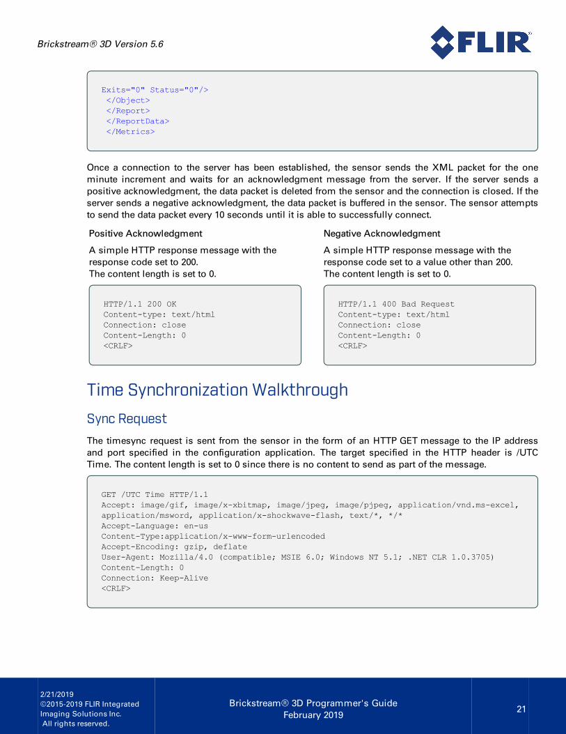
Once a connection to the server has been established, the sensor sends the XML packet for the oneminute increment and waits for an acknowledgment message from the server. If the server sends apositive acknowledgment, the data packet is deleted from the sensor and the connection is closed. If theserver sends a negative acknowledgment, the data packet is buffered in the sensor. The sensor attemptsto send the data packet every 10 seconds until it is able to successfully connect.
Positive Acknowledgment
A simple HTTP response message with theresponse code set to 200.The content length is set to 0.
HTTP/1.1 200 OKContent-type: text/htmlConnection: closeContent-Length: 0<CRLF>
Negative Acknowledgment
A simple HTTP response message with theresponse code set to a value other than 200.The content length is set to 0.
HTTP/1.1 400 Bad RequestContent-type: text/htmlConnection: closeContent-Length: 0<CRLF>
Time Synchronization Walkthrough
Sync Request
The timesync request is sent from the sensor in the form of an HTTP GET message to the IP addressand port specified in the configuration application. The target specified in the HTTP header is /UTCTime. The content length is set to 0 since there is no content to send as part of the message.
GET /UTC Time HTTP/1.1Accept: image/gif, image/x-xbitmap, image/jpeg, image/pjpeg, application/vnd.ms-excel,application/msword, application/x-shockwave-flash, text/*, */*Accept-Language: en-usContent-Type:application/x-www-form-urlencodedAccept-Encoding: gzip, deflateUser-Agent: Mozilla/4.0 (compatible; MSIE 6.0; Windows NT 5.1; .NET CLR 1.0.3705)Content-Length: 0Connection: Keep-Alive<CRLF>

Brickstream® 3D Version 5.6
2/21/2019©2015-2019 FLIR IntegratedImaging Solutions Inc.All rights reserved.
Brickstream® 3D Programmer's GuideFebruary 2019
22
Sync Response
The server responds to the timesync request with an HTTP response setting the response code to 200,and the content length of 14 (MMddyyyyHHmmss). The time value is specified in the content field inblue.
HTTP/1.1 200 OKContent-type: text/htmlConnection: closeContent-Length: 14<CRLF>07172017220705
MM Month
dd Day
yyyy Year
HH Hours (24-hour clock)
mm Minutes
ss Seconds
Date Format
In the example above 07172017220705 translates to: July 17, 2017 at 10:07:05 pm.
Data Management ArchitectureThe 3D implements a store-and-forward architecture for data management which provides streamingdata delivery and long-term persistent data storage. If a 3D can connect to a data server, it forwards itsmetric data at the selected time interval over a socket connection. If a 3D loses network connectivity orcan not connect to a data server it stores the metric data for up to 200 days. During this time the 3Dcontinues to attempt to open a connection with the designated server.
The 3D accomplishes the store-and-forward architecture through the use of a logical table and twopointers. The table contains data for up to ten days and six reporting objects. Examples of a reportingobjects are "entrances", "exits", "queues", "Service", "detection", etc. Each queue, service, and detectionobject stores data relevant to the specific type of report object.
The table for count data contains the following data elements
n Date
n Time
n Object Identifier
n Enter Count
n Exit Count
n Status
Each row in the table contains information for a one minute time period. The following is an examplesnapshot of the internal table.

Brickstream® 3D Version 5.6
2/21/2019©2015-2019 FLIR IntegratedImaging Solutions Inc.All rights reserved.
Brickstream® 3D Programmer's GuideFebruary 2019
23
Date Time ID Enter Exit Status
...
4/15/2007 10:00:00 0 4 2 0
4/15/2007 10:01:00 0 3 4 0
4/15/2007 10:02:00 0 0 1 0
4/15/2007 10:03:00 0 1 3 0
4/15/2007 10:04:00 0 2 4 0
4/15/2007 10:05:00 0 5 2 0
4/15/2007 10:06:00 0 3 4 0
...
Since the table is a finite size, it is managed as a circular buffer. Two pointers are maintained for buffermanagement, a read pointer (RP) and a write pointer (WP). WP points to the time bucket that data isbeing stored for the current moment in time. RP points to the next time bucket of data to be transmittedto a server. Note, RP is only used for configurations which are configured for real-time data delivery.
Pointer Date Time ID
...
4/15/2007 10:00:00 ...
4/15/2007 10:01:00 ...
RP, WP -> 4/15/2007 10:02:00 ...
4/15/2007 ... ...
The example above shows the table under normal operation, i.e. the network is up and data is beingsuccessfully delivered to a server. The 3D is collecting data for the bucket 4/15/2005 10:02:00. When theclock in the 3D rolls over to 10:04:00, the WP pointer is updated to the next time bucket.
Pointer Date Time ID
...
4/15/2007 10:00:00 ...
4/15/2007 10:01:00 ...
RP -> 4/15/2007 10:02:00 ...
WP -> 4/15/2007 10:03:00 ...
Since the RP pointer is now pointing to a complete time bucket, this data can be delivered to real-timedata server. The XML data packet is prepared and transmitted to the server over http protocol. The 3Dlistens for a response. If a positive acknowledgment is received, the RP is updated to the next timebucket.

Brickstream® 3D Version 5.6
2/21/2019©2015-2019 FLIR IntegratedImaging Solutions Inc.All rights reserved.
Brickstream® 3D Programmer's GuideFebruary 2019
24
Pointer Date Time ID
...
4/15/2007 10:00:00 ...
4/15/2007 10:01:00 ...
4/15/2007 10:02:00 ...
RP, WP -> 4/15/2007 10:03:00 ...
If a response is not received or a negative acknowledgment is received, the RP pointer is not updated.The 3D retries the transmission in 10 seconds. In the event of a network failure or a failure in the real-time data server, the WP continues to increment and move forward.
Pointer Date Time ID
...
4/15/2007 10:00:00 ...
4/15/2007 10:01:00 ...
RP -> 4/15/2007 10:02:00 ...
...
WP -> 4/16/2007 3:03:00 ...
In the example above, the network failed at 4/15/2007 10:02:00. The 3D continues to count and store data.When the network failure is corrected, data is then forwarded to the real-time data server one packet at atime. The RP pointer is only updated when an acknowledgment is received.
Under normal operations, the following occurs.
State 0
RP,WP -> 4/15/2007 10:00:00
State 1 (the clock rolls to 10:01:00)
RP -> 4/15/2007 10:00:00
WP -> 4/15/2007 10:01:00
State 2
3D transmits packet to server -----------'
--------- Server responds with ACK
State 3
RP, WP -> 4/15/2007 10:00:01

Brickstream® 3D Version 5.6
2/21/2019©2015-2019 FLIR IntegratedImaging Solutions Inc.All rights reserved.
Brickstream® 3D Programmer's GuideFebruary 2019
25
The logical table described above is stored in volatile RAM. In order to protect data against data loss inthe event of a power outage or 3D reboot, data is written to non-volatile FLASH memory at 3 minuteintervals. A cache management scheme is implemented so that only modified data is written to FLASH.In the case of power failure, when the system reboots all data is reloaded from FLASH. As a result, asmall window of time exists where there is a potential loss of 3 minutes of data. This only occurs whendata is updated in memory and then is not successfully transmitted to the real-time data server, due to anetwork outage or server failure.

Brickstream® 3D Version 5.6
2/21/2019©2015-2019 FLIR IntegratedImaging Solutions Inc.All rights reserved.
Brickstream® 3D Programmer's GuideFebruary 2019
26
HTTP ServerBrickstream has provided you with a sample HTTP server that receives data from the sensor. To use theHTTP Server:
Note: For descriptions of the HTTP Server Output file format,refer to the file SmartCameraHTTP Format v2.00.pdf in the Docsdirectory of your OEM Pack.
1. Ensure that the sensor is properly installed and configured.
Note: The HTTP Server listens for incoming sensor dataon port 2000 by default. Therefore, the Data Delivery Portfield must be set to 2000 in the sensor configuration,regardless of the IP address used.
2. Copy the three files included on the Brickstream CD-ROM onto any directory on the PC to be usedas the server.
3. Run http.bat to start the HTTP Server. A command window appears.
4. Test the functionality of the system by verifying that new sensor data packets arecoming into the HTTP server every 60 seconds. Your command window should look similar tothe one shown below each time a data packet is received.
New connection accepted /192.168.1.7:57359Entering the Read MethodThe Content-Length to be read is 262Received data contains header entity ... Stripper header.
<Metrics xmlsn:xsi="http://www.w3.org/2001/XMLSchema-instance"xsi:noNamespaceSchemaLocation="BSMetrics.xsd"SiteId="000000b09d60c95d" Sitename="000000b09d60c95d"
<Metrics SiteId="112" Sitename="Test"<Properties><MacAddress>00:b0:9d:62:6b:b1</MacAddress><IpAddress>10.3.2.115</IpAddress><Timezone>5</Timezone><DST>1</DST></Properties><ReportData Interval="1"><Report Date="2017-07-09"><Object Id="0" DeviceId="cam115" ObjectType="0">

Brickstream® 3D Version 5.6
2/21/2019©2015-2019 FLIR IntegratedImaging Solutions Inc.All rights reserved.
Brickstream® 3D Programmer's GuideFebruary 2019
27
<Count StartTime="17:22:00" EndTime="17:23:00" Enters="0" Exits="0" Status="0"/></Object></Report></ReportData></Metrics>
Exiting the Read methodDevice Id: '00:b0:9d:00:00:1a' TimeStampe: '2017-07-17T21:36:00'IPAddress: '192.168.1.7' TZOffset: '-5' DST: '1'Report Object Id: '000000b09d00001a' Number to Enter: '0' Number to Exit: '0'Finished ProcessingEntering the Read MethodSocket closedNew connection accepted /192.168.1.7:57360Entering the Read MethodExiting the Read MethodSent a TimeSync ResponseEntering the Read MethodSocket closed

Brickstream® 3D Version 5.6
2/21/2019©2015-2019 FLIR IntegratedImaging Solutions Inc.All rights reserved.
Brickstream® 3D Programmer's GuideFebruary 2019
28
Unpacking and Using the Video CaptureBefore you can view AVI files from the 3D, you must install the Brickstream Video Capture Server ontoa server with access to the DAT files.
Note: The Video Capture Server requires that JRE 1.5 or higherbe installed on the machine. It can be downloaded fromhttp://java.sun.com/javase/downloads/index_jdk5.jsp. Look forJava Runtime Environment (JRE) 5.0 Update 14 on the page,download, and install.
Complete the following steps to install the Brickstream Video Server:
1. Unzip the Brickstream installation file to the C:\ drive of the PC that stores the AVI files. Afterunzipping the files, you have the following directories on the server:C :\OEMPack_<version>\VideoServer\Brickstream\bin
2. Open a command window by clicking the Start->Run. The Run window appears.
3. Enter cmd in the Open field and click OK. A command window appears.
4. Navigate to the C:\OEMPack_<version>\VideoServer\Brickstream\bin directory.
5. Enter videoconsole.exe /f:<path to file>example: videoconsole.exe /f:c:\Brickstream\AVIDATFiles\filename.DAT
Note: There should not be a space in between the /f: and the pathto the file.
This command decodes the DAT file from the 3D and outputs the AVI and CSV files required tocomplete the validation. Files are created in the same directory where the DAT files are located.
Brickstream® 3D Version 5.6
2/21/2019©2015-2019 FLIR IntegratedImaging Solutions Inc.All rights reserved.
Brickstream® 3D Programmer's GuideFebruary 2019
29
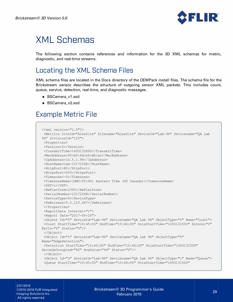
XML SchemasThe following section contains references and information for the 3D XML schemas for metric,diagnostic, and real-time streams.
Locating the XML Schema FilesXML schema files are located in the Docs directory of the OEMPack install files. The schema file for theBrickstream sensor describes the structure of outgoing sensor XML packets. This includes count,queue, service, detection, real-time, and diagnostic messages.
n BSCamera_v1.xsd
n BSCamera_v2.xsd
Example Metric File
<?xml version="1.0"?><Metrics SiteId="AlexSite" Sitename="AlexSite" DeviceId="Lab-96" Devicename="QA Lab96" DivisionId="123"><Properties><Version>2</Version><TransmitTime>1493132892</TransmitTime><MacAddress>00:b0:9d:b9:bb:ec</MacAddress><IpAddress>10.5.1.96</IpAddress><HostName>Cam-12172268</HostName><HttpPort>80</HttpPort><HttpsPort>443</HttpsPort><Timezone>-5</Timezone><TimezoneName>(GMT-05:00) Eastern Time (US Canada)</TimezoneName><DST>1</DST><HwPlatform>2300</HwPlatform><SerialNumber>12172268</SerialNumber><DeviceType>0</DeviceType><SwRelease>5.2.123.467</SwRelease></Properties><ReportData Interval="1"><Report Date="2017-04-25"><Object Id="0" DeviceId="Lab-96" Devicename="QA Lab 96" ObjectType="0" Name="Count"><Count StartTime="10:45:00" EndTime="10:46:00" UnixStartTime="1493131500" Enters="0"Exits="0" Status="0"/></Object><Object Id="1" DeviceId="Lab-96" Devicename="QA Lab 96" ObjectType="5"Name="EdgeDetection"><Detection StartTime="10:45:00" EndTime="10:46:00" UnixStartTime="1493131500"SecondsOccupied="60" AvgValue="49" Status="0"/></Object><Object Id="3" DeviceId="Lab-96" Devicename="QA Lab 96" ObjectType="1" Name="Queue"><Queue StartTime="10:45:00" EndTime="10:46:00" UnixStartTime="1493131500"

Brickstream® 3D Version 5.6
2/21/2019©2015-2019 FLIR IntegratedImaging Solutions Inc.All rights reserved.
Brickstream® 3D Programmer's GuideFebruary 2019
30
AvgQLength="0.00" MaxQLength="0" MinQLength="0" SecondsOpen="0" Exits="0" Status="0"/></Object><Object Id="4" DeviceId="Lab-96" Devicename="QA Lab 96" ObjectType="4"Name="Service"><Service StartTime="10:45:00" EndTime="10:46:00" UnixStartTime="1493131500"NumberServed="0" SecondsOccupied="3" Status="0"/></Object></Report></ReportData></Metrics>
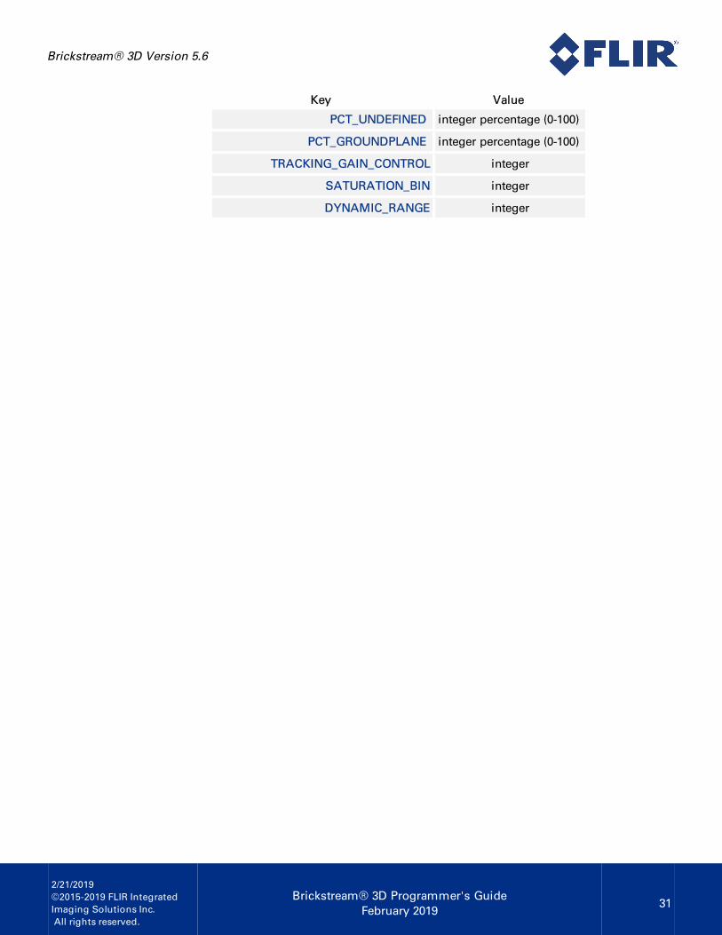
Diagnostic Message Key/Value PairsThe following table shows the key value pairs contained in the diagnostic messages:
Key Value
NUM_OF_REBOOTS count
TOTAL_FRAMES_PROC count
ELAPSED_RESET_SEC seconds
LAST_REBOOT_TIME date/time
LAST_TALLY_RESET_TIME date/time
TOTAL_TIMESYNCS count
TOTAL_FAILED_TIMESYNCS count
TOTAL_DATA_PACKETS_DELIVERED count
FAILED_DATA_PACKETS_DELIVERED count
TOTAL_DATA_PACKETS_INQUEUE count
TOTAL_ALERT_GENERATED count
FOCAL_LENS mm
THREE_D_SCALING_COEFF integer
X_ROTATION degrees
Y_ROTATION degrees
CAMERA_HEIGHT cm
FOCAL_LENGTH pixels
BASE_LINE meters
X_CENTER pixels
Y_CENTER pixels
NUM_OF_REBOOTS count
Brickstream® 3D Version 5.6
2/21/2019©2015-2019 FLIR IntegratedImaging Solutions Inc.All rights reserved.
Brickstream® 3D Programmer's GuideFebruary 2019
31
Key Value
PCT_UNDEFINED integer percentage (0-100)
PCT_GROUNDPLANE integer percentage (0-100)
TRACKING_GAIN_CONTROL integer
SATURATION_BIN integer
DYNAMIC_RANGE integer

Brickstream® 3D Version 5.6
2/21/2019©2015-2019 FLIR IntegratedImaging Solutions Inc.All rights reserved.
Brickstream® 3D Programmer's GuideFebruary 2019
32
Example Diagnostic File
<?xml version="1.0"?><Diags SiteId="AlexSite" Sitename="AlexSite" DeviceId="Lab-96" Devicename="QA Lab 96"DivisionId="123"><Properties><Version>2</Version><TransmitTime>1493133049</TransmitTime><MacAddress>00:b0:9d:b9:bb:ec</MacAddress><IpAddress>10.5.1.96</IpAddress><HostName>Cam-12172268</HostName><HttpPort>80</HttpPort><HttpsPort>443</HttpsPort><Timezone>-5</Timezone><TimezoneName>(GMT-05:00) Eastern Time (US Canada)</TimezoneName><DST>1</DST><DeliveryServerAddress>10.5.1.220</DeliveryServerAddress><DeliveryServerAddress>10.5.1.220</DeliveryServerAddress><TimesyncServerAddress>208.53.158.34</TimesyncServerAddress><HwPlatform>2300</HwPlatform><SerialNumber>12172268</SerialNumber><DeviceType>0</DeviceType><SwRelease>5.2.123.467</SwRelease></Properties><Event TimeStamp="2017-04-25T11:10:48"><LevelId>2</LevelId><EventId>12</EventId><Stat><Key>NUM_OF_REBOOTS</Key><Value>0</Value></Stat><Stat><Key>TOTAL_FRAMES_PROC</Key><Value>6737</Value></Stat><Stat><Key>ELLAPSED_RESET_SEC</Key><Value>921</Value></Stat><Stat><Key>LAST_REBOOT_TIME</Key><Value>04/25/2017 10:55:27</Value></Stat><Stat><Key>LAST_TALLY_RESET_TIME</Key><Value>04/25/2017 10:55:27</Value></Stat><Stat><Key>TOTAL_TIMESYNCS</Key><Value>2</Value></Stat><Stat><Key>TOTAL_FAILED_TIMESYNCS</Key>

Brickstream® 3D Version 5.6
2/21/2019©2015-2019 FLIR IntegratedImaging Solutions Inc.All rights reserved.
Brickstream® 3D Programmer's GuideFebruary 2019
33
<Value>0</Value></Stat><Stat><Key>TOTAL_DATA_PACKETS_DELIVERED</Key><Value>0</Value></Stat><Stat><Key>FAILED_DATA_PACKETS_DELIVERED</Key><Value>0</Value></Stat><Stat><Key>TOTAL_DATA_PACKETS_INQUEUE</Key><Value>0</Value></Stat><Stat><Key>TOTAL_ALERT_GENERATED</Key><Value>0</Value></Stat><Stat><Key>FOCAL_LENS</Key><Value>2.5</Value></Stat><Stat><Key>TRACKING_SHUTTER</Key><Value>427</Value></Stat><Stat><Key>TRACKING_GAIN_CONTROL</Key><Value>3000</Value></Stat><Stat><Key>SATURATION_BIN</Key><Value>160</Value></Stat><Stat><Key>DYNAMIC_RANGE</Key><Value>249</Value></Stat><Stat><Key>CAMERA_HEIGHT</Key><Value>260</Value></Stat><Stat><Key>X_ROTATION</Key><Value>6</Value></Stat><Stat><Key>Y_ROTATION</Key><Value>32</Value></Stat><Stat><Key>PCT_UNDEFINED</Key><Value>15</Value></Stat>

Brickstream® 3D Version 5.6
2/21/2019©2015-2019 FLIR IntegratedImaging Solutions Inc.All rights reserved.
Brickstream® 3D Programmer's GuideFebruary 2019
34
<Stat><Key>PCT_GROUNDPLANE</Key><Value>56</Value></Stat><Stat><Key>RTC_ALARM_STATUS</Key><Value>1</Value></Stat><Stat><Key>FOCAL_LENGTH</Key><Value>144.9805</Value></Stat><Stat><Key>BASE_LINE</Key><Value>0.1195</Value></Stat><Stat><Key>X_CENTER</Key><Value>160.0286</Value></Stat><Stat><Key>Y_CENTER</Key><Value>135.8306</Value></Stat><Message>Heart Beat</Message></Event></Diags>

Brickstream® 3D Version 5.6
2/21/2019©2015-2019 FLIR IntegratedImaging Solutions Inc.All rights reserved.
Brickstream® 3D Programmer's GuideFebruary 2019
35
Diagnostic Heartbeat Message
<?xml version="1.0"?><Diags SiteId="456" Sitename="EngLab" DeviceId="144" Devicename="China144"><Properties><Version>2</Version><TransmitTime>943920000</TransmitTime><MacAddress>00:0b:ab:b4:ea:6e</MacAddress><IpAddress>10.5.1.144</IpAddress><HostName>Cam-0</HostName><HttpPort>80</HttpPort><HttpsPort>443</HttpsPort><Timezone>-5</Timezone><TimezoneName>(GMT-05:00) Eastern Time (US Canada)</TimezoneName><DST>1</DST><DeliveryServerAddress>192.168.1.254</DeliveryServerAddress><DeliveryServerAddress>192.168.1.254</DeliveryServerAddress><TimesyncServerAddress>10.5.1.220</TimesyncServerAddress><HwPlatform>1100</HwPlatform><SerialNumber>3918241</SerialNumber><DeviceType>0</DeviceType><SwRelease>5.2.54.395</SwRelease></Properties><Event TimeStamp="1999-11-29T19:00:00"><LevelId>2</LevelId><EventId>12</EventId><Stat><Key>NUM_OF_REBOOTS</Key><Value>0</Value></Stat><Stat><Key>TOTAL_FRAMES_PROC</Key><Value>234784651</Value></Stat><Stat><Key>ELLAPSED_RESET_SEC</Key><Value>3759566630</Value></Stat><Stat><Key>LAST_REBOOT_TIME</Key><Value>11/16/2016 13:24:26</Value></Stat><Stat><Key>LAST_TALLY_RESET_TIME</Key><Value>11/16/2016 13:24:26</Value></Stat><Stat><Key>TOTAL_TIMESYNCS</Key><Value>11201</Value></Stat><Stat><Key>TOTAL_FAILED_TIMESYNCS</Key><Value>7</Value>

Brickstream® 3D Version 5.6
2/21/2019©2015-2019 FLIR IntegratedImaging Solutions Inc.All rights reserved.
Brickstream® 3D Programmer's GuideFebruary 2019
36
</Stat><Stat><Key>TOTAL_DATA_PACKETS_DELIVERED</Key><Value>0</Value></Stat><Stat><Key>FAILED_DATA_PACKETS_DELIVERED</Key><Value>0</Value></Stat><Stat><Key>TOTAL_DATA_PACKETS_INQUEUE</Key><Value>0</Value></Stat><Stat><Key>TOTAL_ALERT_GENERATED</Key><Value>0</Value></Stat><Stat><Key>FOCAL_LENS</Key><Value>2.0</Value></Stat><Stat><Key>AVERAGE_INTENSITY</Key><Value>84</Value></Stat><Stat><Key>AVERAGE_RED</Key><Value>182</Value></Stat><Stat><Key>AVERAGE_GREEN</Key><Value>161</Value></Stat><Stat><Key>AVERAGE_BLUE</Key><Value>178</Value></Stat><Stat><Key>WB_GAIN</Key><Value>10344</Value></Stat><Stat><Key>WB_GAIN_GREEN0</Key><Value>123</Value></Stat><Stat><Key>WB_GAIN_GREEN1</Key><Value>123</Value></Stat><Stat><Key>WB_GAIN_BLUE</Key><Value>121</Value></Stat><Stat>

Brickstream® 3D Version 5.6
2/21/2019©2015-2019 FLIR IntegratedImaging Solutions Inc.All rights reserved.
Brickstream® 3D Programmer's GuideFebruary 2019
37
<Key>WB_GAIN_RED</Key><Value>41</Value></Stat><Stat><Key>CAMERA_HEIGHT</Key><Value>250</Value></Stat><Stat><Key>X_ROTATION</Key><Value>0</Value></Stat><Stat><Key>Y_ROTATION</Key><Value>0</Value></Stat><Stat><Key>RTC_ALARM_STATUS</Key><Value>1</Value></Stat><Stat><Key>FOCAL_LENGTH</Key><Value>2.0000</Value></Stat><Stat><Key>BASE_LINE</Key><Value>0.0000</Value></Stat><Stat><Key>X_CENTER</Key><Value>160.0000</Value></Stat><Stat><Key>Y_CENTER</Key><Value>120.0000</Value></Stat><Message>Heart Beat</Message></Event></Diags>