Breakers - Wacker Neuson Corporation: login for registered...
50
www.wackergroup.com Breakers EH 27 REPAIR MANUAL 0203793 0504 en 0 2 0 3 7 9 3
Transcript of Breakers - Wacker Neuson Corporation: login for registered...

www.wackergroup.com
Breakers
EH 27
REPAIR MANUAL
0203793
0504 en
0 2 0 3 7 9 3


EH 27 Table of contents
1. Introduction 3
2. General instructions 4
2.1 General ..................................................................................................42.2 Operation ...............................................................................................42.3 Safety checks ........................................................................................62.4 Maintenance ..........................................................................................6
3. Operation 7
3.1 Attaching of tools ...................................................................................73.2 Connection to power source ..................................................................73.3 Suggestions for correct operations ........................................................83.4 Transport to the working area ...............................................................83.5 Function description ..............................................................................9
4. Technical Data 10
5. Jigs and fixtures 11
6. Disassembly / Assembly 12
6.1 Disassembly / Assembly .....................................................................126.2 Hoods - Assembly ...............................................................................146.3 Percussion system - Disassembly .......................................................156.4 Percussion system - Assembly ...........................................................176.5 Motor rotor - Disassembly ...................................................................186.6 Motor rotor - Assembly ........................................................................216.7 Stator - Disassembly ...........................................................................226.8 Stator - Assembly ................................................................................236.9 Gear box - Disassembly ......................................................................246.10 Gear box - Assembly ...........................................................................266.11 Replacement of carbon brushes .........................................................28
1

Table of contents EH 27
6.12 Tool holder replacement ......................................................................297. Electric test procedures 31
8. Wiring diagram 33
9. Sealing compounds, lubricants and adhesives 34
10. Torque settings 38
11. Carbon brushes 39
12. Tool holder 40
12.1 Tool holder replacement ......................................................................40
13. Tools 41
13.1 Forging ................................................................................................4113.2 Hardening ............................................................................................4113.3 Tempering ...........................................................................................4113.4 Grinding (sharpening or honing) ..........................................................41
14. Maintenance schedule 43
15. Troubleshooting 44
2

EH 27
1. Introduction
For your safety and protection from bodily injuries care-fully read, understand and follow the safety instructions in this manual.
All rights, especially the right for copying and distribution are reserved.
Copyright by Wacker Construction Equipment AGNo part of this publication may be reproduced in any form or by any means, electronic or mechanical, inclu-ding photocopying, without express authorization in wri-ting from Wacker Construction Equipment AG.
Any type of reproduction, distribution or saving on data carriers of any type or method not authorized by Wacker represents an infringement of valid copyright and will be prosecuted. We expressly reserve the right to technical modifications - even without express due notice - which aim at impro-ving our machines or their safety standards.
0203793.fm 3

General instructions EH 27
2. General instructions
2.1 General
2.1.1 Independent operating of drilling and breaking hammers may only be carried out by persons who
2.1.2 * are at least 18 years of age,
2.1.3 * are physically and mentally fit for this job,
2.1.4 * have been instructed in drilling and breaking hammers applicationsand have proven their ability for the job to the employer
2.1.5 * may be expected to carry out the job they are charged with carefully.
2.1.6 They must be assigned to the job of operating drilling and breaking hammers by the employer.
2.1.7 Drilling and breaking hammers are to be applied for their proper use. Both the manufacturer’s operating instructions and these safety instructions must be observed.
2.1.8 The persons charged with the operation of these hammers have to be made familiar with the necessary safety measures relating to the machines. In case of extraordinary uses, the employer shall give the necessary additional instructions.
2.1.9 It is possible that these drilling and breaker hammers exceed the admissible sound level rating of 89 dB(A). According to the rules for the prevention of accidents regarding emission of noise, the employees have to wear personal ear protection if the sound level reaches 89 dB(A) or more.
2.2 Operation
2.2.1 The efficacy of operating levers or elements shall not be influenced or rendered ineffective.
2.2.2 Make sure the machines are connected only to electric power supply sources with voltages and frequencies as shown on the name plate.
2.2.3 The operator must switch off drilling and breaking hammers before leaving the machines or going on breaks, disconnect them from the electric power supply source and place them in such a way that they can’t tip or fall over.
2.2.4 Wear safety goggles in order to avoid injuries to the eyes.
2.2.5 We recommend wearing suitable working gloves.
2.2.6 Wear safety shoes while working with drilling and breaking hammers.
2.2.7 Drilling and breaking hammers must always be operated with both hands on the handles provided for this purpose.
0203793.fm 4

EH 27 General instructions
2.2.8 When working with drilling and breaking hammers, especially whencarrying out drilling jobs, the operator has to have a firm stand, particularly when working on scaffoldings, ladders, etc.
2.2.9 Drilling and breaking hammers are to be guided such that hand injuries caused by solid objects are avoided. When carrying out demolition jobs at elevated places, special care is required to prevent the machine or even the operator from falling.
2.2.10 Avoid body contact with earthed (grounded) components. When breaking through walls or during other similar applications make sure that there are no electric wires, gas pipes or such. No one may stay in the room to which the passage is being broken through, as there is danger of injuries being caused by falling wall chunks or even tools.
2.2.11 The tool holder must always be closed during operation. Check tools and tool holders for wear in order to guarantee proper functioning of the tool holder.
2.2.12 Operations with this machine can cause broken-off pieces to be flung away. Therefore no one except the operator is to come near this machine during operations.
2.2.13 Drilling and breaking hammers must be disconnected from the power supply source before going ahead with a tool replacement.
2.2.14 Tools must always be in perfect working conditions.
2.2.15 Never operate this machine in potentially explosive areas.
2.2.16 Never misuse the electric cable to pull or lift the machine. Never use the cable to pull the plug out of the socket.
2.2.17 Electric equipment and materials may only be used if they comply with the operational and local safety requirements. They must be in proper working conditions and this condition is to be maintained.
2.2.18 Never expose electric tools to rain. Never use electric tools in damp or wet environments
0203793.fm 5

General instructions EH 27
2.3 Safety checks
2.3.1 Only operate drilling and breaking hammers with all safety devices installed.
2.3.2 Always check proper function of all control and safety devices before starting operations.
2.3.3 Always check the proper function of the overload clutch of drilling hammers before starting operations.
2.3.4 Check power cables for damages on a regular basis.
2.3.5 The supervisor must be informed immediately in case defects in any of the safety devices or other defects reducing the operational safety of the drilling and breaking hammers are observed.
2.3.6 Always stop operations with the machine if defects jeopardizing the operational safety of the drilling and breaking hammers has been determined.
2.4 Maintenance
2.4.1 Attention:
2.4.2 Only a technically trained person or a skilled technician is allowed to carry out any kind of work on the electric parts of these machines; attention must be paid to the indications given in Chapter 7 as well as to the legal regulations valid in the individual countries.
2.4.3 Only original spare parts may be used. Modifications to this machine, including an adjustment of the maximum motor speed set by the manufacturer, may only be carried out with the express approval of the Wacker Company. All liabilities shall be refused in case of non-observance or non-compliance.
2.4.4 Always disconnect the drilling and breaking hammer from the electric power supply source before carrying out maintenance and repair jobs.
2.4.5 Always reinstall all safety devices properly as soon as the maintenance and repair jobs have been completed.
0203793.fm 6

EH 27 Operation
3. Operation
3.1 Attaching of tools
3.1.1 Rotate latch (9) away from machine at tool holder (11).
3.1.2 Clean tool shank (10) and grease lightly.
3.1.3 Introduce tool all the way to the limit.
3.1.4 Press latch inwards (9) at tool holder (11)..
Only use sharp tools!
Only use tools with tool shank (10) in perfect conditions to avoid possible rebound blows!
3.2 Connection to power source
Before connection make sure that:
3.2.1 The power supply voltage matches the information given on the name plate (12).
3.2.2 The electric hammer is driven by single phase 115 V alternating current.
3.2.3 Check to see if the necessary fuse protection is available in the net. EH 27/115 Volt, 15 Ampere
0203793.fm 7

Operation EH 27
3.2.4 The power supply cable does not include a green-yellow protectiveearthed lead as the electric hammer is double insulated.
3.3 Suggestions for correct operations
3.3.1 Place electric hammer with tool in position on the material to be worked on and then set the machine in motion by pressing the switch lever.
3.3.2 The electric hammer will reach its full percussion power in a few seconds.
3.3.3 Take advantage of the machine’s weight during operation.
3.3.4 Extremely high pressure against the surface being worked on does not improve the hammers performance.
3.3.5 A certain amount of pressure on the machine’s handles is necessary to avoid rebound blows and to guarantee an easy operation.
3.3.6 Place the chisel in such a way that the material to be worked on can be split off. This will help to avoid jamming the chisel and the demolition performance is increased.
3.4 Transport to the working area
Prerequisites:
3.4.1 Always use appropriate lifting devices with a minimum load-bearingcapacity of 66 pounds (30 kg) when transporting the hammer.
3.4.2 Never transport the hammer while it is in operation!
3.4.3 Always lash down the electric hammer when transporting it on the floorof a transport vehicle.
Please observe any additional corresponding rules and regulations valid in your country.
0203793.fm 8

EH 27 Operation
3.5 Function description
Once the switch lever (1) has been actuated the motor (2) drives a gear system (3) and, with it, the crank mechanism (4).
Rotational movements of the crank mechanism journal are converted into rectilinear movements with the help of a connecting rod (5) and a guide piston (6) and transmitted through an air cushion ("pneumatic cushioning") to the striker piston (7).
The striker piston (7) then impacts directly onto the tool’s shank (without the need of an intermediate piston).
0203793.fm 9

Technical Data EH 27
4. Technical Data
EH 27/115
Item no. 0008396 ...
Operating weight (mass)without tool
kg:27
VoltageV:
110 - 127 1~
Power inputkW:
1,8
Current consumptionA:
15
FrequencyHz:
50/60
Percussion ratemin-1:
1050
Special lubricating greasegrease Unirex N2
Shaft for breaking toolsSW 28x152
Drive motortotally insulatedt universal motor
Single stroke impactJ(mkp):
38 (3,8)
The weighted effective acceleration value,determined according to ISO 8662, Part 1
m/s2:
is 6,5
0203793.fm 10

EH 27 Jigs and fixtures
5. Jigs and fixtures
0048901 Bolt 0095514 Bolt0048903 Pipe 0095515 Bolt0203305 Pipe 0095516 Pipe0069626 Bolt 0095517 Pipe0069638 Support 0095518 Pipe0095512 Pipe 0095519 Disc0095513 Bolt 0102712 Bolt
0048901 0048903 0203305 0069626 0069638
0095512 0095513 0095514 0095515 0102712
0095516 0095517 0095518
0095519
0203793.fm 11
Disassembly / Assembly EH 27
6. Disassembly / Assembly
6.1 Disassembly / Assembly
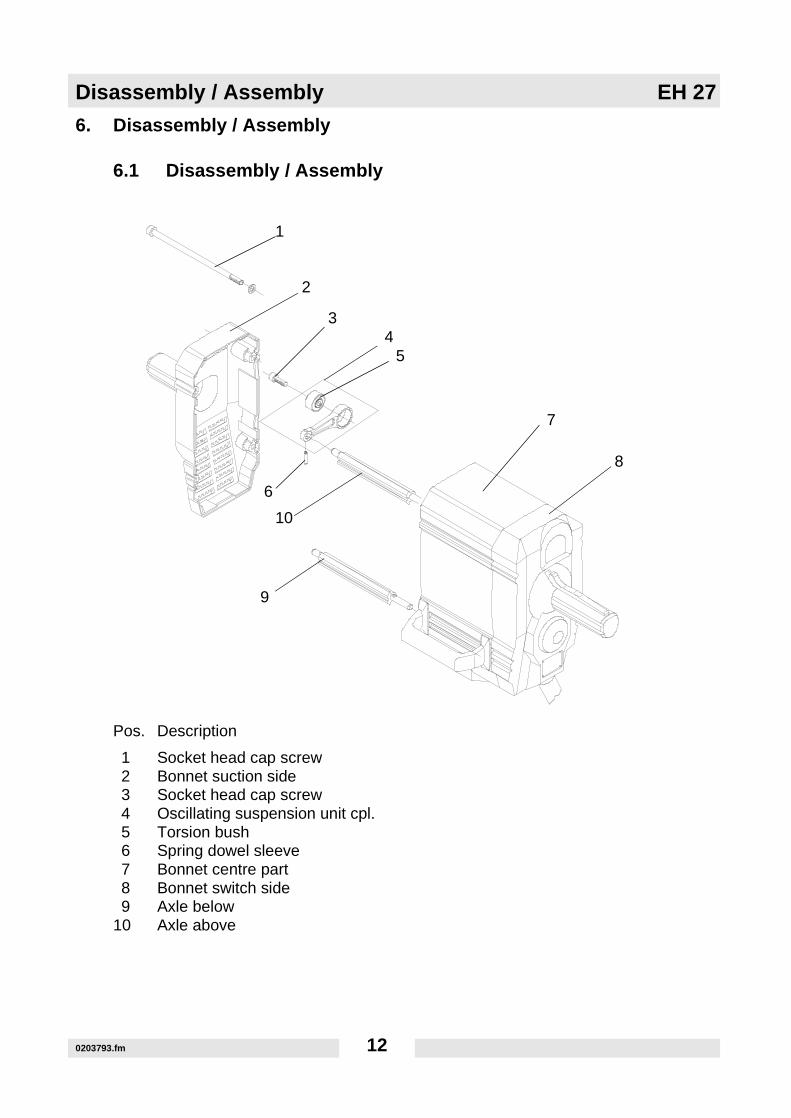
Pos. Description
1 Socket head cap screw2 Bonnet suction side3 Socket head cap screw4 Oscillating suspension unit cpl.5 Torsion bush6 Spring dowel sleeve7 Bonnet centre part8 Bonnet switch side9 Axle below
10 Axle above
1
2
34
5
7
8
9
6
10
0203793.fm 12

EH 27 Disassembly / Assembly
6.1.1 Remove the 4 socket head cap screws (pos. 1) (screw driver TX 40)from the hood on the suction side (pos. 2) and then pull off the hood (pos. 2).
6.1.2 Disconnect the electrical connections before removing the hood (pos. 8) on the switch side.
6.1.3 Remove the hood (pos. 8) on the switch side.
6.1.4 Separate the oscillating suspension unit (pos. 4) from the oscillating shafts (pos. 9 /10) on one side of the machine. For this purpose place oscillating suspension units on e. g. a vise and then expel dowel pins (pos. 6) with a drift pin.
Expel dowel pinwith drift pin
0203793.fm 13
Disassembly / Assembly EH 27
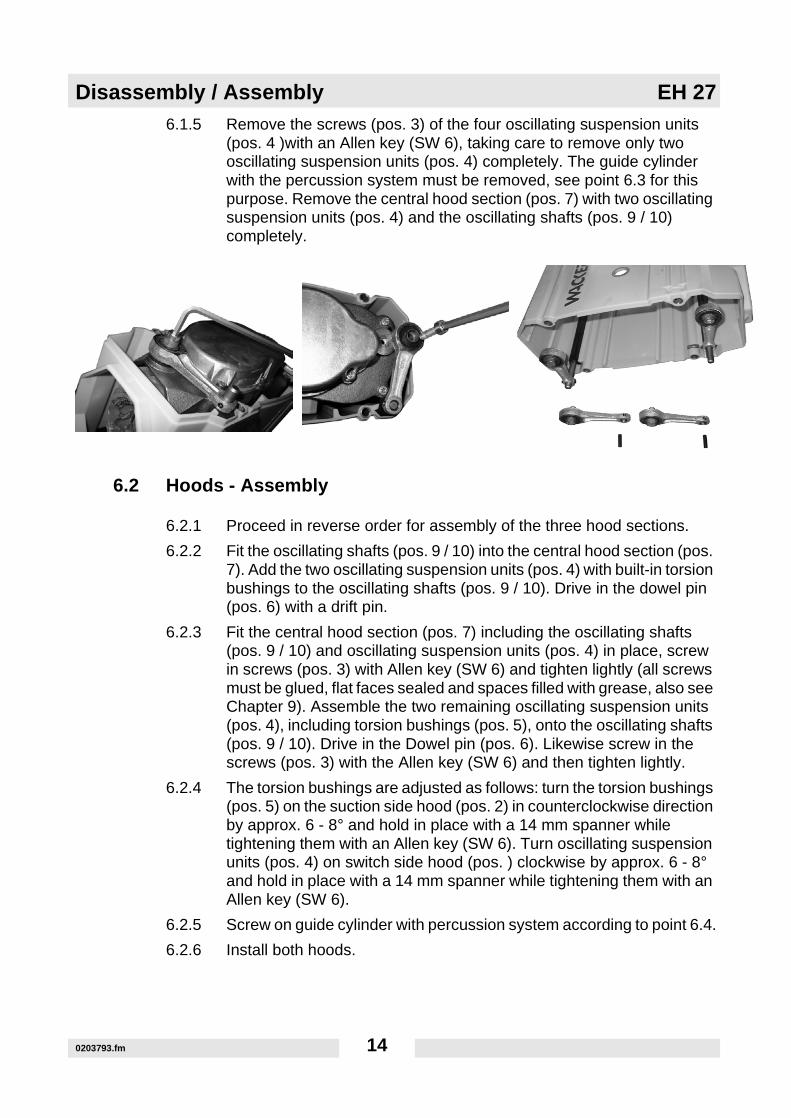
6.1.5 Remove the screws (pos. 3) of the four oscillating suspension units(pos. 4 )with an Allen key (SW 6), taking care to remove only two oscillating suspension units (pos. 4) completely. The guide cylinder with the percussion system must be removed, see point 6.3 for this purpose. Remove the central hood section (pos. 7) with two oscillating suspension units (pos. 4) and the oscillating shafts (pos. 9 / 10) completely.
6.2 Hoods - Assembly
6.2.1 Proceed in reverse order for assembly of the three hood sections.
6.2.2 Fit the oscillating shafts (pos. 9 / 10) into the central hood section (pos. 7). Add the two oscillating suspension units (pos. 4) with built-in torsion bushings to the oscillating shafts (pos. 9 / 10). Drive in the dowel pin (pos. 6) with a drift pin.
6.2.3 Fit the central hood section (pos. 7) including the oscillating shafts (pos. 9 / 10) and oscillating suspension units (pos. 4) in place, screw in screws (pos. 3) with Allen key (SW 6) and tighten lightly (all screws must be glued, flat faces sealed and spaces filled with grease, also see Chapter 9). Assemble the two remaining oscillating suspension units (pos. 4), including torsion bushings (pos. 5), onto the oscillating shafts (pos. 9 / 10). Drive in the Dowel pin (pos. 6). Likewise screw in the screws (pos. 3) with the Allen key (SW 6) and then tighten lightly.
6.2.4 The torsion bushings are adjusted as follows: turn the torsion bushings (pos. 5) on the suction side hood (pos. 2) in counterclockwise direction by approx. 6 - 8° and hold in place with a 14 mm spanner while tightening them with an Allen key (SW 6). Turn oscillating suspension units (pos. 4) on switch side hood (pos. ) clockwise by approx. 6 - 8° and hold in place with a 14 mm spanner while tightening them with an Allen key (SW 6).
6.2.5 Screw on guide cylinder with percussion system according to point 6.4.
6.2.6 Install both hoods.
0203793.fm 14
EH 27 Disassembly / Assembly
6.3 Percussion system - Disassembly
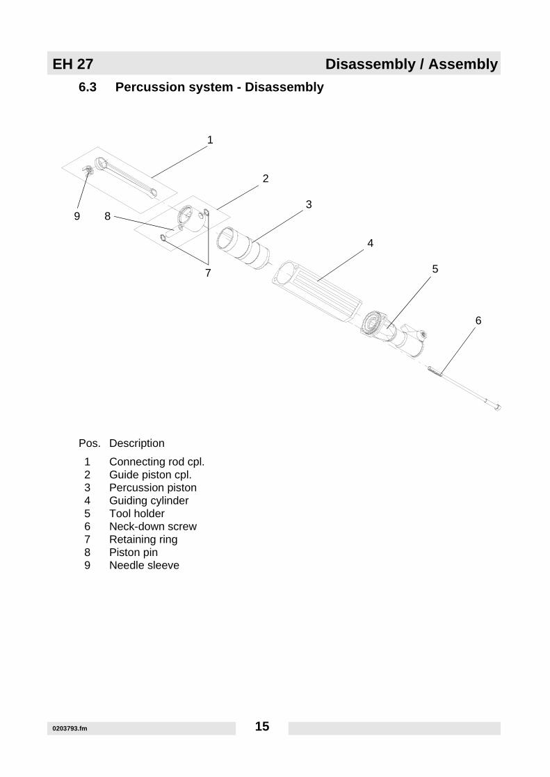
Pos. Description
1 Connecting rod cpl.2 Guide piston cpl.3 Percussion piston4 Guiding cylinder5 Tool holder6 Neck-down screw7 Retaining ring8 Piston pin9 Needle sleeve
1
2
3
4
5
6
7
89
0203793.fm 15

Disassembly / Assembly EH 27
6.3.1 Unscrew the necked-down screws (pos. 6) (SW 17). Remove both thetool holder (pos. 5) and the guide cylinder (pos. 4). Attention: The striker piston (pos. 3) could remain inside the guide cylinder (pos. 4) in certain cases. Remove the striker piston (pos. 3) in such a case. Otherwise simply pull the striker piston (pos. 3) from the guide piston (pos. 2).
Caution: Upper hammer part (hood/gear box) could drop down.
6.3.2 Move connecting rod (pos. 1) to lower position by hand and remove without using any tools. The connecting rod (pos. 1) is only hooked up to the crank gear.
6.3.3 Separate the guide piston (pos. 2) from the connecting rod (pos. 1). To this purpose remove the retaining rings (pos. 7) and press out the piston pin (pos. 8) (support 0069638 / bolt 0069626).
Note: The piston pin could originally have been assembled with avery tight fit. Under all circumstances use both devices(support 0069638 / bolt 0069626) to avoid damaging theguide piston.
0069626
0069638
0203793.fm 16

EH 27 Disassembly / Assembly
6.4 Percussion system - Assembly
6.4.1 Proceed in reverse order for assembly of the percussion system. Press the piston pin (pos. 8) into the guide cylinder (pos. 2) using the fixtures (support 0069638 / bolt 0069626) for this purpose and then connect to the connecting rod (pos. 1). Fit in both retaining rings (pos. 7). Hook the connecting rod (pos. 1) into position at the crank gear. Push the striker piston (pos. 3) over the guide piston (pos. 2). Place the guide cylinder (pos. 4) with tool holder (pos. 5) and necked-down screws (pos. 6) over the striker piston (pos. 3) and fasten to gear box housing. The flat-faced surface must be coated with sealing compound. Tighten the necked-down screws to 55.3 ft. lbs. (75 Nm).
6.4.2 Use the device (bolt 0102712) if the needle sleeve (pos. 9) in the connecting rod needs to be replaced. The device will help you to press out the faulty needle sleeve with a hand press and will help you to press a new one back in.
0203793.fm 17

Disassembly / Assembly EH 27
6.5 Motor rotor - Disassembly
Pos. Description
1 Motor armature2 Air guide3 Socket head cap screw4 Retaining ring5 Retaining ring 6 Cap7 Deep groove ball bearing8 Bearing bracket9 Carbon brush with switch-off device
10 Socket head cap screw11 Cover12 O-ring13 Crank gear
1
2
3
4
56
8
9
10
11
12
137
0203793.fm 18

EH 27 Disassembly / Assembly
6.5.1 Carry out the steps shown in point 6.1 Hoods - Disassembly and 6.3Percussion system - Disassembly before proceeding with the disassembly of the motor (pos. 1). Then loosen the screws of the carbon brushes (pos. 9), lift the spring and remove both the carbon brushes (pos. 9). Take out the retaining ring (pos. 5) from the end shield (pos. 8) and then remove the end shield together with bearing cover (pos. 6). Remove the hexagon socket screws (pos. 3) (SW 6) from the end shield (pos. 8) and then detach the retaining ring (pos. 4). Pull the end shield (pos. 8) from the rotor shaft with a two-jaw puller. Remove the air guide (pos. 2). Unscrew and remove the cover (pos. 11) for the electrical connections.
6.5.2 Note: The cover (pos. 11) is sealed with an O-ring.See instructions inpoint 6.5.7 in case of a defective bearing in the end shield.
6.5.3 Turn the machine around and then unscrew the screws of the gear box cover with an Allen key (SW 5). Remove cover.
Note: The screws have been glued, the gear box cover installedwith sealing compound, thus possibly making it difficult toremove.
End shield
Air guide
0203793.fm 19

Disassembly / Assembly EH 27
6.5.4 Press out rotor with a hand press or carefully tap the rotor shaft with a"soft" drift pin (e. g. brass, bronze). The rotor will move out of the gear box housing together with the stator and the protective sheath.Attention: The protective sheath is an important component of the
protective insulation and should not be damaged!Follow theinstructions below if it is not possible to remove the rotor asa unit with the stator and the protective sheath.
6.5.5 Unscrew and remove the hexagon head screw (SW 10) together with the washer. Pull of the pair of gears with the two-jaw puller.
6.5.6 Remove securing screw (SW 13) and also the washer. Block the crank gear with a piece of wood to loosen the screw. Press out the crank gear with the help of a press and using devices (pipe 0095512 and bolt 0048901). Remove the remaining gear at the same time. Pay attention to the feather key.
6.5.7 Loosen the screws (SW 10) at the gear flange and remove the flange. The gear flange has been positioned with the aid of a dowel pin. A brass drift pin might be required to lift the flange. See point 6.9 / 6.10 Gear - Disassembly / Assembly for gear box repairs.
0048901
0095512
0203793.fm 20

EH 27 Disassembly / Assembly
6.5.8 The motor (pos. 1) can now be removed.
6.5.9 The deep groove ball bearing (pos. 7) in the end shield (pos. 8) must be pressed out with a device (pipe 0203305) and a hand press if it is faulty. The new deep groove ball bearing has to be pressed back in reverse order using a device (pipe 0048903 and a hand press.
6.6 Motor rotor - Assembly
6.6.1 Proceed in reverse order for assembly. Install motor rotor.
6.6.2 Turn machine around and assemble cover (pos. 11) with the O-ring (pos. 12). Tighten fastening screws (pos. 10). Place air guide (pos. 2) in position. Press in end shield (pos. 8) with hand press. Insert retaining ring (pos. 4). Then fill cap (pos. 6) with grease - see Chapter 9, place into end shield (pos. 8) and safeguard with retaining ring (pos. 5). Insert the carbon brushes (pos. 9) into the air guide (pos. 2) and fasten with screws.
6.6.3 Install gear flange paying attention to the dowel pin. Use devices (pipe 0095518 and disc 0095519) to press in the crank gear (pos. 13). Pay attention to even support base.
6.6.4 Place feather key on the shaft of the crank gear (pos. 13) and then press in gear using devices (pipe 0095517 and pipe 0095518). Pay attention to the correct side during assembly.
Note: The feather key will stand out slightly. Insert washer withperforation and secure with fastening screw.
6.6.5 Press in pair of gears with hand press while slightly turning rotor shaft as well as gear on the crank side, thus making it possible to engage the teeth. Secure with hexagon head screw and washer. Screw on gear cover.
6.6.6 Proceed with point 6.4 Percussion system - Assembly and 6.2 Hoods - Assembly.
6.6.7
Note: Seal surface and glue screws.
Dowel pin
0203793.fm 21

Disassembly / Assembly EH 27
6.7 Stator - Disassembly
Pos. Description
1 Crankcase2 O-Ring3 Protective sleeve4 Stator5 Self tapping screw
1
2
3
5
4
0203793.fm 22

EH 27 Disassembly / Assembly
6.7.1 Carry out the steps shown in point 6.1 Hoods - Disassembly and 6.5Motor rotor - Disassembly before proceeding with the disassembly of the stator. Lightly tap on the protective sheath (pos. 3) with the brass drift pin to drive it out of the crankcase (pos. 1).
Attention: The protective sheath (pos. 3) is part of the electricinsulation and should not be damaged!
Loosen and remove both screws (pos. 5) from the inside of the protective sheath (pos. 3) using a Phillips (crosshead) screwdriver. Take the stator (pos. 4) out of the protective sheath (pos. 3).
6.8 Stator - Assembly
Place the stator (pos. 4) inside the protective sheath (pos. 3). Introduce the red / white conductors into the transparent protective hose. In turn introduce this protective hose into the rubber protection. Pay attention while doing so that the red / white conductors are located inside the existing protective sheath’s recess. Make sure that the bore holes in the stator (pos. 4) coincide with the bore holes in the protective sheath (pos. 3). Screw both screws (pos. 5) into the bore holes of the stator (pos. 4) and connect with the protective sheath (pos. 3). Place O-ring (pos. 2) on protective sheath (pos. 3).
6.8.1 Insert the protective sheath (pos. 3) with the stator (pos. 4) and the O-ring (pos. 2) inside the crankcase and press down all the way down to the limit. Insert the rubber protection with the cables into the recess of the crankcase (pos. 1).
6.8.2 Proceed with point 6.6 Rotor - Assembly and then 6.2 Hoods - Assembly.
transparent protective hose Rubber protection
recess in crankcase
red / white conductors
0203793.fm 23

Disassembly / Assembly EH 27
6.9 Gear box - Disassembly
Pos. Description Pos. Description
1 Gear box cover 14 Needle sleeve2 Hex. head cap screw 15 O-Ring3 Washer 16 Retaining ring 4 Gear wheel 17 Supporting washer5 Ring 18 Deep groove ball bearing6 Ring 19 Deep groove ball bearing7 Needle bearing 20 Retaining ring8 Felt ring 21 Gear wheel9 Spring dowel sleeve 22 Fitting key
10 Hex. head cap screw 23 Washer11 Gear case flange 24 Hex. head cap screw12 Crankcase 25 Socket head cap screw 13 Crank gear 26 Socket head cap screw
1
2 3
4
5 6
7 8
9 10
11
12
13
1415
1617
18
192021
2223
24
25
26
0203793.fm 24
EH 27 Disassembly / Assembly
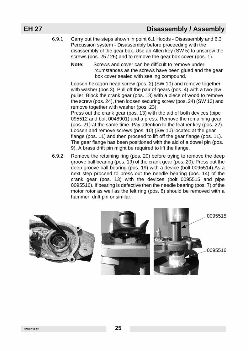
6.9.1 Carry out the steps shown in point 6.1 Hoods - Disassembly and 6.3Percussion system - Disassembly before proceeding with the disassembly of the gear box. Use an Allen key (SW 5) to unscrew the screws (pos. 25 / 26) and to remove the gear box cover (pos. 1).
Note: Screws and cover can be difficult to remove underircumstances as the screws have been glued and the gear box cover sealed with sealing compound.
Loosen hexagon head screw (pos. 2) (SW 10) and remove together with washer (pos.3). Pull off the pair of gears (pos. 4) with a two-jaw puller. Block the crank gear (pos. 13) with a piece of wood to remove the screw (pos. 24), then loosen securing screw (pos. 24) (SW 13) and remove together with washer (pos. 23). Press out the crank gear (pos. 13) with the aid of both devices (pipe 095512 and bolt 0048901) and a press. Remove the remaining gear (pos. 21) at the same time. Pay attention to the feather key (pos. 22). Loosen and remove screws (pos. 10) (SW 10) located at the gear flange (pos. 11) and then proceed to lift off the gear flange (pos. 11). The gear flange has been positioned with the aid of a dowel pin (pos. 9). A brass drift pin might be required to lift the flange.
6.9.2 Remove the retaining ring (pos. 20) before trying to remove the deepgroove ball bearing (pos. 19) of the crank gear (pos. 20). Press out thedeep groove ball bearing (pos. 19) with a device (bolt 0095514).As anext step proceed to press out the needle bearing (pos. 14) of thecrank gear (pos. 13) with the devices (bolt 0095515 and pipe0095516). If bearing is defective then the needle bearing (pos. 7) of themotor rotor as well as the felt ring (pos. 8) should be removed with ahammer, drift pin or similar.
0095515
0095516
0203793.fm 25

Disassembly / Assembly EH 27
6.9.3 Remove the retaining ring (pos. 16) and the supporting washer (pos.17) to be able to remove the deep groove ball bearing (pos. 18) at the gear pair (pos. 4). Press out both deep groove ball bearings (pos. 18) under a hand press with the help of the device (bolt 0095513).
6.10 Gear box - Assembly
6.10.1 Prepare the pair of gears for assembly. Place the pair of gears (pos. 4) on a flat surface and press in first needle bearing (pos. 18) with the help of a device (bolt 0095513). Make sure that the open side points upwards (bearing sealing plate outside) and grease well. Then insert both intermediate rings (pos. 5 / 6) and also grease well. Grease second deep groove ball bearing (pos. 18) well and then, using device (bolt 0095513), press in with open side downwards (bearing sealing plate outside). Fit in supporting washer (pos. 17) and secure it with the retaining ring (pos. 16).
6.10.2 Prepare the gear flange for assembly. Immerse felt ring (pos. 8) in oil and then press into recess. Then on top press in the needle bearing (pos. 7) on the rotor side with the help of a device (bolt 0095514). Then press in the needle sleeve (pos. 14) on the crank gear side with a device (bolt 0095515). Place gear flange (pos. 11) on top in an horizontal position! In the last place press in the deep groove ball bearing (pos. 19) on the crank gear side using a device (bolt 0095514). Install retaining ring (pos. 20). Insert dowel pin (pos. 9).
6.10.3 Fasten gear flange (pos. 11) with O-ring (pos. 15) to the crankcase (pos. 12) and fix with dowel pin (pos. 9).
0095513
0203793.fm 26
EH 27 Disassembly / Assembly
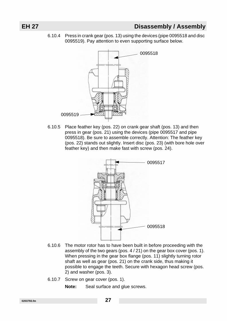
6.10.4 Press in crank gear (pos. 13) using the devices (pipe 0095518 and disc0095519). Pay attention to even supporting surface below.
6.10.5 Place feather key (pos. 22) on crank gear shaft (pos. 13) and then press in gear (pos. 21) using the devices (pipe 0095517 and pipe 0095518). Be sure to assemble correctly. Attention: The feather key (pos. 22) stands out slightly. Insert disc (pos. 23) (with bore hole over feather key) and then make fast with screw (pos. 24).
6.10.6 The motor rotor has to have been built in before proceeding with the assembly of the two gears (pos. 4 / 21) on the gear box cover (pos. 1). When pressing in the gear box flange (pos. 11) slightly turning rotor shaft as well as gear (pos. 21) on the crank side, thus making it possible to engage the teeth. Secure with hexagon head screw (pos. 2) and washer (pos. 3).
6.10.7 Screw on gear cover (pos. 1).
Note: Seal surface and glue screws.
0095518
0095519
0095517
0095518
0203793.fm 27

Disassembly / Assembly EH 27
6.11 Replacement of carbon brushes
6.11.1 Replace the carbon brushes if the surface has worn unevenly, if the length is less than ½" (12 mm) or if the electric cut-off device has been activated.
6.11.2 Carry out the steps shown in point 6.1 Hoods - Disassembly before proceeding with the a control or replacement of the carbon brushes.
6.11.3 Then unscrew and remove the screws holding the carbon brushes, lift the spring and remove both carbon brushes.
6.11.4 Find required information on the carbon brushes in Chapter 11.
6.11.5 Install carbon brushes in the carbon brush holders, place spring on top and then secure by tightening screws.
6.11.6 Carry out point 6.2 Hoods - Assembly as the next step..
0203793.fm 28

EH 27 Disassembly / Assembly
6.12 Tool holder replacement
Pos. Description
1 Guiding cylinder2 Tool holder3 Neck-down screw
1
2
3
0203793.fm 29

Disassembly / Assembly EH 27
6.12.1 Loosen and pull out the necked-down screws (pos. 3) (SW 17).Attention: The guide cylinder (pos. 1) is also fastened with the samenecked-down screws (pos. 3).
6.12.2 Replace the old tool holder (pos. 2) by a new one and then push thenecked-down screws (pos. 3) through the tool holder (pos. 2) as wellas the guide cylinder (pos. 1) and assemble. The sealing surface guidecylinder --gear box must be sealed (see Chapter 9). Tighten thenecked-down screws with 55.3 ft. lbs. (75 Nm).
6.12.3 Place the tool holder such that the tool holder catch is on the same sideas the supplementary handle.
0203793.fm 30

EH 27 Electric test procedures
7. Electric test procedures
This electric hammer is double insulated and does therefore not require the green/yellow protective (grounding) conductor. The hammer corresponds to the Protection class II.
The following tests are required before, after and during repairs of Wacker electrical devices according to DIN VDE 0701 and VDE 0113 standards:
1. Visual inspection2. Insulation resistance measurement3. Electric strength inspection4. Operational inspection
(DIN= German Institute for standardization)(VDE= Association of German Electrotechnical Engineers)
Detailed explanation as follows:Relating to 1. Visual inspection: Attention should be paid to see that the safety of primarily important parts of the machine are neither visually damaged nor obviously unsuitable for the machine. Such parts are for example the housing with cover, cover and electric connection points. All operating materials related and belonging to the machine must be on hand. Particularly the housing of machines of the protection class II (double insulated) must not be damaged under any circumstances. Flexible power cords, even factory-provided equipment power cords, must be inspected for external defects or faults. Additionally the machine must carry the required inscriptions, e. g. a name plate.
Relating to 2. Insulation resistance measurement with SK 21 measuring instrument (tester):Connect the machine to be examined to the test leads.The insulation measurement must be carried out after the repair and before the machine is connected to the electric control panel. The measured value may not fall below the prescribed value.For machines of the protection class II (double insulated) = 2 megohm.The measuring instrument must show higher values!
Relating to 3. Electric strength inspection with measuring instrument UH 270:Carry out all the tests with switch in "on" position.The test must be carried out with high-voltage for approx. 3 seconds between metal parts open to touch and the power cord (plug pins or connector prongs).Test before repair and before connection to the electric control panel:For machines of the protection class II with 3,500 volts.
During the repair, after cleaning; before assembly:Stator: Between metal stack and connection to windings 1000 VoltMotor rotor: Between metal stack and commutator 1000 Volt
Between metal stack and shaft 1000 VoltAfter the repair and before connection to the electric control panel:For machines of the protection class II with 3,500 volts.
0203793.fm 31

Electric test procedures EH 27
Relating to 4. Operational inspection: An operational inspection must be carried out following the repair. The machine must be operated according to specifications, such as described in the operator’s manual. The current drawn must be controlled. All required inscriptions must be on the machine after a repair.Final acceptance:Pay close attention to local legal rules and regulations / specifications.
0203793.fm 32

EH 27 Wiring diagram
8. Wiring diagram
1. Motor2. Cover with terminal board3. Switch4. Plug
0203793.fm 33

Sealing compounds, lubricants and adhesives EH 27
9. Sealing compounds, lubricants and adhesives
sealed withOmni Visc 1002
tightened with 55.3 ft.lbs. (75Nm)
glued withsecured with screw-securing varnish
screw-securing varnishsecured with
Omnifit 100Mretainingcompound
0203793.fm 34
EH 27 Sealing compounds, lubricants
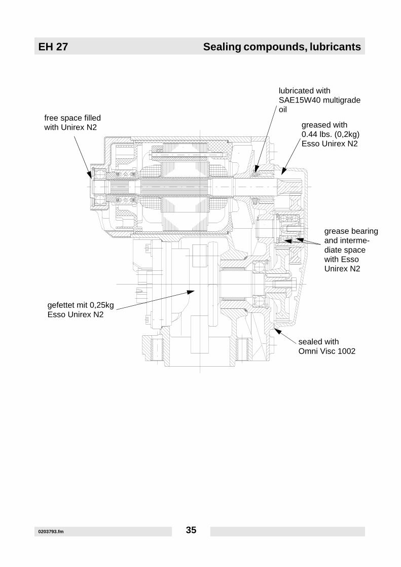
g
lubricated with SAE15W40 multigrade
greased with 0.44 lbs. (0,2kg)
grease bearinand interme-diate spacewith Esso
sealed withOmni Visc 1002
free space filled with Unirex N2
gefettet mit 0,25kgEsso Unirex N2
oil
Esso Unirex N2
Unirex N2
0203793.fm 35

Sealing compounds, lubricants and adhesives EH 27
Grease: ESSO Unirex N2Oil: SAE 15W40Gear flange and gears: Dip felt ring in oil. Immerse felt ring in oil and then press into recess. Grease needle and deep groove ball bearings.Gear box:Grease gear box, entire hollow space with approx. 7 ounces (0,2 Kg) of grease
Crank case:Grease crank case with approx. 8.8 ounces (0,25 Kg).
0203793.fm 36

EH 27 Sealing compounds, lubricants
Percussion system:Slightly grease the percussion system as follows: guide piston on the outside, striker piston inside and outside, guide piston on the inside. Too much grease will lead to a caking of the moving parts. The percussion system should be disassembled, cleaned and regreased after approx. 80 running hours.Only introduce tools with clean lightly greased tool shanks into the tool holder. Grease catch lightly. Fill free space between motor rotor and bearing cap with grease.Adhesive (bonding compound):Glue in all screws with Omni Fit 100 M.Sealing compound:Use Omni Visc 1002 as a sealing compound. Both sealing faces of the crank case and the guide cylinder as well as the crank case and the gear box cover must be sealed..Screw securing:Both screws at the carbon brushes as well as the electric connections under the cover are secured with screw securing varnish UN 1263.
0203793.fm 37

Torque settings EH 27
10. Torque settingsTyp
ft lb Nm ft lb Nm ft lb Nm inch Met. inch Met.
M3 *11 1.2 *14 1.6 *19 2.1 7/32 5.5 - 2.5
M4 *26 2.9 *36 4.1 *43 4.9 9/32 7 - 3
M5 *53 6.0 6 8.5 7 10 5/16 8 - 4
M6 7 10 10 14 13 17 - 10 - 5
M8 18 25 26 35 30 41 1/2 13 - 6
M10 36 49 51 69 61 83 11/16 17 - 8
M12 63 86 88 120 107 145 3/4 19 - 10
M14 99 135 140 190 169 230 7/8 22 - 12
M16 155 210 217 295 262 355 15/16 24 - 14
M18 214 290 298 405 357 485 1-1/16 27 - 14
M20 302 410 427 580 508 690 1-1/4 30 - 17
* = in lb Typ
ft lb Nm ft lb Nm inch Met. ft lb Nm inch Met.
No. 4 *6 0.7 *9 1.0 1/4 - *12 1.4 3/32 -
No. 6 *12 1.4 *17 1.9 5/16 8 *21 2.4 7/64 -
No. 8 *22 2.5 *31 3.5 11/32 9 *42 4.7 9/64 -
No. 10 *32 3.6 *45 5.1 3/8 - *60 6.8 5/32 -
1/4 6 8 9 12 7/16 - 12 16 3/16 -
5/16 13 18 19 26 1/2 13 24 33 1/4 -
3/8 23 31 33 45 9/16 - 43 58 5/16 -
7/16 37 50 52 71 5/8 16 69 94 3/8 -
1/2 57 77 80 109 3/4 19 105 142 3/8 -
9/16 82 111 115 156 13/16 - 158 214 - -
5/8 112 152 159 216 15/16 24 195 265 1/2 -
3/4 200 271 282 383 1-1/8 - 353 479 5/8 -
1 ft lb = 1.357 Nm 1 inch = 25.4 mm
0203793.fm 38

EH 27 Carbon brushes
11. Carbon brushes
80 hours maintenance intervalCarbon brush replacement if:
- the surface of the brush has worn unevenly.- the length of the brush is less than ½" (12 mm).- the electric cut-off device of the brush has been activated.
The built-in carbon brushes were developed and tested especially for this hammer. Only use original Wacker EH 27 carbon brushes. Carbon brushes by other manufacturers have a negative influence on the electric motor's characteristics, even though the dimensions are the same.The item number for the carbon brushes is 0106741, always order two and replace simultaneously.
0203793.fm 39

Tool holder EH 27
12. Tool holder
12.1 Tool holder replacement
12.1.1 0.0.1 The hammer’s performance is strongly influenced by the conditions of the tools being used. This is the reason why it is recommendable to use only tools that are sharp and in perfect working order. Unsuitable or blunt tools can lead to overloads and consequent damaging of the hammer.
12.1.2 0.0.2 Compare worn out shanks with new tool holders and vice versa. The corresponding part must be replaced if the deflection is more than 3/8" (10 mm) at 15¾" (400 mm).
12.1.3 0.0.1 Loosen and remove the necked-down screws (SW 17). Remove the tool holder. Fit on new tool holder. Tighten the necked-down screws with 55.3 ft. lbs. (75 Nm)
400 mm
10 m
m
0203793.fm 40

EH 27 Tools
13. Tools
13.1 Forging
Care should be taken to heat only that part of the tool that needs to be forged. Moreover, it is important that the heat be constantly watched and increased slowly, as heat cracks are otherwise likely to occur on hardened tools.
Forging temperature: 1,470 - 1,830° F (800 - 1.000° C) bright cherry-red to yellow
The tool should be forged within above limits and should, if necessary, be reheated repeatedly. A temperature below 1,470° F (800° C) may lead to tension cracks, whereas temperatures exceeding 1,830° F (1.000° C) will overheat the steel and make it useless. The tool should be quenched in an ash or sand box after forging. Do not proceed to harden the tools while they are still warm from forging.
13.2 Hardening
Heat point or blade in the direction of the tool shank up to a cherry almost light red color 1,436 - 1,490° F (780 - 810° C) over the shortest distance possible of ½ approx. 1 and 1/5 to 1 ½" (30 - 40 mm), then quench in water with approx. 68° F (20° C), while constantly moving the tool up and down in the water.
13.3 Tempering
Polish blade with an abrasive (emery) cloth. Warm shaft to approx. 428° F (220° C). The stored heat will wander towards the blade and stain it.
Tempering color:
golden brown - for soft stones
white yellow - for hard stone
Immediately quench the tool in water when the tempering color has been reached.
13.4 Grinding (sharpening or honing)
Sharpen the insert tools on a grinding wheel, best of all sandstone, under sufficient cooling water. The edges should not be allowed to turn blue, as this would have a negative effect on the hardness of the tool. Take care to achieve the proper cutting angle. The harder the material to be cut, the greater the angle.
0203793.fm 41

Tools EH 27
Moil point Flat chisel Blank Plaster chisel
Spade Pointed spade Asphalt cutter
0203793.fm 42

EH 27 Maintenance schedule
14. Maintenance schedule
Striker and guide piston wear
Dimensional specifications for wear limits of the striker piston inside / guide piston outside are not possible as these are in the range of the hundredths and because out-of-roundness also plays a role. Examination of both parts in grease-free conditions: A noticeable resistance has to be felt in the lower area due to the air cushion that has built up. Greased components react better as the grease film acts as an additional seal.
Check all external screwed connections for a tight fit approx. 8 hours after first operation.
Component Maintenance work Maintenance interval
Power cord Check for perfect condition - replace if cord is defective. dailyProtective hood Ventilation openings free of dirt - clean if necessary.Tools Examination of tool shanks and blades
- sharpen, forge if necessary or replace.
Motor head Regrease via grease nipple. 20 h( see Technical Specifications)
Carbon brushes Check for wear, replace if remaining length less 80 hthan ½" (12 mm) in spite of electric cut-off device.
Motor head Check tight fit of all screws - retighten if necessary.Percussion system Disassemble, clean.
Regrease with 15 - 20 pump strokes (squirts) with 20 hgrease piston press A180 (item number 0066163).
Tool holder Check for wear.
Electric hammer Maintenance at WACKER Service Station. 300 h
0203793.fm 43

Troubleshooting EH 27
15. Troubleshooting
The hammer does not hit (strike) as usual?Overgreasing the percussion system or lack of grease tends to lead to a modification of the impact properties (see Chapter 9 and 11).
The synthetic material inside the tool holder has been destroyed. What should be done?The machine can be operated under these conditions for a short period of time. Then remove the remaining synthetic material and replace by O-ring 51x9 (item number 0065102).How can one find out if the rotor and stator are faulty?An induction comparison test with the PI 5000 testing instrument must be carried out in the first place as follows: The induction test to determine if there is an interruption in either stator windings or in the commutator of the rotor is carried out with the PI 5000 tester. A visual control of both parts does not necessarily have to have shown a defect. The rotor of the EH 27 can be checkedwhen disassembled with the help of a testing instrument and an armature tester (growler). The test takes place as described in the users manual of the tester. The needle should only defect slightly once the parameters (values) have been adjusted and when measuring from lamina to lamina all the way around the circumference of the commutator..
0203793.fm 44

EH 27 Troubleshooting
The control of the stator is carried out exactly the same way. Here the entrance or, alternately, the exit of each coil is measured. Keep in mind that the coils all must have the same value.A high-voltage test is carried out in the second place:
High-voltage test of rotor:
The high-voltage dielectric strength test of the rotors is done with a voltage of 1000 volts. Measurements take place between the shaft and the metal stack as well as between the metal stack and the commutator.
.
0203793.fm 45

Troubleshooting EH 27
High-voltage testing of stator:The high-voltage dielectric strength test of stators is done with a voltage of 1000 volts. Measurements take place between the coil connection and the metal stack.
The scale needle must remain in the green area during the high-voltage testing. The stator has an insulation defect or, as the case may be, an accidental earth contact if the needle moves down. This means that the stator or rotor is defective.
0203793.fm 46


Wacker Construction Equipment AG · Preußenstraße 41 · D-80809 München · Tel.: +49-(0)89-354 02 - 0 · Fax: +49 - (0)89-354 02-390Wacker Corporation · P.O. Box 9007 · Menomonee Falls, WI 53052-9007 · Tel. : +1-(1)(262) 255-0500 · Fax: +1-(1)(262) 255-0550 · Tel. : (800) 770-0957Wacker Asia Pacific Operations · Sunley Center, Unit 912, 9/F · 9 Wing Qin Street, Kwai Chung, N.T. · Hong Kong · Tel. + 852 2406 60 32 · Fax: + 852 2406 60 21