
BRD4183A EFR32MG22 Reference Manual
19
EFR32MG22 2.4 GHz 6 dBm Radio Board BRD4183A Reference Manual The BRD4183A Wireless Gecko Radio Board enables developers to develop Blue- tooth ® Low Energy applications. The board contains a 2.4 GHz Wireless Gecko Wire- less System-on-Chip and is optimized for operating at 6 dBm output power. Radiated and conducted testing is supported with the on-board printed antenna and UFL connec- tor. The BRD4183A Wireless Gecko Radio Board plugs into the Wireless Starter Kit Main- board, which is included with the Wireless Gecko Starter Kit and gives access to debug interface, Virtual COM port, packet trace, button, LED, and additional features from ex- pansion boards. With the supporting Simplicity Studio suite of tools, developers can take advantage of graphical wireless application development and visual energy profiling and optimization. The board also serves as an RF reference design for applications targeting 2.4 GHz wireless operation with 6 dBm output power. RADIO BOARD FEATURES • Wireless SoC: EFR32MG22C224F512IM32 • CPU core: ARM ® Cortex ® -M33 • Flash memory: 512 kB • RAM: 32 kB • Operation frequency: 2.4 GHz • Transmit power: 6 dBm • Integrated PCB antenna, UFL connector (optional) • Crystals for LFXO and HFXO: 32.768 kHz and 38.4 MHz • 8 Mbit low-power serial flash for over-the- air updates This document contains a brief introduction and description of the BRD4183A Radio Board features, focusing on the RF sections and performance. silabs.com | Building a more connected world. Rev. 1.00
Transcript of BRD4183A EFR32MG22 Reference Manual

EFR32MG22 2.4 GHz 6 dBm Radio BoardBRD4183A Reference Manual
The BRD4183A Wireless Gecko Radio Board enables developers to develop Blue-tooth® Low Energy applications. The board contains a 2.4 GHz Wireless Gecko Wire-less System-on-Chip and is optimized for operating at 6 dBm output power. Radiatedand conducted testing is supported with the on-board printed antenna and UFL connec-tor.
The BRD4183A Wireless Gecko Radio Board plugs into the Wireless Starter Kit Main-board, which is included with the Wireless Gecko Starter Kit and gives access to debuginterface, Virtual COM port, packet trace, button, LED, and additional features from ex-pansion boards. With the supporting Simplicity Studio suite of tools, developers can takeadvantage of graphical wireless application development and visual energy profiling andoptimization. The board also serves as an RF reference design for applications targeting2.4 GHz wireless operation with 6 dBm output power.
RADIO BOARD FEATURES
• Wireless SoC:EFR32MG22C224F512IM32• CPU core: ARM® Cortex®-M33• Flash memory: 512 kB• RAM: 32 kB
• Operation frequency: 2.4 GHz• Transmit power: 6 dBm• Integrated PCB antenna, UFL connector
(optional)• Crystals for LFXO and HFXO: 32.768 kHz
and 38.4 MHz• 8 Mbit low-power serial flash for over-the-
air updates
This document contains a brief introduction and description of the BRD4183A RadioBoard features, focusing on the RF sections and performance.
silabs.com | Building a more connected world. Rev. 1.00

Table of Contents1. Introduction . . . . . . . . . . . . . . . . . . . . . . . . . . . . . . . . 4
2. Radio Board Connector . . . . . . . . . . . . . . . . . . . . . . . . . . . 52.1 Introduction . . . . . . . . . . . . . . . . . . . . . . . . . . . . . . . 5
2.2 Radio Board Connector Pin Associations . . . . . . . . . . . . . . . . . . . . . 5
3. Radio Board Block Summary . . . . . . . . . . . . . . . . . . . . . . . . . 63.1 Introduction . . . . . . . . . . . . . . . . . . . . . . . . . . . . . . . 6
3.2 Radio Board Block Diagram . . . . . . . . . . . . . . . . . . . . . . . . . 6
3.3 Radio Board Block Description . . . . . . . . . . . . . . . . . . . . . . . . 63.3.1 Wireless MCU. . . . . . . . . . . . . . . . . . . . . . . . . . . . . 63.3.2 LF Crystal Oscillator (LFXO) . . . . . . . . . . . . . . . . . . . . . . . . 63.3.3 HF Crystal Oscillator (HFXO). . . . . . . . . . . . . . . . . . . . . . . . 63.3.4 Matching Network for 2.4 GHz . . . . . . . . . . . . . . . . . . . . . . . 63.3.5 UFL Connector . . . . . . . . . . . . . . . . . . . . . . . . . . . . 73.3.6 Radio Board Connectors . . . . . . . . . . . . . . . . . . . . . . . . . 73.3.7 Inverted-F Antenna . . . . . . . . . . . . . . . . . . . . . . . . . . . 73.3.8 Serial EEPROM . . . . . . . . . . . . . . . . . . . . . . . . . . . . 7
4. RF Section . . . . . . . . . . . . . . . . . . . . . . . . . . . . . . . . 84.1 Introduction . . . . . . . . . . . . . . . . . . . . . . . . . . . . . . . 8
4.2 Schematic of the RF Matching Network. . . . . . . . . . . . . . . . . . . . . . 84.2.1 Description of the 2.4 GHz RF Matching . . . . . . . . . . . . . . . . . . . . 8
4.3 Bill of Materials for the 2.4 GHz Matching . . . . . . . . . . . . . . . . . . . . . 8
4.4 Inverted-F Antenna . . . . . . . . . . . . . . . . . . . . . . . . . . . . 9
5. Mechanical Details . . . . . . . . . . . . . . . . . . . . . . . . . . . . 10
6. EMC Compliance . . . . . . . . . . . . . . . . . . . . . . . . . . . . . .116.1 Introduction . . . . . . . . . . . . . . . . . . . . . . . . . . . . . . .11
6.2 EMC Regulations for 2.4 GHz . . . . . . . . . . . . . . . . . . . . . . . . .116.2.1 ETSI EN 300-328 Emission Limits for the 2400-2483.5 MHz Band . . . . . . . . . . .116.2.2 FCC15.247 Emission Limits for the 2400-2483.5 MHz Band . . . . . . . . . . . . .116.2.3 Applied Emission Limits for the 2.4 GHz Band . . . . . . . . . . . . . . . . . .11
7. RF Performance . . . . . . . . . . . . . . . . . . . . . . . . . . . . . 127.1 Conducted Power Measurements . . . . . . . . . . . . . . . . . . . . . . .12
7.1.1 Conducted Power Measurements with Unmodulated Carrier . . . . . . . . . . . . .127.1.2 Conducted Power Measurements with Modulated Carrier . . . . . . . . . . . . . .13
7.2 Radiated Power Measurements . . . . . . . . . . . . . . . . . . . . . . . .137.2.1 Maximum Radiated Power Measurements . . . . . . . . . . . . . . . . . . .147.2.2 Antenna Pattern Measurements. . . . . . . . . . . . . . . . . . . . . . .14
8. EMC Compliance Recommendations . . . . . . . . . . . . . . . . . . . . . 158.1 Recommendations for 2.4 GHz ETSI EN 300-328 Compliance . . . . . . . . . . . . . .15
silabs.com | Building a more connected world. Rev. 1.00 | 2

8.2 Recommendations for 2.4 GHz FCC 15.247 Compliance . . . . . . . . . . . . . . . .15
9. Board Revision History . . . . . . . . . . . . . . . . . . . . . . . . . . 16
10. Errata. . . . . . . . . . . . . . . . . . . . . . . . . . . . . . . . . 17
11. Document Revision History . . . . . . . . . . . . . . . . . . . . . . . . 18
silabs.com | Building a more connected world. Rev. 1.00 | 3

1. Introduction
The EFR32™ Wireless Gecko Radio Boards provide a development platform (together with the Wireless Starter Kit Mainboard) for theSilicon Labs EFR32 Wireless Gecko Wireless System-on-Chips and serve as reference designs for the matching network of the RFinterface.
The BRD4183A Radio Board is designed to operate in the 2400-2483.5 MHz band with the RF matching network optimized for operat-ing at 6 dBm output power.
To develop and/or evaluate the EFR32 Wireless Gecko, the BRD4183A Radio Board can be connected to the Wireless Starter Kit Main-board to get access to debug interface, Virtual COM port, packet trace, button, LED, and additional features from expansion boards,and also to evaluate the performance of the RF interface.
BRD4183A Reference ManualIntroduction
silabs.com | Building a more connected world. Rev. 1.00 | 4
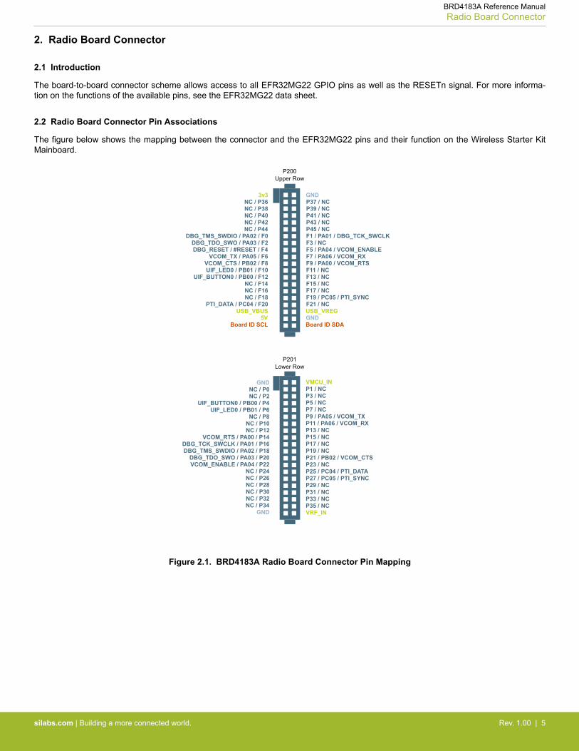
2. Radio Board Connector
2.1 Introduction
The board-to-board connector scheme allows access to all EFR32MG22 GPIO pins as well as the RESETn signal. For more informa-tion on the functions of the available pins, see the EFR32MG22 data sheet.
2.2 Radio Board Connector Pin Associations
The figure below shows the mapping between the connector and the EFR32MG22 pins and their function on the Wireless Starter KitMainboard.
GND
F9 / PA00 / VCOM_RTS
3v3NC / P36
P200Upper Row
NC / P38NC / P40NC / P42NC / P44
DBG_TMS_SWDIO / PA02 / F0
NC / F14UIF_BUTTON0 / PB00 / F12
UIF_LED0 / PB01 / F10VCOM_CTS / PB02 / F8
DBG_RESET / #RESET / F4DBG_TDO_SWO / PA03 / F2
NC / F16
VCOM_TX / PA05 / F6
PTI_DATA / PC04 / F20NC / F18
USB_VBUS5V
Board ID SCLGNDBoard ID SDA
USB_VREG
F7 / PA06 / VCOM_RXF5 / PA04 / VCOM_ENABLEF3 / NCF1 / PA01 / DBG_TCK_SWCLKP45 / NCP43 / NCP41 / NCP39 / NCP37 / NC
F11 / NCF13 / NCF15 / NCF17 / NCF19 / PC05 / PTI_SYNCF21 / NC
GND VMCU_INNC / P0
P201Lower Row
NC / P2UIF_BUTTON0 / PB00 / P4
UIF_LED0 / PB01 / P6
GND VRF_INP35 / NC
P7 / NCP5 / NCP3 / NCP1 / NC
P33 / NCP31 / NCP29 / NCP27 / PC05 / PTI_SYNCP25 / PC04 / PTI_DATAP23 / NCP21 / PB02 / VCOM_CTSP19 / NCP17 / NCP15 / NCP13 / NCP11 / PA06 / VCOM_RXP9 / PA05 / VCOM_TX
NC / P34NC / P32NC / P30NC / P28NC / P26NC / P24
VCOM_ENABLE / PA04 / P22DBG_TDO_SWO / PA03 / P20
DBG_TMS_SWDIO / PA02 / P18DBG_TCK_SWCLK / PA01 / P16
VCOM_RTS / PA00 / P14NC / P12NC / P10NC / P8
Figure 2.1. BRD4183A Radio Board Connector Pin Mapping
BRD4183A Reference ManualRadio Board Connector
silabs.com | Building a more connected world. Rev. 1.00 | 5

3. Radio Board Block Summary
3.1 Introduction
This section gives a short introduction to the blocks of the BRD4183A Radio Board.
3.2 Radio Board Block Diagram
The block diagram of the BRD4183A Radio Board is shown in the figure below.
Inverted-FPCB
Antenna
2.4 GHz RF
UFLConnector
LFCrystal
32.768k
HFCrystal
38.4M
Radio Board
Connectors
I2C
24AA024Serial
EEPROM
MatchingNetwork &
OutputSelection
GPIO
UART
Debug
Packet Trace
AEM
2.4
GH
z R
F
EFR32EFR32Wireless SoC
2.4
GH
z R
F
8 MbitMX25R
Serial Flash
SPI
Figure 3.1. BRD4183A Block Diagram
3.3 Radio Board Block Description
3.3.1 Wireless MCU
The BRD4183A Wireless Gecko Radio Board incorporates an EFR32MG22C224F512IM32 Wireless System-on-Chip featuring 32-bitCortex®-M33 core, 512 kB of flash memory, 32 kB of RAM and a 2.4 GHz band transceiver with output power up to 6 dBm. For addi-tional information on the EFR32MG22C224F512IM32, refer to the EFR32MG22 Data Sheet.
3.3.2 LF Crystal Oscillator (LFXO)
The BRD4183A Radio Board has a 32.768 kHz crystal mounted. For details regarding the crystal configuration, refer to application noteAN0016.2: Oscillator Design Considerations.
3.3.3 HF Crystal Oscillator (HFXO)
The BRD4183A Radio Board has a 38.4 MHz crystal mounted. For details regarding the crystal configuration, refer to application noteAN0016.2: Oscillator Design Considerations.
3.3.4 Matching Network for 2.4 GHz
The BRD4183A Radio Board incorporates a 2.4 GHz matching network which connects the 2.4 GHz RF input/output of theEFR32MG22 to the one on-board printed Inverted-F antenna. The component values were optimized for the 2.4 GHz band RF perform-ance and current consumption with 6 dBm output power.
BRD4183A Reference ManualRadio Board Block Summary
silabs.com | Building a more connected world. Rev. 1.00 | 6
For detailed description of the matching network, see section 4.2.1 Description of the 2.4 GHz RF Matching.
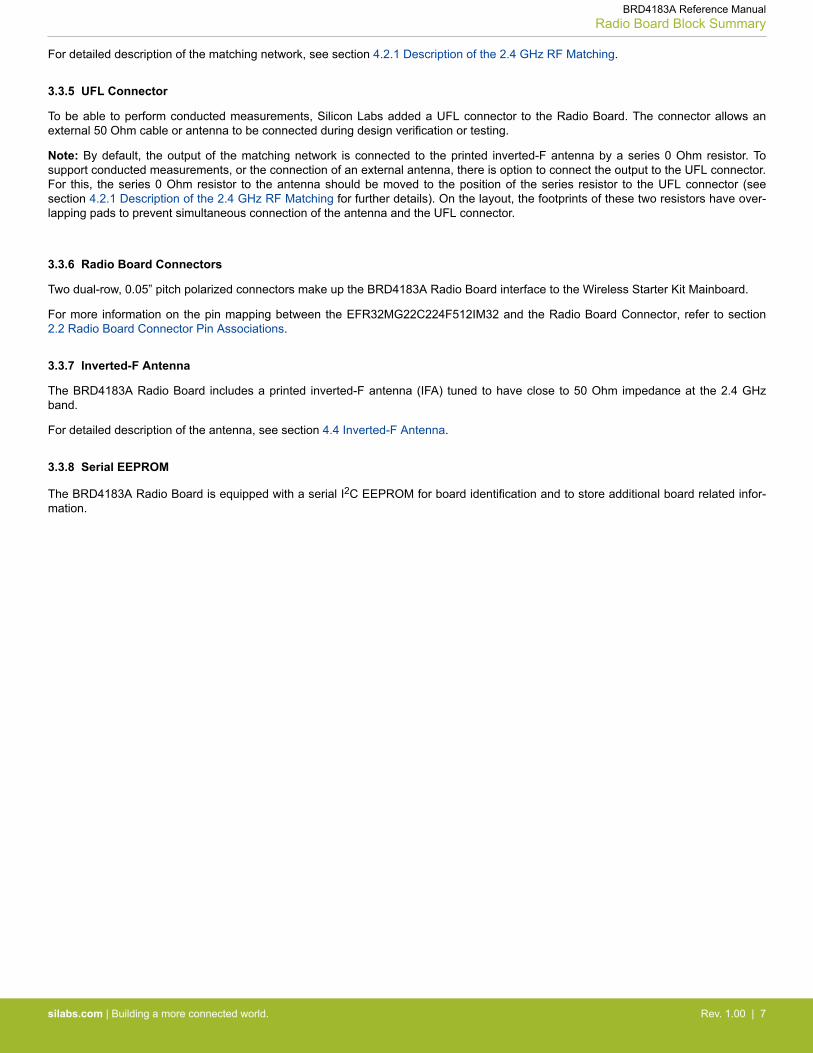
3.3.5 UFL Connector
To be able to perform conducted measurements, Silicon Labs added a UFL connector to the Radio Board. The connector allows anexternal 50 Ohm cable or antenna to be connected during design verification or testing.
Note: By default, the output of the matching network is connected to the printed inverted-F antenna by a series 0 Ohm resistor. Tosupport conducted measurements, or the connection of an external antenna, there is option to connect the output to the UFL connector.For this, the series 0 Ohm resistor to the antenna should be moved to the position of the series resistor to the UFL connector (seesection 4.2.1 Description of the 2.4 GHz RF Matching for further details). On the layout, the footprints of these two resistors have over-lapping pads to prevent simultaneous connection of the antenna and the UFL connector.
3.3.6 Radio Board Connectors
Two dual-row, 0.05” pitch polarized connectors make up the BRD4183A Radio Board interface to the Wireless Starter Kit Mainboard.
For more information on the pin mapping between the EFR32MG22C224F512IM32 and the Radio Board Connector, refer to section2.2 Radio Board Connector Pin Associations.
3.3.7 Inverted-F Antenna
The BRD4183A Radio Board includes a printed inverted-F antenna (IFA) tuned to have close to 50 Ohm impedance at the 2.4 GHzband.
For detailed description of the antenna, see section 4.4 Inverted-F Antenna.
3.3.8 Serial EEPROM
The BRD4183A Radio Board is equipped with a serial I2C EEPROM for board identification and to store additional board related infor-mation.
BRD4183A Reference ManualRadio Board Block Summary
silabs.com | Building a more connected world. Rev. 1.00 | 7
4. RF Section
4.1 Introduction
This section gives a short introduction to the RF section of the BRD4183A Radio Board.
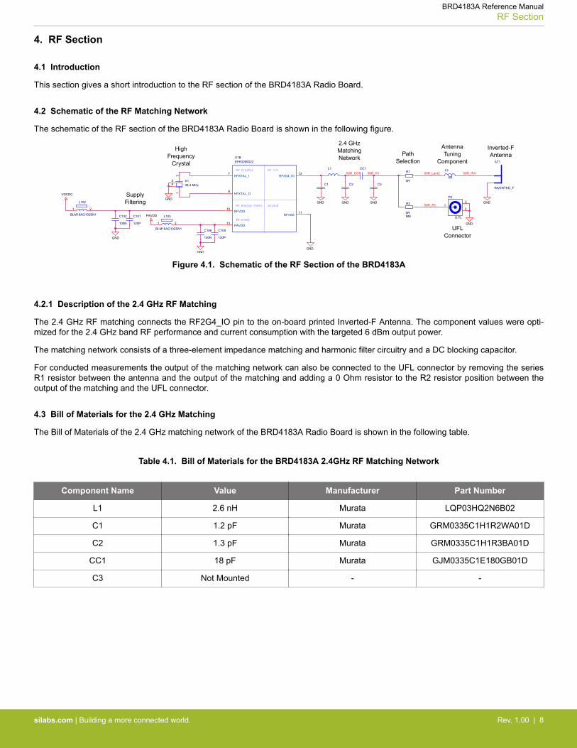
4.2 Schematic of the RF Matching Network
The schematic of the RF section of the BRD4183A Radio Board is shown in the following figure.
PAVDD
VDCDC
GND
GNDGND GND
GND
GND
GND
GND
GND
C2
L102
BLM18AG102SN1
1 2
CC1
P2
U.FL
3
21
X138.4 MHz
31
24 C1
L103
BLM18AG102SN1
1 2
C3
Ground
RF I/ORF Crystal
RF Analog Power
PA Power
U1BEFR32MG22
RF2G4_IO12
RFVDD10
HFXTAL_I7
HFXTAL_O8
PAVDD13
RFVSS11
C105
120P
AT1
INVERTED_F
C106
100N
C102
100N
R1
0R
L3
0R
C101
120P
L1
R2
0RNM
50R_P2
50R_IFA50R_Lant250R_CC1 50R_R1
2.4 GHzMatchingNetwork
PathSelection
Inverted-FAntenna
SupplyFiltering
UFLConnector
AntennaTuning
Component
HighFrequency
Crystal
Figure 4.1. Schematic of the RF Section of the BRD4183A
4.2.1 Description of the 2.4 GHz RF Matching
The 2.4 GHz RF matching connects the RF2G4_IO pin to the on-board printed Inverted-F Antenna. The component values were opti-mized for the 2.4 GHz band RF performance and current consumption with the targeted 6 dBm output power.
The matching network consists of a three-element impedance matching and harmonic filter circuitry and a DC blocking capacitor.
For conducted measurements the output of the matching network can also be connected to the UFL connector by removing the seriesR1 resistor between the antenna and the output of the matching and adding a 0 Ohm resistor to the R2 resistor position between theoutput of the matching and the UFL connector.
4.3 Bill of Materials for the 2.4 GHz Matching
The Bill of Materials of the 2.4 GHz matching network of the BRD4183A Radio Board is shown in the following table.
Table 4.1. Bill of Materials for the BRD4183A 2.4GHz RF Matching Network
Component Name Value Manufacturer Part Number
L1 2.6 nH Murata LQP03HQ2N6B02
C1 1.2 pF Murata GRM0335C1H1R2WA01D
C2 1.3 pF Murata GRM0335C1H1R3BA01D
CC1 18 pF Murata GJM0335C1E180GB01D
C3 Not Mounted - -
BRD4183A Reference ManualRF Section
silabs.com | Building a more connected world. Rev. 1.00 | 8

4.4 Inverted-F Antenna
The BRD4183A Radio Board includes an on-board printed inverted-F antenna, tuned for the 2.4 GHz band. Due to the design restric-tions of the Radio Board, the input of the antenna and the output of the matching network can't be placed directly next to each other.Therefore, a 50 Ohm transmission line was necessary to connect them.
The resulting impedance, that is presented to the output of the matching network, is shown in the following figure. During the measure-ment, the BRD4183A Radio Board was attached to a Wireless Starter Kit Mainboard.
As it can be observed, the antenna impedace (blue curve) is close to 50 Ohm in the entire 2.4 GHz band, the reflection (red curve) isunder -10 dB.
Figure 4.2. Impedance and Reflection of the Inverted-F Antenna of the BRD4183A Board Measured from the Matching Output
BRD4183A Reference ManualRF Section
silabs.com | Building a more connected world. Rev. 1.00 | 9
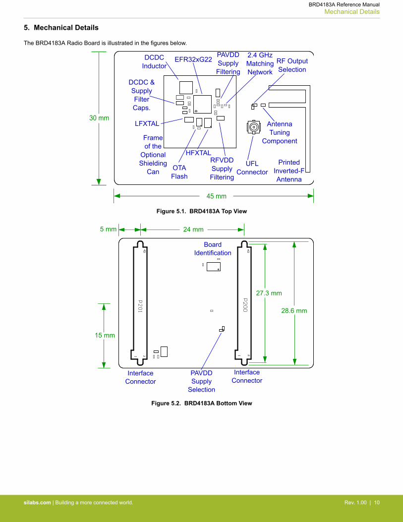
5. Mechanical Details
The BRD4183A Radio Board is illustrated in the figures below.
45 mm
30 mm
PrintedInverted-FAntenna
2.4 GHzMatchingNetwork
Frameof the
OptionalShielding
Can
EFR32xG22
LFXTAL
HFXTAL
PAVDDSupplyFiltering
RFVDDSupplyFiltering
RF OutputSelection
DCDCInductor
AntennaTuning
Component
DCDC &SupplyFilterCaps.
OTAFlash
UFLConnector
Figure 5.1. BRD4183A Top View
24 mm
15 mm
27.3 mm
28.6 mm
5 mm
InterfaceConnector
InterfaceConnector
BoardIdentification
PAVDDSupply
Selection
Figure 5.2. BRD4183A Bottom View
BRD4183A Reference ManualMechanical Details
silabs.com | Building a more connected world. Rev. 1.00 | 10

6. EMC Compliance
6.1 Introduction
Compliance of the fundamental and harmonic levels of the BRD4183A Radio Board is tested against the following standards:
• 2.4 GHz:• ETSI EN 300-328• FCC 15.247
6.2 EMC Regulations for 2.4 GHz
6.2.1 ETSI EN 300-328 Emission Limits for the 2400-2483.5 MHz Band
Based on ETSI EN 300-328, the allowed maximum fundamental power for the 2400-2483.5 MHz band is 20 dBm EIRP. For the unwan-ted emissions in the 1 GHz to 12.75 GHz domain, the specific limit is -30 dBm EIRP.
6.2.2 FCC15.247 Emission Limits for the 2400-2483.5 MHz Band
FCC 15.247 allows conducted output power up to 1 Watt (30 dBm) in the 2400-2483.5 MHz band. For spurious emissions the limit is-20 dBc based on either conducted or radiated measurement, if the emission is not in a restricted band. The restricted bands are speci-fied in FCC 15.205. In these bands the spurious emission levels must meet the levels set out in FCC 15.209. In the range from960 MHz to the frequency of the 5th harmonic, it is defined as 0.5 mV/m at 3 m distance which equals to -41.2 dBm in EIRP.
If operating in the 2400-2483.5 MHz band, the 2nd, 3rd, and 5th harmonics can fall into restricted bands. As a result, for those harmon-ics the -41.2 dBm limit should be applied. For the 4th harmonic the -20 dBc limit should be applied.
6.2.3 Applied Emission Limits for the 2.4 GHz Band
The above ETSI limits are applied both for conducted and radiated measurements.
The FCC restricted band limits are radiated limits only. In addition, Silicon Labs applies the same restrictions to the conducted spec-trum. By doing so, compliance with the radiated limits can be estimated based on the conducted measurement, by assuming the use ofan antenna with 0 dB gain at the fundamental and the harmonic frequencies.
The overall applied limits are shown in the table below. For the harmonics, that fall into the FCC restricted bands, the FCC 15.209 limitis applied, the ETSI EN 300-328 limit is applied for the rest.
Table 6.1. Applied Limits for Spurious Emissions for the 2.4 GHz Band
Harmonic Frequency Limit
2nd 4800~4967 MHz -41.2 dBm
3rd 7200~7450.5 MHz -41.2 dBm
4th 9600~9934 MHz -30.0 dBm
5th 12000~12417.5 MHz -41.2 dBm
BRD4183A Reference ManualEMC Compliance
silabs.com | Building a more connected world. Rev. 1.00 | 11
7. RF Performance
7.1 Conducted Power Measurements
During measurements, the BRD4183A Radio Board was attached to a Wireless Starter Kit Mainboard which was supplied by USB. Thevoltage supply for the Radio Board was 3.3 V.
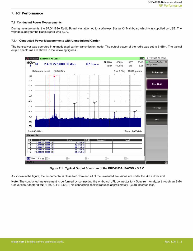
7.1.1 Conducted Power Measurements with Unmodulated Carrier
The transceiver was operated in unmodulated carrier transmission mode. The output power of the radio was set to 6 dBm. The typicaloutput spectrums are shown in the following figures.
Figure 7.1. Typical Output Spectrum of the BRD4183A; PAVDD = 3.3 V
As shown in the figure, the fundamental is close to 6 dBm and all of the unwanted emissions are under the -41.2 dBm limit.
Note: The conducted measurement is performed by connecting the on-board UFL connector to a Spectrum Analyzer through an SMAConversion Adapter (P/N: HRMJ-U.FLP(40)). This connection itself introduces approximately 0.3 dB insertion loss.
BRD4183A Reference ManualRF Performance
silabs.com | Building a more connected world. Rev. 1.00 | 12
7.1.2 Conducted Power Measurements with Modulated Carrier
Depending on the applied modulation scheme, and the Spectrum Analyzer settings specified by the relevant EMC regulations, themeasured power levels are usually lower compared to the results with unmodulated carrier. These differences will be measured andused as relaxation factors on the results of the radiated measurement performed with unmodulated carrier. This way, the radiated com-pliance with modulated transmission can be evaluated.
In this case, both the ETSI EN 300-328 and the FCC 15.247 regulations define the following Spectrum Analyzer settings for measuringthe unwanted emissions above 1 GHz:• Detector: Average• RBW: 1 MHz
The table below shows the measured differences in case of the supported modulation schemes.
Table 7.1. Measured Relaxation Factors for the Supported Modulation Schemes
Applied Modulation(Packet Length:
255 bytes)
BLE Coded PHY:125 Kb/s (PRBS9) [dB]
BLE Coded PHY:500 Kb/s (PRBS9) [dB]
BLE 1M PHY: 1 Mb/s(PRBS9) [dB]
BLE 2M PHY: 2 Mb/s(PRBS9) [dB]
2nd harmonic -2.7 -3.1 -3.3 -9.1
3rd harmonic -4.8 -5.2 -5.2 -10.7
4th harmonic -5.5 -6.5 -6.7 -11.9
5th harmonic -6.3 -6.5 -6.7 -11.4
As it can be observed, the BLE 125 Kb/s coded modulation scheme has the lowest relaxation factors. These values will be used as theworst case relaxarion factors for the radiated measurements.
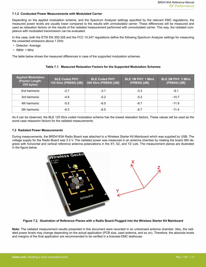
7.2 Radiated Power Measurements
During measurements, the BRD4183A Radio Board was attached to a Wireless Starter Kit Mainboard which was supplied by USB. Thevoltage supply for the Radio Board was 3.3 V. The radiated power was measured in an antenna chamber by rotating the board 360 de-grees with horizontal and vertical reference antenna polarizations in the XY, XZ, and YZ cuts. The measurement planes are illustratedin the figure below.
XZ
Y
Figure 7.2. Illustration of Reference Planes with a Radio Board Plugged into the Wireless Starter Kit Mainboard
Note: The radiated measurement results presented in this document were recorded in an unlicensed antenna chamber. Also, the radi-ated power levels may change depending on the actual application (PCB size, used antenna, and so on). Therefore, the absolute levelsand margins of the final application are recommended to be verified in a licensed EMC testhouse.
BRD4183A Reference ManualRF Performance
silabs.com | Building a more connected world. Rev. 1.00 | 13

7.2.1 Maximum Radiated Power Measurements
For the transmitter antenna, the on-board printed inverted-F antenna of the BRD4183A Radio Board was used (the R1 resistor wasmounted). The supply for the RF section (RFVDD) and the 2.4 GHz power amplifier (PAVDD) was 1.8 V provided by the on-chip DC-DCconverter; for details, see the schematic of the BRD4183A. The transceiver was operated in unmodulated carrier transmission mode.The output power of the radio was set to 6 dBm based on the conducted measurement.
The results are shown in the tables below. The correction factors are applied based on the BLE 125 Kb/s coded modulation, showed insection 7.1.2 Conducted Power Measurements with Modulated Carrier. For the rest of the supported modulation schemes the correc-tion factors are larger, thus the related calculated margins would be higher compared to the ones shown in the table below. Thus thebelow margins can be considered as worst case margins.
Table 7.2. Maximums of the Measured Radiated Powers in EIRP [dBm] and the Calculated Modulated Margins in [dB] with theWireless Starter Kit Mainboard; PAVDD = 3.3 V
Frequency(2450 MHz)
Measured Un-modulated EIRP
[dBm]Orientation
BLE 125 Kb/s Coded ModulationLimit in EIRP
[dBm]Correction Fac-tor [dB]
CalculatedModulated EIRP
[dBm]
Modulated Mar-gin [dB]
Fund 9.1 YZ/V NA (0 is used) 9.1 20.9 30.0
2nd -57.1 YZ/H -2.7 -58.9 18.6 -41.2
3rd -40.7 YZ/H -4.8 -45.5 4.3 -41.2
4th <-50* -/- -5.5 - >20 -30.0
5th -39.9 YZ/H -6.3 -46.2 5.0 -41.2
* Signal level is below the Spectrum Analyzer noise floor.
As it it is shown in the table, with 6 dBm output power, the radiated power of the fundamental is higher than 6 dBm due to the highantenna gain. The 3rd and 5th harmonics are above the limit in with the Wireless Starter Kit Mainboard in case of the unmodulatedcarrier transmission. But with the relaxation of the supported modulation schemes, the margin is at least 4.3 dB and 5.0 dB, respective-ly.
7.2.2 Antenna Pattern Measurements
The measured normalized antenna patterns are shown in the following figures.
0°
45°
90°
135°
180°
225°
270°
315°
-35
-30
-25
-20
-15
-10
-5
0
Normalized Radiation Pattern [dB], BRD4183A with WSTK, XY cut
Horizontal
Vertical
0°
45°
90°
135°
180°
225°
270°
315°
-35
-30
-25
-20
-15
-10
-5
0
Normalized Radiation Pattern [dB], BRD4183A with WSTK, XZ cut
Horizontal
Vertical
0°
45°
90°
135°
180°
225°
270°
315°
-35
-30
-25
-20
-15
-10
-5
0
Normalized Radiation Pattern [dB], BRD4183A with WSTK, YZ cut
Horizontal
Vertical0°= X axis 0°= Z axis 0°= Z axis
Figure 7.3. Normalized Antenna Pattern of the BRD4183A with the Wireless Starter Kit Mainboard
BRD4183A Reference ManualRF Performance
silabs.com | Building a more connected world. Rev. 1.00 | 14

8. EMC Compliance Recommendations
8.1 Recommendations for 2.4 GHz ETSI EN 300-328 Compliance
As shown in section 7.2.1 Maximum Radiated Power Measurements, the power of the fundamental of the BRD4183A Wireless GeckoRadio Board with 6 dBm output is compliant with the 20 dBm limit of the ETSI EN 300-328 regulation. With the supported modulationschemes, the harmonics are also compliant with the relevant limits. Although the BRD4183A Radio Board has an option for mounting ashielding can, it is not required for the compliance.
8.2 Recommendations for 2.4 GHz FCC 15.247 Compliance
As shown in section 7.2.1 Maximum Radiated Power Measurements, the power of the fundamental of the BRD4183A Wireless GeckoRadio Board with 6 dBm output is compliant with the 30 dBm limit of the FCC 15.247 regulation. With the supported modulationschemes, the harmonics are also compliant with the relevant limits. Although the BRD4183A Radio Board has an option for mounting ashielding can, it is not required for the compliance.
BRD4183A Reference ManualEMC Compliance Recommendations
silabs.com | Building a more connected world. Rev. 1.00 | 15

9. Board Revision History
The board revision can be found laser engraved in the Board Info field on the bottom side of the PCB, as outlined in the figure below.The revision printed on the silkscreen marks the PCB revision.
BoardRevision
PCBRevision
BRD4183A Rev. A00
PCB4
183A
Rev
. A00
123456789
Figure 9.1. Revision Info
Table 9.1. BRD4183A Radio Board Revision History
Board Revision Description
A00 Initial production release.
BRD4183A Reference ManualBoard Revision History
silabs.com | Building a more connected world. Rev. 1.00 | 16

10. Errata
There are no known errata at present.
BRD4183A Reference ManualErrata
silabs.com | Building a more connected world. Rev. 1.00 | 17

11. Document Revision History
Revision 1.0
March, 2020
• Initial document revision.
BRD4183A Reference ManualDocument Revision History
silabs.com | Building a more connected world. Rev. 1.00 | 18

Simplicity StudioOne-click access to MCU and wireless tools, documentation, software, source code libraries & more. Available for Windows, Mac and Linux!
IoT Portfoliowww.silabs.com/IoT
SW/HWwww.silabs.com/simplicity
Qualitywww.silabs.com/quality
Support and Communitycommunity.silabs.com
http://www.silabs.com
Silicon Laboratories Inc.400 West Cesar ChavezAustin, TX 78701USA
DisclaimerSilicon Labs intends to provide customers with the latest, accurate, and in-depth documentation of all peripherals and modules available for system and software implementers using or intending to use the Silicon Labs products. Characterization data, available modules and peripherals, memory sizes and memory addresses refer to each specific device, and "Typical" parameters provided can and do vary in different applications. Application examples described herein are for illustrative purposes only. Silicon Labs reserves the right to make changes without further notice to the product information, specifications, and descriptions herein, and does not give warranties as to the accuracy or completeness of the included information. Without prior notification, Silicon Labs may update product firmware during the manufacturing process for security or reliability reasons. Such changes will not alter the specifications or the performance of the product. Silicon Labs shall have no liability for the consequences of use of the information supplied in this document. This document does not imply or expressly grant any license to design or fabricate any integrated circuits. The products are not designed or authorized to be used within any FDA Class III devices, applications for which FDA premarket approval is required or Life Support Systems without the specific written consent of Silicon Labs. A "Life Support System" is any product or system intended to support or sustain life and/or health, which, if it fails, can be reasonably expected to result in significant personal injury or death. Silicon Labs products are not designed or authorized for military applications. Silicon Labs products shall under no circumstances be used in weapons of mass destruction including (but not limited to) nuclear, biological or chemical weapons, or missiles capable of delivering such weapons. Silicon Labs disclaims all express and implied warranties and shall not be responsible or liable for any injuries or damages related to use of a Silicon Labs product in such unauthorized applications.
Trademark InformationSilicon Laboratories Inc.® , Silicon Laboratories®, Silicon Labs®, SiLabs® and the Silicon Labs logo®, Bluegiga®, Bluegiga Logo®, ClockBuilder®, CMEMS®, DSPLL®, EFM®, EFM32®, EFR, Ember®, Energy Micro, Energy Micro logo and combinations thereof, "the world’s most energy friendly microcontrollers", Ember®, EZLink®, EZRadio®, EZRadioPRO®, Gecko®, Gecko OS, Gecko OS Studio, ISOmodem®, Precision32®, ProSLIC®, Simplicity Studio®, SiPHY®, Telegesis, the Telegesis Logo®, USBXpress® , Zentri, the Zentri logo and Zentri DMS, Z-Wave®, and others are trademarks or registered trademarks of Silicon Labs. ARM, CORTEX, Cortex-M3 and THUMB are trademarks or registered trademarks of ARM Holdings. Keil is a registered trademark of ARM Limited. Wi-Fi is a registered trademark of the Wi-Fi Alliance. All other products or brand names mentioned herein are trademarks of their respective holders.