BRB Systems U.S.A. - Voice Release Clay Target Systems
24
1 BRB Systems USA Co. Instruction Manual – WS-101 Wireless Skeet Voice Release System IMPORTANT: Read and understand this manual before assembling, installing or using this system. Improper use of this system can cause serious injury. Table of Contents (1) Safety Information………………………………... (2) Assembly…………………………………………….. (3) Installation…………………………………………... (4) User Options, Set Up & Descriptions…………. (4.1) WS-TRX-101 Button Controller……….. (4.2)RX-101 Receiver…………………………... (4.3)WS-VB-101 Voice Box…………………… (5) Operation……………………………………………. (5.1) RX-101 Receiver………………………….. (5.2) WS-VB-101 Voice Box…………………... (5.3)WS-TRX-101 Button Controller………... (6) Charging……………………………………………... (7) Maintenance………………………………………… (8) Warranty…………………………………………….. 2 3 5 6 7 7 8 14 14 15 17 21 22 23 Page
Transcript of BRB Systems U.S.A. - Voice Release Clay Target Systems

1
BRB Systems USA Co.
Instruction Manual – WS-101
Wireless Skeet Voice Release System
IMPORTANT: Read and understand this manual before assembling, installing or
using this system. Improper use of this system can cause serious injury.
Table of Contents
(1) Safety Information………………………………...
(2) Assembly……………………………………………..
(3) Installation…………………………………………...
(4) User Options, Set Up & Descriptions………….
(4.1) WS-TRX-101 Button Controller………..
(4.2)RX-101 Receiver…………………………...
(4.3)WS-VB-101 Voice Box……………………
(5) Operation…………………………………………….
(5.1) RX-101 Receiver…………………………..
(5.2) WS-VB-101 Voice Box…………………...
(5.3)WS-TRX-101 Button Controller………...
(6) Charging……………………………………………...
(7) Maintenance…………………………………………
(8) Warranty……………………………………………..
2
3
5
6
7
7
8
14
14
15
17
21
22
23
Page

2
(1) Safety Information
Make certain that any person assembling or installing this system has read and
fully understood this Instruction Manual. It is your guide to safe and proper
operation of this system.
WS-TRX-101 Button Controllers are 6V dc, powered by 4 AA batteries.
AA batteries are small, but powerful and must be treated with respect.
Never short the ends of the battery together. Never burn the battery, even
when you think it is fully discharged.
RX-101 Receivers sold as 12V, are to be powered with 12V dc power sources
only.
The 12V dc power sources that may be used with the receivers are; 12V lead
acid batteries, 12V regulated ac to dc power supplies and 12V dc power
directly from the trap.
12V lead acid batteries (such as car type batteries) contain acid and so
extreme care must be taken when handing them.
12V car batteries are capable of supplying large amounts of current and care
must be taken not to connect the + (red) and – (black) terminals together.
RX-101 Receivers sold as 120V, are to be powered with 120V ac power
sources only. Do not defeat the safety purpose of the polarized, or
grounding type, plug fitted to this apparatus. If the provided plug does not
fit into your outlet consult a qualified electrician. Exterior 120V outlets
should be GFCI protected for your safety. If the outlet is not GFCI protected
then contact a qualified electrician for rectification.
Protect any power cord from being walked on, pinched or damaged in any way.
Disconnect this apparatus from its power source during lightning storms.
CAUTION:
This system is powered by electricity. To reduce the risk of electric shock, do
not tamper with any part of the apparatus. There are no user serviceable
parts of this equipment. Refer servicing to BRB Systems USA Co.
3
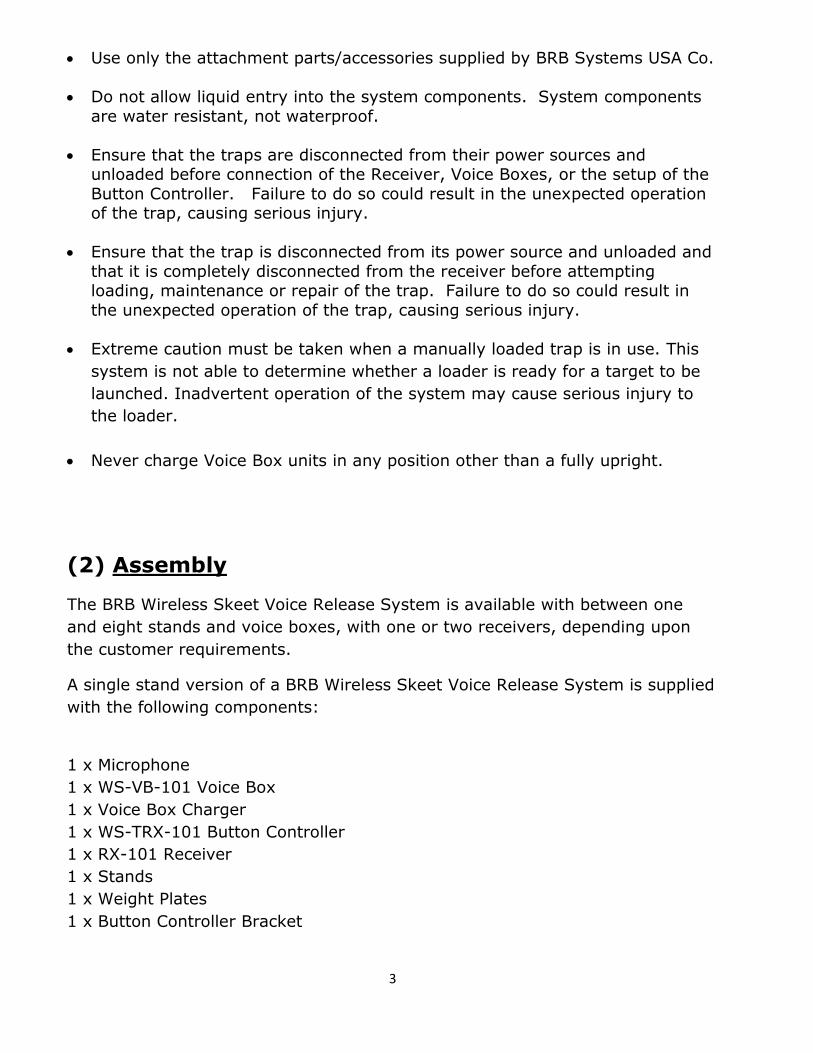
Use only the attachment parts/accessories supplied by BRB Systems USA Co.
Do not allow liquid entry into the system components. System components
are water resistant, not waterproof.
Ensure that the traps are disconnected from their power sources and unloaded before connection of the Receiver, Voice Boxes, or the setup of the
Button Controller. Failure to do so could result in the unexpected operation of the trap, causing serious injury.
Ensure that the trap is disconnected from its power source and unloaded and
that it is completely disconnected from the receiver before attempting loading, maintenance or repair of the trap. Failure to do so could result in
the unexpected operation of the trap, causing serious injury.
Extreme caution must be taken when a manually loaded trap is in use. This
system is not able to determine whether a loader is ready for a target to be
launched. Inadvertent operation of the system may cause serious injury to
the loader.
Never charge Voice Box units in any position other than a fully upright.
(2) Assembly
The BRB Wireless Skeet Voice Release System is available with between one
and eight stands and voice boxes, with one or two receivers, depending upon
the customer requirements.
A single stand version of a BRB Wireless Skeet Voice Release System is supplied
with the following components:
1 x Microphone
1 x WS-VB-101 Voice Box
1 x Voice Box Charger
1 x WS-TRX-101 Button Controller
1 x RX-101 Receiver
1 x Stands
1 x Weight Plates
1 x Button Controller Bracket

4
Stands
The stand is made to be mounted to the weight plate. Bolt the stand to the
weight plate as in the diagram below.
Microphones
The microphone bolts to the top of the stand with the bolt, washers and wing
nut supplied.
The microphone should be bolted to the stand so that the foot pedal faces away
from the shooter. Set the microphone to an angle that directs the opening
toward a shooters head at approximately 3ft away.
If the stand is to be used by a single shooter for practice, then replace the
microphone mounting bolt with the supplied button controller bracket.
WS-VB-101 Voice Box
The voice box is mounted to its stand mounting brackets.
Remove the wing nuts, lock washers and flat washers from the voice box studs.
Slide the studs through the four holes in the stand mounting brackets. Refit the
flat washers, lock washers and wing nuts. Screw hand tight.
Screw the 2 pin plug into the microphone socket. Zip tie the cable to the shaft
of the stand in a way that makes a large loose cable bend at the microphone, so
that if the microphone is turned downwards it does not pull the plug connection.
5
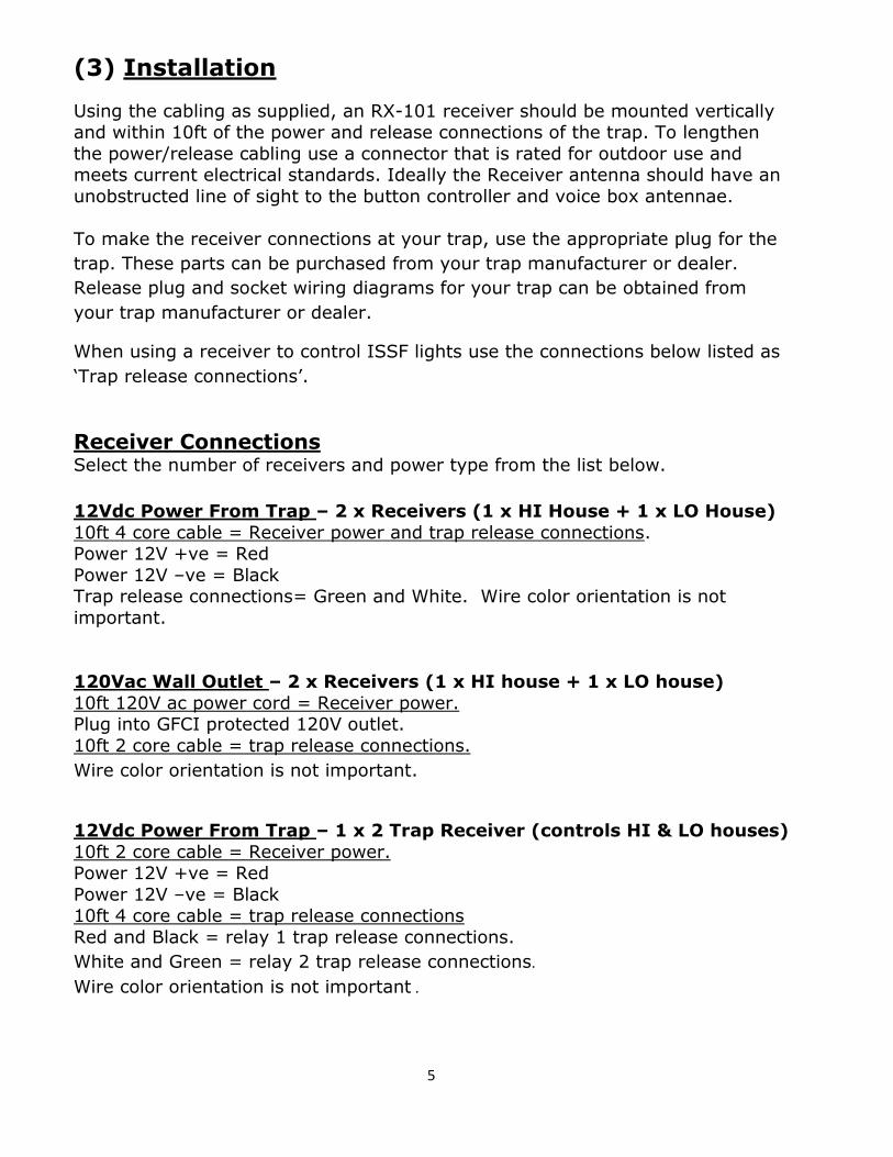
(3) Installation
Using the cabling as supplied, an RX-101 receiver should be mounted vertically and within 10ft of the power and release connections of the trap. To lengthen
the power/release cabling use a connector that is rated for outdoor use and meets current electrical standards. Ideally the Receiver antenna should have an
unobstructed line of sight to the button controller and voice box antennae.
To make the receiver connections at your trap, use the appropriate plug for the
trap. These parts can be purchased from your trap manufacturer or dealer.
Release plug and socket wiring diagrams for your trap can be obtained from
your trap manufacturer or dealer.
When using a receiver to control ISSF lights use the connections below listed as
‘Trap release connections’.
Receiver Connections Select the number of receivers and power type from the list below.
12Vdc Power From Trap – 2 x Receivers (1 x HI House + 1 x LO House)
10ft 4 core cable = Receiver power and trap release connections. Power 12V +ve = Red
Power 12V –ve = Black Trap release connections= Green and White. Wire color orientation is not
important.
120Vac Wall Outlet – 2 x Receivers (1 x HI house + 1 x LO house)
10ft 120V ac power cord = Receiver power. Plug into GFCI protected 120V outlet.
10ft 2 core cable = trap release connections.
Wire color orientation is not important.
12Vdc Power From Trap – 1 x 2 Trap Receiver (controls HI & LO houses)
10ft 2 core cable = Receiver power. Power 12V +ve = Red
Power 12V –ve = Black 10ft 4 core cable = trap release connections
Red and Black = relay 1 trap release connections.
White and Green = relay 2 trap release connections.
Wire color orientation is not important .
6
120Vac Wall Outlet – 1 x 2 Trap Receiver (controls HI & LO houses)
10ft 120V ac power cord = Receiver power. Plug into GFCI protected 120V outlet.
10ft 4 core cable = trap release connections.
Red and Black = relay 1 trap release connections.
White and Green = relay 2 trap release connections.
Wire color orientation is not important .
(4) User Options & Set Up
This equipment has been designed for ultimate versatility, which is
achieved by offering a large number of user options. Each user option
needs to be set. Unless specified otherwise when ordered, each piece
of this equipment will be preset to factory settings before shipping. For
many customers no changes will be necessary. Should you need to
make any changes from the factory settings a comprehensive
description of how to do so follows.
FACTORY SETTINGS
Radio frequency (CHN) = Club unique
Radio encoding (CODE) = Club unique
Voice Release LED mode (LISTEN VOICE) = On
Rounds LED mode (LISTEN ROUNDS) = On
Delay before target release (DELAY) = None
Must use with counter (CTR) = No
Discipline used in Rounds (SRT) = NSSA Skeet
Skeet Rounds advance type (SRB) = Button advance
Receiver relay closed time (REL1 CLOSE & REL2 CLOSE) = 0.25 seconds
Equipment use type (RX FUNC) = Wireless Skeet Voice Release System
Inactivity power down (SLEEP) = 10 minutes
Unwanted noise rejection (NOISE REJECT) = Minimum
Microphone sensitivity (MIC) = Center of range
If you require settings any different than the factory settings, these can be
changed by following the instructions using the tables and descriptions that
follow.

7
(4.1) WS-TRX-101 Button Controller Set Up
Button Controller Dipswitch Settings Switch numbers are printed on the body of the dipswitch.
UPPER
1 2 3 4 5 6 7 8
CODE CHN CHN CHN CHN CHN CHN CHN CHN sets receiver ID frequency - TRX, RX &VB must all match
MIDDLE
1 2 3 4 5 6 7 8
CODE CODE CODE CODE LISTEN VOICE
LISTEN ROUND
DELAY DELAY CODE sets receiver ID encoding – TRX, RX &VB must all match LISTEN sets real time TRX target status LED’s ON or OFF DELAY sets the target release delay time
LOWER
1 2 3 4 5 6 7 8
CTR CTR CTR CTR SRB OFF SRT SRT CTR switches same as Upper switches 1,2,3 & 4 = Use without counter Any CTR switch different from Upper 1,2,3 & 4 = Only with counter SRB sets auto. or semi-auto. station advance - for use in Rounds SRT sets the Skeet discipline - for use in Rounds
(4.2) RX-101 Receiver Set Up
Receiver Dipswitch Settings
Switch numbers are printed on the body of the dipswitch.
SW3
1 2 3 4 5 6 7 8
CODE CHN CHN CHN CHN CHN CHN CHN CHN sets receiver ID frequency - TRX, RX &VB must all match
SW2
1 2 3 4 5 6 7 8
CODE CODE CODE CODE REL1 FUNC
REL1 FUNC
REL2 FUNC
REL2 FUNC
CODE sets receiver ID encoding – TRX, RX &VB must all match REL FUNC sets each relay for HI-house, LO-house or ISSF lights
SW1
1 2 3 4 5 6 7 8
REL1 CLOSE
REL2 CLOSE
OFF OFF OFF OFF RX FUNC
RX FUNC
REL1 CLOSE and REL2 CLOSE set relay contact closed times RX FUNC sets which equipment model a receiver is used with – Wireless Trap, Wireless Skeet or TX-101

8
(4.3) WT-VB-101 Voice Box Set Up
Voice Box Dipswitch Settings
Power off the Voice Box to change dipswitch settings, or the changes will not be
recognized by the equipment.
SW1
1 2 3 4 5 6 7 8
CODE CHN CHN CHN CHN CHN CHN CHN CHN sets receiver ID frequency - TRX, RX &VB must all match
SW2
1 2 3 4 5 6 7 8
CODE CODE CODE CODE MIC MIC MIC MIC CODE sets receiver ID encoding – TRX, RX &VB must all match MIC sets the microphone sensitivity
SW3
1 2 3 4 5 6 7 8
SLEEP SLEEP SLEEP NOISE REJECT
NOISE REJECT
OFF OFF OFF SLEEP sets the time until power down after inactivity NOISE REJECT sets the level of noise rejection
CHN Signal Frequency – Set in Button Controller, Receiver & Voice Box
The seven CHN dipswitches (switches 2-8 on the Upper dipswitch) are the
primary method of system identification. These dipswitches must match on the
Receiver, Button Controller and Voice Box for the system to operate. They set
the frequency of the transmission signal and give 128 possible frequency
variations. Using these settings for identification eliminates cross calls between
adjacent fields because each field can have a different working frequency.
CODE Signal Encoding – Set in Button Controller, Receiver & Voice Box
The five CODE dipswitches (switch 1 on the 1st dipswitch & switches 1, 2, 3 & 4
of the 2nd dipswitch) are the secondary method of system identification. These
dipswitches must match on the Receiver, Button Controller and Voice Box for
the system to operate. They set the signal encoding, do not affect the
transmission frequency and expand the possible number of individual system
identities to 4096.

9
LISTEN LED Operation – Set in Button Controller
The two LISTEN dipswitches (5 & 6 on the Middle dipswitch) switch on or off the
two types of Listen mode.
LISTEN VOICE – Switches on Listen in Voice Target Release
LISTEN ROUNDS – Switches on Listen in Rounds Target Release
With Listen on, the Button Controller LED’s will display the next target to be
released and the target after next to be released, in real time. As a target is
released the LED’s will update to always show the next 2 targets.
With Listen off, when the target selections are made, the Button Controller
LED’s will light to show the next two targets to be released for a few seconds
only before extinguishing.
Listen mode requires the Button Controller to eavesdrop on the system radio traffic, which uses a significant amount of Button Controller battery power.
Out of LISTEN mode the Button Controller battery life is over 1,000,000 button presses.
In Listen mode the battery life is reduced to approx. 50,000 button presses in Voice Release, or 50 hours in Rounds.
The possible Listen dipswitch settings are:
MIDDLE
5 Button Controller Voice Release LED Mode OFF Button Controller Listen Voice Release mode OFF
ON Button Controller Listen mode ON
MIDDLE
6 Button Controller Rounds LED Mode OFF Button Controller Listen Rounds mode OFF
ON Button Controller Listen Rounds mode ON

10
DELAY Target Release Delay Time – Set in Button Controller
The two DELAY dipswitches (7 & 8 on the Middle dipswitch) are used to set any
required delay between the shooters call and the target release.
The possible Delay dipswitch settings are:
MIDDLE
7 8 Delay Type
OFF OFF No delay
OFF ON 1/6th
second delay
ON OFF Random 0-1.4 seconds delay
ON ON Random 0-3 seconds delay
CTR Counter Use Dipswitches – Set in Button Controller
The four CTR dipswitches (1, 2, 3 & 4 on the Lower dipswitch) allow the club to
set the equipment for use with or without a counter.
To use the equipment without a counter, switches 1, 2, 3 & 4 of the lower
dipswitch must match those of switches 1, 2, 3 & 4 of the upper dipswitch. If
there is any difference between these, the equipment will only operate with a
counter. This feature allows the club to easily alternate between counter and
non-counter use by only changing dipswitches in the Button Controller.
SRT Skeet Rounds Type – Set in Button Controller
The two SRT dipswitches (7 & 8 on the Lower dipswitches) set the Skeet
discipline when the equipment is used in Rounds mode.
Rounds mode allows the equipment to voice release an entire sequence of
targets in a round, without the shooter needing to button select the targets.
Having Rounds mode set up does not force the user to use Rounds. Single
targets, Doubles, HI-LO or LO-HI sequences can also be selected.
The possible SRT dipswitch settings are:
LOWER
7 8 Skeet Rounds Type
OFF OFF NONE – Do not allow Skeet Rounds
OFF ON ISSF – International Skeet
ON OFF NSSA – American Skeet
ON ON CPSA – English Skeet

11
SRB Skeet Rounds Button – Set in Button Controller
The SRB dipswitch (5 on the Lower dipswitch) sets the type of advancement
between stations when using Rounds mode.
Voice Release Rounds sequencing has two choices of advancement between
stations:
The two choices are:
SRB off – For single shooter use.
No button press is necessary to advance station. Set this way the
equipment automatically advances to the next station target sequence
upon completion of the last and opens the microphone.
SRB on – For single or multiple shooter use.
A button press is needed to advance station. Set this way the equipment
advances to the next station target sequence and opens the microphone
when the advance button is pressed.
The possible SRB dipswitch settings are:
LOWER
5 Skeet Rounds Button OFF Skeet Round Button OFF – Automatic station advancement
ON Skeet Round Button ON – Button press station advancement
REL1 FUNC & REL2 FUNC Relay Function – Set in Receiver
The four dipswitches, REL1 FUNC (5 & 6 on SW2) & REL2 FUNC (7 & 8 on SW2)
are used to set which trap (or light – ISSF) each of the two receiver relays
operates.
A standard Receiver is supplied with only Relay1 fitted. Relay2 is not fitted
unless requested by the customer when ordering. Unless fitted, no setting is
required for Relay 2.
If using a single relay receiver, or if using only 1 relay of a 2 relay receiver, the
dipswitches for the unused relay must be the same as for the used relay.

12
The possible dipswitch settings for REL1 are:
SW2
5 6 Relay 1 Function
OFF OFF LO-house trap release
ON OFF HI-house trap release
OFF ON LO-house light control
ON ON HI-house light control
The possible dipswitch settings for REL2 are:
SW2
7 8 Relay 2 Function
OFF OFF LO-house trap release
ON OFF HI-house trap release
OFF ON LO-house light control
ON ON HI-house light control
REL1 CLOSE & REL2 CLOSE Relay Closed Time – Set in Receiver
The two dipswitches, REL1 CLOSE (1 on SW1) & REL2 CLOSE (2 on SW1) are
used to set the relay closed times of each of the two receiver relays.
Some traps require a longer receiver relay closed time than others. If set too
short the trap may start to move, but not release a target. If set too long a fast
re-cocking trap may release more than one target for one relay closure.
The possible dipswitch settings for REL1 CLOSE are:
SW1
1 LO-house Relay Closed Times OFF Sets LO-house relay closed time to 0.25 sec.
ON Sets LO-house relay closed time to 0.80 sec.
The possible dipswitch settings for REL2 CLOSE are:
SW1
2 HI-house Relay Closed Times OFF Sets HI-house relay closed time to 0.25 sec.
ON Sets HI-house relay closed time to 0.80 sec.

13
RX FUNC Equipment Use Type – Set in Receiver
The two RX FUNC dipswitches (7 & 8 on SW1) of a receiver, set the model of
BRB equipment the receiver is to be used with.
The possible dipswitch settings are:
SW1
7 8 Equipment Model OFF OFF TX-101 Wireless Button Release
ON OFF Wireless Trap VRS
ON ON Wireless Skeet VRS
SLEEP Inactivity Power Off Time – Set in Voice Box
The three SLEEP dipswitches (1, 2 & 3 on SW3) are used to set the time to
automatically power off a Voice Box, after the last shooters call is heard.
The possible dipswitch settings are:
SW3
1 2 3 Minutes
OFF OFF OFF 10
OFF OFF ON 15
OFF ON OFF 20
OFF ON ON 30
ON OFF OFF 45
ON OFF ON 60
ON ON OFF 90
ON ON ON 120
NOISE REJECT Noise Rejection Dipswitches – Set in Voice Box
The two NOISE REJECT dipswitches (4 & 5 on SW3) are used to set the four
possible noise rejection settings. These settings are used when problems such
as gun closing, echo or gun shots from adjacent fields cause unwanted release
of targets. The recommended noise rejection setting is the lowest that can be
set to remove a noise problem.

14
The possible dipswitch settings are:
SW3
4 5 Noise Rejection Level
OFF OFF Level 1 - Minimum noise rejection
OFF ON Level 2
ON OFF Level 3
ON ON Level 4 - Maximum noise rejection
MIC Microphone Sensitivity Dipswitches – Set in Voice Box
The four MIC dipswitches (5, 6, 7 & 8 on SW2) are used to set the microphone
sensitivity. The sensitivity can be changed up or down using the sixteen
possible settings in the chart below. The range of possible sensitivity
adjustment is high enough that it may be possible to use microphones that were
previously discarded as ‘deaf’ with this equipment.
The possible dipswitch settings are:
SW2
5 6 7 8 Sensitivity
OFF OFF OFF OFF Least sensitive
OFF OFF OFF ON
OFF OFF ON OFF
OFF OFF ON ON
OFF ON OFF OFF
OFF ON OFF ON
OFF ON ON OFF
OFF ON ON ON Standard preset sensitivity
ON OFF OFF OFF
ON OFF OFF ON
ON OFF ON OFF
ON OFF ON ON
ON ON OFF OFF
ON ON OFF ON
ON ON ON OFF
ON ON ON ON Most sensitive

15
(5) Operation
(5.1) RX-101 Receiver Operation
When connected to its power source, the green ‘PWR’ LED will light on the
receiver and will stay lit as long as a good power level is maintained.
If the power supply voltage drops below 10.5V the ‘PWR’ LED will flash
continuously to signify low power.
When the receiver relay closes the corresponding relay LED will light for the
time that the relay is closed. When the relay opens, the LED will flash rapidly
during the trap reload time.
Radio Signal Strength Indication (RSSI)
Optimum location of the receiver can be ensured with the help of the RSSI feature of this equipment. When a message is received from the Button
Controller or Voice Box, the yellow ‘SIG’ LED will flash to show the strength of signal received.
1 flash = weakest signal that can release a target. 5 flashes = strongest signal.
Note – If a strong signal is received, but its message is corrupted (by radio frequency interference etc.) the LED will not flash.
Note - To avoid confusion between signals, if a signal is received within1 second
of completion of the last sequence of flashes its strength will not be displayed on the ‘SIG’ LED.
(5.2) WS-VB-101 Voice Box Operation There are 2 ways to power on a Voice Box, depending upon whether you want
to release a target selection once (non-repeat), or continuously release a target
selection (repeat).
Non-Repeat of a Target or Sequence
When a Voice Box is powered on in Non-Repeat mode, it will release a target or sequence once only. When that target or sequence is released another button
selection must be made to release another target.
To power on a Voice Box, press and release the power button on the top of the unit. When the power button is pressed, an indicator LED will illuminate around
the power on button and an audible ‘Beep’ will sound. The LED will flash to show that the unit is powered on and to show that the microphone is closed.
When the Voice Box has been powered on, the referee can select a target.
When a target has been selected the microphone will open. When the

16
microphone opens, the Voice Box LED will light continuously. A target can now
be released by the shooters call.
Repeat a Target or Sequence – For single or multiple shooters.
When a Voice Box is powered on in Repeat mode, any selected HI, LO, DOUBLE or target sequence will be repeated indefinitely until a new instruction is given.
Put a Voice Box into Repeat if a single shooter wants to repeat targets at a station, or for multiple shooters so that they do not need to button select the
same targets for each shooter.
To power on a Voice Box in Repeat, press and hold the power button for 3 seconds. When the power button is pressed, an indicator LED will illuminate
around the power button and a ‘beep’ will sound. After 3 seconds a second ‘beep’ will sound. The power LED will flash to show that the microphone is
closed.
When the Voice Box has been powered on, the referee can select a target.
When a target has been selected the microphone will open. When the microphone opens the Voice Box LED will fade on and off to show that unit is in
Repeat. A target can now be released by the shooters call.
Charge Level Indication
When powered on, the color of the LED indicates the unit battery charge level.
Green = Full charge – 50% charge. Amber = 50% - 15% charge.
Rapid Flashing Amber = 15% charge. The Voice Box enters Battery
Protection Mode. This starts an automatic 10 minute shutoff timer. After 10 minutes the LED will extinguish, an audible ‘beep’ will sound and the
unit will power off.
If low battery charge level has caused a Voice Box to automatically power off, it can be powered with its charger for as long as is necessary.
Calling For a Target With the microphone installed approximately 3ft from the shooter, the shooter
should be able to call for a target in the same way as if the trap was being released by a person. There is no need to turn and call toward the microphone
or call excessively loudly.
When a call has been detected, the microphone will close and the indicator LED
will change from lit continuously to flashing, to show that it has closed. The LED will flash until the microphone is opened again either by a new target selection
being made, or because Repeat mode is being used, or automatically as part of

17
a sequence. When ready to accept another call the indicator LED will light
continuously.
Powering Off a Voice Box When shooting is finished a Voice Box can be powered off by pressing the power
button. The indicator LED will extinguish and an audible ‘Beep-beep’ will sound.
If any Voice Box in the system does not detect a call for the duration of the set Sleep Inactivity Power Off Time it will automatically power off.
When multiple Voice Boxes are being used, do not power off the Voice box on
the station that has just been completed. Powering-on a new Voice Box will automatically power-off the last and transfer any required system status data to
the new station.
(5.3) WS-TRX-101 Button Controller Operation
The Button Controller sets the type of targets to be released. It has no power
on switch. Simply press any button and the unit will react immediately.
Targets can be released in 3 ways:
Manual Release
Voice Release
Rounds
All 3 target release methods are available to the shooter without changing
dipswitches.
Manual Target Release
HI, LO or DOUBLE targets can be released using the Button Controller without
need for a shooters call. To release a target manually it is not necessary to
have a Voice Box powered on.
The LED beside the red M/VRS button shows if the Button Controller is in Manual
or Voice Release:
LED off = Voice Release
LED on = Manual Release
The default state for a Button Controller is Voice Release mode. To alternate
between Voice Release and Manual Release, press the red M/VRS button for 2.5
seconds until a ‘beep’ is heard and the LED changes state.

18
When the Button Controller has been set to Manual from Voice Release the
M/VRS LED will light to show that the unit is in Manual. Targets can now be
released manually by pressing the HI, LO or DOUBLE buttons.
If no target is selected for 5 minutes the unit will exit Manual and sleep.
Voice Target Release Operation
With the Voice Box powered on and the Button Controller in VRS mode, the
referee can select the targets to be voice released.
The HI, LO and DOUBLE buttons select the target(s) to be released. When the
target buttons are pressed their corresponding LED’s will light and the Voice Box
microphone will open to listen for the shooters call.
Flashing LED = Next target to be released
Continuous LED = Target after next to be released.
Release of SINGLES or DOUBLES When the HI, LO or DOUBLE buttons are pressed the corresponding Button
Controller LED will flash and the Voice Box microphone opens. A target can now be released by the shooters call.
If a target selection is made but not wanted, simply press the red CANCEL
button. Alternatively, making a new selection will override an unwanted
selection. If a new selection is made to override an unwanted single HI or single LO target, a small amount of time must be left to ensure that the new
selection is not seen as the 2nd target of a sequence.
With a Voice Box in Repeat mode, when the target is shot at, the microphone will reopen ready for the next call. The next call will release the same target as
the last. This will repeat until a different target is selected or the red M/VRS
CANCEL button is pressed.
HI/LO & LO/HI SEQUENCES
A HI/LO sequence is selected by pressing the HI button followed by the LO. A LO/HI sequence is selected by pressing the LO button followed by the HI.
When a button sequence is selected the corresponding Button Controller LED’s
will show the target sequence and the Voice Box microphone will open. The first target can now be released by the shooters call. When a call has released the
1st target and a shot is taken, the microphone will automatically reopen for the release call of the 2nd target.
If a target selection is made but not wanted, simply press the red CANCEL
button or make a new selection which will override it.

19
With a Voice Box in Repeat mode, when the HI/LO or LO/HI sequence is completed the microphone will reopen. The next call will release the same
target sequence as the last. This will repeat until a different single target or sequence is selected, or the CANCEL button is pressed.
If no call is detected within 30 seconds of the microphone opening, the target
sequence is cancelled and the unit resets ready for another selection to be
made.
If no gunshot is heard within 5 seconds of a target being released the unit will reset ready for another selection to be made.
ROUNDS Shooting in Rounds allows a partial or entire Skeet round to be shot without
need to select any targets. The system is preprogrammed to know which target sequence to release at each station.
Rounds type choices are: NSSA
CPSA ISSF
No Rounds allowed
Rounds station advancement choices are:
Skeet Rounds Button (SRB)– On Skeet Rounds Button (SRB) – Off
The Rounds type and advancement type are both dipswitch selected during
equipment Set Up.
Entering & Exiting Rounds To enter Rounds mode, power on the Voice Box.
Press the red M/VRS CANCEL and the DOUBLE button. The four green LED’s will revolve in a counter clockwise direction and six ‘Beep’s will sound, to show that
you are entering Rounds. If no Voice Box is powered on, the Button Controller will not react when the
Rounds entry buttons are pressed.
To exit Rounds at any time, press the red M/VRS CANCEL button and the
DOUBLE button. The four green LED’s will alternate between the two halves of an ‘X’ and six ‘Beep’s will sound to show that you are exiting.

20
Shooting in Rounds with SRB On – Semi-automatic Station Advance
For use by a single or multiple shooters.
Using the target sequence for NSSA as an example, starting at Station 1 (HI, LO, DOUBLE), the system operation is as follows:
Entering Rounds the microphone is closed.
Pressing the red M/VRS CANCEL button opens the microphone ready for the shooters call.
The shooter calls for the HI target and the target is released. The HI target is shot at.
The shooter calls for the LO target and the target is released. The LO target is shot at.
The shooter reloads, calls for the DOUBLE and the targets are released. The DOUBLE targets are shot at.
The microphone is closed.
The shooters move to Station 2. Pressing the red M/VRS CANCEL button opens the microphone ready for the
shooters call.
Multiple shooters – Power on the Voice Box in Repeat mode. When a shooter has completed the target sequence the microphone will reopen for the next
shooter. The next call will begin the same target sequence as the last. This will repeat until the red M/VRS CANCEL button is pressed which closes the
microphone and advances the system to the next station. When ready to shoot at the next station, press the M/VRS CANCEL button to re-open the microphone.
At Station 8, when the HI and LO targets have been released and shot at, the
programmed round is complete. The microphone will close, the four green LED’s will alternate between the two halves of an ‘X’ and six ‘Beep’s will sound
to show that you are exiting. Pressing the red M/VRS CANCEL button will have
no effect. If a shooter has not missed any shots through Station 8, the 25th shot can be selected in the same way as any other option shot, by pressing the
HI or LO target of choice.
To begin another round, re-enter Rounds by pressing the red M/VRS Cancel and DOUBLE buttons.
Advancement to the next station can be done at any time, without the previous
station being shot. This allows a shooter to shoot at the stations he wants and miss those he does not. Advancement from station to station is made by
pressing the red M/VRS CANCEL button twice per station. Button press 1 = advance to next station.
Button press 2 = open microphone. Using this method a shooter can start at any station in a round.

21
Shooting in Rounds with SRB Off – Automatic Station Advance
For use by a single shooter only.
Using the target sequence for NSSA as an example, starting at Station 1 (HI, LO, DOUBLE), the system operation is as follows:
Entering Rounds opens the microphone ready for the shooters call.
The shooter calls for the HI target and the target is released. The HI target is shot at.
The shooter calls for the LO target and the target is released. The LO target is shot at.
The shooter reloads, calls for the DOUBLE and the targets are released. The DOUBLE targets are shot at.
The system advances to Station 2 and opens the microphone ready for the shooters call.
Advancement to the next station can be done at any time, without the previous station being shot. This allows a shooter to shoot at the stations he wants and
miss those he does not. Advancement from station to station is made by pressing the red M/VRS CANCEL button once per station.
Button press = advance to next station and open microphone. Using this method a shooter can start at any station in a round.
Option Birds During a round a single HI, single LO or DOUBLE can be released at any time
simply by pressing the desired target button on the Button Controller. Any combination of HI, LO or DOUBLE can be released, in any order, as many times
as required. When no more option buttons are pressed, the round will continue as if no option target(s) was released.
All Rounds Types If no call is detected within 10 minutes of the microphone opening, the target
sequence is cancelled and the unit resets ready for another selection to be made.
If no gunshot is heard within 5 seconds of a target being released the round will
proceed as if a gunshot was heard.
If an option target selection is made but not wanted, make a new selection which will override it. Do not press the red M/VRS CANCEL button because this
will advance the station.
If a low battery voltage is detected in the Button Controller, the red ‘Low Batt’
LED lights for 10 seconds each time a button is pressed.

22
(6) Charging
Only charge a Voice Box with the equipment supplied by BRB Systems
USA Co.
Use of any unauthorized chargers may damage the equipment and
cause a fire.
Use of unauthorized chargers will invalidate your warranty.
Never charge Voice Box units in any position other than fully upright.
Do not store or charge a Voice Box below 0 degrees F. Extremely cold
temperatures will damage the battery and drastically shorten its lifespan.
The simplest way to ensure that a Voice Box unit does not shut off, due to low
battery charge level, is to keep each unit fully charged.
When shooting is finished plug each Voice Box into its charger.
When a charger is connected to a Voice Box the power button LED will show the
battery charge status by lighting amber and green in proportion to the charge
level. As the battery charges, less amber and more green is shown until only
the green LED makes a short flash. When only a short green LED flash shows,
the unit is fully charged.
The Voice Box circuitry acts as both a battery charger and maintainer.
The Voice Box cannot be overcharged. To prolong battery lifespan it is
recommended that each Voice Box be continuously connected to its
charger when not in use. The maximum time between Voice Box charges
should never be longer than three weeks. Any longer period between charges
will reduce the battery capacity and lifespan.
A totally discharged Voice Box should recharge in approximately 7.5 hours.

23
(7) Maintenance
The rugged manufacturing of this Wireless Voice Release System should ensure
many years of trouble free use if it is not abused and given simple maintenance.
Do not allow any component to be immersed in water.
Keep the Voice Boxes fully charged.
Do not leave the equipment outside, in the weather, for indefinite periods
of time. Store in a cool dry place.
Regularly inspect the equipment for wear or damage. If any wear or damage is found seek service from BRB Systems USA Co.
Should difficulty be found with the system operation, do not dismantle any part
of the system. This will void the warranty and may result in an electric shock or
fire.
Refer servicing to BRB Systems USA Co.

24
(8) BRB Systems USA Co. - Limited Warranty
This BRB Systems USA Co. product, supplied in the original packaging to the original purchaser, is warranted against
manufacturing defects in materials and workmanship for a limited warranty period of:
One (1) Year Parts and Labor.
This limited warranty begins on the original date of purchase and is valid only on products purchased and used in the
USA.
This warranty will terminate automatically prior to its stated expiration if the original purchaser sells or transfers the
product to any other party.
BRB Systems USA Co. will repair or replace this product, at our option and at no charge as stipulated herein, with new or
reconditioned parts or products if found to be defective during the limited warranty period specified above.
All replaced parts and products become the property of BRB Systems USA Co. and must be returned to BRB Systems
USA Co.
Replacement parts and products assume the remaining original warranty or ninety (90) days, whichever is longer.
This limited warranty covers defects in materials and workmanship encountered in normal use of this product and shall
not apply to defects or injuries caused by the following, including, but not limited to: damage which occurs in shipment;
delivery and installation; applications and uses for which this product was not intended; product alterations not
authorized by BRB Systems USA Co.; cosmetic damage or exterior finish; accidents; neglect; fire; water damage; vermin
or insect infestation; lightning or other acts of nature; use of products, equipment systems, utilities, services, supplies,
accessories, applications, installations, repairs, external wiring or connectors not supplied or authorized by BRB Systems
USA Co. which damage this product or result in service problems; incorrect electrical line voltage; fluctuations and
surges; customer adjustments and failure to follow operating instructions, cleaning, maintenance and environmental
instructions that are covered and prescribed in the Instruction Manual.
BRB Systems USA Co. does not warrant uninterrupted or error-free operation of the product.
BRB Systems USA Co. shall not be liable for loss of revenue or profits, failure to realize savings or other benefits, or any
other special, incidental or consequential damages caused by the use, misuse or inability to use this product, regardless
of the legal theory on which the claim is based, even if BRB Systems USA Co. has been advised of the possibility of such
damages. Nor shall recovery of any kind against BRB Systems USA Co. be greater in amount than the purchase price of
the product sold by BRB Systems USA Co. Without limiting the foregoing, the purchaser assumes all risk and liability for
loss, damage or injury to purchaser and purchaser’s property and to others and their property arising out of the use,
misuse or inability to use this product sold by BRB Systems USA Co. not caused directly by the negligence of BRB
Systems USA Co.
To receive warranty service contact BRB Systems USA Co. for problem determination and service procedure.
If it is determined that the product requires warranty service, ship the product, in its original packaging or its
equivalent, together with proof of purchase, prepaid insured to BRB Systems USA Co.
Products repaired or replaced under warranty will be returned to you, within a reasonable time, freight
prepaid.
To obtain warranty service contact BRB Systems USA Co. at:
[email protected] or call: 412 773-2128.