Branch Office Wireless Networking
50
Branch Office Wireless Networking Symbol Wireless Switch System Installation Guide WS 2000 Solution (802.11 a+b/g)
Transcript of Branch Office Wireless Networking
Branch Office Wireless Networking
Symbol Wireless Switch
System Installation Guide
WS 2000 Solution (802.11 a+b/g)

WS 2000 System Installation Guide2
© 2004 Symbol Technologies, Inc. All rights reserved.
No part of this publication can be modified or adapted in any way, for any purposes without permission in writing from Symbol Technologies (Symbol). The material in this manual is subject to change without notice. Symbol reserves the right to make changes to any product to improve reliability, function, or design.
Symbol does not assume any product liability arising out of, or in connection with, the application or use of any product, circuit, or application described herein.
No license is granted, either expressly or by implication, estoppel, or otherwise under any Symbol Technologies, Inc., intellectual property rights. No license is granted, either expressly or by implication, estoppel, or otherwise under any patent right or patent, covering or relating to any combination, system, apparatus, machine, material, method, or process in which Symbol products might be used. An implied license exists only for equipment, circuits, and subsystems contained in Symbol products.
Symbol and the Symbol logo are registered trademarks of Symbol Technologies, Inc. Other product names mentioned in this manual may be trademarks or registered trademarks of their respective companies and are hereby acknowledged.
Symbol Technologies, Inc.One Symbol PlazaHoltsville, N.Y. 11742-1300
http://www.symbol.com
PatentsThis product is covered by one or more of the following U.S. and foreign Patents: U.S. Patent No.4,593,186; 4,603,262; 4,607,156; 4,652,750; 4,673,805; 4,736,095; 4,758,717; 4,760,248; 4,806,742; 4,816,660; 4,845,350;4,896,026; 4,897,532; 4,923,281; 4,933,538; 4,992,717; 5,015,833; 5,017,765; 5,021,641; 5,029,183; 5,047,617; 5,103,461;5,113,445; 5,130,520; 5,140,144; 5,142,550; 5,149,950; 5,157,687; 5,168,148; 5,168,149; 5,180,904; 5,216,232; 5,229,591;5,230,088; 5,235,167; 5,243,655; 5,247,162; 5,250,791; 5,250,792; 5,260,553; 5,262,627; 5,262,628; 5,266,787; 5,278,398;5,280,162; 5,280,163; 5,280,164; 5,280,498; 5,304,786; 5,304,788; 5,306,900; 5,324,924; 5,337,361; 5,367,151; 5,373,148;5,378,882; 5,396,053; 5,396,055; 5,399,846; 5,408,081; 5,410,139; 5,410,140; 5,412,198; 5,418,812; 5,420,411; 5,436,440;5,444,231; 5,449,891; 5,449,893; 5,468,949; 5,471,042; 5,478,998; 5,479,000; 5,479,002; 5,479,441; 5,504,322; 5,519,577;5,528,621; 5,532,469; 5,543,610; 5,545,889; 5,552,592; 5,557,093; 5,578,810; 5,581,070; 5,589,679; 5,589,680; 5,608,202;5,612,531; 5,619,028; 5,627,359; 5,637,852; 5,664,229; 5,668,803; 5,675,139; 5,693,929; 5,698,835; 5,705,800; 5,714,746;5,723,851; 5,734,152; 5,734,153; 5,742,043; 5,745,794; 5,754,587; 5,762,516; 5,763,863; 5,767,500; 5,789,728; 5,789,731;5,808,287; 5,811,785; 5,811,787; 5,815,811; 5,821,519; 5,821,520; 5,823,812; 5,828,050; 5,848,064; 5,850,078; 5,861,615;5,874,720; 5,875,415; 5,900,617; 5,902,989; 5,907,146; 5,912,450; 5,914,478; 5,917,173; 5,920,059; 5,923,025; 5,929,420;5,945,658; 5,945,659; 5,946,194; 5,959,285; 6,002,918; 6,021,947; 6,029,894; 6,031,830; 6,036,098; 6,047,892; 6,050,491;6,053,413; 6,056,200; 6,065,678; 6,067,297; 6,082,621; 6,084,528; 6,088,482; 6,092,725; 6,101,483; 6,102,293; 6,104,620;6,114,712; 6,115,678; 6,119,944; 6,123,265; 6,131,814; 6,138,180; 6,142,379; 6,172,478; 6,176,428; 6,178,426; 6,186,400;6,188,681; 6,209,788; 6,209,789; 6,216,951; 6,220,514; 6,243,447; 6,244,513; 6,247,647; 6,308,061; 6,250,551; 6,295,031;6,308,061; 6,308,892; 6,321,990; 6,328,213; 6,330,244; 6,336,587; 6,340,114; 6,340,115; 6,340,119; 6,348,773; D305,885;D341,584; D344,501; D359,483; D362,453; D363,700; D363,918; D370,478; D383,124; D391,250; D405,077; D406,581;D414,171; D414,172; D418,500; D419,548; D423,468; D424,035; D430,158; D430,159; D431,562; D436,104; 5,912,662;6,011873; 6,080,001; 6,234,389; 6,193,152B1.
Invention No. 55,358; 62,539; 69,060; 69,187 (Taiwan); No. 1,601,796; 1,907,875; 1,955,269 (Japan);
European Patent 367,299; 414,281; 367,300; 367,298; UK 2,072,832; France 81/03938; Italy 1,138,713rev. 07/04

3
Document Conventions
The following icon conventions are used throughout this document.
Indicates tips, hints, and special requirements.
Care is required. Disregarding cautions can cause data loss or equipment damage.
Indicates a potentially dangerous condition or procedure that only Symbol-trained personnel should attempt to correct or perform.

Contents
To the Installer 6Verifying Package Contents . . . . . . . . . . . . . . . . . . . . . . . . . . . . . . . . . . . . . . . . . . . . . 7
Symbol Branch Office Wireless Switch Solution 8Introduction . . . . . . . . . . . . . . . . . . . . . . . . . . . . . . . . . . . . . . . . . . . . . . . . . . . . . . . . . 8WS 2000 Wireless Switch Description . . . . . . . . . . . . . . . . . . . . . . . . . . . . . . . . . . . . 9AP 300 Access Port Description . . . . . . . . . . . . . . . . . . . . . . . . . . . . . . . . . . . . . . . . 11
Installing the Branch Office Wireless System Solution 14The Installation Process . . . . . . . . . . . . . . . . . . . . . . . . . . . . . . . . . . . . . . . . . . . . . . 14Warnings . . . . . . . . . . . . . . . . . . . . . . . . . . . . . . . . . . . . . . . . . . . . . . . . . . . . . . . . . . 15Installing the WS 2000 Wireless Switch . . . . . . . . . . . . . . . . . . . . . . . . . . . . . . . . . 16Installing the AP 300 Access Port . . . . . . . . . . . . . . . . . . . . . . . . . . . . . . . . . . . . . . . 22

5
Configuring the WS 2000 Wireless Switch 27Getting Started with the WS 2000 Wireless Switch . . . . . . . . . . . . . . . . . . . . . . . . 27Step 1: Setting up Administrative Communication to the Switch . . . . . . . . . . . . . . 28Step 2: Setting the Basic Switch Settings . . . . . . . . . . . . . . . . . . . . . . . . . . . . . . . . 30Step 3: Configuring the LAN Interface . . . . . . . . . . . . . . . . . . . . . . . . . . . . . . . . . . . 30Step 4: Configuring Subnet1 . . . . . . . . . . . . . . . . . . . . . . . . . . . . . . . . . . . . . . . . . . . 32Step 5: Configuring the WAN Interface . . . . . . . . . . . . . . . . . . . . . . . . . . . . . . . . . . 34Step 6: Enabling Wireless LANs (WLANs) . . . . . . . . . . . . . . . . . . . . . . . . . . . . . . . . 36Step 7: Configuring WLAN Security . . . . . . . . . . . . . . . . . . . . . . . . . . . . . . . . . . . . . 38Step 8: Testing Connectivity. . . . . . . . . . . . . . . . . . . . . . . . . . . . . . . . . . . . . . . . . . . . 40Where to Go from Here? . . . . . . . . . . . . . . . . . . . . . . . . . . . . . . . . . . . . . . . . . . . . . . 41

1
To the InstallerThis guide is intended to assist the technician responsible for installing a wireless system (both a WS 2000 Wireless Switch and a AP 300 802.11a/b/g Access Port) in a facility. It assumes that the technician is familiar with basic Ethernet LAN-based networking concepts. This guide provides specifications, procedures, and guidelines to use during the installation process. It does not give site-specific installation instructions. For detailed site-specific installation procedures see the site-specific documentation derived from site survey and site network analysis.
Before operating any equipment, review this document for any hazards associated with installation and use of the device. Also, review standard practices for preventing accidents.

To the Installer 7
1.1 Verifying Package ContentsInspect the package contents and report any missing or damaged items to your sales representative. The Symbol Branch Office Wireless Switch Solution packages should contain the following:
WS 2000 Related Parts AP 300 Related Parts
• WS 2000 Wireless Switch • AP 300 Access Port
• Clear snap-on face plate • Two mounting screws
• Power supply • Two #6 Wall anchors
• Line cord
• Ethernet CAT-5 patch cable (1) Other Parts
• Rubber feet for desk mount option (4) • WS 2000 and AP 300 System Installation Guide (this document)
• Rubber plugs for bottom of housing (4) (already assembled)
• Rubber plug for CompactFlash® slot (already installed in port)
• Product Documentation CD

2
Symbol Branch OfficeWireless Switch Solution
2.1 IntroductionThe Symbol Branch Office Wireless Switch Solution provides both a complete wireless for the enterprise branch office and small-medium businesses. The WS 2000 Wireless Switch can connect directly to a cable or DSL modem, and can also connect to other wide-area networks through a Layer 2 or 3 device (such as a switch or router).The AP 300 Access Port links wireless 802.11 a/b/g devices to the switch, enabling access to your wireless network.

Symbol Branch Office Wireless Switch Solu- 9
2.2 WS 2000 Wireless Switch Description
The WS 2000 Wireless Switch has the following features:
• One WAN port for connection to a DSL modem, cable modem, or any other Layer 2/3 network device.
• Six LAN ports—four ports provide 802.3af Power over Ethernet (PoE) support, the other two do not provide power. Each port has two LEDs, one indicating the speed of the transmission (10 Mbits/sec. or 100 Mbits/sec.), the other indicating whether there is activity on the port.
• A serial port for direct access to the command-line interface from a PC. Use a DB-9 female-to-female null modem cable to connect to this port.
• A CompactFlash® slot provides storage and delivery of mobile applications.
The WS 2000 offers the power and cost-efficiencies of second-generation wireless networking. Intelligence previously distributed and duplicated throughout first-generation access point-based wireless LANs is centralized and aggregated in the WS 2000 Wireless Switch, delivering unprecedented power and control, and reduced deployment and management costs.
WS 2000 offers enterprise class security (802.11i, site-to-site IPSec VPN), integrated Gateway (NAT, DHCO, Firewall), public/private network segmentation, and 802.11a/b/g standards support.
Rubber Plug forCompactFlash Slot
Clear Face Plate
WAN Port2 LAN (RJ-45) PortsWithout Power
4 LAN (RJ-45) PortsWith Power
AC Power Connection
Serial Port
Power LED
CompactFlash Slot®
®

WS 2000 System Installation Guide10
2.2.1 WS 2000 Technical SpecificationsPhysical Specifications
Power Specifications
Environmental Specifications
Width 286 mm (11.26 in.)
Height 45 mm (1.75 in.)
Depth 203 mm (7.99 in.)
Weight 0.64 kg
Max Power Consumption 90-256VAC, 47-63 Hz, 3A
Operating Voltage 48VDC
Operating Current 1A Peak Current 1.6A
Operating Temperature 0°C to 40°C (32°F to 104°F)
Storage Temperature -40°C to 70°C (-40°F to 158°F)
Operating Humidity 5% to 95% Non-condensing
Storage Humidity 5% to 95% Non-condensing
Operating Altitude 2.4 km (1.49 mi)
Storage Altitude 4.6 km (2.86 mi)

Symbol Branch Office Wireless Switch Solu- 11
2.3 AP 300 Access Port Description
The AP 300 Access Port links wireless 802.11a/b/g devices to the switch, enabling the growth of your wireless network with a cost-effective alternative to standard access points. The AP 300 Access Port is an IEEE 802.11-compliant device containing one 802.11a radio and one 802.11g radio. The unit contains internal 2.4–2.5 GHz and 4.9–5.285 GHz antennas and supports UNII band 1. Its physical features include:
• One RJ-45 connector• LED indicators• Safety wire tie point• Laptop-style lock port• Slots for wall mounting• Clips for mounting on a suspended ceiling T-bar
The AP 300 Access Port requires power from any UL-listed, 802.3af-compatible Power over Ethernet (PoE) power source. It can receive all power and transfer data through the same CAT-5 cable. No additional power supply is required.
The Symbol Branch Office Wireless Switch Solution provides two placement options: wall and ceiling. Wall mount slots fit onto two screws. Arrows on the case guide placement of the screws. Clips on the back of the case fit onto a suspended ceiling T-bar.
WS 2000 System Installation Guide12
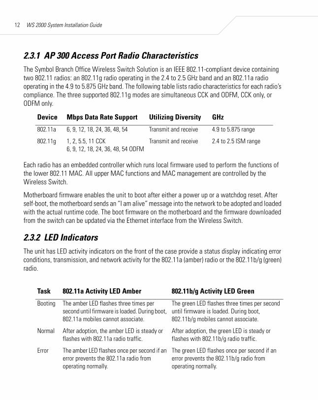
2.3.1 AP 300 Access Port Radio CharacteristicsThe Symbol Branch Office Wireless Switch Solution is an IEEE 802.11-compliant device containing two 802.11 radios: an 802.11g radio operating in the 2.4 to 2.5 GHz band and an 802.11a radio operating in the 4.9 to 5.875 GHz band. The following table lists radio characteristics for each radio’s compliance. The three supported 802.11g modes are simultaneous CCK and ODFM, CCK only, or ODFM only.
Each radio has an embedded controller which runs local firmware used to perform the functions of the lower 802.11 MAC. All upper MAC functions and MAC management are controlled by the Wireless Switch.
Motherboard firmware enables the unit to boot after either a power up or a watchdog reset. After self-boot, the motherboard sends an “I am alive” message into the network to be adopted and loaded with the actual runtime code. The boot firmware on the motherboard and the firmware downloaded from the switch can be updated via the Ethernet interface from the Wireless Switch.
2.3.2 LED IndicatorsThe unit has LED activity indicators on the front of the case provide a status display indicating error conditions, transmission, and network activity for the 802.11a (amber) radio or the 802.11b/g (green) radio.
Device Mbps Data Rate Support Utilizing Diversity GHz
802.11a 6, 9, 12, 18, 24, 36, 48, 54 Transmit and receive 4.9 to 5.875 range
802.11g 1, 2, 5.5, 11 CCK6, 9, 12, 18, 24, 36, 48, 54 ODFM
Transmit and receive 2.4 to 2.5 ISM range
Task 802.11a Activity LED Amber 802.11b/g Activity LED Green
Booting The amber LED flashes three times per second until firmware is loaded. During boot, 802.11a mobiles cannot associate.
The green LED flashes three times per second until firmware is loaded. During boot, 802.11b/g mobiles cannot associate.
Normal After adoption, the amber LED is steady or flashes with 802.11a radio traffic.
After adoption, the green LED is steady or flashes with 802.11b/g radio traffic.
Error The amber LED flashes once per second if an error prevents the 802.11a radio from operating normally.
The green LED flashes once per second if an error prevents the 802.11b/g radio from operating normally.

Symbol Branch Office Wireless Switch Solu- 13
2.3.2.1 AP 300 Access Port Technical Specifications
Physical Specifications
Power Specifications
Environmental Specifications
Other Specifications
Length 241 mm (9.5 in.)
Width 178 mm (7.0 in.)
Height 51 mm (2.0 in.)
Weight 0.45 kg (1.0 lb.)
Operating Voltage 48VDC typical; 36-57VDC range
Operating Current 100mA to 165mA
Peak Current 250mA
Operating Temperature -20°C to 50°C (-4°F to 122°F)
Operating Humidity 5% to 95% non-condensing
Operating Altitude (max.) 2.4 km (8,000 ft.)
Storage Temperature -40°C to 70°C (-40°F to 158°F)
Storage Humidity 85%
Storage Altitude (max.) 4.6 km (15,000 ft.)
Drop (without antennas) 910 mm (36 in.) to concrete
Electrostatic Discharge +/-15kV air; +/-8kV contact; +/-2kV pin
Plenum Rated UL 2043
Note: The AP 300 Access Port (WSAP-5110-100-WW) supports UNII band 1.

3
Installing the Branch OfficeWireless System Solution
3.1 The Installation ProcessThe Symbol Branch Office Wireless Switch Solution can operate in various locations, allowing placement in most environments. The basic installation steps are:
1. Select a site (desk, wall, or rack) for installation of the wireless switch.2. Install the switch in selected location using the instructions specifically for that location
type, found in Section 3.3, Installing the WS 2000 Wireless Switch.
Connect the wireless switch to the power supply early in the installation process for easy access to the connector; however, do not plug the power supply into a power source before installation is complete.

Installing the Branch Office Wireless System 15
3. Plug the wireless switch into the wall power socket.4. Lock device to desk, wall, or rack using lock port on the switch.5. Install Access Port in selected location using the instructions specifically for that location
type, found in Section 3.4, Installing the AP 300 Access Port.6. Plug in WAN and LAN (Access Port) connections to the switch and turn on switch.7. See Chapter 4, Configuring the WS 2000 Wireless Switch for information on how to
configure the switch for your network and devices.
3.2 WarningsBefore installing and operating any equipment, review this document for any hazards associated with installation and use of the device. Also, review standard practices for preventing accidents.
• Only trained and qualified personnel should install this equipment.• Read all installation instructions and site survey reports and verify correct equipment
installation before connecting the system to its power source.• Remove any jewelry (rings, watches, necklaces, etc.) while installing this equipment.• Install this equipment in racks with appropriate dimensions and weight allowances.• Verify that racks are anchored and do not install in a way that can cause the equipment to
tip over and break away from its mountings. Damage to the devices or bodily injury can occur from equipment that was not appropriately mounted and secured.
• Verify the unit is grounded before connecting to the power source. Connect all power cords to a properly wired and grounded electrical circuit.
• Verify that any device connected to this unit is properly wired and grounded.• Verify that connecting power circuits have appropriate overload protection.• Attach only approved power cords and cables to the devices.• Verify that the power connector is accessible at all times during the operation of the
equipment.• Verify that the power circuit for the unit is grounded, can provide the required power, and is
not overloaded.• Do not work with equipment power circuits in dimly lit spaces.
WS 2000 System Installation Guide16
• Do not install this equipment or work with its power circuits during thunderstorms or weather conditions where power surges can exist.
• Verify that there is adequate ventilation around the devices and that ambient temperatures meet equipment operation specifications.
• Verify uninterruptible power sources—install the socket nearby and easily accessible to the equipment.
• For equipment that needs to be plugged in, position equipment near an easily accessible socket-outlet.
3.3 Installing the WS 2000 Wireless Switch
3.3.1 Selecting a Site for InstallationThe WS 2000 Wireless Switch can be installed on a flat surface, on a wall, or in a rack. In selecting a site, the installer should verify that the location has access to:
• A grounded outlet—preferably one that has surge protection or is protected by a uninterruptible power supply (UPS)
• The WAN connection for the switch (whether a modem, router, switch, or hub) (The wireless switch comes with a 6 ft. (1.829 m) patch cable for this purpose, but the installer is not required to use either that cable or stay within that distance.)
• The LAN connections for this switch (whether Access Port, switch, hub, or computer)
Ensure that this location meets optimal temperature and environmental requirements for the operation of this device (see Section 2.2.1, WS 2000 Technical Specifications).
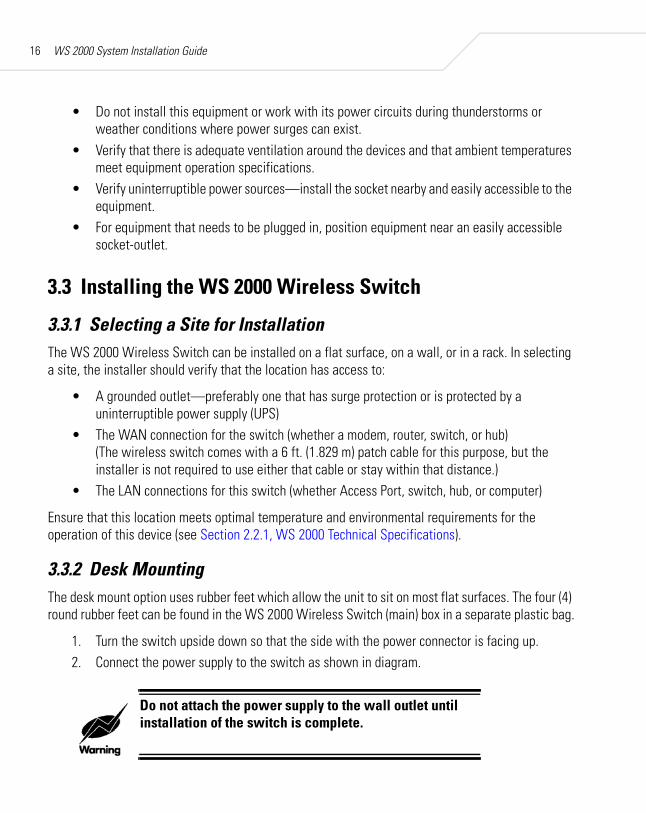
3.3.2 Desk MountingThe desk mount option uses rubber feet which allow the unit to sit on most flat surfaces. The four (4) round rubber feet can be found in the WS 2000 Wireless Switch (main) box in a separate plastic bag.
1. Turn the switch upside down so that the side with the power connector is facing up. 2. Connect the power supply to the switch as shown in diagram.
Do not attach the power supply to the wall outlet until installation of the switch is complete.
Installing the Branch Office Wireless System 17
3. Remove the backings from the four (4) rubber feet and stick them to the switch on the four circles, as shown. The feet will be right next to the four plugs.
4. Return the switch to the upright position in the place that you wish it to sit, ensuring that it is sitting evenly on all four rubber feet.
5. Connect the power supply to the wall outlet.
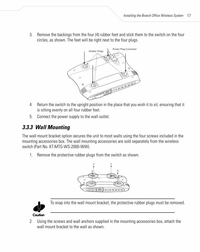
3.3.3 Wall MountingThe wall mount bracket option secures the unit to most walls using the four screws included in the mounting accessories box. The wall mounting accessories are sold separately from the wireless switch (Part No. KT-MTG-WS-2000-WW).
1. Remove the protective rubber plugs from the switch as shown.
To snap into the wall mount bracket, the protective rubber plugs must be removed.
2. Using the screws and wall anchors supplied in the mounting accessories box, attach the wall mount bracket to the wall as shown.
Power Plug ConnectorRubber Plugs

WS 2000 System Installation Guide18
Align the RJ-45 ports on the switch with the embossed port symbols on the front of the wall mount bracket.
3. Connect the power supply to the switch, but not to the wall outlet.
Do not attach the power supply to the wall outlet until installation of the switch is complete.
4. Align the holes on the bottom of the switch (where the plugs used to be) with the plastic guides on the mounting bracket (circled in diagram below).
5. Push the switch into place on the bracket. You should hear a snap indicating that the switch is securely attached to the bracket.
6. Connect the power supply to the wall outlet.
Wall
Embossed Port Symbols

Installing the Branch Office Wireless System 19
The wall mount bracket is designed to allow threading of cables underneath the bracket. There is space underneath the wall mount bracket to hold cables. Cables can be placed above, between, or below the attachment points.
3.3.4 Rack MountingThe rack mounting option provides a 1U bracket to the switch allowing it to be mounted in a standard rack. Rack mounting accessories are sold separately from the wireless switch (Part No. KT-MTG-WS-2000-WW).
1. Connect the power supply to the connector on the bottom-rear of the switch.
Do not attach the power supply to the wall outlet until installation of the switch is complete.
2. Attach 1U bracket to rack using four of the six screws provided in the mounting accessories box.
3. Slide the back of the switch (with the front of the switch tilted slightly upward) between theguides at the rear of the bracket, until the two retaining clips slide into slots in the back of the switch, as shown.
4. Set the front side of the switch down on to the bracket making sure that the locator tabs in the front of the bracket slide into the two slots on the bottom front of the switch.
Guides
Retaining Clips
Locator Tabs
Attach to Rack
FrontBack
Guide
Front

WS 2000 System Installation Guide20
5. Attach the rack bezel to the bracket. To do this, tilt the bezel forward and place the T-shaped tabs on the lower edge of the bezel just behind the lip on the front of the rack bracket. (You will see two holes in the lip where they attach). Pull the bezel forward slightly and the T-tabs should lock into place.
6. Using the remaining two screws provided in the mounting accessories box attach the bezel to the rack bracket.
7. Connect the power supply to the wall outlet and turn on switch when appropriate.
3.3.5 Securing the Network SwitchThe WS 2000 Wireless Switch comes with a lock port that is compatible with most locking systems. The lock port is on the rear of the switch, opposite the power connector. In order to have clear access, We suggest that you lock the wireless switch in place before you plug in WAN and LAN cables.
see Detail A
Detail A
T-shaped tab

Installing the Branch Office Wireless System 21
3.3.6 Using the CompactFlash® SlotThe WS 2000 Wireless Switch has a CompactFlash® slot which provides for storage and delivery of application to mobile units wit AirBEAM Smart Client. When not being used for this purpose, the rubber plug provided with the switch should remain in the slot.
3.3.7 Connecting Switch to WAN and LAN (RJ-45) Ports
The WS 2000 Wireless Switch provides six LAN ports and one WAN port. LAN Ports 1-4 provide 802.3af PoE support. Connect the Ethernet cable that will go into the Access Port into one of these four LAN ports.
Lock Port
Power Connector
Back
Rubber Plug forCompactFlash Slot®
Standard Ethernet Ports
802.3af LAN Ports (PoE)
WAN Port Power LED
WS 2000 System Installation Guide22
The WAN port is capable of hooking up to a DSL or cable modem, or to any Layer 2/3 network device.
Plug devices into RJ-45 ports using standard CAT-5 patch cables.
The power LED flashes during startup and remains lit during normal operation.
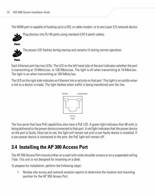
Each Ethernet port has two LEDs. The LED on the left hand side of the port indicates whether the port is transmitting at 10 Mbits/sec. or 100 Mbits/sec. The light is off when transmitting at 10 Mbit/sec. The light is on when transmitting at 100 Mbits/sec.
The LED on the right side indicates an Ethernet link or activity on that port. This light is on solidly when a link to a device is made. The light flashes when traffic is being transferred over the line.
The four ports that have PoE capabilities also have a PoE LED. A green light indicates that 48 volts is being delivered to the power device connected to that port. A red light indicates that the power device on the port is faulty. Once set to red, the light will remain red until a non-faulty device is installed. If a non-power device is connected to the port, the PoE light will remain off.
3.4 Installing the AP 300 Access PortThe AP 300 Access Port mounts either on a wall with wide-shoulder screws or on a suspended ceiling T-bar. This unit is not designed for mounting on a desk.
To prepare for installation, perform the following steps:
1. Review site survey and network analysis reports to determine the location and mounting position for the AP 300 Access Port.
PoE
10/100 Link/Activity

Installing the Branch Office Wireless System 23
2. Connect a CAT-5 cable to a compatible 802.3af power source and run the cable to the installation site. Ensure that there is sufficient slack on the cable to perform the installation steps.
3.4.1 Wall MountingWall mounting requires hanging the AP 300 Access Port along its width or length using the pair of slots on the bottom of the unit. The AP 300 can be mounted onto any plaster, wood, or cement wall surface using the provided wall anchors, when necessary. The illustration shows a lengthwise mount.
3.4.1.1 Wall Mount Hardware
• Two Phillips pan head self-tapping screws• Two wall anchors• Safety wire (recommended) and security cable (optional)
In the event that the original mounting screws are lost, the following screws can be used instead: (ANSI Standard) #6-18 x 0.875in. Type A or AB Self-Tapping Screw, or (ANSI Standard Metric) M3.5 x 0.6 x 20mm Type D Self-Tapping Screw
3.4.1.2 Wall Mount Procedure
1. Orient the case on the wall by its width or length.

WS 2000 System Installation Guide24
2. Using the arrows on one edge of the case as guides, move the edge to the midline of the mounting area and mark points on the midline for the screws.
3. At each point, drill a hole in the wall, insert an anchor, screw into the anchor the wall mounting screw and stop when there is 1mm between the screw head and the wall.
When pre-drilling a hole the recommended hole size is 2.8mm (0.11in.) if the screws are going directly into the wall and 6mm (0.23in.) if the provided wall anchors are being used.
4. If required, loop a safety wire—with a diameter of at least .101 cm (.04 in.) but no more than 0.158 cm (.0625 in.)—around the tie point and secure the loop.
5. If required, install and attach a security cable to the unit’s lock port.6. Attach the Ethernet cable to the unit and to a switch with an 802.3af-compatible power
source.
7. Place the middle of each of the case’s mount slots over the screw heads.8. Slide the case down along the mounting surface to hang the mount slots on the screw
heads.9. Verify the unit has power by observing that the LEDs are lit or flashing.
3.4.2 Suspended Ceiling T-Bar MountCeiling mount requires holding the AP 300 Access Port up against a T-bar of a suspended ceiling grid and twisting the case onto the T-bar.
3.4.2.1 Ceiling Mount Hardware
• Safety wire (recommended) and security cable (optional)
4
6
5

Installing the Branch Office Wireless System 25
3.4.2.2 Ceiling Mount Procedure
1. If required, loop a safety wire—with a diameter of at least 1.01 cm (.04 in.), but no more than 0.158 cm (.0625 in.) —through the tie post and secure the loop.
2. If required, install and attach a security cable to the lock port.3. Plug the Ethernet cable into the unit and to a switch with an 802.3af-compatible power
source.
4. Face the bottom of the T-bar with the back of the case.5. Orient the case by its length and the length of the T-bar.6. Rotate the case in place 45 degrees clockwise, or about 10 o’clock.7. Push the back of the case onto the bottom of the T-bar.8. Rotate the case 45 degrees counter-clockwise. The clips click as they fasten to the T-bar.
9. Verify the unit has power by observing the LEDs.
1
3
2
WS 2000 System Installation Guide26
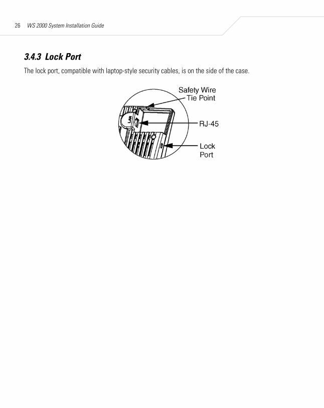
3.4.3 Lock PortThe lock port, compatible with laptop-style security cables, is on the side of the case.

4
Configuring theWS 2000 Wireless Switch
Getting Started with the WS 2000 Wireless SwitchThis section provides just enough instruction to set up the WS 2000 Wireless Switch, connect an Access Port, and test communications with a single mobile unit and the wide area network (WAN). The configuration suggestions made here are just the minimum needed to test the hardware. It is assumed that the switch and the Access Port are already installed using the instructions found earlier in this guide. Once finished with this section, additional configuration settings are required. This section covers the following topics:
• Setting up administrative communication with the switch
• Setting the basic switch settings• Enabling Subnet1• Configuring Subnet1
• Configuring the WAN interface• Enabling wireless LANs (WLANs)• Configuring WLAN security• Testing connectivity
WS 2000 System Installation Guide28
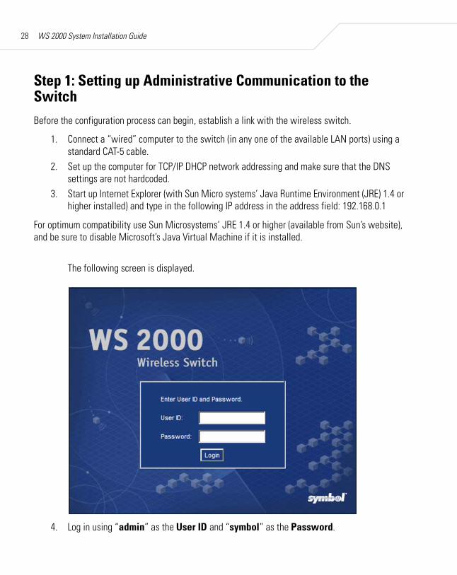
Step 1: Setting up Administrative Communication to the SwitchBefore the configuration process can begin, establish a link with the wireless switch.
1. Connect a “wired” computer to the switch (in any one of the available LAN ports) using a standard CAT-5 cable.
2. Set up the computer for TCP/IP DHCP network addressing and make sure that the DNS settings are not hardcoded.
3. Start up Internet Explorer (with Sun Micro systems’ Java Runtime Environment (JRE) 1.4 or higher installed) and type in the following IP address in the address field: 192.168.0.1
For optimum compatibility use Sun Microsystems’ JRE 1.4 or higher (available from Sun’s website), and be sure to disable Microsoft’s Java Virtual Machine if it is installed.
The following screen is displayed.
4. Log in using “admin” as the User ID and “symbol” as the Password.

Configuring the WS 2000 Wireless Switch 29
5. If the login is successful, the following dialog window is displayed.
Enter a new admin password in both fields, and click the Update Password Now button. Once the admin password has been updated, the System Settings screen is displayed.

WS 2000 System Installation Guide30
Step 2: Setting the Basic Switch Settings1. Enter a System Name for the wireless switch. The specified name appears in the lower-left
corner of the configuration screens, beneath the navigation tree. This name can be a useful reminder if multiple Symbol wireless switches are being administered.
2. Enter a text description of the location of the switch in the System Location field. This text is used as a reminder to the network administrator and is also used to set the location variable if the switch is administered using SNMP.
3. Enter an email address for the administrator in the Admin Email Address field. The switch uses this address for sending SNMP-related and other administration-related messages to the administrator.
4. Select the Country for the switch from the drop-down menu. Selecting the correct country is extremely important. Each country has its own regulatory restrictions concerning electromagnetic emissions and the maximum RF signal strength that can be transmitted by Access Ports. To ensure compliance with national and local laws, be sure to set this field accurately.
5. Click Apply to save changes. Unapplied changes are lost if the administrator navigates to a different screen.
The WS 2000 switch is shipped with an open default SNMP configuration: community: public OID: 1.3.6.1 Access: Read-onlycommunity: private OID: 1.3.6.1 Access: Read-write
If your switch has these settings, it is important to change them immediately; otherwise, users on the same network will have read-write access to the switch through the SNMP interface. Select System Configuration --> SNMP Access from the left menu to examine the settings and change them if necessary.
Step 3: Configuring the LAN InterfaceThe first step of network configuration process is to figure out the topology of the LAN. The WS 2000 Wireless Switch allows the administrator to enable and configure four different subnets. The administrator can assign an IP address, port associations, DHCP settings, and security settings to each subnet.

Configuring the WS 2000 Wireless Switch 31
Enable Subnet1Select LAN under the Network Configuration group from the left menu. Use the LAN configuration screen to view a summary of physical-port addresses and wireless LANs (WLANs) associated with the four supported subnets, and to enable or disable each configured subnet.
1. In the LAN screen, the administrator can enable up to four subnets. Make sure that the checkbox to the left of the Subnet1 line is enabled.
Each enabled subnet shows up in the directory tree in the left column of the configuration screens. Consider disabling a previously configured subnet if its assigned ports are no longer in use, or to consolidate the LAN’s communications on fewer subnets.
The rest of the information on this screen is summary information— it is collected from other screens (such as the subnet configuration screens) where the administrator can set the data.
Network Network (subnet) name is a descriptive string that should describe the subnet’s function. The WS 2000 Network Management System uses subnet names throughout the configurations screens.
WS 2000 System Installation Guide32
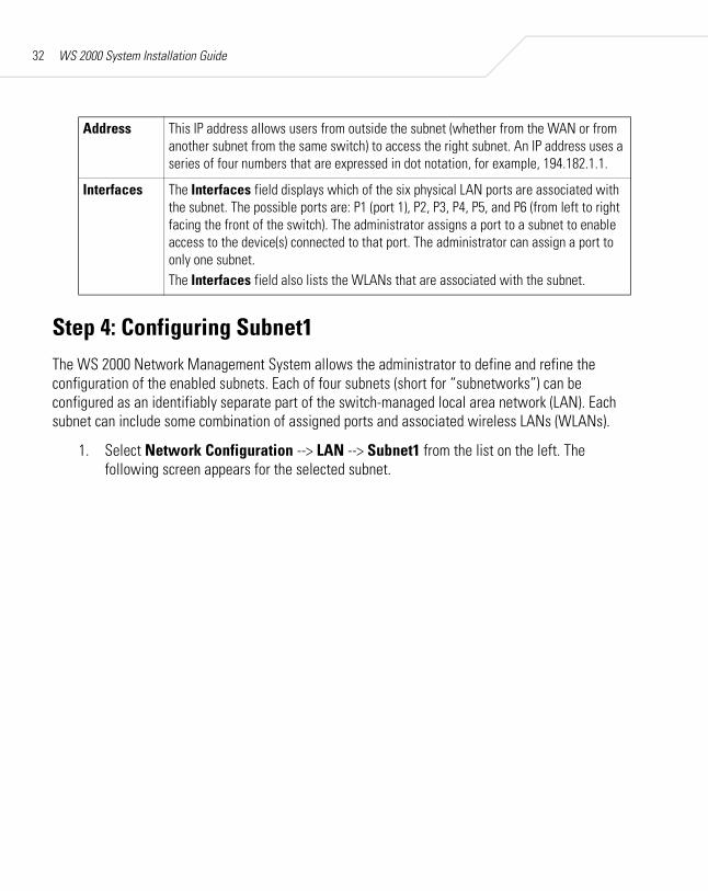
Step 4: Configuring Subnet1The WS 2000 Network Management System allows the administrator to define and refine the configuration of the enabled subnets. Each of four subnets (short for “subnetworks”) can be configured as an identifiably separate part of the switch-managed local area network (LAN). Each subnet can include some combination of assigned ports and associated wireless LANs (WLANs).
1. Select Network Configuration --> LAN --> Subnet1 from the list on the left. The following screen appears for the selected subnet.
Address This IP address allows users from outside the subnet (whether from the WAN or from another subnet from the same switch) to access the right subnet. An IP address uses a series of four numbers that are expressed in dot notation, for example, 194.182.1.1.
Interfaces The Interfaces field displays which of the six physical LAN ports are associated with the subnet. The possible ports are: P1 (port 1), P2, P3, P4, P5, and P6 (from left to right facing the front of the switch). The administrator assigns a port to a subnet to enable access to the device(s) connected to that port. The administrator can assign a port to only one subnet.The Interfaces field also lists the WLANs that are associated with the subnet.

Configuring the WS 2000 Wireless Switch 33
2. Check to make sure that all the ports and WLAN1 are selected for this subnet. WLAN1 should automatically be included if the switch and the access port are communicating properly. If WLAN1 is not present in the list, check: • The power to the Access Port• The connections between the switch and the access port• The LEDs to make sure that lights are on and flashing
3. For this initial configuration, ensure that This interface is a DHCP Server is enabled. If so, the switch sets the IP addresses automatically for the mobile devices. This value can be changed at any time in the future. All other default settings are fine for the system test.
DHCP is a protocol that includes mechanisms for IP address allocation and delivery of host-specific configuration parameters from a DHCP server to a host. Some of these parameters are IP address, network mask, and gateway. The switch includes internal DHCP server and client features, and the subnet’s interface can use either capability.
4. Click the Apply button if any changes were made.
WS 2000 System Installation Guide34
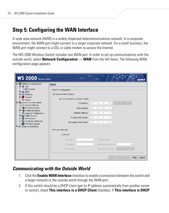
Step 5: Configuring the WAN InterfaceA wide area network (WAN) is a widely dispersed telecommunications network. In a corporate environment, the WAN port might connect to a larger corporate network. For a small business, the WAN port might connect to a DSL or cable modem to access the Internet.
The WS 2000 Wireless Switch includes one WAN port. In order to set up communications with the outside world, select Network Configuration --> WAN from the left menu. The following WAN configuration page appears.
Communicating with the Outside World1. Click the Enable WAN Interface checkbox to enable a connection between the switch and
a larger network or the outside world through the WAN port.2. If this switch should be a DHCP client (get its IP address automatically from another server
or switch), check This interface is a DHCP Client checkbox. If This interface is DHCP

Configuring the WS 2000 Wireless Switch 35
Client is checked, the switch is limited to one WAN IP address. This choice is required when:• The host router or switch on the WAN is communicating with the WS 2000 Wireless
Switch using DHCP.• The switch is interfacing with an Internet Service Provider (ISP) that uses DHCP
addressing.
This setting is independent from the DHCP settings for the switch’s internal subnets.
3. If This interface is DHCP Client is not checked, fill in the information in this area. To find out the information to enter into these fields, contact the network administrator or the ISP that provided the cable modem or DSL router. All the fields below take standard IP addresses of the form xxx.xxx.xxx.xxx.• The IP Address refers to the IP address that the outside world uses to address the WS
2000 Wireless Switch.• Click the More IP Addresses button to specify additional static IP addresses for the
switch. Additional IP addresses are required when users within the LAN need dedicated IP addresses, or when servers in the LAN need to be accessed (addressed) by the outside world. The pop-up window allows the administrator to enter up to eight WAN IP addresses for the switch.
• The Subnet Mask is the mask used for the WAN.• The Default Gateway is the address of the device that provides the connection to the
WAN (often a cable modem or DSL router).• The two DNS Server fields specify DNS addresses of servers that can translate domain
names, such as www.symbol.com, into IP addresses that the network uses when passing information. The Secondary DNS Server acts as a backup to the Primary DNS Server when the primary server is not responding.
Setting Up Point-to-Point over Ethernet (PPPoE) CommunicationPPPoE provides the ability to connect a network of hosts through a simple device to a remote access concentrator. Many DSL providers require that their clients communicate using this protocol. The facility allows the ISP to control access, billing, and type of service provided to clients on a per-user or per-site basis. Check with the network administrator or ISP to determine whether to enable this feature, and, if so, find out the username and password required for authentication.

WS 2000 System Installation Guide36
1. Check Enable in the PPP over Ethernet area to enable the PPPoE protocol for high-speed connections.
2. Enter the Username and Password required for authentication. The username and password are for the switch’s router to use when connecting to the ISP. When the Internet session starts, the ISP authenticates the username.
3. Set the Idle Time to an appropriate number. This number is the amount of time the PPPoE connection will be idle before it disconnects. The 10000 second (default idle time is appropriate for most situations).
4. Check Keep Alive to instruct the switch to continue occasional communications over the WAN even when client communications to the WAN are idle. Some ISPs terminate inactive connections, while others do not. In either case, enabling Keep-Alive mode keeps the switch’s WAN connection alive, even when there is no traffic. If the ISP drops the connection after so much idle time, the switch automatically reestablishes the connection to the ISP.
5. Select the appropriate WAN authentication method from the drop-down menu. Collect this information from the network administrator. Select between None, PAP, CHAP, or PAP or CHAP.
6. Click the Apply button to save changes.
Step 6: Enabling Wireless LANs (WLANs)The WS 2000 Wireless Switch works either in a wired or wireless environment; however, the power of the switch is associated with its support of wireless networks. In order to use the wireless features of the switch, the administrator needs to enable up to four wireless LANs (WLANs).
CHAP A type of authentication in which the person logging in uses secret information and some special mathematical operations to come up with a number value. The server the person is logging into knows the same secret value and performs the same mathematical operations. If the results match, the person is authorized to access the server. One of the numbers in the mathematical operation is changed after every log-in, to protect against an intruder secretly copying a valid authentication session and replaying it later to log in.
PAP An identity verification method used to send a username and password over a network to a computer that compares the username and password to a table listing authorized users. This method of authentication is less secure, because the username and password travel as clear text that a hacker could read.

Configuring the WS 2000 Wireless Switch 37
To start the WLAN configuration process, select the Network Configuration --> Wireless item from the left menu. The following Wireless summary screen appears.
Wireless Summary AreaThe top portion of the window displays a summary of the WLANs that are currently defined. This is the screen in which the administrator can enable or disable a WLAN. At first, four WLANs are listed WLAN1, WLAN2, WLAN3, and WLAN4; however, only WLAN1 is enabled.
1. Verify that WLAN1 is enabled (checked) and associated with Subnet1.2. Verify that Access Port 1 is shown in the Access Ports Adopted field to the right. If it is
not, verify the connection between the switch and the Access Port.
The current settings for the associated Subnet and adopted Access Ports are displayed on this screen; however, the screen associated with each WLAN (under Network Configuration --> Wireless) is where the settings and rules for adopting Access Ports can be modified.

WS 2000 System Installation Guide38
Use the Access Port Adoption area to assign Access Ports to a particular WLAN. The switch can adopt up to six Access Ports at a time, but the list of allowed Access-Port addresses (displayed in this area) can exceed six in number. A dual-radio 802.11a/b Access Port counts as one Access Port with respect to the maximum allowed; however, each radio is listed as a separate Access Port.
This adoption list identifies each Access Port by its Media Access Control (MAC) address. This address is the Access Port’s hard-coded hardware number that is printed on the bottom of the device. An example of a MAC address is 00:09:5B:45:9B:07.
The default setting associates all adopted Access Ports with WLAN1.
Step 7: Configuring WLAN SecurityIn the previous step, the administrator set parameters for each WLAN that fine tune the performance of the WLAN. In addition, the administrator can set the type and level of security for each WLAN. These security measures do not control communications from the WAN; instead, they control communication from the clients within the WLAN.
In the Network Configuration --> Wireless --> <WLAN name> --> <WLAN Name> --> Security screen, the administrator can set the user authentication method and the encryption method, as well as define a set of rules that control which MUs can communicate through the WLAN.

Configuring the WS 2000 Wireless Switch 39
Setting the Authentication MethodThe authentication method sets a challenge-response procedure for validating user credentials such as username, password, and sometimes secret-key information. The WS 2000 Wireless Switch provides two methods for authenticating users: 802.1x EAP and Kerberos. The administrator can select between these two methods. For testing connectivity, WLAN security is not an issue, so there is not reason to enable authentication—the default setting (No Authentication) is sufficient.
Setting the Encryption MethodEncryption applies a specific algorithm to data to alter its appearance and prevent unauthorized reading. Decryption applies the algorithm in reverse to restore the data to its original form. Sender and receiver employ the same encryption/decryption method.
Wired Equivalent Privacy (WEP) is a security protocol specified in the IEEE Wireless Fidelity (Wi-Fi) standard, 802.11b. WEP is designed to provide a WLAN with a level of security and privacy comparable to that of a wired LAN. WEP might be all that a small-business user needs for the simple

WS 2000 System Installation Guide40
encryption of wireless data. However, networks that require more security are at risk from a WEP flaw. An unauthorized person with a sniffing tool can monitor a network for less than a day and decode its encrypted messages.
For the connectivity test, set WEP 128 encryption. This ensures that communications with the switch are secure enough for this stage. Later on, increasing the security level might be necessary.
1. Select the WEP 128 (104-bit key) option.2. To use WEP encryption with the No Authentication selection, click the WEP Key Settings
button to display a sub-screen for entering keys.
3. Add a key to Key #1, and use that key with the mobile unit. The keys consist of 26 hexadecimal (0-9, A-E) characters. When finished, click the Ok button to close this screen an return to the WLAN Security screen.
4. Click the Apply button in the WLAN Security screen to save changes.
Mobile Unit Access Control List (ACL)This list is used to specify which mobile units can or cannot gain access to the WLAN. The list employs an adoption rule for allowing or denying specific mobile units by way of exception. By default, all mobile units can gain access.
Step 8: Testing ConnectivityAt this point, the switch is set up to allow mobile units.

Configuring the WS 2000 Wireless Switch 41
1. Go to the mobile unit and ensure that it is set up as a DHCP client.2. Set the mobile unit for WEP 128 encryption and set the same key as the one that was
entered in the WEP Key Settings dialog. It may be necessary to reboot the mobile unit after changing the settings.
3. Open a Web browser and type the IP address: 192.168.0.1.
The WS 2000 Switch Management screen should appear. If not, go back to the wired system used to configure the switch and see if the mobile device appears in the MU Stats screen (Status & Statistics --> MU Stats). If it does not appear on the MU Stats screen, recheck the network and WEP settings on the mobile device.
4. In the Web browser, enter a URL for a site (such as www.symbol.com) on the WAN. If the site does not appear, go to the WAN Stats screen (Status & Statistics --> WAN Stats) to review the status of the WAN connection.
Where to Go from Here?Once full connectivity has been verified, the switch can be fully configured to meet the needs of the organization. The Online System Reference has detailed information about how to configure the WS 2000 Wireless Switch. In addition, two case studies are provided on the CD for specific installation examples. These case studies describe the environment, the desired features, and the configuration selections that were made in two different scenarios.
• Case 1: Small Retail Store
(with handheld terminals, wireless printers, wired POS, secured access to in-store server, and public access to WAN)
• Case 2: Small Branch Office
(with 3 WAN IP addresses, VPN passthrough, RADIUS server, and full-access between subnets)

Regulatory Information
All Symbol devices are designed to be compliant with rules and regulations in locations they are sold and will be labeled as required. Any changes or modifications to Symbol Technologies equipment, not expressly approved by Symbol Technologies, could void the user’s authority to operate the equipment.
Use only the approved antennas. Unauthorized antennas, modifications, or attachments could cause damage and may violate regulations.
The AP 300 Access Port is to be used only with Symbol Technologies Wireless Switch.
Country ApprovalsRegulatory markings are applied to the device signifying the radio (s) are approved for use in the following countries: United States, Canada, Australia, Japan, and Europe. Please refer to the Symbol Declaration of Conformity (DoC) for details of other country markings. This is available at http://www2.symbol.com/doc/.
For 2.4 GHz Products: Europe includes, Austria, Belgium, Croatia, Czech Republic, Croatia, Cyprus, Denmark, Estonia, Finland, France, Germany, Greece, Hungary, Iceland, Ireland, Italy, Latvia, Liechtenstein, Lithuania, Luxembourg, Malta, Netherlands, Norway, Poland, Portugal, Slovak Republic, Slovenia, Spain, Sweden, Switzerland, and the United Kingdom.

Configuring the WS 2000 Wireless Switch 43
The use of 5 GHz RLANs has varying restrictions of use; please refer to the Symbol Declaration of Conformity (DoC) for details.
Operation of the AP 300 Access Port without regulatory approval is illegal.
FCC/EU RF Exposure Guidelines
Safety InformationThe device complies with Internationally recognized standards covering Specific Absorption Rate (SAR) related to human exposure to electromagnetic fields from radio devices. It is advisable to use the device only in the normal operating position.
Remote and Standalone Antenna ConfigurationsTo comply with FCC RF exposure requirements, antennas that are mounted externally at remote locations or operating near users at stand-alone desktop or similar configurations must operate with a minimum separation distance of 20 cm from all persons.
Power SupplyThe AP 300 Access Port is powered from a 802.3af compliant power source which is UL approved.
Radio Frequency Interference RequirementsNote: This equipment has been tested and found to comply with the limits for a Class B digital device, pursuant to Part 15 of the FCC rules. These limits are designed to provide reasonable protection against harmful interference in a residential installation. This equipment generates, uses, and can radiate radio frequency energy and, if not installed and used in accordance with the instructions, may
cause harmful interference to radio communications. However, there is no guarantee that interference will not occur in a particular installation. If this equipment does cause harmful interference to radio or television reception, which can be determined by turning the equipment off and on, the user is encouraged to try to correct the interference by one or more of the following measures:
• Reorient or relocate the receiving antenna• Increase the separation between the equipment and receiver• Connect the equipment into an outlet on a circuit different from that to which the receiver is connected• Consult the dealer or an experienced radio/TV technician for help.
Radio Transmitters (Part 15)The AP 300 Access Port complies with Part 15 of the FCC Rules. Operation is subject to the following two conditions: (1) this device may not cause harmful interference, and (2) this device must accept any interference received, including interference that may cause undesired operation.
Tested to Comply
With FCC Standards
For Home or Office Use
Symbol Technologies Inc.

WS 2000 System Installation Guide44
Radio Frequency Interference Requirements—Canada This device is a Class B digital apparatus complies with Canadian ICES-003.
Cet appareil numérique de la classe B est conforme à la norme NMB-003 du Canada.
Radio TransmittersThe AP 300 Access Port complies with RSS 210 of Industry & Science Canada. Operation is subject to the following two conditions: (1) this device may not cause harmful interference and (2) this device must accept any interference received, including interference that may cause undesired operation.
Label Marking: The Term “IC:” before the radio certification only signifies that Industry Canada technical specifications were met.
CE Marking and European Economic Area (EEA)
The use of 2.4 GHz RLANs, for use through the EEA, have the following restrictions:
• Maximum radiated transmit power of 100 mW EIRP in the frequency range 2.400–2.4835 GHz
• France, outside usage is restricted to 2.4–2.454 GHz• Belgium, outside usage is restricted to 2.460–2.4835 GHz• Italy requires a user license for outside usage.
The use of 5 GHz RLANs has varying restrictions for use within the EEA; please refer to the Symbol Declaration of Conformity (DoC) for details at http://www2.symbol.com/doc/.
Power SupplyUse only a Symbol-approved power supply output rated 48VDC. The power supply is certified to EN60950 with SELV outputs.
Hinweis: Benutzen Sie nur eine Symbol Technologies genehmigt Stromversorgung in den Ausgabe: 48VDC. Die Stromversorgung ist bescheinigt nach EN60950 mit SELV Ausgaben.
Statement of ComplianceSymbol Technologies, Inc., hereby, declares that this device is in compliance with the essential requirements and other relevant provisions of Directives 1999/5/EC, 89/336/EEC and 73/23/EEC. Declaration of Conformities may be obtained from http://www2.symbol.com/doc/.
Other Countries• Mexico—Restrict Frequency Range to: 2.450 – 2.4835 GHz.• Sri Lanka—Restrict Frequency Range to: 2.400 – 2.430 GHz.

Service and Support
Service InformationBefore using the unit, it must be configured to operate in the facility’s network and run your applications. If you have a problem running your unit or using your equipment, contact your facility’s Technical or Systems Support. If there is a problem with the equipment, they will contact the Symbol Support Center:
United States 1-800-653-53501-631-738-2400
Canada 905-629-7226
United Kingdom 0800 328 2424 Asia/Pacific +65-6796-9600
Australia 1-800-672-906 Austria/Österreich 1-505-5794-0
Denmark/Danmark 7020-1718 Finland/Suomi 9 5407 580
France 01-40-96-52-21 Germany/Deutschland 6074-49020
Italy/Italia 2-484441 Mexico/México 5-520-1835
Netherlands/Nederland 315-271700 Norway/Norge +47 2232 4375

WS 2000 System Installation Guide46
For the latest version of this guide go to: http://www.symbol.com/manuals/.
Customer SupportSymbol Technologies provides its customers with prompt and accurate customer support. Use the Symbol Support Center as the primary contact for any technical problem, question or support issue involving Symbol products. If the Symbol Customer Support specialists cannot solve a problem, access to all technical disciplines within Symbol becomes available for further assistance and support. Symbol Customer Support responds to calls by e-mail, telephone or fax within the time limits set forth individual contractual agreements.
When contacting Symbol Customer Support, please provide the following information:
• Device serial number• Product name or model number• Software type and version number
North American ContactsInside North America, contact Symbol at:
For sales and product information:
Symbol Technologies, Inc.One Symbol PlazaHoltsville, New York 11742-1300Telephone: 1-631-738-2400/1-800-SCAN 234Fax: 1-631-738-5990
For product support and service:
Symbol Global Support Center:Telephone: 1-800-653-5350, +1-631-738-6213 (Outside North America)Fax: 1-631-738-5410Email: [email protected]
South Africa 11-8095311 Spain/España 91 324 40 00Inside Spain
Sweden/Sverige 84452900 +34 91 324 40 00Outside Spain
Latin AmericaSales Support
1-800-347-0178 Inside US+1-954-255-2610 Outside US
Europe/Mid-EastDistributor Operations
Contact local distributor or call+44 118 945 7360

Configuring the WS 2000 Wireless Switch 47
International ContactsOutside North America, contact Symbol at:Symbol Technologies, Inc.Symbol PlaceWinnersh Triangle, Berkshire, RG41 5TPUnited KingdomTelephone: 0800-328-2424 (Inside UK), +44 118 945 7529 (Outside UK)http://www.symbol.com/services/howto/howto_contact_us.html
Web Support Sites and Additional InformationComprehensive On-line support is available at the MySymbolCare Web-site. Registration is free and a variety of services can be linked through this web-portal.
For warranty and service information, contact the Symbol Support Center: telephone 1-631-738-6213 or 1-800-653-5350; fax: (631) 563-5410; or E-mail: [email protected].
Obtain additional information by contacting Symbol at:
• 1-800-722-6234, inside North America• +1-631-738-5200, in/outside North America• http://www.symbol.com/
MySymbolCare http://www.symbol.com/services/msc/
Symbol Services Homepage http://symbol.com/services/
Symbol Software Updates http://symbol.com/services/downloads/
Symbol Developer Program http://devzone.symbol.com/
Symbol Knowledge Base http://kb.symbol.com/register.asp

WS 2000 System Installation Guide48

Configuring the WS 2000 Wireless Switch 49

72-70601-01Document Revision A October 2004
Symbol Technologies, Inc.One Symbol PlazaHoltsville, New York 11742-1300http://www.symbol.com