
BRAKES - EV Charger News Brakes Front Brakes: Regenerative Brake Cooperative Control Solenoid Valve:...
24
CHASSIS – BRAKES 153CH10 34 BRAKES J DESCRIPTION D An aluminum solid disc brake is used for the front to reduce the weight. D A leading trailing drum brake is used for the rear. D The hydraulic brake booster is used. D Cooperative control of the regenerative brake and hydraulic brake is performed. D An ABS is a standard equipment. D The tire pressure warning system is used. " Specifications A Master Type Single Master Cylinder Diameter mm (in.) 20.64 (0.81) Brake Booster Type Hydraulic Type Solid Disc Front Pad Area cm 2 (in. 2 ) 47.9 (7.42) Front Brake Wheel Cylinder Diameter mm (in.) 54.0 (2.13) Rotor Size (D T)* mm (in.) 301.7 18 (11.88 0.71) Type Leading Trailing Drum Rear Lining Area cm 2 (in. 2 ) 85.4 (13.24) Rear Brake Wheel Cylinder Diameter mm (in.) 20.64 (0.81) Drum Inner Diameter mm (in.) 254 (10.00) Brake Type P & B Valve Brake Control Deflection Point of Hydraulic Pressure KPa (kgf/cm 2 , psi) 254 (10.00) Valve Pressure Reduction Gradient 0.37 P ki Type Drum Parking Brake Size mm (in.) 254 (10.00) Brake Lever Type Floor Lever ABS STD *: D: Outer Diameter, T: Thickness
Transcript of BRAKES - EV Charger News Brakes Front Brakes: Regenerative Brake Cooperative Control Solenoid Valve:...

CHASSIS – BRAKES
153CH10
34
BRAKES
�DESCRIPTION
� An aluminum solid disc brake is used for the front to reduce the weight.
� A leading trailing drum brake is used for the rear.
� The hydraulic brake booster is used.
� Cooperative control of the regenerative brake and hydraulic brake is performed.
� An ABS is a standard equipment.
� The tire pressure warning system is used.
� Specifications �
Master Type SingleMasterCylinder Diameter mm (in.) 20.64 (0.81)
Brake Booster Type Hydraulic
Type Solid Disc
Front Pad Area cm2 (in.2) 47.9 (7.42)FrontBrake Wheel Cylinder Diameter mm (in.) 54.0 (2.13)
Rotor Size (D � T)* mm (in.) 301.7 � 18 (11.88 � 0.71)
Type Leading Trailing Drum
Rear Lining Area cm2 (in.2) 85.4 (13.24)RearBrake Wheel Cylinder Diameter mm (in.) 20.64 (0.81)
Drum Inner Diameter mm (in.) 254 (10.00)
Brake Type P & B ValveBrakeControl Deflection Point of Hydraulic Pressure KPa (kgf/cm2, psi) 254 (10.00)Valve Pressure Reduction Gradient 0.37
P kiType Drum
ParkingBrake
Size mm (in.) 254 (10.00)Brake
Lever Type Floor Lever
ABS STD
*: D: Outer Diameter, T: Thickness
CHASSIS – BRAKES
153CH08
Brake ActuatorControl ValveAssembly
Master Cylinder Pressure Sensor
Front Wheel Cylinder Pressure Sensor
ABSActuator
P & BValve
EVECU
ABS Warning Light
Brake Warning Light
Brake Warning Buzzer
Rear Speed Sensors
Front Speed Sensors
Hydraulic Brake Booster
Pump
Pump MotorRelay
Pump MotorRelay
Solenoid Relay
ABS &Hydraulic
Brake BoosterECU
Stop Light Switch
PressureSwitches(High and Low)
Brake Fluid LevelWarning Switch
RegenerativeBrake Relay
35
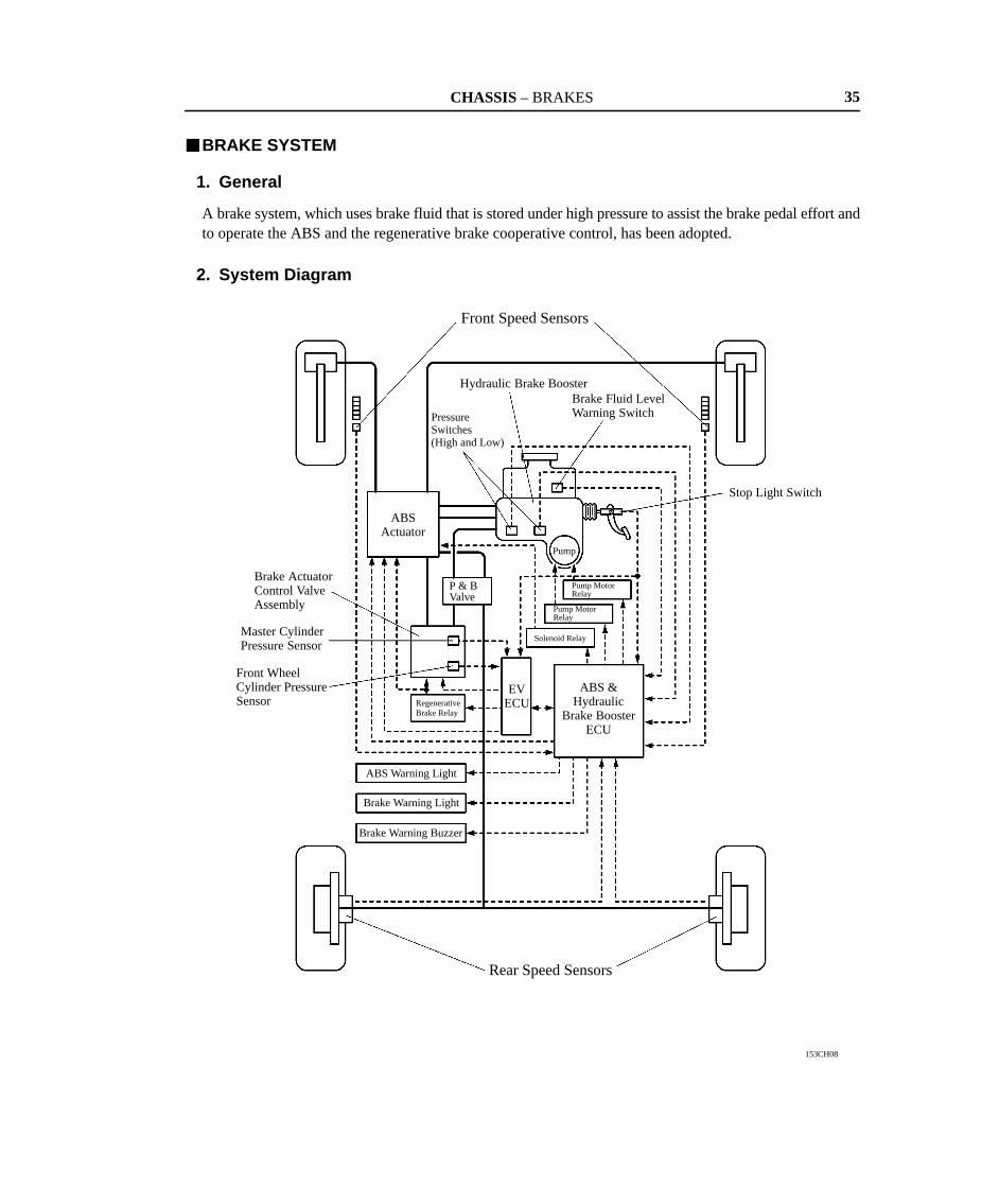
�BRAKE SYSTEM
1. General
A brake system, which uses brake fluid that is stored under high pressure to assist the brake pedal effort andto operate the ABS and the regenerative brake cooperative control, has been adopted.
2. System Diagram

CH
AS
SIS – B
RA
KE
S
153CH35
Speed Sensors
ABS Warning Light,Brake Warning Light
Hydraulic Brake Booster,Brake Fluid Level WarningSwitch, Pressure Switches
EV ECU
ABS Actuator
Brake Actuator ControlValve Assembly,Master Cylinder PressureSensor,Front Wheel CylinderPressure Sensor
Speed Sensor
Pump Motor
Solenoid Relay Speed Sensor Regenerative BrakeRelay
Brake Warning Buzzer
ABS & Hydraulic Brake Booster ECU
Stop Light Switch
Relays
363.Layout of C
omponents
CHASSIS – BRAKES 37
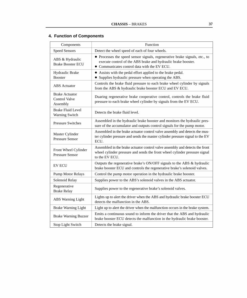
4. Function of Components
Components Function
Speed Sensors Detect the wheel speed of each of four wheels.
ABS & HydraulicBrake Booster ECU
� Processes the speed sensor signals, regenerative brake signals, etc., toexecute control of the ABS brake and hydraulic brake booster.
� Communicates control data with the EV ECU.
Hydraulic BrakeBooster
� Assists with the pedal effort applied to the brake pedal.� Supplies hydraulic pressure when operating the ABS.
ABS ActuatorControls the brake fluid pressure to each brake wheel cylinder by signalsfrom the ABS & hydraulic brake booster ECU and EV ECU.
Brake Actuator Control Valve Assembly
Duaring regenerative brake cooperative control, controls the brake fluidpressure to each brake wheel cylinder by signals from the EV ECU.
Brake Fluid LevelWarning Switch
Detects the brake fluid level.
Pressure SwitchesAssembled in the hydraulic brake booster and monitors the hydraulic pres-sure of the accumulator and outputs control signals for the pump motor.
Master Cylinder Pressure Sensor
Assembled in the brake actuator control valve assembly and detects the mus-ter cylinder pressure and sends the master cylinder pressure signal to the EVECU.
Front Wheel CylinderPressure Sensor
Assembled in the brake actuator control valve assembly and detects the frontwheel cylinder pressure and sends the front wheel cylinder pressure signalto the EV ECU.
EV ECUOutputs the regenerative brake’s ON/OFF signals to the ABS & hydraulicbrake booster ECU and controls the regenerative brake’s solenoid valves.
Pump Motor Relays Control the pump motor operation in the hydraulic brake booster.
Solenoid Relay Supplies power to the ABS’s solenoid valves in the ABS actuator.
RegenerativeBrake Relay
Supplies power to the regenerative brake’s solenoid valves.
ABS Warning LightLights up to alert the driver when the ABS and hydraulic brake booster ECUdetects the malfunction in the ABS.
Brake Warning Light Light up to alert the driver when the malfunction occurs in the brake system.
Brake Warning BuzzerEmits a continuous sound to inform the driver that the ABS and hydraulicbrake booster ECU detects the malfunction in the hydraulic brake booster.
Stop Light Switch Detects the brake signal.
CHASSIS – BRAKES
153CH09
Brake Fluid Level Warning SwitchHydraulic Brake Booster
Reservoir Accumu-lator
Pump and Pump Motor
Pressure Switch (High Pressure)
Pressure Switch (Low Pressure)Relief Valve
Master Cylinder and Brake Booster
Master Cylinder Pressure Sensor
StrokeSimulator
Brake ActuatorControlValve Assembly
P Valve(Rear)
P Valve (Front)
Relief Valve (Rear)
Check Valve
Pressure Booster Piston
Front Wheel Cylinder Pressure Sensor
Relief Valve (FrontHigh Pressure)
Relief Valve(Front Low Pressure)
ABS Control Solenoid Valves
Pressure Holding Valve
Pressure Reduction Valve
ABS Actuator
P & B Valve
Rear Brakes Front Brakes
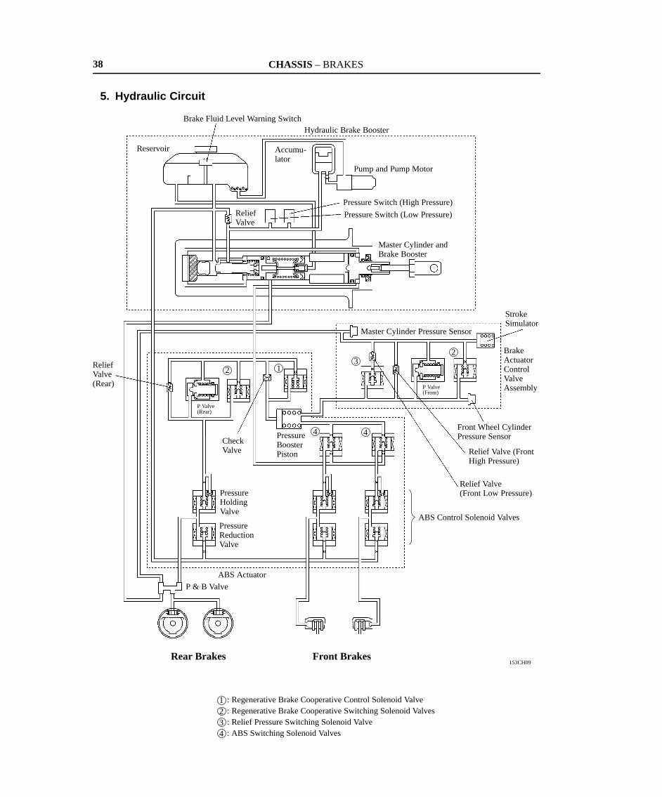
: Regenerative Brake Cooperative Control Solenoid Valve: Regenerative Brake Cooperative Switching Solenoid Valves: Relief Pressure Switching Solenoid Valve: ABS Switching Solenoid Valves
1234
123
2
4 4
38
5. Hydraulic Circuit

CHASSIS – BRAKES 39
6. Construction and Operation
The brake system of RAV4 EV consists of the following components:
Components Function
Pump and Pump Motor Draws up the brake fluid from the reservoir tank andprovides high hydraulic pressure to the accumulator.
AccumulatorStores the hydraulic pressure that was generated bythe pump. The accumulator is filled with high-pressure nitrogen gas.
Pressure Switches
Monitors the hydraulic pressure of the accumulatorand outputs control signals for the pump motor.There are two types: the pressure switch PH forcontrolling the pump, and the pressure switch PL forgiving a warning when the pressure is low.
HydraulicBrake Booster
Relief Valve
Returns the brake fluid to the reservoir tank toprevent excessive pressure if the pump operatescontinuously due to a malfunction of the pressureswitch.
Reservoir Tank Stores the brake fluid.
Brake Fluid Level WarningSwitch Detects the low brake fluid level.
Master Cylinder Generates the hydraulic pressure that is provided tothe wheel cylinders during normal braking.
Brake Booster
Regulates the accumulator pressure in accordancewith the pedal effort that is applied to the brake pedaland introduces this pressure to the booster chamberin order to provide a power assist to the brakes.
Master Cylinder PressureSensor Detects the master cylinder pressure.
Front Wheel Cylinder Pressure Sensor Detects the front wheel cylinder pressure.
Proportioning Valve (Front Side)
Introduces hydraulic pressure to the wheel cylinderswhen the brake pedal is first applied during theoperation of the regenerative brake; thereafter, thisvalve limits the introduction of the hydraulicpressure.
Brake Actuator ControlValve Assembly
Relief ValvesFront High PressureFront Low Pressure
Relieves the hydraulic pressure from the mastercylinder hydraulic circuit to the wheel cylinderhydraulic circuit to ensure braking force after theregenerative braking force has reached its maximumvalue.Because the maximum value of the regenerativebraking force varies by vehicle speed, 2 types ofrelief valves are provided and they are switchedaccording to circumstances.
Regenerative Brake Cooperative Switching Solenoid Valve
Switches the hydraulic path depending on whether ornot the brakes are undergoing cooperative regenera-tive braking.
Relief Pressure Switching Solenoid Valve
Switches the relief pressure from the master cylinderside to the front wheel cylinder side.
Stroke Simulator
While the introduction of the hydraulic pressure fromthe master cylinder to the front wheel cylinders isbeing limited during a regenerative brake operation,the stroke simulator consumes the fluid flow from themaster cylinder by causing the brake pedal togenerate a a stroking movement.

CHASSIS – BRAKES40
Components Function
Proportioning Valve(Rear Side)
Introduces hydraulic pressure to the wheel cylinderswhen the brake pedal is first applied during theoperation of the regenerative brake; thereafter, thisvalve limits the introduction of the hydraulicpressure.
Relief Valve(Rear Side)
Relieves the hydraulic pressure from the mastercylinder hydraulic circuit to the wheel cylinderhydraulic circuit to ensure braking force after theregenerative braking force has reached its maximumvalue.
ABS Actuator
Regenerative Brake Cooperative Switching Solenoid Valve
Switches the hydraulic path depending on whether ornot the brakes are undergoing cooperative regenera-tive braking.Actuator
Regenerative Brake Cooperative Control Solenoid Valve
Switches the hydraulic path to the pressure boosterpiston for introducing the hydraulic pressure that isgenerated in the brake booster to the front wheelcylinders.
Pressure Booster PistonTransmits the hydraulic pressure that is generated inthe brake booster to the front wheel cylinders.
ABS SwitchingSolenoid Valves
Switches the hydraulic path between normal brakingand braking under ABS control.
ABS Control Solenoid ValvesPressure Holding Valves Pressure Reduction Valves
Controls the hydraulic pressure that is applied to thewheel cylinders during ABS control.
CHASSIS – BRAKES
152CH17152CH16
Reservoir Tank
Accumu-lator
Relief Valve
Check ValveTo Master
Cylinder andSolenoidValves Pressure
Switch PL
PressureSwitch PH Pump and
Pump Motor
ABS & HydraulicBrake BoosterECU
Pump MotorRelays
Brake WarningLight
Brake Warning Buzzer
AccumulatorPressure
PressureSwitch PH
ONOFF
OFF
ON
OFF
Open
Close
ON
OFF
PressureSwitch PL
PumpMotor
ReliefValve
Brake WarningLight and BrakeWarning Buzzer
Time
41
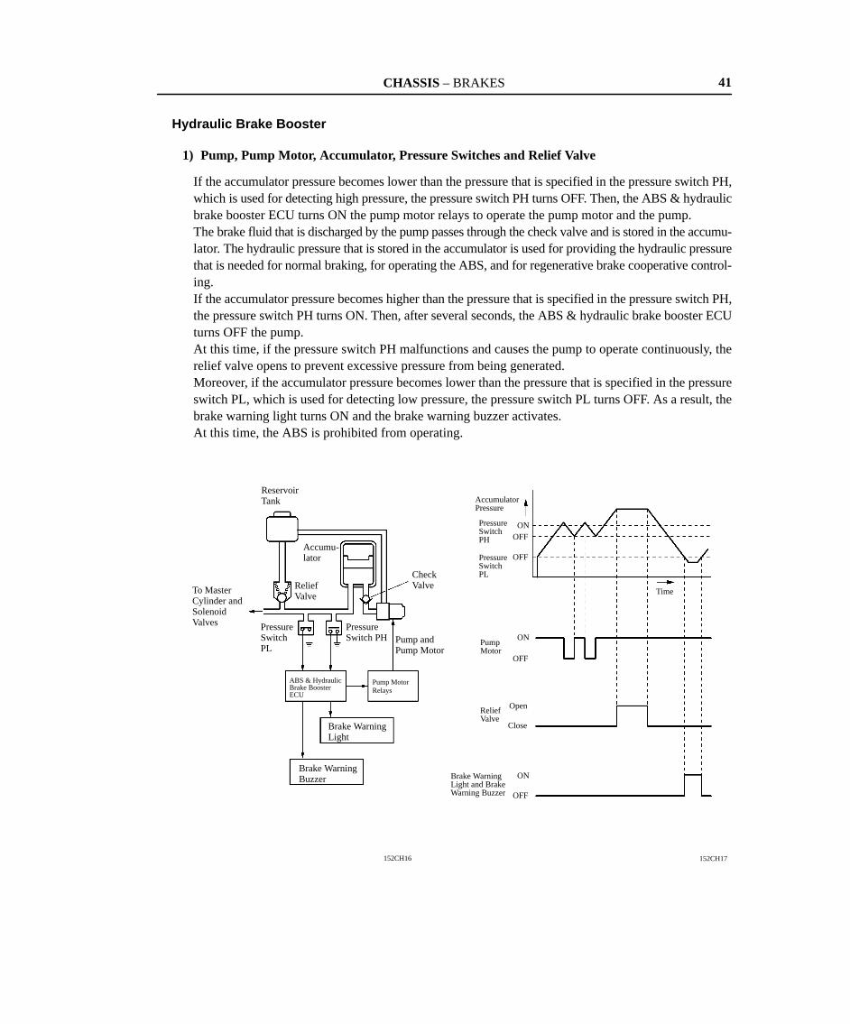
Hydraulic Brake Booster
1) Pump, Pump Motor, Accumulator, Pressure Switches and Relief Valve
If the accumulator pressure becomes lower than the pressure that is specified in the pressure switch PH,which is used for detecting high pressure, the pressure switch PH turns OFF. Then, the ABS & hydraulicbrake booster ECU turns ON the pump motor relays to operate the pump motor and the pump.The brake fluid that is discharged by the pump passes through the check valve and is stored in the accumu-lator. The hydraulic pressure that is stored in the accumulator is used for providing the hydraulic pressurethat is needed for normal braking, for operating the ABS, and for regenerative brake cooperative control-ing.If the accumulator pressure becomes higher than the pressure that is specified in the pressure switch PH,the pressure switch PH turns ON. Then, after several seconds, the ABS & hydraulic brake booster ECUturns OFF the pump.At this time, if the pressure switch PH malfunctions and causes the pump to operate continuously, therelief valve opens to prevent excessive pressure from being generated.Moreover, if the accumulator pressure becomes lower than the pressure that is specified in the pressureswitch PL, which is used for detecting low pressure, the pressure switch PL turns OFF. As a result, thebrake warning light turns ON and the brake warning buzzer activates.At this time, the ABS is prohibited from operating.

CHASSIS – BRAKES
153CH20
Reaction Rod
Rubber Reaction Disc
Spool ValveReturn Spring
Regulator Piston
Master Cylinder Piston
Power Piston
Operating Rod
Operating PortionMaster CylinderRegulator
152CH24
Rubber Reaction Disc
Reaction RodTo Reservoir
From Accumulator
Regulator Piston
From Reservoir
Power Piston
Operating Rod
Master Cylinder Piston
Front BrakeRear Brake
Spool Valve
42
2) Master Cylinder and Brake Booster
a. Construction
� This construction enables the hydraulic pressure that is generated by the brake booster to be applieddirectly to the rear brakes.
� The master cylinder is the center port type single master cylinder, which is used for the front brakesonly.
� The brake booster is integrated with the master cylinder. The operating portion, master cylinder, andregulator are positioned coaxially to achieve a simple and compact construction.
� The operating rod and the power piston are linked directly to transmit the pedal effort that is appliedto the brake pedal.
� The regulator piston and the spool valve are linked directly. A forward (leftward) force generatedby the master cylinder pressure and a rearward (rightward) force generated by the power assist ofthe booster are applied to the regulator piston. Both forces maintain a balance.
� A return spring is provided for the regulator piston to ensure the return of the spool valve.
� Cross-Sectional Drawing �
� Simplified Drawing �
CHASSIS – BRAKES
AB
152CH25
Rubber Reaction Disc
Reaction Rod
To Reservoir
Spool Valve
From Accumulator
Regulator Piston
From Reservoir
Power Piston
Operating Rod
Booster Chamber
Master Cylinder Piston
Return SpringTo Front Brake
ReturnSpring
A BTo Rear Brake
152CH26
Rubber Reaction Disc
Reaction RodTo Reservoir
From Accumulator
Regulator PistonFrom Reservoir
Power Piston
Master Cylinder PistonBooster ChamberTo Rear
BrakeTo FrontBrakeSpool Valve
43
b. Operation
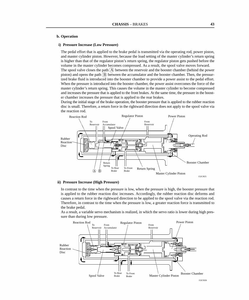
i) Pressure Increase (Low Pressure)
The pedal effort that is applied to the brake pedal is transmitted via the operating rod, power piston,and master cylinder piston. However, because the load setting of the master cylinder’s return springis higher than that of the regulator piston’s return spring, the regulator piston gets pushed before thevolume in the master cylinder becomes compressed. As a result, the spool valve moves forward.The spool valve closes the path between the reservoir and the booster chamber (behind the powerpiston) and opens the path between the accumulator and the booster chamber. Then, the pressur-ized brake fluid is introduced into the booster chamber to provide a power assist to the pedal effort.When the pressure is introduced into the booster chamber, the power assist overcomes the force of themaster cylinder’s return spring. This causes the volume in the master cylinder to become compressedand increases the pressure that is applied to the front brakes. At the same time, the pressure in the boost-er chamber increases the pressure that is applied to the rear brakes.During the initial stage of the brake operation, the booster pressure that is applied to the rubber reactiondisc is small. Therefore, a return force in the rightward direction does not apply to the spool valve viathe reaction rod.
ii) Pressure Increase (High Pressure)
In contrast to the time when the pressure is low, when the pressure is high, the booster pressure thatis applied to the rubber reaction disc increases. Accordingly, the rubber reaction disc deforms andcauses a return force in the rightward direction to be applied to the spool valve via the reaction rod.Therefore, in contrast to the time when the pressure is low, a greater reaction force is transmitted tothe brake pedal.As a result, a variable servo mechanism is realized, in which the servo ratio is lower during high pres-sure than during low pressure.
CHASSIS – BRAKES
B A
152CH27
A B
To Reservoir
From Accumulator
Regulator Piston
From Reservoir
To Front Brake
To Rear Brake
Spool Valve
152CH28
A
To Reservoir
From Accumulator
Regulator Piston
To Reservoir
Booster Chamber
From Front Brake
From Rear Brake
Spool Valve
44
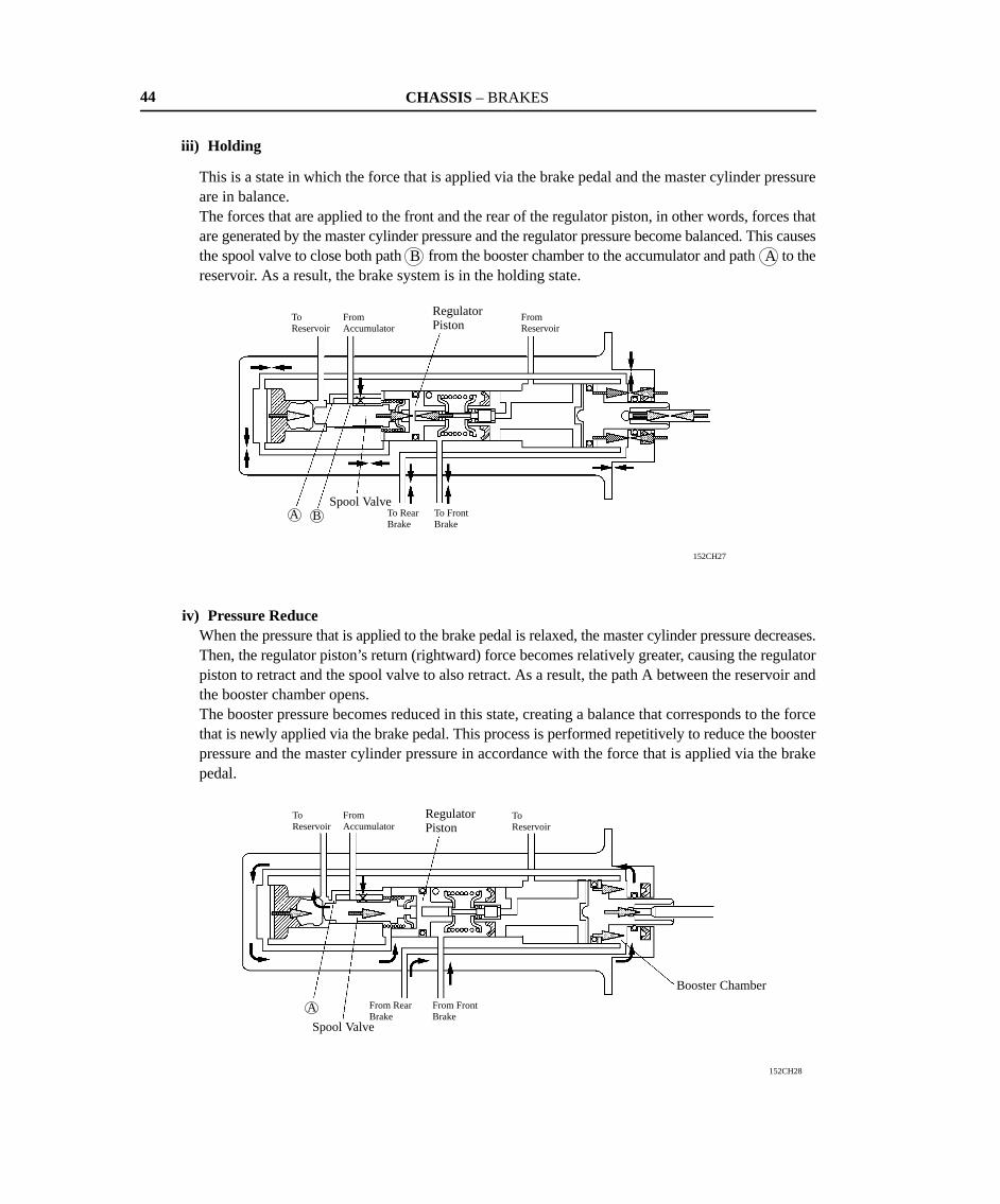
iii) Holding
This is a state in which the force that is applied via the brake pedal and the master cylinder pressureare in balance.The forces that are applied to the front and the rear of the regulator piston, in other words, forces thatare generated by the master cylinder pressure and the regulator pressure become balanced. This causesthe spool valve to close both path from the booster chamber to the accumulator and path to thereservoir. As a result, the brake system is in the holding state.
iv) Pressure ReduceWhen the pressure that is applied to the brake pedal is relaxed, the master cylinder pressure decreases.Then, the regulator piston’s return (rightward) force becomes relatively greater, causing the regulatorpiston to retract and the spool valve to also retract. As a result, the path A between the reservoir andthe booster chamber opens.The booster pressure becomes reduced in this state, creating a balance that corresponds to the forcethat is newly applied via the brake pedal. This process is performed repetitively to reduce the boosterpressure and the master cylinder pressure in accordance with the force that is applied via the brakepedal.
CHASSIS – BRAKES
152CH29
From Reservoir
To Front Brake
45
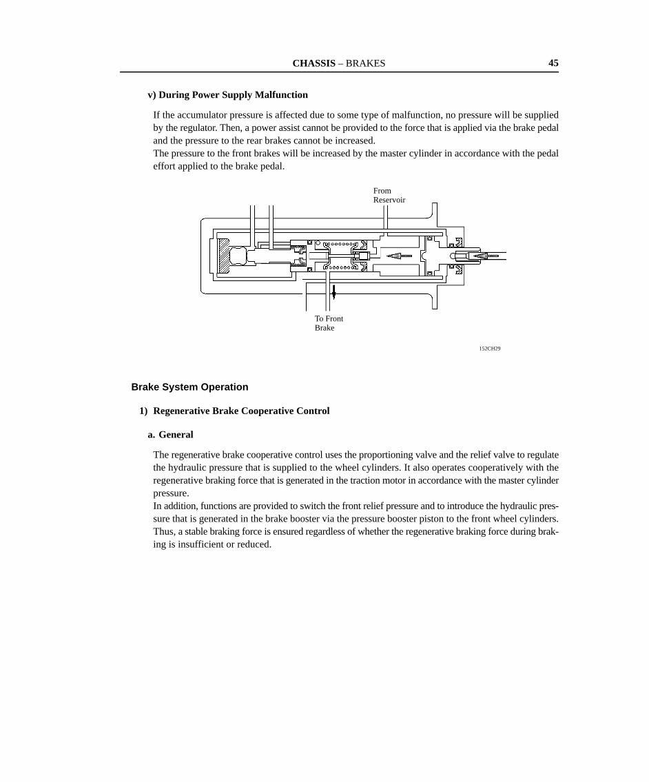
v) During Power Supply Malfunction
If the accumulator pressure is affected due to some type of malfunction, no pressure will be suppliedby the regulator. Then, a power assist cannot be provided to the force that is applied via the brake pedaland the pressure to the rear brakes cannot be increased.The pressure to the front brakes will be increased by the master cylinder in accordance with the pedaleffort applied to the brake pedal.
Brake System Operation
1) Regenerative Brake Cooperative Control
a. General
The regenerative brake cooperative control uses the proportioning valve and the relief valve to regulatethe hydraulic pressure that is supplied to the wheel cylinders. It also operates cooperatively with theregenerative braking force that is generated in the traction motor in accordance with the master cylinderpressure.In addition, functions are provided to switch the front relief pressure and to introduce the hydraulic pres-sure that is generated in the brake booster via the pressure booster piston to the front wheel cylinders.Thus, a stable braking force is ensured regardless of whether the regenerative braking force during brak-ing is insufficient or reduced.
CHASSIS – BRAKES
153CH16153CH25
�
BrakingForce
1.96 m/s2
(0.2 G)
Master Cylinder Pressure�
Regenerative Braking Force
Rear Hydraulic Braking Force
Front Hydraulic Braking Force
Without RegenerativeBrake CooperativeControl
�
WheelCylinder Pressure
RegenerativeBrakeCooperativeControl
Master Cylinder Pressure�
46
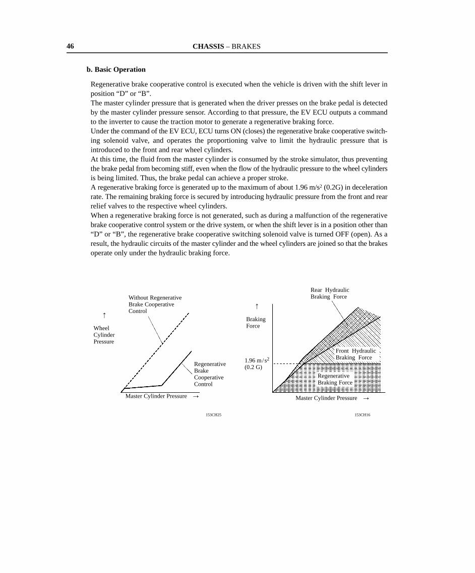
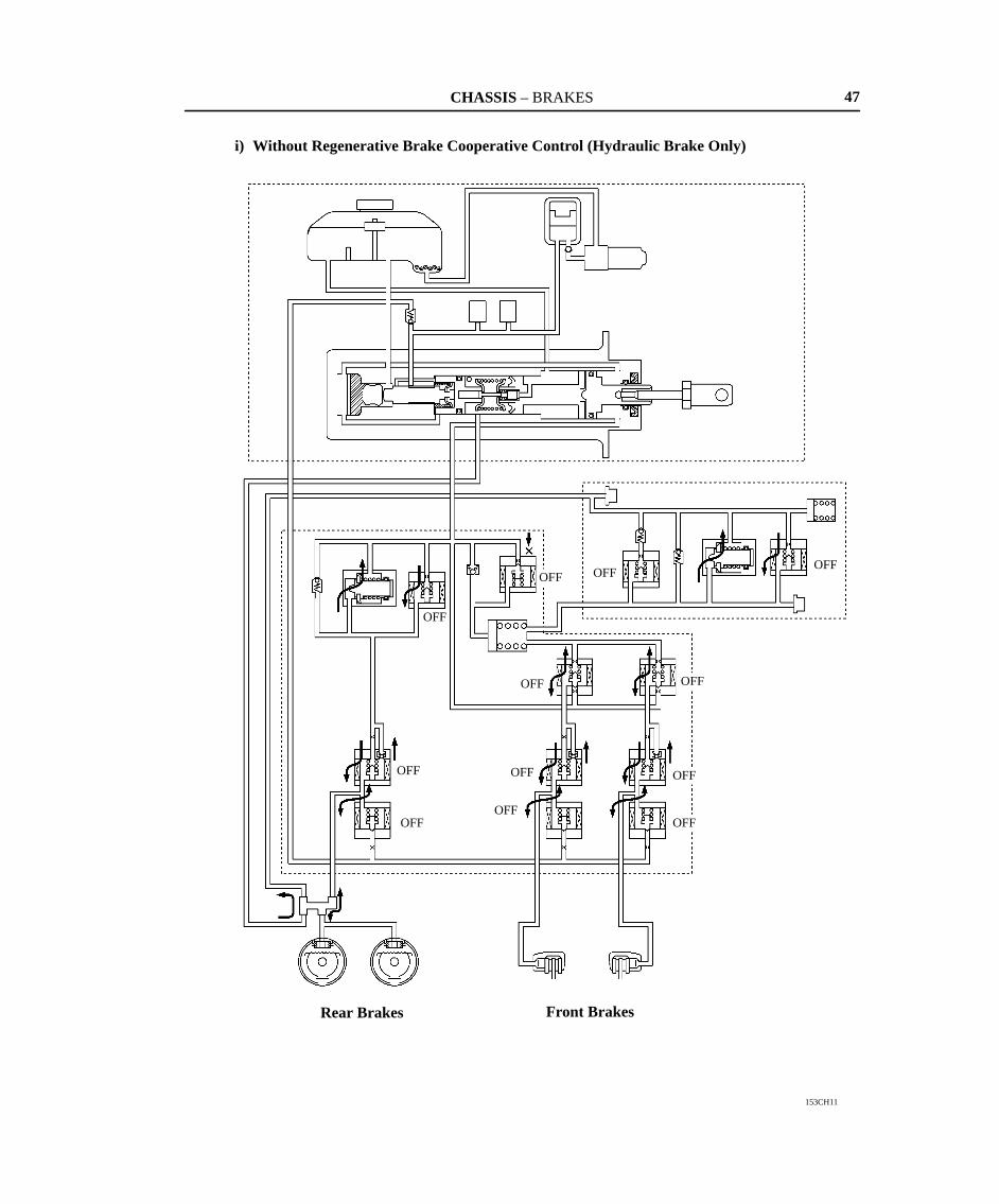
b. Basic Operation
Regenerative brake cooperative control is executed when the vehicle is driven with the shift lever inposition “D” or “B”.The master cylinder pressure that is generated when the driver presses on the brake pedal is detectedby the master cylinder pressure sensor. According to that pressure, the EV ECU outputs a commandto the inverter to cause the traction motor to generate a regenerative braking force.Under the command of the EV ECU, ECU turns ON (closes) the regenerative brake cooperative switch-ing solenoid valve, and operates the proportioning valve to limit the hydraulic pressure that isintroduced to the front and rear wheel cylinders.At this time, the fluid from the master cylinder is consumed by the stroke simulator, thus preventingthe brake pedal from becoming stiff, even when the flow of the hydraulic pressure to the wheel cylindersis being limited. Thus, the brake pedal can achieve a proper stroke.A regenerative braking force is generated up to the maximum of about 1.96 m/s2 (0.2G) in decelerationrate. The remaining braking force is secured by introducing hydraulic pressure from the front and rearrelief valves to the respective wheel cylinders.When a regenerative braking force is not generated, such as during a malfunction of the regenerativebrake cooperative control system or the drive system, or when the shift lever is in a position other than“D” or “B”, the regenerative brake cooperative switching solenoid valve is turned OFF (open). As aresult, the hydraulic circuits of the master cylinder and the wheel cylinders are joined so that the brakesoperate only under the hydraulic braking force.
CHASSIS – BRAKES
153CH11
OFF
OFF
OFF
OFF
OFFOFF
OFF
OFFOFF
OFFOFFOFF
Rear Brakes Front Brakes
47
i) Without Regenerative Brake Cooperative Control (Hydraulic Brake Only)
CHASSIS – BRAKES
153CH12
Regenerative Brake CooperativeSwitching Solenoid Valve
Relief Valve
P Valve ON
OFF
Relief Valve (For High Pressure)
Stroke Simulator
ONON
P Valve
Regenerative BrakeCooperative SwitchingSolenoid ValveOFF
OFF
OFFOFF
OFFOFF
OFF
Rear Brakes Front Brakes
OFF
48
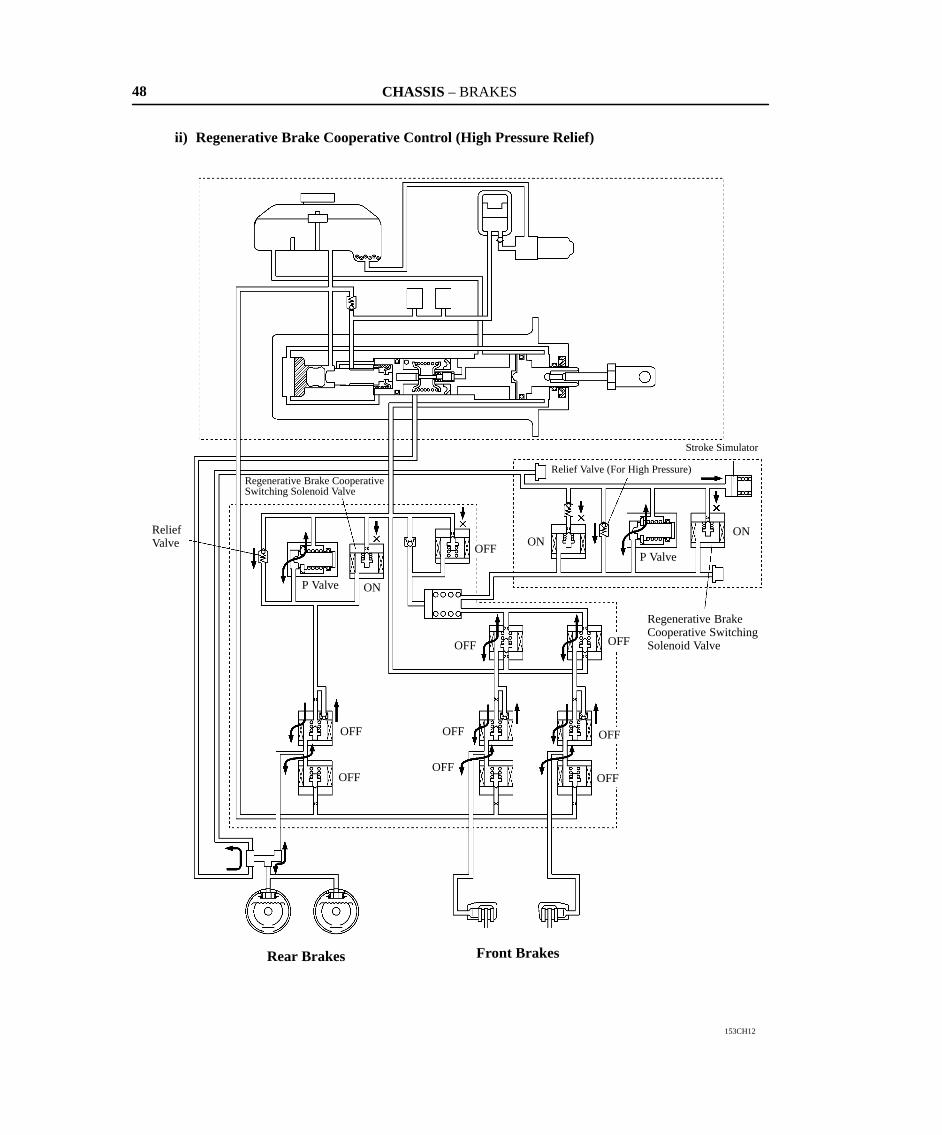
ii) Regenerative Brake Cooperative Control (High Pressure Relief)

CHASSIS – BRAKES
153CH13
Relief Valve (For Low Pressure)
OFF
OFF
OFF
OFF
OFF
OFF
OFF
OFF
ON
Relief Pressure Switching Solenoid Valve
OFFOFF
ON
Rear Brakes Front Brakes
49
iii) Regenerative Brake Cooperative Control (Low Pressure Relief)
CHASSIS – BRAKES
153CH17
: Regions in which the maximum regenerative braking force becomes reduced or deficient
�
Regenerative Braking Force
Vehicle Speed �
50
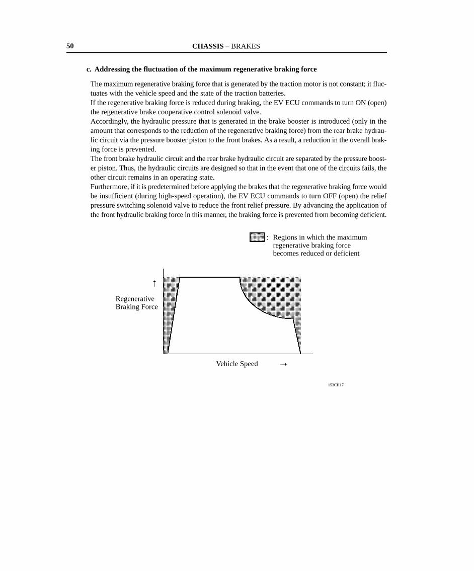
c. Addressing the fluctuation of the maximum regenerative braking force
The maximum regenerative braking force that is generated by the traction motor is not constant; it fluc-tuates with the vehicle speed and the state of the traction batteries.If the regenerative braking force is reduced during braking, the EV ECU commands to turn ON (open)the regenerative brake cooperative control solenoid valve.Accordingly, the hydraulic pressure that is generated in the brake booster is introduced (only in theamount that corresponds to the reduction of the regenerative braking force) from the rear brake hydrau-lic circuit via the pressure booster piston to the front brakes. As a result, a reduction in the overall brak-ing force is prevented.The front brake hydraulic circuit and the rear brake hydraulic circuit are separated by the pressure boost-er piston. Thus, the hydraulic circuits are designed so that in the event that one of the circuits fails, theother circuit remains in an operating state.Furthermore, if it is predetermined before applying the brakes that the regenerative braking force wouldbe insufficient (during high-speed operation), the EV ECU commands to turn OFF (open) the reliefpressure switching solenoid valve to reduce the front relief pressure. By advancing the application ofthe front hydraulic braking force in this manner, the braking force is prevented from becoming deficient.

CHASSIS – BRAKES
153CH14
Regenerative Brake Cooperative Control Solenoid Valve
ON ONON
Pressure Booster Piston OFF
OFF
OFF
OFF
OFF OFF
OFF
Relief PressureSwitching SolenoidValve
Rear Brakes Front Brakes
OFF
ON
51
� High Relief Pressure
CHASSIS – BRAKES
153CH15
OFF
OFF
OFF
OFFON
ON
ONOFF
OFF
ON
ONPressure Reduction Mode
PressureHoldingMode
ABS Switching Solenoid Valves
ABS Control Solenoid Valves
PressureIncreaseMode
Front BrakeRear Brake
ON
52
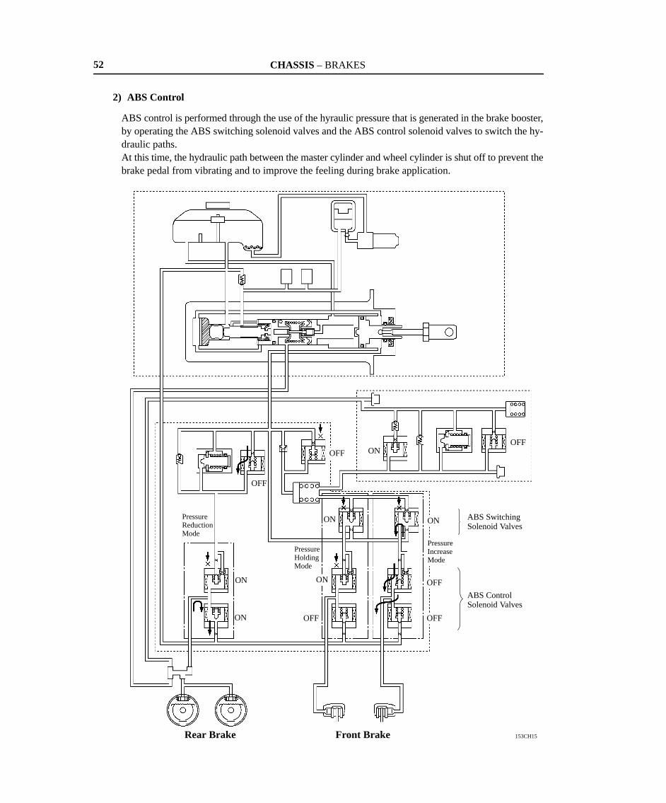
2) ABS Control
ABS control is performed through the use of the hyraulic pressure that is generated in the brake booster,by operating the ABS switching solenoid valves and the ABS control solenoid valves to switch the hy-draulic paths.At this time, the hydraulic path between the master cylinder and wheel cylinder is shut off to prevent thebrake pedal from vibrating and to improve the feeling during brake application.
CHASSIS – BRAKES 53
ABS & Hydraulic Brake Booster ECU
1) Initial Check
After the motor switch is turned on, the ABS & hydraulic brake booster ECU performs an initial check.The function of each solenoid valve in the actuator is checked in order.
2) Self-Diagnosis
If the ABS & hydraulic brake booster ECU detects a malfunction in the brake system, the ABS warninglight and brake warning light will light up and alert the driver that a malfunction has occured. The ECUwill also store the codes of malfunctions. See the 2002 RAV4 EV Repair Manual (Pub. No. RM892U)for the diagnostic code check method, diagnostic code and diagnostic code clearance.
3) Speed Sensor Check Function
The ABS & hydraulic brake booster ECU has a speed sensor check function. The output voltage leveland output voltage fluctuation of the speed sensor can thus be checked. The results of each check areindicated by the ABS warning light blinking the appropriate code. For the check procedure and diagnos-tic code of speed sensor check function, see the 2002 RAV4 EV Repair Manual (Pub. No. RM892U).
NOTE: The ABS does not function when the ECU is in the speed sensor check function.
4) ABS Warning Light Check Function
The ABS warning light turns on for about 3 seconds after the motor switch is turned on to check the cir-cuit.
5) Fail-Safe
If the ABS & hydraulic brake booster ECU detects a malfunction in the brake system, the ECU cuts offits current to the actuators. As a result, the brake system operates in the same way as in a vehicle withoutABS.
CHASSIS – BRAKES54
�TIRE PRESSURE WARNING SYSTEM
1. General
� This system does not use a pressure sensor to detect a reduction in the tire inflation pressure. Instead, ituses the fluctuation of the ABS wheel speed signal that varies with the ground surface input while the ve-hicle is being driven, from which the torsional spring constant is estimated. The reduction in the springconstant is then rendered as the reduction in the tires’ inflation pressure.
� If the vehicle is driven with a low tire pressure that could impede driving, this system illuminates the tirepressure warning light in the combination meter to alert the driver of the reduction in the tire inflation pres-sure.
� This system is provided merely as a means of helping the driver to inspect the tire pressure, which is oneof the do-it-yourself maintenance items.
� This system can reduce the effects of reduced tire inflation pressure as described below.
� Poor electrical power consumption rate due to the increase in rolling resistance.
� Abnormal wear of the tires due to an uneven distribution of tire-to-ground contact.
� Poor stability and controllability due to the reduction in tire performance.
� Possibility of the tire becoming separated from its rim due to the reduction in the bead securing force.
� Possibility of damaging the tire due to the reduction in tire rigidity.
NOTES: � This system cannot detect the tire pressure when the vehicle is stationary because the tire pressuredetection is based on the rotating condition of the tires when the vehicle is in motion.
� If the warning light turns ON, the tire pressure must be checked and adjusted.
� This system may not operate properly under the conditions given below.
� The tires of a size that is not specified are used, or different sizes and types of tires are com-bined.
� The extent of the wear of one tire is considerably different from that of other tires.
� A temporary use of spare tire, snow tire, or tire chain.
� The tires are inflated excessively higher than the specified air pressure or the tire pressure dropssuddenly due to a flat tire that is caused during driving.
� The vehicle is driven on an extremely rough surface or on a slippery surface such as an icy road.
CHASSIS – BRAKES
153CH26
153CH33
153CH34
Reduced tire inflationpressure
�TorsionalSpringConstant
Tire Inflation Pressure �
Tire inflation pressurejudged to be reduced
Reduced tire torsionalspring constant
Tire torsional springconstant judged to bereduced
Tire Vibration Model
Rim
Change in tire resonance frequency
Wheel Speed Amplitude
Reduced
Detection of changesin tire resonance frequency
Frequency
ABS & Hydraulic Brake Booster ECU
55
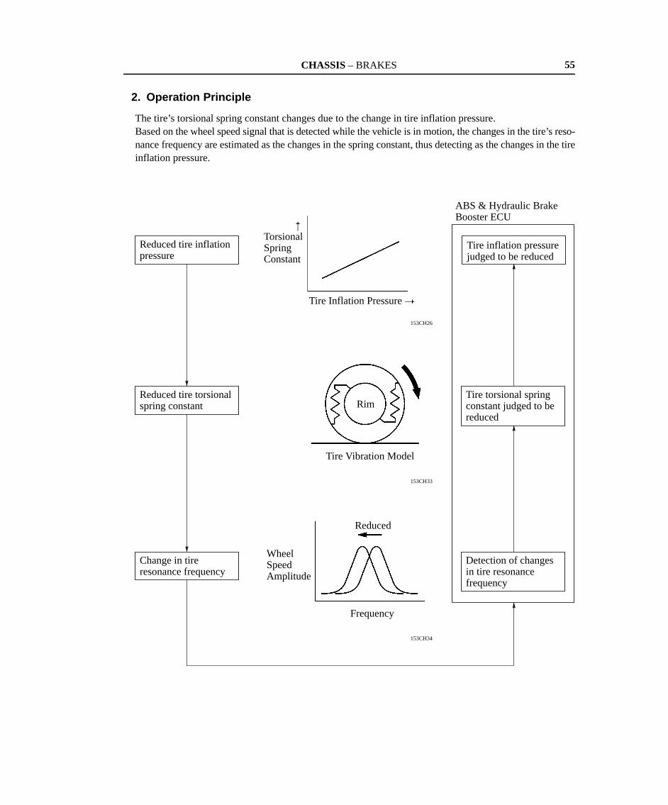
2. Operation Principle
The tire’s torsional spring constant changes due to the change in tire inflation pressure.Based on the wheel speed signal that is detected while the vehicle is in motion, the changes in the tire’s reso-nance frequency are estimated as the changes in the spring constant, thus detecting as the changes in the tireinflation pressure.
CHASSIS – BRAKES
153CH27
Speed Sensors
ABS & Hydraulic Brake Booster ECU
Sensor’s raw waveform signal
Wheel speed signal forming processing IC
� Noises other than tire resonance are removed.� Changes in tire torsional spring constant are
estimated.� Pressure reduction judgement processing
Formed pulse signal
Tire Pressure Warning Light
ABS CPU (Tire Pressure Warning Function)
153CH36
Tire Pressure Warning Light
Set Switch
SpeedSensors
ABS & HydraulicBrake Booster ECU
Stop Light Switch
Speed Sensors
OutsideTemperatureSensor
56
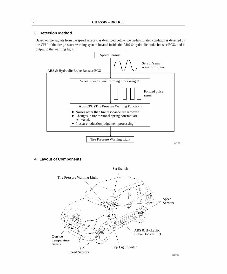
3. Detection Method
Based on the signals from the speed sensors, as described below, the under-inflated condition is detected bythe CPU of the tire pressure warning system located inside the ABS & hydraulic brake booster ECU, and isoutput to the warning light.
4. Layout of Components

CHASSIS – BRAKES 57
5. Function of Components
Components Function
ABS & HydraulicBrake Booster ECU
Based on the wheel speed signals and etc., it detects the tire inflation pressureand sends signal to the tire pressure warning light.
Speed Sensors Detect the wheel speed of each wheel.
Tire Pressure WarningLight
Lights up to alert the driver when the ECU detects the tire inflation pressureand the malfunction in the tire pressure warning system.
Outside TemperatureSensor
Detects temperature data for correcting the estimated value of the tireinflation pressure.
Stop Light SwitchSends a signal to the ECU to prohibit the estimation of the tire inflationpressure during braking.
Set Switch Used for inspecting the tire pressure warning system.


![[PPT]Regenerative Braking Systems and their functions · Web viewHow Does Regenerative Braking Work? Regular brakes waste large amounts of useable energy6 Regenerative Braking systems](https://static.fdocuments.us/doc/165x107/5ae8634b7f8b9aee078f7805/pptregenerative-braking-systems-and-their-functions-viewhow-does-regenerative.jpg)

![REGENERATIVE BRAKING SYSTEM IN ELECTRIC VEHICLES · REGENERATIVE BRAKING SYSTEM IN ELECTRIC VEHICLES ... REGENERATIVE BRAKING SYSTEM ... Regenerative action during braking[9].](https://static.fdocuments.us/doc/165x107/5adccef67f8b9a1a088c7cf0/regenerative-braking-system-in-electric-vehicles-braking-system-in-electric-vehicles.jpg)


