Brake System Fundamentals - BAJA Tutor · PDF fileBRAKE SYSTEM FUNDAMENTALS ... Front Axle...
62
BRAKE SYSTEM FUNDAMENTALS KARAN BHARDIYA ASSISTANT MANAGER -R&D ENDURANCE TECHNOLOGIES PVT.LTD. DISC BRAKES
Transcript of Brake System Fundamentals - BAJA Tutor · PDF fileBRAKE SYSTEM FUNDAMENTALS ... Front Axle...
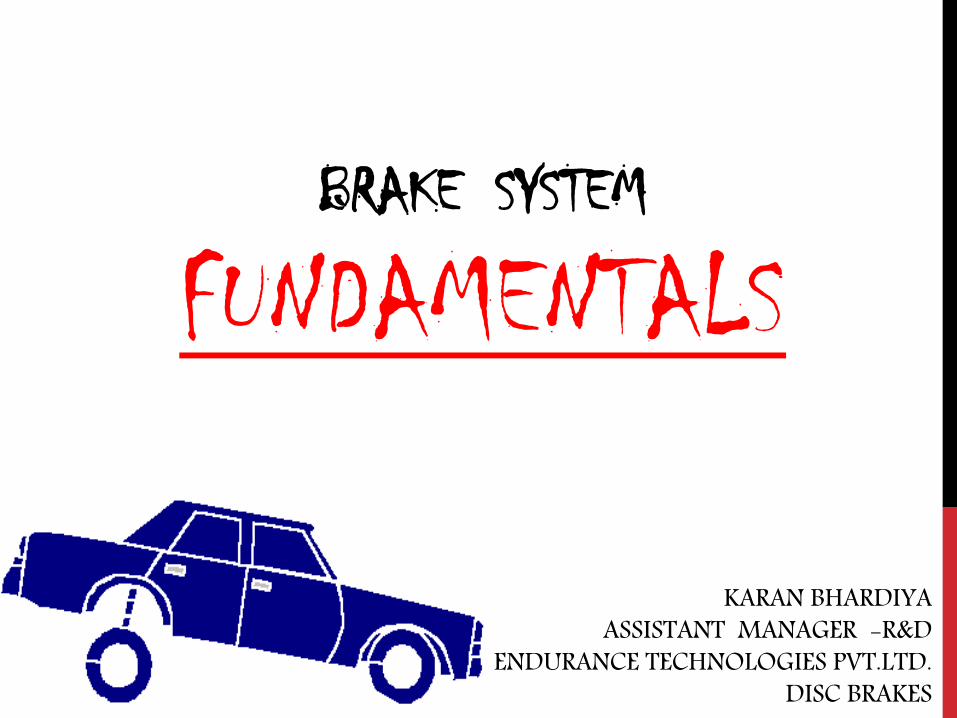
BRAKE SYSTEM
FUNDAMENTALS
KARAN BHARDIYA ASSISTANT MANAGER -R&D
ENDURANCE TECHNOLOGIES PVT.LTD. DISC BRAKES

AUTOMOTIVE BRAKING SYSTEMS
How brakes manufacturing industry is different then rest of the automotive industries ????

HOW IT WORKS
Friction develops heat which absorbs kinetic energy of the car
3

PURPOSE OF BRAKING SYSTEM
Stop the vehicle by converting the kinetic energy of the vehicle to heat energy.
Heat energy is created in the brakes by friction.
Friction is created between a moving and a non-moving surface at each wheel to
generate the heat.
Disc and drum brakes are the most common type of braking systems used.
4

FACTORS EFFECTING BRAKING*
Number of wheels braking.
Weight of vehicle.
Type of friction material.
Surface area of friction material.
Size or discs or drums
Tire traction.
Road surface.
Load transfer.
Incline or decline of road. (gravity)
Engine braking.
Pressure applied
5

TYPES OF BRAKING SYSTEMS
Service brakes. It’s the primary braking system using a the pedal connected to a hydraulic system causing it to operate.
Parking brakes. It’s mechanically applied by a lever or pedal.
6

TYPICAL SYSTEM (NO ABS)

TYPICAL LAYOUT OF SYSTEM (WITH ABS)

COMPONENTS

ELEMENTS OF DISC BRAKE
There are major four elements of brake disc
1. Master Cylinder – usually accessible by user & is a actuating device.
2. Brake Caliper - is the end part of effort transmission in brakes which retards the motion of two wheeler
3. Hose – is for transmission of Oil from Master Cylinder to Brake caliper
4. Brake Disc – mounted on wheel & is major part in braking action & absorbing the braking energy .

WORKING OF MASTER CYLINDER Principle:
Master cylinder works on principle of pumping of incompressible fluids, in which the pressure is applied on Brake Fluid/oil which then transferred to caliper for actuation of brake pads.

The “feed aperture “( 0.5 mm Micro hole ) and “compensation hole” are
open and connect the “pressure chamber” and “compensation enclosure”
to reservoir.
A small quantity of fluid returns from pressure chamber to reservoir before
primary seal completely blocks the feed aperture
Once this condition is achieved, any force exerted on the lever is
transformed into pressure in the brake circuit.
WORKING OF MASTER CYLINDER

When the brake lever is released, the piston is pressed back quickly by
the return spring to its own position.
Due to this, a vacuum is generated in the pressure chamber and the
fluid in the compensation chamber flows to pressure chamber past the
primary seal, due to its flexible lip edges which allow the brake fluid to
pass to pressure chamber.

TANDEM MASTER CYLINDER ASSEMBLY

TANDEM MASTER CYLINDER ASSEMBLY

MASTER CYLINDER ASSEMBLY
NEVER ALLOW MINERAL OIL TO
COME IN CONTACT WITH SEALS OR
OTHER RUBBER PARTS OF DISC
BRAKE, SINCE IT WILL CAUSE
DAMAGE TO THESE PARTS
FREE PLAY AT THE END OF THE
LEVER IS PROVIDED TO ENSURE
THAT IN THE FREE CONDITION,
THE PISTON DOES NOT REMAIN
IN THE PUSHED CONDITION.
THIS ENSURES THAT THERE IS
NO PRESSURE IN THE SYSTEM
WHEN THE BRAKE IS NOT
APPLIED.

WORKING OF CALIPER Principle
Caliper assembly converts the hydraulic pressure generated in the master
cylinder into gripping force on the rotating brake disc & retards the rotation
of disc .

DISC BRAKE SYSTEM Hydraulic pressure transmitted
via brake lines and hoses to
piston(s) at each brake caliper.
Pistons operate on friction pads
to provide clamping force
Rotors are free to rotate due to
wheel bearings and ubs that
contain them
Hub can be part of brake rotor or
separate assembly that the rotor
slips over and is bolted to by the
lug nuts
The hub and hubless rotors.

WORKING OF HYDRAULIC BRAKE CALIPER (SINGLE ACTING FLOATING TYPE)
In the brake released condition, the brake fluid inside the caliper is at
atmospheric pressure and the disc rotates freely as the pads do not press
against it.
When the brake lever is operated, the
pressure generated in the hydraulic circuit
acts on the caliper pistons. The caliper
pistons in turn push the friction pad on
the side of the caliper body against the
rotating disc.

The friction pad on the other side
of the disc also presses against
the disc due to reaction force on
caliper body. Thus both the
friction pads press against the
disc, thereby generating
braking torque & retards the
wheel motion .
WORKING OF HYDRAULIC BRAKE CALIPER (SINGLE ACTING FLOATING TYPE) …CONTD.

DISC BRAKE SYSTEM
Square cut O-ring. A. Square cut O-ring during brake application.
B. Square cut O-ring during brake release.

WORKING OF CALIPER AT GLANCE

DISC BRAKE SYSTEM
The brake caliper assembly is normally Bolted to vehicle axle housing (steering knuckle)
Caliper mounting methods.

DISC BRAKE SYSTEM
Two types of calipers: fixed and sliding/floating

DISC BRAKE SYSTEM
FixedType Brake System
Applies two pistons to opposite sides of rotor
Caliper stays stationary
Disc Brakes require higher hydraulic pressure
DISC BRAKE SYSTEM
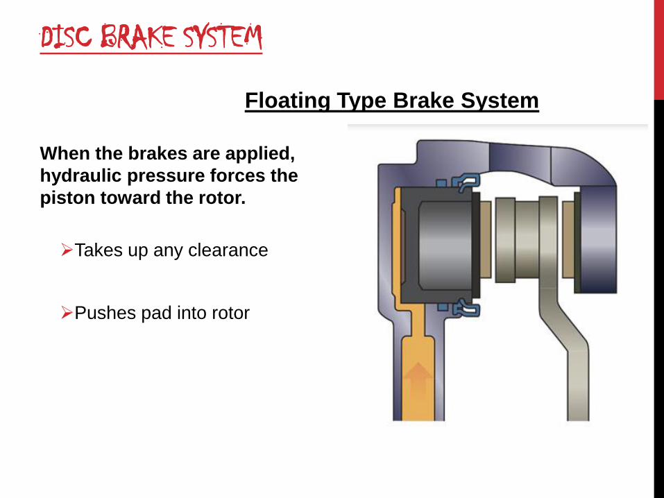
When the brakes are applied,
hydraulic pressure forces the
piston toward the rotor.
Takes up any clearance
Pushes pad into rotor brake
pads, applying brakes.
Sliding/floating caliper application.
Floating Type Brake System

DISC BRAKE SYSTEM
tSquare cut O-ring seals piston in disc brake calipers.
Compressed between piston and caliper housing
Keeps high-pressure brake fluid from leaking
Prevents air from being drawn into system
O-ring and O-ring cut to show square section. B. Square cut O-ring
groove in caliper.

DISC BRAKE SYSTEM
Although the phenolic pistons
themselves do not corrode, the
cast iron bore of the caliper
does corrode and rust
Can cause a phenolic piston to
seize in the bore
Phenolic pistons transfer heat slower than steel pistons
Helps prevent boiling of the brake fluid

APPLY SILICONE
GREASE ON
SECONDARY PIN
SLIDING SURFACE
APPLY LOCTITE TO
SECONDARY PIN
THREADS BEFORE ASSY
NEVER ALLOW MINERAL OIL TO
COME IN CONTACT WITH SEALS OR
OTHER RUBBER PARTS OF DISC
BRAKE, SINCE IT WILL CAUSE
DAMAGE TO THESE PARTS
DISC BRAKE SYSTEM
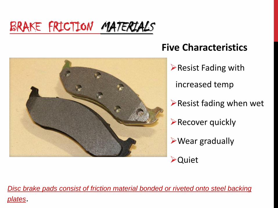
BRAKE FRICTION MATERIALS Five Characteristics
Resist Fading with
increased temp
Resist fading when wet
Recover quickly
Wear gradually
Quiet
Disc brake pads consist of friction material bonded or riveted onto steel backing
plates.

LINING MATERIAL
Non-metallic
Made from synthetic fibers (used to be asbestos)
Semi-metallic
Made from iron and synthetic fibers
More fade resistant - harder pad
More prone to squealing
Full-metallic
Made from sintered metals
Very hard pad

DISC BRAKE PADS AND FRICTION MATERIALS
Composition of friction material affects brake operation
Materials that provide good braking with low pedal pressures tend to lose efficiency when hot
Wear out quicker
Materials that maintain stable friction coefficient over a wide temperature range
Generally require higher pedal pressures
Tend to put added wear on disc brake rotor

DISC BRAKE SYSTEM
•Advantages
Greater amounts of heat to atmosphere
Cooling more rapid
Rotors scrape off water more efficiently
Self-adjusting
Don’t need periodic maintenance
Easier to service

DISC BRAKE SYSTEM
Disadvantages
Prone to noise (squeals and squeaks)
Rotors warp easier
Not self-energizing
Hard to use as parking brakes

BRAKE PLUMBING
Rigid steel brake lines are
double wall
Flexible hoses connect
rigid lines on vehicle to
each wheel
Transmits hydraulic fluid
to each wheel
AUTO RICKSHAW’S FRONT TUBE IS BEST FOR COUPLING
36
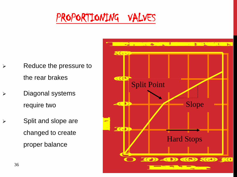
PROPORTIONING VALVES
TYPICAL PROP VALVE PERFORMANCE CURVE
02004006008001,0000
200
400
600
800
Front Brake Pressure
Rear Brake PressureSplit Point
Slope
Hard Stops
Reduce the pressure to
the rear brakes
Diagonal systems
require two
Split and slope are
changed to create
proper balance

DRUM BRAKE SYSTEM
F = ma

WHEEL CYLINDER
Wheel cylinder or caliper pistons
are “slave cylinders”
Change hydraulic pressure back
into mechanical force
Can use one or two cylinders at
each wheel

POWER ASSIST INCREASES FORCE OF DRIVER’S FOOT

CABLE PARKING BRAKE
Parking or “Emergency” Brake

PARKING BRAKE SYSTEMS
Foot or Hand Brake
Are cable controlled
• Several Styles • As shown
• Drum in hat
• Driveline

BRAKE SYSTEM ENERGY

BRAKE SYSTEM PRINCIPLES
Kinetic Energy
Mass
Weight
Speed
Inertia and Momentum

FRICTION PRINCIPLES
Kinetic and Static Friction
Friction and Pressure
Friction and Surface Area
Coefficient of Friction
Brake Fade

BRAKING DYNAMICS
Weight Transfer
Weight Distribution
Braking Power
Friction Efficiency
Brake to Wheel
Wheel to Road Surface
Traction Efficiency
Skidding

HYDRAULIC PRINCIPLES
Fluids cannot be compressed
Fluids can transmit Movement
Acts “Like a steel rod” in a closed container
Master cylinder transmits fluid to wheel cylinder or caliper piston
bore.
Fluids can transmit and increase force
The area of the piston is determined by using the formula
3.14 X R2

HYDRAULIC PRESSURE IS DISTRIBUTED EQUALLY IN ALL DIRECTIONS

THE APPLIED FORCE CAN BE CHANGED BY CHANGING THE PISTON SIZE.
F = PXA
F A

ADVANTAGE BY HYDRAULICS
F = ma & F = pa

50
BRAKE PEDAL DESIGN
Driver Input
Output to master cylinder
100 N and 144 mm
400 N and 36 mm 4:1 Nominal
Pedal Ratio
First Mechanical Advantage is Driver’s foot
Length of Lever determines force applied
Uses Fulcrum
Pedal Ratio

STEPS TO BE FOLLOWED DURING DESIGNING
Packaging constraints
Avaibility in the market
Design requirements
BR
AK
E FO
RC
E A
T R
EAR
BRAKE FORCE AT FRONT
BRAKE FORCE DISTRIBUTION DIAGRAM
UNLADEN CONDITION
LADEN CONDITION

PACKAGING CONSTRAINTS

VEHICLE DATA REQUIRED FOR CALCULATIONS
GVW -Laden
Front Axle weight (Kg) if provided 125.92
Calculated 125.92
Rear Axle weight (Kg) 160.08
160.08
Wheel base "e" (m) 1.49
GVW (Kg) 286.00
C.G. "h" (m) 0.545
Mechanical efficiency 0.9
Hydraulic efficiency 0.9
front
Pedal ratio 4.5
Caliper Piston dia (cm)
Number Of Pistons 2
Area (cm2) 12
Effective radius (m) 0.107
Master dia (cm) 1.92
Master Piston Area(cm2) 1.13
Mue 0.37
Static Rolling radius (m) 0.291
Dynamic Rolling radius (m) 0.291

FINDING THE C.G OF THE VEHICLE ??

IS 12793 : 1989 & ONLINE STUFFS

FIND THE LOAD TRANSFER FROM THE VEHCILE DATA
Dynamic load transfer in laden condition @--- G condition :
= {GVWx --Gx Height of C.G from ground in laden condition}
wheel base
Dynamic load transfer in laden condition on front Axle Rf @ ---G conditions:
=Front axle weight in laden condition +{ Dynamic load transfer in laden condition @ ---G condition}
Braking force in laden condition on front Axle Rf @---G conditions:
= --G x{Dynamic load transfer in laden condition on front axle @---- G in laden condition}
The braking torque on front axle @ --- G in laden condition :
= braking force on front axle @---G in laded condition x{front tyre dynamic rolling radius }
STEP :1
STEP :2
STEP :3
STEP :4

FIND THE LOAD TRANSFER FROM THE VEHCILE DATA
Dynamic load transfer in laden condition on Rear Axle Rr @--- G conditions:
RAW—{dynamic load transfer in unladen condition @0.6G condition}
}
Thus the braking force at Rear @---G in laden condition
=--Gx{load transfer at Rear axle @--G in unladen condition}
The braking torque on Rear axle @---G in unladen condition :
= braking force on Rear axle @---G in unladen condition x{Rear tyre dynamic rolling radius }
This is the minimum requirements of the vehicle as per wheight and C.G of the vehicle.
STEP :5
STEP :6
STEP :7
1309064
Sticky Note
braking force per tyre = braking force at front or rear /2

DIMENSIONS OF CALIPERS TO SUIT THE DESIRED CONFIGARATIONS OF THE VEHICLE:
Diameter of caliper piston= ----mm
Area of caliper piston = ----- mm2
Coefficient of friction of the pad (mue) = 0.37
Disc outer diameter = 200mm ( based on market survey and packaging )
Effective radius of the disc is 100-13 ( radius of the disc - half the width of the
brake pad +1mm) =87mm
Dynamic tire radius of the front wheel (r)= ------ mm

OUT PUT OF THE DESIGN : @ 0.6G & 1G MAX LINE PRESSURE = PEDAL EFFORT X PEDAL RATIO X 0.9 ( hydraulic losses)
M.C AREA
BRAKING FORCE FRONT = (LINE PRESSURE X CALIPER AREA X EFFECTIVE RADUIS X MUE X 2 )
FRONT DYNAMIC ROLLING RADIUS
BRAKING TORQUE= BRAKING FORCE FRONT X FRONT DYNAMIC ROLLING RADIUS
UNLADEN WHEEL UNLOCKED DECELERATION = BRAKING FORCE FRONT TARGET IS 0.6G
K.V.W
LADEN WHEEL UNLOCKED DECELERATION = BRAKING FORCE FRONT TARGET IS 0.6G
G.V.W

CONCLUSION :
Finally the results of BRAKING FORCE FRONT = (LINE PRESSURE X CALIPER AREA X EFFECTIVE RADUIS X MUE X 2 )
FRONT DYNAMIC ROLLING RADIUS
shall be greater then
>
Braking force in laden condition on front Axle Rf @---G conditions:
= --G x{Dynamic load transfer in laden condition on front axle @---- G in laden condition}

SUGGESTIONS :
MASTER CYLINDER –. GO AHEAD WITH T.M.C OF REGULAR SIZE 19.2 MM BORE
BUNDY TUBES- Metallic tubes are easily available in the market cut & braze it as per
requirements
BRAKE CALIPER – Most of the calipers available in the market are 28 x2 diameter use it for
rear Use 30 dia single piston caliper @ front
Hose – Bajaj Auto’s front hose should we chosen. Easily mates with the Bundy tube end.
BRAKE DISC – try to fit the Max possible dia of the disc based on the packaging constraints

THANK YOU
A designer knows he has achieved perfection not when there is nothing left to add, but when there is nothing more to take away”