BRAKE FRICTION MATERIALS - NASA · BRAKE FRICTION MATERIALS: A MARKET SURVEY By: ... STANFORD...
86
(NASA-C_- I_9028) A MARKET SURVEY 83 p BRAKE FRICTION MATERIALS: A MARKET SURVEY By: James P. Wilhelm Andrew V. Loomis Conducted for the TECHNOLOGY UTI LIZATI__E NATIONAL AERONAUTICS AND SPACE ADMINISTRATION BHAKE FPICTION MATERIALS: (Stanford _esearch Inst.) N77-70130 Unclas 00/98 15q25 REPRODUCED BY NATIONAL TECHNICt_L INFORMATION SERVICE U.S. DEPARTMENTOF COMMERCE SPRINGFIELD,VA. 2216] STANFORD RESEARCH INSTITUTE Menlo Park, California 94025 • U.S.A. https://ntrs.nasa.gov/search.jsp?R=19770068911 2018-06-17T14:42:07+00:00Z
Transcript of BRAKE FRICTION MATERIALS - NASA · BRAKE FRICTION MATERIALS: A MARKET SURVEY By: ... STANFORD...

(NASA-C_- I_9028)
A MARKET SURVEY
83 p
BRAKE FRICTION MATERIALS:
A MARKET SURVEY
By: James P. Wilhelm
Andrew V. Loomis
Conducted for the
TECHNOLOGY UTI LIZATI__E
NATIONAL AERONAUTICS AND
SPACE ADMINISTRATION
BHAKE FPICTION MATERIALS:
(Stanford _esearch Inst.)
N77-70130
Unclas
00/98 15q25
REPRODUCED BY
NATIONAL TECHNICt_L
INFORMATION SERVICEU.S. DEPARTMENTOFCOMMERCE
SPRINGFIELD,VA. 2216]
STANFORD RESEARCH INSTITUTEMenlo Park, California 94025 • U.S.A.
https://ntrs.nasa.gov/search.jsp?R=19770068911 2018-06-17T14:42:07+00:00Z


August 1975
BRAKE FRICTION MATERIALS: A MARKET SURVEY
By: JAMES P. WILHELM
ANDREW V. LOOMIS
STANFORD RESEARCH INSTITUTE
MENLO PARK, CALIFORNIA 94025
Conducted for the:
TECHNOLOGY UTILIZATION OFFICE
NATIONAL AERONAUTICS AND SPACE ADMINISTRATION
WASHINGTON, D.C.


EXECUTIVE SUMMARY
A composition material developed by National Aeronautics and
Space Administration (NASA_ may be useful as an improved vehicle
brake friction material. To assist NASA in identifying a potential
market for this material, the SRI Technology Applications Team
has conducted a survey of the market for vehicle brake friction
materials in the United States.
The purpose of this market survey is to outline the technical
and economic requirements that a candidate composition friction material
must meet before it can be considered a viable product. In addition,
we have reviewed the properties of composition brake friction materials
currently on the market to identify those properties that, if improved,
would be a useful advance to the product. Consequently, any new
material that possesses any of these improvements may have a competitive
advantage over currently available materials.
The brake friction material developed by scientists at NASA's
Ames Research Center exhibits an essentially constant coefficient of
0friction with temperatures ranging as high as 650 F and an average
coefficient of friction of approximately 0.34. A comparison of the
change in coefficient of friction versus temperature for the NASA
material and conventional brake lining materials demonstrates the
o
superiority of the NASA material at temperatures greater than 400 F.
At these higher operating temperatures the NASA material's coefficient
of friction actually increases while that of conventional brake linings
decreases markedly. Wear improvement at elevated temperatures has
ii

also been noted.
Considering the market, based on the data gathered during the course
of this survey, the bus-brake market appears to have the highest potential
for the successful entry of a new brake friction material. Such a material
would need to exhibit the following improvementsover conventional linings:
• Reducednoise during braking
• Reducedfade, more stable coefficient of friction at
elevated temperatures.
Reducedlining wear
Reduceddrumwear
A Either comparable in price to conventional linings or exhibiting
no more than a 40%increase.
Market size is estimated at 750,000 to 800,000 pieces per year
(original equipment) and as high as 8.0-8.2 million pieces per year
(after-market). This represents a yearly market of $22-27 million.
Themarket chosen as the secondmost favorable for the penetration
of a new friction material is the heavy truck brake lining market.
Rising labor costs and increased federal legislation have increased the
industry's awareness of its need for such newmaterials.
The original equipment market for truck linings in 1975 is estimated
to be approximately 8.0-8.5 million brake blocks at a market value of
$20-21.3 million. An additional 1.46 to 1.49 million pieces at a value
of $3.65 million to $3.75 million will be sold for use on new trailers
manufacturers in 1975.
The after-market for trucks and trailers is estimated at 9.50 to
10.25 million brake blocks at a value of $23.8 to $25.6 million.
Although a considerably more detailed study than was possible in
this survey is necessary to accurately determine the size of the market,
iii
Vehicle Type
it appears that improved brake friction materials are also needed in the
industrial equipment sector. This category includes equipment such as
overhead cranes, hoists and the like and represents an overall brake-
lining market value estimated at $80-100 million annually.
Other areas studied include passenger cars, light trucks, heavy
trucks and truck/trailers, rail cars and light aircraft. Estimates
of the current brake lining market for these sectors are given below:
VolumePieces/Market Year (000)
PassengerCarsPassengerCarsLight TrucksLight TrucksTrucksTrucksTrailersTrailersBusesBusesRail CarsLight Aircraft
Original EquipmentAfter-MarketOriginal EquipmentAfter-MarketOriginal EquipmentAfter-MarketOriginal EquipmentAfter-MarketOriginal EquipmentAfter-Market
72,000-73,000210,000-220,000
16,000-18,00022,000-24,0008,000-8,5004,000-4,2501,460-1,4905,500-6,000
750-8008,000-8,2003,290
600
Market entry into these sectors is strongly limited by lining cost
(i.e., a very strong technical advance over current materials would be
required to justify any additional lining cost). For this reason, and
our belief that the NASAmaterial does not exhibit these advances, we
do not anticipate market penetration in these areas.
In summary, it appears that the NASAAmesbrake friction material
will gain its easiest market entry in the bus, truck and industrial
equipment brake sectors. To insure this penetration the NASAmaterial,
once released, must exhibit a more stable coefficient of friction at
elevated stable temperatures than conventional materials, must show
somewear improvementover conventional materials and will have to be
at best cost competitive or at least, cost effective.iv
CONTENTS
I INTRODUCTION
II THE NASA FRICTION MATERIAL
III PASSENGER CARS AND LIGHT TRUCKS
A. Background
B. Product Requirements and Performance
C. Market
IV TRUCKS AND TRAILERS
A. Background
B. Product Requirements and Performance
C. Market
V BUSES
A. Background
B. Product Requirements and Performance
C. Market
VI AGRICULTURAL, CONSTRUCTION AND INDUSTRIAL
EQUIPMENT
A. Background
B. Product Requirements and Performance
C. Market
Vll RAIL CARS
A. Background
B. Product Requirements and Performance
C. Market
VIII AIRCRAFT
A. Background
B. Product Requirements and Performance
C. Market
6
7
i0
13
14
15
18
18
20
22
23
24
28
31
4O
48
49
51

IX BRAKELININGMANUFACTURINGPROCESSES
A. Dry ProcessB. Extruded ProcessesC. Wet Board ProcessesD. Sheeter ProcessesE. Sintered Metal ProcessF. WovenProcess
X BRAKELINING TESTING
A. DynamometerTestingB. Standard DynamometerTest ProceduresC. Motor Vehicle TestingD. Rail Car Brake Lining TestsE. Aircraft Brake Lining Tests
XI CONCLUSIONS
XII APPENDIX- LIST OFTERMS
535354555556
5762656667
69
73
vi

FIGURES
Comparison of NASA Developed Brake Lining
Composite with Conventional (Standard)
Materials
Comparison of Wear of NASA Developed Brake
Lining Composite with Conventional Brake
Lining
3 Composition Brake Shoe Adhesion (at Constant
Pressure) Compared to Wheel-to-Rail Adhesion
4 Variation of Coefficient of Friction with
Instantaneous Speed
5 Effect of Braking Ratio on Shoe Wear of a
Cobra Shoe
32
34
37
vii
TABLES
1 Brake Lining Manufacturers
2 Rail Vehicle Data
3 Estimated Rail Car Composition Brake Friction
Material Market
4 Common Sizes and Prices of Rail Car Brake
Shoes and Pads
26
3O
42
47
viii


I. INTRODUCTION
A composition material developed by National Aeronautics and
Space Administration (NASA) may be useful as an improved vehicle
brake friction material. To assist NASA in identifying a potential
market for this material, SRI has conducted a survey of the market
for vehicle brake friction materials in the United States.
The technological advances achieved by NASA as it fulfills its
mission of exploring space, have proved highly useful when applied
to earthbound problems. The transfer of the advanced, particularly
product-oriented technology however, usually does not occur spon-
taneously. A technology must be proven technically and economically
feasible for its intended earthbound application before it can be
transferred.
The purpose of this market survey is to outline the technical
and economic requirements that a candidate composition friction material
must meet before it can be considered a viable product. In addition,
we have reviewed the properties of composition brake friction materials
currently on the market to identify those properties that, if improved,
would be a useful advance to the product. Consequently, any new material
that possesses any of these improvements may have a competitive advantage
on the market. This information can then be used to match the known
properties of the NASA material with the product market area or areas
for which it is best suited.
Precedingpageblank 1

II. THE NASA FRICTION MATERIAL
During its activities, the SRI Technology Applications Team,
under contract to the NASA Technology Utilization Office, identified
a need in the public sector for longer wearing, more effective, and
quieter brakes. Aware of ongoing research efforts at NASA-Ames Research
Center, Moffett Field, California, directed toward the development of
improved brake materials for SST use, the SRI team brought this problem
to the attention of the scientists involved. The Chemical Research
Projects Office of NASA-Ames Research Center initiated an experimental
program using aerospace expertise and techniques to develop friction
materials for application in lightweight trucks and automobiles.
The program included the assessment of new, experimental materials
substituted in each of the functional categories of fiber, binder, and
modifier. Almost immediately pronounced effects of one-to-one sub-
stitutions of experimental materials for conventional brake materials
in the fiber and binder categories were noted. For this reason, fiber
and binder modification and/or substitution were chosen for program
emphasis. Program testing leading to material formulation optimization
included the use of sample dynamometers and full-scale inertial dyna-
mometers under conditions simulating both drum lining and disc pad
configurations. At this writing, vehicle testing had not yet been
accomplished.
As a result of this program, a brake friction material composition
was developed which exhibits an essentially constant coefficient of
friction with temperatures ranging as high as 650°F and an average
coefficient of friction of approximately 0.34. A comparison of the change
2

in coefficient of friction versus temperature for the NASAmaterial and
conventional brake lining materials is given in Figure I. A trend in
decreasing wear rate with temperature comparedto conventional materials
has also been noted (Figure 2). As the temperature increases, the
wear is equal to conventional wear at low temperatures and increases
to an average 30%wear improvement over the temperature range 400-
650°F.
These improved properties were achieved solely by replacing asbestos
with a particular potassium titanate fiber and by formulation adjust-
ments from the optimumconventional formulation available. Further
formulation modifications yielding improved brake performance
characteristics are the subject of patent applications currently being
filed.
Precise costs of the NASA-developedbrake lining composite are
difficult to reliably predict at this time; however, current estimates
submitted by Amesindicate that cost-effective formulations have been
developed, especially when extended life operations on a fleet basis,
where vehicle repair time is a significant factor, is considered.

0.6
0.5
zO
0.4
crii
U.
o0.3
zuJ
,,u_ 0.2uJ
o
0.1
0
200
I I I I
m
Experimental Composite
J ...._(.4,_,I_J)S Band of Standard
I 1 I I300 400 500 600 700
TEMPERATURE -- °FSA-3670-10
FIGURE 1 COMPARISON OF NASA DEVELOPED BRAKE
LINING COMPOSITE WITH CONVENTIONAL
(STANDARD) MATERIALS

_WW
140
120--
80
40 --
1 IAW/W WEAR IMPROVEMENT (TIME)
• Mean Value
I Estimated Uncertainty
NASA Composite
------ Conventional
/
_.a
-4O
25O
FIGURE 2
I I I350 450 550 650
TEMPERATURE -- °FSA-3670-11
COMPARISON OF WEAR OF NASA DEVELOPED BRAKE
LINING COMPOSITE WITH CONVENTIONAL BRAKE LINING

III. PASSENGER CARS AND LIGHT TRUCKS
A. Backsround
The category of passenger cars and light trucks includes all
passenger cars regardless of vehicle weight, trucks of gross vehicle weight
(GVW) of 6000 pounds and less, and vehicles of the pickup type in the
6001-10,000 Ib GVW range. These vehicles will be classified together
because all the vehicles use essentially the same braking system and
all have basically the same brake lining requirements.
These vehicles use hydraulic braking systems,which are either
manual hydraulic systems that use unassisted driver effort, or power-
assisted systems that reduce manual pedal effort.
Brake lining materials used in passenger cars and light trucks
fall into two categories: drum brake segments, which are less than
3/4" thick, and disc brake pads. Brake lining and disc pad sizes
vary in width, thickness, and length according to vehicle requirements.
This information has been standardized and catalogued for use in the
industry and is available from the Friction Materials Standard (FMS)
Institute, Inc. Each size lining is given a FMS number, and the replace-
ment lining for each vehicle model is given. The catalog gives all
brake lining data required by the after-market manufacturer and brake
lining installers.
Passenger cars and light trucks are used as a means of transportation
to work, in family business, or recreational travel. Surveys indicate
that 70% of all travel by these vehicles is for trips of less than ten
miles with a considerable amount of stop-and-go driving at low speeds
requiring considerable use of the braking system. The remaining
30%of travel consists of longer trips at speeds of 50-55 mph, involving
much less use of the vehicle's braking system, but requiring linings
capable of stopping a vehicle traveling at high speeds.
The amount of heat produced in the braking system is dependent on
the vehicle weight, speed, and stopping distance. The deceleration
rates and amount of energy absorbed by the braking system is dependent
on vehicle weight and braking habits of the user. Brake lining
operating temperatures during fade tests for compliance with Federal
Motor Vehicle Safety Standard (FMVSS)105-75 regulation vary
considerably from one type of vehicle to another. Brake liningsO O
tested on 60 sample vehicles ranged from 350 F to II00 F during the
second fade test with an average temperature of 635°F, with 70% of
Q .
the vehicles falling into the 500-800 F range. Regulations and
vehicle tests have been set up for brake linings used on passenger
cars and light trucks and will be discussed in the section on
testing (Section X).
B. Product Requirements and Performance
In addition to the requirements for brake lining materials used
on passenger cars and light trucks covered by FMVSS 105-75, the
following quality standards for brake lining materials should be
considered:
Brake Linin$ Wear--A number of articles have been written on wear
characteristics of conventional brake linings for passenger cars and
light trucks. It is generally accepted knowledge that the conventional
asbestos-binder-based linings have an average life of 30,000-35,000
,
NHTSA Technical Report DoT HS-801 133

miles whenused on passenger cars and light trucks. Suchan estimate
for original equipment and after-market linings is questionable because
in reality their life expectancies vary considerably with driving habits,
terrain over which a vehicle is operated, vehicle type, and use. A great
number of vehicles require replacement of linings at 17,000-20,000 miles
and others obtain as high as 60,000-70,000 miles on a set of linings.
Vehicle manufacturers and users do desire longer brake lining
w_ar, but at no additional cost. However, studies of the brake lining
market and interviews with the brake lining manufacturers, vehicle
manufacturers, and after-market distributors, reveal that conventional
brake lining wear expectancy is quite acceptable, because (a) the average
life of these vehicles is estimated to be 7-8 years, and (b) average
vehicle use is 11,000-12,000 miles per year. Based on this information
and the life expectancy of a conventional brake lining, we can estimate
that the average vehicle will use only three sets of linings, one set
of original equipment linings and at most, two sets of after-market
linings. Also, several longer wearing brake lining formulations that
are available, at somewhathigher cost, have not had any impact on
the market. In addition, U.S. car manufacturers are actively seeking
meansto reduce costs, and would not wish to incur any additional lining
costs for the purpose of better wear. It appears that longer wearing
linings in the passenger car and light truck after-market would not
have large impact, especially if prices were appreciably higher. The
first set of after-market linings would be the only market area for
longer wearing linings. This market would be quite small because the
average vehicle has traveled approximately 35,000 miles when it receives
the first after-market set,and conventional linings will last an
additional 35,000 miles for a total of 70,000 miles.
Friction Requirement--All pieces of the friction material in the
vehicle braking system must be of uniform friction. If friction is not
8

uniform, braking will be unbalanced, exhibiting variable side-to-side
pulls.
Noise--For passenger cars and light trucks, no actual regulations
on brake noise currently exist, but the original equipment manufacturers
have their own rating system for noise and attempt to have noiseless
braking systems.
Water Recovery Properties--All conventional brake linings are
temporarily inoperative after water im_nersion, but a good brake lining
will shed water readily and recover fully. Federal regulations have
water recovery tests and specifications which all brake linings must
meet. However, a new brake lining having better water recovery
properties would definitely be desirable to the vehicle operator and
the vehicle manufacturer. Acceptable increased costs to obtain better
water recovery properties cannot be estimated with any accuracy.
Moisture Sensitivity--A new brake lining material must be entirely
free of moisture sensitivity (as opposed to submersionS. Many linings
have a moisture sensitivity which causes a violent stop after the lining
has been subjected to a high humidity environment. This is believed
to be caused by dust-caking. A number of linings eurrently on the
market are entirely free of this moisture sensitivity.
Abnormal Wear--A brake lining should not cause any abnormal wear of
the brake drums or rotors. Many linings that have been formulated for
longer or improved wear properties have been found to cause abnormal
wear of brake drums or rotors. Any brake lining material must be
compatible with the other members of the brake assembly, such as the
brake drums and rotor components.
Improved Coefficient of Friction--An improvement in the coefficient
of friction over conventional linings would be desirable in a new lining

material. This property, if present in a brake lining, might make
additional cost acceptable. Brake lining manufacturers are continually
trying to develop materials with a more stable coefficient of friction
at elevated temperatures, and original equipment manufacturers also
appear to be interested in lining improvement in this area.
Structural Intesrity--The brake lining must have good structural
integrity; that is, the lining must remain firmly attached to the brake shoe
even during panic stops, throughout the life of the lining. This
requirement is especially important in riveted linings, where the
material must have sufficient tensile strength to remain safely attached
to the brake shoe during heat build-up created during stops.
C. Market
The brake lining market for passenger cars and light trucks is
separated into two areas, (17 the original equipment market and (2)
the after-market. Passenger car and light truck original equipment
and after-market linings, are currently being supplied by at least
six major manufacturers. In addition, two major car manufacturers
operate their own brake lining manufacturing facilities which supply
most of their original equipment needs and a portion of the after-market.
Approximately 120 million passenger cars are in operation in the United
States today; these vehicles account for 986.4 billion miles of travel
a year. The life expectancy of a passenger car is 7-9 years, traveling
an average distance of 11,000-12,000 miles per year.
i. The Ori$inal Equipment Market
The distribution system for brake lining materials to the
original equipment manufacturer in many cases involves a direct purchase
of lining materials from the manufacturer by the original equipment
manufacturer. In this case, the OEM would contract the work of attaching
i0

the linings to the brake shoe. Lining distribution may also be
through a distributor who would purchase the linings from the manu-
facturer, attach the lining to the brake shoe or backing plate, and
sell the complete brake assembly to a user. Distribution of after-
market brake linings involves the purchase of linings from the manu-
facturer by an after-market fleet specialist or distributor, who
then attaches the linings to a shoe or disc pad assembly, and in
turn, sells the finished part to a fleet owner or installation
facility.
The original equipment market volume of brake linings for the
passenger car and light truck industry for 1975 is estimated to be
approximately 72-73 million pieces for passenger cars plus an additional
16-18 million pieces for light trucks. These figures are based on
projected car and light truck (6000 ibs or less) sales for 1975,
calculated from figures supplied by the Motor Vehicles Manufacturers
Association. Approximately 40%of these linings are discs and the
remaining 60%of the pieces are lining segments, used in drumbrake
assemblies.
The figures for the 1975 original equipment brake lining
market are considerably lower than the market volu:_e for previous
years. For instance, in 1973 the numberof brake lining pieces for
the original equipment market was approximately 91.2 million pieces,
77.6 million of which were for cars, and 13.6 million, for light trucks.
2. The Brake Lining After-Market
The brake lining after-market volume is considerably larger
and more competitive than the original equipment market. Sales volume
for 1974 was 197-210 million brake lining segments for passenger car
and light truck installation, plus an additional 24-25 million disc
brake pads. The practice of installing disc front brakes as original
II

equipment on U.S. cars has only been adopted in the past few years,
which accounts for the small percentage (_ 17%)of disc pads in the
total lining after-market.
During the next five years, the manufacture of new cars and
light trucks is expected to increase gradually, possibly reaching
the 1973 production figures of 11,350,995 cars and 2 million trucks.
The growing tendency amongvehicle owners to keep cars for a longer
time than in the past will cause a gradual increase in the after-
market for brake linings.
Someinformation has been obtained on conventional brake
lining cost, as sold by the lining manufacturer. Drum lining segments
sell for an estimated $0.30-0.40 per segment. Disc pads sell for
$0.40-0.45 per piece. Theseprices are for the friction material as
supplied by the manufacturer and maybe considered the manufacturers
wholesale price to a jobber or to a distributor.
3. Major Manufacturers
Some major manufacturers of original eauipment brake linings
and after-market linings are: Abex Corporation, Bendix Corporation,
Chrysler Corporation, General Motors Corporation, H. K. Porter
Corporation, Raybestos-Manhattan, Inc., and Thiokol Chemical Corporation.
Some fifteen other companies also manufacture after-market linings. See
Table I for the complete list of brake lining manufacturers.
12

IV. TRUCKSANDTRAILERS
A. Backsround
The category of trucks includes all vehicles used for the trans-
portation of articles and having a gross vehicle weight (GVW_ of I0,000
pounds or more. The category includes a great variety of units employed
for a number of different uses, and brake lining needs for all these
vehicles therefore are difficult to specify accurately. The GV_J for
trucks traveling on the nation's highways in many cases exceeds 33,000
pounds. The weight of the vehicle itself plus its cargo weight, places
stringent requirements on the brake lining materials.
Braking systems used by trucks, truck tractors, and trailer com-
binations are air-assisted hydraulic (air brake_ systems. Truck and
trailer braking systems are regulated by Federal Motor Vehicle Safety
Standard (FMVSS) 121.
Trucks with GVW of I0,000 pounds or more use friction materials
referred to as brake blocks. The main distinction between brake
segments and brake blocks is their thickness; a brake segment that is
3/4-in.-thick or more is classified as a brake block. Blocks are
used on heavier vehicles where wear rates are considerably higher and
the energy which must be absorbed by the braking system is greater.
Truck linings may reach temperatures in excess of 1360°F at the braking
interface. The normal operating temperatures are considerably lower,
usually in the 600-800°F range.
13

B. Product Requirements and Performance
Brake Linin$ Wear-- Brake lining wear in trucks and trailers is
rather difficult to estimate because of the variety of uses and broad
weight range of the vehicles. A reasonably correct estimate for
conventional brake lining life for the lighter vehicles using brake
segment is 35,000-45,000 miles of vehicle use, depending on use and
the terrain over which the vehicle is operated. A fairly accurate
estimate for brake lining life on tractor and trailer combinations,
which is generally accepted throughout the trucking industry, is
75,000-100,000 miles per set for tractor trucks, and 150,000 miles
per set for trailers. These vehicles are mostly used for long haul
moving of goods and are not subjected to the stop-and-go traffic of
city driving. Tractor wear rates of 200,000 miles per lining set,
as quoted by some trucking firms, do not seem to be the norm for
the industry.
Labor costs for replacement of linings have risen sharply over
the past years. Approximately two hours are required to replace a
truck brake lining set (one axle) at a labor cost of $22.00-$24.00.
In addition to high maintenance costs, truck retail prices have
increased approximately 26% in the past two years. This increase
in costs may cause many trucking firms to keep their trucks for
longer time periods than before. Current use life for trucks is
44 months, or approximately 480_000 miles. Average trailer life is
seven years, at an average of 500,000 miles. Rising vehicle unit
costs and increased labor costs over the past few years may provide an
impetus for obtaining improved lining wear properties. Until now,
brake lining wear has been considered adequate.
Brake Lining Materials--The brake lining materials in trucks and
tractor-trailer combinations must have uniform coefficient of friction
14
values to reduce the hazards of unbalanced braking exhibiting side-to-side
pulls. A friction material must exhibit a uniform coefficient of friction
which (a) must not increase with time to the point of becoming grabby or
uncontrollable, (b) must not increase with temperature during braking
application, and (c) should have somedegree of fade. If this fade,
which occurs in conventional linings, was not present to somedegree,
heat would build up far too rapidly and produce a sudden failure in
the braking system or wheel assembly. However, a definite need exists
for a brake lining with a more stable coefficient of friction. Such
an improved brake lining providing safer braking performance would
be readily accepted by the OEMand users. It has also been stated
that truck braking systems, using conventional linings were not capable
of meeting original FMVSS121 stopping distances of 245 feet at 60
mph. This regulation was revised to 277 feet at 60 mph stopping
distance but is expected to revert to the original 245 feet in 1977
or 1978. A more stable coefficient of friction at elevated temperatures
would certainly aid in meeting this regulation.
Brake Drum Wear--A new brake lining material that would contribute
to less drum wear in tractors and trailers would reduce drum maintenance
and replacement costs. The large trucking lines would be especially
interested in using linings with improved wear and drum wear properties.
A material with these properties could contribute to considerable
labor and material savings for large trucking firms.
C. Market
The brake lining market for trucks and trailers consists of the
original equipment market and the after-market. Vehicles in this
classification are those with a GVW of more than 6000 pounds excluding
pickup trucks in the 6001-10,000 GVW range.
15
i. Original Equipment Market
Distribution of brake linings for use on trucks and trailers
is somewhat the same as lining distribution for passenger cars and light
trucks. In many cases, the lining manufacturer will sell directly
to the OEM who has the blocks attsched to the shoes in-house, or by
a jobber. In some instances, the linings are sold to a jobber or
distributor who attaches the blocks to shoes and sells to the OEM. In
the after-market, the lining manufacturer will sell linings to a jobber
or fleet specialist who does lining attachment work and sells the
finished component to the user. In many cases, the large trucking firms
will buy linings directly from the manufacturer and do their own
attachment work.
The OEM for truck linings in 1975 is estimated to be approxi-
mately 8.0-8.5 million brake blocks. An additional 1.46-1.49 million
pieces will be sold for use on new trailers to be manufactured in
1975.
2. After-Market
After-market sale of brake blocks for both trucks, trailers,
and buses for 1974 was approximately 18.2 million pieces. This figure
includes buses, because of the inability to distinguish between the
types of vehicles on which the brake blocks were being used. By
taking total vehicle registrations and lining life expectancies for
each vehicle class, we can estimate that approximately 9.50-10.25
million brake blocks were used by the trucking industry.
This estimated 20 million brake lining pieces used by
the trucking industry yearly accounts for an annual production of
approximately 140 million ib of friction material produced for this
industry alone.
16
Brake block cost is approximately $2.50/piece as purchased in
large quantity from the brake lining manufacturers, but this figure
may vary considerably depending on the manufacturer or in manycases,
the purchaser. A total sales volume of 20 million brake lining pieces
per year, with an average cost of $2.50 -3.00 per piece provides for
an estimated $50 -60 million annual sale of brake lining material to
the trucking industry.
3. Major Manufacturers
Some of the major manufacturers of brake blocks are: Abex
Corporation, Auto Friction Corporation, Bendix Corporation, Carlisle
Corporation, H. K. Porter Company, P. T. Brake Lining Company, Tnc.,
Wheeling Brake Block Manufacturing Company, and a number of others.
See Table i for the complete list of brake lining manufacturers.
17

V. BUSES
A. Backsround
The number and variety of buses in use today seems to be increasing
steadily with the increased demand for public transportation.
The braking systems used by buses are similar to the conventional
air brake system used by large trucks. The bus braking system must
be capable of stopping the bus in distances specified by the F_SS 121
regulation. This regulation, which covers both trucks and buses with
air brake systems, went into effect March I, 1975. Approximately
85-90% of the buses in use are in the 19,500-26,000 Ib GV_7 class.
Operating temperature of bus braking systems are in the same range as
that of heavy trucks (600- 800°F_.
Brake linings on buses are almost entirely brake blocks used by
the drum brake system. However,at least one large bus line* with a fleet
size of more than 5000 units is testing disc brakes on the front axles of
some of its buses. The use of front disc brakes is expected to produce
better stopping ability and give longer wear than the drum brake system.
B. Product Requirements and Performance
Brake Noise--Brake noise is one the major concerns of the busing
industry today. Many conventional linings are not acceptable in this
respect. For all the busing companies studied, noise was the number
one problem with currently used brake linings. One user with a fleet
size of 800 units has changed brake lining suppliers several times, in
Greyhound Bus Lines
18

an attempt to eliminate the noise problem. This companyis mainly
involved in intracity transit where squealing brakes becomea definite
noise pollution problem.
Brake Lining Life--The life of bus brake linings is very dependent
on the type of use of the vehicle. Intracity buses require brake lining
change after approximately 25,000-35,000 miles of use. Express buses
traveling between cities or from outlying suburbs average 60,000-80,000
miles on a set of linings. Buses in interstate travel have a lining
life of approximately 75,000 miles on the rear axles and I00,000 miles
on the front axles. Several bus industry representatives have expressed
concern over the reduced brake lining life apparent on vehicles meeting
the new FMVSS 121 regulation. Conventional brake lining materials capable
of meeting this regulation must have higher coefficient of friction
values and appear to have decreased wear properties and shorter life.
Labor costs for replacement of brake linings on a bus average
$16.00-35.00 per axle set, based on a $8.00-9.00 hourly wage and
2-4 hours of time required to replace the lining set and turn each
brake drum. When linings are replaced normally, drums are cut at
least to a depth which removes surface blemishes and irregularities.
Linings having two to three times the life of conventional linings
at 30-40% increased cost, would definitely be cost-effective based
on the high lining replacement rates and labor costs for this industry.
Drum Wear--Conventional linings create excessive drum wear, and
improvements to reduce drum wear are definitely needed in the bus
industry. Drum maintenance and drum replacement are costly items to
large bus lines, and new friction materials with improved drum wear
characteristics would contribute to maintenance savings for the bus
lines.
19
Improved Coefficient of Friction--Conventional linings do not have
a sufficiently stable coefficient of friction at elevated temperatures.
Although some brake lining fade may be necessary with braking systems
currently in use, considerable improvement over conventional linings
is needed. Additional costs to obtain safer braking performance would
be accepted by the bus industry.
C. Market
The market for bus brake linings is quite similar to that of trucks.
Buses and trucks use basically the same types of linings, or brake
blocks. Total U.S. motor bus registrations currently exceed 400,000
and are continually increasing as demand for more efficient public
transportation increases. Most of these buses are in the 19,500-33,000
Ib GVW class and many have rather high lining wear rates.
The distribution system for bus brake linings is nearly identical
to that of truck brake linings. However, bus lines appear considerably
more concerned with longer wearing and quieter brake linings and are
not hesitant to change suppliers to obtain these properties. A number
of bus lines keep accurate records of brake lining performance and
wearability, to determine which brands are more cost-effective.
The original equipment market for bus brake linings for 1975 is
estimated to be approximately 750,000_800,000 brake blocks. The
after-market linings sold to the busing industry in 1974 were
approximately 8.0 - 8.2 million pieces. This large after-market figure
compared to number of vehicles in operation arises from the more rapid
lining wear rate of buses, such as those of intracity buses.
This total of approximately 9 million pieces of brake friction
material used by the busing industry each year accounts for an estimated
annual production of 63-65 million pounds of friction material for use by
20

the bus industry.
As for trucks, brake linings prices for buses are in the $2.50-3.00/
piece-range, but mayvary considerably with formulation and dimension
variations. This cost is indicative of what the distributor or jobber
would pay whenpurchasing linings from the manufacturer. At an average
cost of $2.50-3.00/piece and an annual sales volume of 9 million
pieces, it can be estimated that yearly sales of brake lining materials
to the busing industry are $22-27 million.
Major manufacturers of bus brake blocks are: Abex Corporation,
Carlisle Corporation, and P. T. Brake Lining Company. Other large
manufacturers are: A, to Friction Corporation, Bendix Corporation,
H. K. Porter Company,and Wheeling Brake Block Manufacturing Company.
See Table 1 for the complete list of brake lining manufacturers.
21

VI. AGRICULTURAL,CONSTRUCTIONANDINDUSTRIALEQUIPMENT
A. Backsround
Agricultural equipment is all equipment used in farming and
forestry, such as tractors, harvesters, log skidders, and the like.
Construction equipment is used for the construction of roads, homes
and buildings and includes wheeled tractors, rollers, scrapers,
dozers, power truck cranes, hoists, shovel loaders, and the like.
Industrial equipment includes all equipment used in a fixed facility
or building such as overhead cranes and hoists.
Hydraulic brake systems used in agricultural and construction
equipment are of either the dry or the wet brake type. Dry brakes
are the conventional types of drum or disc system. Wet brakes use
drum and disc brake assemblies, but in the wet brake system, the
friction material is in a fluid environment. This type of brake
exhibits decreased heat buildup and subsequently less fade, reduced
lining and drum or rotor wear and improved braking control and reliability.
Dry brake systems use the conventional organic binder/asbestos linings.
A wet brake normally uses metallic brake linings.
Industrial equipment normally uses the conventional drum brake
systems with organic binder/asbestos linings. Linings in industrial
equipment are often made to specific dimension, wear, and tolerance
requirements. In industrial equipment with smaller motors and light
braking requirements, various types of disc brake systems with disc
pads are used.
22

Brake system operating temperatures for industrial equipment reach a@
maximum of 550-650 F. The average operating temperatures are in the
350-450°F range. Coefficient of friction for these materials are
0.3-0.5 in the normal operating temperature ranges.
B. Product Requirements and Performance
In the agricultural, construction, and industrial equipment
classification, the great variety and number of equipment uses make
it difficult to state any specific brake lining requirements. In
agricultural and construction equipment, a general trend is toward the
use of wet brake systems (except in hoists and cranes), and satisfactory
performance is being obtained with these systems. However, in equip-
ment not using wet brakes, such as tractors, bull dozers, and the like,
friction material stability and wear in many cases is not acceptable,
and improved materials would be useful.
In industrial equipment, such as cranes and hoists, wet brake
systems are not used, and an improved friction material with longer
wear is needed. One of the major costs for overhead cranes in industrial
use is lining maintenance. Frequent adjustments of the equipment brakes
are required, during heavy use as often as every five to six days, and
lining replacement is required every three to four weeks, leading to
interrupted machine operation and considerable labor costs. Self-
adjusting brakes would somewhat reduce this expense, but longer wearing
linings are needed.
All brake linings used in industrial equipment contain asbestos
fibers. The high wear rates and the fact that this equipment operates
in enclosed factories and shops, indicates that a health hazard may
exist with the use of these linings. The National Institute for
Occupational Safety and Health (NIOSH) has set up recommended standards
23

for worker exposure to asbestos dust. This standard states that no
worker shall be exposed to more than 2.0 asbestos fibers per cubic
centimeter (cc) of air based on a count of fibers greater than 5 _m
in length.
Brake systems and brake lining materials used in agricultural,
construction, and industrial equipment appear not to be covered by any
government regulation. Equipment specifications devised by the manu-
facturers and Society of Automotive Engineers tests are the only
meansavailable for examining and categorizing new brake lining
materials. However, the various equipment manufacturers thoroughly
test new improved materials, sometimesover a period of one to two
years, before the materials are accepted for use by the industry.
C. Market
i. Asricultural Equipment
Because of the tendency toward use of wet brake systems in
agricultural equipment and the opinion that a suitable original equip-
ment market for dry, molded organic brake linings does not exist in
this category, no estimate of the lining market was made.
The brake lining after-market for agricultural equipment
also proved to be difficult to estimate, because a considerable amount
of these linings are sold to the original equipment manufacturer for
distribution to dealerships who service tbis equipment.
2. Construction Equipment
For the same reasons, no original equipment market estimates were
made for construction equipment. The majority of the new construction
eauipment uses wet brake systems, and a dry, molded organic lining
may not be applicable.
24
The brake lining after-market for conventional organic/asbestos
lining is quite large, but a lengthy study would be necessary, and
considerably more time and funds than were available for this survey
would be required to determine actual size and needs of this market.
3. Industrial Equipment
The industrial equipment industry is probably the one most
likely to accept a new organic brake lining material possessing improved
wear and friction properties. A lining having these qualities and
containing no asbestos is needed by this industry.
Original equipment and after-market sales for brake linings used
on industrial equipment are estimated to be in excess of $80-100 million
annually. The inability to separate these two markets and the varying
number of friction material pieces used in each equipment unit, makes
it impossible to accurately estimate total brake friction pieces sold
for each market. Indications are, however, that an improved dry
composition brake lining could find market acceptance in this area. A
much more detailed study would be needed to determine specific market
opportunities.
Major suppliers of brake linings to the agricultural, construc-
tion, and industrial equipment industries are: Abex Corporation, Bendix
Corporation, Royal Industries, Brassbestos Corporation, Carlisle
Corporation, Raybestos-Manhattan Incorporated. Nearly all the suppliers
listed in Table 1 supply one or all of these industries to some extent.
25
TABLE1
BRAKELININGMANUFACTURERS
Abex CorporationFriction Products Group
Auto Friction Corporation
Bendix CorporationFriction Materials Division
Brassbestos Manufacturing Corporation
Carlisle CorporationMolded Materials Division
Chrysler CorporationChemical Division
Forcee Manufacturing Corporation
Gatke Corporation
General Motors CorporationDelco-Moraine Division
Lasco Brake Products Corporation, Ltd.
MaremontCorporationGrizzly Friction Products
Molded Industrial Friction Corp.
H. K. Porter Company,Inc.Thermoid Division
Raybestos-Manhattan, Inc.Grey-Rock DivisionRaybestos Division
ReddawayManufacturing Company,Inc.
26
Winchester, Virginia
Lawrence, Massachusetts
Cleveland, Tennessee
Paterson, NewJersey
Ridgway, Pennsylvania
Trenton, Michigan
Tappanhannock,Virginia
Chicago, Illinois
Dayton, Ohio
Oakland, California
Paulding, Ohio
Prattville, Alabama
Pittsburgh, Pennsylvania
Manheim, PennsylvaniaBridgeport, Connecticut
Newark, NewJersey

Royal Industries Brake Products
Thiokol Chemical Corporation
S. K. WellmanCorp.
Wheeling Brake Block Manufacturing Co.
World Bestos Company,Division ofThe Firestone Tire & Rubber Company
Danville, Kentucky
Trenton, NewJersey
Bedford, Ohio
Bridgeport, Ohio
NewCastle, Ohio
27

VII. RAIL CARS
A. Background
Most railroad trains rely on two braking systems a dynamic brake
and a friction brake. Most selfpropelled rail cars, such as locomotives,
rapid transit cars, and some passenger cars, have a dynamic brake, which
is used either independently or together with the train's friction bra-
king system down to about 5-10 mph, using complete friction braking for
the last distance to a complete stop. Heavier trains, quicker stops, and
downhill braking can require a greater use of friction braking. The
friction braking system of all trains must be capable of performing the
complete braking operation.
The two kinds of friction brakes in common use are the tread brake
and the disc brake. The tread brake operates by the application of the
brake shoe (friction material) against the rail car's steel wheel on the
tread. Most brake shoes sold in the United States today are for freight
cars. On passenger rail cars, disc brakes are now becoming increasingly
popular.
Although the friction material used in brake shoes for tread brakes
and that used in disc pads for disc brakes are similar in the railroad
industry, the two brake systems are different.
In tread braking systems, two materials comprise the friction
elements--the brake shoe friction material and the wheel. The majority
of rail car wheels are untreated or heat-treated wrought carbon steel
and cast carbon steel wheels. Wheel diameters vary from 28 to 40 inches.
The material traditionally used by railroads for brake shoes has been
28

cast iron. The first composition brake shoe madewith a blend of organic
and inorganic materials was accepted for rail car interchange use by the
Association of American Railroads (AAR) in the mid-1960s. In the early
1970s, the first high-phosphorus (3%phosphorus) iron-alloy shoe was
introduced. Today, approximately one-third of the two million freight
cars in the United States are using cast-iron shoes, one-third are using
the high-phosphorus iron alloy shoes, and one-third are using the
composition shoes. Most new freight cars and locomotives are equipped
with composition shoes. All of Amtrak's tread braked cars are now or will
be converted to composition shoe brakes. Most other tread braked passenger
service equipment uses mostly composition shoes. The trend in the rail-
road industry appears to be away from metal shoes toward the composition
shoe.
Disc brake systems are used primarily in passenger service, such as
on intercity passenger cars and rapid transit cars. There are usually
one, or more commonlytwo, brake discs per axle. Although more expensive,
the disc brakes have several advantages over an equivalent tread brake
system by allowing higher braking forces, increased wheel life, increased
braking control, and reduced braking fade.
Brake discs are commonlymadeof a cast iron or a steel with high-
temperature stability such as meehanite. Disc sizes are generally about
23-28 inches in diameter.
In Table 2, the approximate weights, speeds, deceleration rates, and
kinetic energies of the various types of railroad vehicles are shown
to aid in the understanding of the operating conditions to which the
brakes and friction material must respond. Although not illustrated
in the table, it is important to mention a trend toward heavier freight
cars in use. Newfreight cars installed in 1974 had an average capacity
of 85 tons, comparedwith a 62-ton average for cars retired.
29

, , i ,
,_ eJ _4
,.o
-4"
..J
.,4
_. _ 0_ _ _ o_ _0
a0 co ,.c .4 r-.-. ¢-i
t , , i i
o _, eJ 0 o C,
bO r_
0
u_ O
0 0 0
0 0 0
_ S A
0 0 0
S S{'I
r.,,
.,-4
E-_
_ _3 _rm
30

B. Product Requirements and Performance
When considering the purchase of a brake friction material, railroads
are generally concerned with how the material's performance relates to
safety, economics and train control. Specifically, braking performance,
brake shoe life, wheel mileage, sparking, noise, odor and the associated
price are of concern.
i. Braking Performance
Braking performance refers to the effect of the friction material
on stopping distance, train braking control, and retardation smoothness.
Reduced stopping distance would have closely associated safety
and economic advantages for railroads. At current opera_ng speeds, a
reduced stopping distance, particularly in emergency braking, can increase
safety. From an operator's viewpoint, a reduction in stopping distance
can allow greater operating speeds with equivalent safety, thereby allowing
an increase in flow of passengers and goods per unit time.
An increase in train braking control and smooth retardation makes
train brake handling easier for the train engineer and reduces car lurch-
ing, thus protecting lading and increasing passenger comfort.
Braking performance is primarily a function of the friction
material's coefficient of friction and its conformability (effective
shoe surface contact) with the wheel. For most effective train braking
performance, a friction material with a relatively high coefficient of
friction that varies with speed parallel to the variation of wheel-to-
rail adhesion with speed is needed. The coefficient of friction decreases
as the relative velocity between two mating surfaces increases. This is
probably due to the heat effect, or fade. Thus, as train speed goes up,
the friction value goes down. Similarly, wheel-to-rail adhesion decreases
with increasing speed as illustrated in Figure 3.
31
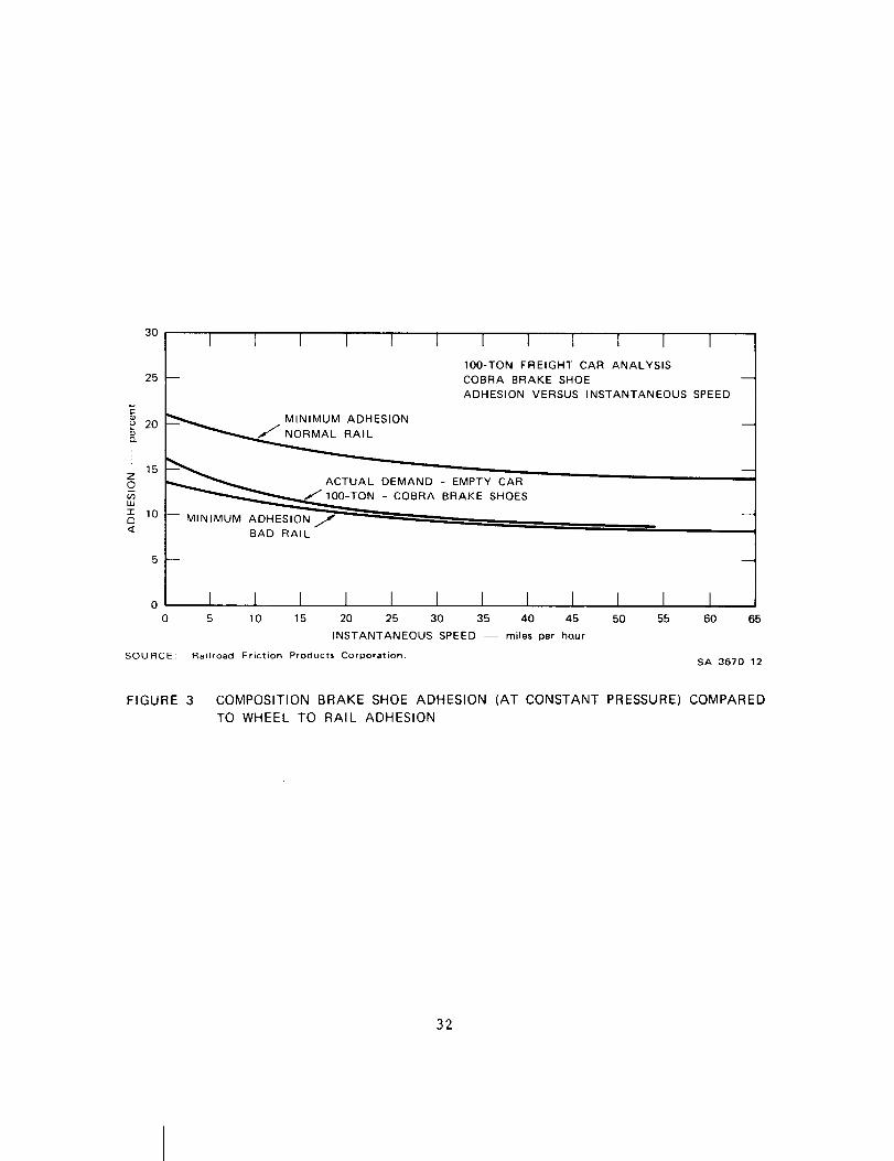
3O
25
o 20
!15
z0
uJ
-r 10121<
0
0
SOURCE:
I I I I I 1 I I I I I I
100-TON FREIGHT CAR ANALYSIS
-- COBRA BRAKE SHOE --
ADHESION VERSUS INSTANTANEOUS SPEED
. INIMUM ADHESIONNORMAL RAIL
_ _CTO_o_o - _tY _ --
--_'_'_0__0"_'0_f -BAD RAIL
I I I I I I I I I I I I5 10 15 20 25 30 35 40 45 50 55 60 65
INSTANTANEOUS SPEED -- miles per hQur
Railroad Friction Products Corporation. SA-3670-12
FIGURE 3 COMPOSITION BRAKE SHOE ADHESION (AT CONSTANT PRESSURE) COMPARED
TO WHEEL TO RAIL ADHESION
32

For effective stopping and ease of train handling, the coefficient
of friction should vary with speed such that the actual demand on adhesion
parallels the wheel-to-rail adhesion curve without exceeding it. The
variation of the coefficient of friction with speed for conventional
composition shoes is shown in Figure 4. When this is transferred to the
adhesion demand of an empty 100-ton freight car in the line of
Figure 3, the curve is nearly parallel to the wheel-to-rail adhesion
curves.
The static coefficient of friction of conventional composition
shoes is approximately 0.5. The dynamic coefficient of friction of
composition shoes is generally 0.27 to 0.32 depending on speed and
temperature. The friction value of composition shoes remains stable
until heated to about 200°F when an approximate 10-15% fade occurs. The
ocoefficient of friction then stays fairly constant until about 900 F
when fade is again likely.
The braking performance of currently used composition disc pads
appears to be satisfactory. The disc pad material is probably similar to
the composition material used in rail car brake shoes. The dynamic
coefficient of friction is about 0.35 and, as with brake shoes, some
fading is experienced at higher temperatures.
The composition materials used today appear to be very satisfactory
regarding braking performance. Only a material that experiences little
or no fade, such that its actual demand curve would be even closer to
paralleling the wheel-to-rail adhesion curve, could be expected to be an
improvement. If such a material had a greater coefficient of friction,
its value to braking performance might be even greater, particularly
with the railroads' trend toward the use of heavier freight cars.
2. Brake Shoe Life
Brake shoe life is determined by the wear rate of the friction
33

I I
0 1 I I I I I0 10 20 30 40 50 60 70
SPEED -- miles per hour
SOU RCE; Railroad Friction Products Corporation,SA-3670-13
FIGURE 4 VARIATION OF COEFFICIENT OF FRICTION WITH
INSTANTANEOUS SPEED
34
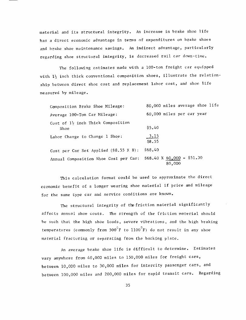
material and its structural integrity. An increase in brake shoe life
has a direct economic advantage in terms of expenditures on brake shoes
and brake shoe maintenance savings. An indirect advantage, particularly
regarding shoe structural integrity, is decreased rail car down-time.
The following estimates made with a 100-ton freight car equipped
with 1½ inch thick conventional composition shoes, illustrate the relation-
ship between direct shoe cost and replacement labor cost, and shoe life
measured by mileage.
Composition Brake Shoe Mileage:
Average lO0-Ton Car Mileage:
Cost of 1½ inch Thick Composition
Shoe
Labor Charge to Change 1 Shoe:
Cost per Car Set Applied ($8.55 X 8):
Annual Composition Shoe Cost per Car:
80,000 miles average shoe life
60,000 miles per car year
$5.40
3.15
$8.55
$68.40
$68.40 X 60,000 = $51.30
80,000
This calculation format could be used to approximate the direct
economic benefit of a longer wearing shoe material if price and mileage
for the same type car and service conditions are known.
The structural integrity of the friction material significantly
affects annual shoe costs. The strength of the friction material should
be such that the high shoe loads, severe vibrations, and the high braking
temperatures (commonly from 500°F to llO0°F) do not result in any shoe
material fracturing or separating from the backing plate.
An average brake shoe life is difficult to determine. Estimates
vary anywhere from 40,000 miles to 150,000 miles for freight cars,
between I0,000 miles to 30,000 miles for intercity passenger cars, and
between I00,000 miles and 200,000 miles for rapid transit cars. Regarding
35
disc pad wear, intercity passenger cars travel about i0,000 to 60,000
miles per set of disc pads. Rapid transit cars travel about 20,000 to
80,000 miles per set of pads.
Improved braking performance can be acquired by an increase in
brake shoe force (i.e., braking ratio), however, the shoe wear rate
increases with increasing force or braking ratio. Tests on composition
shoes indicate that the relative wear goes up as the square of the
increase in braking ratio (see Figure 5). It would appear then that
friction material with comparable wear characteristics to conventional
composition shoes, but with a larger coefficient of friction would require
less brake force for equivalent stopping and, therefore, would have a
reduced wear rate.
Associated with the increased wear rate of friction materials
with shoe force, is the effect of shoe temperature on wear rate. The
rate of wear of composition shoes tends to increase above 600°F. Aso
temperatures can rise to 500-700 F in normal service braking and to
700-900°F in emergencybraking, a friction material that resisted this
property of increased wear with temperature would be advantageous.
3. Wheel Milease
Improved wheel mileage can be of benefit to a railroad from both
safety and economic viewpoints. Thermal damage to a wheel can initiate
cracks in the wheel which, if grown with further thermal or mechanical
stress, can cause wheel failure which could result in a derailment.
Nonuniform wheel tread wear can require machining of the wheel, adding
expense and reducing life. Similarly, wheel locking and sliding, as a
result of a variance in the shoes' coefficient of friction and wheel-to-
rail adhesion, can wear flat spots on the wheel, causing stress buildup
* Braking ratio is a ratio of net brake shoe load divided by loaded car
weight, expressed as a percentage.
36

3
<LU
UJ> 2
t.-<._JLM
n..
1
I I I I I I/
0 10 20 30 40 50 60 70
BRAKING RATIO -- percent
SOURCE: Railroad Friction Products Corporation. SA-3670-14
FIGURE 5 EFFECT OF BRAKING RATIO ON SHOE WEAR OF A
COBRA SHOE
37
in the wheel if not corrected, and adding maintenance expense.
An estimate of the direct costs associated with overall wheel
mileage can be made with composition shoes on a 100-ton freight car.
Replacement cost and installation labor for a car set of 8 wheels mounted
on 4 roller bearing axles is $2000. Wheel costs per car year (based on
60,000 miles per year average car mileage and 230,000 mile wheel life
with composition shoes) is $520.
The heat created at the friction surface during braking can cause
the formation of hot spots on the wheels, resulting in thermal cracks
(small shallow cracks in the wheel tread) and spalling of small portions
of the tread between the cracks. Local hot spots on the tread which
exceed 1300°F while the average temperature of the wheel tread in contact
with the brake shoe is much lower, can result from nonuniform heating of
the wheel tread. The nonuniform heating is probably the result of uneven
shoe-to-wheel surface contact and pressure. The rate of heating and
cooling contribute more to the thermal cracking of the wheel than does
the total amount of heat introduced (i.e., maximum temperature reached).
A maximum of 25 braking horsepower per wheel is set by current
recommended practice to lessen the chance of wheel thermal damage. This
can, however, have the effect of limiting car tonnage if current speeds
and deceleration rates are maintained. A friction material that allowed
an increase in braking load without an increase in wheel thermal damage
would therefore be advantageous to the railroads. Also, it may be possible
to reduce the occurrence of hot spots by increasing the conformability
of the brake shoe to the wheel.
The tread profile of the brake shoe wear pattern on the wheel,
if not coinciding with the original wheel taper or if in the form of
grooves, can require machining of the wheel to correct the situation.
Composition shoes appear to perform satisfactorily with regard to wheel
wear.38

Finally, a variation of the friction material's coefficient of
friction with speed as comparedto wheel-to-rail adhesion at the same
speed, can contribute to wheel locking and sliding, resulting in flat
spots in the wheel tread. Flat spots generally require machining to
correct, which adds to maintenance cost and reduces wheel life.
Brake shoe chatter and squeal noise affects the public's appeal
toward the railroad as well as causing a possible occupational health
and safety hazard. The brake shoe should not emit any objectionable
or unhealthy odor which may be caused by high temperature braking.
Currently used composition shoes appear to perform quite well with
respect to odor and satisfactorily with regard to noise. Brake noise is
of most concern on passenger cars. Currently used disc brakes measure
less than 85 dBAat 15 feet, which is an acceptable level.
A comparison of the technical performance of a brake shoe to
shoe price gives an indication of the value associated with brake shoe
performance. A comparison of performance characteristics and prices of
cast iron, 3 percent phosphorous iron alloy, and composition shoes may
be useful as an indication. A 1½inch thick cast iron shoe has a price
of about $3.20 and a coefficient of friction value of approximately 0.15
to 0.20. A similar 3 percent phosphorous iron alloy shoe has a price of
$4.00 and the following improvementsover the cast iron shoe:
• Approximately twice the shoe life
• Significant reduction in sparking from shoe/wheel interface
• Higher coefficient of friction
• Coefficient of friction versus speed curve closer to wheel-to-rail adhesion versus speed curve.
A 1½inch composition shoe is priced at $5.40 and has the follow-
ing improvementsover a cast iron shoe:
• Approximately four times the shoe life
39

• Near elimination of sparking from shoe/wheel interface.
• Muchhigher coefficient of friction (0.27 to 0.33).
• Coefficient of friction versus speed curve very close towheel-to-rail adhesion versus speed curve.
• Less thermal damageto wheel
These figures indicate that no direct price association with
brake shoe performance exists. This is most obvious when comparing
shoe price and shoe life. Even a significantly improved new product
could probably only be given a comparatively modest increase in price
over currently sold composition shoes.
C. Market
Ninety-nine percent of all freight and intercity passenger railroad
traffic in the United States is carried by seventy-three Class I (i.e.,
annual operating revenues above $5 million) line-haul railroads.
Included in this category is the National Railway PassengerCorporation
(Amtrak), which is the primary intercity passenger carrier. In addition,
there are thirty commuterrailroad operations, eight heavy rail rapid
transit systems, and eight light rail rapid transit or streetcar systems
operating in the United States.
In the brake shoe industry, original equipment shoes are specified
by the railroad to the carbuilder, and replacement (after market) shoes
are purchased by the railroad directly from the brake shoe manufacturer.
In the disc pad industry, however, the carbuilder or brake builder
usually specifies the brake pads for the original equipment and the
railroad buys replacement pads from the carbuilder or brake builder,
rather than from the brake pad manufacturer. Due to much longer car life,
as comparedto brake shoe or pad life, the replacement market is by far
the greater in the rail car brake shoe and pad industry.
40

A breakdown of the numberand types of cars in service at the end of
1974 and projected figures for the next five years are given in Table 3.
The usage of brake shoes and disc pads varies according to the reauire-
ments for each railroad vehicle, and an overview of the current market
for brake linings in the railroad industry is therefore presented for
each of the vehicle categories listed in the table.
I. Freight Cars
There were 1,720,573 freight cars and about 15,000 cabooses in
railroad service at the close of 1974. This number varies relatively
little from year to year. There were 66,754 new freight cars placed in
service in 1974 and the average number of new freight cars placed in
service per year over the past 5 years is about 59,000 cars. An approxi-
mate equal number of freight cars are retired each year as new cars are
added.
Not all freight cars can use composition brake shoes because of
the much higher coefficient of friction of these shoes. The brake
system of most older freight cars is designed for metal shoes which require
a larger brake shoe force than is required with composition shoes for
equivalent braking effort. Similarly, metal shoes are not effective if
placed on cars with brake systems designed for composition shoes.
Approximately one-third of all U. S. freight cars or 600,000 cars are
equipped with composition shoes. In addition, nearly all of the
approximately 60,000 new cars installed each year are equipped with compo-
sition shoes.
It is estimated that the average 1½ inch thick composition freight
car shoe lasts approximately 80,000 miles on a freight car and that the
average car equipped with composition shoes travels about 50,000 miles
per year. As there are normally 8 brake shoes per car, an estimated
3 million composition brake shoes were installed on freight cars in 1974.
41

,uJ
ZO
F-_J
O
<
r,D
88 8 8 8O O _o a0 O
8 _" g
u -,1"
Z
g§g_g gOoo O
G i
g_ _ 8
O
r p
o=
c
i g 88888
rO
i.,.4 ,<
r-.. e,q e,_ r-. o
g g g g0 0 0 0
g888.... i
88 g gOOOO
.... i
OO
g 8 g 8i
g g g g
Cc)
g
.u
t_
u
.z-
_ °
o
_ 8
.,-4 _
t_
_ m
42
This number will probably be relatively stable in future years as the
increase of the proportion of freight cars using composition shoes and
needing replacements will be partially balanced by the reduction in the
average yearly car mileage for composition shoe equipped cars as these
cars become more common.
2. Locomotives
There were 28,355 locomotive units in service on Class I railroads
at the close of 1974. This number varies relatively little from year to
year, although there has been an average of about a one percent increase
in the locomotive unit fleet size each year for the past five years,
with the majority of the increase coming in the last two years. The
average number of locomotive units in service at any one time over the
last five years has been about 27,600 units. There were 1212 new
locomotive units placed in service in 1974 and average number of units
placed in service each year for the past five years is about 1200 units.
About one-fifth of all locomotives are switchers which use cast
iron shoes almost exclusively. Most of the new line-haul locomotives
installed in the last ten years use composition shoes; most of the older
locomotives still use cast iron shoes. Therefore, approximately 8000
line-haul locomotive units, most of which have one brake shoe for each
of its 12 wheels currently use composition shoes. An estimated I000 new
units per year in the near future will also use composition shoes. It is
estimated that the usual 2 inch thick shoe lasts approximately 80,000 miles
on a locomotive. A line-haul locomotive travels about 120,000 miles per
year. Consequently, it is estimated that 140,000 shoes were installed
on locomotives in 1974.
3. Intercity Passenger Cars
There were about 2200 intercity passenger cars in service in
1974. About 2000 of these are operated by Amtrak. Approximately one-third
43

of this fleet is equipped with disc brakes and the remaining two-thirds
is equipped with composition and metal brake shoes. The metal shoe
equipped cars, however, are currently being converted to composition
shoes. Amtrak has about 700 new disc braked cars on order, which with
the retirement of someolder cars may increase the intercity passenger
car fleet to over 2500 cars. The intercity passenger car trend is toward
disc brakes.
The average intercity passenger car travels about 130,000 miles
a year and both 2 inch thick composition brake shoes and ½ to 1 inch thick
disc pads last about 30,000 miles in this service. There is one brake
shoe for each of the 8 wheels on a passenger car so it is estimated that
50,000 composition brake shoes were installed on intercity passenger cars
in 1974. Disc braked passenger cars normally have two discs for each
of the four axles, and four pads are used with each disc. Consequently,
it is estimated that 80,000 disc pads were used in 1974.
4. Commuter Coaches
There were about 5200 commuter coaches in service in the United
States in 1974. About 5000 use tread brakes with composition shoes and
the remaining 200 use disc brakes. It is expected that about 600 new cars
with composition brake shoes and 200 new cars with composition disc pads
will be purchased in the next few years.
The average commuter coach travels about 50,000 miles a year and
2½ inch thick composition shoes and ½ to 1 inch thick disc pads last an
estimated 50,000 miles in this service. With 8 brake shoes per car for
tread braked cars and an estimated 16 disc pads per car for disc braked
cars, it is estimated that 40,000 composition brake shoes and 3000 disc
pads were installed on commuter coaches in 1974.
44
5. Heavy Rail Rapid Transit Cars
There were about 9400 heavy rail rapid transit (subway or
elevated) cars in operation in the U.S. in 1974. This number has remained
very stable with less an a 1 percent change from the average of 9360 cars
for the previous five years. About 6500 of these cars use metallic
tread brake shoes, 1450 use composition tread brake shoes, 750 use
composition drum brake linings, and 700 use composition disc brake pads.
In Table 3 , the drum brake lining figures are included in the brake shoe
figures.
The anticipated demand for new heavy rail vehicles, including
those of five transit systems not currently operating heavy rail vehicles,
is an average of about 400 cars per year for the next five years. Of
these, it is estimated that about 160 will be composition shoe tread
brake equipped and the remainder disc brake equipped. An average of
300 new heavy rail rapid transit cars were delivered per year over the
past I0 years. Therefore, an increase in the total number of these
vehicles operated in the U.S. by over I00 cars per year is anticipated.
Most of these cars will be disc brake equipped.
With one shoe for each of the 8 wheels of a heavy rail rapid
transit car, it is estimated that about 5000 2- to 2½-inch thick composi-
tion shoes were used on these cars in 1974. Simularly, with an average
8 disc pads per car, it is estimated that 4000 ½-inch thick composition
disc pads were used in 1974.
6. Light Rail Vehicles
There were about 1070 light rail rapid transit cars (streetcars)
in operation in the U.S. in 1974. This number has been declining by a
steady average of about 50 cars per year for the past 5 years. All of these
cars are equipped with metallic shoes or linings on tread or drum brakes.
45

Although the past trend indicates a declining market for streetcars
(1952 was the last year that a new streetcar was delivered in the U.S.)
streetcars or light rail vehicles (LRVs) are being considered as options
for newmass transit systems by more and more U.S. cities. With U.S.
Department of Transportation assistance, a standard LRVdesign was
established in recent years. SanFrancisco and Boston are purchasing
I00 and 175 of those new LRVsrespectively. These are disc brake equipped.
It is estimated that an average of about 150 LRVswill be purchased per
year for the next 5 years. Generally, these 6-axled LRVswill have one
disc brake per axle and the disc pads are specified to last 25,000 to
50,000 miles. These LRVswill travel an average of 30,000 miles a year.
7. Current Manufacturers and Prices
The three primary U.S. manufacturers of composition brake shoes
and disc pads for rail cars are the Abex Corporation, the Griffin Wheel
Company (friction material made by Raybestos Manhatten, Inc.), and the
Railroad Friction Products Corporation. Due to the expanding U.S.
market for rail car disc pads, other U.S. and foreign friction material
manufacturers are entering this market.
Table 4 outlines the common sizes and prices of currently used
composition brake shoes and disc pads by rail car type. Commonly, a
manufacturer will use nearly the same formulation for all his brake
shoes, although disc pad formulations frequently differ from the brake
shoe formulations.
46

TABLE4
COMMONSIZESANDPRICESOFRAIL CARBRAKESHOESANDPADS
Type Car and Brake
Freight car tread
Freight car tread
Locomotive - tread
Intercity Passenger - tread
Commuter Coach tread
Heavy Rapid Transit - tread
Intercity Passenger - disc
Heavy Rapid Transit - disc
Approximate Size of Brake Shoe*
(Length x Width x Thickness]
or Disc Pad (Surface
Area x Thickness)
13 in x 3½ in x 1½ in
13 in x 3½ in x 2 in
16 in x 3½ in x 2 in
14 in x 3½ in x 2 in
16 in x 3½ in x 2½ in
12 in x 6 in x 2 in
62 sa in x 1 in
55 sq in x ½ in
Current Price in
Pallet Quantity •
$ 5.40
6 24
7.90
7 20
7 90
13 30
10-15
3-7
Most composition tread brake shoes have one or more slots across the
shoes length totaling about i-2 inches.
Price includes backing plate for brake shoes.
47

V I I I. AIRCRAFT
A. Background
The use of organic friction materials in aircraft brakes is cur-
rently limited primarily to small general aviation aircraft. The trend
in larger aircraft brake materials has been toward higher energy absorp-
tion per unit mass of brake materials. Aircraft size and brake temperatures
have risen through the years, and on larger aircraft, organic friction
materials have been replaced by more expensive copper- and iron-based
metallics. Composition friction materials are used on almost all single-
engine and a few twin-engine piston general aviation aircraft of a maxi-
mum gross weight of about 8000 pounds.
The brakes of these small aircraft are used dynamically during land-
ing and taxiing and statically during pretakeoff engine runup. During
landing, the speed of an airplane is usually below 60 mph before the
brakes are applied. If the runway is large enough, coasting is often
used to slow the plane before the brakes are applied for taxiing and turn-
ing. During a no1_al landing, brake temperatures are commonly between
o500-800 F.
Be£ore about 1960, most general aviation airplanes were equipped
with drum brakes. Since then, disc brakes, with one brake for each of the
two main landing gears, have been common. Each brake uses a single steel
disc about 8 inches in diameter. The discs are frequently made from a
nonheat-treated steel, such as SAE 1018 steel. Brakes in common use have
two, four, or six brake segments per brake. The number of segments used
affects the brake assembly size. For example, a two-segment brake requires
48

a single piston caliper brake assembly with about a 2000-1b brake segment
force in normal braking, whereas a four-segment brake requires a double
piston caliper brake assembly with a normal brake segment force of about
3300 pounds. Over half of the small airplanes use two-segment brakes and
most of the remainder are four-segment brakes. The segments are madeof
an organic asbestos and brass chip composition material and are commonly
riveted to the metal backing plate.
B. Product Requirements and Performance
The properties of importance in small airplane friction materials
are the coefficient of friction, wear, disc wear, and price.
The level of coefficient of friction is most important in regard to
a desired improvement over the conventional organic composition _riction
materials. The dynamic coefficient of friction has a large effect on the
size and weight of the brake assembly. A friction material with a sig-
nificantly higher coefficient of friction could allow a reduction in the
size and weight of the brake assembly. A reduction in equipment weight
and size would be of great economic benefit to the airplane manufacturer
and user. In addition, a reduction in the brake assembly size and com-
plexity, such as from a double to a single piston caliper brake allowed by
a friction material with a higher coefficient of friction, would allow a
significant reduction in the brake assembly cost. Finally, an organic
composition friction material with a significantly higher coefficient of
friction could possibly be used on more of the twin-engine general aviation
airplanes. A reduction in segment and brake assembly cost would thus be
possible for these airplanes, since currently used metallic segments cost
two to four times more than equivalent organic composition segments. The
conventional organic composition friction materials used have a dynamic
coefficient of friction between about 0.36 when cold to about 0.25 when hot
_9

(about 800°F). Conventional metallic (iron and copper) materials have a
coefficient of friction between about 0.45 whencold to about 0.33 when
hot.
Conventional organic friction materials perform quite satisfactorily
with respect to the other properties of importance in the airplane brake
segment. The conventional materials can fade somewhat with increased brake
heating, but improvement in this property is not needed for the airplanes
currently using organic composition brake segments. The lack of fade in
combination with a higher coefficient of friction might increase the pos-
sibility of an organic composition segment being used on airplanes where
metallic segments are now used however. Smooth retardation is of impor-
tance since the landing gear is sensitive to low frequency vibrations.
Segment life commonly varies between one-half year to two years, depending
on the frequency and type of airplane use. It takes one hour to reline a
single engine plane and about 2-2½ hours to reline a twin-engine plane.
With labor rates of about $15.00 per hour, this can be significant expense.
The cost of the friction material itself is also of economic importance
with regard to wear.
As with most organic composition friction materials, the wear rate
tends to increase at higher temperatures. Dimensional stability and
structural integrity are of importance with respect to the rate at which
ohigh altitude-cooled brake segments can heat to I000 F and above during
braking in landing.
In summary, conventional organic composition friction materials used
primarily on single-engine airplanes perform quite satisfactorily, al-
though a significant increase in the dynamic coefficient of friction would
be of value to the airplane manufacturers and users.
5O

C. Market
General aviation aircraft have four basic areas of use: business,
commercial, instructional, and personal. The bulk of the business general
aviation aircraft are the larger multiengine aircraft that use metallic
brake segments. Most commercial, instructional, and personal general
aviation aircraft are equipped with brakes that use organic composition
brake segments.
In the general aviation aircraft industry, the brake segments are
commonly manufactured by a friction material manufacturer and sold to the
brake manufacturer who installs them in the original equipment. In the
afte_arket, the segments go through the chain of friction material manu-
facturer, airplane brake manufacturer, airplane manufacturer, and airplane
dealer or distributor before they are sold to the airplane owner.
In 1972, 109,256 single-engine and 17,855 multiengine fixed-wing air-
craft were registered in the United States. Of the multiengine aircraft,
approximately 5 percent use organic composition brake segments. Almost
all single-engine airplanes use organic composition disc brake segments.
Therefore, approximately i00,000 airplanes currently use organic com-
position segments in their brakes.
Three companies manufacture most of the airplanes that use organic
composition brake segments. These companies delievered a total of 6433
airplanes in 1971, 8227 airplanes in 1972, and 11,605 airplanes in 1973.
The 1973 number is more representative of the sales of 1965-69, before the
1970 economic downturn. The 1973 figure is probably representative of the
average expected shipments per year. Most of these deliveries use organic
composition brake segments, consequently, an estimated I0,000 new air-
planes are delivered per year with organic composition brake segments.
51

The average general aviation aircraft flies about 200 hours, or
about 24,000 miles per year. Brake segmentslast an average of about
one year on these small airplanes. Commonly,the brake segment is a 45
degree segmentof a 7½-in. OD, 5½-in. ID ring that is _-in. thick. About
60 percent of the airplanes use two segmentsper brake and most of the
remainder use four segmentsper brake. Consequently, an estimated 600,000
organic composition brake segmentsfor aircraft are used per year.
The two primary manufacturers of organic composition brake segments
for general aviation airplanes in the United States are AbexCorporation
and Raybestos_lanhatten, Inc. The samesize brake segmentis madeby both
manufacturers. These manufacturers sell the segments for about $0.50 each
in large quantities to the airplane brake manufacturers.
52

IX. BRAKE LINING MANUFACTURING PROCESSES
There are at least six basic methods of making brake linings , which
are described briefly below:
A. Dry Process
All dry-process brake linings have as the major binder a dry "B"
stage resin. In effect, a "B" stage resin is a thermosetting resin
mixed with an intermediate and set in a partially cured condition.
When the partially cured resin is reheated, it softens and becomes
plastic. In the dry-processing of brake linings, this phenomenon is
useful in the following way. All the weighed ingredients are first
mixed in a tumbling barrel or similar mixer. A weighed portion of the
mixed material is then spread uniformly in a shallow mold, which is
placed in a hot press and heated under low pressure for a sufficient
time and to a temperature that will cause the resin to flow and set,
but not be fully cured. The resulting flat sheet is removed from the
mold and cut into the developed section of the desired arcuate
brake segment. This flat rectangular segment is then reheated to
soften the resin and quickly formed to brake-lining shape on a cold mold
which resets the resin. A final baking of the segment in restraining
molds to retain shape converts the resi_ to a thermoset, or permanent,
condition. The final cure, or bake, is dependent on the type of resin
and the end usage.
B. Extruded Processes
Extruded brake linings are manufactured by three different processes.
Kirk-Othmer, Encyclopedia of Chemical Technology, (19667
53

Twoof these processes are similar in that both extrude a plastic, flat
tape of lining through a shapednozzle. The processes differ mainly in
the meansof application of the pressure on the plastic mass. One
process applies direct hydraulic or air pressure on a ram forcing the
material out, whereas the other process uses a screw-feed to extrude
the stock into a continuous tape.
In the extruded process, all the ingredients are mixed together with
a wet binder which maybe resin, oil, rubber, or various combinations.
The binder contains sufficient solvent to yield a putty-like masswhose
consistency must be closely controlled to produce dense tape with good
wet-strength.
After extrusion, in both processes the tape is dried in rolls and
then finish-cured to shape in confining molds.
The third type of extrusion is knownas roll forming. In this
process, as in the first two, the lining is mixed, but it is less plastic,
and after mixing consists of free-flowing, very slightly tacky granules.
Thesegranules are fed into the nip of two form rollers which compress
the mixture into a continuous tape. The lining is then processed
similar to the other types of extruded material. A variant of this
process is the introduction of a I/8-in_-mesh wire on the bottom roll
to form a wireback lining. Roll forming produces a good quality of
lining at low cost.
C. Wet Board Process
The wet board process of making a brake lining consists of adding all
the ingredients except the binder to a beater or hydrapulper with a
quantity of water. The mixed wet pulp is then further diluted and
fed to a paper-making machine and formed into a thin sheet on a blanket,
from which it is transferred to a revolving cylinder where it builds
54

up to brake-lining thickness. The cylindrical deposit is cut from the
roll to form a rectangular sheet which is dried and cut into the
developed shape of an arcuate segment. The flat strip is then saturated
in a liquid binder and either air- or oven-dried to remove solvents.
At this stage, the binder is sufficiently flexible to allow forming into
a curved mold for final cure.
D. Sheeter Process
A sheeter is a variant of a rubber mill which consists of one
large, heated roll and one smaller, cold roll. These rolls revolve
in opposite directions, creating a nip. The feed consists of a solvated
rubber (natural or synthetic) that is mixed with asbestos and other
ingredients in a heavy-duty mixer. The plastic mixture is fed into
the nip of the rolls and a sheet builds up slowly on the hot roll.
The gap between the rolls is automatically made to open further as
the material thickens on the hot roll. The sheet is built up to
thickness and is then slit from the roll in brake lining widths.
Forming and final cure are similar to other processes.
E. Sintered Metal Process
Being distinctly different from the previously described methods,
this process uses a metallic matrix in which the lubricants, fillers,
and friction augmenting agents are held mechanically. The metal matrix
is comprised of a powdered metal or metals of I00 mesh or finer. The
commonest matrix is a copper-tin alloy, usually consisting of about
90% copper and 10% tin. Another popular matrix is an iron-carbon
base. As an example, powdered metal normally comprising abaut 65%
by weight of the batch is mixed with silica flour, graphite, and
usually, lead. A weighed amount is placed in a mold and pressure of
55
about 15,000 psi is applied by meansof a hydraulic press. The result
is a thin fragile wafer of material known as a cookie. Because sintered
metal is structurally weak, it is commonlybrazed to a metal memberby
placing the pressed wafer on a copperplated steel plate and applying
pressure during heating in a furnace with a controlled atmosphere. At
a temperature of about 1400CF, the time required for the copper-tin
matrix is three hours. During this heat cycle, the copper-tin matrix
fuses or sinters to the steel plate and the powderedmetal particles
sinter or bond together at their contact points, trapping the nometallic
ingredients. Flat discs can be madedirectly with suitable molds, and
curved segmentscan be madeby processing to shape through a three-roll
bender. Thick curved segmentscan be formed but with difficulty.
F. Woven Process
Linings made by this method are more expensive than linings made
by the processes described above, because this process requires the
spinning of Grade 3 Asbestos fibers. The fiber is "opened" in a hammer
mill and is processed into asbestos yarn, usually with cotton comprising
some 30% of the mixed fiber. The yarn is woven into tape and saturated
or calendered with various binders and fillers. Final processing may
produce a flexible roll lining, or rigid segments.
56
X. BRAKELINING TESTING
In addition to actual vehicle testing of a brake lining material,
the industry uses several laboratory test machines to characterize
friction materials. These laboratory friction machines can be used to
examine both wear rate and friction properties of the test materials.
Although vehicle testing appears to be the only completely reliable
method of testing brake lining material, laboratory tests are very useful
and exhibit a numberof advantages, such as:
(I) Test environment is controlled and the highly variable environ-
ment experienced during full-scale vehicle testing is avoided.
(2) Test hours can be accumulated at a continuous rate, unhampered
by weather conditions, hours of daylight, and legal restric-
tions placed on highway operation of vehicles.
(3) Testing in the laboratory is muchsafer than highway vehicle
testing becausehigh-speed driving and brake application with
untested materials are avoided.
(4) Laboratory tests cost less than vehicle testing because after
initial equipment costs, even though these are very high,
dynamometertest equipment has long life and low maintenance
costs.
A. Dynamometer Testin$
Dynamometer testing can be separated into two categories: bench-
scale dynamometer test equipment and full-scale brake dynamometer testing.
57

In bench dynamometertests, a small piece of the friction material is
operated against a moving mating surface, and the forces produced by
the friction couple are measured. Tests are conducted on a small scale,
and results obtained more rapidly than with full-scale dynamometertests.
Results obtained on be:_chdynamometersare only an indication of results
which will be experienced in a vehicle brake system. Testing done with
a full-scale brake dynamometer,on the other hand, uses a full-scale brake
and the brake lining as it is actually manufactured. This type of
dynamometertesting gives a nearly complete description of the friction
and durability characteristics of the lining. The dynamometertest
machines used in the testing of brake linings are described below.
I. Friction Material Test Machine (FMTM)
This bench dynamometer, developed by the General Motors
Corporation, attempts to record the brake lining performance by sub-
jecting it to controlled conditions of pressure and temperature at the
friction interface, and speed. A small l-sq. in. sample is pressed
against the interior of a rotating drum. The temperature of the rotating
drum is controlled and, due to the large surface area in relation to the
test sample, the sample temperature reaches that of the bulk drum tempera-
ture. The friction force exerted by the rotating drum against the lining
sample is measured, and the coefficient of friction may be calculated.
The lining and drum may be operated through a broad range of temperatures,
pressures and speeds to simulate test procedures conducted on a full-scale
brake assembly.
The FMTM is capable of subjecting the friction material to a
broad range of interface conditions and eliminates the influence of
external factors that are present in vehicle testing. However, it has
not been found possible to correlate results obt_ned on the FMTM directly
to actual brake operation. The machine has been found to be valuable as
58

a quality control test and is quite acceptable in comparing materials
from various batches.
The test procedure used for testing friction materials on the
FMTMis SAEJ661a. This test procedure is referred to as a brake lining
quality control test, and its purpose is to establish a standard test
for obtaining and reporting the friction and wear characteristics of
brake lining materials.
2. Friction Assessment Screenin$ Test (FAST) Machine
This bench dynamometer was developed by the Ford Motor Company
and is operated according to a standardized test procedure developed by
Ford. The FAST machine operates by pressing a 0.5 -sq. in. test sample
against the flat face of a 7 in. diameter cast iron disc, rotating at a
constant speed of 870 rpm. The applied force on the test specimem pad
may be either constant or furnished by a piston, controlled by a servo
valve. The servo valve is in turn controlled by the friction force pro-
duced by the test specimen. When the pressure is controlled by a servo
valve to produce a constant friction force, the rate of energy dissipation
remains constant. The disc temperature will gradually increase with time
at a standard rate and a plot of the applied force versus time is, in
actuality, one of force versus time, temperature increase. The coefficient
of friction may be calculated, and test results from this machine will
give friction versus temperature and friction versus time and temperature
data. The friction versus time, temperature values are similar to the
fade mechanism in conventional braking systems and, therefore, this
test gives some correlation with lining fade characteristics. The FAST
machine subjects a test specimen to a single heating run without recovery .
The FAST test is relatively simple and quick. Some degree of
correlation has been observed between FAST test results and actual brake
lining performance. Basic design of this machine resembles that of a
59
disc brake, and a greater degree of correlation of test results with
actual brake operation can be observed with disc brakes than with shoe
brakes with servo action.
Results obtained with the FASTmachine have proved to be quite
reproducible, and no specialized operator skill is required. These
characteristics make the FASTa useful standard quality control test.
Although both the FMTMand the FASTmachines are useful testing
equipment, neither appears to give adequate correlation to vehicle
operation. A. R. Spenceet al. have offered a theory on why friction
material test machines, using test specimens that are small comparedto
the rotating disc or drum, do not give data representative of vehicle
performance ("Four Tests for Consistency of Automotive Brake Linings",
Paper No. 660412presented at SAEmeeting, June 1966).
3. Single End Inertia Dynamometer
This inertial dynamometer gives complete friction and durability
characteristics of a friction material, and allows direct comparison to
actual vehicle performance of the material. In this type of dynamometer,
an actual brake mechanism is incorporated or, in some cases, the machine
uses a scaled version of the brake assembly.
The machine consists of the rotating part of the brake, which
is a rotor in the case of a disc brake, or a drum in a conventional shoe
brake. The stationary part of the brake is the caliper head for a disc,
or the backing plate holding the brake shoe, for a drum brake. Brake
pressure is regulated by a hydraulic brake assembly system.
Instrumentation of this dynamometer is as follows:
(a) A tachometer to record rotating speed.
(b) A pressure gauge to record brake actuation pressure.
60

(c) Thermocouplesand recorder to obtain brake linings
temperatures.
(d) Recorder to obtain instantaneous brake torque data.
(e) Optional recorder to record all pertinent outputs and
inputs including speed, brake torque, temperatures and
pressures.
The dynamometermust also be equipped with an air supply capable
of simulating the air cooling of a vehicle brake assembly, due to its
forward motion.
4. Dual End Inertia Dynamometer
Throughout the brake lining industry, the dual end inertia dyns-
mometer is considered the most precise method for simulating actual vehicle
performance. The reason why this machine is not used to a greater extent
is its initial high cost.
Basically, the dual end inertia dynamometer incorporates the same
instrumentation as the single end dynamometer. The difference is that
the dual end dynamometer is operated with one front and one rear brake
assembly, simulating the torque transfer from front to rear in vehicle
brake performance. A considerable amount of testing has been performed
on this type of dynamometer and a high degree of correlation with vehicle
brake performance has been found. However, vehicle brake temperatures
during fade tests are difficult to reproduce with the dual end dynamometer.
An important consideration with testing on the dual end dynamometer
is that if a brake standard were devised for use with this dynamometer,
current merchandising practice of supplying linings in axle sets would
have to be changed. This would be necessary because performance observed
on this dynamometer during the dual-brake tests is the combined per-
formance of front and rear brakes and would require linings to be sold
61
in vehicle sets.
Both the single end and dual end inertia dynamometersare
capable of simulating vehicle tests in accordance with the FMVSS105
regulation for passenger cars and the FMVSS121 regulation for trucks
and buses.
B. Standard Dynamometer Test Procedures
Any test procedure which is within the capability of the dynamometer
can be devised; however, certain specific procedures are in existence
and are considered standard. Since performance of a friction material
will vary depending on the brake and the vehicle on which it is used,
testing must often be done under conditions simulating several different
vehicles and braking system. The standard test procedures of dynamometer
operation may be used with any of the brakes and vehicle conditions. In
practical testing, certain specific brakes and the vehicle most likely
to use these brakes must be selected, to ensure that testing remains
economically feasibly. Alternatively, when comprehensive testing is
required, such as in the case of a new model of passenger car, an
extensive test program will be conducted on the specific brake and
vehicle combination.
For the following types of tests are conducted on a full-scale
brake dynamometer:
(a) Break-in or burnish results
A series of stops are made at specific intervals from a
constant speed and the hydraulic pressure to the brake is
controlled to maintain a constant deceleration rate from
stop to stop. The pressure required to maintain constant
deceleration is recorded to indicate the stability of the
friction level of the lining.
62

(b) Effectiveness of performance curves
The curves consist of a series of stops from a specific speed
with each stop made at a higher application pressure than the
previous one. The deceleration rate is measured and in this
way, the change of coefficient of friction of the lining with
increasing pressure is determined. Effectiveness curves
are usually run at several different speeds, and also serve
to determine any change in friction with speed and the
consequent increase in energy and heat produced.
(c) Fade
A fade run consists of a series of stops made at constant and
close intervals, usually from a fairly high speed. Line
pressure to the brake is regulated so as to maintain constant
deceleration time, hence constant output. The fade run shows
the tendency of the lining to lose friction as it rapidly
overheats from abusive use. Obviously, a lining material
which loses friction very rapidly is highly undesirable, but
one which shows no reduction of friction can also be dangerous,
such as if the lining or other brake components reach a tem-
perature which results in catastrophic failure without the driver
of the vehicle receiving any warning of the impending danger.
Basically, a lining should be resistant to fade, but fade
should occur and its onset should be reasonably gradual.
(d) Recovery
A recovery run is made following a fade run, with longer
intervals between stops than used in the fade run, and at
considerably lower speeds. The purpose of the recovery run
is to determine the trend of the coefficient of friction of
the lining material as it returns to normal temperature,
63

(e)
(f)
following the excessive heating experience during the fade.
An initial drop in friction is not unusual during the early
stages of recovery known as a "hole in the recovery," but
obviously, this characteristic must be limited to a tolerable
value.
Stability
Erratic changes in measured test results during a dynamometer
run indicate an unstable lining material which will result
in erratic performance such as uncontrollable pulling of the
vehicle to one side or the other in actual road operation.
Noise
Noise is an important aspect of brake lining operation and one
of the most difficult to measure on a dynamometer. A fairly
successful method is to operate a brake under conditions that
are prone to cause noise in actual vehicle operation and observe
the generation of the conditions in the brake that have previously
been found to correlate with vehicle noise. Noise is most often
found at low speeds and under lightly loaded conditions and
often takes a considerable length of time to develop. There-
fore, noise test procedures have consisted of many low-energy
stops simulating typical moderate operation of vehicle brakes.
A lining which ultimately produces a noisy brake has been
found to have a tendency to polish the brake drum or rotor
which it contacts. This observation agrees with theoretical
conditions and has allowed some measurement of noise-producing
tendencies of brake linings by measuring the degree to which
the drum, or rotor surface, is made smoother during a long
series of low-energy stops. In this type of testing, abusive
stops must be avoided, because they produce a high wear rate
64

of both the lining and the drum, which tends to recondition
both surfaces and hide the polishing effect of the lining.
C. Motor Vehicle Tests
Vehicle testing is the most realistic and reliable meansof testing
a brake lining material. Vehicle testing ranges from normal driving
making infrequent stops to high-speed driving and manysudden "panic
stops".
Fleet test cars are equipped with decelerometers, line pressure gages
reading brake pedal load, electric counters recording stops, and lining
and drum temperature recording devices. Complete tests maybe 3000
miles, subjecting the brake lining to the equivalent of 20,000 miles
or more of normal driving. Wearmaybe determined by measuring lining
thickness before and after testing; brake lining wear is normally
recorded in inches per thousand stops.
Braking systems on all U.S. motor vehicles are required to conform
to certain performance and equipment standards. The regulations are
written by the National Highway Traffic Safety Administration for the
purpose of ensuring safe vehicle braking performance. The regulation
covering trucks and buses equipped with air brake systems is FMVSS121.
Cars and light trucks must meet standards set forth inFMVSS 105.
A number of product quality tests are also performed by brake
lining manufacturers. Physical properties such as tensile and flexural
strength, density, impact, odor, coefficient of linear expansion,
coefficient of heat transfer, and permanent expansion or contraction
after one hour at 450CFare determined. Manyof these properties are
determined for quality control purposes, and the data often indicate
how a brake lining will perform in actual operation.
65

D. Rail Car Brake Lining Tests
Product development and testing of new brake shoes or disc pads for
rail car application follow the general outline given for automotive
testing. For composition brake shoes, however, the Association of
American Railroad's (AAR) specification M-926-72 must be passed before
the shoe can be accepted in interchange freight and passenger service.
The specification outlines a series of dynamometer tests to determine
if the shoe meets the minimum acceptable requirements. The dynamometer
friction and wear tests include a grade test series measuring retarding
force, shoe wear, and wheel temperature produced by a constant brake
shoe load at 25 mph wheel speed for 45 minutes, a light braking stop test
series, each measuring gross stopping distance for five initial speeds
with a constant shoe force, a static friction test measuring the torque
required to start wheel movement with a given shoe force, a shoe wear
test, and a spark test. The minimum coefficient of friction acceptable
for the light and heavy brake tests are 0.32 and 0.27 respectively.
The minimum static coefficient of friction acceptable is 0.38. Thei
full specification can be obtained from the AAR.
The AAR brake shoe test is the only industry-wide specification
on brake shoes. The AAR specification is not easy to meet, however,
and is therefore considered a good measure of a quality brake shoe.
Although it not law, very few railroads would purchase a composition
brake shoe that does not meet the AAR specification. The U.S.
Department of Transportation has no regulations or specifications on
brake shoes or disc pads for rail vehicles.
No government regulations or railroad industry specifications
exist that cover the performance of rail car disc brake pads. As
with brake shoes, however, many rail car manufacturers and railroads
have their own vehicle tests for new products. Some use the break-
66
away test, which basically entails pulling a rail car up to a set speed,
removing it from the locomotive, and then applying the brakes and
measuring instantaneous deceleration rates, brake shoe forces, and
stopping distance.
Each individual transit authority has their ownrapid transit
car specification. The specification used by the U.S. Department of
Transportation for its State of the Art Car rapid transit car may
be representative. This specification requires a 105,000 pound car
with an initial speed of 40 mph to have a maximumdistance to stop
of 450 feet in service friction braking and 425 feet in emergencyfriction
braking. At 80 mph initial speed it requires 425 and 2200 feet respectively.
The complete specification can be obtained from the U.S. Department of
Transportation.
E. Aircraft Brake Linin$ Tests
No government regulations exist exclusively on performance of
brake lining materials for use on aircraft. However, regulations
do exist covering the entire braking system of the aircraft, of which
the friction material is an important component. Any friction material
for use on any brake, on any airplane, must qualify by tests outlined
by the U.S. Department of Transportation's Federal Aviation Administration.
These tests for small aircraft can be found in the Code of Federal
Regulations, Title 14- Aeronautics and Space, Chapter I- Federal Aviation
Administration. In Part 37, Section 37.172, a dynamometer test is
outlined requiring 35 design landing stops at a deceleration rate of
I0 ft/sec 2. As a measure of wear, only one change of segments is
allowed during this test series. A taxi and park test is included in
Part 23, Section 23.735, which specifies the kinetic energy that the
brake system must be capable of handling and specifies that the brake
must be capable of holding the aircraft stationary with take-off
67
power on the critical engine. Section 23.75 outlines the horizontal
stopping distance required for a landing.
The airplane manufacturer frequently runs his own dynamometerand
field tests. At least one manufacturer, for example, requires the
segmentsto pass i00 stops instead of the 35 called for in the test of
Section 37.172.
68

XI. CONCLUSIONS
This study of the markets for improved brake friction materials
and the technical requirements and constraints associated with such
improvements leads one to the following conclusions.
Passenser Cars and Lisht Trucks
This industry is probably the most cost conscious of any that
were studied in this survey. A new brake lining material with improved
coefficient of friction stability would be desirable, but any cost
increase would have to be minimal. A brake lining material, incorpo-
rating the following improvements, but equal in cost to conventional
linings, however, would penetrate the brake lining market for this
industry:
• Reduced wear
• Reduced drum wear
• Elimination of noise (disc brake applications).
Trucks and Trailers
An improved friction material equal in performance to conventional
brake linings, but having the following improved properties, would be
quite advantageous to this industry:
• Reduced fade, more stable coefficient of friction at
elevated temperatures.
• Reduced lining wear
Reduced drum wear
69

• Capability of meeting present FMVSSI21regulation and proposed
regulation of 245 ft stopping distance at 60 mph.
Equality in price to conventional linings, or no more than
40%increase.
A price increase of 40%over conventional lining materials would
necessitate considerable improvement in each of the other categories
listed above, for a new lining material to be accepted by the trucks
and trailer industry.
Buses
A definite market exists for a new brake lining material for use
by the busing industry. This material must be equal in performance
to conventional linings and exhibit the following improvements:
• Reducednoise
Reducedfade, more stable coefficient of friction at
elevated temperatures
Reducedlining wear
• Reduceddrumwear
• Comparable in price to conventional linings or no more than
40%increase.
The bus industry seemsto be actively seeking brake lining materials
with the above improvements. A new lining with these qualities is
definitely needed but must be cost effective in relation to drum and
lining wear.
Asricultural_ Construction_ and Industrial Equipment
A considerably more detailed study of these industries would be
required to make an accurate determination of friction material
properties required of a new brake lining material. However, the
70
industrial equipment sector could definitely provide a significant
market for a new brake lining material that incorporates the following
improvements:
• Reduced wear
• Significant reduction in or elimination of asbestos content.
• Tolerable cost increase; material should be cost effective in
relation to wear rates.
Rail Cars
Brake Shoes--A new friction material that is at least equal in
performance to currently used composition rail car brake shoes and has
a significant improvement in any or all of the following characteristics
with no more than a 40% price increase would make a marketable rail
car brake shoe product:
• Reduced wheel wear
Reduced wheel thermal damage
• Reduced brake shoe wear
In addition, a significant improvement in any of the following
characteristics without any price increase would make a marketable
brake shoe:
Reduced coefficient of friction fade
Reduced shoe icing
Reduced braking noise.
Disc Pads--A new friction material that is at least equal in
performance to currently used composition rail car disc brake pads and
has a significant improvement in either or both the following charac-
teristics with a price increase would make a marketable rail car
disc pad product:
• Reduced pad wear
71
• Reduceddisc wear
In addition, a significant improvement in any of the following
characteristics without a price increase would makea marketable
disc pad:
O
O
Reduced coefficient of friction fade
Reduced braking noise
Aircraft
A new friction material that is at least equal in performance
to currently used organic composition small airplane disc pads and
has a signilicantly higher coefficient of friction with a maximum
100E price increase would make a marketable airplane disc brake
segment product.
72
APPENDIXLIST OF TERMS
Brakin$:
The conversion of the energy of motion (kinetic energy) of a
vehicle mostly into heat energy. The heat may be calculated by the
formula KE = ½ mv 2 where KE is the kinetic energy, m is the mass, and
v is the velocity of the vehicle.
Brake Linin$:
Brake lining is a friction material used for stopping or retarding
the relative movement of two surfaces.
Coefficient of Friction:
The effect of friction between any two materials can be measured
and represented by a relationship which is known as the "coefficient
of friction." This relationship is the ratio between two measured
forces and is always represented by a fraction in which the numerator
is less than the denominator. The denominator of the fraction is the
normal force pressing the two surfaces together. The numerator is the
frictional force resisting the motion of one surface over the other
when a force is applied parallel to the contacting surfaces. The
coefficient of friction determined when one surface slides over the
other is the dynamic coefficient of friction; the coefficient of
friction determined when one surface does not slide over the other
with maximum force parallel to the surfaces is the static coefficient
of friction.
73

Friction Material:
A product manufactured to resist sliding contact between itself
and another surface in a controlled manner.
Ranges of Friction:
Friction material is given a friction rating (coefficient of friction)
with the notation whether the value is for dry or wet (oil) operation
and whether it is dynamic or static friction. In dry operations, friction
material may be said to be available in the range of 0.I to 0.60. A
material whose friction is less than 0.i is usually regarded as a
bearing material.
74