Bradford White ElectriFLEX HD (Heavy Duty) Commercial ... · Bradford White ElectriFLEX HD™...
28
Save this manual for future reference Manual 238-51791-00A REV 1/16 Effective: January, 2016 ECO 7960 SERVICE MANUAL Troubleshooting Guide and Instructions for Service (To be performed ONLY by qualified service providers) Models Covered by This Manual: CEHD(50,80,120)(A) Bradford White ElectriFLEX HD ™ (Heavy Duty) Commercial Electric Water Heater CEHD SERIES Immersion Thermostat Models
Transcript of Bradford White ElectriFLEX HD (Heavy Duty) Commercial ... · Bradford White ElectriFLEX HD™...

Save this manual for future referenceManual 238-51791-00A REV 1/16Effective: January, 2016 ECO 7960
SERVICEMANUAL
Troubleshooting Guideand Instructions for Service
(To be performed ONLY byqualified service providers)
Models Coveredby This Manual:
CEHD(50,80,120)(A)
Bradford White ElectriFLEX HD™ (Heavy Duty)Commercial Electric Water Heater
CEHD SERIESImmersion Thermostat Models

2
2
Commercial Electric Energy Saver Water Heater
Table of ContentsIntroduction................................................................................................................... 3Tools Required for Service ........................................................................................... 3General Information ...................................................................................................... 4Sequence of Operations ............................................................................................... 9Troubleshooting.......................................................................................................... 10Service Procedure I: Heating Element Testing ......................................................... 12Service Procedure II: Line Voltage Testing ............................................................... 13Service Procedure III: Fuse Testing .......................................................................... 14Service Procedure IV: Hi Limit Switch Testing .......................................................... 15Service Procedure V: Thermostat Testing ................................................................ 16Service Procedure VI: Contactor Testing .................................................................. 18Service Procedure VII: Thermostat Removal and Replacement ............................... 19Service Procedure VIII: Hi Limit Switch Removal and Replacement ......................... 20Service Procedure IX: Heating Element Removal and Replacement ........................ 21Service Procedure X: Anode Inspection and Replacement ...................................... 22Parts List .................................................................................................................... 23Notes .......................................................................................................................... 25Notes .......................................................................................................................... 26Notes .......................................................................................................................... 27

3
SAVE THIS MANUAL FOR FUTURE REFERENCE REV 1/16 238-51791-00A
IntroductionThis service manual is designed to aid service and maintenance professionals on the function, proper diagnosis and repair of Bradford White Commercial Electric Water Heaters.
The text and illustrations in this manual provide step by step instructions to facilitate proper operation and troubleshooting procedures. Contact the Bradford White Technical Support Group immediately if diagnosis cannot be made using the methods described in this service manual.
Tools Required for Service Multi-Meter: A digital type is strongly recommended. This device is used to measure electrical values. The meter you select must have the capability to measure volts AC, volts DC, Amps, micro-amps and ohms. Thermometer: Used to measure water temperature. An accurate thermometer is recommended. Drain Hose: Used to for emptying the tank. Various Hand Tools: Pipe wrench, channel locks, Allen wrench set, screw drivers (common & philips), ¼" nut driver, pliers (common & needle nose), 1-1/16” and 1-1/2” deep well sockets, wire cutters, wire strippers, wire crimpers, and flashlight.

4
4
General Information Bradford White CEHD Series Commercial Electric water heaters are manufactured with an Immersion Thermostat (contactor models).
The model number is coded to identify the specific electrical characteristics used for a particular unit. Below is typical model number and coded definitions:
In the field this information is determined from the heaters rating plate located on the front of the water heater.
Electrical Characteristics
Model Number
Typical Rating Plate
Located on Front of Water Heater

5
5
General Controls Layout

6
6
Immersion Style Thermostat Control for Contactor Models The thermostat will complete control circuit voltage upon a call for heat. Likewise, the control will interrupt control circuit voltage when the water temperature is sufficient to satisfy the adjustable temperature limit of control.
High Limit Switch Control for Contactor Models The high limit switch will interrupt control circuit voltage causing the heater to shut down when the high temperature limit of the control is reached (196°F±4°F). Once the cause for overheated water has been determined, the control must be manually reset to restore normal operation.

7
7
ContactorContactor operation is achieved by energizing an operating coil in response to a call for heat from the immersion thermostat. Upon a call for heat, one or more contactors will energize all heating elements simultaneously. The operating coils are voltage specific, When contactor replacement is required be sure to order the proper operating coil base on the voltage rating found on the rating plate located on the front of the water heater.
Direct Immersion “Screw-in” Type Heating Element

8
8
Commonly Used Formulas
(Single Phase) (Balanced 3 phase)
Common Service Wire Configurations
Full Load Current (Amps)
208 Volt 240 Volt 277 Volt 380 Volt 415 Volt 480 Volt 600 VoltkW 1 Ph 3 Ph 1 Ph 3 Ph 1 Ph 3 Ph 3 Ph 1 Ph 3 Ph 3 Ph6 28.8 16.6 25.0 14.4 21.6 9.1 8.3 12.5 7.2 5.89 43.2 25.0 37.2 21.6 32.4 13.6 12.5 18.7 10.8 8.712 57.6 33.3 50.0 28.9 43.3 18.2 16.7 25.0 14.4 11.513.5 64.9 37.5 56.2 32.5 48.7 20.5 18.8 28.1 16.2 13.015 72.1 41.6 62.5 36.1 54.1 22.7 20.9 31.2 18.0 14.418 86.5 50.0 75.0 43.4 64.0 27.3 25.0 37.5 21.6 17.324 115.4 66.7 100.0 57.8 86.6 36.4 33.4 50.0 28.9 23.127 129.8 75.0 112.5 65.0 97.4 41.0 37.5 56.2 32.5 26.030 144.2 83.3 125.0 72.2 108.3 45.6 41.7 62.5 36.1 28.936 173.0 100.0 150.0 86.7 129.9 54.7 50.1 75.0 43.3 34.645 216.3 125.0 187.5 108.3 162.4 68.4 62.6 93.7 54.1 43.354 259.6 150.0 225.0 130.0 194.9 82.0 75.1 112.5 65.0 52.0

9
9
Sequence of Operations CEHD Series Commercial Electric Water Heaters use an immersion thermostat (contactor models). The sequence of operation is explained below. It would be impractical to show all wire diagrams applicable to all configurations. A “typical wiring diagram” is illustrated to aid in understanding the principles of the operating sequence.
Immersion Thermostat (Contactor Models): Configured to use a single immersion thermostat to control one or more contactors to energize or de-energize all elements simultaneously. In addition, a separate high limit switch with manual reset is wired in series with the thermostat. The thermostat uses a direct immersion bulb inserted into the tank to sense water temperature, while the high limit switch is surface mounted to sense the temperature of the tank. The immersion thermostat is mounted to provide temperature adjustment from the exterior of the unit.
Sequence of Operation: Immersion Thermostat (Contactor Models). The system has two distinct circuits. 1. Power circuit (shown solid line). 2. Control Circuit (shown dotted line).
1) Line voltage is applied across terminals of fuse block or a terminal block. Line voltage continues down and connects to terminals L1, L2 & L3 of one or more contactors.
A) Contactor is open (no call for heat), so there is no voltage across terminal T1, T2 & T3 of contactor.
B) The contactor is controlled by the control circuit consisting of the immersion thermostat, Hi Limit Switch and contactor coil.
2) When the thermostat calls for heat, contacts close inside the thermostat completing the circuit through the Hi Limit Switch and energizing the contactor coil.
3) The energized contactor coil causes the contactor to close energizing the elements from terminals T1, T2 & T3 of the contactor.
4) When the temperature setting of the thermostat is reached, the contacts in the thermostat open. This interrupts current flow through the control circuit de-energizing the contactor coil.
5) The de-energized contactor coil causes the contactor to open, interrupting current flow through the elements. The heater is now in stand-by waiting for the next call for heat.

10
10
TroubleshootingMost common cause for improper electric water heater operation can be linked to heating element failure.
When troubleshooting an electric water heater with the incidence of “No Hot Water” or “Insufficient Amount of Hot Water” It is always a good idea to check the heating elements first following the procedure on page 15.
Common Heating Element Failures Are:
1. Dry Firing. Elements may be partially submerged in water or most likely, completely exposed with no water in the tank at all. In open air, an energized element (Dry Fired) will become completely inoperable within seconds. In some cases sediment or lime build up around an element can eventually cause an air pocket, resulting in a dry fired element. When element replacement is required, be sure tank is full of water prior to energizing the water heater.
2. Grounded Element. In most cases, an element with a short circuit to ground will cause the circuit breaker in the service panel to open or shut off. In some cases there may not be enough current draw for the circuit breaker to open. This will allow the heating element to be in continuous operation resulting in overheated water, limited only by the Hi Limit Switch located in the thermostat circuit. Repeated actuation of the Hi Limit Switch usually is the result of a grounded heating element.
3. Sediment build up. Slow hot water recovery can usually be traced back to sediment or lime build up around heating element. Sediment build up can also over time cause a dry fired element.
If a heating element is found to be inoperative, it must be replaced. Follow service procedure IX on page 21.
The illustration below shows a common “Screw-In” type heating element identifying certain features commonly referred to throughout this manual.

11
11
Troubleshooting1. STOP, DANGER! Turn power “OFF” to water heater.2. Check all wire connections to insure they are snug and
corrosion free. 3. Reset high limit switch (page 15). 4. Check for inoperative heating element (page 12). 5. Check line voltage (page 13), and internal fuses (page 14). 6. Refer to table below if items 1 through 5 above do not correct problem.
Symptom Probable Cause Corrective Action Service Procedure
No Hot Water
1. No Power to Heater. 2. Blown water heater fuses. 3. Loose wire connections. 4. Inoperative heating elements. 5. Inoperative thermostat. 6. Open Hi Limit Switch. 7. Inoperative contactors.
1. Check circuit breakers at service panel. 2. Check water heater fuses. 3. Check all wire connections. 4. Check heating element(s) 5. Check thermostat operation. 6. Reset (check) Hi Limit Switch. 7. Check contactor operation.
2. III, Page 14 4. I, Page 12. 5. V, Page 16. 6. IV, Page 15. 7. VI, Page 18.
Not Enough Hot Water or ContinuousOperation
1. Inoperative heating element. 2. Sediment or lime buildup on element(s) 3. Thermostat set too low. 4. Inoperative thermostat. 5. Inoperative contactor(s). 6. Loose wire connection. 7. High demand period. 8. Undersized heater. 9. Very cold inlet water to heater.
10. Plumbing connections reversed.
1. Check heating element(s). 2. Clean or replace heating element(s) 3. Increase thermostat setting. 4. Check thermostat. 5. Check contactor operation. 6. Check all wire connections. 7. Reduce demand. 8. Replace with larger heater. 9. Temper water to heater.
10. Correct plumbing connections.
1. I, Page 12. 2. IX, Page 21. 4. V, Page 16. 5. VI, Page 18.
Slow Hot Water
Recovery
1. Sediment or lime buildup on element(s). 2. Loose wire connection. 3. Inoperative thermostat. 4. Inoperative contactor(s). 5. De-rated heating element installed.
1. Clean or replace heating element(s). 2. Check all wire connections. 3. Check thermostat. 4. Check contactor operation. 5. Verify element voltage and wattage
rating.
1. IX, Page 12. 3. V, Page 16. 4. VI, Page 18. 5. See Page 8.
Over Heated Water
1. Grounded heating element(s). 2. Thermostat set to high. 3. Inoperative thermostat. 4. Inoperative Hi Limit Switch.
1. Check heating element(s). 2. Adjust thermostat to desired setting. 3. Check thermostat. 4. Check Hi Limit Switch.
1. I, Page 12. 4. V, Page 16. 5. IV, Page 15.
Noisy (singing or hissing) Elements
1. Lime formation on element(s). 2. High or low line voltage.
1. Clean or replace heating element(s). 2. Verify line voltage to heater.
1. IX, Page 21. 2. II, Page 13
NoisyContactor
1. Low line voltage. 2. Debris between contactor plates. 3. Incorrect or defective operating coil. 4. Loose wire connection(s).
1. Verify line voltage to heater. 2. Replace contactor. 3. Replace contactor. 4. Check wire connections.
1. II, Page 13
WARNINGHigh voltage exposure. Use caution when makingvoltage checks to avoid hazard to life or property.

12
12
Service Procedure I:Heating Element Testing
Test for Open or Burned Out Element. 1. STOP, DANGER! Turn power “OFF” to water heater.2. Remove access cover from lower control box. Remove insulation from inside of control box. 3. Disconnect wires from heating element. 4. Set multi-meter to “ohms” setting. 5. Touch probes of multi-meter to screw terminals of
heating element (see illustration 1). 6. Reading should be 12.8 ohms (±6%) for a 240 volt,
4500 watt element, see table below for other elements.
A reading outside the range indicates a bad element and the element must be replaced.
Ohms of electrical Resistance For commonly Used Elements
Voltage Rating of Element ElementWattage 208 240 480
2000 20.3-22.9 27.1-30.5 114.3-122.1 3000 13.5-15.3 18.0-20.4 72.2-81.4 4000 10.2-11.4 13.5-15.3 54.1-61.0 4500 9.0-10.2 12.0-13.6 48.1-54.3 5000 8.2-9.2 10.8-12.2 43.3-48.9 6000 6.7-7.6 9.0-10.2 36.1-40.7
Test for Grounded Element. 1. STOP, DANGER! Turn power “OFF” to water heater.2. Remove access cover from lower control box. Remove insulation from inside of control box.
3. Disconnect wires from heating element. 4. Set multi-meter to “ohms” setting. 5. Touch one probe of multi-meter to either screw
terminal of heating element and the other on the element flange (see illustration 2). There should be no reading on the ohm meter. Any reading indicates a grounded element and the element must be replaced. Repeat this step for the other screw terminal.
WARNINGHigh voltage exposure. Use caution when makingvoltage checks to avoid hazard to life or property.

13
13
Service Procedure II:Line Voltage Testing
Line Voltage Testing
Line voltage (single or three phase) will connect to a terminal block located inside the control panel.
Determine heaters voltage and phase by referring to the rating plate located on the front of the heater. Apply the appropriate phase procedure below to determine if proper line voltage is present.
Single Phase Line Voltage Testing
1. STOP. DANGER! Turn power “OFF” to water heater. 2. Open Control Panel door. 3. Determine connection point for line voltage from
service panel to terminal block. 4. Set multi-meter to volts AC. Be sure to scale meter
for appropriate voltage. 5. Use caution and turn power “ON” to water heater. 6. Use caution and check voltage across top terminals
where service voltage connects to water heater. (see illustration 3)
A. Rated voltage IS present, power to the water heater is okay.
B. Rated voltage NOT present, Check service panel.
Three Phase Line Voltage Testing
1. STOP. DANGER! Turn power “OFF” to water heater. 2. Open Control Panel door. 3. Determine connection point for line voltage
from service panel to terminal block. 4. Set multi-meter to volts AC. Be sure to scale
meter for appropriate voltage. 5. Use caution and turn power “ON” to water
heater. 6. Use caution and check voltage across top
terminals where service voltage connects to water heater. (see illustration 4)
A. Rated voltage IS present, power to the water heater is okay.
B. Rated voltage NOT present, Check service panel.
WARNINGHigh voltage exposure. Use caution when makingvoltage checks to avoid hazard to life or property.

14
14
Service Procedure III:Fuse Testing
Single Phase Line Voltage Testing
1. Turn “OFF” power to water heater. 2. Open Control Panel door to allow access to fuse
block.3. Locate fuse block(s) and remove fuses. 4. Set multi-meter to “Ohms” setting. 5. Check continuity across fuse (see illustration 5).
A. Continuity IS present, fuse is okay.
B. Continuity NOT present, Replace with new fuse.
WARNINGHigh voltage exposure. Use caution when makingvoltage checks to avoid hazard to life or property.

15
15
Service Procedure IV:Hi Limit Switch Testing
Single Phase Line Voltage Testing
1. This procedure assumes line voltage, transformer, fuses, and thermostat are in working order.
2. Turn power “OFF” to water heater.
3. Open door or remove lower panel, and remove insulation from inside of the control box.
4. Check for continuity across terminals 1 & 2. (See illustration 6)
A. Continuity IS present, Hi Limit Switch is okay.
B. Continuity NOT present, proceed to step 5.
5. Verify power to the heater is “OFF”, firmly press the Hi Limit switch reset button. Recheck continuity across terminals 1 & 2. (see illustration 6)
A. Continuity IS present, the Hi Limit Switch has previously opened indicating the water in the tank, at some point, did overheat. Check the following:
1. Be sure heating element(s) is not shorted to ground (see page 12).
2. Proper thermostat operation (see page 16).
B. Continuity NOT present, water in tank may be over heated.
1. If water is overheated, verify that power to water heater is “OFF”. Flow water through the tank to cool below set point of the thermostat. Reset Hi Limit Switch and recheck continuity.
2. If water is cool, replace Hi Limit Switch.
WARNINGHigh voltage exposure. Use caution when makingvoltage checks to avoid hazard to life or property.

16
16
Service Procedure V:Thermostat Testing
Immersion Thermostat Operation Testing
Providing the water temperature in tank is within the operating range of the thermostat, checking thermostat operation can be as simple as rotating the thermostat dial and listening to the contactor(s) to see if they respond to a call for heat.
Use caution and turn Power “ON” and rotate the thermostat dial to call for heat. With water temperature below the thermostat setting, the contactor(s) close. With the contacts closed, use caution and check for rated voltage across lower terminals of contactor(s) (see illustration 7), If rated voltage is present, the thermostat is calling for heat.
Rotate thermostat dial to the minimum setting. With water temperature above the thermostat setting the contactor(s) will open. With the contacts open, voltage should not be present at lower terminals of contactor(s).
Follow the procedure below If preliminary testing above does not verify thermostat operation.
Thermostat Control Continuity Testing
1. This procedure assumes line voltage, Hi Limit Switch, and contactors are in working order. 2. STOP, DANGER! Turn power “off” to water heater.3. Open door or remove lower control panel cover and insulation. 4. Locate thermostat control (see general control layouts on page 5) and remove wire leads to control screw terminals. 5. Water temperature in tank must be within operating range of thermostat for this test. If above or below, it will be
necessary to drain tank and remove thermostat bulb from tank to warm or cool the bulb to be within operating range of thermostat.
6. Set multi-meter to the “Ohms” setting. 7. Rotate thermostat dial to highest setting.
8. Check across screw terminals of control (see illustration 8) A) Continuity IS present, okay, go to step 9. B) Continuity NOT present, replace thermostat.
9. Rotate thermostat dial to lowest setting. 10. Check across screw terminals of control.
(see illustration 8) A) Continuity NOT present, thermostat is okay. B) Continuity IS present, replace thermostat.
WARNINGHigh voltage exposure. Use caution when makingvoltage checks to avoid hazard to life or property.

17
17
Service Procedure V: Thermostat Testing
Contactor Operation Testing
Noisy Contactor
Noisy or chattering contactor operation in most cases is due to voltage variations being supplied to the water heater. Extended periods of voltage variations will cause damage to the operating coil of the contactor causing noisy operation. Determine that service voltage to the unit meets the electrical requirements per the rating plate located on the front of the water heater.
In addition, debris between the contact plates will cause noisy operation.
Contactor Operating Coils
Contactor operation is achieved by energizing an operating coil in response to a call for heat from the thermostat. There are three different operating coils used depending on voltage rating of the water heater as follows:
Description Color Code
208/240 Volt Coil Green 277 Volt Coil Blue 480 Volt Coil Black
All the coils have a color code for visual conformation. In addition, the 277 & 480 volt coils are labeled with voltage rating for proper identification. All contactors supplied for replacement are equipped with The 208/240 volt operating coil. By removing the rear mounting plate of the contactor, the operating coils can be changed based on desired service voltage. When contactor replacement is required be sure to order the proper operating coil base on the voltage rating found on the rating plate located on the front of the water heater.
WARNINGHigh voltage exposure. Use caution when makingvoltage checks to avoid hazard to life or property.

18
18
Service Procedure VI:Contactor Testing
Contactor Operating Coils
This procedure assumes control circuit is operating correctly.
Providing the water temperature in tank is within the operating range of the thermostat, checking contactor operation can be as simple as rotating the thermostat dial and listening to the contactor(s) to see if they respond to a call for heat.
1. Turn Power “ON” and rotate thermostat dial to the maximum setting, with water temperature in tank below the thermostat setting, the contactor(s) will close. With the contacts closed, check for line voltage across operating coil terminals (see illustration 10).
A) Line voltage IS present, okay, go to step 2.
B) Line voltage NOT present, verify control circuit operation.
2. Check for rated voltage across lower terminals of contactor(s) (see illustration 11).
A) Rated voltage IS present, okay, go to step 3.
B) Rated voltage NOT present, replace contactor.
3. Rotate thermostat dial to the minimum setting. With water temperature in tank above thermostat setting, the contactor(s) will open. With the contacts open, voltage should not be present at lower terminals of contactor(s).
4. Check for line voltage across operating coil terminals (see
illustration 10).
A) Line voltage IS present, verify control circuit operation.
B) Line voltage NOT present, okay go to step 5.
5. Check for rated voltage across lower terminals of contactor(s) (see illustration 11).
A) Rated voltage IS present, replace contactor.
B) Rated voltage NOT present, contactor is okay.
WARNINGHigh voltage exposure. Use caution when makingvoltage checks to avoid hazard to life or property.

19
19
Service Procedure VII:Thermostat Removal and Replacement
Thermostat Control Continuity Testing 1. STOP, DANGER! Turn power “off” to water heater.2. Turn off cold water supply to heater. Connect hose to
drain spigot of water heater and route to an open drain. Open a nearby hot water faucet to vent heater for draining. Open drain spigot of water heater and allow heater to drain to a point below the immersion bulb location (see illustration 12).
3. Close drain spigot and remove hose. 4. Open control box door or remove lower panel and insulation. 5. Locate thermostat inside control box mounted to the right
side of the box (see illustration12). 6. Follow copper capillary tube from thermostat to the
immersion bulb location and remove immersion bulb from tank using 11/16 wrench.
7. Remove (pull) thermostat control dial from stem of thermostat.
8. Remove the two thermostat mounting screws located under thermostat dial (see illustration 12).
9. Once thermostat is removed, disconnect wire leads to the thermostat. NOTE: It may be necessary to identify wires for proper reconnection to new thermostat.
10. Refer to wiring diagram located on the inside of the control panel door and properly reconnect wire leads to new thermostat and remount control inside control box using screws from step 8.
11. Replace control dial to stem of thermostat. 12. Loosen ferrule nut of immersion bulb (see illustration 13).
13. Position tank nut at end of immersion bulb as shown in illustration 13. Insert immersion bulb into tank and tighten tank nut.
14. Gently pull copper capillary tube to insure the immersion bulb is in a horizontal position as shown in illustration 13 and tighten ferrule nut.
15. Resume water supply, fill tank and check for leaks. 16. Be sure tank is full of water and resume power supply to water heater. Verify proper thermostat operation.
WARNINGHigh voltage exposure. Use caution when makingvoltage checks to avoid hazard to life or property.

20
20
Service Procedure VIII:Hi Limit Switch Removal and Replacement
Hi Limit Switch Removal 1. STOP, DANGER! Turn power “off” to water heater.2. Open control box door or remove lower cover. Remove
insulation. Remove plastic cover from hi limit switch. 3. Disconnect wires from Hi Limit switch terminals. NOTE: It
may be necessary to label wires for proper re-connection to new Hi Limit switch.
4. Note Hi Limit Switch setting for proper setting of new Hi Limit switch. 5. Slide Hi Limit switch downwards out of mounting bracket.
Hi Limit Switch Replacement 1. Use a stiff brush to remove any debris or loose scale from tank surface where new Hi Limit switch will be installed. 2. Slide new Hi Limit switch up into thermostat bracket until it snaps into place. IMPORTANT! Hi Limit switch must be set
completely flat or flush to the tank surface. An improperly installed Hi Limit switch will cause improper water heater operation.
3. Refer to wiring diagram located inside of the control box door and reconnect wires to the thermostat. Be sure wire connections are snug and corrosion free. Do not overtighten, doing so may damage Hi Limit switch.
4. Set Hi Limit switch to original Hi Limit switch setting found on the old Hi Limit switch.
5. Restore power to water heater and verify proper heater operation.
WARNINGHigh voltage exposure. Use caution when makingvoltage checks to avoid hazard to life or property.
21
21
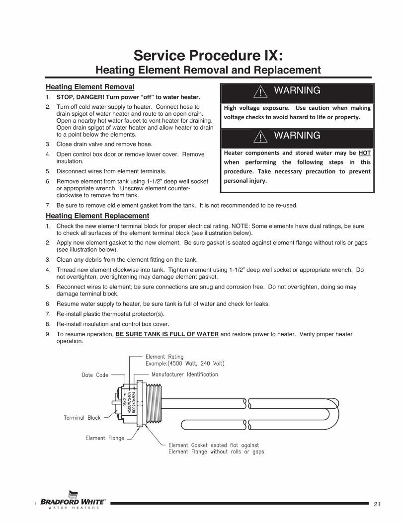
Service Procedure IX:Heating Element Removal and Replacement
Heating Element Removal 1. STOP, DANGER! Turn power “off” to water heater.2. Turn off cold water supply to heater. Connect hose to
drain spigot of water heater and route to an open drain. Open a nearby hot water faucet to vent heater for draining. Open drain spigot of water heater and allow heater to drain to a point below the elements.
3. Close drain valve and remove hose. 4. Open control box door or remove lower cover. Remove
insulation. 5. Disconnect wires from element terminals. 6. Remove element from tank using 1-1/2” deep well socket
or appropriate wrench. Unscrew element counter-clockwise to remove from tank.
7. Be sure to remove old element gasket from the tank. It is not recommended to be re-used. Heating Element Replacement 1. Check the new element terminal block for proper electrical rating. NOTE: Some elements have dual ratings, be sure
to check all surfaces of the element terminal block (see illustration below). 2. Apply new element gasket to the new element. Be sure gasket is seated against element flange without rolls or gaps
(see illustration below). 3. Clean any debris from the element fitting on the tank. 4. Thread new element clockwise into tank. Tighten element using 1-1/2” deep well socket or appropriate wrench. Do
not overtighten, overtightening may damage element gasket. 5. Reconnect wires to element; be sure connections are snug and corrosion free. Do not overtighten, doing so may
damage terminal block. 6. Resume water supply to heater, be sure tank is full of water and check for leaks. 7. Re-install plastic thermostat protector(s). 8. Re-install insulation and control box cover. 9. To resume operation, BE SURE TANK IS FULL OF WATER and restore power to heater. Verify proper heater
operation.
WARNINGHigh voltage exposure. Use caution when makingvoltage checks to avoid hazard to life or property.
WARNINGHeater components and stored water may be HOTwhen performing the following steps in thisprocedure. Take necessary precaution to preventpersonal injury.

22
22
Service Procedure X:Anode Inspection and Replacement
Anode Inspection and Replacement 1. STOP, DANGER! Turn power “off” to water heater.2. Turn off cold water supply to heater. Connect hose to
drain spigot of water heater and route to an open drain. Open a nearby hot water faucet to vent heater for draining. Open drain spigot of water heater and allow heater to drain to a point below the elements.
3. Close drain valve and remove hose. 4. Remove plastic anode access plugs at the anode
locations. 5. Remove Anode from the water heater (1-1/16” socket). 6. Visually inspect anode. Anode should show signs of
depletion, this is normal. If depletion is 1/2 of the original anode diameter (original diameter approximately 3/4"), replacement is recommended. If any of the steel core of the anode is exposed, replacement is recommended.
7. Upon completion of inspection or subsequent replacement, reinstall anode into hater. Resume water supply, refill heater with water and check for leaks.
8. To resume operation, BE SURE HEATER IS FULL OF WATER and turn power “ON” to water heater.
WARNINGHigh voltage exposure. Use caution when makingvoltage checks to avoid hazard to life or property.
WARNINGHeater components and stored water may be HOTwhen performing the following steps in thisprocedure. Take necessary precaution to preventpersonal injury.
23
23
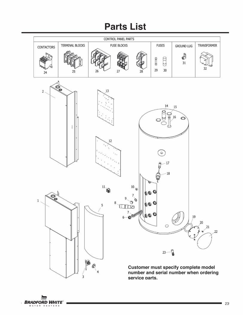
Parts List
Customer must specify complete model number and serial number when ordering service parts.

24
24
Parts List
Glossary of Terms
Term Definition Unit of Measure Voltage- Electrical Potential Volts Current- Rate of voltage flow Amperes (amp) Resistance- Ability of a device to dissipate power irreversibly Ohms Energy- Ability to do work kW/hr, Joule Power- Energy per unit of time Watts, kW, VA
One kilowatt (1kW) = 1,000 Watts = 3,412 BTU BTUH = British thermal units per hour DC = Direct Current PSI = Pounds per square inch AC=Alternating Current GPM = Gallons per minute Hz = Hertz GPH = Gallons per hour °F = Degrees Fahrenheit NPT = Nation pipe thread °C = Degrees Centigrade ASME = American Society of Mechanical Engineers
1 Large Control Box 17 ¾” NPT Nipple2 Small Control Box 18 Temperature and Pressure Relief Valve 3 Temperature Switch 19 Cleanout Ring4 Thermostat Dial 20 Cleanout Cover5 Element Insulation 21 Cleanout Screw6 Heating Element 22 Jacket Cleanout Cover7 Element Gasket 23 Drain Valve8 Inlet Diptube 24 Contactor9 Element Plug 25 Terminal Block10 ¾” NPT Plug 26 600V Fuse Block (3 Pole)11 Hi Limit Switch 27 Fuse Block (3 Pole)12 Large Control Panel 28 Fuse Block (1 Pole)13 Small Control Panel 29 Fuse “C” Class14 Outlet Nipple 30 Fuse “J” Class15 Anode Hole Plug 31 Ground Lug16 Anode 32 Transformer