CONTENTbqtinh/data/FEM.pdf · · 2013-01-25CONTENT A. Plane truss (2D ... is MATLAB. Specially,...
22
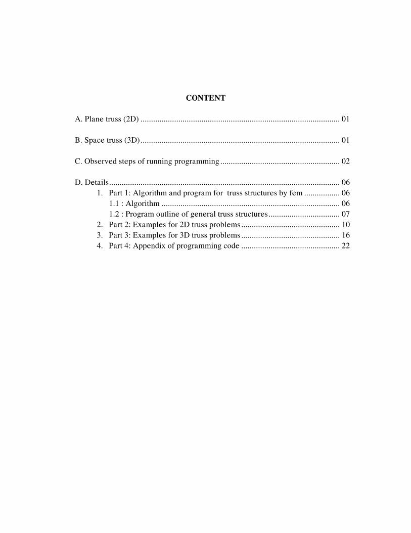
CONTENT A. Plane truss (2D) ............................................................................................... 01 B. Space truss (3D) ............................................................................................... 01 C. Observed steps of running programming ......................................................... 02 D. Details .............................................................................................................. 06 1. Part 1: Algorithm and program for truss structures by fem ................. 06 1.1 : Algorithm ..................................................................................... 06 1.2 : Program outline of general truss structures .................................. 07 2. Part 2: Examples for 2D truss problems ............................................... 10 3. Part 3: Examples for 3D truss problems ............................................... 16 4. Part 4: Appendix of programming code ............................................... 22
-
Upload
truongtruc -
Category
Documents
-
view
213 -
download
1
Transcript of CONTENTbqtinh/data/FEM.pdf · · 2013-01-25CONTENT A. Plane truss (2D ... is MATLAB. Specially,...
CONTENT
A. Plane truss (2D) ............................................................................................... 01 B. Space truss (3D)............................................................................................... 01 C. Observed steps of running programming......................................................... 02 D. Details.............................................................................................................. 06
1. Part 1: Algorithm and program for truss structures by fem ................. 06 1.1 : Algorithm ..................................................................................... 06 1.2 : Program outline of general truss structures.................................. 07
2. Part 2: Examples for 2D truss problems............................................... 10 3. Part 3: Examples for 3D truss problems............................................... 16 4. Part 4: Appendix of programming code ............................................... 22

EMMC9 EXERCISE 7: TRUSS STRUCTURES
EXERCISE 7: Write a computer code for modeling a plane truss structure with bars of constant section
and elastic modulus over the length. The code has then to be extended to allow the consideration of bars in a three-dimentional configuration. The bars only transmit axial force. On the chosen application examples, point out the bars in compression and those in tension.
This problem will be solved by finite element method, in which we using the laguage programming with a computer algebra system, is MATLAB. Specially, these problems could solve for all truss structures in either 2D or 3D. - Two dimensional bar element
- Three dimensional bar element
A. PLANE TRUSS (2D) The plane truss included m-files followed: 1. planetruss.m : main file 2. inputdata2d.m : input data, disconnection, localization and drawing geometric structure. 3. feeldof.m : index vector 4. Ke2d.m : Computation of element stiffness matrix 5. Feasmbl1.m : Assembly of global striffness matrix 6. Loadforce.m : Apply nodal forces 7. Feaplyc2.m : Apply boundary conditions 8. elstresses.m : Recovery internal force and stresses 9. drawdisplacement2d.m : The drawing of displacement plot
B. SPACE TRUSS (3D) From the code of 2D truss has then to be extended to 3D truss. The space truss included m-files followed: 1. spacetruss.m : main file 2. inputdata3d.m : input data , disconnection , localization and drawing geometric structure 3. feeldof.m : index vector 4. Ke3d.m : Computation of element stiffness matrix 5. Feasmbl1.m : Assembly of global striffness matrix 6. Loadforce3d.m : Apply nodal forces 7. Feaplyc2.m : Apply boundary conditions 8. elstresses3d : Recovery internal force and stresses 9. drawdisplacement3d : The drawing of displacement
1

EMMC9 EXERCISE 7: TRUSS STRUCTURES
C. OBSERVED STEPS OF RUNNING PROGRAMMING
1. Running Matlab (version 5.3), from menu file we set path folder program correct 2. From Command window of Matlab, we press keys either planetruss for 2D probems
or spacetruss for 3D problems. 3. Next, we ready input data from keyboard according to messages of program. A detail
description is in Example 1, we can input :
We input total number of elements
We input nodes coordinate from keyboard
2

EMMC9 EXERCISE 7: TRUSS STRUCTURES
4. Next, we input boundary conditions and loads follow :
We input loads
We input boundary conditions
3

EMMC9 EXERCISE 7: TRUSS STRUCTURES
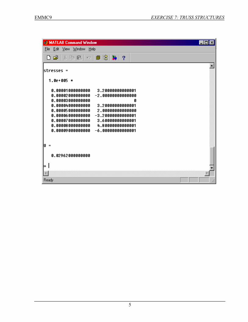
5. Finally, we have results : displacements, internal force, stresses and strain energy
Results of Interal force
Results of displacements
4
EMMC9 EXERCISE 7: TRUSS STRUCTURES
5
EMMC9 EXERCISE 7 : TRUSS STRUCTURES
D. DETAILS Part 1 : ALGORITHM AND PROGRAM FOR TRUSS STRUCTURES BY FEM
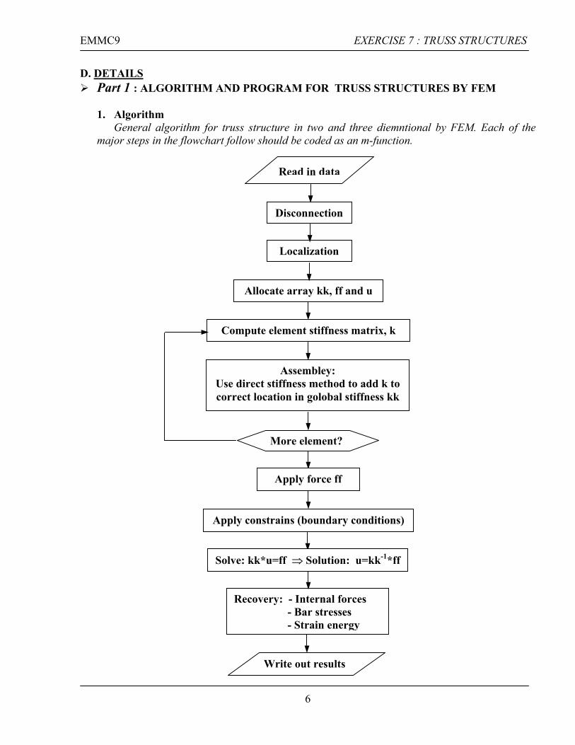
1. Algorithm
General algorithm for truss structure in two and three diemntional by FEM. Each of the major steps in the flowchart follow should be coded as an m-function.
Localization
Disconnection
Read in data
Solve: kk*u=ff ⇒ Solution: u=kk-1*ff
Write out results
Recovery: - Internal forces - Bar stresses - Strain energy
Apply constrains (boundary conditions)
Apply force ff
More element?
Assembley: Use direct stiffness method to add k to correct location in golobal stiffness kk
Compute element stiffness matrix, k
Allocate array kk, ff and u
6

EMMC9 EXERCISE 7 : TRUSS STRUCTURES
2. Program outline of general truss structures
Localization
Disconnection
Read in data %=========================================================== % INPUT DATA, DISCONNECTION & LOCALIZATION %=========================================================== nnode=input('THE TOTAL NUMBER OF NODES OF SYSTEM := '); [gcoord,nodes,nel,nnel,ndof,sdof,el,area]=inputdata2d(nnode); %===========================================================
Allocate array kk, ff and u %=========================================================== % INITIALIZATION TO ZEZO MATRIXS %=========================================================== % initialization to zero ff=zeros(sdof,1); % system force vector kk=zeros(sdof,sdof); % system stiffness vector index=zeros(nnel*ndof,1); % index vector elforce=zeros(nnel*ndof,1); % element force vector eldisp=zeros(nnel*ndof,1); % element nodal displacement vector k=zeros(nnel*ndof,nnel*ndof); % element stiffness vector stress=zeros(nel,1); % stress vector for every element
More element?
Assembley: Use direct stiffness method to add k to correct location in golobal stiffness kk
Compute element stiffness matrix, k %=========================================================== % THE ASSEMBLY OF GLOBAL STIFFNESS MATRIX %=========================================================== for iel=1:nel % loop for the total number of elements
7
EMMC9 EXERCISE 7 : TRUSS STRUCTURES
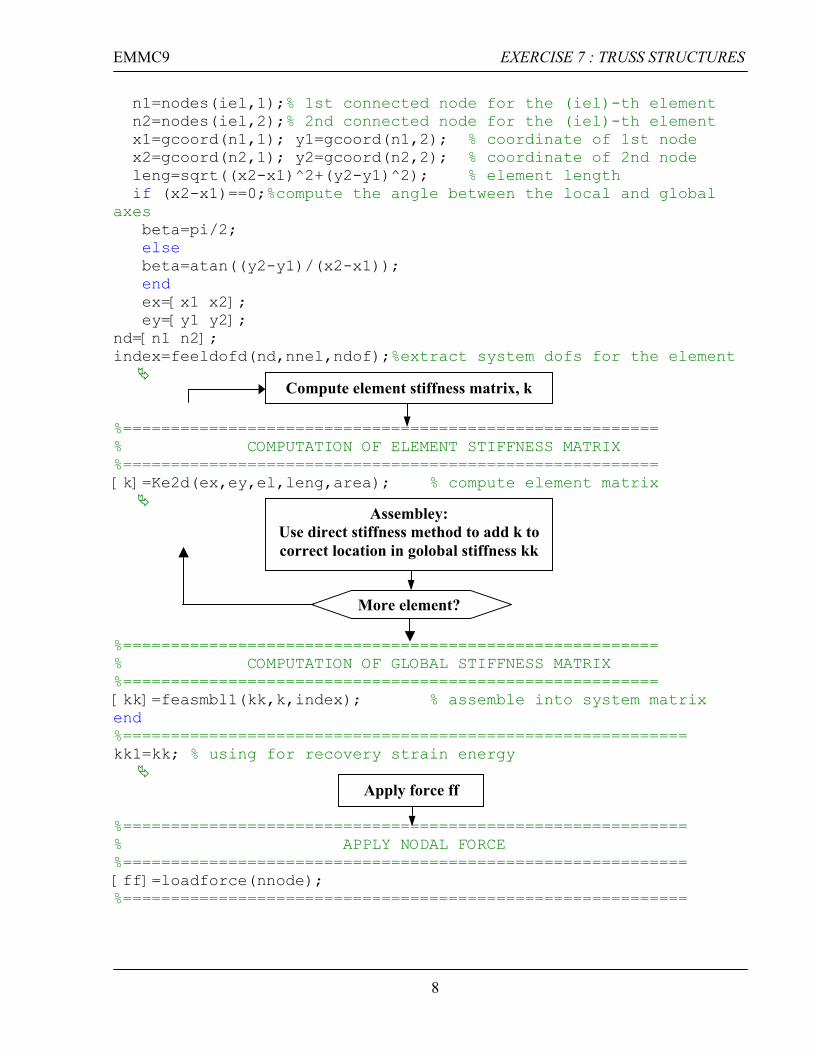
n1=nodes(iel,1);% 1st connected node for the (iel)-th element n2=nodes(iel,2);% 2nd connected node for the (iel)-th element x1=gcoord(n1,1); y1=gcoord(n1,2); % coordinate of 1st node x2=gcoord(n2,1); y2=gcoord(n2,2); % coordinate of 2nd node leng=sqrt((x2-x1)^2+(y2-y1)^2); % element length if (x2-x1)==0;%compute the angle between the local and global axes beta=pi/2; else beta=atan((y2-y1)/(x2-x1)); end ex=[x1 x2]; ey=[y1 y2]; nd=[n1 n2]; index=feeldofd(nd,nnel,ndof);%extract system dofs for the element
%========================================================
Compute element stiffness matrix, k
% COMPUTATION OF ELEMENT STIFFNESS MATRIX %======================================================== [k]=Ke2d(ex,ey,el,leng,area); % compute element matrix
%========================================================
More element?
Assembley: Use direct stiffness method to add k to correct location in golobal stiffness kk
% COMPUTATION OF GLOBAL STIFFNESS MATRIX %======================================================== [kk]=feasmbl1(kk,k,index); % assemble into system matrix end %=========================================================== kk1=kk; % using for recovery strain energy
%===========================================================
Apply force ff
% APPLY NODAL FORCE %=========================================================== [ff]=loadforce(nnode); %===========================================================
8

EMMC9 EXERCISE 7 : TRUSS STRUCTURES
Apply constrains (boundary conditions) %=================================================== % APPLY BOUNDARY CONDITIONS %=================================================== [kk,ff]=feaplyc2(kk,ff,bcdof,bcval); %===================================================
%===================================================
Solve: kk*u=ff ⇒ Solution: u=kk-1*ff
% THE DISPLAYCEMENT SOLUTIONS %=================================================== disp=kk\ff; % solve matrix equation to find nodal displacements num=1:1:sdof; displace=[num’ disp] % print nodal displacements %========================================================== % THE DISPLACEMENT PLOT %========================================================== [drawdisp]=drawdisplacement2d(nel,nodes,gcoord,disp) %==========================================================
Write out results
Recovery: - Internal forces - Bar stresses - Strain energy
%========================================================== % RECOVERY INTERNAL FORCES & STRESSES %========================================================= [stress,nel,internalforce]=elstresses(nel,nodes,gcoord,nnel,ndof,area,el,eldisp,elforce,disp); internalforce; numm=1:1:nel; N=[numm' internalforce] % print internal forces stress=stress'; numm=1:1:nel; stresses=[numm' stress] % print stresses %========================================================= % RECOVERY STRAIN ENERGY %========================================================= U=0.5*disp'*kk1*disp ; % print strain energy %========================================================= % END
9

EMMC9 EXERCISE 7 : TRUSS STRUCTURES
Part 2: EXAMPLES FOR 2D TRUSS PROBLEMS: (Running file: planetruss.m ) Example 1: The simple plane truss has geometric structure followed
4m 4m 1200 N
4m
400 N
3 m
- The simple plane truss has 6 nodes and 9 elements. It is fixed at node 1 and on rollers at node 6. The apply loads above pictrue.
- Elastic modulus for all elements: 200e-9 N/m2 - Cross-section area for all elements: 0.0025 m - After running a planetruss program, it is disconnected and is showing follow :
The disconnection plot of plane truss structure
10

EMMC9 EXERCISE 7 : TRUSS STRUCTURES
- Solution: displacements of 6 nodes of simple plane truss
Degree of freedom
Displacements 10-4 (m)
1 0 2 0 3 0.0640000000000 4 -0.3140000000000 5 0.1730000000000 6 -0.3140000000000 7 0.1280000000000 8 -0.4573333333333 9 0.1090000000000 10 -0.403333333333 11 0.224000000000 12 0
: along to x direction : along to y direction
The displacement plot of plane truss under loads effect in above geometric structure
11

EMMC9 EXERCISE 7 : TRUSS STRUCTURES
- Recovery : internal force and stresses
Elements Internal force: 103 (N) Stress : 105 (N/m2) 1 0.800000000000 3.200000000000 2 -0.500000000000 -1.999999999999 3 0 0 4 0.800000000000 3.200000000000 5 0.500000000000 2.000000000000 6 -0.800000000000 -3.199999999999 7 0.900000000000 3.600000000000 8 1.200000000000 4.799999999999 9 -1.500000000000 -5.900000000000
- Recovery: Strain energy corresponding with apply loads at 4 and 5 nodes and has value
are Fx(4)=400 N and Fy(5)=1200 N, respectively. We obtained strain energy U U= 0.02962000000000
Comment : - From stresses value, we look at elements are compressed (negative value ): 2, 6 and 9. - Else, we also have got rest elements are tensioned (positive value) - When we increase loads along to y direction, then strain energy in system also are
increased, in which we could show under diagram.
Strain energy of plane truss
0
0.01
0.02
0.03
0.04
0.05
0 500 1000 1500 2000
loads
Stra
in e
nerg
y
Strain energy
Loads (N) 300 600 900 1200 1500 Strain energy
0.00344 0.008837778 0.017564444 0.02962 0.04500444
12

EMMC9 EXERCISE 7 : TRUSS STRUCTURES
Example 2 : The analysis of the 6-bay bridge truss problem
- This example 2 is got from the chapter 22 of Introduction to finite element method book (lecture notes). But where all elements has same a cross-section areas.
- This bridge truss has 12 nodes and 21 elements. It is fixed at node 1 and on rollers at node 12. The apply loads follow pictrue The truss structure showing supports and apply loads follow :
16 10 10 10 10
Span : 6 bays * 10=60
5 8 9
- Elastic modulus for all elements: 200e-9 N/m2 - Cross-section area for all elements :0.0025 m - Finite element idealization as pin-jointed truss - After running a planetruss program, it is disconnected and is showing follow :
The disconnection plot of plane truss structure
- Solution: displacements of 12 nodes of bridge truss
Degree of freedom Displacement 10-4 m 1 0 2 0 3 0.0447010959 4 -0.1207071434 5 0.0112000000 6 -0.1217071434 7 0.0448023868 8 -0.1646678607
: along to x direction : along to y direction
13

EMMC9 EXERCISE 7 : TRUSS STRUCTURES
9 0.0224000000 10 -0.1661478607 11 0.0339000000 12 -0.1774484847 13 0.0339000000 14 -0.1796084847 15 0.0229976132 16 -0.1646678607 17 0.0454000000 18 -0.1661478607 19 0.0230989041 20 -0.1207071434 21 0.0566000000 22 -0.1217071434 23 0.0678000000 24 0
The displacement plot of example 2
14

EMMC9 EXERCISE 7 : TRUSS STRUCTURES
- Recovery : internal force and stresses Element Internal force (N) Stress 104 (N/m2) 1 55.99999999999884 2.23999999999995 2 55.99999999999884 2.23999999999995 3 57.49999999999888 2.29999999999996 4 57.49999999999889 2.29999999999996 5 55.99999999999869 2.23999999999995 6 55.99999999999881 2.23999999999995 7 -62.60990336999309 -2.50439613479972 8 -60.03176242623474 -2.40127049704939 9 -60.29925372672417 -2.41197014906897 10 -60.29925372672423 -2.41197014906897 11 -60.03176242623442 -2.40127049704938 12 -62.60990336999268 -2.50439613479971 13 10.00000000000000 0.40000000000000 14 9.24999999999977 0.36999999999999 15 12.00000000000000 0.48000000000000 16 9.24999999999977 0.36999999999999 17 10.00000000000023 0.40000000000001 18 1.67705098312484 0.06708203932499 19 3.20156211871626 0.12806248474865 20 3.20156211871650 0.12806248474866 21 1.67705098312500 0.06708203932500
- Recovery: Strain energy corresponding with apply loads all along y directive at 3, 5, 7, 9
and 11, has values are: 10,10,16,10 and 10, respectively. We obtained strain energy U U= 4.315417919416590e-004
Comment: - From stresses value, we look at elements are compressed (negative value ) 7, 8, 9, 10,
11 and 12. - Else, we also have got rest elements are tensioned (positive value) - Similar, such above Example 1, when we increase loads along to y direction, then strain
energy in system also are increased.
15
EMMC9 EXERCISE 7 : TRUSS STRUCTURES
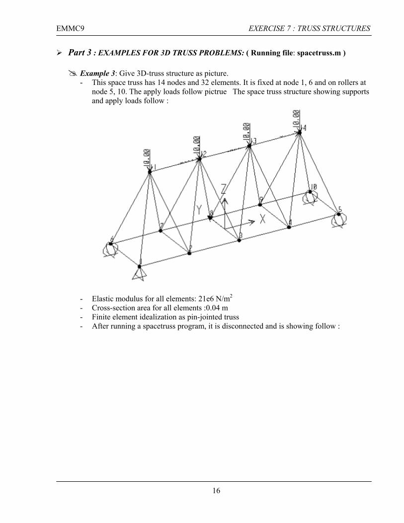
Part 3 : EXAMPLES FOR 3D TRUSS PROBLEMS: ( Running file: spacetruss.m )
Example 3: Give 3D-truss structure as picture. - This space truss has 14 nodes and 32 elements. It is fixed at node 1, 6 and on rollers at
node 5, 10. The apply loads follow pictrue The space truss structure showing supports and apply loads follow :
- Elastic modulus for all elements: 21e6 N/m2 - Cross-section area for all elements :0.04 m - Finite element idealization as pin-jointed truss - After running a spacetruss program, it is disconnected and is showing follow :
16
EMMC9 EXERCISE 7 : TRUSS STRUCTURES
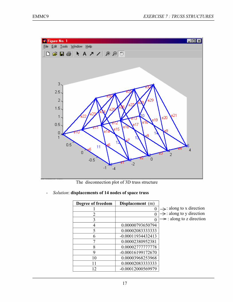
The disconnection plot of 3D truss structure
- Solution: displacements of 14 nodes of space truss
Degree of freedom Displacement (m) 1 0 2 0 3 0 4 0.00000793650794 5 0.00002083333333 6 -0.00011934432413 7 0.00002380952381 8 0.00002777777778 9 -0.00016199172670 10 0.00003968253968 11 0.00002083333333 12 -0.00012000569979
: along to x direction : along to y direction : along to z direction
17
EMMC9 EXERCISE 7 : TRUSS STRUCTURES
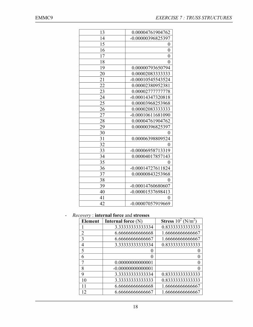
13 0.00004761904762 14 -0.00000396825397 15 0 16 0 17 0 18 0 19 0.00000793650794 20 0.00002083333333 21 -0.00010545543524 22 0.00002380952381 23 0.00002777777778 24 -0.00014347320818 25 0.00003968253968 26 0.00002083333333 27 -0.00010611681090 28 0.00004761904762 29 0.00000396825397 30 0 31 0.00006398809524 32 0 33 -0.00006958713319 34 0.00004017857143 35 0 36 -0.00014727611824 37 0.00000843253968 38 0 39 -0.00014760680607 40 -0.00001537698413 41 0 42 -0.00007057919669
- Recovery : internal force and stresses
Element Internal force (N) Stress 102 (N/m2) 1 3.33333333333334 0.83333333333333 2 6.66666666666668 1.66666666666667 3 6.66666666666667 1.66666666666667 4 3.33333333333334 0.83333333333333 5 0 0 6 0 0 7 0.00000000000001 0 8 -0.00000000000001 0 9 3.33333333333334 0.83333333333333 10 3.33333333333333 0.83333333333333 11 6.66666666666668 1.66666666666667 12 6.66666666666667 1.66666666666667
18

EMMC9 EXERCISE 7 : TRUSS STRUCTURES
13 3.33333333333334 0.83333333333333 14 -11.05541596785133 -2.76385399196283 15 5.52770798392567 1.38192699598142 16 -5.52770798392568 -1.38192699598142 17 -0.00000000000001 0 18 -0.00000000000001 0 19 -5.52770798392567 -1.38192699598142 20 5.52770798392567 1.38192699598142 21 -11.05541596785134 -2.76385399196283 22 -11.05541596785135 -2.76385399196284 23 5.52770798392569 1.38192699598142 24 -5.52770798392569 -1.38192699598142 25 -0.00000000000001 0 26 -0.00000000000001 0 27 -5.52770798392567 -1.38192699598142 28 5.52770798392567 1.38192699598142 29 -11.05541596785134 -2.76385399196284 30 -10.00000000000001 -2.50000000000000 31 -13.33333333333335 -3.33333333333334 32 -10.00000000000001 -2.50000000000000
- Recovery: Strain energy corresponding with apply loads all along z directive at 11, 12,
13 and 14, all has values are: 10 N, respectively. We obtained strain energy U
U= 0.00217524627092
Comment: - From stresses value, we look at elements are compressed (negative value ) : 14, 16, 19,
21, 22, 24, 27, 29, 30, 31 and 32 - Else, we also have got rest elements are tensioned (positive value) - Similar, such above Example 1, when we increase loads along to y direction, then strain
energy in system also are increased.
19
EMMC9 EXERCISE 7 : TRUSS STRUCTURES
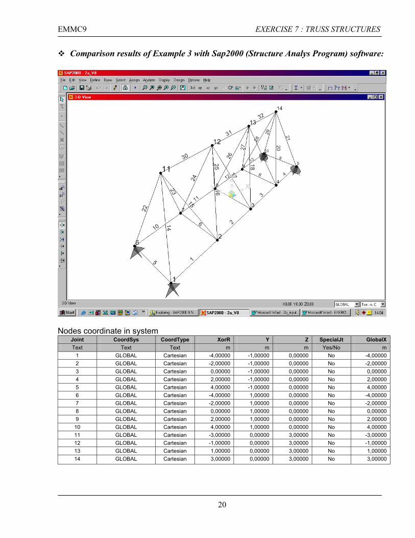
Comparison results of Example 3 with Sap2000 (Structure Analys Program) software:
Nodes coordinate in system
Joint CoordSys CoordType XorR Y Z SpecialJt GlobalX Text Text Text m m m Yes/No m
1 GLOBAL Cartesian -4,00000 -1,00000 0,00000 No -4,00000 2 GLOBAL Cartesian -2,00000 -1,00000 0,00000 No -2,00000 3 GLOBAL Cartesian 0,00000 -1,00000 0,00000 No 0,00000 4 GLOBAL Cartesian 2,00000 -1,00000 0,00000 No 2,00000 5 GLOBAL Cartesian 4,00000 -1,00000 0,00000 No 4,00000 6 GLOBAL Cartesian -4,00000 1,00000 0,00000 No -4,00000 7 GLOBAL Cartesian -2,00000 1,00000 0,00000 No -2,00000 8 GLOBAL Cartesian 0,00000 1,00000 0,00000 No 0,00000 9 GLOBAL Cartesian 2,00000 1,00000 0,00000 No 2,00000
10 GLOBAL Cartesian 4,00000 1,00000 0,00000 No 4,00000 11 GLOBAL Cartesian -3,00000 0,00000 3,00000 No -3,00000 12 GLOBAL Cartesian -1,00000 0,00000 3,00000 No -1,00000 13 GLOBAL Cartesian 1,00000 0,00000 3,00000 No 1,00000 14 GLOBAL Cartesian 3,00000 0,00000 3,00000 No 3,00000
20

EMMC9 EXERCISE 7 : TRUSS STRUCTURES
The comparison of Internal force : Results are correctly(the same)
Elements Internal Forces in Sap2000 software
Internal Forces in Matlab (spacetruss program)
1 3,3333 3.33333333333334 2 6,6667 6.66666666666668 3 6,6667 6.66666666666667 4 3,3333 3.33333333333334 5 0,0000 0 6 0,0000 0 7 2,665E-15 0.00000000000001 8 -7,216E-16 -0.00000000000001 9 3,3333 3.33333333333334
10 3,3333 3.33333333333333 11 6,6667 6.66666666666668 12 6,6667 6.66666666666667 13 3,3333 3.33333333333334 14 -11,0554 -11.05541596785133 15 5,5277 5.52770798392567 16 -5,5277 -5.52770798392568 17 -7,105E-15 -0.00000000000001 18 -7,105E-15 -0.00000000000001 19 -5,5277 -5.52770798392567 20 5,5277 5.52770798392567 21 -11,0554 -11.05541596785134 22 -11,0554 -11.05541596785135 23 5,5277 5.52770798392569 24 -5,5277 -5.52770798392569 25 7,105E-15 -0.00000000000001 26 -7,105E-15 -0.00000000000001 27 -5,5277 -5.52770798392567 28 5,5277 5.52770798392567 29 -11,0554 -11.05541596785134 30 -10,0000 -10.00000000000001 31 -13,3333 -13.33333333333335 32 -10,0000 -10.00000000000001
21