BPMN BY EXAMPLE - Orbus Software · BPMN by Example: An Introduction to the Business Process...
59
BPMN by Example An Introduction to the Business Process Modeling Notation v2.0 David B Jones and Roderick J Brown www.orbussoftware.com [email protected] +44 (0) 870 991 1851
Transcript of BPMN BY EXAMPLE - Orbus Software · BPMN by Example: An Introduction to the Business Process...

BPMN by Example
An Introduction to the Business Process
Modeling Notation v2.0
David B Jones and Roderick J Brown
www.orbussoftware.com
+44 (0) 870 991 1851

BPMN by Example: An Introduction to the Business Process Modeling Notation v2.0
Table of Contents
Page 1
Table of Contents
Table of Contents ....................................................................................................................... 1
1 Introducing BPMN ............................................................................................................... 8
1.1 Background .................................................................................................................. 8
1.2 History of BPMN .......................................................................................................... 9
1.3 Why would I use BPMN? ............................................................................................. 9
1.4 What you should use BPMN for? .............................................................................. 10
1.5 How you should use BPMN? ..................................................................................... 10
1.5.1 Overview of BPMN ............................................................................................. 11
1.6 Overview of BPMN Components ............................................................................... 11
1.7 Overview of BPMN Process Types and Categories .................................................... 12
1.8 Overview of Core BPMN Elements ............................................................................ 12
1.8.1 Case Study .......................................................................................................... 15
1.9 Overview .................................................................................................................... 15
1.10 Applying the Learning using the Case Study .......................................................... 15
1.10.1 Understanding Types of BPMN Diagrams .......................................................... 16
1.11 Overview of BPMN Process Models and Diagram Types ....................................... 16
1.12 BPMN Process Model Types .................................................................................. 16
1.12.1 Descriptive Process Models ............................................................................... 16
1.12.2 Analytic Process Models ..................................................................................... 16
1.13 BPMN Diagram Types ............................................................................................ 17
1.13.1 Collaboration Diagram ....................................................................................... 17
1.13.2 Process Diagram ................................................................................................. 18
1.14 Process Model Types versus Process Diagram Types ............................................ 18
1.15 Best Practice Recommendations ........................................................................... 19
1.16 Case Study Process Models and Process Diagrams ............................................... 19
1.16.1 Understanding the types of Swim Lanes ............................................................ 20
BPMN by Example: An Introduction to the Business Process Modeling Notation v2.0
Table of Contents
Page 2
1.17 Overview ................................................................................................................ 20
1.18 Pools ....................................................................................................................... 20
1.19 Lanes ...................................................................................................................... 21
1.20 Best Practice Recommendations ........................................................................... 21
1.21 Case Study Implications ......................................................................................... 22
2 Overview of Flow Objects .................................................................................................. 23
2.1 Overview of Flow Objects .......................................................................................... 23
2.2 Overview of Event Types ........................................................................................... 23
2.3 Overview of Activity Types ........................................................................................ 23
2.4 Overview of Gateway Types ...................................................................................... 24
2.4.1 Understanding Event Types ............................................................................... 25
2.5 Start Event Triggers ................................................................................................... 25
2.6 Intermediate Events Triggers .................................................................................... 25
2.7 Intermediate Boundary Events Triggers .................................................................... 26
2.8 End Events Triggers.................................................................................................... 27
2.9 Best Practice Recommendations ............................................................................... 28
2.9.1 Recommendations for Event Naming ................................................................ 28
2.9.2 Recommendations for Start Events ................................................................... 28
2.9.3 Recommendations for Intermediate Events ...................................................... 29
2.9.4 Recommendations for Boundary Intermediate Events ..................................... 29
2.9.5 Recommendations for End Events ..................................................................... 29
2.10 Case Study Implications ......................................................................................... 29
2.10.1 Start Events usage in Case Study........................................................................ 29
2.10.2 Intermediate Events usage in Case Study .......................................................... 29
2.10.3 Boundary Intermediate Events usage in Case Study ......................................... 30
2.10.4 End Events usage in Case Study ......................................................................... 30
3 Understanding the types of Activity .................................................................................. 31
BPMN by Example: An Introduction to the Business Process Modeling Notation v2.0
Table of Contents
Page 3
3.1 Tasks .......................................................................................................................... 31
3.2 Sub-Processes ............................................................................................................ 32
3.3 Additional forms of Activity ....................................................................................... 32
3.4 Best Practice Recommendations ............................................................................... 33
3.4.1 Background ......................................................................................................... 33
3.4.2 Recommendations for Activity Naming ............................................................. 33
3.4.3 Recommendations for Tasks .............................................................................. 34
3.4.4 Recommendations for Sub-Processes ................................................................ 34
3.5 Case Study Implications ............................................................................................. 34
3.5.1 Using Tasks in the Case Study ............................................................................ 34
3.5.2 Using Sub-Processes in the Case Study .............................................................. 35
4 Understanding the Types of Gateway ............................................................................... 36
4.1 Exclusive Gateway ..................................................................................................... 36
4.2 Inclusive Gateway ...................................................................................................... 36
4.3 Parallel Gateway ........................................................................................................ 36
4.4 Event Based Gateway ................................................................................................ 37
4.5 Best Practice Recommendations ............................................................................... 37
4.5.1 Recommendations for Exclusive Gateways ....................................................... 37
4.5.2 Recommendations for Inclusive Gateways ........................................................ 37
4.5.3 Recommendations for Parallel Gateways .......................................................... 37
4.5.4 Recommendations for Event Based Gateways .................................................. 38
4.6 Case Study Implications ............................................................................................. 38
4.6.1 Using Exclusive Gateways in the Case Study ...................................................... 38
4.6.2 Using Inclusive Gateways in the Case Study ...................................................... 38
4.6.3 Using Parallel Gateways in the Case Study ........................................................ 38
4.6.4 Using Event Based Gateways in the Case Study ................................................ 38
5 Understanding the Types of Data ...................................................................................... 39
BPMN by Example: An Introduction to the Business Process Modeling Notation v2.0
Table of Contents
Page 4
5.1 Overview of Data ....................................................................................................... 39
5.2 Data Objects .............................................................................................................. 39
5.3 Data Stores ................................................................................................................ 40
5.4 Messages ................................................................................................................... 40
5.5 Best Practice Recommendations ............................................................................... 40
5.6 Case Study Implications ............................................................................................. 41
6 Understanding the types of Artefacts ............................................................................... 42
6.1 Overview of Artefacts ................................................................................................ 42
6.2 Group Objects ............................................................................................................ 42
6.3 Annotations ............................................................................................................... 42
6.4 Best Practice Recommendations ............................................................................... 43
6.5 Case Study Implications ............................................................................................. 43
7 Understanding the types of Connecting Objects .............................................................. 44
7.1 Overview of Types of Connecting Objects................................................................. 44
7.2 Sequence Flow Connecting Objects .......................................................................... 44
7.3 Message Flow Connecting Objects ............................................................................ 45
7.4 Association ................................................................................................................. 45
7.5 Best Practice Recommendations ............................................................................... 45
7.5.1 Recommendations for Sequence Flow Connecting Objects .............................. 45
7.5.2 Recommendations for Message Flow Connecting Objects ............................... 46
7.5.3 Recommendations for Associations ................................................................... 46
7.6 Case Study Implications ............................................................................................. 46
7.6.1 Implications for Sequence Flow Connecting Objects ......................................... 46
7.6.2 Implications for Message Flow Connecting Objects .......................................... 46
7.6.3 Implications for Associations ............................................................................. 46
8 Bringing it all together ....................................................................................................... 47
8.1 Overview .................................................................................................................... 47
BPMN by Example: An Introduction to the Business Process Modeling Notation v2.0
Table of Contents
Page 5
8.2 Define Case Study Scope ........................................................................................... 47
8.3 Identify Case Study Processes ................................................................................... 47
8.4 Prepare high level Case Study Process View ............................................................. 48
8.5 Analyze the Contents of each of the Case Study Processes ...................................... 49
8.5.1 Overview ............................................................................................................ 49
8.5.2 Analyze Contents of Capture Beverage Order ................................................... 49
8.5.3 Analyze Contents of Prepare Beverages ............................................................ 49
8.5.4 Analyze Contents of Retrieve More Supplies ..................................................... 49
8.6 Document each of the Case Study Processes ............................................................ 49
8.6.1 Overview ............................................................................................................ 49
8.7 Details of BPMN Core Elements ................................................................................ 50
8.7.1 Capture Beverage Order .................................................................................... 53
8.7.2 Prepare Beverage Order..................................................................................... 53
8.7.3 Retrieve More Supplies ...................................................................................... 54
9 Appendices ........................................................................................................................ 54
9.1 BPMN Elements for Descriptive Type Process Models ............................................. 55
9.2 BPMN Elements for Analytic Type Process Models .................................................. 56
9.3 Bibliography ............................................................................................................... 58
BPMN by Example: An Introduction to the Business Process Modeling Notation v2.0
Table of Contents
Page 6
Table of Figures and Tables
Figure 1: Example BPMN Model ................................................................................................ 8
Figure 3: A representation of the BPMN Core and Layer Structure ........................................ 11
Table 1: Core BPMN Elements ................................................................................................. 12
Figure 4: Example of Collaboration Diagram ........................................................................... 17
Figure 5: Example Process Diagram ......................................................................................... 18
Figure 6: BPMN Symbol for a Pool ........................................................................................... 20
Figure 7: Example of the BPMN Symbols used for Lanes and Sub-Lanes ................................ 21
Figure 8: Recommended Swim Lanes for Case Study .............................................................. 22
Figure 9: BPMN Symbol for a Start Event ................................................................................ 25
Figure 10: BPMN Symbol for an Intermediate Event ............................................................... 25
Figure 11: BPMN Symbol for a Message Interrupting Intermediate Boundary Event ............ 26
Figure 12: BPMN Symbol for a Message Non-Interrupting Intermediate Boundary Event .... 27
Figure 13: BPMN Symbol for an End Event .............................................................................. 27
Figure 14: Recommended approach for naming Events .......................................................... 28
Table 2: BPMN Symbols for Tasks ............................................................................................ 31
Table 3: Task types of Activities ............................................................................................... 31
Table 4: Types of Sub-Process Activities .................................................................................. 32
Table 5: Activity Markers .......................................................................................................... 33
Figure 15: Recommended approach for naming Activities ...................................................... 34
Figure 16: BPMN Symbol for an Exclusive Gateway ................................................................ 36
Figure 17: BPMN Symbol for an Inclusive Gateway ................................................................. 36
Figure 18: BPMN Symbol for a Parallel Gateway ..................................................................... 37
Figure 19: BPMN Symbol for an Event Based Gateway ........................................................... 37
Figure 20: BPMN Symbol for a Data Object ............................................................................. 39
Figure 21: BPMN Symbol for Data Object Collection ............................................................... 39
Figure 22: BPMN Symbol for Data Object with Input and Output attributes .......................... 39
Figure 23: BPMN Symbol for Data Store .................................................................................. 40
Figure 24: BPMN Symbol for Message ..................................................................................... 40
Figure 25: BPMN Symbol for Group Object ............................................................................. 42
Figure 26: BPMN Symbol for of Annotation Object ................................................................. 43
Figure 27: BPMN Symbol for Sequence Flow ........................................................................... 44
Figure 28: BPMN Symbols for Default and Conditional Sequence Flows ................................ 44

BPMN by Example: An Introduction to the Business Process Modeling Notation v2.0
Table of Contents
Page 7
Figure 29: BPMN Symbol for Message Flow ............................................................................ 45
Figure 30: BPMN Symbol for Association ................................................................................. 45
Figure 31: BPMN Symbol for Directional Association .............................................................. 45
Figure 32: Collaboration Diagram - Fulfil Beverage Order ....................................................... 48
Table 6: BPMN Diagram Types ................................................................................................. 50
Table 7: Swim Lane Objects ..................................................................................................... 50
Table 8: Flow Objects ............................................................................................................... 51
Table 9: Artefact Objects .......................................................................................................... 51
Table 10: Connecting Objects .................................................................................................. 52
Figure 33: Process Diagram - Capture Beverage Order ........................................................... 53
Figure 34: Process Diagram - Prepare Beverage order ............................................................ 53
Figure 35: Process Diagram for Retrieve More Supplies ......................................................... 54
Table 11: BPMN Elements for Descriptive type Process Model .............................................. 55
Table 12: BPMN Elements for Analytic type Process Model ................................................... 56
BPMN by Example: An Introduction to the Business Process Modeling Notation v2.0
Introducing BPMN
Page 8
1 Introducing BPMN
1.1 Background
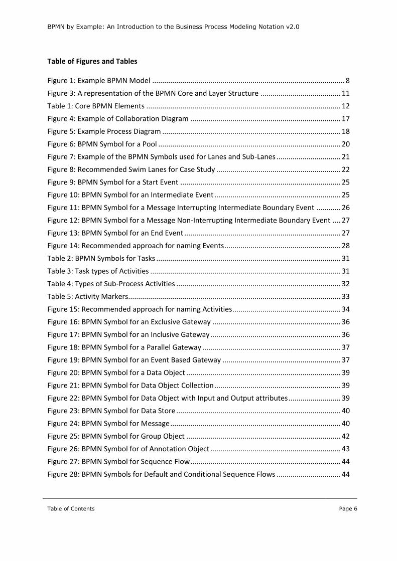
Much has been written about the importance of documenting processes. You have decided to, or
have been asked to document some processes within your organization. You have also heard that
BPMN (Business Process Model and Notation) is the best way of documenting processes.
Figure 1: Example BPMN Model
However, you are unsure as to the facts of:
Whether you should use BPMN;
Why you should use BPMN;
What you should use BPMN for; and
How you should use BPMN?
The search for answers to these questions starts by searching for “BPMN” on Google, with
approximately 2,000,000 results returned. So, where do you start?
The large number of the results shows the level of interest in the subject and the website of the
Object Management Group (www.OMG.org) is a good place to start. The OMG created BPMN and
are responsible for managing the development of the standard.
Opening the BPMN v2.0 specification, you discover it is 550 pages long! If you were really
adventurous and managed to get to Chapter 7 or beyond, you would discover there are more than
100 objects in the complete palette for BPMN. However, approximately 50% of these or around 50 to
60 are required to simply document processes, as the remainder relate to being able to define
Business Processes that can be made executable.
Quickly moving to open the next document (BPMN 2.0 by Example: non-normative OMG document
with BPMN 2.0 examples), you find that this is a more manageable 47 page document. After scanning
this document, however, you are even more confused, with all this technical jargon and mentions of
a funny language called XML.

BPMN by Example: An Introduction to the Business Process Modeling Notation v2.0
Introducing BPMN
Page 9
1.2 History of BPMN
The need for a common process diagramming standard in the late 1990’s was a key driver in a
number of different initiatives beginning in the early 2000’s. One of these initiatives was the Business
Process Management Initiative (BPMI). It was under the management of the BPMI, that the Business
Motivation Model (BMM) and Business Process Model and Notation (BPMN) came into existence.
BPMN V1.0 was first published in 2004. Shortly after, in 2005, the BPMI merged with a larger
initiative group, the Object Management Group (OMG). Since 2005, OMG has continued to develop
BPMN and a range of other potentially helpful standards, such as the Semantics of Business
Vocabulary and Business Rules (SBVR) and Business Process Maturity Model (BPMM).
The latest finalized version of BPMN is Version 2.0, released in January 2011, which followed on from
BPMN 1.2.
Although there are reasonably significant changes between BPMN 1.2 and 2.0, the majority of the
changes relate to the various technical aspects of BPMN, which are not covered in this document.
1.3 Why would I use BPMN?
The importance of documenting Business Processes has been covered in Management articles and
texts. To illustrate the importance of documenting your business processes, virtually all Process
Improvement approaches, such as Six Sigma and Lean, start with documenting the business
processes being studied. However, that obviously begs the question, “How do I document business
processes?”
BPMN has become widely adopted, as the means of graphically documenting business processes
across the globe. For example, many government and corporate organizations now mandate the use
of BPMN in the documenting of their Business Processes.
Because of the wide adoption of BPMN as a business process modeling standard, there are an
increasing range of tools to:
Assist in setting standard times or targets for your business processes;
Help manage the execution of your business processes;
Collect data from your business processes to help identify issues that need to be improved; and
Assist in analyzing your processes to identify and test (by simulation) possible improvements.
BPMN by Example: An Introduction to the Business Process Modeling Notation v2.0
Introducing BPMN
Page 10
The growing take up of BPMN has also been driven by adoption of Business Process Management
(BPM) supported by the rising use of Business Process Management Suites (BPMS), many of which
use BPMN as their means of describing business processes to enable execution of these processes.
1.4 What you should use BPMN for?
BPMN should only be used to document the details of how a process operates. BPMN is a visual
representation of a process that shows:
Who is involved in the process and their interactions; and
The flow of a business process from activity to activity.
Although BPMN can be used to breakdown a process into increasing levels of detail, it is generally
not seen or used as a means of showing process decomposition at high levels.
1.5 How you should use BPMN?
This document focuses on how to use BPMN in documenting your processes by showing what each
of the various symbols mean and the context in which they should be used using examples.
As briefly mentioned earlier, you do not need to learn the complete range of BPMN 2.0 objects to be
able to successfully apply BPMN. In fact, it is best to learn and apply BPMN to document your
Business Processes in a layered approach.
Using this approach, it is only necessary to learn and apply around 25 BPMN Objects and Symbols to
build quite reasonably detailed representations of your Business Process using BPMN.
Only around another 25 to 30 BPMN Objects and Symbols are needed to increase the level of detail
required to cope with about 90% to 95% of all Business Processes.
Well, let’s get started.

BPMN by Example: An Introduction to the Business Process Modeling Notation v2.0
Overview of BPMN
Page 11
2 Overview of BPMN
2.1 Overview of BPMN Components
The BPMN 2.0 Specification has been created to support many different points of view, for example:
Business Users wanting to document their processes;
IT Professionals wanting to turn the above processes into executable process applications; and
Software Vendors wanting to develop Business Process Modeling tools or BPMS products.
With so many competing interests to satisfy during the development of BPMN 2.0, it is no surprise
that the final specification ended up resembling one designed by a committee, i.e. lacking a clarity of
purpose, frequently verbose (as witnessed by its 500 plus pages) and unsure of who is the primary
audience.
This is best illustrated by looking at the Core and Layer Structure of BPMN shown in the Specification:
Figure 2: A representation of the BPMN Core and Layer Structurei
BPMN by Example: An Introduction to the Business Process Modeling Notation v2.0
Overview of BPMN
Page 12
2.2 Overview of BPMN Process Types and Categories
The BPMN 2.0 Specification defines three “sub-classes” (or types) of Process Models:
Descriptive;
Analytic; and
Common Executable.
The Descriptive type of Process Models document Business Processes at an overview or high-level
(i.e. minimal details) and use a limited sub-set of BPMN’s visible elements and attributes.
The Analytic type of Process Models provide more detail than the Descriptive type with an expanded
sub-set of BPMN’s visible elements and attributes, about half the complete set.
The Common Executable type of Process Models focus on the detail needed to explain how Business
Processes can be executed and use the complete set of BPMN’s visible Elements and attributes.
The Specification also explains that to conform to BPMN 2.0, Process Models must, at a minimum,
allow Business Processes to be documented using Core BPMN Elements (see the following later
section) in the form of 3 different types of diagrams;
Collaboration diagrams (see 4.2);
Process diagrams (see 4.3.2); and
Conversation diagrams (not covered any further within this document).
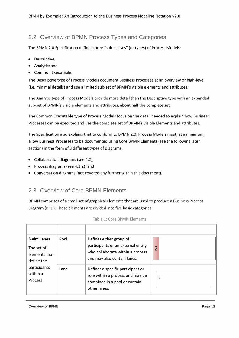
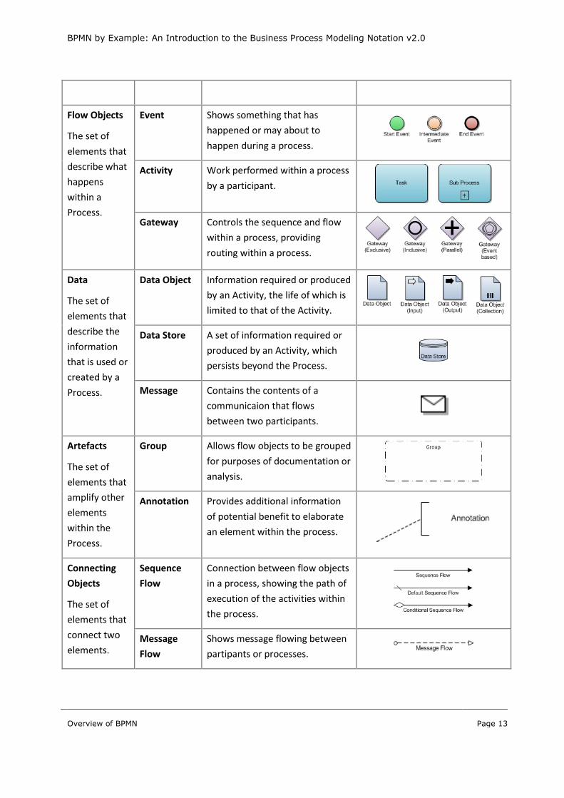
2.3 Overview of Core BPMN Elements
BPMN comprises of a small set of graphical elements that are used to produce a Business Process
Diagram (BPD). These elements are divided into five basic categories:
Table 1: Core BPMN Elements
Category Elements Description Symbol
Swim Lanes
The set of
elements that
define the
participants
within a
Process.
Pool Defines either group of
participants or an external entity
who collaborate within a process
and may also contain lanes.
Lane Defines a specific participant or
role within a process and may be
contained in a pool or contain
other lanes.
BPMN by Example: An Introduction to the Business Process Modeling Notation v2.0
Overview of BPMN
Page 13
Category Elements Description Symbol
Flow Objects
The set of
elements that
describe what
happens
within a
Process.
Event Shows something that has
happened or may about to
happen during a process.
Activity Work performed within a process
by a participant.
Gateway Controls the sequence and flow
within a process, providing
routing within a process.
Data
The set of
elements that
describe the
information
that is used or
created by a
Process.
Data Object Information required or produced
by an Activity, the life of which is
limited to that of the Activity.
Data Store A set of information required or
produced by an Activity, which
persists beyond the Process.
Message Contains the contents of a
communicaion that flows
between two participants.
Artefacts
The set of
elements that
amplify other
elements
within the
Process.
Group Allows flow objects to be grouped
for purposes of documentation or
analysis.
Annotation Provides additional information
of potential benefit to elaborate
an element within the process.
Connecting
Objects
The set of
elements that
connect two
elements.
Sequence
Flow
Connection between flow objects
in a process, showing the path of
execution of the activities within
the process.
Message
Flow
Shows message flowing between
partipants or processes.

BPMN by Example: An Introduction to the Business Process Modeling Notation v2.0
Overview of BPMN
Page 14
Category Elements Description Symbol
Association Links Data Items to Flow Object
and shows direction(s).

BPMN by Example: An Introduction to the Business Process Modeling Notation v2.0
Case Study
Page 15
3 Case Study
3.1 Overview
The case study is based on the simple concept of ordering, making and providing Coffee or Tea in a
typical Café. For the purposes of attempting not to over complicate the Case Study, the only drinks
that can be ordered are:
Coffee
o Cappuccino
o Café Latte
o Espresso
Tea
o English Breakfast
o Earl Grey
For the purposes of the Case Study, it is assumed that the processes to order, prepare and deliver the
hot beverage are similar to those in any large coffee chain. The processes include:
Orders and cash are taken by the Serving Attendant / Cashier from the Customer;
Orders taken by the Serving Attendant / Cashier are passed to a Barista automatically and shown
on a screen for fulfilment by a Barista;
There are separate processes for preparing tea and coffee;
Completed orders are provided to the Customer by the Barista; and
The Barista can also request additional milk and coffee beans to be obtained from the store room
by the kitchen hands or additional stock to be ordered by the Café Manager.
The Customer is able to select the Sugar or Sweetener of their choice from a serving bar, located at
the point where Customers receive their beverage.
3.2 Applying the Learning using the Case Study
Each of the following sections of the document details the key aspects of BPMN, covering:
What it means;
How to use it; and
Suggested best practices to use.
At the end of these sections, each key aspect will be put into context by describing how a component
of the Case Study can be documented.
BPMN by Example: An Introduction to the Business Process Modeling Notation v2.0
Understanding Types of BPMN Diagrams
Page 16
4 Understanding Types of BPMN Diagrams
4.1 Overview of BPMN Process Models and Diagram Types
As previously covered, the BPMN 2.0 Specification defines three “sub-classes” (or categories) of
Process Models, namely:
Descriptive Process Models;
Analytic Process Models; and
Common Executable Process Models.
The BPMN Specification explains that BPMN 2.0 aims to cover three basic models of Business
Processes:
Public Processes, which are more commonly known as Collaboration Diagrams;
Private Processes, which are more simply called Process Diagrams; and
Choreographies, which are more commonly called Choreography Diagrams.
A fourth BPMN diagram type, Conversation Diagrams, is also defined by the BPMN 2.0 Specification.
4.2 BPMN Process Model Types
4.2.1 Descriptive Process Models
Because Descriptive Process Models are used to document Business Processes at a high-level,
Descriptive Process Models are essentially the starting point for documenting Business Processes.
The primary purpose of Descriptive Process Models is to show the overall flow of a Business Process,
covering the details of the process steps undertaken and how the different Parties interact within it.
Not surprisingly, the limited nature of the sub-set of BPMN visual elements and attributes of
Descriptive Process Models make it the ideal starting point for learning how to document your
Business Processes using BPMN. In fact, it is possible to adequately document an Organization’s
entire set of Business Processes using only Descriptive Process Models.
You could even decide not to progress any further. However, the restrictive sub-set of BPMN visual
elements and attributes means that the level of detail that can be captured is limited. This can cause
problems when you are trying to adequately cover details of complex or intricate processes.
4.2.2 Analytic Process Models
As described above, Analytical Process Models allow more detail to be added in documenting your
Business Process by extending the sub-set of BPMN visual elements and attributes that are contained
within Descriptive Process Models.

BPMN by Example: An Introduction to the Business Process Modeling Notation v2.0
Understanding Types of BPMN Diagrams
Page 17
Analytical Process Models are typically the key to capturing the more complex or intricate details of
Business Processes. The additions to the Descriptive Process Model sub-set of the BPMN visual
elements and attributes effectively double the available set of visual elements and attributes.
4.3 BPMN Diagram Types
4.3.1 Collaboration Diagram
A Collaboration Diagram documents the interactions between a process and either other processes
or a Party.
A Party is either external to the organization or a different area within the organization and can be
either responsible for the process or provide necessary information for the process. A Party is
represented by a Pool.
Figure 3: Example of Collaboration Diagram
A Collaboration Diagram provides the “canvas” to document your business processes at the level
which shows the interaction between all the participants and the processes. However, it is not the
only form of Diagram you use to document your Processes. Rather, its primary purpose is to show
how the key external and internal Parties are involved in the processes being documented.

BPMN by Example: An Introduction to the Business Process Modeling Notation v2.0
Understanding Types of BPMN Diagrams
Page 18
Consequently, the primary use of a Collaboration Diagram is to show the collaboration of Parties with
the higher level Processes.
4.3.2 Process Diagram
A Process Diagram documents processes that are internal to an organization or a specific area within
the organization. Consequently, a Process Diagram represents the processes contained with a Single
Pool. However it may contain none, one, or more than one Lane in a Pool or a Pool implied by one
inherited from a Collaboration Diagram.
As illustrated below, the use of no Lanes can provide a simple means of documenting a Process
where the role executing the Process is shown on the Collaboration Diagram above it.
Figure 4: Example Process Diagram
4.4 Process Model Types versus Process Diagram Types
As we outlined earlier, the primary purpose of Descriptive Process Models is to show the overall flow
of a Business Process, covering the details of the process steps undertaken and how the different
Parties interact within it.
Consequently, a Descriptive Process Model is typically the type of Process Model used to document
Collaboration Diagrams. So, it is probably no surprise that Analytic Process Models are also typically
the type of Process Models used to document Process Diagrams.
BPMN by Example: An Introduction to the Business Process Modeling Notation v2.0
Understanding Types of BPMN Diagrams
Page 19
However, it is not necessarily that simple. For example, you may wish to just use Descriptive Models,
or to also use the Analytic Process Model type for documenting Collaboration Diagrams.
The basis for deciding which of the Process Model types to use will depend on the level of detail you
want to capture and also the number of levels of detail you choose to adopt in documenting your
Organization’s Business Processes.
4.5 Best Practice Recommendations
For simple or straight forward processes, the typical choices would be to use:
A single level of Collaboration Diagrams using a Descriptive type of Process Model; plus
Each Process defined on the Collaboration Diagrams documented with a Process Diagram using an
Analytic type of Process Model.
For less straight forward or complicated processes, the typical choices would be to use:
Two levels of Collaboration Diagrams, with the top most level using a Descriptive type of Process
Model type and the lower level documenting each of the processes identified and documented on
the top level using an Analytic type of Process Model; plus
Each of the Processes defined on the lower level Collaboration Diagrams documented with a
Process Diagram using an Analytic type of Process Model.
4.6 Case Study Process Models and Process Diagrams
To document the Case Study:
A single Collaboration Diagram, using the Descriptive type of Process Model, will be used to
document the overall Process; and
Multiple Process Diagrams, using the Analytic type of Process Model, will be used to document
each of the Processes required to prepare the Coffee and Tea Beverages.

BPMN by Example: An Introduction to the Business Process Modeling Notation v2.0
Understanding the types of Swim Lanes
Page 20
5 Understanding the types of Swim Lanes
5.1 Overview
Swim Lanes are used to represent the various Parties and Roles involved in a Process. They are
represented on the Collaboration and Process Diagrams by Pools and Lanes.
The analogy of a Swimming Pool demonstrates each Pool is independent of another, and can also
contain one or more Lanes. This is extended to show a Process may flow from one Lane to another
within a single Pool, but it is not allowed to flow across Pools, although information (in the form of
messages) is allowed to flow from one Pool to another.
Consequently, a key issue in understanding what to represent with a Pool or a Lane is to understand
the relationships between the Parties and Roles being documented and the degree of influence the
management of one Party or Role has over another Party or Role.
5.2 Pools
As summarised in 2.3, a Pool represents a Party involved in a process. The Pool often represents a
Party external to the organization being modeled. However, a Pool can also be used to represent
different areas within the organization. Under some circumstances, a Pool can also be used to show
a Process. This should be seen as the exception rather than the norm.
The BPMN symbol for a Pool provides the “canvas” that is used to contain all the BPMN Flow
Elements that are used to define the details of the Process contained within it.
Figure 5: BPMN Symbol for a Pool
Pools can be documented and shown as either a “White Box” or “Black Box”:
A “White Box” Pool contains all the details of a Process contained within it; whereas
A “Black Box Pool” does not, i.e. the details are shown to the reader in a “White Box” Pool but
hidden from the reader in a “Black Box” Pool.

BPMN by Example: An Introduction to the Business Process Modeling Notation v2.0
Understanding the types of Swim Lanes
Page 21
5.3 Lanes
As also summarised in 2.3, a Lane represents a position or role position within the Party defined by
the Pool in which it contains. Lanes can also be further divided into sub-Lanes.
Similar to that for a Pool, the BPMN symbol for a Lane provides the “canvas” that can be used to
contain the BPMN Flow Elements used to define the details of the Process contained within it.
Figure 6: Example of the BPMN Symbols used for Lanes and Sub-Lanes
5.4 Best Practice Recommendations
It is recommended that all Parties involved in the Business Process but who are external to the
Organization, such as a Customer or Supplier, should be represented using Black Box Pools.
The only reason to vary this would be where it is necessary or highly desirable to document the
actual steps being undertaken within the Pool. This may, for example, be appropriate if you are
attempting to agree a new process with a Supplier.
Parties internal to an Organization should be documented using one of more White Box Pools. The
deciding factor on how many White Box Pools to include will be based on how many areas within the
Organization participate but are operated and managed independently of other areas. For example,
in the Organization that sells Coffee Beans to the Café in our Case Study, the Sales area of the
Organization will be documented using a different Pool to that which sources the Coffee Beans or
ships the Coffee Beans to Cafés.
Lanes within the White Pools should represent the different Participants who undertake the various
steps within it. A Lane can be further divided into Sub-Lanes to represent different roles that a
Participant undertakes. However, this should be used sparingly to illustrate specific key role
variations of importance.
BPMN by Example: An Introduction to the Business Process Modeling Notation v2.0
Understanding the types of Swim Lanes
Page 22
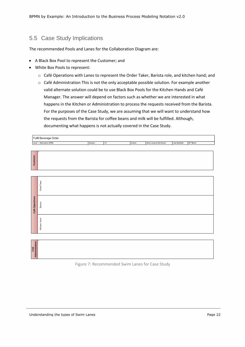
5.5 Case Study Implications
The recommended Pools and Lanes for the Collaboration Diagram are:
A Black Box Pool to represent the Customer; and
White Box Pools to represent:
o Café Operations with Lanes to represent the Order Taker, Barista role, and kitchen hand; and
o Café Administration This is not the only acceptable possible solution. For example another
valid alternate solution could be to use Black Box Pools for the Kitchen Hands and Café
Manager. The answer will depend on factors such as whether we are interested in what
happens in the Kitchen or Administration to process the requests received from the Barista.
For the purposes of the Case Study, we are assuming that we will want to understand how
the requests from the Barista for coffee beans and milk will be fulfilled. Although,
documenting what happens is not actually covered in the Case Study.
Figure 7: Recommended Swim Lanes for Case Study
BPMN by Example: An Introduction to the Business Process Modeling Notation v2.0
Overview of Flow Objects
Page 23
6 Overview of Flow Objects
6.1 Overview of Flow Objects
There is a set of 3 Flow Objects, namely:
Events – represent something that “happens” during the course of a Process;
Activities – represent work undertaken within a Business Process; and
Gateways – control the flow within a Business Process.
6.2 Overview of Event Types
As summarised in 2.3, an Event is something that “happens” during the course of a Process and these
Events affect the flow of the model and usually have a cause (trigger) or an impact (result).
Events are circles with open centres to allow internal markers that help to differentiate different
triggers or results. There are three basic types of events:
Start Events occur at the start of a process and cause the initiation of a process;
Intermediate Events – which can occur anywhere between the start and end events within the
process; and
End Events – these can only occur at the end of a process and describe the results that are leading
to the exit of the process.
There is also a special form of Intermediate Events that are attached to the boundary of an Activity.
These are called Intermediate Boundary Events.
6.3 Overview of Activity Types
As also summarised in 2.3, an Activity is used to represent work undertaken within a Business
Process. Activities are used to represent the points in a Process flow where work is actually
performed.
An Activity is represented, within a Process, as either:
An Atomic Activity – which is the lowest level (or simplest) form of an Activity, i.e. not able to be
broken down further; or
A non-Atomic Activity – which is the highest level (or compound) form of an Activity, i.e. able to
be broken down further.
BPMN by Example: An Introduction to the Business Process Modeling Notation v2.0
Overview of Flow Objects
Page 24
The Atomic form of an Activity is called a Task and the non-atomic form of an Activity is called a Sub-
Process.
An Activity doesn’t have a single graphical object; rather it is a set of graphical objects. Both Tasks
and Sub-Processes can also be used as a Call Activity, which allows a specific instance of a Tasks or
Sub-Process to be re-used across multiple Processes.
6.4 Overview of Gateway Types
As outlined in 2.3, Gateways are used to control how Sequence Flows interact as they converge and
diverge within a Process. If the sequence flow does not need to be controlled and the process is
flowing from one activity to the next, then a Gateway is not needed.
There are five types of Gateways;
Exclusive Gateway – which represents a branching point in the process that requires one and
only one of the possible paths being chosen from the available options based on the
evaluation of an Expression;
Inclusive Gateway – which represents a branching point in the process that allows one or
more (i.e. multiple) of the possible paths being chosen from the available options based on
the evaluation of an Expression;
Parallel Gateway – which represents a branching point in the process where all of the paths
in the process must be followed;
Event Based Gateway – which represents a branching point in the Process where the
alternative paths that follow the Gateway are based on Events (defined after the Event Based
Gateway) that can occur, rather than the evaluation of an Expression; and
Complex Gateway – which provides the ability to support complex merging, and branching
behaviour that is not captured by other Gateways.
Note:
A Gateway does not undertake any processing to evaluate expressions or events. Rather, it should be
simply seen as the routing mechanism. Evaluation of any expression, for which the Gateway is to
undertake the routing, should be undertaken in the previous Activity.

BPMN by Example: An Introduction to the Business Process Modeling Notation v2.0
Understanding Event Types
Page 25
7 Understanding Event Types
7.1 Start Event Triggers
As previously outlined in 6.2, a Start Event can only occur at the start of a process. It is the means by
which a Process is started (hence the name) or initiated. A Start Event is graphically represented in
BPMN as a circle with a single thin outside border, as shown below:
Figure 8: BPMN Symbol for a Start Event
A start event is typically triggered by:
None – which has no specific defined trigger;
Message – is triggered by the arrival of a message from another process or participant;
Timer – is triggered by the arrival of a specific date (and time) or after a cycle, e.g. 9am on
Monday or 1st of the Month; and
Conditional – is triggered when a specified condition is reached, e.g. credit limit is exceeded;
Escalation – occurs when escalation is identified and has been triggered;
Error – is triggered when some form of error state has been previously identified and triggered;
and
Signal – is triggered by the arrival of a signal broadcast by another activity or process.
7.2 Intermediate Events Triggers
As previously indicated in 6.2, an Intermediate Event occurs anywhere within a Process between the
start and end events. An Intermediate Event is graphically represented in BPMN as a circle with twin
thin outside borders, as shown below:
Figure 9: BPMN Symbol for an Intermediate Event
An intermediate event is typically triggered or impacted by:
None – which has no specific defined trigger;
Message – by the arrival of a message from another process or participant (a Catch event) or
sending of a message to another process or participant (a Throw event);
BPMN by Example: An Introduction to the Business Process Modeling Notation v2.0
Understanding Event Types
Page 26
Timer – is triggered by the need to wait for a specific date (and time), cycle or delay, e.g. Monday
at 9am, End of the Month or 12 hours;
Escalation – occurs when escalation is identified and needs to be triggered;
Compensation - occurs when a process has finished, but that compensation is needed;
Conditional – is triggered when a specified condition is reached, e.g. credit limit is exceeded;
Link – is used to connect two parts of the process, usually across page boundaries or to remove
the need for crossed lines; and
Signal – is triggered by the arrival of a signal broadcast by another activity or process.
A number of the trigger types of Intermediate Events occur in two forms:
Throwing – which occurs when the Intermediate Event is causing something to happen, for
example a ‘throwing’ Intermediate Message Event represents the sending (or throwing) of a
message; and
Catching – which occurs when the Intermediate Event is listening and waiting for something to
happen, for a catching Intermediate Message Event represents the receiving (or catching) of a
message.
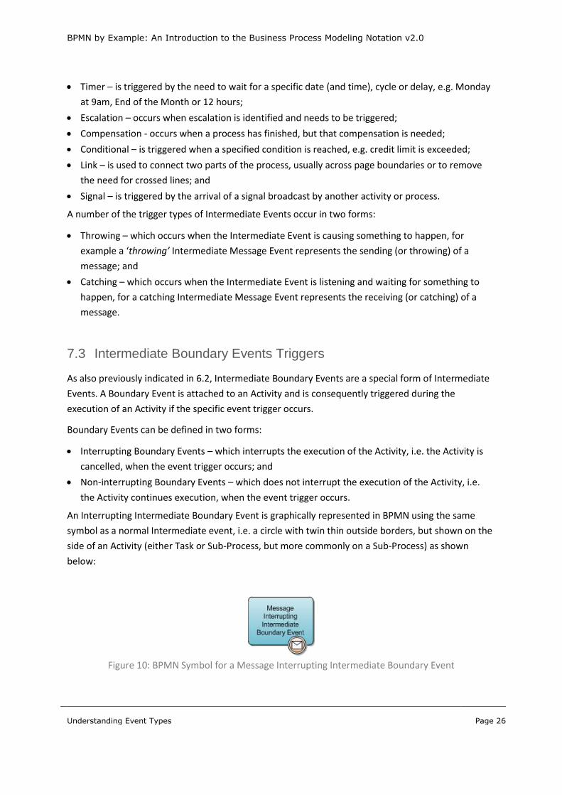
7.3 Intermediate Boundary Events Triggers
As also previously indicated in 6.2, Intermediate Boundary Events are a special form of Intermediate
Events. A Boundary Event is attached to an Activity and is consequently triggered during the
execution of an Activity if the specific event trigger occurs.
Boundary Events can be defined in two forms:
Interrupting Boundary Events – which interrupts the execution of the Activity, i.e. the Activity is
cancelled, when the event trigger occurs; and
Non-interrupting Boundary Events – which does not interrupt the execution of the Activity, i.e.
the Activity continues execution, when the event trigger occurs.
An Interrupting Intermediate Boundary Event is graphically represented in BPMN using the same
symbol as a normal Intermediate event, i.e. a circle with twin thin outside borders, but shown on the
side of an Activity (either Task or Sub-Process, but more commonly on a Sub-Process) as shown
below:
Figure 10: BPMN Symbol for a Message Interrupting Intermediate Boundary Event

BPMN by Example: An Introduction to the Business Process Modeling Notation v2.0
Understanding Event Types
Page 27
A Non-Interrupting Intermediate Boundary Event is graphically represented in BPMN using the same
symbol as a normal Intermediate event, i.e. a circle with twin thin outside borders, but shown on the
side of an Activity (either Task or Sub-Process, but more commonly on a Sub-Process) as shown
below:
Figure 11: BPMN Symbol for a Message Non-Interrupting Intermediate Boundary Event
The set of Boundary Event used in preparing Analytic type of Process Models are:
Message Intermediate Boundary Event (both Interrupting and Non-Interrupting);
Timer Intermediate Boundary Event (both Interrupting and Non-Interrupting);
Error Intermediate Boundary Event (Interrupting only);
Escalation Intermediate Boundary Event (Non-Interrupting only);
Signal Intermediate Boundary Event (both Interrupting and Non-Interrupting); and
Conditional Intermediate Boundary Event (both Interrupting and Non-Interrupting).
7.4 End Events Triggers
As also previously explained in 6.2, an End Event can only occur at the end of a process and is used to
define the exit point of a process and be the trigger for why the process ended. An End Event is
graphically represented in BPMN as a circle with either a single (or twin) thick outside borders, as
shown below:
Figure 12: BPMN Symbol for an End Event
An end event is typically triggered or impacted by:
None – which has no specific defined trigger;
Message – is triggered by the sending of a message to another process or participant;
Escalation – occurs when escalation is identified and needs to be triggered;
Compensation - occurs when a process has finished, and compensation is necessary;
Conditional – is triggered when a specified condition is reached, e.g. credit limit is exceeded;

BPMN by Example: An Introduction to the Business Process Modeling Notation v2.0
Understanding Event Types
Page 28
Error – is impacted when some form of error state is identified and a named Error should be
generated and triggered; and
Terminate – indicates that all Activities in the Process should be immediately ended;
7.5 Best Practice Recommendations
7.5.1 Recommendations for Event Naming
Events should be named using a <Qualifier> <Data Object> <Verb> approach. The Verb is usually
derived from the preceding or following action to be undertaken, taking the past tense or future
tense of the Verb used.
For example:
Beverage Order captured;
Beverage Order prepared;
Supplies retrieved; and
More Supplies needed.
Data Object names should contain words that provide specific and useful to describe the Data
Object.
It is important to avoid ambiguity so your readers can understand the Event and its trigger.
Figure 13: Recommended approach for naming Events
7.5.2 Recommendations for Start Events
The most commonly used trigger types for Start Events are the None, Message and Timer. However,
there are also occasions when the Error, Escalation and Conditional trigger are not only useful but
appropriate.
Qu
alif
ier Additional term
(consisting of one or more words) to assist in clarifying or amplifying the Data Object.
For example:
- Beverage
- Existing
- Credit card
Dat
a O
bje
ct The data on which the
process will primarily operate
For example:
- Order
- Account
- Payment
Ve
rb Describes when the
event has occurred or is scheduled to occur.
For example:
- Captured
- Prepared
- Recorded
BPMN by Example: An Introduction to the Business Process Modeling Notation v2.0
Understanding Event Types
Page 29
7.5.3 Recommendations for Intermediate Events
The None and Message and Timer triggers are again the most commonly used triggers when
documenting processes, although there are occasions when the Escalation, Compensation,
Conditional and Error can be useful. The Link type of an Intermediate Event is a special form of
Intermediate Event that allows linking between pages.
7.5.4 Recommendations for Boundary Intermediate Events
Knowing when to make use of Boundary Intermediate Events is difficult. The common uses for
Boundary intermediate Events are to handle Error and Escalation triggers within Activities, i.e. Sub-
Processes or Tasks.
Note: It is more likely that Boundary Intermediate Events will be used on Sub-Processes than Tasks,
as they are used as a means of catching specific event triggers during the execution of a Sub-Process.
7.5.5 Recommendations for End Events
The None and Message triggers are the commonly used triggers when documenting processes,
although there are occasions when the Escalation, Conditional, Error and Terminate can be useful.
7.6 Case Study Implications
7.6.1 Start Events usage in Case Study
Each Collaboration and Process diagram needs to begin with Start Events. For example, in the Case
Study:
“Fulfil Beverage Order” begins with Start Message Event “Beverage Order Received”; and
Prepare Beverages begins with None Start Event, Beverage Order Placed.
7.6.2 Intermediate Events usage in Case Study
There are three Intermediate Events used in the Case Study.
The first two of these are contained in “Fulfil Beverage Order”:
“order captured”, a Message Intermediate Event, is between “Capture Beverage order” and
“Prepare Beverage Order” sub-processes and is used to handle the Order Receipt and any change
to the customer and pass the order to the Barista; and
“supplies top-up needed”, a None Intermediate Event, is between “Prepare Beverages Order” and
“Retrieve More Supplies” Sub-Processes and is used to indicate a possible break in execution
between the Barista (requesting the replenishing of their supplies) and the Kitchen Hand
(retrieving and storing the additional supplies).
BPMN by Example: An Introduction to the Business Process Modeling Notation v2.0
Understanding Event Types
Page 30
A None Intermediate Event called “Beverages Made”, the remaining Intermediate Event used in the
Case Study, is used in “Prepare Beverage Order” to handle “beverage prepared” End Event, one of
the End Events in the Expanded Sub-Process.
7.6.3 Boundary Intermediate Events usage in Case Study
The Case Study uses several Boundary Intermediate Events.
As explained previously, Boundary Intermediate Events do have their uses and are an effective way
of handling events such as an Error or the need for Escalation. However, their use needs careful
consideration and application.
The Case Study uses Boundary Intermediate events in:
“Prepare Beverage Order” process to handle the escalation of when the Barista identifies that the
Coffee and Tea supplies need to be topped up; and
“Retrieve More Supplies” process to handle the escalation of when the Kitchen Hand identifies
that the Coffee and Tea Supplies need to be re-ordered by the Café Administration.
7.6.4 End Events usage in Case Study
Every process needs to have at least one End Event, just like Start Events. For example, in the Case
Study:
“Fulfil Beverage Order” ends with the End Events:
o None End Event “Order Completed”,
o None End Event “Supplies Retrieved”, and
o Message End Event “More Supplies Needed”;
“Capture Beverage Order” ends with the None End Event “Order Settled”;
“Prepare Beverage Order” ends with the End Events:
o None End Event “Supplies Needed”, and
o Message End Event “Beverage Order Prepared”.

BPMN by Example: An Introduction to the Business Process Modeling Notation v2.0
Understanding the types of Activity
Page 31
8 Understanding the types of Activity
8.1 Tasks
As explained previously, a Task is the atomic form of Activity and occurs within the overall flow of a
Process. Tasks are used when the work in the Process cannot be broken down to any finer level of
detail and generally, an end-user and/or application is used to represent the work performed by the
Task when it is executed.
Tasks can be used in one of two forms:
Table 2: BPMN Symbols for Tasks
Type of
Sub-Process
Description BPMN Symbol
Task
(Standard form)
A Task shares the same basic outline shape in as the Sub-
Process, which is a rectangle with rounded corners with a single
thin line
Call Activity Task When a Task is being used in its Call Activity form, i.e. as a re-
usable Task used across many Processes, the thin line is
changed to a thick line
In addition to the standard form of a Task, Tasks can also be divided into a number of sub-types.
These sub-types are used to identify specific details of who the Task is performed by or how the Task
is performed. For example, in Descriptive and Analytic types of Process Model, the following sub-
types of Tasks are defined:
Table 3: Task types of Activities
Sub-type Description BPMN Symbol
Service A Service Task is where the Task is being by a service, i.e. some form
of automation, e.g. a Web service or an automated application
User A User Task is a “workflow” Task performed by a person with the
assistance of an application and is scheduled through a task list
manager of some sort
Send A Send Task is designed to send a Message to an external Participant
of the process
BPMN by Example: An Introduction to the Business Process Modeling Notation v2.0
Understanding the types of Activity
Page 32
Receive A Receive Task is designed to receive a Message from an external
Participant
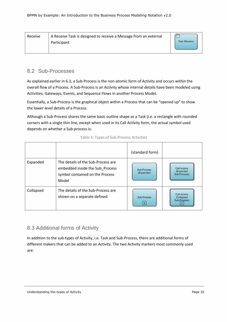
8.2 Sub-Processes
As explained earlier in 6.3, a Sub-Process is the non-atomic form of Activity and occurs within the
overall flow of a Process. A Sub-Process is an Activity whose internal details have been modeled using
Activities, Gateways, Events, and Sequence Flows in another Process Model.
Essentially, a Sub-Process is the graphical object within a Process that can be “opened up” to show
the lower-level details of a Process.
Although a Sub-Process shares the same basic outline shape as a Task (i.e. a rectangle with rounded
corners with a single thin line, except when used in its Call Activity form, the actual symbol used
depends on whether a Sub-process is:
Table 4: Types of Sub-Process Activities
Type of
Sub-Process
Description BPMN Symbol
(standard form)
BPMN Symbol (Call
Activity Form)
Expanded The details of the Sub-Process are
embedded inside the Sub_Process
symbol contained on the Process
Model
Collapsed The details of the Sub-Process are
shown on a separate defined
8.3 Additional forms of Activity
In addition to the sub-types of Activity, i.e. Task and Sub-Process, there are additional forms of
different makers that can be added to an Activity. The two Activity markers most commonly used
are:
BPMN by Example: An Introduction to the Business Process Modeling Notation v2.0
Understanding the types of Activity
Page 33
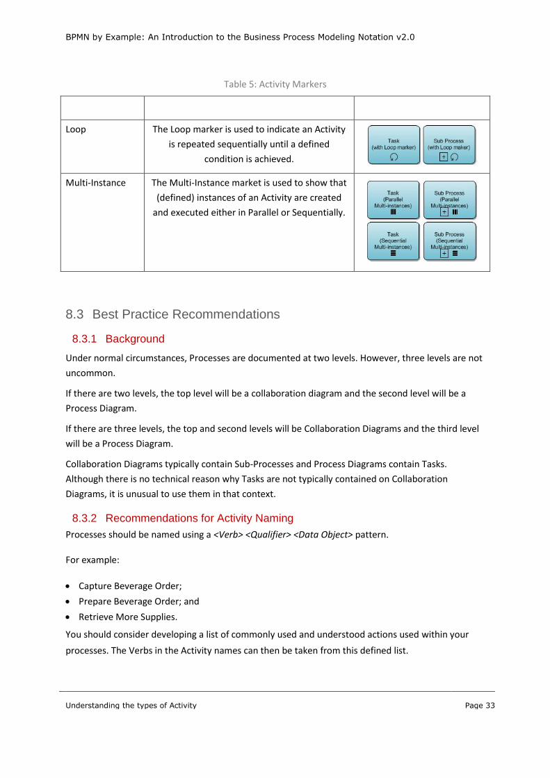
Table 5: Activity Markers
Activity Marker Description BPMN Symbol
Loop The Loop marker is used to indicate an Activity
is repeated sequentially until a defined
condition is achieved.
Multi-Instance The Multi-Instance market is used to show that
(defined) instances of an Activity are created
and executed either in Parallel or Sequentially.
8.3 Best Practice Recommendations
8.3.1 Background
Under normal circumstances, Processes are documented at two levels. However, three levels are not
uncommon.
If there are two levels, the top level will be a collaboration diagram and the second level will be a
Process Diagram.
If there are three levels, the top and second levels will be Collaboration Diagrams and the third level
will be a Process Diagram.
Collaboration Diagrams typically contain Sub-Processes and Process Diagrams contain Tasks.
Although there is no technical reason why Tasks are not typically contained on Collaboration
Diagrams, it is unusual to use them in that context.
8.3.2 Recommendations for Activity Naming
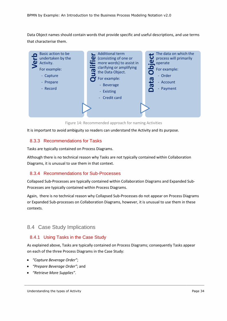
Processes should be named using a <Verb> <Qualifier> <Data Object> pattern.
For example:
Capture Beverage Order;
Prepare Beverage Order; and
Retrieve More Supplies.
You should consider developing a list of commonly used and understood actions used within your
processes. The Verbs in the Activity names can then be taken from this defined list.
BPMN by Example: An Introduction to the Business Process Modeling Notation v2.0
Understanding the types of Activity
Page 34
Data Object names should contain words that provide specific and useful descriptions, and use terms
that characterise them.
Figure 14: Recommended approach for naming Activities
It is important to avoid ambiguity so readers can understand the Activity and its purpose.
8.3.3 Recommendations for Tasks
Tasks are typically contained on Process Diagrams.
Although there is no technical reason why Tasks are not typically contained within Collaboration
Diagrams, it is unusual to use them in that context.
8.3.4 Recommendations for Sub-Processes
Collapsed Sub-Processes are typically contained within Collaboration Diagrams and Expanded Sub-
Processes are typically contained within Process Diagrams.
Again, there is no technical reason why Collapsed Sub-Processes do not appear on Process Diagrams
or Expanded Sub-processes on Collaboration Diagrams, however, it is unusual to use them in these
contexts.
8.4 Case Study Implications
8.4.1 Using Tasks in the Case Study
As explained above, Tasks are typically contained on Process Diagrams; consequently Tasks appear
on each of the three Process Diagrams in the Case Study:
“Capture Beverage Order”;
“Prepare Beverage Order”; and
“Retrieve More Supplies”.
Ve
rb Basic action to be
undertaken by the Activity.
For example:
- Capture
- Prepare
- Record Q
ual
ifie
r Additional term (consisting of one or more words) to assist in clarifying or amplifying the Data Object.
For example:
- Beverage
- Existing
- Credit card
Dat
a O
bje
ct The data on which the
process will primarily operate
For example:
- Order
- Account
- Payment

BPMN by Example: An Introduction to the Business Process Modeling Notation v2.0
Understanding the types of Activity
Page 35
8.4.2 Using Sub-Processes in the Case Study
As also explained above, Collapsed Sub-Process are typically contained on Collaboration Diagrams
and Expanded Sub-Processes on Process Diagrams. Consequently, the Collaboration Diagram
contains the Collapsed Sub-Processes from the Case Study and two of the three Process Diagrams
contain Expanded Processes.

BPMN by Example: An Introduction to the Business Process Modeling Notation v2.0
Understanding the Types of Gateway
Page 36
9 Understanding the Types of Gateway
9.1 Exclusive Gateway
The Exclusive Gateway is used to create alternative paths within a Process flow. It is the “diversion
point in the road” for a Process. The exclusive gateway represents the need to make a decision
where only one of the paths can be taken.
An Exclusive Gateway is graphically represented in BPMN as a diamond with a single line and usually
no X, as shown below:
Figure 15: BPMN Symbol for an Exclusive Gateway
9.2 Inclusive Gateway
The Inclusive Gateway is used to create both alternative and parallel paths within a Process flow. The
inclusive gateway represents the need to make a decision where all conditions must be evaluated.
Whilst the Inclusive Gateway can be used to show that all paths must be taken, it should be used in
such a way that at least one of the paths is taken.
An Inclusive Gateway is graphically represented in BPMN as a diamond with a single line and a circle
inside as shown below:
Figure 16: BPMN Symbol for an Inclusive Gateway
9.3 Parallel Gateway
The Parallel Gateway is used to represent parallel paths in a process. The Parallel Gateway does not
check any conditions and will wait for all incoming flows before triggering the parallel path.
A Parallel Gateway is graphically represented in BPMN as a diamond with a single line and the plus
symbol inside as shown below:
BPMN by Example: An Introduction to the Business Process Modeling Notation v2.0
Understanding the Types of Gateway
Page 37
Figure 17: BPMN Symbol for a Parallel Gateway
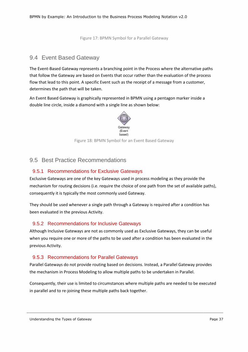
9.4 Event Based Gateway
The Event-Based Gateway represents a branching point in the Process where the alternative paths
that follow the Gateway are based on Events that occur rather than the evaluation of the process
flow that lead to this point. A specific Event such as the receipt of a message from a customer,
determines the path that will be taken.
An Event Based Gateway is graphically represented in BPMN using a pentagon marker inside a
double line circle, inside a diamond with a single line as shown below:
Figure 18: BPMN Symbol for an Event Based Gateway
9.5 Best Practice Recommendations
9.5.1 Recommendations for Exclusive Gateways
Exclusive Gateways are one of the key Gateways used in process modeling as they provide the
mechanism for routing decisions (i.e. require the choice of one path from the set of available paths),
consequently it is typically the most commonly used Gateway.
They should be used whenever a single path through a Gateway is required after a condition has
been evaluated in the previous Activity.
9.5.2 Recommendations for Inclusive Gateways
Although Inclusive Gateways are not as commonly used as Exclusive Gateways, they can be useful
when you require one or more of the paths to be used after a condition has been evaluated in the
previous Activity.
9.5.3 Recommendations for Parallel Gateways
Parallel Gateways do not provide routing based on decisions. Instead, a Parallel Gateway provides
the mechanism in Process Modeling to allow multiple paths to be undertaken in Parallel.
Consequently, their use is limited to circumstances where multiple paths are needed to be executed
in parallel and to re-joining these multiple paths back together.

BPMN by Example: An Introduction to the Business Process Modeling Notation v2.0
Understanding the Types of Gateway
Page 38
9.5.4 Recommendations for Event Based Gateways
Event Based Gateways provide the means of routing a Process based on waiting for the occurrence of
one of two or more events.
Although they are not commonly used, there are circumstances when Event Based Gateways are
useful.
An Event Based Gateway is to provide a means of handling waiting for the first occurrence of one of
two events. A typical use of an Event Based Gateway is to provide a time-out mechanism for the
handling of another event, for example, using a Timer Intermediate Event to provide a time-out
mechanism while waiting for the arrival of a Catching Message Event.
9.6 Case Study Implications
9.6.1 Using Exclusive Gateways in the Case Study
Exclusive Gateways are used in the Case Study in two of the three Process Diagrams, for example:
Three Exclusive Gateways (“Beverage Type”, “Coffee Type” and “Tea Type”) appear in the
“Capture Beverage Order” Process Diagram; and
Two Exclusive Gateways (“Beverage Type” and “Coffee Type”) appear in the “Prepare Beverage
Order” Process Diagram.
9.6.2 Using Inclusive Gateways in the Case Study
The “More Supplies” Inclusive Gateway is used in the “Retrieve More Supplies” Process Diagram to
handle the possibility that the Kitchen Hand may have been asked to retrieve additional Coffee
Supplies, Tea Supplies or both.
9.6.3 Using Parallel Gateways in the Case Study
There are no Parallel Gateways used in the Case Study.
9.6.4 Using Event Based Gateways in the Case Study
There are no Event Based Gateways used in the Case Study.

BPMN by Example: An Introduction to the Business Process Modeling Notation v2.0
Understanding the Types of Data
Page 39
10 Understanding the Types of Data
10.1 Overview of Data
As indicated in 2.3, Data objects in BPMN provide the mechanism to show how data or information is
created or consumed by a process.
The three different forms of Data Items are:
Data Object – represents an item of data that is either used or created by an Activity that only
exists for the current life of the Process;
Data Store – represents a collection of data that is either used or created by an Activity that exists
beyond the current life of the Process; and
Messages – represents the content of a communication that flows between two participants.
10.2 Data Objects
A Data Object is graphically represented in BPMN by a rectangle with a folded top right-hand corner,
as shown below:
Figure 19: BPMN Symbol for a Data Object
The standard (or normal) Data Object graphical symbol represents a single occurrence. A set or
collection of data is indicated by adding a visual attribute consisting of three vertical bars at the
bottom of the BPMN Symbol, as shown below:
Figure 20: BPMN Symbol for Data Object Collection
Data Objects can also have an additional visual attribute that shows if the Data Object is an Input or
Output to the Activity to which it is attached, which can also be combined with the Collection
attribute. Input and Output attribute is indicated by the use of an arrow in the top left of the Data
Object symbol, as shown below:
Figure 21: BPMN Symbol for Data Object with Input and Output attributes

BPMN by Example: An Introduction to the Business Process Modeling Notation v2.0
Understanding the Types of Data
Page 40
As shown above, the filled arrow is used to represent information flowing from an Activity to a Data
Object and the arrow without any filling represents information that flows from a Data Object to an
Activity.
10.3 Data Stores
A Data Store is graphically represented in BPMN by a cylinder with two additional arcs underneath
the type of the cylinder from one side to the other, as shown below:
Figure 22: BPMN Symbol for Data Store
Although it is not expressly defined, a Data Store usually represents a collection of information that
can be either held in a physical or electronic form, such as a file (e.g. paper-based file or an electronic
document) or a database (held electronically).
10.4 Messages
A Message is graphically represented in BPMN by an envelope, which is not filled in, as shown below:
Figure 23: BPMN Symbol for Message
10.5 Best Practice Recommendations
Data Objects, Data Stores or Message objects should be used to indicate key information used within
a Process.
The Data Objects will typically be used to indicate the inputs and outputs of Process or Activities.
For example:
Use a Data Object when:
o Key input documents are being used by an Activity, or
o Key output documents are being created by an Activity;
Use a Data Store when information is being used or created within a Process or across Processes;
and
Use a Message to document the information being passed in Message Flows.

BPMN by Example: An Introduction to the Business Process Modeling Notation v2.0
Understanding the Types of Data
Page 41
10.6 Case Study Implications
A Data Object is used on the Collaboration Diagram to indicate that the Barista passes a list of
additional supplies required to top-up their stock from the store room.
The Case Study also uses Message objects to show the information flowing to and from the Message
Events on the Collaboration Diagram.

BPMN by Example: An Introduction to the Business Process Modeling Notation v2.0
Understanding the types of Artefacts
Page 42
11 Understanding the types of Artefacts
11.1 Overview of Artefacts
As indicated in 2.3, Artefacts provide a set of elements that amplify other elements being
documented within the Process.
The two different types of Artefacts are:
Group Objects – allows flow objects to be grouped for purposes of documentation or analysis;
and
Annotation - provides additional information to elaborate an element within the process.
11.2 Group Objects
The Group object provides a visual mechanism to group elements on a Process diagram informally
and does not affect the flow of the process. The Group symbol can stretch across the boundaries of
Pools and is often used to highlight certain sections of a diagram without adding additional
constraints.
For example, a Group may be used to highlight further analysis.
A Group is graphically represented in BPMN using a rounded corner rectangle with a solid dashed
line as shown below:
Group
Figure 24: BPMN Symbol for Group Object
11.3 Annotations
The Annotation provides the ability to provide additional information for the reader of a BPMN
Diagram. The Annotation can be connected to a specific object in the process, but does not affect the
flow of the process.
An Annotation is graphically represented in BPMN using an open rectangle with a solid single line as
shown below:

BPMN by Example: An Introduction to the Business Process Modeling Notation v2.0
Understanding the types of Artefacts
Page 43
Annotation
Figure 25: BPMN Symbol for of Annotation Object
11.4 Best Practice Recommendations
Artefact objects provide a means for items to be highlighted or amplified in your Processes.
Consequently, care should be taken not to overuse them, as overuse runs the risk of either hiding the
overall process or hiding the items you actually want to highlight!
For example, consider only using:
Group Objects when there is something important and significant to show by grouping objects;
and
Annotations when you feel there is a need to explain something which is not immediately
apparent read the Process documentation, such as shown in the Case Study Collaboration
Diagram.
11.5 Case Study Implications
An Annotation object is used in the Collaboration Diagram for the Case Study to explain the role of
the Kitchen Hand in the Fulfil Beverage Order Process, as the Kitchen Hand would otherwise seem to
have no role within the Process.

BPMN by Example: An Introduction to the Business Process Modeling Notation v2.0
Understanding the types of Connecting Objects
Page 44
12 Understanding the types of Connecting Objects
12.1 Overview of Types of Connecting Objects
As outlined in 2.3, Connecting objects provide a set of connectors that are used to connect two
objects within a Process Model.
The three different types of Connecting Objects are:
Sequence Flows –shows the execution path (or order) of Process by connecting Flow Objects;
Message Flows – shows the flow of information in the form of Messages between Participants;
and
Associations – are used to attach Data objects or Artefact objects to Flow Objects, typically
Activities.
12.2 Sequence Flow Connecting Objects
There are three different Sequence Flow connections:
Normal Sequence Flow – is the normal and hence typical means of connecting two Flow Objects;
Default Sequence Flow – defines a default path following an Exclusive, Inclusive or Complex
Gateway; and
Conditional Sequence Flow – provides a pathway from an Activity that is only followed where a
defined condition is true.
Note: A Conditional Sequence Flow is only allowed when it comes from where there is more than
one Sequence Flow from an Activity.
Sequence Flow is graphically represented in BPMN by a single solid line with a solid arrow at one end,
as shown below:
Figure 26: BPMN Symbol for Sequence Flow
The two variations of Sequence Flow, Default and Conditional Sequence Flow, are graphically
represented in BPMN by a adding an element to the normal Sequence Flow BPMN Symbol. The
Default Sequence Flow is indicated by the use of a simple oblique line, like a back slash, on the end of
the line opposite to the arrow. The Conditional Sequence Flow is indicated by the use of a small
diamond, like a small Gateway Symbol, on the end of the line opposite to the arrow. These are
shown below:
Figure 27: BPMN Symbols for Default and Conditional Sequence Flows

BPMN by Example: An Introduction to the Business Process Modeling Notation v2.0
Understanding the types of Connecting Objects
Page 45
12.3 Message Flow Connecting Objects
As explained above (12.1), Message Flows are used to show the flow of Messages between two
Participants, who are prepared to send and receive them.
The key factor here is that as a Message Flow connects two Participants, the Message Flow must
connect two separate Pools and connect either to the Pool boundary or to a Flow Object within the
Pool boundary.
Note: A Message Flow must not connect two objects within the same Pool.
Message Flow is graphically represented in BPMN as a line with an open circle line start and an open
arrowhead line end with a dashed single line in between, as shown below:
Figure 28: BPMN Symbol for Message Flow
12.4 Association
As explained above (12.1), Associations are used to connect Artefact objects or Data objects to Flow
Objects, typically Activities.
Association is graphically represented in BPMN as a dashed single line between the connected
objects, as shown below:
Figure 29: BPMN Symbol for Association
The typical use of an Association is the connection of Data Objects to Activities. The Data Association
can also be used to indicate direction, by adding an arrow to the BPMN Symbol, as shown below:
Figure 30: BPMN Symbol for Directional Association
The direction of the association is used to indicate the direction with which the information flows
from the Data object to the Activity (or vice versa).
12.5 Best Practice Recommendations
12.5.1 Recommendations for Sequence Flow Connecting Objects
Most people are used to reading diagrams from left to right. Consequently, it is highly recommended
to draw your process models so that they can be easily read from left to right.
BPMN by Example: An Introduction to the Business Process Modeling Notation v2.0
Understanding the types of Connecting Objects
Page 46
An important factor in achieving this is to use the Sequence Flow object leaving from the right and
arriving on the left and not the top or bottom.
This not a technical requirement or a rule, rather it is a recommended style that will make your
process models more readable.
The next recommendation is to attempt to minimise the number of Sequence Flows that cross. The
best way of doing this is to use the Throw and Catch Link Intermediate Event.
12.5.2 Recommendations for Message Flow Connecting Objects
Message flow Objects typically flow vertically, connecting at one end to a Pool boundary (for Black
Box Pools) or an Activity and at the other end to either a Message Event or an Activity. Consequently,
it is recommended that Message Flow be drawn to flow from the top and bottom of the appropriate
object.
12.5.3 Recommendations for Associations
The only recommendation for Associations is to be careful in using the directional form of the
Association.
12.6 Case Study Implications
12.6.1 Implications for Sequence Flow Connecting Objects
The most commonly used BPMN symbol is the Sequence Flow, so it is no surprise that it is used in all
the process models in the Case Study!
12.6.2 Implications for Message Flow Connecting Objects
The Message Flow objects can only appear on Collaboration Diagrams and the Case Study
Collaboration Diagram includes six Message flow objects, which connect:
The Customer Pool to “Beverage Order Received” Message Event;
The “Capture Beverage Order” Sub-Process to and from the Customer Pool;
The “Beverage Order Captured” Message Event to the Customer Pool;
The “Beverage Order Prepared” Message Event to the Customer Pool; and
The “More Supplies Needed” Message Event to the Café Administration Pool
12.6.3 Implications for Associations
An Association object is used on the Collaboration Diagram to connect the “List of Required Supplies”
Data Object to the Collapsed Sub-Processes “Prepare Beverage Order” and “Retrieve More
Supplies”.
BPMN by Example: An Introduction to the Business Process Modeling Notation v2.0
Bringing it all together
Page 47
13 Bringing it all together
13.1 Overview
Understanding all the various Diagram types and Symbols in BPMN is only the start to understanding
how to document your processes. However, it is beyond the scope of this document to explore and
understand how to document your business processes. However in summary, to document your
business processes, you need to:
1. Define Scope of the Business Area
Define the area of business in which you are planning to document your business processes.
Understand what is within the scope and what is outside the scope.
2. Identify the Processes in Scope
With the scope of the business area, identify all the processes that are to be documented.
3. Prepare a High Level Process View
Prepare a Collaboration Diagram that documents the overall process in a summary view.
4. Analyze Contents of each Process
Investigate how each of the processes identified as being in scope are performed.
5. Document each Process
For each of the identified processes, prepare a Process Diagram to document the tasks within
each process.
13.2 Define Case Study Scope
The first step in documenting your processes is to define the scope of a business area.
The scope of the Case Study is limited to documenting the processes required for:
Taking beverage orders;
Preparing the beverage orders;
Restocking the beverage ingredients from the store room; and
Requesting that new beverage supplies be ordered when current stocks are low.
13.3 Identify Case Study Processes
The next step is to identify all the processes to be documented.
It is best practices to name the processes using a Verb Noun structure that explains the action (i.e.
the Verb) of the Process and the Object (i.e. the Noun) on which the Process is acting.

BPMN by Example: An Introduction to the Business Process Modeling Notation v2.0
Bringing it all together
Page 48
For the Case Study, the processes we have identified to document are:
Fulfil Beverage Order (the high level summary view);
Capture Beverage Order;
Prepare Beverages; and
Retrieve More Supplies.
13.4 Prepare high level Case Study Process View
The next step is to prepare a Collaboration Diagram providing a high level summary view of the
overall Process being documented.
The Collaboration diagram is the highest level diagram to be prepared and is used to provide a high
level summary view of the business area and shows how all the identified Processes interact with
each other.
For the Case Study, this looks like:
Figure 31: Collaboration Diagram - Fulfil Beverage Order

BPMN by Example: An Introduction to the Business Process Modeling Notation v2.0
Bringing it all together
Page 49
13.5 Analyze the Contents of each of the Case Study Processes
13.5.1 Overview
The next step is to analyze each of the identified processes to identify the component Activities or
Tasks within each of the processes.
13.5.2 Analyze Contents of Capture Beverage Order
The tasks that comprise the Process “Capture Beverage Order” include:
Review details of the Beverage Order;
Record specific details of each Beverage being ordered;
Update total amount of the Beverage order;
Request Payment of the Order;
Receive Payment for the Order; and
Settle Beverage order providing a receipt and the change.
13.5.3 Analyze Contents of Prepare Beverages
The tasks that comprise the Process “Prepare Beverage Order” include:
Review details of the Beverage Order;
Prepare each of Beverages ordered, with a different set of tasks to prepare Tea and Coffee orders;
and
Deliver prepared Beverages to the Customer; and
Request additional Supplies.
13.5.4 Analyze Contents of Retrieve More Supplies
The tasks that comprise the Process “Retrieve More Supplies” include:
Check levels of current Supplies;
For each of the Fetch each type of Supplies to top up the Barista’s supplies; and
Request new Supplies to be ordered if they are running low.
13.6 Document each of the Case Study Processes
13.6.1 Overview
The last step is to prepare a Process Diagram for each of the identified Processes.
For the Case Study, we need to prepare Process Diagrams for:
Capture Beverage Order;
Prepare Beverages; and
Retrieve More Supplies.
BPMN by Example: An Introduction to the Business Process Modeling Notation v2.0
Bringing it all together
Page 50
13.7 Details of BPMN Core Elements
Table 6: BPMN Diagram Types
Core Element Description Element Types
Collaboration
Diagram
A Collaboration Diagram documents the interactions between
a process and either other processes or a Party.
A Party can be external to the orgranisation or a different area
within the organization and is either to be responsibile for the
process or to provide necessary information for the process.
Each Party is represented by a Pool.
Not Applicable
Process Diagram A Process Diagram documents processes that are internal to
an organization or a specific area within the organization.
Consequently, a Process Diagram represents the processes
contained with a Single Pool. However, it may contain one or
more Lanes that are contained in a Pool or the Pool inherited
from a Collaboration Diagram.
Not Applicable
Table 7: Swim Lane Objects
Core Element Description Additional
Element Types
Pool A Pool represents a Party involved in a process. The Pool often
represents either a Party external to the organization being
modeled. However, a Pool can also be used to represent
different areas within the organization.
For example, the Customer of a process is typically shown as a
Pool within a process and a set of Pools can be used to
represent the various departments within an organization.
Not Applicable
Lane A Lane represents a role or position within the entity defined
by the Pool in which it contains. For example, if a Branch of a
Bank is shown as a Pool, then possible Lanes would be a Teller
or a person answering Customer Service Enquiries.
A Lane can be further subdivided into sub-Lanes. This notation
is used to represent different roles undertaken by the same
person or position.
Sub-Lane

BPMN by Example: An Introduction to the Business Process Modeling Notation v2.0
Bringing it all together
Page 51
Table 8: Flow Objects
Core Element Description Additional
Element Types
Event An event is something that has happened, may happen or
about to happen during a process. There are 4 different types
of Events, as shown to the right, with each type then divided
into sub-types.
For example, Start Events include None, Message, Time and
Conditional sub-types.
Start Event,
Intermediate
Event, End
Event, Boundary
Event
Activity An Activity is the work performed within a business process by
a participant and is either simple (i.e. the smallest item of
work, which is also known as atomic) or compound (i.e that
can be further decomposed into a set of simple and / or
compound item of work, which is also known as non-atomic).
A simple (or atomic) Activity is called a Task and a compound
(or non-atomic).
Activities can also have additional attributes or markers that
document additional properties, such as whether the Activity
is repeated or re-usable.
Task, Sub-
Process
Gateway A Gateway is used to control the sequence and flow within a
process, by providing routing, divergence or convergence
within a process. There are 6 different types of Gateways,
each of which has its own behaviour in how the path through
a process is undertaken.
Exclusive,
Inclusive,
Parallel,
Complex,
Event-based,
Parallel
Event-based
Table 9: Artefact Objects
Core Element Description Additional Types
Data Object A Data Object is used to provide details of the information
required by an Activity or produced by an Activity. A Data
Object can be used to represent a single item (called a Data
Object) or a set of items (called a Data Store).
Data Object,
Data Store
Group A Group is used to provide a visual means of allowing activities Not Applicable
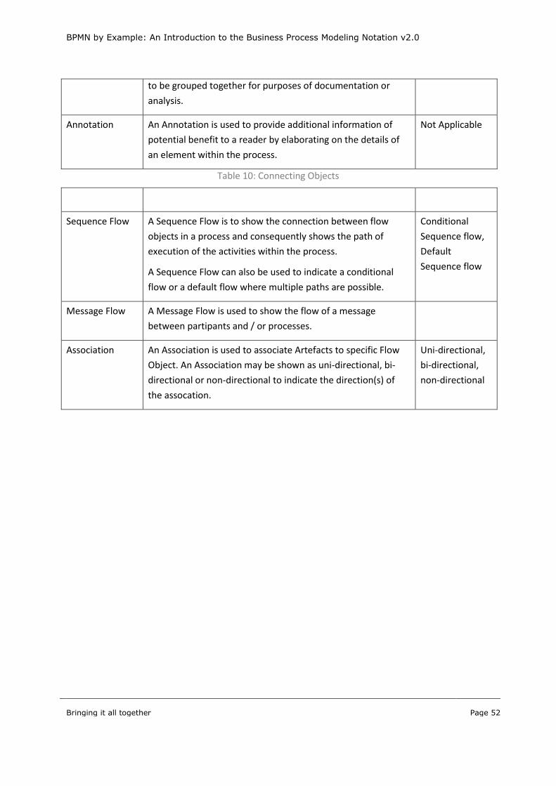
BPMN by Example: An Introduction to the Business Process Modeling Notation v2.0
Bringing it all together
Page 52
to be grouped together for purposes of documentation or
analysis.
Annotation An Annotation is used to provide additional information of
potential benefit to a reader by elaborating on the details of
an element within the process.
Not Applicable
Table 10: Connecting Objects
Core Element Description Additional Types
Sequence Flow A Sequence Flow is to show the connection between flow
objects in a process and consequently shows the path of
execution of the activities within the process.
A Sequence Flow can also be used to indicate a conditional
flow or a default flow where multiple paths are possible.
Conditional
Sequence flow,
Default
Sequence flow
Message Flow A Message Flow is used to show the flow of a message
between partipants and / or processes.
Association An Association is used to associate Artefacts to specific Flow
Object. An Association may be shown as uni-directional, bi-
directional or non-directional to indicate the direction(s) of
the assocation.
Uni-directional,
bi-directional,
non-directional
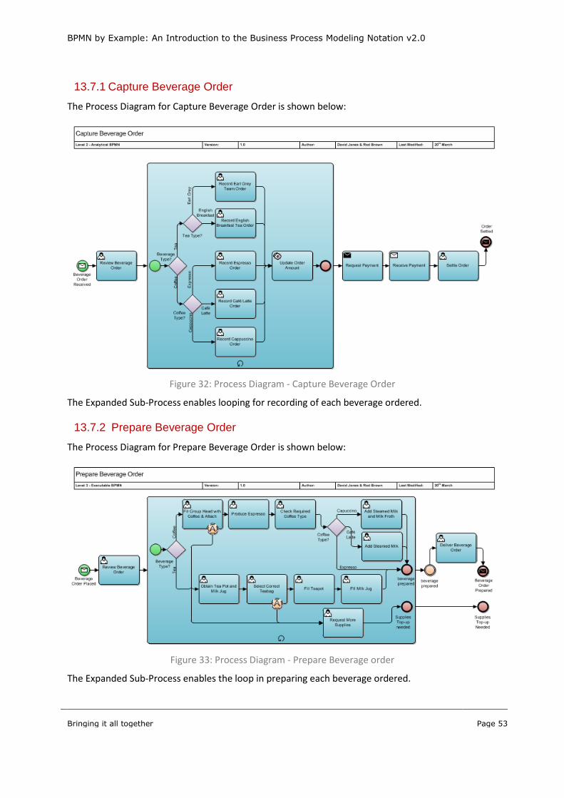
BPMN by Example: An Introduction to the Business Process Modeling Notation v2.0
Bringing it all together
Page 53
13.7.1 Capture Beverage Order
The Process Diagram for Capture Beverage Order is shown below:
Figure 32: Process Diagram - Capture Beverage Order
The Expanded Sub-Process enables looping for recording of each beverage ordered.
13.7.2 Prepare Beverage Order
The Process Diagram for Prepare Beverage Order is shown below:
Figure 33: Process Diagram - Prepare Beverage order
The Expanded Sub-Process enables the loop in preparing each beverage ordered.
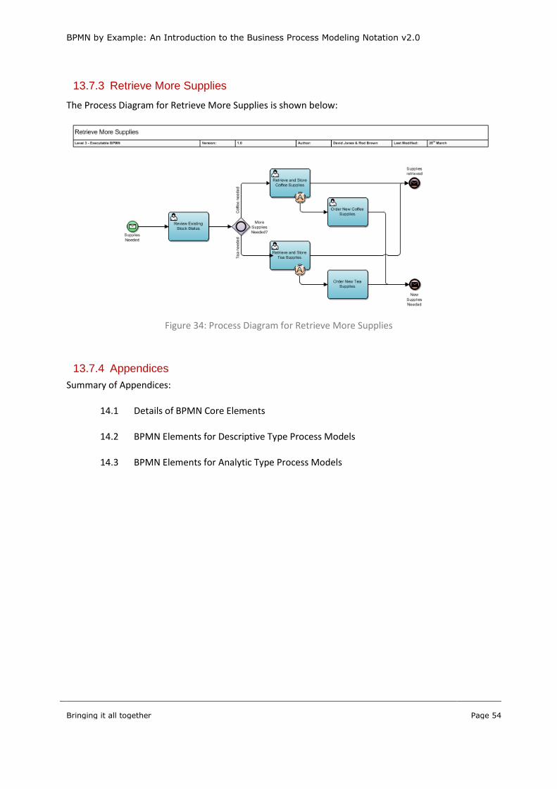
BPMN by Example: An Introduction to the Business Process Modeling Notation v2.0
Bringing it all together
Page 54
13.7.3 Retrieve More Supplies
The Process Diagram for Retrieve More Supplies is shown below:
Figure 34: Process Diagram for Retrieve More Supplies
13.7.4 Appendices
Summary of Appendices:
14.1 Details of BPMN Core Elements
14.2 BPMN Elements for Descriptive Type Process Models
14.3 BPMN Elements for Analytic Type Process Models
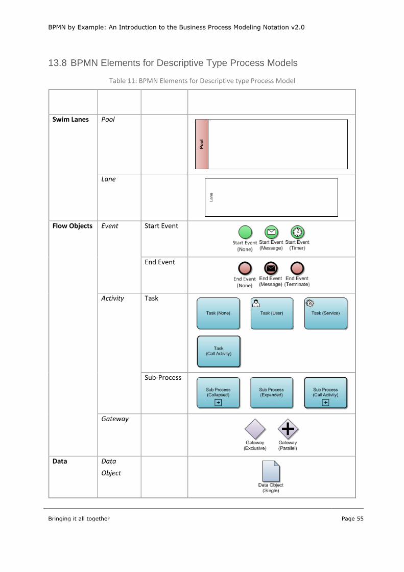
BPMN by Example: An Introduction to the Business Process Modeling Notation v2.0
Bringing it all together
Page 55
13.8 BPMN Elements for Descriptive Type Process Models
Table 11: BPMN Elements for Descriptive type Process Model
Category Element
Types
Element
Sub-types
Symbols for Descriptive Process Models
Swim Lanes Pool
Lane
Flow Objects Event Start Event
End Event
Activity Task
Sub-Process
Gateway
Data Data
Object
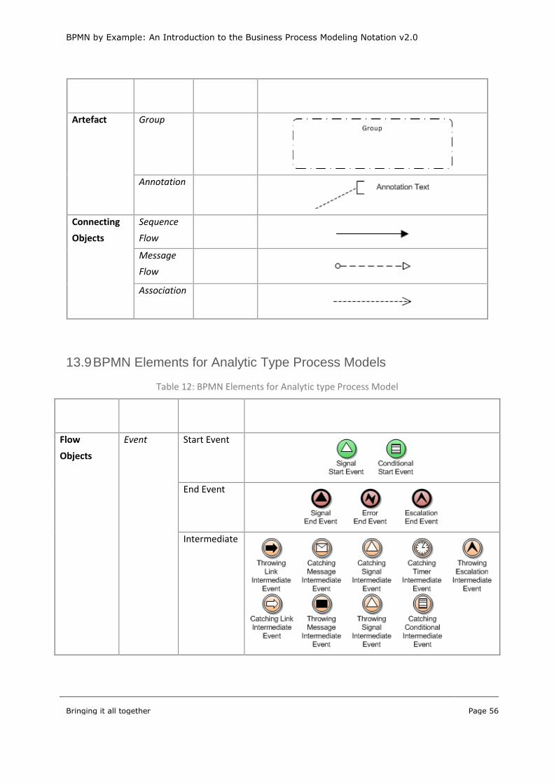
BPMN by Example: An Introduction to the Business Process Modeling Notation v2.0
Bringing it all together
Page 56
Category Element
Types
Element
Sub-types
Symbols for Descriptive Process Models
Artefact Group
Annotation
Connecting
Objects
Sequence
Flow
Message
Flow
Association
13.9 BPMN Elements for Analytic Type Process Models
Table 12: BPMN Elements for Analytic type Process Model
Category Element
Types
Element Sub-
types
Symbols for Descriptive Process Models
Flow
Objects
Event Start Event
End Event
Intermediate

BPMN by Example: An Introduction to the Business Process Modeling Notation v2.0
Bringing it all together
Page 57
Category Element
Types
Element Sub-
types
Symbols for Descriptive Process Models
Boundary
Intermediate
Activity Task
Sub-Process
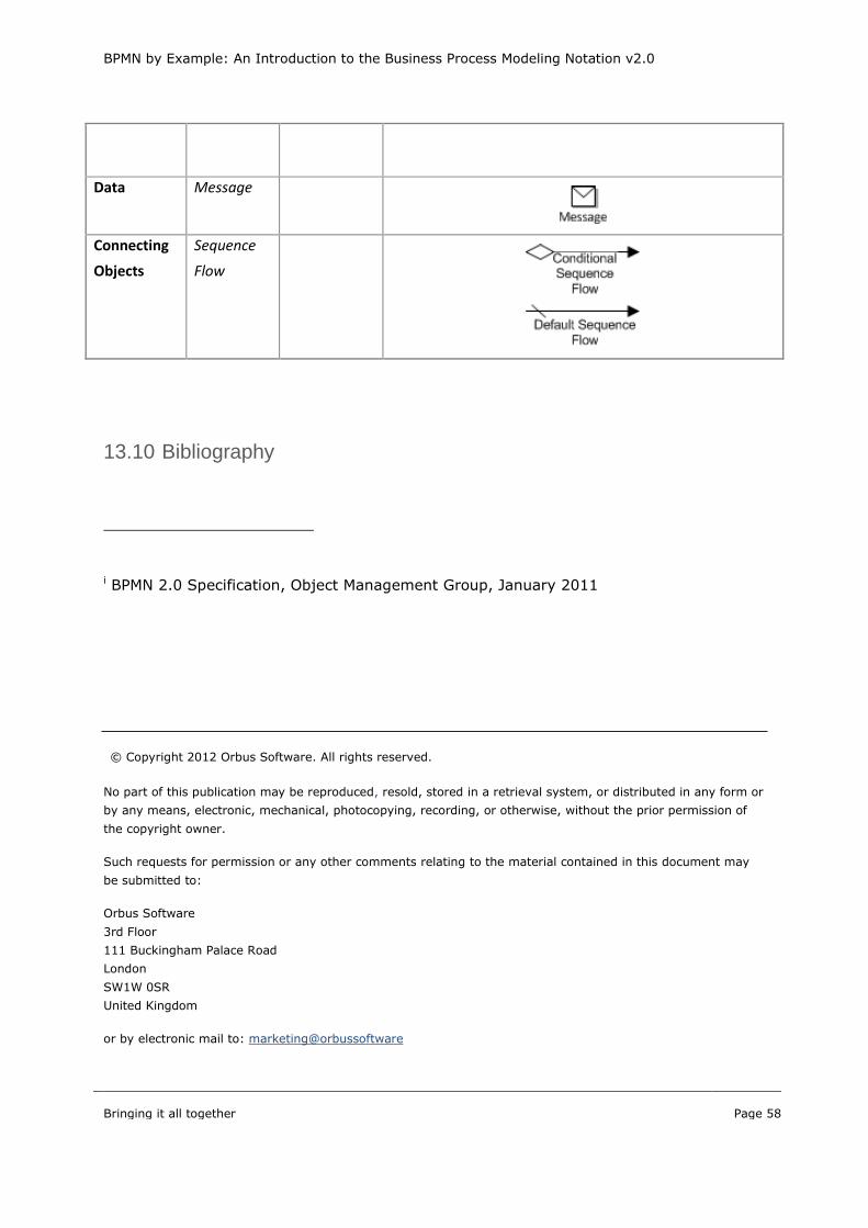
BPMN by Example: An Introduction to the Business Process Modeling Notation v2.0
Bringing it all together
Page 58
Category Element
Types
Element Sub-
types
Symbols for Descriptive Process Models
Data Message
Connecting
Objects
Sequence
Flow
13.10 Bibliography
i BPMN 2.0 Specification, Object Management Group, January 2011
© Copyright 2012 Orbus Software. All rights reserved.
No part of this publication may be reproduced, resold, stored in a retrieval system, or distributed in any form or
by any means, electronic, mechanical, photocopying, recording, or otherwise, without the prior permission of
the copyright owner.
Such requests for permission or any other comments relating to the material contained in this document may
be submitted to:
Orbus Software
3rd Floor
111 Buckingham Palace Road
London
SW1W 0SR
United Kingdom
or by electronic mail to: marketing@orbussoftware