BP GoM Fiber Optic Network: A Case Study is to present a case study of BP GoM and provide the...
6
Copyright © 2010 SubOptic Page 1 of 6 conference & convention enabling the next generation of networks & services BP GoM Fiber Optic Network: A Case Study Robert S. C. Munier 1 , Derek Buffitt and Robert Thomas Tyco Electronics Subsea Communications LLC 412 Mt Kemble Avenue, Morristown, NJ, 07960 USA Abstract: BP GoM is a technologically advanced trunk and branch undersea fiber optic system that provides connectivity between major offshore production platforms in the Gulf of Mexico and landing stations in Mississippi and Texas, part of a private network owned and operated by BP. The system has been in operation for two years and is the most significant investment in undersea fiber for offshore oil and gas application to date. The purpose of this paper is to present a case study of BP GoM and provide the historical setting, design requirements, unique features, construction methodology and operational experience of the network. 1. INTRODUCTION Gulf of Mexico oil and gas producers began considering fiber solutions for offshore platforms in the mid 1990’s. With the development of oil fields in deeper water and the installation of larger platforms, new telecommunications requirements were identified. The demand for bandwidth was growing but geographic diffusivity argued against the high cost of fiber to an individual or multiple platforms, especially when a producer’s platforms might be tens or hundreds of kilometers apart. Independent telecom operators attempted to develop solutions and enlist producers that would commit to buying a service on long-term contracts in order to finance an open access system. As a result of market and industry constraints, these solutions were never realized. Hurricanes Dennis, Katrina and Rita in the summer of 2005 caused operators to revisit fiber. Platforms in the storms’ paths had communications failures, or worse. Many platforms not directly in the hurricanes’ paths, including some deepwater, high value platforms, had significantly delayed returns to normal operations because their communications links were dependent upon near shore platforms that were impacted. Every day of downtime costs millions in lost production. 1. Current affiliation: Woods Hole Oceanographic Institution BP Americas, one of the major Gulf of Mexico producers with some of the most significant deepwater platforms on line and on the drawing board, saw an opportunity to improve operational efficiencies through the implementation of more reliable communications with minimal platform interdependences. BP also had significant initiatives for using digital information to manage offshore operations collaboratively with teams ashore. The confluence of these events provided the impetus for BP to decide to construct BP GoM, an advanced undersea fiber optic network designed to provide connectivity from offshore platforms to the BP operations center in Houston in a self-healing ring architecture. BP wanted a robust system that could serve existing deep water platforms, but also include the flexibility to be expanded and extended to accommodate future platforms. 2. DESIGN REQUIREMENTS The goal of BP GoM was to meet growing bandwidth needs for production data transfer, videoconferencing, remote management and security, and to facilitate emerging requirements for reservoir monitoring and automation. Because the Gulf of Mexico is a hurricane-prone region and BP’s deepwater investments there are among the world’s largest, a key objective was disaster-proofing. To these ends, BP
Transcript of BP GoM Fiber Optic Network: A Case Study is to present a case study of BP GoM and provide the...
Copyright © 2010 SubOptic Page 1 of 6
conference & convention enabling the next generation of networks & services
BP GoM Fiber Optic Network: A Case Study
Robert S. C. Munier1, Derek Buffitt and Robert Thomas Tyco Electronics Subsea Communications LLC
412 Mt Kemble Avenue, Morristown, NJ, 07960 USA Abstract: BP GoM is a technologically advanced trunk and branch undersea fiber optic system that provides connectivity between major offshore production platforms in the Gulf of Mexico and landing stations in Mississippi and Texas, part of a private network owned and operated by BP. The system has been in operation for two years and is the most significant investment in undersea fiber for offshore oil and gas application to date. The purpose of this paper is to present a case study of BP GoM and provide the historical setting, design requirements, unique features, construction methodology and operational experience of the network. 1. INTRODUCTION Gulf of Mexico oil and gas producers began considering fiber solutions for offshore platforms in the mid 1990’s. With the development of oil fields in deeper water and the installation of larger platforms, new telecommunications requirements were identified. The demand for bandwidth was growing but geographic diffusivity argued against the high cost of fiber to an individual or multiple platforms, especially when a producer’s platforms might be tens or hundreds of kilometers apart. Independent telecom operators attempted to develop solutions and enlist producers that would commit to buying a service on long-term contracts in order to finance an open access system. As a result of market and industry constraints, these solutions were never realized. Hurricanes Dennis, Katrina and Rita in the summer of 2005 caused operators to revisit fiber. Platforms in the storms’ paths had communications failures, or worse. Many platforms not directly in the hurricanes’ paths, including some deepwater, high value platforms, had significantly delayed returns to normal operations because their communications links were dependent upon near shore platforms that were impacted. Every day of downtime costs millions in lost production. 1. Current affiliation: Woods Hole Oceanographic Institution
BP Americas, one of the major Gulf of Mexico producers with some of the most significant deepwater platforms on line and on the drawing board, saw an opportunity to improve operational efficiencies through the implementation of more reliable communications with minimal platform interdependences. BP also had significant initiatives for using digital information to manage offshore operations collaboratively with teams ashore. The confluence of these events provided the impetus for BP to decide to construct BP GoM, an advanced undersea fiber optic network designed to provide connectivity from offshore platforms to the BP operations center in Houston in a self-healing ring architecture. BP wanted a robust system that could serve existing deep water platforms, but also include the flexibility to be expanded and extended to accommodate future platforms. 2. DESIGN REQUIREMENTS
The goal of BP GoM was to meet growing bandwidth needs for production data transfer, videoconferencing, remote management and security, and to facilitate emerging requirements for reservoir monitoring and automation. Because the Gulf of Mexico is a hurricane-prone region and BP’s deepwater investments there are among the world’s largest, a key objective was disaster-proofing. To these ends, BP
Copyright © 2010 SubOptic Page 2 of 6
conference & convention enabling the next generation of networks & services
had the following basic system design criteria:
• Provide connectivity between designated deepwater offshore platforms and two diverse landing points over 1000 km apart.
• Initially serve 19 primary platforms, with the capability of expansion to 32 platforms on each of two fiber pairs
• Provide a discrete 10 Gb/s wavelength from each primary platform (east and west-bound) to each landing.
• Avoid any primary platform interdependencies.
• Limit the number of seafloor-to-platform communication riser cables at each platform to one.
• Facilitate expansion to secondary platforms using seafloor connections.
• Limit use of telecom floor space on each platform to two standard bays.
Trade studies were performed comparing a repeaterless festoon with a powered system. While it was determined that a repeaterless solution would be more economical to construct, BP’s design criteria called for a long haul, highly expandable solution, emphasizing robustness over low cost. The result was the system depicted in Figures 1 & 2. 3. SYSTEM DESIGN The system features an 1100 km, 2 fiber pair, powered trunk with landings in Mississippi and Texas and 19 repeaterless branches to existing or planned high value platforms. One fiber pair is reserved for connection to BP platforms and the second fiber pair is available for connections to third party facilities. The geographically diverse landings protect against a single hurricane event removing the whole system from service. Branch lengths can be up to 100 km long each, and the trunk can be expanded by
300 km to allow for future growth farther offshore. The system is a hybrid of undersea technologies, incorporating a traditional long haul, optically-amplified design on the trunk with repeaterless branches. Broadband optical add/drop multiplexing (OADM) branching units (BU) on the trunk provide bandwidth to each branch so that every primary platform has its own discrete path to both cable stations ashore, eliminating any interdependencies. This is accomplished using optical filters and 10 Gb/s optical transceivers on each platform, mated with transceivers in each cable station, operating at an assigned wavelength. The optical transceivers have a small form factor and low power requirements so the infrastructure requirements on each platform are modest. GigE interfaces on the platforms provide direct connection to on-board routers and local area networks. The system design includes two trunk fiber pairs with OADM BUs serving one or the other fiber pair, providing the means to segregate traffic between BP and third party users. 4. UNIQUE FEATURES The BP GoM system design incorporated numerous unique features in order to meet initial design and expansion requirements. Many of these features are depicted in Figures 1 & 3. The mechanical connections to the platforms incorporated both mature, as well as new, features and solutions. BP platforms are in water depths between 1200 and 2000 m and several required the installation of dynamic fiber optic risers, a cable technology deployed successfully for a first generation fiber optic system in Brazil. The individual platform interfaces required detailed engineering and their marine installation involved extensive

Copyright © 2010 SubOptic Page 3 of 6
conference & convention enabling the next generation of networks & services
Figure 1: BP GoM FON Project Layout
Figure 2: Fiber Pair Connectivity
Copyright © 2010 SubOptic Page 4 of 6
conference & convention enabling the next generation of networks & services
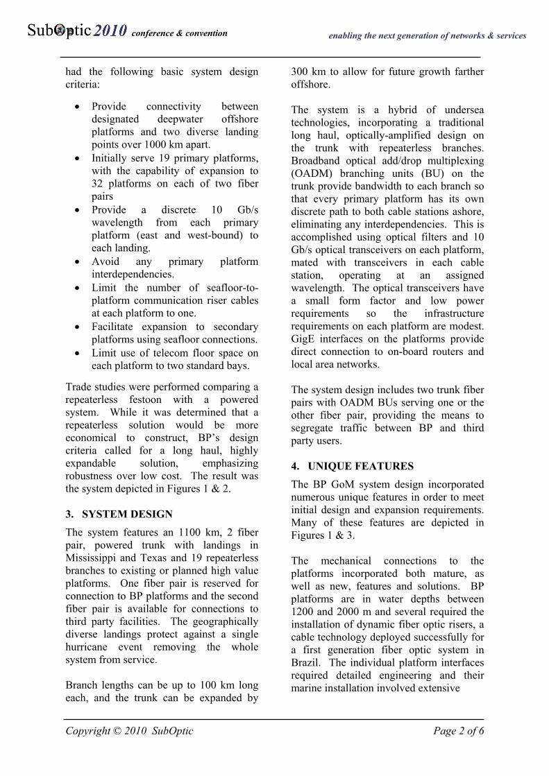
planning and coordination. Critical to the riser catenary configuration was the incorporation of newly revised hurricane design criteria based on the 2005 hurricane experience.
Figure 3: Unique Features
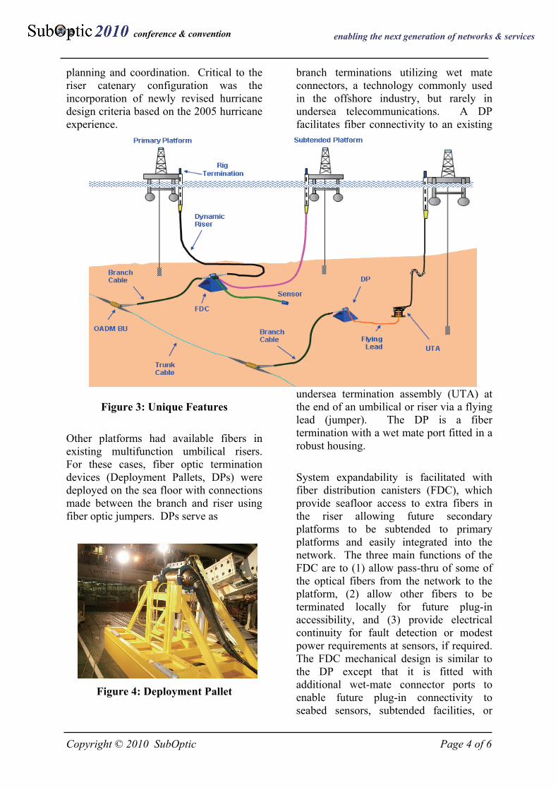
Other platforms had available fibers in existing multifunction umbilical risers. For these cases, fiber optic termination devices (Deployment Pallets, DPs) were deployed on the sea floor with connections made between the branch and riser using fiber optic jumpers. DPs serve as
Figure 4: Deployment Pallet
branch terminations utilizing wet mate connectors, a technology commonly used in the offshore industry, but rarely in undersea telecommunications. A DP facilitates fiber connectivity to an existing
undersea termination assembly (UTA) at the end of an umbilical or riser via a flying lead (jumper). The DP is a fiber termination with a wet mate port fitted in a robust housing.
System expandability is facilitated with fiber distribution canisters (FDC), which provide seafloor access to extra fibers in the riser allowing future secondary platforms to be subtended to primary platforms and easily integrated into the network. The three main functions of the FDC are to (1) allow pass-thru of some of the optical fibers from the network to the platform, (2) allow other fibers to be terminated locally for future plug-in accessibility, and (3) provide electrical continuity for fault detection or modest power requirements at sensors, if required. The FDC mechanical design is similar to the DP except that it is fitted with additional wet-mate connector ports to enable future plug-in connectivity to seabed sensors, subtended facilities, or
Copyright © 2010 SubOptic Page 5 of 6
conference & convention enabling the next generation of networks & services
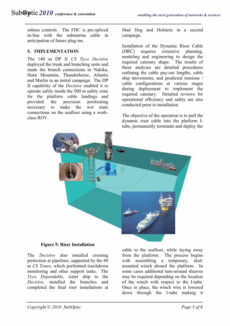
subsea controls. The FDC is pre-spliced in-line with the submarine cable in anticipation of future plug-ins. 5. IMPLEMENTATION The 140 m DP II CS Tyco Decisive deployed the trunk and branching units and made the branch connections to Nakika, Horn Mountain, Thunderhorse, Atlantis and Marlin in an initial campaign. The DP II capability of the Decisive enabled it to operate safely inside the 500 m safety zone for the platform cable landings and provided the precision positioning necessary to make the wet mate connections on the seafloor using a work-class ROV.
Figure 5: Riser Installation The Decisive also installed crossing protection at pipelines, supported by the 80 m CS Teneo, which performed touchdown monitoring and other support tasks. The Tyco Dependable, sister ship to the Decisive, installed the branches and completed the final riser installations at
Mad Dog and Holstein in a second campaign. Installation of the Dynamic Riser Cable (DRC) requires extensive planning, modeling and engineering to design the required catenary shape. The results of these analyses are detailed procedures outlining the cable pay-out lengths, cable ship movements, and predicted tensions / cable configurations at various stages during deployment to implement the required catenary. Detailed reviews for operational efficiency and safety are also conducted prior to installation. The objective of the operation is to pull the dynamic riser cable into the platform I-tube, permanently terminate and deploy the
cable to the seafloor, while laying away from the platform. The process begins with assembling a temporary, skid-mounted winch aboard the platform. In some cases additional turn-around sheaves may be required depending on the location of the winch with respect to the I-tube. Once in place, the winch wire is lowered down through the I-tube making it
Copyright © 2010 SubOptic Page 6 of 6
conference & convention enabling the next generation of networks & services
accessible underwater, at the platform keel, for attachment by an ROV to a messenger line from the cable ship. The winch wire is pulled onto the ship, and the riser pull-in head secured to the winch wire and readied for over-boarding. As the winch wire pulls in, the cable ship pays out the DRC through the water column. During the pay-out, elements may be attached to the riser cable below the pull-in head as needed, such as centralizers used to maintain positioning of the riser cable within the I-tube. Critical elements in the installation process are attaching the pull-in head to the I-tube and securing the bend limiting device at the entry of the I-tube. Once secure, the cable ship lays away, deploying the DRC. If required, buoyancy and ballast modules are secured to the riser to produce the desired “lazy wave” catenary configuration. In the vicinity of riser touch down on the sea bed, the prescribed abrasion protection is secured and deployed.
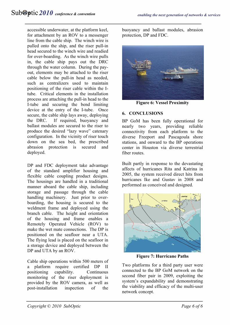
DP and FDC deployment take advantage of the standard amplifier housing and flexible cable coupling product designs. The housings are handled in a traditional manner aboard the cable ship, including storage and passage through the cable handling machinery. Just prior to over-boarding, the housing is secured to the weldment frame and deployed using the branch cable. The height and orientation of the housing and frame enables a Remotely Operated Vehicle (ROV) to make the wet mate connections. The DP is positioned on the seafloor near a UTA. The flying lead is placed on the seafloor in a storage device and deployed between the DP and UTA by an ROV. Cable ship operations within 500 meters of a platform require certified DP II positioning capability. Continuous monitoring of the riser deployment is provided by the ROV camera, as well as post-installation inspection of the
buoyancy and ballast modules, abrasion protection, DP and FDC.
Figure 6: Vessel Proximity 6. CONCLUSIONS BP GoM has been fully operational for nearly two years, providing reliable connectivity from each platform to the diverse Freeport and Pascagoula shore stations, and onward to the BP operations center in Houston via diverse terrestrial fiber routes. Built partly in response to the devastating affects of hurricanes Rita and Katrina in 2005, the system received direct hits from hurricanes Ike and Gustav in 2008 and performed as conceived and designed.
Figure 7: Hurricane Paths Two platforms for a third party user were connected to the BP GoM network on the second fiber pair in 2009, exploiting the system’s expandability and demonstrating the viability and efficacy of the multi-user network concept.