BOX CAMS & BUMP CAMS - daytonlamina.com · BOX CAMS AND BUMP CAMS ServiCe We Deliver AND QUAlity...
32
BOX CAMS & BUMP CAMS
-
Upload
truongkhanh -
Category
Documents
-
view
228 -
download
0
Transcript of BOX CAMS & BUMP CAMS - daytonlamina.com · BOX CAMS AND BUMP CAMS ServiCe We Deliver AND QUAlity...
BOX CAMS & BUMP CAMS

BOX CAMS AND BUMP CAMS
ServiCe We Deliver AND QUAlity yOU CAN DePeND ONieM is a leading manufacturer of die and mold components supplied globally to the parts forming industry. Backed by years of tool and die experience, quality and innovation are some of the reasons why our name is respected throughout the world. We have taken the lead role in creating and bringing new products to customers and helping them find solutions that improve their operations. Based on the capabilities ieM offers, we can help you to meet the demands of quick deliveries, technical support, quality products and competitive prices. ieM and its’ broad distribution channels and direct sales personnel will assist you in any way to make your product a better and more profitable one.
Whether standard or customized products, with our years of experience, customers can be sure the products they receive will meet their expectations for reliability and dependable performance. We understand the demanding schedules of die builders and production personnel and have developed efficient manufacturing processes to shorten product lead times as well as put inventory on our shelves so you can have it in your facility when you need it.
Included in our full line offering are both inch and metric size die components that are designed to die standards including ISO, NAAMS, JIS and many automotive and appliance manufacturers' standards. The complete product offering includes:
Accu-BendTM Rotary BendersCams Aerial & Diemount Cams Box & Bump Cams Roller Cams Wide CamsDie AccessoriesGuide Posts & Bushings Plain & Ball Bearing Styles Steel, Bronze, Bronze-Plated & Self-Lubricating Bushings Lempcoloy Bushings Special Pins, Bushings & RetainersHydraulics Electronic Die Setters Die Separators Drill & Tap Equipment Hydraulic Motors
In-Die Tapping UnitsMold Components Bronze Plated & Self-Lubricated Bushings Leader Pins Bronze & Bronze Plated Wear Strips & WaysPunches, Buttons & RetainersSprings DieMax L Inch Series Springs DieMax XL Series ISO Springs JIS Series Springs Custom Heavy Duty Springs Marsh Mellow Springs Formathane Urethane Kaller Gas Springs Utility & Disc SpringsWear Products Plates, Strips, Gibs & Blocks Steel, bronze, Bronze-Plated and Self-Lubricating Materials

i
Contents
Cam Selection Matrix ii
Retainer Mounting Methods iv
Mini CamTM 1
Standard Box Cam 6
Bump Cam 11
Maximum Power Heavy Duty CamTM (MP) 14
Long Travel Box Cam 17
Custom Cams 23
page number
ii
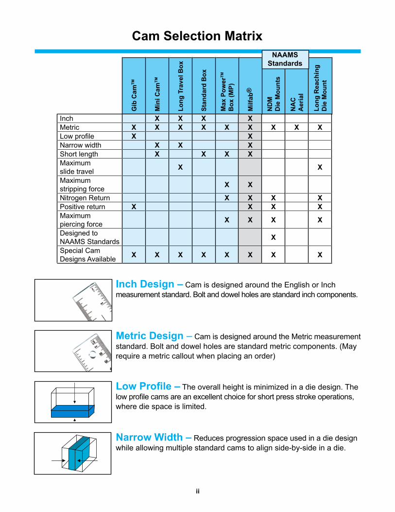
Cam Selection Matrix
inch Design – Cam is designed around the English or Inch measurement standard. Bolt and dowel holes are standard inch components.
Metric Design – Cam is designed around the Metric measurement standard. Bolt and dowel holes are standard metric components. (May require a metric callout when placing an order)
Low Profile – The overall height is minimized in a die design. The low profile cams are an excellent choice for short press stroke operations, where die space is limited.
Narrow Width – Reduces progression space used in a die design while allowing multiple standard cams to align side-by-side in a die.
Gib
Cam
tM
Min
i Cam
tM
long
tra
vel B
ox
Stan
dard
Box
Max
Pow
ertM
Box
(MP)
Milf
ab®
ND
M
Die
Mou
nts
NA
C
Aer
ial
long
rea
chin
gD
ie M
ount
Inch X X X XMetric X X X X X X X X XLow profile X XNarrow width X X XShort length X X X XMaximumslide travel X X
Maximumstripping force X X
Nitrogen Return X X X XPositive return X X X XMaximumpiercing force X X X X
Designed toNAAMS Standards X
Special CamDesigns Available X X X X X X X X
NAAMSStandards

iii
Cam Selection Matrix
Short length – The short length design is ideal for working at the edge of a die or on the inside of a large part working out. The length of the cam is minimized by an internal spring return.
Maximum Slide travel/long reaching – The slide travel increases by 30% or more over standard design cams. Cams are good in applications where there is a need to reach over large part flanges or stock material placement limits the proximity of the cam.
Maximum Stripping Force – Return spring force is 10% of working force. May require Nitrogen Return option.
Nitrogen return – Gas springs are designed into the cam to provide higher stripping forces and even slide return. Cams with nitrogen gas springs will either come standard with a gas spring or may be an option to replace or use in combination with standard mechanical springs.
Positive return – A mechanical return designed into the cam to pull the slide and tooling out of the part. Ideal for applications piercing large holes or in sticky materials where there is a chance of die damage due to a stuck punch.
Maximum Piercing Force – Large self lubricated surface areas on moving parts provides maximum piercing forces over long extended periods of cam operation.
Designed to NAAMS Standards – Cams meet or exceed all of the NAAMS Global Standards for Aerial and Die Mount Cam design.
Special Cam Designs – If a standard cam design doesn’t work for you, then give us your application specifications and we will design a special cam for you. S

iv
retainer Mounting Methods
StANDArD retAiNer StANDArD retAiNer StANDArD retAiNer
The soft mounting face of the cam slide allows for the mounting of a standard light or heavy duty punch retainer.
Oversized retainers work well if multiple punches are set in
an even load pattern in relation to the center of the slide.
Off-center loads will reduce the working tonnage rating of the cam.
Multiple retainers easily fit our “double wide” #4L and #14L cams. Applications requiring off-center loading of the slide reduces the working tonnage
rating of the cam.
GANG MOUNtiNG retAiNerS ON (2) CAMS
Using a bridge block fastened on the slide face of two of the same cams allows for mounting of multiple retainers. Precise timing of both cam
slides ensures load sharing between the cams.
1
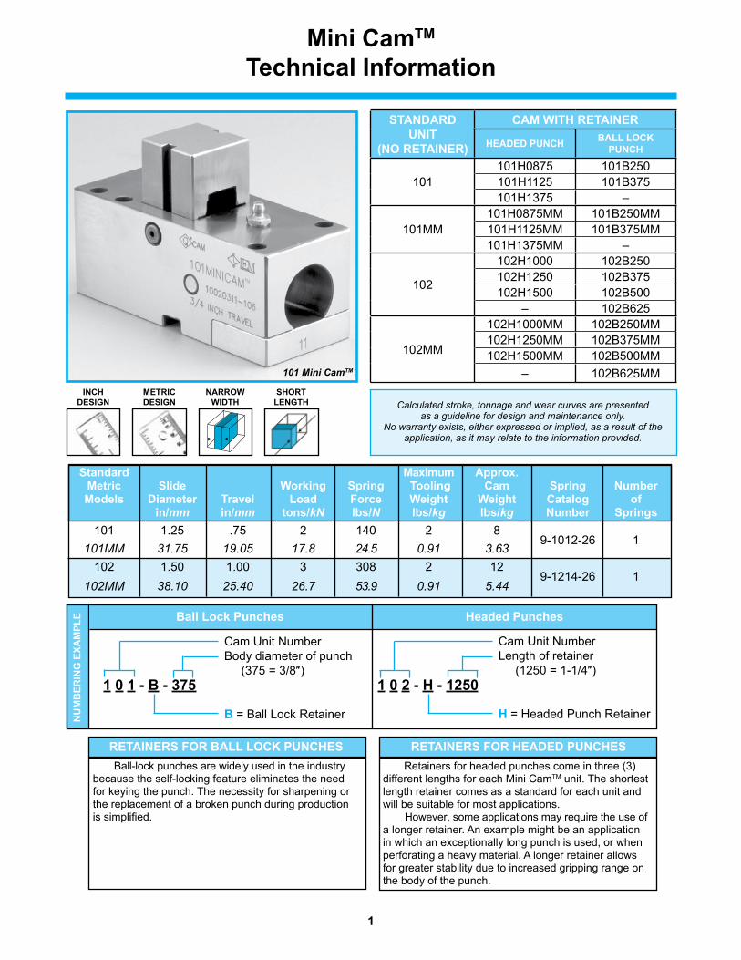
Mini CamtM technical information
101 Mini CamTM
NArrOW WiDtH
SHOrt leNGtH
iNCH DeSiGN
MetriC DeSiGN Calculated stroke, tonnage and wear curves are presented
as a guideline for design and maintenance only. No warranty exists, either expressed or implied, as a result of the
application, as it may relate to the information provided.
NU
MB
eriN
G e
XAM
Ple
Cam Unit NumberBody diameter of punch (375 = 3/8″)
B = Ball Lock Retainer
1 0 1 - B - 375
Ball lock Punches
Cam Unit NumberLength of retainer (1250 = 1-1/4″)
H = Headed Punch Retainer
1 0 2 - H - 1250
Headed Punches
Ball-lock punches are widely used in the industry because the self-locking feature eliminates the need for keying the punch. The necessity for sharpening or the replacement of a broken punch during production is simplified.
retAiNerS FOr BAll lOCK PUNCHeS Retainers for headed punches come in three (3) different lengths for each Mini CamTM unit. The shortest length retainer comes as a standard for each unit and will be suitable for most applications. However, some applications may require the use of a longer retainer. An example might be an application in which an exceptionally long punch is used, or when perforating a heavy material. A longer retainer allows for greater stability due to increased gripping range on the body of the punch.
retAiNerS FOr HeADeD PUNCHeS
Standard Maximum Approx. Metric Slide Working Spring tooling Cam Spring Number Models Diameter travel load Force Weight Weight Catalog of in/mm in/mm tons/kN lbs/N lbs/kg lbs/kg Number Springs 101 1.25 .75 2 140 2 8
9-1012-26 1
101MM 31.75 19.05 17.8 24.5 0.91 3.63 102 1.50 1.00 3 308 2 12
9-1214-26 1 102MM 38.10 25.40 26.7 53.9 0.91 5.44
StANDArD UNit
(NO retAiNer)
CAM WitH retAiNer
HeADeD PUNCH BAll lOCK PUNCH
101101H0875 101B250101H1125 101B375101H1375 –
101MM101H0875MM 101B250MM101H1125MM 101B375MM101H1375MM –
102
102H1000 102B250102H1250 102B375102H1500 102B500
– 102B625
102MM
102H1000MM 102B250MM102H1250MM 102B375MM102H1500MM 102B500MM
– 102B625MM

2
5.50"/139.7mm5.00"/127.0mm
.50"/12.7mm
1.25"/31.8mm
1.625"/41.3mm3.125"/79.4mm .25"/6.4mm
2.0"
/50.
8mm
2.25
"/57
.2m
m
.50"/12.70mm
4X 5/16" [M8]SCREWS
2X 5/16" [M8]DOWELS
.75"/19.05mm
2.87
5"/7
3.0m
m
3.125"/79.375mmTRAVEL.75"/19.1mm
.26 x .500"/6.0 x 12.0mm(C) SLIDE EXTENDED
A
1.125"/28.575mm
1.125"/28.575mm
Ø1.25"/31.75mm
(B) DIAMETER
MAXIMUM PUNCH HEAD DIAMETER0.687"/17.44mm
D
Mini CamtM 101/101MM Slide Unit
Cam models are designed in both inch and metric.
Listed dimensions may not convert directly into the other standard.
All dimensions are for reference only and no tolerance is stated or implied.
Catalog retainer Height Number Dimension with D retainer in/mm 101H0875 .875 (22.2) 101H1125 1.125 (28.6) 101H1375 1.375 (34.9) 101B250 1.000 (25.4) 101B375 1.000 (25.4)
CatalogNumber
withretainer
Ain/mm
Bin/mm
Cin/mm
Headed Punches light DutyBall lockPunches
in
ShapedPoint
in
roundPoint
in
101H0875 3/89.5
.18844.79
5-7/8149.2 3/16 – 3/8 up to 3/8 —
101H1125 5/815.9
.18844.79
6-1/8155.6 3/16 – 3/8 up to 3/8 —
101H1375 7/822.2
.18844.79
6-3/8161.9 3/16 – 3/8 up to 3/8 —
101B250 11/1617.5
.25036.36
6-3/16157.2 — — 1/4
101B375 11/1617.5
.3759.53
6-3/16157.2 — — 3/8
3
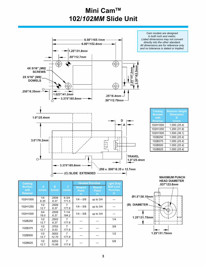
Mini CamtM 102/102MM Slide Unit
Cam models are designed in both inch and metric.
Listed dimensions may not convert directly into the other standard.
All dimensions are for reference only and no tolerance is stated or implied.
Catalog retainer Height Number Dimension with D retainer in/mm 102H1000 1.000 (25.4) 102H1250 1.250 (31.8) 102H1500 1.500 (38.1) 102B250 1.000 (25.4) 102B375 1.000 (25.4) 102B500 1.000 (25.4) 102B625 1.000 (25.4)
CatalogNumber
withretainer
Ain/mm
Bin/mm
Cin/mm
Headed Punches light DutyBall lockPunches
in
ShapedPoint
in
roundPoint
in
102H1000 1/46.35
.25096.37
6-3/4171.5 1/4 – 5/8 up to 3/4 —
102H1250 1/212.7
.25096.37
7177.8 1/4 – 5/8 up to 3/4 —
102H1500 3/419.0
.25096.37
7-1/4184.2 1/4 – 5/8 up to 3/4 —
102B250 1/212.7
.25036.37
7177.8 — — 1/4
102B375 1/212.7
.37539.53
7177.8 — — 3/8
102B500 1/212.7
.500312.70
7177.8 — — 1/2
102B625 1/212.7
.625315.88
7177.8 — — 5/8
4
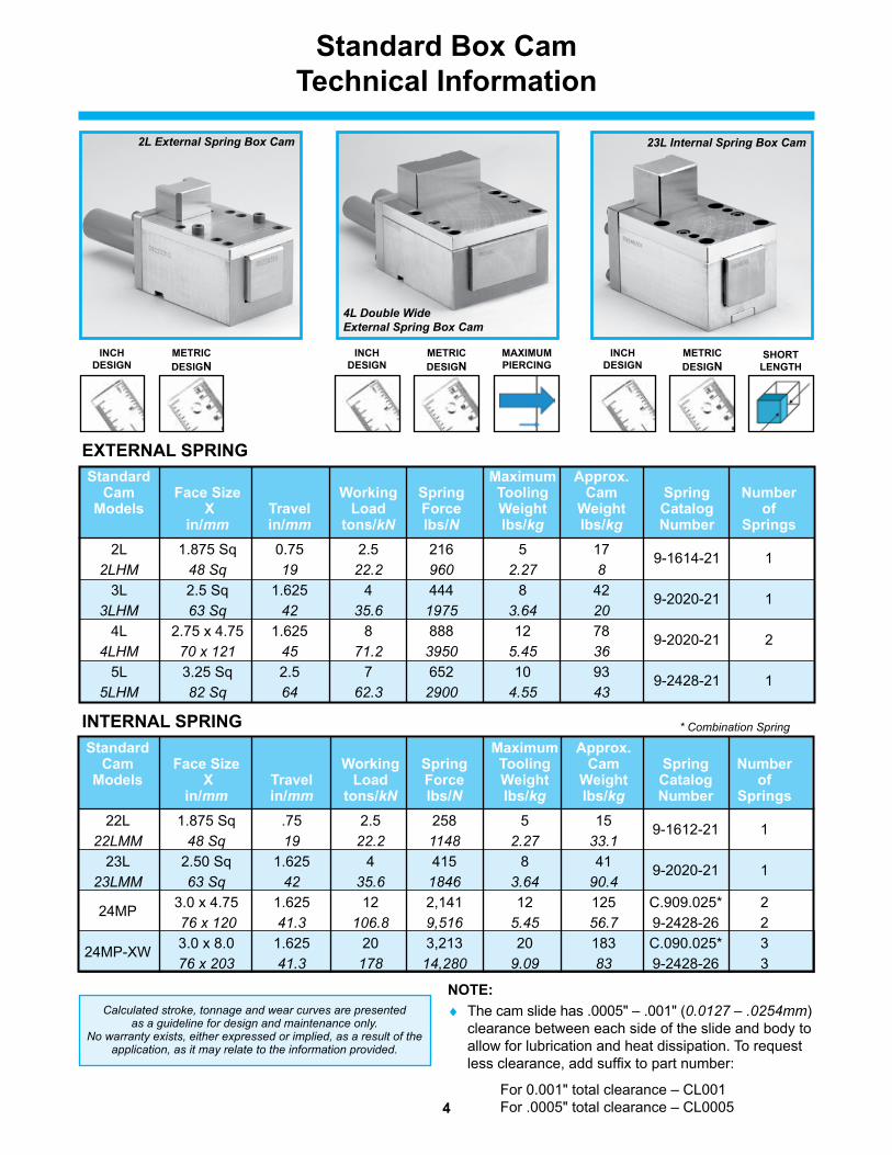
Standard Box Camtechnical information
2L External Spring Box Cam 23L Internal Spring Box Cam
4L Double Wide External Spring Box Cam
iNCH DeSiGN
MetriC DeSiGN
SHOrt leNGtH
iNCH DeSiGN
MetriC DeSiGN
eXterNAl SPriNG
iNCH DeSiGN
MetriC DeSiGN
MAXiMUM PierCiNG
NOte:♦ The cam slide has .0005" – .001" (0.0127 – .0254mm)
clearance between each side of the slide and body to allow for lubrication and heat dissipation. To request less clearance, add suffix to part number:
For 0.001" total clearance – CL001 For .0005" total clearance – CL0005
iNterNAl SPriNG
Calculated stroke, tonnage and wear curves are presented as a guideline for design and maintenance only.
No warranty exists, either expressed or implied, as a result of the application, as it may relate to the information provided.
* Combination Spring
Standard Maximum Approx. Cam Face Size Working Spring tooling Cam Spring Number Models X travel load Force Weight Weight Catalog of in/mm in/mm tons/kN lbs/N lbs/kg lbs/kg Number Springs 2L 1.875 Sq 0.75 2.5 216 5 17 9-1614-21 1 2LHM 48 Sq 19 22.2 960 2.27 8 3L 2.5 Sq 1.625 4 444 8 42 9-2020-21 1 3LHM 63 Sq 42 35.6 1975 3.64 20 4L 2.75 x 4.75 1.625 8 888 12 78 9-2020-21 2 4LHM 70 x 121 45 71.2 3950 5.45 36 5L 3.25 Sq 2.5 7 652 10 93 9-2428-21 1 5LHM 82 Sq 64 62.3 2900 4.55 43
Standard Maximum Approx. Cam Face Size Working Spring tooling Cam Spring Number Models X travel load Force Weight Weight Catalog of in/mm in/mm tons/kN lbs/N lbs/kg lbs/kg Number Springs 22L 1.875 Sq .75 2.5 258 5 15 9-1612-21 1 22LMM 48 Sq 19 22.2 1148 2.27 33.1 23L 2.50 Sq 1.625 4 415 8 41 9-2020-21 1 23LMM 63 Sq 42 35.6 1846 3.64 90.4 24MP 3.0 x 4.75 1.625 12 2,141 12 125 C.909.025* 2 76 x 120 41.3 106.8 9,516 5.45 56.7 9-2428-26 2 24MP-XW 3.0 x 8.0 1.625 20 3,213 20 183 C.090.025* 3 76 x 203 41.3 178 14,280 9.09 83 9-2428-26 3
5
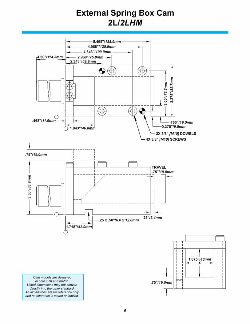
external Spring Box Cam2l/2LHM
Cam models are designed in both inch and metric.
Listed dimensions may not convert directly into the other standard.
All dimensions are for reference only and no tolerance is stated or implied.

6
external Spring Box Cam3l/3LHM
Cam models are designed in both inch and metric.
Listed dimensions may not convert directly into the other standard.
All dimensions are for reference only and no tolerance is stated or implied.
7
7.625"/194.1mm
6.50"/165.1mm
8.25"/209.5mm
3.625"/98.1mm 4.50"/122.1mm
6.75"/170.1mm
.875"/22.1mm
3.00"/76.2mm.563"/14.0mm
6.43
7"/1
64.0
mm
7.00
"/17
7.8m
m
1.125"/28.6mm
1.00"/25.4mm
4.75"/121mmX
4X 1/2" [M12] SCREWS2X 1/2" [M12] DOWELS
3.000"/85.1mm
TRAVEL1.625"/45.0mm
0.25"/8.0mm
1.625"/50mm
5.12
5"/1
35.0
mm
.313 x .625"/12.0 x 25.0mm
2.750"/70mm
4L - 45°4LHM - 48°
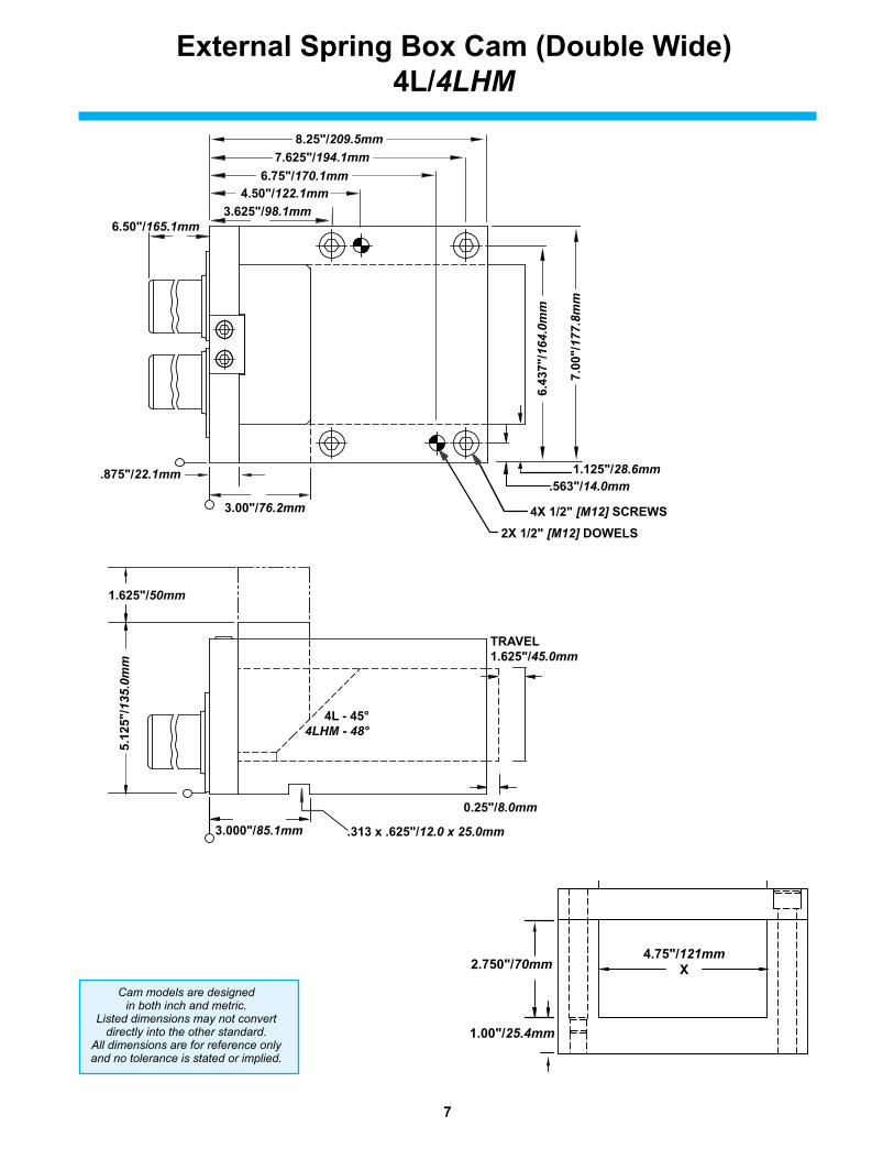
external Spring Box Cam (Double Wide)4l/4LHM
7.625"/194.1mm
6.50"/165.1mm
8.25"/209.5mm
3.625"/98.1mm 4.50"/122.1mm
6.75"/170.1mm
.875"/22.1mm
3.00"/76.2mm.563"/14.0mm
6.43
7"/1
64.0
mm
7.00
"/17
7.8m
m
1.125"/28.6mm
1.00"/25.4mm
4.75"/121mmX
4X 1/2" [M12] SCREWS2X 1/2" [M12] DOWELS
3.000"/85.1mm
TRAVEL1.625"/45.0mm
0.25"/8.0mm
1.625"/50mm
5.12
5"/1
35.0
mm
.313 x .625"/12.0 x 25.0mm
2.750"/70mm
4L - 45°4LHM - 48°
Cam models are designed in both inch and metric.
Listed dimensions may not convert directly into the other standard.
All dimensions are for reference only and no tolerance is stated or implied.
8
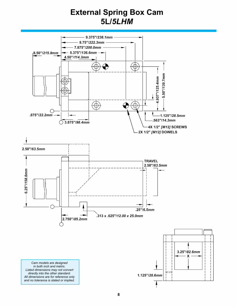
external Spring Box Cam5l/5LHM
Cam models are designed in both inch and metric.
Listed dimensions may not convert directly into the other standard.
All dimensions are for reference only and no tolerance is stated or implied.
9
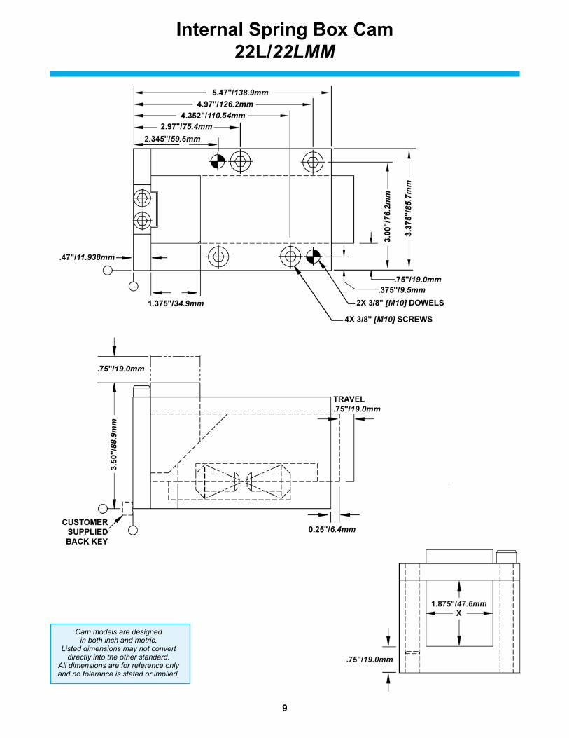
internal Spring Box Cam22l/22LMM
Cam models are designed in both inch and metric.
Listed dimensions may not convert directly into the other standard.
All dimensions are for reference only and no tolerance is stated or implied.

10
internal Spring Box Cam23l/23LMM
Cam models are designed in both inch and metric.
Listed dimensions may not convert directly into the other standard.
All dimensions are for reference only and no tolerance is stated or implied.
11
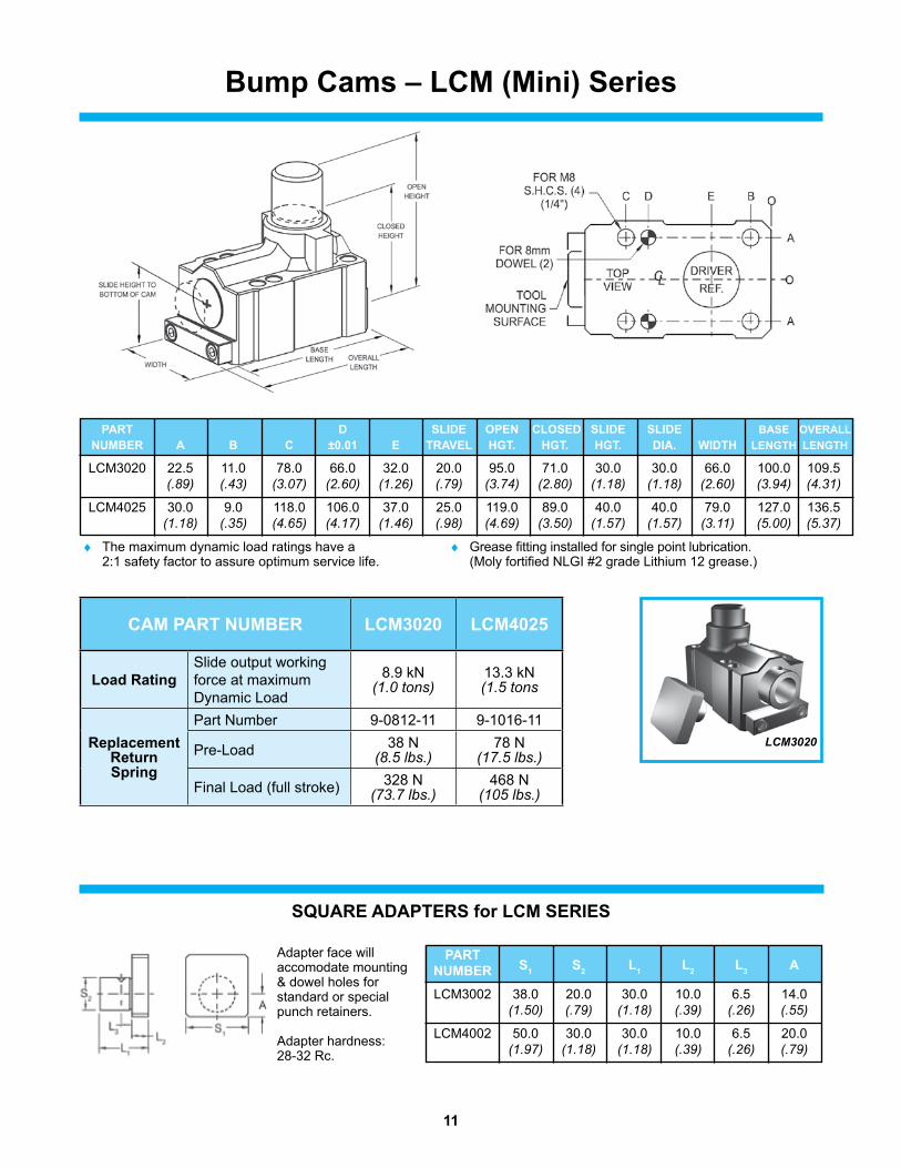
Bump Cams – lCM (Mini) Series
Adapter face will accomodate mounting & dowel holes for standard or special punch retainers.
Adapter hardness:28-32 Rc.
LCM3020
SQUAre ADAPterS for lCM SerieS
PArt D SliDe OPeN ClOSeD SliDe SliDe BASe OverAll NUMBer A B C ±0.01 e trAvel HGt. HGt. HGt. DiA. WiDtH leNGtH leNGtH
LCM3020 22.5 11.0 78.0 66.0 32.0 20.0 95.0 71.0 30.0 30.0 66.0 100.0 109.5 (.89) (.43) (3.07) (2.60) (1.26) (.79) (3.74) (2.80) (1.18) (1.18) (2.60) (3.94) (4.31)
LCM4025 30.0 9.0 118.0 106.0 37.0 25.0 119.0 89.0 40.0 40.0 79.0 127.0 136.5 (1.18) (.35) (4.65) (4.17) (1.46) (.98) (4.69) (3.50) (1.57) (1.57) (3.11) (5.00) (5.37)
♦ The maximum dynamic load ratings have a 2:1 safety factor to assure optimum service life.
♦ Grease fitting installed for single point lubrication. (Moly fortified NLGI #2 grade Lithium 12 grease.)
PArt NUMBer S1 S2 l1 l2 l3 A
LCM3002 38.0 20.0 30.0 10.0 6.5 14.0 (1.50) (.79) (1.18) (.39) (.26) (.55)
LCM4002 50.0 30.0 30.0 10.0 6.5 20.0 (1.97) (1.18) (1.18) (.39) (.26) (.79)
CAM PArt NUMBer lCM3020 lCM4025
load ratingSlide output working force at maximum Dynamic Load
8.9 kN(1.0 tons)
13.3 kN(1.5 tons
replacementreturn Spring
Part Number 9-0812-11 9-1016-11
Pre-Load 38 N(8.5 lbs.)
78 N(17.5 lbs.)
Final Load (full stroke) 328 N(73.7 lbs.)
468 N(105 lbs.)
12
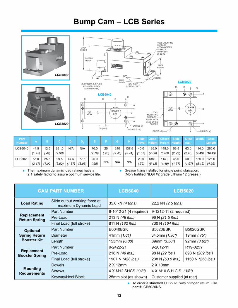
Bump Cam – lCB Series
Part A B C D1 D2 e F G H
Slide Open Closed Slide Slide Width Base Number travel Height Height Height (sq.) length
LCB6040 44.5 12.5 251.5 N/A N/A 70.0 25 240 137.5 40.0 195.0 148.0 56.5 63.0 114.0 265.0 (1.75) (.49) (9.90) (2.76) (.98) (9.45) (5.41) (1.57) (7.68) (5.83) (2.22) (2.48) (4.49) (10.43)
LCB5020 55.0 25.5 99.5 47.5 77.5 25.0 N/A N/A N/A
20.0 138.0 114.0 45.0 50.0 130.0 125.0 (2.17) (1.00) (3.92) (1.87) (3.05) (.98) (.79) (5.43) (4.49) (1.77) (1.97) (5.12) (4.92)
♦ The maximum dynamic load ratings have a 2:1 safety factor to assure optimum service life.
♦ Grease fitting installed for single point lubrication. (Moly fortified NLGI #2 grade Lithium 12 grease.)
lCB5020
lCB6040
LCB6040
LCB5020
CAM PArt NUMBer lCB6040 lCB5020
load rating Slide output working force at maximum Dynamic Load 35.6 kN (4 tons) 22.2 kN (2.5 tons)
replacementreturn Spring
Part Number 9-1012-21 (4 required) 9-1212-11 (2 required)Pre-Load 213 N (48 lbs.) 96 N (21.5 lbs.)Final Load (full stroke) 811 N (182 lbs.) 730 N (164 lbs.)
OptionalSpring return
Booster Kit
Part Number B6040BSK B5020BSK B5020GSKDiameter 41mm (1.61) 34.5mm (1.36") 19mm (.75")Length 153mm (6.00) 89mm (3.50") 92mm (3.62")
replacmentBooster Spring
Part Number 9-2422-21 9-2012-11 R19-025YPre-Load 218 N (49 lbs.) 98 N (22 lbs.) 898 N (202 lbs.)Final Load (full stroke) 1907 N (428 lbs.) 238 N (53.5 lbs.) 1150 N (258 lbs.)
Mountingrequirements
Dowels 2 X 12mm 2 X 10mmScrews 4 X M12 SHCS (1/2") 4 X M10 S.H.C.S. (3/8")Keyway/Heel Block 25mm slot (as shown) Customer supplied (at rear)
♦ To order a standard LCB5020 with nitrogen return, use part #LCB5020NS.

13
OPtiON 2Part #LCB5020DNS Similar to LCB5020D, except with Nitrogen Gas Springs.Complete with (2) 1/2" Dowel Holes, (4) 3/8" S.H.C.S. and Special Slide.
To retrofit a standard LCB5020, order kit #B5020GSK.
to order a standard lCB5020 with nitrogen return, use part #LCB5020NS
Standard Bump Cam (Metric)Part #LCB5020(2) 10mm Dowel Holes with (4) 10mm S.H.C.S.
Standard Bump Cam (imperial)Part #LCB5020I(2) 1/2" Dowel Holes with (4) 3/8 S.H.C.S.
OPtiON 1Customized Bump Cam (imperial)Part #LCB5020DComplete with (2) 1/2" Dowel Holes, (4) 3/8 S.H.C.S., Special Slide and additional booster kit.
To retrofit a standard LCB5020, order kit #B5020BSK.
Bump Cam Options
14
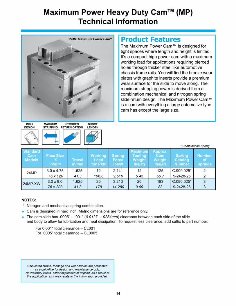
iNCH DeSiGN
24MP Maximum Power CamTM
MAXiMUM StriPPiNG
SHOrt leNGtH
NitrOGeN retUrN OPtiON
Maximum Power Heavy Duty CamtM (MP)technical information
The Maximum Power Cam™ is designed for tight spaces where length and height is limited. It’s a compact high power cam with a maximum working load for applications requiring pierced holes through thicker steel like automotive chassis frame rails. You will find the bronze wear plates with graphite inserts provide a premium wear surface for the slide to move along. The maximum stripping power is derived from a combination mechanical and nitrogen spring slide return design. The Maximum Power Cam™ is a cam with everything a large automotive type cam has except the large size.
Product Features
NOteS: 1 Nitrogen and mechanical spring combination.♦ Cam is designed in hard inch. Metric dimensions are for reference only.♦ The cam slide has .0005" – .001" (0.0127 – .0254mm) clearance between each side of the slide
and body to allow for lubrication and heat dissipation. To request less clearance, add suffix to part number:
For 0.001" total clearance – CL001 For .0005" total clearance – CL0005
Calculated stroke, tonnage and wear curves are presented as a guideline for design and maintenance only.
No warranty exists, either expressed or implied, as a result of the application, as it may relate to the information provided.
* Combination Spring
Standard Maximum Approx. Cam Face Size Working Spring tooling Cam Spring Number Models X travel load Force Weight Weight Catalog of in/mm in/mm tons/kN lbs/N lbs/kg lbs/kg Number Springs 24MP 3.0 x 4.75 1.625 12 2,141 12 125 C.909.025* 2 76 x 120 41.3 106.8 9,516 5.45 56.7 9-2428-26 2 24MP-XW 3.0 x 8.0 1.625 20 3,213 20 183 C.090.025* 3 76 x 203 41.3 178 14,280 9.09 83 9-2428-26 3

15
Maximum Power Heavy Duty CamtM (MP)24MP
All dimensions are for reference only and no tolerance is stated or implied.

16
Maximum Power Heavy Duty CamtM (MP)24MP-XW
All dimensions are for reference only and no tolerance is stated or implied.
TRAVEL1.625"/41.3mm
6.88
"/174
.6m
m
1.625"/41.3mm
3.000"/76.2mm
1.03"/26.0mm
7.030"/178.4mm5.023"/127.4mm
11.0
0"/2
79.4
mm
4.030"/102.2mm
10.4
4"/2
65.1
mm
1.50"/38.1mm.56"/14.3mm
8.4"/213.4mm9.28"/235.6mm
LIFTING HOLE
3.13"/79.4mm
8.00"/203.2mm3.00"/76.2mm
4X 1/2" [M12] SCREWS2X 1/2" [M12] DOWELS
.25"/6.4mm
3.53"/89.66mm .55" x 1.00/14.00 x 25.4mm
7.00
0"/1
78m
m
8.50
0"/2
16m
m
17
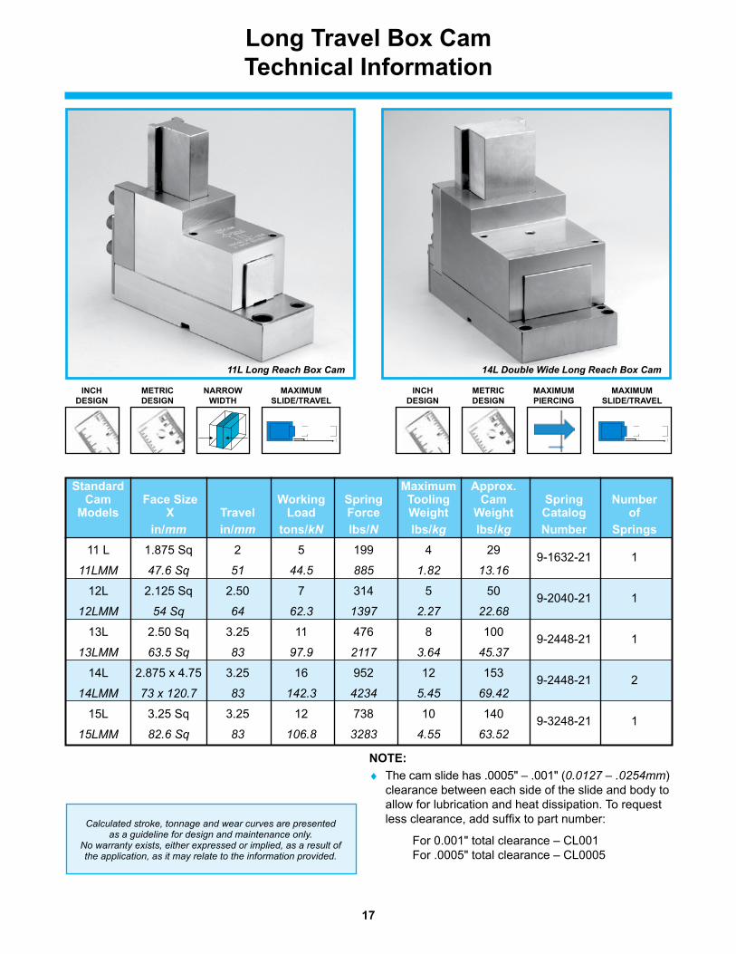
long travel Box Camtechnical information
11L Long Reach Box Cam 14L Double Wide Long Reach Box Cam
NArrOW WiDtH
MAXiMUM SliDe/trAvel
MetriC DeSiGN
MAXiMUM PierCiNG
MAXiMUM SliDe/trAvel
iNCH DeSiGN
MetriC DeSiGN
iNCH DeSiGN
Calculated stroke, tonnage and wear curves are presented as a guideline for design and maintenance only.
No warranty exists, either expressed or implied, as a result of the application, as it may relate to the information provided.
NOte:♦ The cam slide has .0005" – .001" (0.0127 – .0254mm)
clearance between each side of the slide and body to allow for lubrication and heat dissipation. To request less clearance, add suffix to part number:
For 0.001" total clearance – CL001 For .0005" total clearance – CL0005
Standard Maximum Approx. Cam Face Size Working Spring tooling Cam Spring Number Models X travel load Force Weight Weight Catalog of in/mm in/mm tons/kN lbs/N lbs/kg lbs/kg Number Springs 11 L 1.875 Sq 2 5 199 4 29 9-1632-21 1 11LMM 47.6 Sq 51 44.5 885 1.82 13.16
12L 2.125 Sq 2.50 7 314 5 50 9-2040-21 1 12LMM 54 Sq 64 62.3 1397 2.27 22.68
13L 2.50 Sq 3.25 11 476 8 100 9-2448-21 1
13LMM 63.5 Sq 83 97.9 2117 3.64 45.37
14L 2.875 x 4.75 3.25 16 952 12 153 9-2448-21 2
14LMM 73 x 120.7 83 142.3 4234 5.45 69.42
15L 3.25 Sq 3.25 12 738 10 140 9-3248-21 1 15LMM 82.6 Sq 83 106.8 3283 4.55 63.52
18
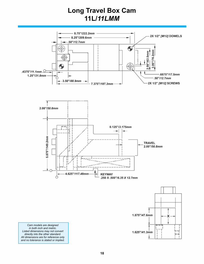
long travel Box Cam11l/11LMM
Cam models are designed in both inch and metric.
Listed dimensions may not convert directly into the other standard.
All dimensions are for reference only and no tolerance is stated or implied.

19
2.50"/63.5mm
7.00
"/17
7.8m
m
5.125"/130.2mm
TRAVEL2.50"/63.5mm
X2.125"/54.0mm
1.875"/47.6mm
10.50"/266.7mm 11.00"/279.4mm
.50"/12.7mm
.56"/14.2mm
3.00
"/76
.2m
m
3.50
"/88
.9m
m
3.94"/100.1mm9.50"/241.3mm
1.50"/38.1mm .50"/12.7mm.685"/17.4mm
2X 1/2" [M12] DOWELS
2X 1/2" [M12] SCREWS
0.125"/3.175mm
KEYWAY5/16 X 5/8"/7.94 X 15.88mm
long travel Box Cam12l/12LMM
Cam models are designed in both inch and metric.
Listed dimensions may not convert directly into the other standard.
All dimensions are for reference only and no tolerance is stated or implied.
20
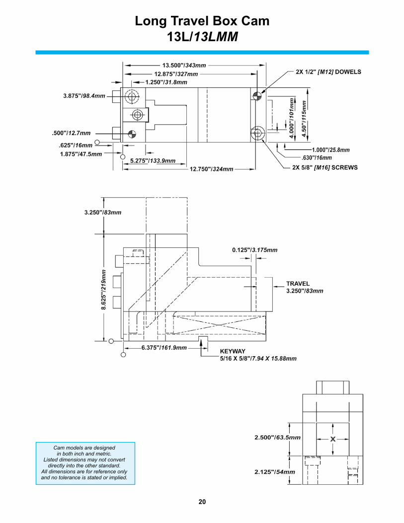
long travel Box Cam13l/13LMM
Cam models are designed in both inch and metric.
Listed dimensions may not convert directly into the other standard.
All dimensions are for reference only and no tolerance is stated or implied.

21
long travel Box Cam (Double Wide)14l/14LMM
Cam models are designed in both inch and metric.
Listed dimensions may not convert directly into the other standard.
All dimensions are for reference only and no tolerance is stated or implied.

22
long travel Box Cam15l/15LMM
Cam models are designed in both inch and metric.
Listed dimensions may not convert directly into the other standard.
All dimensions are for reference only and no tolerance is stated or implied.

23
Custom Cams
Although ieM has a large offering of catalog cams, we realize that in today’s competitive environment, a catalog cam doesn’t always fit all applications.
Custom cams include:♦ Cams engineered by ieM specifically for your application♦ Cams machined to your design
CUStOM CAM CAPABilitieS:
♦ CAM DeSiGN ieM’s engineering team designs for any application
♦ CAM MANUFACtUriNG ieM can build your cam design Machining – components up to 900mm Flame hardening with minimal distortion
BeNeFitS:
♦ Frees up your design resources♦ Frees up your machine capacity♦ Provides the best solution for your application♦ Can improve your project scheduling♦ Saves you money as compared to in-house costs♦ Lets you focus on your core competencies
Cam design screen print
Product Features
24
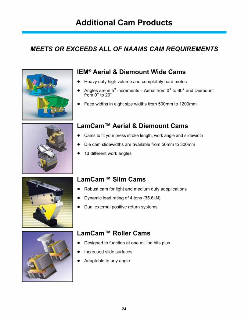
Additional Cam Products
MEETS OR EXCEEDS ALL OF NAAMS CAM REQUIREMENTS
lamCam™ Aerial & Diemount Cams●Cams to fit your press stroke length, work angle and slidewidth
●Die cam slidewidths are available from 50mm to 300mm
●13 different work angles
lamCam™ roller Cams●Designed to function at one million hits plus
●Increased slide surfaces
●Adaptable to any angle
lamCam™ Slim Cams●Robust cam for light and medium duty aqpplications
●Dynamic load rating of 4 tons (35.6kN)
●Dual external positive return systems
ieM® Aerial & Diemount Wide Cams●Heavy duty high volume and completely hard metric
●Angles are in 5° increments – Aerial from 0° to 60° and Diemount from 0° to 20°
●Face widths in eight size widths from 500mm to 1200mm
CL
165 (125 SERIES)
190 (150 SERIES)
160
136 ± 0.013
130
35
X2 ± 0.013
X1 ± 0.025
305
X3X6
X7
25 TYP
Z1
X8 REF
300 ± 0.5
102.5 ± 0.025
X5
140
(DOWELS
± 0.013) 165
20
55 ± 0.013
135
130(50° & 60°
ONLY)
28(0° - 4
5°
& 55°)
75
150
Ø16 SHCS (4)
Ø16 (H7) DOWEL (2)
Note: T.B. (N
AAMS M011222)
SHOWN IN NAAMS DEFINED LOCATION,
B
A
ANGLE
TOOLING BALL OFFSET FROM CTR.
( - DIM = T.B
. BELOW CTR.)
50° & 60° ONLY
IS FOR REFERENCE ONLY, PART AND
MOUNTING PROVISIONS NOT INCL
12
Ø16 SHCS (4)
Ø16 (H7) DOWEL (2)
BASE (BODY)
LCDRIVER
SLID
ELC
13
X4 ('A' to 'B')
(+ DIM. = RIGHT)
Z2
125 & 150 SERIES AERIAL CAMS
20 ±0.25Ø10 (H7)
80 ±0.25
100 ±0.25
Ø6 (H7) (2)
Cam Products
21
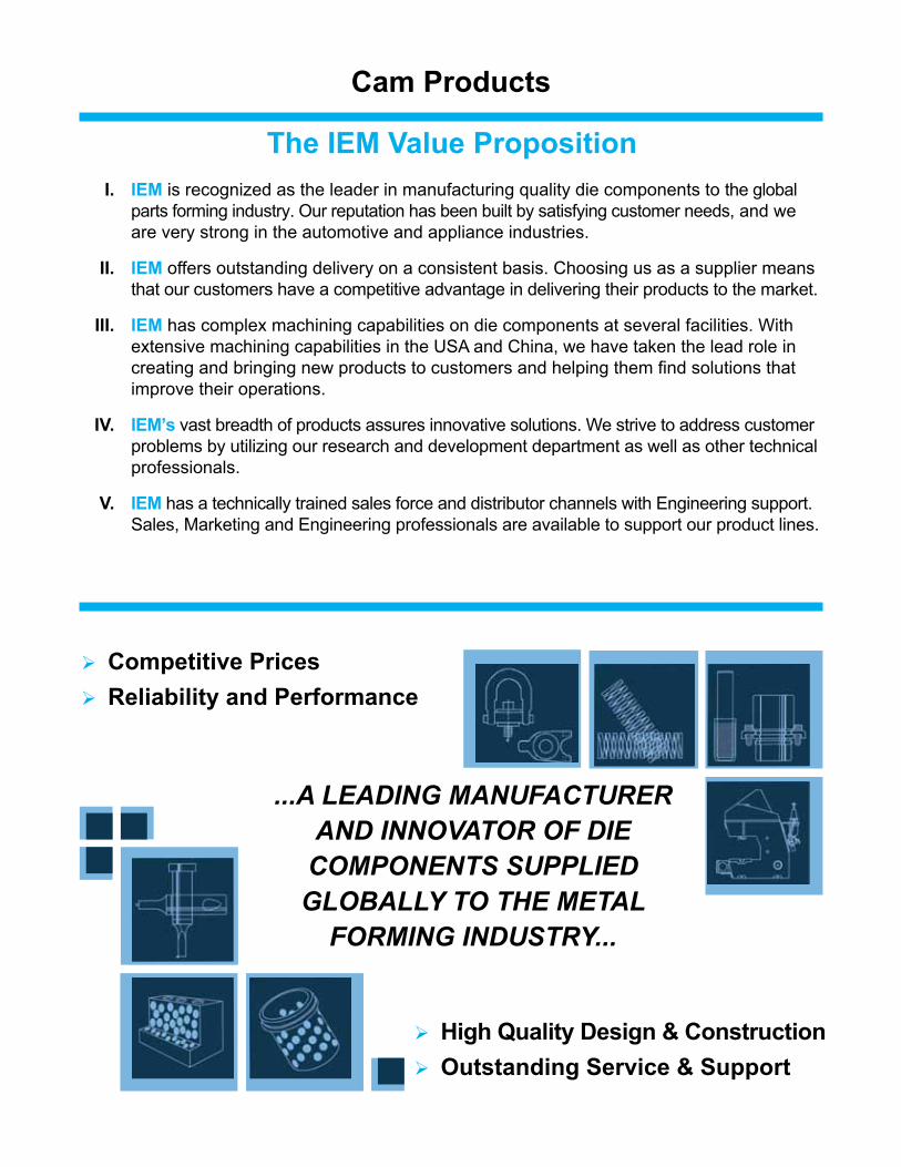
the ieM value Proposition i. ieM is recognized as the leader in manufacturing quality die components to the global parts forming industry. Our reputation has been built by satisfying customer needs, and we are very strong in the automotive and appliance industries.
ii. ieM offers outstanding delivery on a consistent basis. Choosing us as a supplier means that our customers have a competitive advantage in delivering their products to the market.
iii. ieM has complex machining capabilities on die components at several facilities. With extensive machining capabilities in the USA and China, we have taken the lead role in creating and bringing new products to customers and helping them find solutions that improve their operations.
iv. ieM’s vast breadth of products assures innovative solutions. We strive to address customer problems by utilizing our research and development department as well as other technical professionals.
v. ieM has a technically trained sales force and distributor channels with Engineering support. Sales, Marketing and Engineering professionals are available to support our product lines.
...A LEADING MANUFACTURER AND INNOVATOR OF DIE COMPONENTS SUPPLIED GLOBALLY TO THE METAL
FORMING INDUSTRY...
Competitive Pricesreliability and Performance
High Quality Design & ConstructionOutstanding Service & Support

© 2018 Dayton Lamina Corporation. All rights reserved.
Commitment to Quality & Customer Satisfaction
Dayton Lamina is a leading manufacturer of tool, die and mold components for the metal-working and plastics industries. As a customer-focused, world-class supplier of choice, we provide the brands, product breadth, distribution network and technical support for all your metal forming needs.
Our goal is to give our customers the most innovative and value-added products and services.
www.daytonlamina.com
*
*Dayton Lamina’s line of Danly products is available only to North America.
DS 401 1/19