boring operation
7
Store Ca lculators Newsl etters Event s Buye rs' Guide Adverti se Jul 27, 2010 Tweet COMMENTS 0 An adjus table bori ng bar for making precision holes. (Photo by courtesy of National Acme C o. div. of DeVlieg- Bullard Inc.) Cutting Tool Applications Chapter 10: Boring Operations and Machines Boring increases the inside diameter of a hole, and achieves three things: sizing, straightness, and concentricity. George Schneider | American Machinist Boring increases the inside diameter of a hole, and achieves three things: sizing, straightness, and concentricity. Boring, also called internal turning, is used to increase the inside diameter of a hole. The original hole is made with a drill, or it may be a cored hole in a casting. Boring achieves three things: Sizing: Boring brings the hole to the proper size and finish. A drill or reamer can only be used if the desired size is "standard" or if special tools are ground. The boring tool can work to any diameter and it will give the required finish by adjusting speed, feed and nose radius. Precision holes can be bored using microadjustable boring bars. Straightness: Boring will straighten the original drilled or cast hole. Drills, especially the longer ones, may wander off-center and cut at a slight angle because of eccentric forces on the drill, occasional hard spots in the material, or uneven sharpening of the drill. Cored holes in castings are almost never completely straight. The boring tool being moved straight along the ways with the carriage feed will correct these errors. Concentricity: Boring will make the hole concentric with the outside diameter within the limits of the accuracy of the chuck or holding device. For best concentricity, the turning of the outside diameter and the boring of the inside diameter is done in one set-up-that is, without moving the work between operations. The basics of turning, discussed in Chapter 4 and Chapter 5, also apply to boring. However, with boring there are a number of limitations that must be taken into account in order to reach a high stock removal rate combined with satisfactory accuracy, surface finish and tool life. Therefore, in this chapter the limitations that distinguish internal turning from external turning will be discussed in greater JAN 8, 2015 Latest News Boeing, Airbus Win Satellite Contracts from SES Late-Year Rise in Demand Noted for Cutting Tools German Machine Tool Output Slipped in 2014, but Demand Now Rising GE Notes Success with CMC for Engine Rotating Parts December Machine Tool Orders Deliver 2014 Into Positive Territory More White Papers & Manufacturing eBooks WHITE PAPER Ventana Research Perspective In today’s environment, mobile solutions are seen as core drivers of organizations pushing to gain operational efficiencies over their competitors. Learn how utilizing ERP software with modern mobile device capabilities provides a measurable influence on quality and efficiency for manufacturers. This detailed Ventana Research HOME >MACHINING / CUTTING > CUTTING TOOL APPLICATIONS CHAPTER 10: ORING OPERATIONS AND MACHINES SHARE SHARE Machining/Cutting Cutting Tools Automation Enterprise Software QC and Inspection Shop Operations CAD/CAM Software RE GI STER LOG I N Cuttin g Too l Applicatio ns Chapter 10: Borin g Operation s and Machines ... http://a merica nmachi nist.co m/machi ning-cu tting/c utting-t ool-ap plicati on... 1 of 7 2/18/2015 11:54 PM
-
Upload
beth-walker -
Category
Documents
-
view
16 -
download
0
description
boring operation using boring bar
Transcript of boring operation
7/18/2019 boring operation
http://slidepdf.com/reader/full/boring-operation-569bcdfb31e1d 1/7
Store Calculators Newsletters Events Buyers' Guide Advertise
Jul 27, 2010
Tweet COMMENTS 0
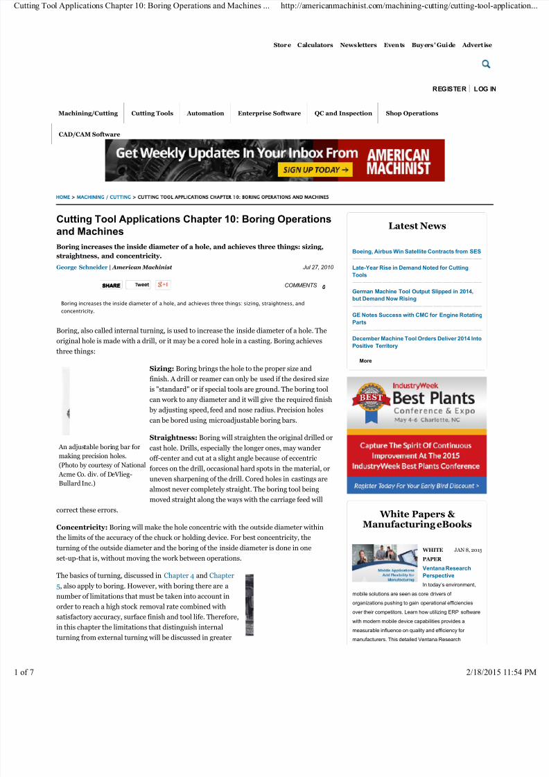
An adjustable boring bar for
making precision holes.
(Photo by courtesy of National
Acme Co. div. of DeVlieg-
Bullard Inc.)
Cutting Tool Applications Chapter 10: Boring Operations
and Machines
Boring increases the inside diameter of a hole, and achieves three things: sizing,
straightness, and concentricity.
George Schneider | American Machinist
Boring increases the inside diameter of a hole, and achieves three things: sizing, straightness, and
concentricity.
Boring, also called internal turning, is used to increase the inside diameter of a hole. The
original hole is made with a drill, or it may be a cored hole in a casting. Boring achieves
three things:
Sizing: Boring brings the hole to the proper size and
finish. A drill or reamer can only be used if the desired size
is "standard" or if special tools are ground. The boring toolcan work to any diameter and it will give the required finish
by adjusting speed, feed and nose radius. Precision holes
can be bored using microadjustable boring bars.
Straightness: Boring will straighten the original drilled or
cast hole. Drills, especially the longer ones, may wander
off-center and cut at a slight angle because of eccentric
forces on the drill, occasional hard spots in the material, or
uneven sharpening of the drill. Cored holes in castings are
almost never completely straight. The boring tool being
moved straight along the ways with the carriage feed will
correct these errors.
Concentricity: Boring will make the hole concentric with the outside diameter within
the limits of the accuracy of the chuck or holding device. For best concentricity, the
turning of the outside diameter and the boring of the inside diameter is done in one
set-up-that is, without moving the work between operations.
The basics of turning, discussed in Chapter 4 and Chapter
5, also apply to boring. However, with boring there are a
number of limitations that must be taken into account in
order to reach a high stock removal rate combined with
satisfactory accuracy, surface finish and tool life. Therefore,
in this chapter the limitations that distinguish internal
turning from external turning will be discussed in greater
JAN 8, 2015
Latest News
Boeing, Airbus Win Satellite Contracts from SES
Late-Year Rise in Demand Noted for Cutting
Tools
German Machine Tool Output Slipped in 2014,
but Demand Now Rising
GE Notes Success with CMC for Engine Rotating
Parts
December Machine Tool Orders Deliver 2014 Into
Positive Territory
More
White Papers &
Manufacturing eBooks
WHITE
PAPER
Ventana Research
Perspective
In today’s environment,
mobile solutions are seen as core drivers of
organizations pushing to gain operational efficiencies
over their competitors. Learn how utilizing ERP software
with modern mobile device capabilities provides a
measurable influence on quality and efficiency for
manufacturers. This detailed Ventana Research
HOME >MACHINING / CUTTING > CUTTING TOOL APPLICATIONS CHAPTER 10: ORING OPERATIONS AND MACHINES
SHARESHARE
Machining/Cutting Cutting Tools Automation Enterprise Software QC and Inspection Shop Operations
CAD/CAM Software
REGISTER LOG IN
ng Tool Applications Chapter 10: Boring Operations and Machines ... http://americanmachinist.com/machining-cutting/cutting-tool-app
2/18/2015
7/18/2019 boring operation
http://slidepdf.com/reader/full/boring-operation-569bcdfb31e1d 2/7
A typical horizontal boring
operation. (Photo by courtesy
of Sandvik Coromant Co.)
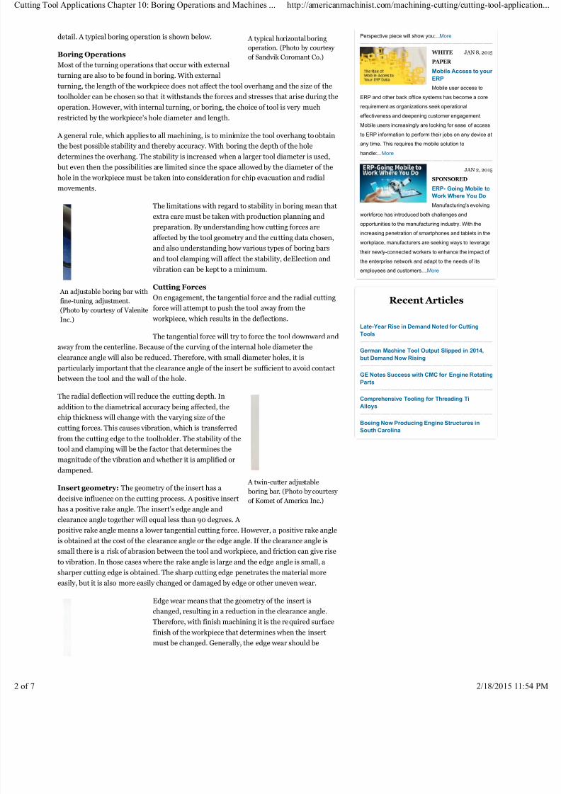
An adjustable boring bar with
fine-tuning adjustment.
(Photo by courtesy of Valenite
Inc.)
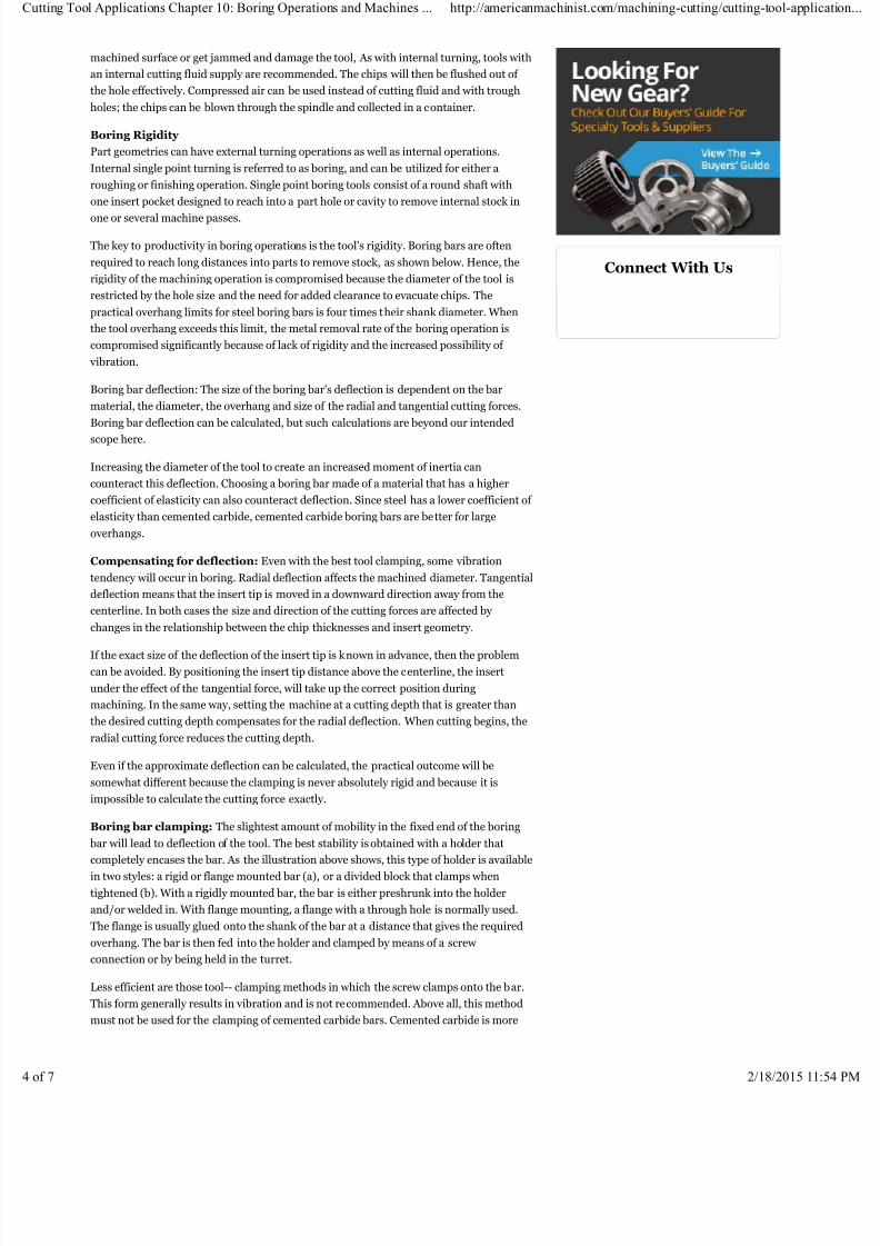
A twin-cutter adjustable
boring bar. (Photo by courtesy
of Komet of America Inc.)
detail. A typical boring operation is shown below.
Boring Operations
Most of the turning operations that occur with external
turning are also to be found in boring. With external
turning, the length of the workpiece does not affect the tool overhang and the size of the
toolholder can be chosen so that it withstands the forces and stresses that arise during the
operation. However, with internal turning, or boring, the choice of tool is very much
restricted by the workpiece's hole diameter and length.
A general rule, which applies to all machining, is to minimize the tool overhang to obtain
the best possible stability and thereby accuracy. With boring the depth of the hole
determines the overhang. The stability is increased when a larger tool diameter is used,
but even then the possibilities are limited since the space allowed by the diameter of the
hole in the workpiece must be taken into consideration for chip evacuation and radial
movements.
The limitations with regard to stability in boring mean that
extra care must be taken with production planning and
preparation. By understanding how cutting forces are
affected by the tool geometry and the cutting data chosen,
and also understanding how various types of boring bars
and tool clamping will affect the stability, deElection and
vibration can be kept to a minimum.
Cutting Forces
On engagement, the tangential force and the radial cutting
force will attempt to push the tool away from the
workpiece, which results in the deflections.
The tangential force will try to force the tool downward and
away from the centerline. Because of the curving of the internal hole diameter the
clearance angle will also be reduced. Therefore, with small diameter holes, it is
particularly important that the clearance angle of the insert be sufficient to avoid contact
between the tool and the wall of the hole.
The radial deflection will reduce the cutting depth. Inaddition to the diametrical accuracy being affected, the
chip thickness will change with the varying size of the
cutting forces. This causes vibration, which is transferred
from the cutting edge to the toolholder. The stability of the
tool and clamping will be the factor that determines the
magnitude of the vibration and whether it is amplified or
dampened.
Insert geometry: The geometry of the insert has a
decisive influence on the cutting process. A positive insert
has a positive rake angle. The insert's edge angle and
clearance angle together will equal less than 90 degrees. A
positive rake angle means a lower tangential cutting force. However, a positive rake angleis obtained at the cost of the clearance angle or the edge angle. If the clearance angle is
small there is a risk of abrasion between the tool and workpiece, and friction can give rise
to vibration. In those cases where the rake angle is large and the edge angle is small, a
sharper cutting edge is obtained. The sharp cutting edge penetrates the material more
easily, but it is also more easily changed or damaged by edge or other uneven wear.
Edge wear means that the geometry of the insert is
changed, resulting in a reduction in the clearance angle.
Therefore, with finish machining it is the required surface
finish of the workpiece that determines when the insert
must be changed. Generally, the edge wear should be
JAN 8, 2015
JAN 2, 2015
Perspective piece will show you:...More
WHITE
PAPER
Mobile Access to your
ERP
Mobile user access to
ERP and other back office systems has become a core
requirement as organizations seek operational
effectiveness and deepening customer engagement.
Mobile users increasingly are looking for ease of access
to ERP information to perform their jobs on any device at
any time. This requires the mobile solution to
handle:...More
SPONSORED
ERP- Going Mobile to
Work Where You Do
Manufacturing's evolving
workforce has introduced both challenges and
opportunities to the manufacturing industry. With the
increasing penetration of smartphones and tablets in the
workplace, manufacturers are seeking ways to leverage
their newly-connected workers to enhance the impact of
the enterprise network and adapt to the needs of its
employees and customers....More
Recent Articles
Late-Year Rise in Demand Noted for Cutting
Tools
German Machine Tool Output Slipped in 2014,
but Demand Now Rising
GE Notes Success with CMC for Engine Rotating
Parts
Comprehensive Tooling for Threading TiAlloys
Boeing Now Producing Engine Structures in
South Carolina
ng Tool Applications Chapter 10: Boring Operations and Machines ... http://americanmachinist.com/machining-cutting/cutting-tool-app
2/18/2015

7/18/2019 boring operation
http://slidepdf.com/reader/full/boring-operation-569bcdfb31e1d 3/7
A large floor-type boring
machine. (Photo by courtesy
of WMW Machinery Co. Inc.)
A large vertical boring
machine. (Photo by courtesy
of WMW Machinery Co. Inc.)
between 0.004 and 0.012 in. for finishing and between
0.012 and 0.040 in. for rough machining.
Lead angle: The lead angle affects the axial and radial
directions of the cutting forces. A small lead angle produces
a large axial cutting force component while a large lead
angle results in a larger cutting force in the radial direction.
The axial cutting force has a minimal negative effect on the operation since the force is
directed along the boring bar. To avoid vibrations, it is consequently advantageous to
choose a small lead angle but, since the lead angle also affects other factors such as the
chip thickness and the direction of the chip flow, a compromise often has to be made.
The main disadvantage of a small lead angle is that the
cutting forces are distributed over a shorter section of the
cutting edge than with a large lead angle. Furthermore, the
cutting edge is exposed to abrupt loading and unloading
when the edge enters and leaves the workpiece. Since
boring is generally done in a pre-machined hole and is
designated as light machining, small lead angles generally
do not cause a problem. Lead angles of 15 degrees or less
are normally recommended. However, at a lead angle of 15
degrees the radial cutting force will be virtually double that
of the cutting force with a 0 degree lead angle. A typical
indexable insert boring bar with a 0-degree lead angle is
shown on the previous page.
Nose radius: The nose radius of the insert also affects the distribution of cutting forces.
The greater the nose radius, the greater the radial and tangential cutting force- and the
emergence of vibration. However, this is not the case with radial cutting forces. The
deflection of the tool in a radial direction is instead affected by the relationship between
the cutting depth and the size of the nose radius. If the cutting depth is smaller than the
nose radius, the radial cutting forces will increase with increased cutting depth. If the
cutting depth is equal to or greater than the size of the nose radius, the radial deflection
will be determined by the lead angle. Thus, it's a good idea to choose a nose radius that is
somewhat smaller than the cutting depth. In this way the radial cutting forces can be kept
to a minimum, while utilizing the advantages of the largest possible nose radius, leadingto a stronger cutting edge, better surface finish and more even pressure on the cutting
edge.
Chip Breaking and Evacuation
Obtaining relatively short, spiral shaped chips is the goal in internal turning. These are
easy to evacuate and do not place such large stresses on the cutting edge when chip
breaking occurs. Hard breaking of the chips-- this is, when short chips are obtained-
demands power and can increase vibration in the boring bar. However, this is preferred
over having long chips, which can make chip evacuation more difficult. Chip breaking is
affected by a number of factors such as the insert geometry, nose radius, lead angle,
cutting depth, feed and cutting speed. Generally, reduced feed and/or increased cutting
speed results in longer chips. The shape of the chip breaker affects the radius of the chip,
where any built-up edge or crater wear can also act as chip breaker. The direction in which the chips flow and the way that they turn in the spiral, is affected by the lead angle
or the combination of cutting depth and nose radius.
The parameters that affect chip control also affect the direction and size of the cutting
force. Therefore, it is necessary to choose a grade and insert geometry that, together with
the selected machining parameters, fulfill the requirements for good chip control. At the
same time, the machine, boring bar and tool clamping must provide sufficient stability in
order to resist the cutting forces that arise.
During boring operations the chip flow can be critical, particularly when deep holes are
being machined. The centrifugal force presses the chips outward. With boring, this means
that the chips remain in the workpiece. The remaining chips could get pressed into the
PrincofMetal
E-MAIL*
COUNTRY*
Sign-up to receive our free newsletters
American Machinist Weekly Update -
(Weekly) View Sample
3D Printing 360 - (Twice-Monthly) View
Sample
Quick Manufacturing News - (Daily)View Sample
IndustryDeck - (Every other month)
View Sample
Enter your email above to receive messages about
offerings by Penton, its brands, affiliates and/or
third-party partners, consistent with Penton’s Privacy
Policy.
Featured Products
Metallurgy Training: Corrosion of
Metals
Learn about the physics of seven
common types of corrosion and methods
for controlling corrosion.
Metallurgy Training: Metallurgy of
Steel Heat Treating
This is a combination of 3 courses:
Metallurgy of Steel, Steel Through
Hardening, and Steel Case Hardening.
Metallurgy Training: Principles of
Metallurgy
Learn how metal composition and
various microscopic structures are
modified to modify metal strength.
VIEW CATALOG VIEW SHOPPING CART
ng Tool Applications Chapter 10: Boring Operations and Machines ... http://americanmachinist.com/machining-cutting/cutting-tool-app
2/18/2015
7/18/2019 boring operation
http://slidepdf.com/reader/full/boring-operation-569bcdfb31e1d 4/7
machined surface or get jammed and damage the tool, As with internal turning, tools with
an internal cutting fluid supply are recommended. The chips will then be flushed out of
the hole effectively. Compressed air can be used instead of cutting fluid and with trough
holes; the chips can be blown through the spindle and collected in a container.
Boring Rigidity
Part geometries can have external turning operations as well as internal operations.
Internal single point turning is referred to as boring, and can be utilized for either a
roughing or finishing operation. Single point boring tools consist of a round shaft with
one insert pocket designed to reach into a part hole or cavity to remove internal stock in
one or several machine passes.
The key to productivity in boring operations is the tool's rigidity. Boring bars are often
required to reach long distances into parts to remove stock, as shown below. Hence, the
rigidity of the machining operation is compromised because the diameter of the tool is
restricted by the hole size and the need for added clearance to evacuate chips. The
practical overhang limits for steel boring bars is four times their shank diameter. When
the tool overhang exceeds this limit, the metal removal rate of the boring operation is
compromised significantly because of lack of rigidity and the increased possibility of
vibration.
Boring bar deflection: The size of the boring bar's deflection is dependent on the bar
material, the diameter, the overhang and size of the radial and tangential cutting forces.
Boring bar deflection can be calculated, but such calculations are beyond our intended
scope here.
Increasing the diameter of the tool to create an increased moment of inertia can
counteract this deflection. Choosing a boring bar made of a material that has a higher
coefficient of elasticity can also counteract deflection. Since steel has a lower coefficient of
elasticity than cemented carbide, cemented carbide boring bars are better for large
overhangs.
Compensating for deflection: Even with the best tool clamping, some vibration
tendency will occur in boring. Radial deflection affects the machined diameter. Tangential
deflection means that the insert tip is moved in a downward direction away from the
centerline. In both cases the size and direction of the cutting forces are affected by
changes in the relationship between the chip thicknesses and insert geometry.
If the exact size of the deflection of the insert tip is known in advance, then the problem
can be avoided. By positioning the insert tip distance above the centerline, the insert
under the effect of the tangential force, will take up the correct position during
machining. In the same way, setting the machine at a cutting depth that is greater than
the desired cutting depth compensates for the radial deflection. When cutting begins, the
radial cutting force reduces the cutting depth.
Even if the approximate deflection can be calculated, the practical outcome will be
somewhat different because the clamping is never absolutely rigid and because it is
impossible to calculate the cutting force exactly.
Boring bar clamping: The slightest amount of mobility in the fixed end of the boring
bar will lead to deflection of the tool. The best stability is obtained with a holder that
completely encases the bar. As the illustration above shows, this type of holder is available
in two styles: a rigid or flange mounted bar (a), or a divided block that clamps when
tightened (b). With a rigidly mounted bar, the bar is either preshrunk into the holder
and/or welded in. With flange mounting, a flange with a through hole is normally used.
The flange is usually glued onto the shank of the bar at a distance that gives the required
overhang. The bar is then fed into the holder and clamped by means of a screw
connection or by being held in the turret.
Less efficient are those tool-- clamping methods in which the screw clamps onto the bar.
This form generally results in vibration and is not recommended. Above all, this method
must not be used for the clamping of cemented carbide bars. Cemented carbide is more
Connect With Us
ng Tool Applications Chapter 10: Boring Operations and Machines ... http://americanmachinist.com/machining-cutting/cutting-tool-app
2/18/2015

7/18/2019 boring operation
http://slidepdf.com/reader/full/boring-operation-569bcdfb31e1d 5/7
brittle than steel and cracks will occur as a result of vibration, which in turn may result in
breakage.
Boring Bars
Boring bars are made in a wide variety of styles. Single-point boring bars are easily
ground but difficult to adjust when they are used in turret and automatic lathes and
machining centers, unless they are held in an adjustable holder. (See illustrations below.)
More expensive boring bars are provided with easily adjustable inserts. These bars are
made in standard sizes, with a range of 0.25 to 0.5 in. on the diameter. A fine adjustment
is included in increments of 0.001 in., or in some cases 0.0001 in. They are standard up to
about 6 in. in diameter. A boring bar with adjustments is shown below.
Many times it may be economical to order special bars with two or more preset diameters,
set at the proper distance apart. These special bars cost more and are generally only used
when large quantities make their use economical. Sometimes this may be the only way to
hold the required tolerances and concentricity.
Other special boring bars, sometimes called boring heads, are designed with replaceable
cartridges.
Boring bar types: Boring bars are available in steel, solid carbide, and carbide-
reinforced steel. The capacity to resist deflection increases as the coefficient of elasticity
increases. Since the elasticity coefficient of carbide is three times larger than that of steel,
carbide bars are preferred for large overhangs. The disadvantage of carbide is its poor
ability to withstand tensile stress. For carbide-reinforced bars, the carbide sleeves are
prestressed to prevent tensile stresses.
Boring bars can be equipped with ducts for internal cooling, which is preferred for
internal turning. An internal coolant supply provides efficient cooling of the cutting edge,
plus better chip breaking and chip evacuation. In this way a longer tool life is obtained
and quality problems, which often arise because of chip jamming, are avoided.
Boring bar choice: When planning production, it is very important to minimize cutting
forces and to create conditions where the greatest possible stability is achieved so that the
tool can withstand the stresses that always arise. The length and diameter of the boring
bar will be of great significance to the stability of the tool. Since the appearance of the
workpiece is the decisive factor when selecting the minimum overhang and maximum
tool diameter that can be used, it is important to choose the tool, tool clamping and
cutting data which minimize, as much as possible, the cutting forces which arise during
the operation.
The following recommendations should be followed to obtain the best possible stability:
• Choose the largest possible bar diameter, but at the same time ensure that there is
enough room for chip evacuation.
• Choose the smallest possible overhang but, at the same time, ensure that the length of
the bar allows the recommended clamping lengths to be achieved.
• A 0-degree lead angle should be used. The lead angle should, under no circumstances be
more than 15 degrees.
• The indexable inserts should be positive rake that results in lower cutting forces.
• The carbide grade should be tougher than for external turning in order to withstand the
stresses to which the insert is exposed when chip jamming and vibration occur.
• Choose a nose radius that is smaller than the cutting depth.
Modern boring bars are designed to take into account the demands that must apply
because the operation is performed internally and the dimensions of the tool are
determined by the hole depth and the hole diameter. With a positive rake insert
geometry, less material deformation and low cutting forces are obtained. The tool should
offer good stability to resist the cutting forces that arise and also to reduce deflection and
vibration as much as possible. Because of space requirements, satisfactory chip control
and good accessibility are also properties of greater importance than with external
turning.
ng Tool Applications Chapter 10: Boring Operations and Machines ... http://americanmachinist.com/machining-cutting/cutting-tool-app
2/18/2015

7/18/2019 boring operation
http://slidepdf.com/reader/full/boring-operation-569bcdfb31e1d 6/7
Boring Machines
Boring operations can be performed on other than boring machines, such as lathes,
milling machines and machining centers. Boring machines, like most other machine
tools, can be classified as horizontal or vertical.
Horizontal Boring Machines (HBM) — The HBM is made to handle medium to very
large-sized parts, but these parts are usually somewhat rectangular in shape, though they
may be asymmetrical or irregular. The available cutting tools only limit the size of cut, the
rigidity of the spindle, and the available horsepower.
The table-type HBM is built on the same principles as the horizontal-spindle milling
machines. The base and column are fastened together, and the column does not move.
The tables are heavy, ribbed castings which may hold loads up to 20,000 pounds.
Size of HBM: The basic size of an HBM is the diameter of the spindle. Table-type
machines usually have spindles from 3 to 6 in. diameter. The larger sizes will transmit
more power and, equally important, the spindle will not sag or deflect as much when
using a heavy cutting tool while extended. The size is further specified by the size of the
table. Although each machine has a "standard" size table, special sizes may be ordered.
The principal parts of the horizontal boring machine are shown below.
Workholding: Workholding is with clamps, bolts or fixtures, the same as with other
machines. Rotary tables allow machining of all four faces of a rectangular part or various
angle cuts on any shape of part. Rotary tables up to 72-in. square or round are used for
large work. If large, rather flat work is to be machined, an angle plate is used. The
workpiece is bolted or clamped onto the angle plate so that the "flat" face is toward the
spindle.
Cutting tools: Cutting tools are held in the rotating spindle by a tapered hole and a
drawbar. To speed up the process of tool changing, either or both of two things are done:
• The drawbar (which pulls the tapered tool holder tightly into the spindle hole) can be
power operated. Thus, the holder is pulled tight or ejected very quickly.
• Quick-change tooling is used. A basic holder is secured in the spindle. It has a taper into
which tools may be secured by a quarter to half turn of the locking collar. Thus, the
operator can change preset tools in 10 to 30 seconds.
Speeds and feeds: Speeds and feeds cover a wide range because of the wide variety of
cutters that may be used on the HBM. Speeds from 15 to 1500 RPM and feed rates from
0.1 to 40 IPM are commonly used.
Floor-type horizontal boring machine (HBM) — The floor type HBM is used for
especially tall or long workpieces. The "standard" 72-in. runway can be made almost any
length required for special jobs. Lengths of 20 feet are in use today. The height of the
column, which is usually 60 to 72 in., can be made to order up to twice this height if the
work requires it.
HBM table: The table is separate from the boring machine though it is, of course,
fastened to the floor. It may be bolted to the runway. The entire column and column base
move left and right (the X axis) along special ways on the runway. The runway must be
carefully aligned and leveled when it is first installed, and then checked at intervals as the
machine is used.
HBM headstock: The headstock can be moved accurately up and down the column (the Y
axis). The 6 to 10 in. diameter spindle rotates to do the machining. It is moved in and out
(the Z axis) up to 48 in. for boring cut, drilling, setting the depth of milling cuts, etc. As in
the table-type HBM, the spindle diameter and table size specify the machine size.
Cutting tools: Cutting tools are the same as those used on the table-type machine.
Workholding is also the same, and angle plates are frequently used.
Vertical Boring Machined (VBM) — A general description of a vertical boring
machine would be that it is a lathe turned on end with the headstock resting on the floor.
This machine is needed because even the largest engine lathes cannot handle work much
over 24 in. in diameter. Today's VBMs are often listed as turning and boring machines. If
facing is added to that name, it pretty well describes the principal uses of this machine.
ng Tool Applications Chapter 10: Boring Operations and Machines ... http://americanmachinist.com/machining-cutting/cutting-tool-app
2/18/2015

7/18/2019 boring operation
http://slidepdf.com/reader/full/boring-operation-569bcdfb31e1d 7/7
Site Features
Media Center
RSS
Sitemap
Site Archive
Newsletters
View Mobile Site
American Machinist Corporate
Privacy Policy
Terms of Service
Contact Us
Follow Us
Search Americanmachinist.com
New Equipment Digest IndustryWeek Material Handling & Logistics Welding Design & Fabrication Forging
Foundry Management & Technology EHS Today Business Finance
Americanmachinist.com
Machining/Cutting Cutting Tools Automation Enterprise Software QC and Inspection Shop Operations CAD/CAM Software
American Machinist Related Sites
Copyright © 2015 Penton
Tweet
Just like any lathe, these machines can make only round cuts plus facing and contouring
cuts.
Jig Borers
Jig borers are vertical boring machines with high precision bearings. They are available in
various sizes and used mainly in tool rooms for machining jigs and fixtures. More
versatile numerically controlled machines are now replacing many jig borers.
George Schneider, Jr., is the author of Cutting Tool Applications, a handbook to machine
tool materials, principles, and designs. He is the Professor Emeritus of Engineering
Technology at Lawrence Technological University, and former Chairman of the Detroit
Chapter of the Society of Manufacturing Engineers.
Please Log In or Register to post comments.
Related Articles
Cutting Tool Applications, Chapter 9: Drilling Methods and Machines
Cutting Tool Applications Chapter 14: Broaches and Broaching
Cutting Tool Applications Chapter 13: Milling Methods & Machines
Cutting Tool Applications Chapter 15: Saws & Sawing
Cutting Tool Applications Chapter 11: Reaming and Tapping
SHARESHARE
ng Tool Applications Chapter 10: Boring Operations and Machines ... http://americanmachinist.com/machining-cutting/cutting-tool-app