Bone Graft Preparation for the Univers Revers™ Modular ...
16
Bone Graft Preparation for the Univers Revers ™ Modular Glenoid System Surgical Technique
Transcript of Bone Graft Preparation for the Univers Revers™ Modular ...

Bone Graft Preparation for the Univers Revers™
Modular Glenoid System Surgical Technique

FPO

Bone Graft Preparation for the Univers Revers™ Modular Glenoid System I 03
IntroductionThe Univers Revers™ Modular Glenoid System (MGS), a complementary addition to the Univers Revers System portfolio, builds upon the design concept of providing options that help surgeons treat their patients better. With the MGS, Arthrex has advanced this mission by providing a multitude of component choices, helping surgeons provide a tailored approach to individual patient needs.
Designed to work only with the Univers Revers humeral components, the MGS is not FDA-cleared for use with any other reverse shoulder arthroplasty system.
Indications/Uses
The Arthrex Univers Revers Modular Glenoid System is indicated for use in a grossly rotator cuff deficient glenohumeral joint with severe arthropathy or a previously failed joint replacement with a gross rotator cuff deficiency. The patient’s joint must be anatomically and structurally suited to receive the selected implant(s), and a functional deltoid muscle is necessary to use the device.
The Arthrex Univers Revers Modular Glenoid System is indicated for primary, fracture, or revision total shoulder replacement for the relief of pain and significant disability due to gross rotator cuff deficiency. The Arthrex Univers Revers Modular Glenoid System is porous coated and is intended for cementless use with the addition of screws for fixation

I Bone Graft Preparation for the Univers Revers™ Modular Glenoid System 04
Humeral Graft HarvestingSurgical Technique
The Univers Revers™ humeral SutureCup and stem are available in 135° and 155° configurations. Depending on which configuration is selected, place the humeral pin placement guide of that same angle onto the proximal humeral head. The humeral axis should be aligned with the pin placement guide handle to ensure the accurate inclination angle of the guide pin. Version rods can also be introduced into the guide shaft, if desired.
While holding the pin guide shaft, drive the 2.8 mm pin through the pin guide until the lateral humeral cortex is engaged. Then remove the pin guide from the humerus.
The bone graft can be fashioned in a 25 mm or 30 mm diameter. If using the Univers Revers 24 mm modular glenoid baseplate, use a 25 mm graft. If using the 28 mm baseplate, use a 30 mm graft.
Introduce the primary reamer from the MGS over the 2.8 mm guide pin. Use the 24 mm reamer if a Ø25 mm graft is desired. Use the 28 mm reamer for a Ø30 mm graft. Conduct reaming on power until congruency between the reamer face and bone in the humeral head is achieved.
Note: There is no positive stop on the primary reamer. Take care to avoid overreaming.
1 2

Bone Graft Preparation for the Univers Revers™ Modular Glenoid System I 05
Select the appropriately sized hole saw (25 mm or 30 mm) and place it over the 2.8 mm guide pin.
Note: We recommend starting the hole saw while it is off-bone. Starting the saw while it is in contact with bone increases the possibility of fracture.
The hole saw contains an integrated central drill, which prepares the graft to accept the central post of the MGS baseplate. Use the inscribed lines on the outside of the hole saw to determine the desired depth, which will help estimate the maximum graft thickness possible. However, where the humeral resection bisects this graft will ultimately determine the maximum graft thickness.
Once the hole saw has been used, remove the guide pin.
Resect the humeral head at the anatomic neck using an oscillating saw.
CAUTION: When resecting the head, it is possible that the vibration from the saw can dislodge the graft from the surrounding humeral bone. Take care to ensure that the graft does not fall during this stage of preparation.
3 4

I Bone Graft Preparation for the Univers Revers™ Modular Glenoid System 06
Glenoid EvaluationSurgical Technique
Bone Graft Instrumentation The glenoid can be evaluated to determine the graft dimensions best suited for the patient. Use the following steps for a reproducible assessment of graft requirements.
Position the glenoid sizer/pin guide from the instrument set onto the glenoid face. Insert the 2.8 mm guide pin through the desired pin trajectory. For more severe glenoid deformities, the glenoid sizer/pin guide may not touch the bone circumferentially.
If reaming the paleo glenoid, introduce the 33 mm flat reamer over the guide pin. To prevent overmedialization of the reamed surface, frequent visual assessment is necessary.
2
1

Bone Graft Preparation for the Univers Revers™ Modular Glenoid System I 07
Configure the glenoid defect gauge based on the graft diameter being used (25 mm or 30 mm configurations are possible). Only insert the angle-measuring leg into the defect gauge at this time.
Align the angle-measuring leg to the slot along the side of the defect gauge marked “ANGLE (A)” (a). Prior to inserting the leg, confirm the slotted angle pointer arm (b) is pointing toward the same side of the defect gauge.
Defect Gauge Assembly Instructions
3a
3b
(b)
(a)

I Bone Graft Preparation for the Univers Revers™ Modular Glenoid System 08
Slide the angle measurement leg down the defect gauge until its t-bar rests on the slotted angle pointer arm (a). Lift the slotted angle pointer arm until the slotted opening allows the t-bar to slide into the channel (b). The angle measurement leg can then be advanced toward the tip of the defect gauge, resulting in a linked relationship between the angle pointer on the defect gauge face and angle measurement leg (c).
Place the glenoid defect gauge instrument over the 2.8 mm guide pin until the central tip and angle measuring leg of the instrument rest on the glenoid surface. Rotate the gauge’s angle measurement leg about the guide pin to align the gauge with the orientation of the bony defect on the glenoid face.
Make an electrocautery mark on the glenoid where the angle measurement leg rests. Make another mark 180° opposed. Keeping the gauge aligned to the electrocautery marks, note the angle measurement from the angle pointer on the lateral aspect of the defect gauge.
3c
4
(a) (b) (c)
Bone Graft Preparation for the Univers Revers™ Modular Glenoid System I 09
Glenoid PreparationSurgical Technique
Select the angled adapter corresponding to the measurement from the glenoid defect gauge (angle) and place it on the reamer sleeve.
Attach the disposable variable angle reamer face into the reamer assembly. A tactile connection should be felt as the reamer face attaches securely to the inner drive shaft.
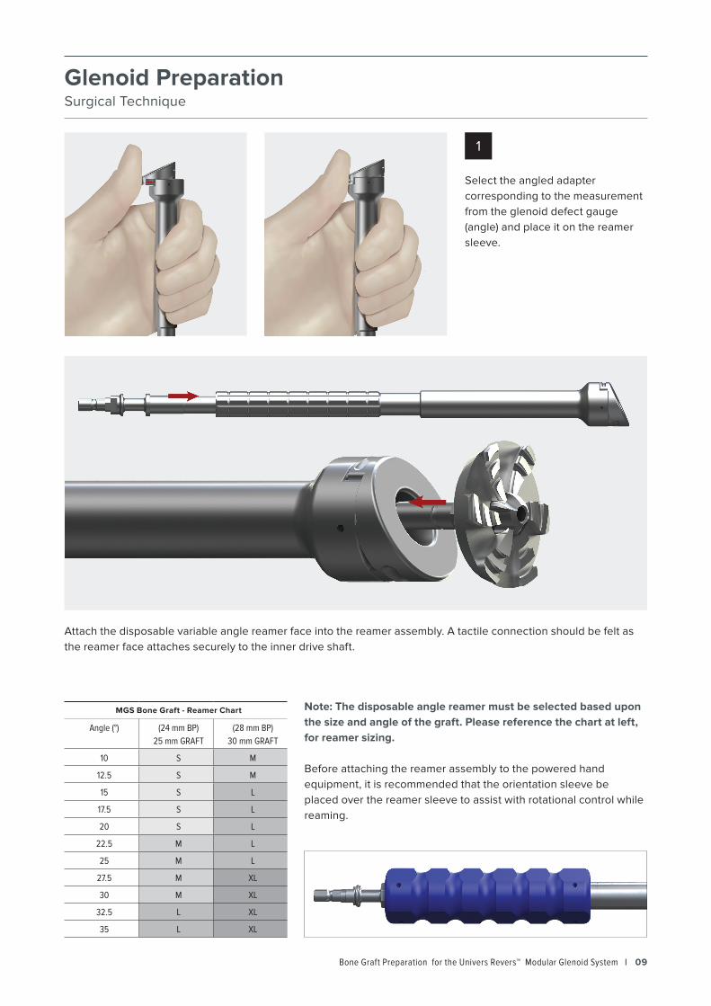
Note: The disposable angle reamer must be selected based upon the size and angle of the graft. Please reference the chart at left, for reamer sizing.
Before attaching the reamer assembly to the powered hand equipment, it is recommended that the orientation sleeve be placed over the reamer sleeve to assist with rotational control while reaming.
MGS Bone Graft - Reamer Chart
Angle (°) (24 mm BP)25 mm GRAFT
(28 mm BP)30 mm GRAFT
10 S M
12.5 S M
15 S L
17.5 S L
20 S L
22.5 M L
25 M L
27.5 M XL
30 M XL
32.5 L XL
35 L XL
1

I Bone Graft Preparation for the Univers Revers™ Modular Glenoid System 10
Insert the reamer assembly over the 2.8 mm guide wire.
CAUTION: It is recommended to start the reamer prior to making contact with the glenoid bone. Starting the reamer on-bone increases the chance of a glenoid bone fracture.
Advance the reamer slowly, checking often to assess the amount of bone being reamed. The resultant reaming should provide a flat, circular surface on the glenoid face.
Insert the thickness measurement leg (a) into the defect gauge by sliding it into the channel opposite to the angled measurement leg that was previously inserted. With both angle and thickness measurement legs inserted, place the defect gauge over the guide wire and use it to confirm the glenoid reaming angle.
Note the reading from the thickness measurement leg (b). Both the thickness and angle measurements will be used to configure the graft cutting station in the subsequent step.
2
3
(b)
(a)

Bone Graft Preparation for the Univers Revers™ Modular Glenoid System I 11
Graft PreparationSurgical Technique
Place the bone graft cylinder into the raise plate corresponding to the graft diameter (25 mm or 30 mm). Once the graft has been inserted, place the raise plate into the graft prep cart, using the trilobe knob within the cart to further secure the graft (a).
Place the graft prep cart into the graft prep station by sliding it from the right (b). Advance the cart until the desired max thickness (as noted in glenoid preparation steps) is aligned between the ruler on the cart and the THICKNESS displayed on the graft prep station. Turn the thumb knob to lock the cart into place (c).
Based on the angle determined during the glenoid evaluation steps, orient the cutting guide of the graft prep station until it matches the desired angle (a). Once the angle is aligned, lock the cutting guide into place by tightening the thumb knob.
Insert an oscillating saw blade through the guide and advance the blade until the entire graft has been cut.
Note: A saw blade with a thickness of 1.27 mm or less is required for use within the cutting guide.
Loosen the locking screw, which secures the graft prep cart, to slide the cart out of the graft prep station. Unscrew the trilobe knob in the graft cart to remove the graft. Gently lift the bone graft from the cart. If desired, dislodge the graft from the raise plate by pressing through the hole in the back of the plate.
2 3
1
(a)
(a) (b)
(c)
I Bone Graft Preparation for the Univers Revers™ Modular Glenoid System 12
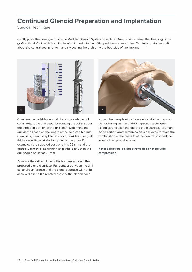
Continued Glenoid Preparation and ImplantationSurgical Technique
Gently place the bone graft onto the Modular Glenoid System baseplate. Orient it in a manner that best aligns the graft to the defect, while keeping in mind the orientation of the peripheral screw holes. Carefully rotate the graft about the central post prior to manually seating the graft onto the backside of the implant.
Combine the variable depth drill and the variable drill collar. Adjust the drill depth by rotating the collar about the threaded portion of the drill shaft. Determine the drill depth based on the length of the selected Modular Glenoid System baseplate post (or screw), less the graft thickness at its most shallow point (at the post). For example, if the selected post length is 25 mm and the graft is 2 mm thick at its thinnest (at the post), then the drill should be set at 23 mm.
Advance the drill until the collar bottoms out onto the prepared glenoid surface. Full contact between the drill collar circumference and the glenoid surface will not be achieved due to the reamed angle of the glenoid face.
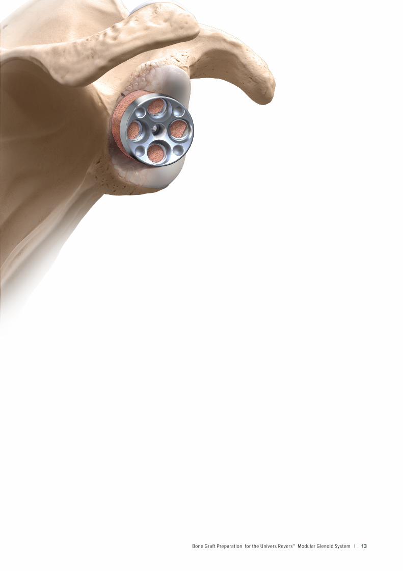
Impact the baseplate/graft assembly into the prepared glenoid using standard MGS impaction technique, taking care to align the graft to the electrocautery mark made earlier. Graft compression is achieved through the combination of the press fit of the central post and the selected peripheral screws.
Note: Selecting locking screws does not provide compression.
1 2
Bone Graft Preparation for the Univers Revers™ Modular Glenoid System I 13

I Bone Graft Preparation for the Univers Revers™ Modular Glenoid System 14
Instrument TrayTop Level
Bottom Level
Bone Graft Preparation for the Univers Revers™ Modular Glenoid System I 15
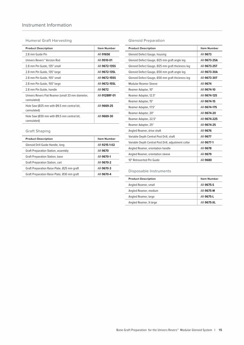
Instrument Information
Humeral Graft Harvesting
Product Description Item Number
2.8 mm Guide Pin AR-9165K
Univers Revers™ Version Rod AR-9510-01
2.8 mm Pin Guide, 135° small AR-9672-135S
2.8 mm Pin Guide, 135° large AR-9672-135L
2.8 mm Pin Guide, 155° small AR-9672-155S
2.8 mm Pin Guide, 155° large AR-9672-155L
2.8 mm Pin Guide, handle AR-9672
Univers Revers Flat Reamer (small 33 mm diameter, cannulated)
AR-9128RF-01
Hole Saw (Ø25 mm with Ø9.5 mm central bit, cannulated)
AR-9669-25
Hole Saw (Ø30 mm with Ø9.5 mm central bit, cannulated)
AR-9669-30
Graft Shaping
Product Description Item Number
Glenoid Drill Guide Handle, long AR-9215-1-02
Graft Preparation Station, assembly AR-9670
Graft Preparation Station, base AR-9670-1
Graft Preparation Station, cart AR-9670-2
Graft Preparation Raise Plate, Ø25 mm graft AR-9670-3
Graft Preparation Raise Plate, Ø30 mm graft AR-9670-4
Glenoid Preparation
Product Description Item Number
Glenoid Defect Gauge, housing AR-9673
Glenoid Defect Gauge, Ø25 mm graft angle leg AR-9673-25A
Glenoid Defect Gauge, Ø25 mm graft thickness leg AR-9673-25T
Glenoid Defect Gauge, Ø30 mm graft angle leg AR-9673-30A
Glenoid Defect Gauge, Ø30 mm graft thickness leg AR-9673-30T
Modular Reamer Sleeve AR-9674
Reamer Adapter, 10° AR-9674-10
Reamer Adapter, 12.5° AR-9674-125
Reamer Adapter, 15° AR-9674-15
Reamer Adapter, 17.5° AR-9674-175
Reamer Adapter, 20° AR-9674-20
Reamer Adapter, 22.5° AR-9674-225
Reamer Adapter, 25° AR-9674-25
Angled Reamer, drive shaft AR-9676
Variable Depth Central Post Drill, shaft AR-9677
Variable Depth Central Post Drill, adjustment collar AR-9677-1
Angled Reamer, orientation handle AR-9678
Angled Reamer, orientation sleeve AR-9679
10° Retroverted Pin Guide AR-9680
Disposable Instruments
Product Description Item Number
Angled Reamer, small AR-9675-S
Angled Reamer, medium AR-9675-M
Angled Reamer, large AR-9675-L
Angled Reamer, X-large AR-9675-XL

This description of technique is provided as an educational tool and clinical aid to assist properly licensed medical professionals in the usage of specific Arthrex products. As part of this professional usage, the medical professional must use their professional judgment in making any final determinations in product usage and technique. In doing so, the medical professional should rely on their own training and experience and should conduct a thorough review of pertinent medical literature and the product’s directions for use. Postoperative management is patient-specific and dependent on the treating professional’s assessment. Individual results will vary and not all patients will experience the same postoperative activity level or outcomes.
View U.S. patent information at www.arthrex.com/corporate/virtual-patent-marking
© 2020 Arthrex, Inc. All rights reserved. | www.arthrex.com | LT1-000047-en-US_B