Thesis PhD Bond Characteristics of Fiber Reinforced Polymers
Bond Behavior of Reinforcing Steel in High Bond Behavior of Reinforcing Steel in High Performance Fiber Reinforced Cement Performance Fiber Reinforced Cement
Composites under Monotonic and Cyclic LoadingComposites under Monotonic and Cyclic Loading
ShihShih--Ho Chao (Post Doctoral Research Fellow )Ho Chao (Post Doctoral Research Fellow )Antoine E. Naaman (Professor)Antoine E. Naaman (Professor)
Gustavo Gustavo ParraParra--MontesinosMontesinos (Associate Professor)(Associate Professor)
Presentation at ACI Convention, Denver, November 5th, 2006Presentation at ACI Convention, Denver, November 5th, 2006

Bond Deterioration (Bond Deterioration (GotoGoto, 1971), 1971)
Bond Failure Mechanism of RC ElementsBond Failure Mechanism of RC Elements
INTRODUCTION
Potential Cone-Shaped Fracture
Internal Bond Crack
TensionTension

Conventional FRC
Single Crack and
Localization
(a)I III
Softening Branch
L/2
A
B
C
strain0
STR
ESS
ccσpcσ
ccεCrack Opening
STR
ESS
ccσ
pcσ
ccεpcε
0δ
Proposed Alternative: (Tensile Strain-Hardening FRC)High-Performance Fiber Reinforced Cement Composites (HPFRCCs)

Direct Tensile TestDirect Tensile Test
Multiple Cracking in HPFRCC Specimen
0 0.2 0.4 0.6 0.8 1 1.2 1.4 1.6
Strain up to Peak Strength(%)
0
400
800
1200
1600
2000
Tens
ileSt
ress
(psi
)
0
2
4
6
8
10
12
Tens
ileSt
ress
(MPa
)
T
T
L+ΔLcf ′= 76 MPa
fV = 2% SquareTwisted Fiber
Spectra FiberHooked Fiber
PVA Fiber
RectangularTwisted Fiber
Single Crack in Regular Concrete Specimen
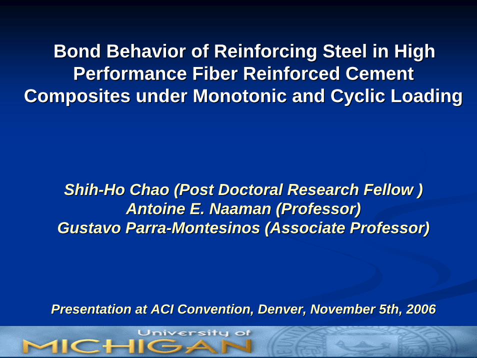
Test Setup and Loading TypeP
(Load)
D (Displacement)
Monotonic Loading
Reinforcing BarReinforcing Bar
HPFRCCHPFRCCPrismPrism
Corner PlateCorner Plate

Reinforcing Bars - Performance Under Monotonic Loading
0 0.2 0.4 0.6 0.8 10.1 0.3 0.5 0.7 0.9Slip (in.)
0
4000
8000
12000
16000
20000
2000
6000
10000
14000
18000
0
300
600
900
1200
1500
150
450
750
1050
1350
Control
Specimen with No. 8 Bar2% Fiber Volume Fraction
Matrix Compressive strength = 11 ksi
Conventional FRC (Steel Hooked Fiber)
Spiral Reinforcement ( = 2%)sρ
HPFRCC (Spectra Fiber)

Load
(lbs)
Aver
age
Bond
Stre
ss(p
si)
sρ
Load
(lbs)
Aver
age
Bond
Stre
ss(p
si)
Unidirectional Force-Controlled Cyclic Loading (Typical Results)
HPFRCC (2% twisted steel fiber)
RC (2% spiral reinforcement)

Fully Reversed Force-Controlled Cyclic Loading (Typical Results)
Control
HPFRCC (2% twisted steel fiber)
RC (2% Spiral)
-0.4 0 0.4-0.6 -0.2 0.2 0.6Slip (in.)
-20000
0
20000
-15000
-10000
-5000
5000
10000
15000
Load
(lbs)
-1200
0
1200
-1500
-900
-600
-300
300
600
900
1500
Aver
age
Bond
Stre
ss(p
si)
Monotonic Curve
sρ14 cycles
26 cycles

Regular Concrete RC (2% Steel Spiral Reinforcement)
Typical Cracking Patterns
HPFRCC (2% Twisted Steel Fiber)
Reinforcing Bars - Performance Under Monotonic Loading

Unfavorable Conditions for Bond Resistance in a Beam-Column Joint
1T
Cone-shaped fracture
2SC2T
1SC
Splitting cracks along beam bars
Diagonal tension cracking
Effective anchorage length
Splitting cracks in front of lugs

Proposed Solution (Material Solution): Use of HPFRCCs in Beam-Column Joints
HPFRCC

Reinforcement:Reinforcement:
Anchorage Length = Anchorage Length = 18.7d18.7dbb
Complete Elimination of Complete Elimination of Confinement in Joint RegionConfinement in Joint Region
Conventional BeamConventional Beam--Column Column Joint (CRSI, 2003)Joint (CRSI, 2003)ACI 318 & ACIACI 318 & ACI--ASCE 352: ASCE 352:
Minimum Anchorage Length = Minimum Anchorage Length = 20d20dbb (still cannot prevent bond deterioration unless 28d28dbb is provided: Leon, 1989)
Heavy Confinement
HPFRCC BeamHPFRCC Beam--Column Joints Column Joints Evaluated in This Study:Evaluated in This Study:
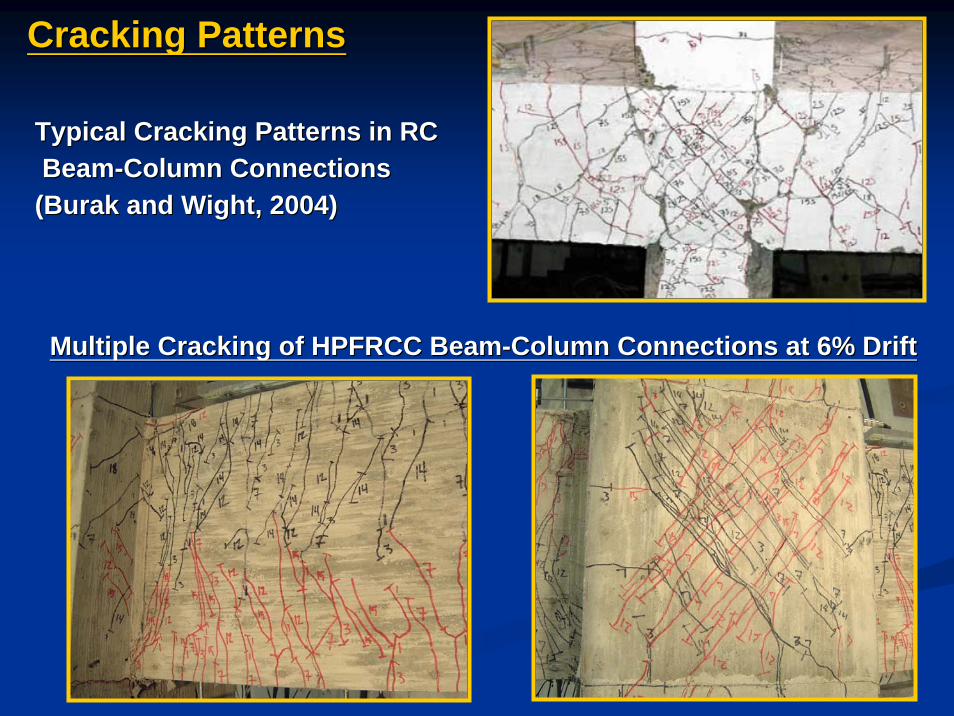
Multiple Cracking of HPFRCC BeamMultiple Cracking of HPFRCC Beam--Column Connections at 6% DriftColumn Connections at 6% Drift
Typical Cracking Patterns in RCTypical Cracking Patterns in RCBeamBeam--Column Connections Column Connections
((BurakBurak and Wight, 2004)and Wight, 2004)
Cracking PatternsCracking Patterns

8 8 10.9
BBN1 BBN3 BBN4 BBN5 BBN7
1
10.9
Specimen 2
EAST WEST
-80
-60
-40
-20
0
20
40
60
80
100
Stee
lStr
ess
(ksi
)
-400
-200
0
200
400
600
Stee
lStre
ss(M
Pa)yσ
0.5% Drift1.0% Drift1.5% Drift2.0% Drift2.5% Drift3.0% Drift4.0% Drift5.0% Drift6.0% Drift
East Beam
Joint
West Beam
BBN1 BBN3 BBN4 BBN5 BBN7
0.0
0.5
1.0
1.5
2.0
2.5
3.0
Aver
age
Bond
Stre
ss(k
si)
0
5
10
15
20
Aver
age
Bon
dSt
ress
(MP
a)
0.5% Drift1.0% Drift1.5% Drift2.0% Drift2.5% Drift3.0% Drift4.0% Drift5.0% Drift6.0% Drift
BBN1|
BBN3
BBN4|
BBN5
BBN5|
BBN7
BBN3|
BBN4
East Beam Joint West Beam
Bond Stress Distribution at Bond Stress Distribution at various drift levelsvarious drift levels
Steel Stress Distribution at Steel Stress Distribution at various drift levelsvarious drift levels
Negligible bar slippage Negligible bar slippage (less than 0.03 in.)(less than 0.03 in.)
Bond Stresses Bond Stresses (Distribution)(Distribution)
Average Bond Stress = 10 Average Bond Stress = 10 MPa (5 MPa for Typical MPa (5 MPa for Typical RC BeamRC Beam--Column Joint)Column Joint)

With same reinforcement amount (volume fraction), HPFRCCs can completely replace conventional transverse reinforcement and show much better performance, in terms of peak bond strength and cracking control. The ACI requirement for development length (assuming 2% spiral) can be reduced by 50% using HPFRCCs without any transverse reinforcement.
Complete elimination of joint transverse reinforcement while maintaining excellent bond response can be achieved by using HPFRCC materials. No bond strength degradation was observed up to a beam plastic hinge rotation of 0.04 radian (0.015 bar strain). This suggests that no repair technique, such as epoxy injection,might be needed for the restoration of bond after a major earthquake.
In SummaryIn Summary……