Bomb Blast Facility Protection for Security, Risk, and ...
67
Bomb Blast Facility Protection for Security, Risk, and Property Managers GSX 2021 Orlando, Florida Wednesday September 29, 2021
Transcript of Bomb Blast Facility Protection for Security, Risk, and ...

Bomb Blast Facility Protection for Security, Risk, and Property Managers
GSX 2021
Orlando, Florida
Wednesday September 29, 2021

• Stephen L Morgan PSP• Project Director, Innovative Engineering Inc.• Education
• BSCET, Southern Polytechnic State University• Security Engineering: USACE Protective Design
Center• Interagency Security Committee (ISC) Risk
management Process: Applied Research Associates (ARA)
• “Design of Blast Resistant Structures” presented by Baker Risk, Houston Texas, Virginia
• “Blast Resistance by Design” Stone Security Engineering
• Experience: 16 Years Security Engineering• Expertise
• Risk Assessments• Site Layout• Physical Security Peer Reviews• Blast Design• Progressive Collapse
Today’s Presenters

• Scott L Weiland PE SE• Principal, Innovative Engineering Inc.• Education
• BSCE University of Michigan• Graduate Studies in Structural Dynamics:
• San Jose State University• Georgia Institute of Technology
• Security Engineering: USACE Protective Design Center
• Interagency Security Committee (ISC) Risk Management Process: ARA
• Counter Terrorism Workshop for Improvised Explosive Devices (IED) and Vehicle-Borne Improvised Explosive Devices (VBIED) -Department of Homeland Security (DHS)
• Registration: PE in 38 States + PR & GU• Experience
• 41 Years Design and Construction• 26 Years Physical Security Engineering
Today’s Presenters

Learning Objectives
• Basis for security criteria
• Risk assessment process and how to develop design criteria
• Blast Design fundamentals
• Progressive Collapse prevention
• How to minimize the impact on the cost of new and renovated
construction

Physical Security Basics

Physical Security Basics
• Concentric Levels of Protection• Progressively reduces the threat as the distance to the asset
decreases
• All of the individual protections form a Protective System
Outer Curtain
Wall
Inner Curtain
Wall
Drum Tower
Inner Gate
Outer Gate
Tower
Moat
Inner
Ward
Outer Ward

Protective System
Protective System Functions
Detect Delay or Defeat Respond
•Electronic Security System
-Intrusion detection
-Alarm communication
-Alarm assessment
-Access control
• Security Forces
• Security Lighting
• Facility Personnel
• Responsible Citizens
• Barriers
- Fences
- Facility roof,
walls, and floors
- Doors
- Windows
- Locks
• Distance
• Vegetation
• Procedures
•Interruption
-Communication
to response force
-Deployment of
response force
-Neutralization

Development of the Protective System

• Prominent Prescriptive Design Criteria
• DoD Minimum Antiterrorism Standards for Buildings, UFC 4-010-01
• VA Physical Security and Resiliency Design Manual (PSRDM)
• UFC 4-010-01 and VA PSRDM are both minimum standards deemed acceptable by Risk Assessments previously conducted. There are instances particularly within DoD where risk assessments determined threats beyond the scope of UFC 4-010-01
Prescriptive Physical Security Criteria
Risk Assessment Process

Risk Assessment Basics
• Asset• Tangible and Intangible
• Supports building function
• Degree of debilitating impact if damaged or destroyed.
• Threat• Aggressor
• Existence
• Capability
• History
• Intentions
• Targeting
• Weapons, tools and tactics
• Vulnerability• Weaknesses that can be exploited

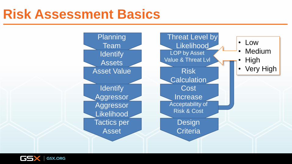
Risk Assessment Basics
Planning
Team
FormationIdentify
AssetsAsset Value
Identify
AggressorAggressor
LikelihoodTactics per
Asset
Threat Level by
Likelihood LOP by Asset
Value & Threat Lvl
Risk
CalculationCost
IncreaseAcceptability of
Risk & Cost
Design
Criteria

Risk Assessment Basics
Planning
Team
FormationIdentify
AssetsAsset Value
Identify
AggressorAggressor
LikelihoodTactics per
Asset
Threat Level by
Likelihood LOP by Asset
Value &
Threat LvlRisk
CalculationCost
IncreaseAcceptability of
Risk & Cost
Design
Criteria
Protective Design Consultant
Building Owner
Tenant
Security
Site management
Key Function Representatives

Risk Assessment Basics
Planning
Team
FormationIdentify
AssetsAsset Value
Identify
AggressorAggressor
LikelihoodTactics per
Asset
Threat Level by
Likelihood LOP by Asset
Value &
Threat LvlRisk
CalculationCost
IncreaseAcceptability of
Risk & Cost
Design
Criteria
• Tangible
• Intangible

Risk Assessment Basics
Planning
Team
FormationIdentify
AssetsAsset Value
Identify
AggressorAggressor
LikelihoodTactics per
Asset
Threat Level by
Likelihood LOP by Asset
Value &
Threat LvlRisk
CalculationCost
IncreaseAcceptability
of Risk &
CostDesign
Criteria
• Critical to User
• Population Type
• Impact on
National
Defense
• Replaceability
• Political
Sensitivity
• Relative Value to
User

Risk Assessment Basics
Planning
Team
FormationIdentify
AssetsAsset Value
Identify
AggressorAggressor
LikelihoodTactics per
Asset
Threat Level by
Likelihood LOP by Asset Value
& Threat Lvl
Risk
CalculationCost
IncreaseAcceptability
of Risk &
CostDesign
Criteria
• Criminals
• Protestors
• Terrorists
• Subversives

Risk Assessment Basics
Planning
Team
FormationIdentify
AssetsAsset Value
Identify
AggressorAggressor
LikelihoodTactics per
Asset
Threat Level by
Likelihood LOP by Asset
Value & Threat Lvl
Risk
CalculationCost
IncreaseAcceptability
of Risk &
CostDesign
Criteria
• Likelihood of
Success

Risk Assessment Basics
Planning
Team
FormationIdentify
AssetsAsset Value
Identify
AggressorAggressor
LikelihoodTactics per
Asset
Threat Level by
Likelihood LOP by Asset
Value & Threat Lvl
Risk
CalculationCost
IncreaseAcceptability
of Risk &
CostDesign
Criteria
• Explosives & Incendiary
Devices
• Standoff Weapons
• Entry
• Surveillance &
Eavesdropping
• Contamination
• Waterfront attack

Risk Assessment Basics
Planning
Team
FormationIdentify
AssetsAsset Value
Identify
AggressorAggressor
LikelihoodTactics per
Asset
Threat Level by
Likelihood LOP by Asset
Value & Threat Lvl
Risk
CalculationCost
IncreaseAcceptability of
Risk & Cost
Design
Criteria
• Severity of
Attacks
• Low
• Moderate
• Significant
• High
Risk Assessment Basics
Planning
Team
FormationIdentify
AssetsAsset Value
Identify
AggressorAggressor
LikelihoodTactics per
Asset
Threat Level by
Likelihood LOP by Asset
Value & Threat Lvl
Risk
CalculationCost
IncreaseAcceptability of
Risk & Cost
Design
Criteria
• Low
• Medium
• High
• Very High

Risk Assessment Basics
Planning
Team
FormationIdentify
AssetsAsset Value
Identify
AggressorAggressor
LikelihoodTactics per
Asset
Threat Level by
Likelihood LOP by Asset
Value & Threat Lvl
Risk
CalculationCost
IncreaseAcceptability of
Risk & Cost
Design
Criteria
Asset Value x
Threat Rating x
Vulnerability
Rating

Risk Assessment Basics
Planning
Team
FormationIdentify
AssetsAsset Value
Identify
AggressorAggressor
LikelihoodTactics per
Asset
Threat Level by
Likelihood LOP by Asset
Value & Threat Lvl
Risk
CalculationCost
IncreaseAcceptability of
Risk & Cost
Design
Criteria
Cost of
countermeasures

Risk Assessment Basics
Planning
Team
FormationIdentify
AssetsAsset Value
Identify
AggressorAggressor
LikelihoodTactics per
Asset
Threat Level by
Likelihood LOP by Asset
Value & Threat Lvl
Risk
CalculationCost
IncreaseAcceptability of
Risk & Cost
Design
Criteria
If not
acceptable
adjust:
• LOP
• Threat

Risk Assessment Process
Risk = Asset Value x Threat Rating x Vulnerability RatingSource: FEMA 426
Asset
Value
Vulnerability
Threat
Risk
Assessment/
LOP
Determination
Mitigation
OptionsDesign
Criteria
Cost Analysis
Benefit Analysis
Mitigation
Affect on
Value
Mitigation
Affect on
Vulnerability

• Prioritize Risk = Asset Value x Threat x Vulnerability
• Identify Mitigation Options• Reduce value, threat, vulnerability
• Estimate Cost
• Cost-Benefit Analysis• By committee
• Protective Design Consultant
• Building Owner
• Tenant
• Security
• Site management
• Key Function Representatives
• Others
• Codify Design Criteria
Risk Assessment Process
Source: FEMA 426
Some Cost
Reduced Risk
Greatest Cost
Lowest Risk
Risk Management Choices
No Cost
Greatest RiskDo Nothing
Reasonable
Measures
Harden Bldg.

• Prominent Standards• ISC, The Risk Management
Process for Federal Facilities
• DoD Security Engineering Facilities Planning Manual, UFC-4-020-01
• Other Standards• ASIS General Security Risk
Assessment Guideline
• TSA, Recommended Security Guidelines for Airport Planning, Design and Construction
• Results in Physical Security Design Criteria for a given project
Risk Assessment Standards

Blast DesignBlast Design Primer
By Scott L Weiland PE SE

Tactics Used in Terrorist Attacks 1970 - 2018
Source: statista
Bombing/Explosion, 1414
Facility/Infrastructure, 905
Armed Assault, 346
Assassination, 134
Unarmed Assault, 68
Hijacking, 17

High Energy Explosives - PIES
• Power• Battery• Match• Chemical
Reaction
• Explosive• Low
Explosive• High
Explosive• Homemade
Explosive (HME)
• Initiator• Blasting
Cap• Light Bulb
• Switch• Cell
Phone• Timer

Minimize Bomb Threat

Pressure Shock Wave

• Pressures decay
exponentially with time.
• Dynamic, non-linear, time
history analysis.
• Dynamic Pressure (Wind)
Blast Theory – Time History
Source: FEMA 427

• Surface Burst (VBIED)
• Pressure Radiates
• Reflected Pressure
• Refracted Pressure
• Side-On Pressure
Blast Theory – Vehicle Bomb

Blast Theory - Shapes That Affect Blast
Blast Wall Berm
OverhangRe-entrant corners
Blast Wall - CFD
Round Shape

Blast Theory - Distance
Source: FEMA 427
• Blast Pressure Decays with Distance

Khobar Towers
• 20,000 lbs. TNT*
• 80 ft. Stand-Off
Murrah Building
• 4,000 lbs. TNT*
• 15 ft Stand-Off
Blast Theory - Distance

• Shock Wave
• Reflected
Pressure
• Rebound
• Side-On
Pressure
Blast Theory - Explosion

•Shock Wave
•Reflected Pressure Wave
•Rebound
Blast Theory - Explosion
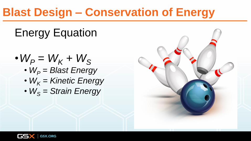
Energy Equation
•WP = WK + WS• WP = Blast Energy
• WK = Kinetic Energy
• WS = Strain Energy
Blast Design – Conservation of Energy

WK = 𝑚
𝑒∗𝑉2
2
Blast Design – Kinetic Energy
Mas
on
ry W
all I
nst
itu
te

•Regions
•Elastic
•Plastic
•Area = Strain Energy
Blast Design – Strain Energy – Ductility

Blast Design – Strain Energy
µ = 1.0 µ > 2.0

• Laminated Glass• 1st Level
• 2 ½”
• Forced Entry Resistant
• Ballistic Resistant
• Blast Resistant
• 2nd & 3rd Level• 2”
• Blast Resistant
Blast Theory – Energy Absorption

Progressive Collapse Prevention
Blast Design Primer

“The spread of an initial local failure from building element to building element, eventually resulting in the collapse of an entire structure or a disproportionately large part of it.”
Progressive Collapse
•Threat Independent
•Not generally required for structures less
than 3 stories
•Mitigation provided by:
•Redundancy
•Local Hardening

• Progressive Collapse• Tie Force Method (Indirect Design Procedure)
• Alternate Path Method (Direct Design Procedure)
Design and Analysis Techniques
Source: UFC 4-023-03
Source: BIPS 05

Design and Analysis Techniques
• Tie Force Method is based primary on bay span and the load carried by the floor/roof level under analysis. Horizontal and vertical ties develop tension capacity to tie the building together to enhance continuity and ductility and provide alternate load paths in the event the primary load path is lost.
• Ties members are limited by the amount of end rotation that can be achieved while still being able to resist the tensile tie force. Generally beams and girders are not used as ties as the amount of end rotation is too great for the member to still resist the given loading
• The tie system consists of internal, peripheral and vertical ties. The internal ties run continuous in each orthogonal direction and are tied to continuous peripheral ties. Vertical ties consist of the building columns or load bearing walls
• Location, continuity, splicing and anchorage of ties are vital in the design of the tie force resisting system.
• Enhanced local resistance design is required for the columns/load bearing walls to resist required shear and flexural design forces

Design and Analysis Techniques
• Alternate Path method is a higher fidelity design procedure which follows the same LRFD design concepts used in seismic design. The analysis is typically conducted with 3 dimensional structural design software
• The alternate path method analysis can be conducted via three approaches. Linear Static Procedure (LSP), Non-Linear Static Procedure (NSP) and Non-Lineal Dynamic Procedure (NDP). Each procedure increases with modeling fidelity and accuracy of predictive results but also increases with complexity of analysis and time associated with the analysis.
• The general procedure is to remove perimeter corner, re-entrant corner, and interior columns/load bearing walls both on the building perimeter and high risk interior area of the building on various levels of the structure and design the primary and secondary members for the resulting force and deformation controlled forces so that progressive collapse will not occur.
• Enhanced local resistance design is required for the columns/load bearing walls to resist required shear and flexural design forces.
• Acceptance, modeling and detailing criteria is highly material dependent.

Implementation of Physical Security Design
Blast Design Primer

Physical Security Involvement
• Some aspect of physical security is required on every project.
• Involvement of a physical security professional should begin at the planning phase of a project with a risk assessment. This ensures that the requirements are clearly in the scope of work and the construction estimate is defined and includes cost for the protective system. Poorly written project scopes that only reference criterion are a major source of change orders and or increased design fees
• During the initiation of the design phase, the design team should have the physical security professional involved to ensure the scope is clearly defined and understood by all parties involved in the design.
• Early involvement both on the planning and design phases of project ensures that both phases are clear on the requirements and do not require future re-work to incorporate the physical security design.

Project Scope Understanding and Clarity
• Clearly understanding the project scope and requirements is the most critical step in ensuring the delivery of the project on budget. Not fully understanding and clarifying the project scope generally leads to either over or under designed protective systems.
• Key questions regarding physical security that must be answered at the beginning of the project
• Is a risk assessment required? If not is there any outcomes of the risk assessment that would fall outside the scope of the governing criteria? If so, what is the governing risk assessment methodology?
• What is the governing physical security criterion for the project?
• Are there any criteria that are local to the installation/facility or to the government agency that are required for use on the project?

Project Scope Understanding and Clarity
• Is the project new construction or modification/renovation/addition to existing construction?
• What is the mission criticality of the facility?
• Will there be intent on future vertical or horizontal expansion. If so, what impact will that have on the facilities mission criticality Ensure all interpretations of the scope of work and criteria related to the scope have been confirmed by the agency prior to commencing the design phase.
• There are grey areas within any criteria that can be open to interpretation. However, the agency having jurisdiction is the final say on the criteria.

• USACE Facility
• Primary body of the scope referenced the minimum standards UFC for the AT/FP requirements.
• Small excerpt referenced a Security Risk Analysis which identified a Medium Level of protection
• Medium level of protection is beyond the minimum standards and beyond what was designed for the project.
• Interpretation was not fully confirmed
Scope Understanding Example

• VA facility
• What is Future Growth?
• Mission criticality went from Life Safety as required by the current project to Mission Critical for the future growth.
• Leads to increased construction and design cost or reduction in programmed space to meet the budget
Poorly Defined Scope Example

Clarity in Construction Documents
• Confusion in the construction documents are generally the biggest attributor to physical security costs and changes during the construction phase of a project.
• The most common issue involves specification of delegated design of vendor products for the protective system. These products are typically windows, doors, glazed curtainwall and non-load bearing light gauge stud wall systems
• The most prevalent problem is specifying the incorrect blast loading criteria, blast loading response and acceptable testing method
• Most A/E firms and delegated designers of vendor products are familiar blast requirements of the UFC (DoD) and ISC (GSA). However, with that familiarity comes misuse on another agency’s project such as with the VA. There are instances where these more available designed and tested system will not work for the VA blast requirements.

• VA Facility
• Performance Specifications for blast resistant windows
Specifications Examples

• VA Facility
• Performance Specifications based on UFC criteria
• 100% incorrect
Specifications Examples

• VA Project
• Performance Specifications based on the correct VA criteria
Specifications Examples

Clarity in Construction Documents
• Another prevalent issue in the construction documents is unclear designation of the protective system on the contract drawings.
• Generally, we see issues where window, door and curtain wall is not designated as blast resistant, and the contractor is left to “interpret” which of these systems are required to be blast resistant. If the contractor interprets wrong their pricing will be incorrect, and the pricing is rarely on the high end of the incorrect spectrum
• Other items that commonly do not get designated on the contract drawings are location of rated vehicle barriers, areas on the site that require no parking designations, incorrect use of straight-line vehicle approaches to the building, incorrect location of drive up drop off canopy structures and correct location of mechanical system intakes to name a few.

• Exterior Glazed openings
• No indication of blast resistance requirements
• Specifications did not indicate blast performance requirements
• All of which lead to changes and cost
Drawing Examples

• Drawing dedicated to showing the required standoff and that all parking and roadways are beyond the minimum standoff required by the VA criteria
• As a reviewer if this is not shown on a drawing it is the first clue that physical security is not a forefront part of the design
Drawing Examples

• Note no standoff distance is shown.
• If shown it would be obvious parking is within the minimum VA standoff.
• Straight line approaches are provided with no means to stop a vehicle.
• Involvement by the PSP didn’t happen until well after 65% design phase.
Drawing Examples

• Drawing dedicated to showing adjacencies required by the VA criteria.
• Great not only for the current project but future renovations that likely will occur
Drawing Examples

• Note no adjacencies shown.
• Violates the VA criteria.
• Critical issue as it affects every discipline on the project and could cause changes to the look of the facility and increase cost
Drawing Examples

• Do’s
• Involve Physical Security Design from the beginning.
• Provide a clear and coordinated project scope
• Fully understand the project scope requirements
• Provide clear and coordinated construction documents.
Physical Security Do’s and Dont’s
• Dont’s
• Use boiler plate scopes of work unless
deemed appropriate by a risk
assessment
• Wait until halfway through a project to
involve physical security design.
• Leave questions or assumptions
regarding the physical security design
unanswered or unverified
• Provide ambiguous and uncoordinated
construction document requirements.

Other Cost Saving Tips
• Standoff distance is your friend! Maximize it! Maximize standoff distance through means of more land or use of access-controlled parking. The cost of access-controlled parking generally is less than the building hardening if not used
• Provide building mass to the building envelope. The mass dampens blast effects and is relatively inexpensive compared to additional hardening.
• Physical security design does not equal BUNKER type construction. The building envelope only needs to be hardened to respond to the required level of protection and no more. Overdesign for blast loading is not only more expensive it can be counterproductive
• Physical security design does not equal Prison/High Security type construction. Use of Crime Prevention Through Environmental Design (CPTED) concepts can provide a more welcome less intrusive facility physical security design. CPTED options are generally less expensive and requires less maintenance and manpower

Scott L Weiland PE SE
Innovative Engineering Inc.
11335 NE 122nd Way
Suite 105
Kirkland, Washington 98034
(206)279-4360, ext. 202
Stephen L Morgan PSP
Innovative Engineering Inc.
3380 Trickum Road
Bldg. 500, Ste 100
Woodstock, Georgia 30188
(678)883-5863
Questions/Contact Information