
BOGOU058
11
ITT Goulds Pumps 3656/3756 S-Group Cast Iron, Bronze Fitted Centrifugal Pumps Bombas centrífugas en hierro fundido con accesorios de bronce Goulds Pumps is a brand of ITT Residential and Commercial Water. Goulds Pumps es una marca de fábrica de ITT Agua Residencial y Comercial. www.goulds.com Engineered for life Commercial Water
-
Upload
jose-gabriel -
Category
Documents
-
view
27 -
download
3
Transcript of BOGOU058

ITTGoulds Pumps3656/3756 S-GroupCast Iron, Bronze Fitted Centrifugal PumpsBombas centrífugas en hierro fundido con accesorios de bronce
Goulds Pumps is a brand of ITT Residential and Commercial Water.
Goulds Pumps es una marca de fábrica de ITT Agua Residencial y Comercial.
www.goulds.com
Engineered for life
Commercial Water

�GOULDS PUMPSCommercial Water
A Full Range of Product Features The 3656 and 3756 S-Group pumps from Goulds have been designed with technical benefits to meet the needs of users in a variety of water supply, recircula-tion, and cooling applications.
• The model 3656 offers close coupled design for space saving and simplified maintenance.
• The model 3756 offers a bear-ing frame mounted design for flexibility of installation and drive arrangements.
• Back pull-out to reduce mainte-nance down time.
• Standard Type 21 mechanical seal for both reliability and availability. Carbon/ceramic/BUNA standard, with other faces and elastomers available.
• 3656/3756 available in all iron, bronze fitted or all bronze construction for application versatility.
• Replaceable wearing compo-nents include stainless steel shaft sleeve and casing and hub wear rings to maintain peak efficiency.
• Packed box sealing is also avail-able as an option.
• Enclosed impeller design, dy-namic balancing and renewable wear rings reduce losses affect-ing performance and pump life.
• Suction and discharge pipe connections are NPT threaded, except 3 x 4 – 7 which has
125 lb. ANSI flat faced flanges.
• Rigid cast iron motor adapter provides support and registered fits maintain positive unit alignment.
• Standard NEMA motor frame, JM or JP shaft extension, C-face mounting, single phase or three phase, 3500 or 1750 RPM. Open drip proof and totally enclosed fan cooled.
• Optional explosion proof or high efficiency motors available.
• Optional rigid carbon steel bedplate, sheet metal coupling guard and T. B. Woods spacer coupling for 3756 models.
Las bombas 3656 y 3756 del Grupo S de Goulds han sido diseñadas con beneficios técnicos para satisfacer las necesidades de los usuarios en variadas aplicaciones de suministro y recirculación de agua y aplicaciones de refrigeración.
• El modelo 3656 cuenta con diseño de acoplamiento corto para ahorrar espacio y simplificar el mantenimiento.
• El modelo 3756 cuenta con diseño de montaje sobre bastidor que ofrece gran flexibilidad en los arreglos de instalación y accionamiento.
• Desmontaje posterior que reduce el tiempo de inactividad por mantenimiento.
• Sello mecánico estándar Tipo 21, brinda gran confiabilidad y asegura la disponibilidad. Estándar de carbono/cerámica/ BUNA, también se encuentran disponibles con otras caras y elastómeros.
• Los modelos 3656 y 3756 se fabrican en todo hierro, con accesorios de bronce o en todo bronce, para una mayor versatilidad de aplicación.
• Los componentes de desgaste reemplazables incluyen los anillos de desgaste de la carcasa y del rodete y la camisa del eje, de acero inoxidable, para mantener la eficiencia pico.
• El diseño de impulsor encerrado, balanceo dinámico y anillos de desgaste reemplazables reducen las pérdidas que afectan el desempeño y la vida de la bomba.
• Las conexiones de succión y descarga son roscadas NPT, con excepción de la bomba de 3 x 4 – 7, que cuenta con bridas de cara lisa ANSI de 125 lbs.
• El adaptador rígido del motor, de hierro fundido, ofrece soporte y los montajes registrados mantienen el alineamiento positivo de la unidad.
• Motor con bastidor NEMA estándar, extensión de eje JM, montaje en cara C, monofásico o trifásico, 3500 ó 1750 RPM. Abierto a prueba de filtraciones o totalmente encerrado enfriado por ventilador.
• Motores a prueba de explosiones y de alta eficiencia disponibles como opción.
• Placa de asiento rígida de acero al carbono, protector de acoplamiento de chapa metálica y acoplamiento espaciador T. B. Woods disponibles como opción en los modelos 3756.
Una amplia gama de variadas características
Goulds Pumps is ISO 9001 Registered.
�GOULDS PUMPSCommercial Water
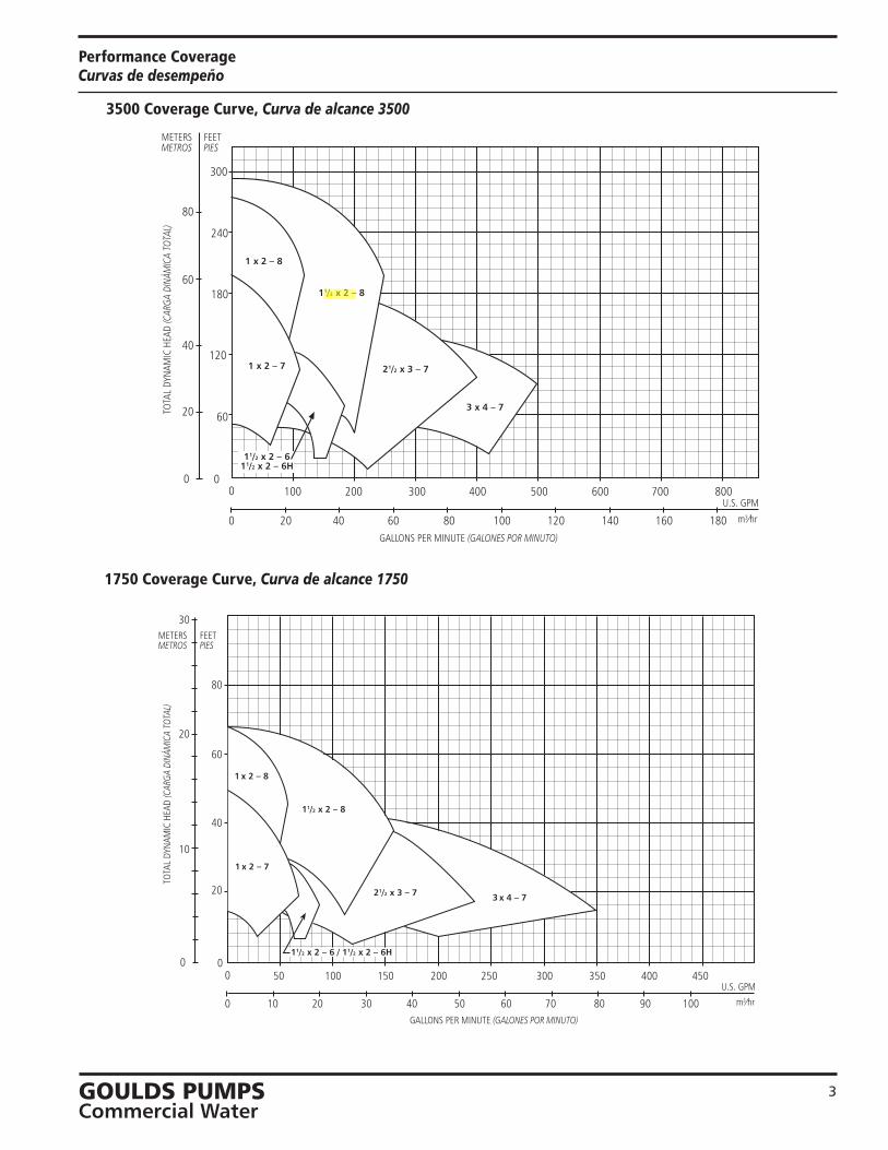
Performance Coverage Curvas de desempeño
60
0
120
180
240
METERSMETROS
0
20
40
60
80
m3⁄hr
U.S. GPM
GALLONS PER MINUTE (GALONES POR MINUTO)
0 10020 6040 80
8003000 100 600400 700200 500
120 140 160 180
TOTA
L DY
NAM
IC H
EAD
(CAR
GA D
INÁM
ICA
TOTA
L)
FEETPIES
11/2 x 2 – 8
300
1 x 2 – 8
1 x 2 – 7 21/2 x 3 – 7
3 x 4 – 7
11/2 x 2 – 611/2 x 2 – 6H
3500 Coverage Curve, Curva de alcance 3500
1750 Coverage Curve, Curva de alcance 1750
0
40
60
80
METERSMETROS
0
10
30
20
m3⁄hr
U.S. GPM
GALLONS PER MINUTE (GALONES POR MINUTO)
0 5010 3020 40
4001500 50 300200 350100 250
60 70 80 90
450
100
20
FEETPIES
TOTA
L DY
NAM
IC H
EAD
(CAR
GA D
INÁM
ICA
TOTA
L)
11/2 x 2 – 8
1 x 2 – 8
1 x 2 – 7
3 x 4 – 721/2 x 3 – 7
11/2 x 2 – 6 / 11/2 x 2 – 6H
Fernando Anchundia
Resaltado

�GOULDS PUMPSCommercial Water
3656/3756 S-Group Numbering System For All Units Built After June 1, 1998Sistema de numeración del Grupo S, modelos 3656/3756, para todas las unidades fabricadas luego del 1° de junio de 1998
The various versions of the 3656 and 3756 S-Group are identified by a prod-uct code number on the pump label. This number is also the catalog number for the pump. The meaning of each digit in the product code number is shown below. Not all combinations of motor, impeller and seal options are available for every pump model. Please check with Goulds on non-cataloged numbers.Not recommended for operation beyond printed H-Q curve. For critical applica-tion conditions consult factory.
Las diferentes versiones de los modelos 3656 y 3756 del Grupo S se identifican con un número de código de producto en la etiqueta de la bomba. Este núme-ro es también el número de catálogo de la bomba. A continuación se ilustra el significado de cada dígito en el código del producto.No todas las combinaciones de motor, impulsor y sellos están disponibles para cada modelo. Consulte a Goulds sobre números que no aparecen en el catálogo.No se recomienda la operación más allá de la curva impresa de H-Q (carga-capacidad). Para aplicaciones bajo condiciones críticas, consulte con la fábrica.
22BF 9BF 3BF 5BF 4BF 6BF 1 x 2 – 7 1 x 2 – 8 1½ x 2 – 6 1½ x 2 – 6H 1½ x 2 – 8 2½ x 3 – 7 3 x 4 – 7 Dia. Dia. Dia. Dia. Dia. Dia. Dia. A 6¾" 81⁄16" 515⁄16" 515⁄16" 81⁄16" 71⁄16" 71⁄16" B 67⁄16 75⁄8 55⁄8 55⁄8 75⁄8 67⁄8 63⁄8 C 6 75⁄16 51⁄8 6¾ 69⁄16 5½ D 5¾ 7 4¾ 5¾ 6 411⁄16
E 5½ 6½ 7¾ 511⁄16 51⁄8 F 51⁄16 63⁄16 7 57⁄16 6 G 413⁄16 53⁄8 6¼ 53⁄16 H 49⁄16 51⁄8 61⁄8 4¾ J 43⁄8 4½ K 41⁄16 41⁄16
L 313⁄16
Driver, Elemento motor1 = 1 PH, fase, ODP 4 = 1PH, fase, TEFC 7 = 3 PH, fases, XP 0 = 1 PH, fase, XP2 = 3 PH, fases, ODP 5 = 3 PH, TEFC 8 = 575 V, XP3 = 575 V, ODP 6 = 575 V, TEFC 9 = 3 PH, fases, TEFC, PREFF1 PH, fase = Monofásico; 3 PH, fases = Trifásico
HP Rating, Potencia nominal, HPC = ½ HP F = 1½ HP J = 5 HP M = 15 HPD = ¾ HP G = 2 HP K = 7½ HP N = 20 HPE = 1 HP H = 3 HP L = 10 HP
Driver: Hertz/Pole/RPM, Elemento motor: Hertz/Polos/RPM1 = 60 Hz, 2 pole, 3500 RPM 4 = 50 Hz, 2 pole, 2900 RPM2 = 60 Hz, 4 pole, 1750 RPM 5 = 50 Hz, 4 pole, 1450 RPM3 = 60 Hz, 6 pole, 1150 RPM
Material, Material BF = Bronze fitted, Accesorios de bronce AI = All iron, Todo hierro AB = All bronze, Todo bronce
Pump Size, Tamaño de bomba3 = 1½ x 2 – 6(H) 5 = 1½ x 2 – 8 9 = 1 x 2 – 8 4 = 2½ x 3 – 7 6 = 3 x 4 – 7 22 = 1 x 2 – 7
Example Product Code, Ejemplo del código de producto
9 BF 1 H 2 G 0
Mechanical Seal and O-ring, Sello mecánico y anillo en O
Impeller Option Code, Código de opción de impulsor
H
High Head Impeller (1½ x 2 – 6H Only), Impulsor de carga alta (1½ x 2 – 6H únicamente)
The 1 x 2 – 8 and 1 x 2 – 7 are only available in Bronze Fitted. Los tamaños 1 x 2 – 8 y 1 x 2 – 7 están disponibles con accesorios de bronce únicamente.
For frame mounted version, substitute the letters “FRM” in these positions.
Para las versiones de montaje en bastidor, reempla-zar las letras en esta ubicación con “FRM”.
Impeller Code,Código del impulsor
0 Carbon,
Ceramic, Cerámica BUNA-N 10K13 1
Carbón Sil-Carbide, EPR 10K19
3 Carburo de Viton 10K27 5 Sil-Carbide silicona 10K64 9 Packed Box Design with BUNA O-Ring, Diseño de prensaestopas empacado con anillo en O de BUNA 15K16
Note: 10K27 replaces obsolete 10K25, Nota: La 10K27 reemplace la obsoleta 10K25.
Seal Code,Código
del Sello
Stationary,Estacionario
Type 21 Mechanical Seal, Tipo 21 sello mecánico
Elastomers,Elastómeros
316 SS,316 Acero inoxidable
Metal Parts,Partes Metálicas
Rotary,Rotativo
Part No.,Pieza
Número
Fernando Anchundia
Resaltado
Fernando Anchundia
Resaltado
Fernando Anchundia
Resaltado
Fernando Anchundia
Resaltado
Fernando Anchundia
Resaltado
Fernando Anchundia
Resaltado
Fernando Anchundia
Resaltado
Fernando Anchundia
Resaltado

�GOULDS PUMPSCommercial Water
Performance Curves – 60 Hz, 3500 RPM Curvas de desempeño – 60 Hz, 3500 RPM
B 75⁄8"
C 63⁄4"
H 61⁄8"
E 73⁄4"
15 HP
% EFF
Model 3656/3756 S-Group 3500 RPM5AI, BF, AB / Size (Tamaño) 11⁄2 x 2 – 8 ODP & TEFCImp. Dwg. 118-88
A 81⁄16" DIA.
50
7 1⁄2 HP
10 HP
10'
5 HP
20 HP
504060
60
65
65
67
70
8'12' 14'
16'
18'
20'22'
F 7"
G 61⁄4"
D 53⁄4"
NPSHR – FEET (PIES)
NOTE: Not recommended for operation beyondprinted H-Q curve.NOTA: No se recomienda la operación más allá de lacurva impresa de H-Q (carga-capacidad).
0
50
100
300
0
20
60
80
0
250150500
10 20 m3⁄ hr
U.S. GPM
60
100 200
30 40 50
250
200
150
40
METERSMETROS
FEETPIES
TOTA
L DY
NAM
IC H
EAD
(CAR
GA D
INÁM
ICA
TOTA
L)
CAPACITY (CAPACIDAD)
Optional ImpellerImpulsor optativo
Ordering Code Dia. Código de pedido Diá.
A 81⁄16" E 7¾" B 75⁄8 F 7 C 6¾ G 6¼ H 61⁄8 D 5¾
NOTE:Pumpwillpassasphereto5⁄16"diameter.NOTA: La bomba dejará pasar una esfera de hasta 5⁄16 de pulgada de diámetro.
00
70
0
250 3000
m3⁄ hr
U.S. GPM350
40
10
20
100
50
200
80
250
200
150
60
50
40
30
20
100
METERSMETROS
FEETPIES
TOTA
L DY
NAM
IC H
EAD
(CAR
GA D
INÁM
ICA
TOTA
L)
CAPACITY (CAPACIDAD)
15050
10 30 6050 70
Model 3656/3756 S-Group 3500 RPM4AI, BF, AB / Size (Tamaño) 21⁄2 x 3 – 7 ODP & TEFCImp. Dwg. 279-81
NOTE: Not recommended for operation beyondprinted H-Q curve.NOTA: No se recomienda la operación más allá de lacurva impresa de H-Q (carga-capacidad).
6' NPSHR – FEET (PIES)8' 10'
D 6''
H 43/4''
% EFF
10 HP
7.5 HP5 HP
15 HP
60
68
64
70
70
12' 14'
16' 18'
A 71/16'' DIA.B 67/8''
F 57/16''
K 41/16''
C 69/16''
E 511/16''
J 41/2''
G 53/16''
7171
64
68
Optional ImpellerImpulsor optativo
Ordering Code Dia. Código de pedido Diá.
A 71⁄16" B 67⁄8 C 69⁄16
D 6 E 511⁄16
F 57⁄16
G 53⁄16
H 4¾ J 4½ K 41⁄16
NOTE:Pumpwillpassasphereto7⁄16"diameter.NOTA: La bomba dejará pasar una esfera de hasta 7⁄16 de pulgada de diámetro.
Fernando Anchundia
Resaltado
Fernando Anchundia
Resaltado
Fernando Anchundia
Resaltado

1�GOULDS PUMPSCommercial Water
3656 S-Group Materials of ConstructionMateriales de construcción - Grupo S, modelo 3756
NOTE:Pumps will be shipped with top-vertical discharge position as standard. For other orientations, remove casing bolts – rotate discharge to desired position – replace and tighten bolts to 25 ft./lbs. Note that discharge may extend below motor mounting surface in bottom-horizontal position; adequate clearance must be provided.
NOTA:Las bombas salen de la fábrica con la des-carga orientada en posición vertical superior de manera estándar. Para modificar la orien-tación, retirar los pernos de la carcasa, hacer girar la descarga hasta la posición deseada y volver a colocar los pernos, ajustándolos a una torsión de 25 pies/libras. Se ha de notar que la descarga se puede extender por debajo de la superficie de montaje del motor en la posición horizontal inferior; por lo tanto, debe proveerse suficiente espacio.
For separate seal housing and adapter construction, all bronze material only, see repair parts page.
Para la construcción separada del compartimiento del sello y el adaptador, materiales de bronce únicamente, con-sulte la página de piezas de repuesto.
1
AISI 1045 steel motor shaft extension (typical)Extensión del eje del motor de acero AISI 1045 (típico)
101
103
383
178
126
198
199
370408
513 108
371
100
Back wearing ring on S-Group (2½ x 3 – 7) onlyAnillo de desgaste posterior en elGrupo S (2½ x 3 – 7) únicamente.
1
Item No. Description
Materials, Materiales
No. Ítem Descripción All Iron Bronze Fitted All Bronze
Todo hierro Accesorios de bronce Todo bronce
100 Casing, Carcasa 1001 101 Impeller, Impulsor 1101
1101
103
Casing wear ring, 1001 1618 1618 Anillo de desgaste de la carcasa
108 Adapter, Adaptador 1001 1001 184 Seal housing, Cubierta del sello One piece with adapter, Una pieza con adaptador 1101 126 Shaft sleeve, Camisa del eje
AISI Type 300 series stainless steel 198 Impeller bolt, Perno del impulsor Acero inoxidable serie AISI tipo 300 199 Impeller washer, Arandela del impulsor 178 Impeller key, Chaveta del impulsor Carbon Steel, Acero al carbono
370 Hex head cap screw (adapter to case), Tornillo de
cabeza hexagonal (del adaptador a la cubierta) Steel SAE 1200 Grade 5
371 Hex head cap screw (adapter to motor), Tornillo de Acero SAE 1200 grado 5
cabeza hexagonal (del adaptador al motor) 383 Mechanical seal, Sello mecánico See seal chart, Ver tabla del sello
408 Pipe plug ¼" or 3⁄8",
Tapón de tubos de ¼ de pulgada ó 3⁄8 de pulgada Steel, Acero Bronze, Bronce
513 O-ring, Anillo en O BUNA-N, BUNA-N
Material Code, Código de material Engineering Standard, Norma de ingeniería
1101 Cast iron ASTM A48 CL20, Hierro fundido ASTM A48 CL20 1101 Silicon bronze ASTM B584, C87500, Siliciuro de bronce ASTM B584, C87500 1618 Bizmuth brass, Latón al bismuto
Packed Box Arrangement, Caja prensaestopas Item No., No. Ítem Description, Descripción Materials, Materiales 105 Lantern ring, Aro de linterna TeflonTM
106
Packing, 5 rings; Teflon Impregnated, Empaquetadura, 5 aros Impregnado de Teflon 107 Gland, Casquillo AISI 316SS 126 Shaft sleeve, Camisa del eje
AISI Type 300 Series Stainless Steel 353 Gland stud, Perno del casquillo
Acero inoxidable serie AISI tipo 300 355 Gland nut, Tuerca del casquillo
105 106 107
353
126
355
PackedBoxArrangementCaja prensaestopas
0 Carbon,
Ceramic, Cerámica BUNA-N 10K13 1
Carbón Sil-Carbide, EPR 10K19
3 Carburo de Viton
10K27 5 Sil-Carbide silicona 10K64 9 Packed Box Design with BUNA O-Ring, Diseño de prensaestopas empacado con anillo en O de BUNA 15K16
Note: 10K27 replaces obsolete 10K25, Nota: La 10K27 reemplace la obsoleta 10K25.
Seal Code,Código
del Sello
Stationary,Estacionario
Type 21 Mechanical Seal, Tipo 21 sello mecánico
Elastomers,Elastómeros
316 SS,316 Acero inoxidable
Metal Parts,Partes Metálicas
Rotary,Rotativo
Part No.,Pieza
Número
1�GOULDS PUMPSCommercial Water
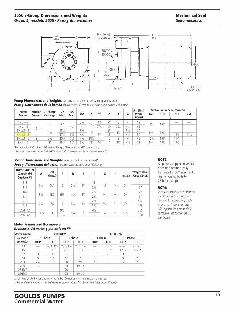
CP DC Wt. (lbs.) Motor Frame Size, Bastidor Pump Suction Discharge
Max. Max. DD R W X Y Z Pesos 140 180 210 250
Bomba Succión Descarga
(libras) L
1 x 2 – 7 1 27
3½ 11⁄16
41⁄8 5½ 3 4 52 10 10¾
— — 1 x 2 – 8
2 4¼ 4 315⁄16 5¾ 33⁄16 4¼ 52 — —
1½ x 2 – 6 1½
23¾ 3½ 1¼
4½ 25⁄8
3½ 34 9¾ 10½
— — 1½ x 2 – 8 271⁄8 53⁄8 45⁄8 4¼ 5 4¼ 54 113⁄8 115⁄8 2½ x 3 – 7 3 2½ 255⁄8 51⁄8 4½ 113⁄16
6 3 4 49 101⁄8 10¾ 11¾ —
3 x 4 – 7 4* 3* 25¼ 5¾ 51⁄8 3¾ 43⁄8 2½ 4½ 82 9¾ 103⁄8 113⁄8 —
3656 S-Group Dimensions and WeightsGrupo S, modelo 3656 - Peso y dimensiones
NOTE:All pumps shipped in vertical discharge position. May be rotated in 90º increments. Tighten casing bolts to 25 ft./lbs. torque.
NOTA:Todas las bombas se embarcan con la descarga en posición vertical. Esta posición puede rotarse en incrementos de 90°. Ajustar los pernos de la carcasa a una torsión de 25 pies/libras.
ABMAX. Z R
X
DG
E EA
1⁄4" NPT
DCMAX
DD
Y W
L F FB
CPMAX.
PMAX.
H - 4 HOLES4 ORIFICIOS
Motor Frame 3500 RPM 1750 RPM Bastidor 1 Phase 3 Phase 1 Phase 3 Phase del motor ODP TEFC ODP TEFC ODP TEFC ODP TEFC 143 — ¾, 1, 1½ ¾, 1, 1½ ¾, 1, 1½ — ½, ¾ ½, ¾, 1 ½, ¾, 1 145 — 2 2, 3 2, 3 — 1, 1½ 1½, 2 1½, 2 182 3 3 5 3 3 2, 3 3 3 184 5 3, 5 7½ 5 — — 5 5 213 7½ — 10 7½ 5 — 7½ 7½ 215 10 — 15 10, 15 — — — — 254TCZ — — 20 — — — — — 256TCZ — — 25 20, 25 — — — —
All dimensions in inches and weights in lbs. Do not use for construction purposes.Todas las dimensiones están en pulgadas, el peso en libras. No utilizar para fines de construcción.
Motor Frames and Horsepower Bastidores del motor y potencia en HP
Pump Dimensions and Weights (Dimension “L” determined by Pump and Motor)Peso y dimensiones de la bomba (la dimensión “L” está determinada por la bomba y el motor)
DISCHARGEDESCARGA
SUCTIONSUCCIÓN
Frame Size JM AB
P Weight (lbs.)
Tamaño del A B D E F G H
(Max.)
bastidor JM (Max.)
Pesos (libras)
143 2 41
145 6½ 5¼ 6 3½ 2¾ 2½
1⁄8 11⁄32 65⁄8
57 182 2¼ 77 184
8½ 57⁄8 6½ 4½ 3¾ 2¾ 3⁄16 13⁄32 77⁄8 97
213 2¾ 122 215
9½ 73⁄8 8 5¼ 4¼ 3½
7⁄32 13⁄32 95⁄8 155 254 TCZ 9½ 41⁄8 265 256 TCZ
11¼ 9 11¾
6¼ 5 5
¼ 17⁄32 11½ 320
Mechanical SealSello mecánico
Motor Dimensions and Weights (may vary with manufacturer)* Peso y dimensiones del motor (pueden variar de acuerdo al fabricante) *
*For use with ANSI class 150 mating flange. All others are NPT connections.* Para uso con brida de contacto ANSI clase 150. Todas las demás son conexiones NTP.
Fernando Anchundia
Resaltado

��GOULDS PUMPSCommercial Water
Specifications Especificaciones Typical Applications Aplicaciones típicas
Capacities to: 550 GPM (125 m3/hr) at 3500 RPM350 GPM (79 m3/hr) at 1750 RPM
Heads to: 280 feet TDH (85 m) at 3500 RPM67 feet TDH (20 m) at 1750 RPM
Working pressure to: 175 PSIG (12 bars)
Suction pressure to:100 PSIG (7 bars)
Maximum temperature to:212°F (100°C) with standard seal or 250°F (121°C) with optional seal.
Motor: NEMA standard JM frame or JP frame for 3656 or T-frame for 3756. Open drip-proof, totally enclosed fan cooled and explo-sion proof enclosures available. Single phase (115/208 – 230 V), ½ to 3 HP (208 – 230 V) 5 HP and (230V only) on 7½, 10 HP. Three phase (208 – 230/460 V) standard note that 20 and 25 HP are (230/460 V).
Direction of Rotation: Clockwise viewed from motor end.
• Booster service
• Spraying systems
• Irrigation
• Water circulation
• Liquid transfer
• General purpose pumping
Capacidad hasta:550 GPM (125 m 3/hr) a 3500 RPM350 GPM (79 m 3/hr) a 1750 RPM
Cargas hasta:280 pies (85 m) carga dinámica total a 3500 RPM67 pies (20 m) carga dinámica total a 1750 RPM
Presión de operación hasta:175 PSIG (12 bars)
Presión de succión hasta:100 PSIG (7 bars)
Temperatura máxima:212 °F (100 °C) con sello estándar o 250 °F (121 °C) con sello optativo.
Motor:Bastidor NEMA JM estándar en el modelo 3656 y bastidor NEMA T estándar en el modelo 3756. Las cubiertas disponibles son: abierta a prueba de filtración, totalmente encerrada con enfriamiento por ventilador y a prueba de explosio-nes. Monofásico (115/208 – 230 V), ½ a 3 HP; (208 – 230 V) 5 HP y (230 V solamente) 7½ a 10 HP. Trifásico (208 – 230/460 V) estándar. Los motores de 20 a 25 HP son de 230/460 V.
Dirección de rotación:Dextrorsa (sentido de las agujas del reloj) cuando se mira desde el extremo del motor.
• Servicio de refuerzo
• Sistemas de rociado
• Sistemas de riego
• Circulación de agua
• Transferencia de líquidos
• Aplicaciones de bombeo en general
ITT Commercial Water
Goulds Pumps and the ITT Engineered Blocks Symbol are registered trademarks and tradenames of ITT Corporation.
Goulds Pumps y el símbolo ITT Engineered Blocks son marcas registradas y marcas comerciales de ITT Corporation.
SPECIFICATIONS ARE SUBJECT TO CHANGE WITHOUT NOTICE.
LAS ESPECIFICACIONES ESTÁN SUJETAS A CAMBIO SIN PREVIO AVISO.
36/3756S October (Octubre), 2006© 2006 ITT Corporation
Engineered for life
ITTGoulds Pumps3656/3756 S, M & L-Group Repair Parts
Goulds Pumps is a brand of ITT Corporation.
www.goulds.com
Engineered for life
Commercial Water
2
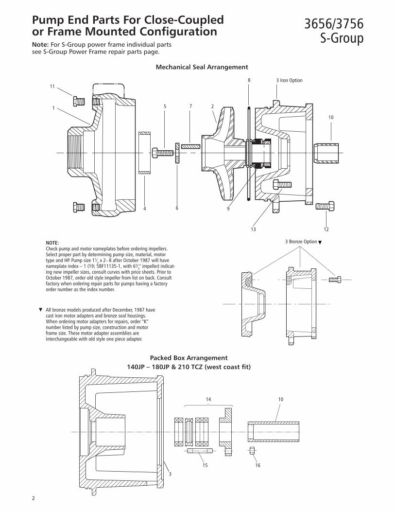
NOTE: Check pump and motor nameplates before ordering impellers. Select proper part by determining pump size, material, motor type and HP. Pump size 11⁄2 x 2–8 after October 1987 will have nameplate index – 1 (19; 5BF11135-1, with 63⁄4" impeller) indicat-ing new impeller sizes, consult curves with price sheets. Prior to October 1987, order old style impeller from list on back. Consult factory when ordering repair parts for pumps having a factory order number as the index number.
▼ All bronze models produced after December, 1987 have cast iron motor adapters and bronze seal housings. When ordering motor adapters for repairs, order “K” number listed by pump size, construction and motor frame size. These motor adapter assemblies are interchangeable with old style one piece adapter.
11
1 5 7 2
8 3 Iron Option
10
1213
964
3 Bronze Option ▼
Mechanical Seal Arrangement
Packed Box Arrangement140JP – 180JP & 210 TCZ (west coast fit)
15 16
14 10
Pump End Parts For Close-Coupled or Frame Mounted Configuration Note: For S-Group power frame individual parts see S-Group Power Frame repair parts page.
3
3656/3756S-Group

3
Repair Part No. 22BF 9BF 3AI/BF/AB 3AIH/BFH/ABH 5AI/BF/AB 4AI/BF/AB 6AI/BF/AB 1 x 2–7 1 x 2–8 1½ x 2–6 1½ x 2–6H 1½ x 2–8 2½ x 3–7 3 x 4–7
1 Casing
Cast Iron 1K365 1K612 1K98 1K102 1K100 1K128 Bronze 1K99 1K103 1K101 1K129 OLD* NEW 2K124 (4.75) 2K154 (5.62) 2K344 (5.75) 2K741 (4.12) 2K1120 (7.06) 2K233 (4.69) 2K122 (5.12) 2K152 (5.94) 2K768 (6.12) 2K740 (4.75) 2K1111 (6.88) 2K232 (5.12) 2K120 (5.62) 2K343 (6.25) 2K739 (4.94) 2K1112 (6.56) 2K230 (5.50) 2K118 (5.94) 2K342 (6.75) 2K738 (5.25) 2K1113 (6.00) 2K229 (6.38) Cast iron 2K341 (7.00) 2K737 (5.44) 2K1114 (5.69) 2K324 (7.06) 2K340 (7.62) 2K736 (5.62) 2K1115 (5.44) 2K339 (7.75) 2K735 (5.88) 2K1116 (5.19) 2K338 (8.06) 2K734 (6.38) 2K1117 (4.75) 2K733 (6.75) 2K1118 (4.50) 2K732 (7.06) 2K1119 (4.06)
2 Impeller 2K815 (3.81) 2K767 (5.12) 2K125 (4.75) 2K155 (5.62) 2K769 (6.12) 2K751 (4.12) 2K1023 (7.06) 2K238 (4.69)
2K814 (4.06) 2K765 (5.38) 2K123 (5.12) 2K153 (5.94) 2K351 (5.75) 2K750 (4.75) 2K1102 (6.88) 2K237 (5.12) 2K813 (4.38) 2K763 (6.19) 2K121 (5.62) 2K350 (6.25) 2K749 (4.94) 2K1103 (6.56) 2K235 (5.50) 2K812 (4.56) 2K761 (6.50) 2K119 (5.94) 2K349 (6.75) 2K748 (5.25) 2K1104 (6.00) 2K234 (6.38) 2K811 (4.81) 2K759 (7.00) 2K348 (7.00) 2K747 (5.44) 2K1105 (5.69) 2K325 (7.06) Sil-Brass 2K810 (5.06) 2K757 (7.31) 2K347 (7.62) 2K746 (5.62) 2K1106 (5.44) 2K809 (5.50) 2K755 (7.62) 2K346 (7.75) 2K745 (5.88) 2K1107 (5.19) 2K808 (5.75) 2K753 (8.06) 2K345 (8.06) 2K744 (6.38) 2K1108 (4.75) 2K807 (6.00) 2K743 (6.75) 2K1109 (4.50) 2K806 (6.44) 2K742 (7.06) 2K1110 (4.06) 2K805 (6.75) Motor adapter – seal Cast iron 1K118 1K114 1K110 1K110 1K114 1K118 1K118 140-180JM and frame mounted Sil-Brass 1K111 1K111 1K115 1K119 1K119
(210JM), (256TCZ) Cast iron 1K120 1K116 1K112 1K112 1K116 1K120 1K120
3 Sil-Brass 1K113 1K113 1K117 1K121 1K121 Motor adapter – packing (140- Cast iron 1K369 1K371 1K367 1K367 1K371 1K369 1K369 180J) and frame mounted (210TCZ) Cast iron 1K370 1K372 1K372 1K370 1K370
4 Casing wear ring Cast iron 4K67 4K69† 4K263
Bronze 4K68 4K70† 4K264 5 Impeller bolt 13K43 6 Impeller washer AISI 303SS 13L39 7 Impeller key 4K11 BUNA 5K4 5K74 5K73 5K74 5K4 8 Casing o-ring EPR 5K193 5K192 5K194 5K192 5K193 Viton 5K206 5K205 5K207 5K205 5K206 Carbon/ceramic BUNA 10K13
9 Seal assembly Carbon/sil-carb. EPR 10K19
Carbon/sil-carb. viton 10K27 Sil-carb./sil-carb./viton 10K64 10
Shaft sleeve – mechanical seal 300SS 4K66 Shaft sleeve – packed box 300SS 4K473 Zinc Plated
6K2 (Quantity 4) 11 ¼" pipe plug (casing) Steel Bronze 6K42 (Quantity 4) 12 Hex head screw (casing) Zinc 13K69 (Quantity 8) 13
Hex head screw (140 – 180) Plated 13K69 (Quantity 4) (motor adapter) (210) Steel 13K102 14
Packed box kit includes – gland 316SS 15K16 Packing and lantern Teflon 15K16 15 Gland stud (quantity 2) 300SS 13K295 16 Gland nut (quantity 2) 300SS 13K262
NOTES: Casing includes plugs. Impeller bolt and shaft sleeve must be removed. When replacing, bond and seal shaft sleeve and impeller bolt to shaft with Loctite AL27121.* 2½ x 3–7 pumps built after April 1, 2006 are supplied with new style impeller. Old style impeller numbers are listed for reference only. Use NEW numbers for repairs.† 2½ x 3–7 use two casing wear rings, same front and back.‡ 1750 RPM only.
Item No. Part Description Material
Pump End Parts For Close-Coupled with 140JM, 180JM, 210JM (Mechanical Seal) 140JP, 180JP, 210TCZ (Packed Box)
3656/3756S-Group
Fernando Anchundia
Resaltado


