
BODYSPA PERSONAL HYDRO-MASSAGE SYSTEM K-1000, K … · BODYSPA PERSONAL HYDRO-MASSAGE SYSTEM 10-JET...
28
116289-2-AB E2001 Kohler Co. R BODYSPA PERSONAL HYDRO-MASSAGE SYSTEM 10-JET CORNER K-1000, K-1005, K-5162-L IMPORTANT! READ THIS BEFORE YOU BEGIN This BodySpa operates at flow rates up to 80 gallons per minute. To achieve a watertight installation, it is critical that you follow all the installation instructions carefully. Pay particular attention to leveling and sealing details to obtain a satisfactory installation. IMPORTANT SAFETY INSTRUCTIONS WARNING: When using electrical products, basic precautions should always be followed, including the following: DANGER: Risk of electrical shock. Connect only to a circuit protected by a Ground-Fault Circuit-Interrupter (GFCI). Install to permit access for servicing. Grounding is required. The unit should be installed and grounded by a qualified service representative. Building materials and wiring should be routed away from the pump body and other heat-producing components of the unit. TABLE OF CONTENTS PRODUCT NOTICES 2 . . . . . . . . . . . . . . . . . . . . . . . . . PRODUCT REQUIREMENTS 2 . . . . . . . . . . . . . . . . . . SITE REQUIREMENTS 3 . . . . . . . . . . . . . . . . . . . . . . . . BEFORE INSTALLING FOOTBATH 4 . . . . . . . . . . . . . INSTALL THE FOOTBATH 4 . . . . . . . . . . . . . . . . . . . . . BEFORE INSTALLING TOWER 7 . . . . . . . . . . . . . . . . . ELECTRICAL CONNECTIONS 9 . . . . . . . . . . . . . . . . . INSPECT CONNECTIONS 9 . . . . . . . . . . . . . . . . . . . . . DOOR ENCLOSURE PREPARATION 10 . . . . . . . . . . . INSTALL THE ENCLOSURE 10 . . . . . . . . . . . . . . . . . . . INSTALL THE TOWER 20 . . . . . . . . . . . . . . . . . . . . . . . . COMPLETE INSTALLATION 22 . . . . . . . . . . . . . . . . . . . INSTALL THE SEAT 24 . . . . . . . . . . . . . . . . . . . . . . . . . . . WATER TEST FOOTBATH AND TOWER 24 . . . . . . . . CLEAN-UP AFTER INSTALLATION 24 . . . . . . . . . . . . . CONFIRM PROPER OPERATION 25 . . . . . . . . . . . . . .
Transcript of BODYSPA PERSONAL HYDRO-MASSAGE SYSTEM K-1000, K … · BODYSPA PERSONAL HYDRO-MASSAGE SYSTEM 10-JET...

��
116289-2-AB �2001 Kohler Co.
�
BODYSPAPERSONAL HYDRO-MASSAGE SYSTEM
10-JET CORNERK-1000, K-1005, K-5162-L
IMPORTANT! READ THIS BEFORE YOU BEGIN
This BodySpa operates at flow rates up to 80 gallons perminute . To achieve a watertight installation, it is criticalthat you follow all the installation instructions carefully.Pay particular attention to leveling and sealing details toobtain a satisfactory installation.
IMPORTANT SAFETY INSTRUCTIONS
WARNING: When using electrical products,basic precautions should always be followed,including the following:DANGER: Risk of electrical shock. Connect onlyto a circuit protected by a Ground-FaultCircuit-Interrupter (GFCI).
Install to permit access for servicing.
Grounding is required. The unit should be installed andgrounded by a qualified service representative.
Building materials and wiring should be routed away fromthe pump body and other heat-producing components ofthe unit.
TABLE OF CONTENTS
PRODUCT NOTICES 2. . . . . . . . . . . . . . . . . . . . . . . . . PRODUCT REQUIREMENTS 2. . . . . . . . . . . . . . . . . . SITE REQUIREMENTS 3. . . . . . . . . . . . . . . . . . . . . . . . BEFORE INSTALLING FOOTBATH 4. . . . . . . . . . . . . INSTALL THE FOOTBATH 4. . . . . . . . . . . . . . . . . . . . . BEFORE INSTALLING TOWER 7. . . . . . . . . . . . . . . . . ELECTRICAL CONNECTIONS 9. . . . . . . . . . . . . . . . . INSPECT CONNECTIONS 9. . . . . . . . . . . . . . . . . . . . .
DOOR ENCLOSURE PREPARATION 10. . . . . . . . . . . INSTALL THE ENCLOSURE 10. . . . . . . . . . . . . . . . . . . INSTALL THE TOWER 20. . . . . . . . . . . . . . . . . . . . . . . . COMPLETE INSTALLATION 22. . . . . . . . . . . . . . . . . . . INSTALL THE SEAT 24. . . . . . . . . . . . . . . . . . . . . . . . . . . WATER TEST FOOTBATH AND TOWER 24. . . . . . . . CLEAN-UP AFTER INSTALLATION 24. . . . . . . . . . . . . CONFIRM PROPER OPERATION 25. . . . . . . . . . . . . .

116289-2-AB 2 Kohler Co., Kohler WI U.S.A.
1. PRODUCT NOTICES
A. INSTALLER HAZARD NOTIFICATION
WARNING: Risk of electrical shock. A licensedelectrician should make all electrical connections.
WARNING: Risk of electrical shock. Connect onlyto a circuit protected by a Ground-FaultCircuit-Interrupter (GFCI).
WARNING: Risk of electrical shock. Disconnectpower before servicing.
WARNING: Risk of injury or property damage.Please read all instructions thoroughly beforebeginning installation, including the followingProduct Requirements.
NOTICE: Follow all local plumbing and electricalcodes.
B. FACTORY-ASSEMBLED FEATURES
Factory installed components include pump with integralheater, control, and power supply cord.
The pump and piping are factory-assembled.
C. PRODUCT MODIFICATIONS
All information in this manual is based upon the latestproduct information available at the time of publication.Kohler Co. reserves the right to make changes in productcharacteristics, packaging, or availability at any timewithout notice.
WARNING: Unauthorized modification maycause unsafe operation and poor performanceof the BodySpa. Do not relocate the pump or makeother modifications to the BodySpa system, as thiscould adversely affect the performance and safeoperation of the unit. Kohler Co. shall not be liableunder its warranty or otherwise for personal injury ordamage caused by any such unauthorizedmodification.
The BodySpa is not designed for steam applications, andmay not perform satisfactorily as a steam unit.
2. PRODUCT REQUIREMENTS
A. PRODUCT INSPECTION
The BodySpa door enclosure, footbath, and tower arespecifically designed for this installation. Beforeproceeding with the installation, check the modelnumbers of the door enclosure, footbath, and tower. Thedoor enclosure, tower, and footbath model numbers areprovided in the roughing-in information packed with theproduct.
Carefully unpack and inspect the footbath and tower fordamage. Do not unpack the door enclosure untilinstructed to do so. Leave all materials in the cartonsduring construction to prevent damage.
NOTICE: Make sure the union connection to thepump inlet is securely tightened.
B. CONNECTIONS AND SERVICE ACCESS
Before installation, ensure proper access to the finalconnections.
NOTICE: Provide unrestricted service access to thepump. An access panel must be constructed to allow forsufficient clearance for servicing the pump or controls.The access panel must be located immediately next to thepump. Refer to the roughing-in information packed withthe product and the stud framing preparation on Page 3.

116289-2-AB3Kohler Co., Kohler WI U.S.A.
C. ELECTRICAL REQUIREMENTS
The installation must have a Class A Ground-FaultCircuit-Interrupter (GFCI). The GFCI protects againstline-to-ground shock hazard. Use a 120 V, 20 A, 60 Hzdedicated service for the BodySpa.
3. SITE REQUIREMENTS
A. CLEARANCE REQUIREMENTS
The distance from the rough floor to the finished ceiling orheader must be between 83-1/2” and 84” to provideadequate clearance when assembling the door enclosureto the footbath. Be sure the ceiling and header are level.
B. STUD POCKET PREPARATION
NOTE: Carefully study the illustration at right before youbegin construction of the stud pocket. Follow the framingdetails provided to ensure correct installation.
Use 2x4 framing for the stud pocket. Make sure you allowfor access to the pump in the event the BodySpa requiresservice. Provide access to the pump and controls fromeither side.
Provide double stud support for the door enclosure walljambs. You must secure the door enclosure wall jambsdirectly to the studs to obtain proper support and correctopening dimensions. Expanding wall anchors will notprovide adequate support for the door enclosureassembly.
You must install these stud supports to be within 3/8”of plumb for proper door enclosure installation. Maintainthis tolerance to ensure a satisfactory, watertightinstallation.
The footbath requires no additional bottom support whenthe rough floor is plumb and level with respect to the studframing. If the rough floor is not level, shim it as needed.
Verify that the distance from the rough floor to the finishedceiling is between 83-1/2” and 84”.
IMPORTANT: Leave studs exposed. You must securethe door enclosure wall jambs directly to the studs. Underno circumstances install the finished wall material untilinstructed.
If grab bars will be installed, provide backing to theframing.
83-1/2”to 84”
*PUMP/CONTROLACCESS (CAN BEPROVIDED ONEITHER SIDE)
DOUBLE STUD(REQUIREDFOR DOORINSTALLATION)
52”
18-7/8”
52”
18-7/8”
12”
12”
*29”
10-3/4”
DOUBLE STUD(REQUIREDFOR DOORINSTALLATION)
ÇÇÇÇÇÇÇÇÇÇ
PUMP/CONTROLACCESS (CAN BEPROVIDED ONEITHER SIDE)
12”
C. PLUMBING PREPARATION
Position the plumbing according to the roughing-indimensions. Cap the supplies, and check for leaks.

116289-2-AB 4 Kohler Co., Kohler WI U.S.A.
4. BEFORE INSTALLING FOOTBATH
Install the drain on the footbath according to the drainmanufacturer’s instructions. When installing the drainoverflow tube and hood, be sure to adequately seal alongthe edges of the hood to prevent leakage.
5. INSTALL THE FOOTBATH
A. CONFIRM STUD POCKET ROUGH-IN
The door enclosure is specifically designed for thisfootbath. For proper installation, make sure the doublestuds for the wall jambs are in position before installing theunit. Proper door enclosure assembly depends uponinstallation of the footbath against square and plumb (towithin 3/8”) studding. Verify this before proceeding withthe installation.
B. INSTALL THE FOOTBATH
1. The variable flow valve assembly is attached to thesuction line of the footbath harness for shipping, andthe wires are connected to the pump. Cut thestrapping, and remove the variable flow valveassembly. Remove and discard the plug on the endof the pump union. Then temporarily connect thevariable flow valve to the pump by loosely threadingthe union nut to the pump discharge union.
2. Set the footbath on the subfloor. Align the trap withthe tailpiece.
3. Position a clean drop cloth in the footbath to preventdamage.
4. Level the unit using the footbath rim surfaces. Do notuse the nailing-in flange to level the unit. Thefootbath must be level to properly install and operatethe door enclosure.
Pump
Variable FlowValve Assembly
5. Securely shim under the wood blocks as needed.Secure the footbath to the studding using thenailing-in flange and galvanized drywall screws. Drilland countersink pilot holes halfway up the nailing-inflange. Drill from the finished side of the nailing-inflange to prevent chipping of the acrylic.
6. Add furring strips to the stud framing inside therecess area. This will make the studs even with thefootbath nailing-in flange.
Nailing-InFlange
116289-2-AB5Kohler Co., Kohler WI U.S.A.
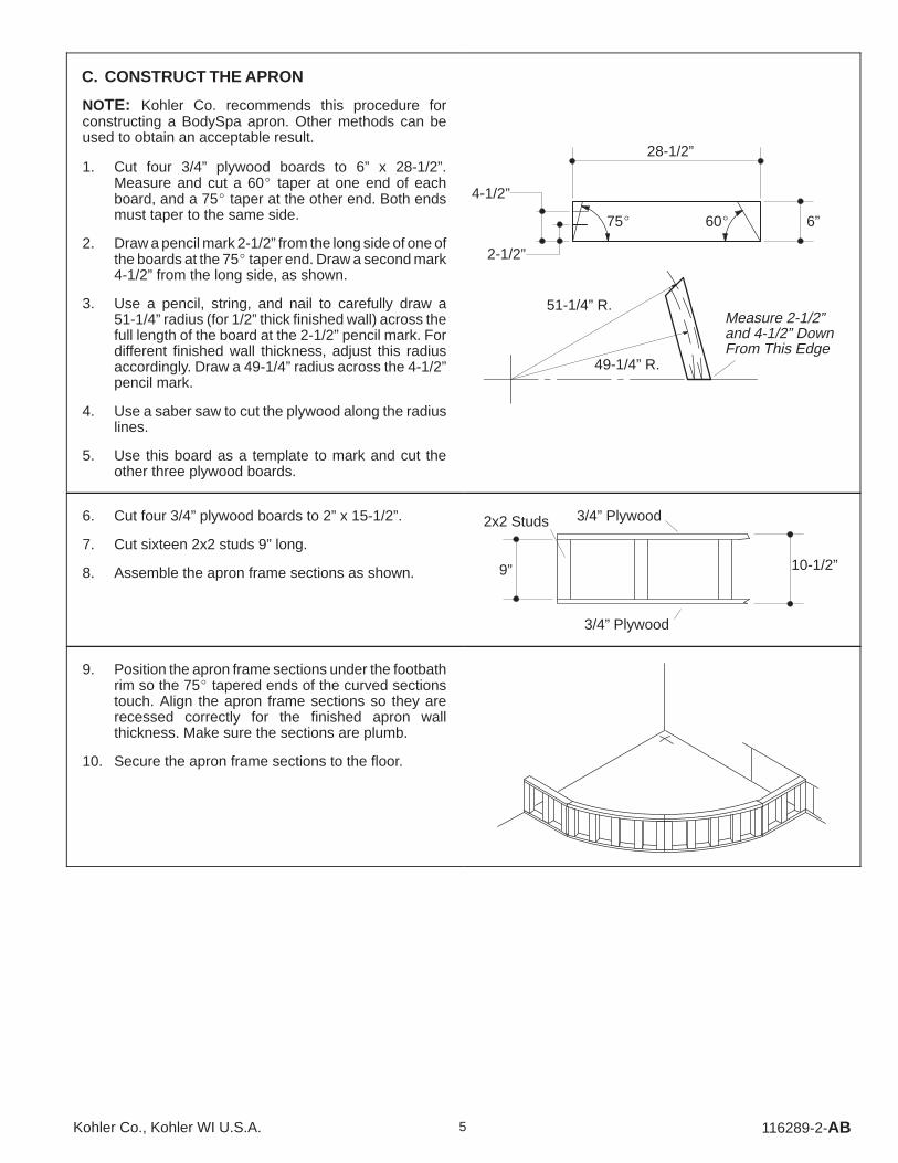
C. CONSTRUCT THE APRON
NOTE: Kohler Co. recommends this procedure forconstructing a BodySpa apron. Other methods can beused to obtain an acceptable result.
1. Cut four 3/4” plywood boards to 6” x 28-1/2”.Measure and cut a 60� taper at one end of eachboard, and a 75� taper at the other end. Both endsmust taper to the same side.
2. Draw a pencil mark 2-1/2” from the long side of one ofthe boards at the 75� taper end. Draw a second mark4-1/2” from the long side, as shown.
3. Use a pencil, string, and nail to carefully draw a51-1/4” radius (for 1/2” thick finished wall) across thefull length of the board at the 2-1/2” pencil mark. Fordifferent finished wall thickness, adjust this radiusaccordingly. Draw a 49-1/4” radius across the 4-1/2”pencil mark.
4. Use a saber saw to cut the plywood along the radiuslines.
5. Use this board as a template to mark and cut theother three plywood boards.
28-1/2”
6”75� 60�
2-1/2”
4-1/2”
51-1/4” R.
49-1/4” R.
Measure 2-1/2”and 4-1/2” DownFrom This Edge
6. Cut four 3/4” plywood boards to 2” x 15-1/2”.
7. Cut sixteen 2x2 studs 9” long.
8. Assemble the apron frame sections as shown. 9”
3/4” Plywood
3/4” Plywood
2x2 Studs
10-1/2”
9. Position the apron frame sections under the footbathrim so the 75� tapered ends of the curved sectionstouch. Align the apron frame sections so they arerecessed correctly for the finished apron wallthickness. Make sure the sections are plumb.
10. Secure the apron frame sections to the floor.
116289-2-AB 6 Kohler Co., Kohler WI U.S.A.
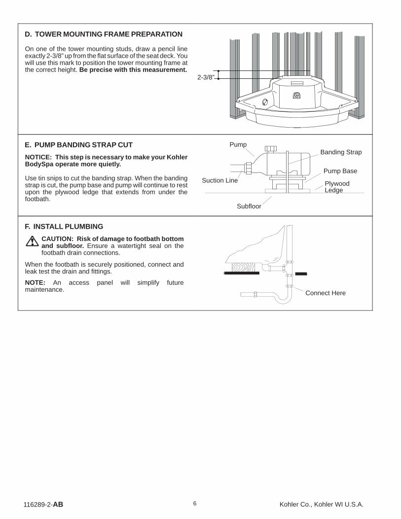
D. TOWER MOUNTING FRAME PREPARATION
On one of the tower mounting studs, draw a pencil lineexactly 2-3/8” up from the flat surface of the seat deck. Youwill use this mark to position the tower mounting frame atthe correct height. Be precise with this measurement.
2-3/8”
E. PUMP BANDING STRAP CUT
NOTICE: This step is necessary to make your KohlerBodySpa operate more quietly.
Use tin snips to cut the banding strap. When the bandingstrap is cut, the pump base and pump will continue to restupon the plywood ledge that extends from under thefootbath.
Suction Line
Pump
Subfloor
Banding Strap
Pump Base
PlywoodLedge
F. INSTALL PLUMBING
CAUTION: Risk of damage to footbath bottomand subfloor. Ensure a watertight seal on thefootbath drain connections.
When the footbath is securely positioned, connect andleak test the drain and fittings.
NOTE: An access panel will simplify futuremaintenance. Connect Here

116289-2-AB7Kohler Co., Kohler WI U.S.A.
6. BEFORE INSTALLING TOWER
A. INSTALL THE MOUNTING FRAME
Remove three 3/8” tower bolts from the locations shown,and carefully lift the tower out of the mounting frame.Carefully set the tower aside where it will not be damaged.
Bolts
Bolt
Set the mounting frame between the tower mountingstuds, and line up the bottom metal edge with the pencilline you drew on one of the studs.
Secure the mounting frame to the tower mounting studswith ten stainless steel drywall screws provided.
Pencil Line
Mounting Studs
MountingFrame
StainlessSteel DrywallScrew
116289-2-AB 8 Kohler Co., Kohler WI U.S.A.
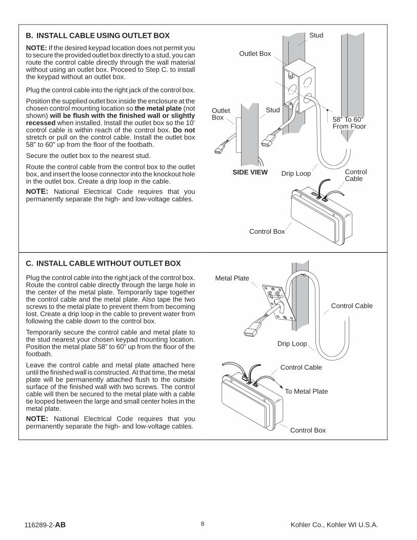
B. INSTALL CABLE USING OUTLET BOX
NOTE: If the desired keypad location does not permit youto secure the provided outlet box directly to a stud, you canroute the control cable directly through the wall materialwithout using an outlet box. Proceed to Step C. to installthe keypad without an outlet box.
Plug the control cable into the right jack of the control box.
Position the supplied outlet box inside the enclosure at thechosen control mounting location so the metal plate (notshown) will be flush with the finished wall or slightlyrecessed when installed. Install the outlet box so the 10’control cable is within reach of the control box. Do notstretch or pull on the control cable. Install the outlet box58” to 60” up from the floor of the footbath.
Secure the outlet box to the nearest stud.
Route the control cable from the control box to the outletbox, and insert the loose connector into the knockout holein the outlet box. Create a drip loop in the cable.
NOTE: National Electrical Code requires that youpermanently separate the high- and low-voltage cables.
Stud
Outlet Box
SIDE VIEW
StudOutletBox
ControlCable
Control Box
58” To 60”From Floor
Drip Loop
C. INSTALL CABLE WITHOUT OUTLET BOX
Plug the control cable into the right jack of the control box.Route the control cable directly through the large hole inthe center of the metal plate. Temporarily tape togetherthe control cable and the metal plate. Also tape the twoscrews to the metal plate to prevent them from becominglost. Create a drip loop in the cable to prevent water fromfollowing the cable down to the control box.
Temporarily secure the control cable and metal plate tothe stud nearest your chosen keypad mounting location.Position the metal plate 58” to 60” up from the floor of thefootbath.
Leave the control cable and metal plate attached hereuntil the finished wall is constructed. At that time, the metalplate will be permanently attached flush to the outsidesurface of the finished wall with two screws. The controlcable will then be secured to the metal plate with a cabletie looped between the large and small center holes in themetal plate.
NOTE: National Electrical Code requires that youpermanently separate the high- and low-voltage cables.
Control Cable
Control Box
To Metal Plate
Metal Plate
Control Cable
Drip Loop

116289-2-AB9Kohler Co., Kohler WI U.S.A.
D. CONNECT VARIABLE FLOW VALVEASSEMBLY TO PUMP
Loosen the variable flow valve assembly by unthreadingthe union nut. Reposition the variable flow valve assemblyso the outlet union lines up with the mounting frame unionnut. Securely handtighten the union nut. Be sure the unionO-ring is in place. Do not apply sealant to the union.
Handtighten the mounting frame union nut to the variableflow valve union. Be sure the union O-ring is in place. Donot apply sealant to the union.
Pump
MountingFrameUnion Nut
MountingFrame
Variable FlowValve Assembly
BACK VIEW
7. ELECTRICAL CONNECTIONS
WARNING: Risk of electrical shock. To reduce therisk of electric shock, connect only to a properlygrounded, grounding-type receptacle, protectedby a Ground-Fault Circuit-Interrupter (GFCI). Donot remove the plug’s grounding pin. Do not use agrounding adapter.
The Kohler BodySpa is equipped with a cord and plug.All wiring of the pump and control has been completedat the factory. A licensed electrician must install aGFCI-protected, 120 V, 20 A, grounded outlet. TheBodySpa may then be plugged into this outlet. No otherload should be on this circuit. Locate the outlet behindthe BodySpa, and within 24” of the pump.
* For bonding in accordance with national and localcodes.
Bonding(Earthing)Lug*
Pump
Plug-inCord
20 AReceptacle
Control Box
8. INSPECT CONNECTIONS
Check all electrical connections.
Open the hot and cold water valves, and check all supplyconnections for leaks. Fill the footbath to the overflow,and check the overflow and drain connections for leaks.

116289-2-AB 10 Kohler Co., Kohler WI U.S.A.
9. DOOR ENCLOSURE PREPARATION
The BodySpa door enclosure is designed to fit only theBodySpa footbath. Proper door enclosure assemblydepends upon installation of the footbath against squareand plumb studding. The stud supports must be within3/8” of plumb.
IMPORTANT: Leave studs exposed. The doorenclosure wall jambs must be secured directly to thedouble stud wall frame to achieve proper support of thedoor enclosure. Expanding wall anchors in a hollow wallwill not provide adequate support for the door enclosureassembly. Under no circumstances install the finishedwall material until instructed.
NOTE: The door enclosure components are identifiedwith removable labels. Refer to these labels to correctlyidentify and install the enclosure components.
10. INSTALL THE ENCLOSURE
A. INSTALL THE WALL JAMBS
Remove the wall jamb kit from the carton, and remove thewall jambs. Leave the wall jamb protective tape in place.Do not remove any other components from the carton atthis time.
Install one of the wall jambs by positioning it over thefootbath locating pin. The wall jamb’s two countersunkholes must be on the inside top. The wall jambs are notinterchangeable.
Use a level, and adjust the wall jamb to be exactly plumb.Secure the wall jamb to the double stud framing andfurring strips with four 2” stainless steel flathead screws(provided).
Repeat for the other wall jamb.
WallJamb
FootbathLocatingPin
CountersunkHoles
Level
2” StainlessSteel FlatheadScrew

116289-2-AB11Kohler Co., Kohler WI U.S.A.
CAUTION: Risk of concealed leakage. Theapplication of silicone sealant as instructed isessential to ensure a correct, watertight installation.Follow all sealing instructions exactly .
Apply a continuous bead of silicone sealant to the insideof the wall jamb where it contacts the footbath, as shown.
Repeat for the other wall jamb.
SiliconeSealant
TOP VIEWINSIDE OF
WALL JAMB
IMPORTANT! You have now completed the initial roughing-in phase of theBodySpa installation. Keep these instructions with the door enclosure so theyare readily available following the completion of finished wall construction.
116289-2-AB 12 Kohler Co., Kohler WI U.S.A.
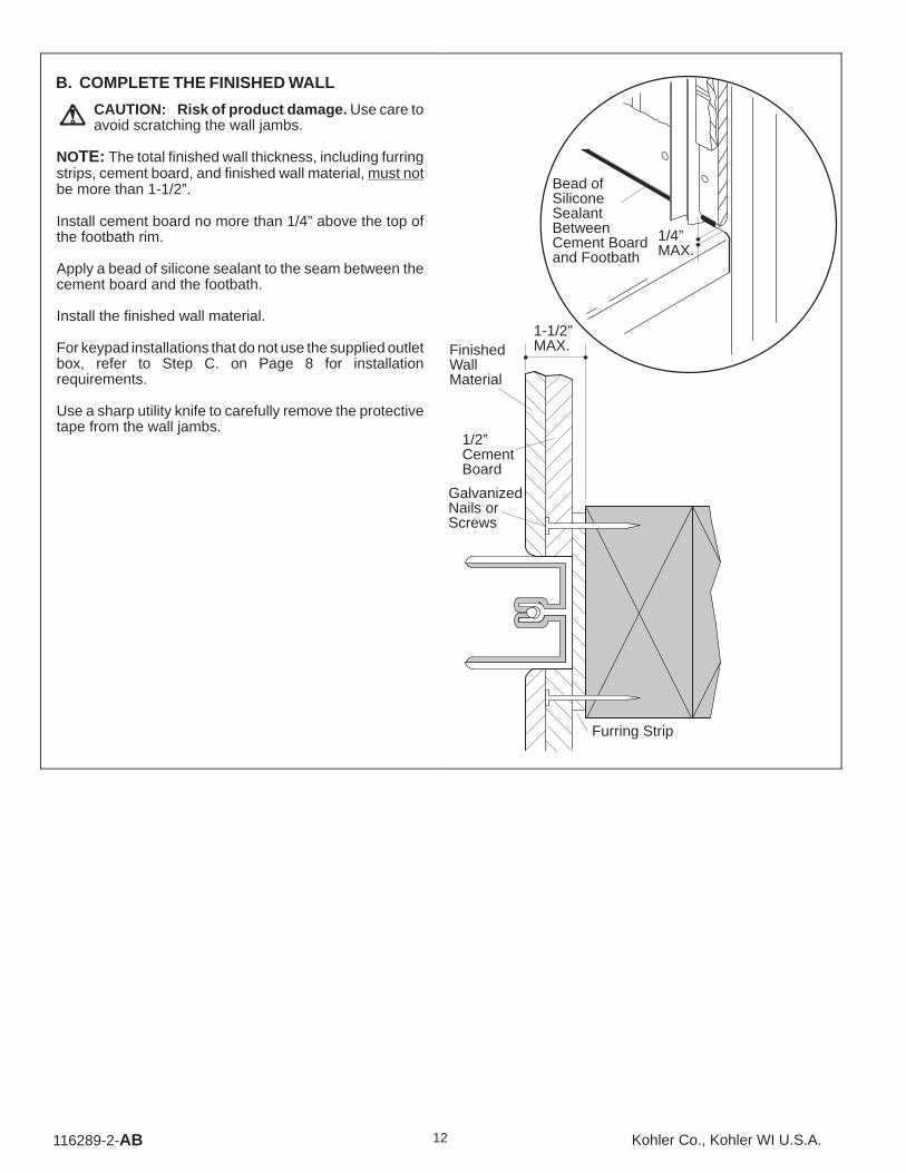
B. COMPLETE THE FINISHED WALL
CAUTION: Risk of product damage. Use care toavoid scratching the wall jambs.
NOTE: The total finished wall thickness, including furringstrips, cement board, and finished wall material, must notbe more than 1-1/2”.
Install cement board no more than 1/4” above the top ofthe footbath rim.
Apply a bead of silicone sealant to the seam between thecement board and the footbath.
Install the finished wall material.
For keypad installations that do not use the supplied outletbox, refer to Step C. on Page 8 for installationrequirements.
Use a sharp utility knife to carefully remove the protectivetape from the wall jambs.
1/2”CementBoard
GalvanizedNails orScrews
FinishedWallMaterial
1-1/2”MAX.
Furring Strip
1/4”MAX.
Bead ofSiliconeSealantBetweenCement Boardand Footbath

116289-2-AB13Kohler Co., Kohler WI U.S.A.
C. INSTALL THE SIDE PANELS
NOTE: The locating pins have been factory installed tohelp position the side panels and center supports. Do notremove, reposition, or modify the locating pins. Alteringthe locating pins will modify the fit and reduce the sealingability of the door panels, and may void warranty coverageof this product.
Slide one of the side panels into the wall jamb so the largerhorizontal frame is on top. The side panels are notinterchangeable. Insert the side panel fully into the walljamb, then raise and pivot the side panel so the centerpocket fits against the locating pin, as shown.
Attach a center support to the center frame of the sidepanel assembly. Connect the edge of the center supportto the side panel, and pivot the center support until it restsinside the side panel. Secure with eight #8 x 3/8” panheadscrews. Do not overtighten.
Repeat for the other side panel. Wall JambSidePanel
CenterSupport
FootbathLocating Pin
#8 x 3/8” PanheadScrews
CenterSupport Locating Pin
Side Panel
TOP VIEW
D. INSTALL THE HEADER
With assistance, lift the header between the centersupports so the bottom dimpled holes in the headerbrackets fit over the adjustment screws. Check thealignment of the side holes in both header brackets to theadjustment screw heads. If the holes do not line up withthe adjustment screw heads, loosen the headerbracket(s) setscrews, and realign the header bracket(s)until the holes line up with the adjustment screw heads.Retighten the header bracket setscrews.
Add a 1/4” flat washer to each of the two buttonheadscrews. Thread a buttonhead screw and washer througheach header bracket top hole, and into the center support.Securely tighten each buttonhead screw with thesupplied hex socket tool and a ratchet wrench.
Header
Center SupportHeaderBracket
1/4-20 x 5/8”ButtonheadScrew
1/4” Washer
Setscrew
AdjustmentScrew

116289-2-AB 14 Kohler Co., Kohler WI U.S.A.
E. SECURE THE SIDE PANELS
Ensure that each side panel is resting flat against thefootbath curb.
Plumb one side panel, and hold it firmly in place so itcannot shift. Use the countersunk holes at the top of thewall jamb as a guide, and drill 1/8” holes through the sidepanel wall frame. Only drill through the inside wall of theside panel wall frame. Secure the side panel with two #8x 5/8” flathead screws. Do not overtighten. Repeat for theother side panel. #8 x 5/8” Flathead
Screws
Wall JambHoles
Side Panel
FootbathCurb
F. SET THE HEADER HEIGHT
Measure the header height from the footbath rim at theend, and again in the center, as shown. Compare thedistance. The header should be 1/4” higher at the center.The combined weight of the door panels will pull theheader down until it is level or close to level.
Adjust the level of the header by first loosening thebuttonhead screw securing the header to the centersupport. Now back out the adjustment screw one or twoturns. Retighten the buttonhead screw with the hex sockettool and ratchet. This will cause the header to pivot slightlyupward.
Alternate this procedure on both ends of the header, andagain measure the header height at the end and thecenter. Repeat until the header is 1/4” higher at the center.Be sure to securely tighten the buttonhead screws withthe hex socket tool and ratchet when the adjustments arecomplete.
Very Important! The header must be 1/4” higher at thecenter before proceeding. The center of the header mustnot sag downward or the door panels will not operatecorrectly.
Header
Buttonhead Screw
Adjustment Screw
Side Panel SectionCenter Section
TapeMeasure

116289-2-AB15Kohler Co., Kohler WI U.S.A.
G. HANG THE SIDE DOOR PANELS
Fit a bushing over each outside track roller in the header.
With assistance, lift one of the side doors into place, andfit an outside track roller into each of the two holes in theglass.
Insert another bushing into each hole from the oppositeside of the glass. Thread a roller nut into each roller.Carefully handtighten each roller nut. Do not tighten witha wrench at this time, and do not try to level the door yet.
Repeat for the other side door.
Bushing
Header
Roller
Roller NutBushing
Side DoorPanel
H. HANG THE CENTER DOOR PANEL
Fit a bushing over each inside track roller in the header.
With assistance, lift the center door panel into place, andfit an inside track roller into each of the two holes in theglass.
Insert another bushing into each hole from the oppositeside of the glass. Thread a roller nut into each roller.Carefully handtighten each roller nut. Do not tighten witha wrench at this time, and do not try to level the doorpanels yet.
Bushing
Header
Roller
Roller Nut
Bushing
Center DoorPanel

116289-2-AB 16 Kohler Co., Kohler WI U.S.A.
I. ADJUST HEADER HEIGHT
Slide all three door panels to the center, and measure andrecord the distance from the footbath curb to the headerat three locations:
the left corner, along the wall jamb;
the right corner, along the wall jamb;
the center, along the center door panel.
If the three measurements are the same, no headeradjustment is required. Occasionally, the center heightmeasurement will be different from the corner measure-ments. In these cases, adjust the header in this manner:
Loosen one of the buttonhead screws about two completeturns. Next loosen the corresponding adjustment screw acomplete turn or two, and retighten the buttonhead screw.Check the center height measurement. Repeat thisprocedure until half the needed height correction isobtained.
Repeat this adjustment procedure on the other end of theheader.
NOTE: Remember that the center height measurementmust be the same as the corner measurements when thedoors are in the center.
Header
Buttonhead Screw
Adjustment Screw
J. INSTALL THE CENTER JAMB ASSEMBLIES
Press a center jamb assembly against the center support.Secure with six #8 x 1” panhead screws. Do notovertighten.
Repeat for the other side.
Center Jamb
Header Bracket
#8 x 1” PanheadScrews
CenterSupport
CenterJamb
TOP VIEW
116289-2-AB17Kohler Co., Kohler WI U.S.A.
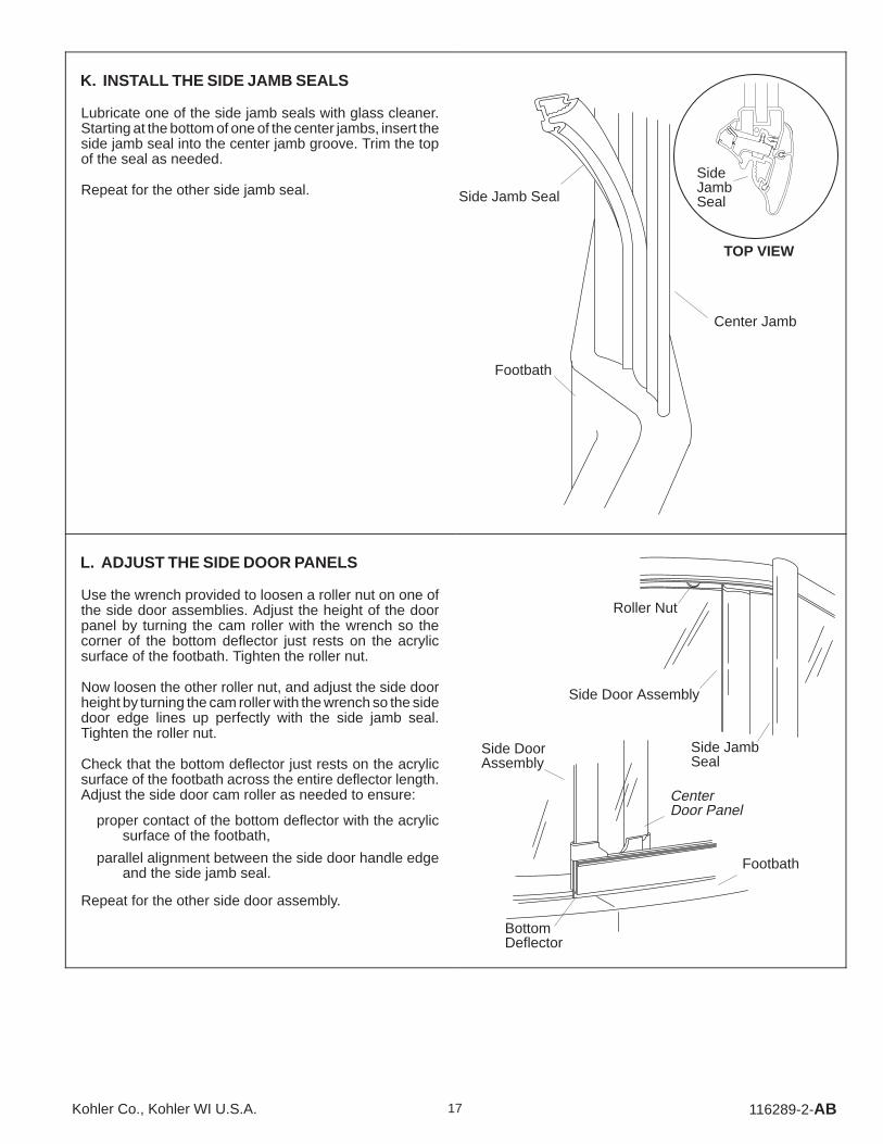
K. INSTALL THE SIDE JAMB SEALS
Lubricate one of the side jamb seals with glass cleaner.Starting at the bottom of one of the center jambs, insert theside jamb seal into the center jamb groove. Trim the topof the seal as needed.
Repeat for the other side jamb seal.
Center Jamb
Side Jamb Seal
Footbath
SideJambSeal
TOP VIEW
L. ADJUST THE SIDE DOOR PANELS
Use the wrench provided to loosen a roller nut on one ofthe side door assemblies. Adjust the height of the doorpanel by turning the cam roller with the wrench so thecorner of the bottom deflector just rests on the acrylicsurface of the footbath. Tighten the roller nut.
Now loosen the other roller nut, and adjust the side doorheight by turning the cam roller with the wrench so the sidedoor edge lines up perfectly with the side jamb seal.Tighten the roller nut.
Check that the bottom deflector just rests on the acrylicsurface of the footbath across the entire deflector length.Adjust the side door cam roller as needed to ensure:
proper contact of the bottom deflector with the acrylicsurface of the footbath,
parallel alignment between the side door handle edgeand the side jamb seal.
Repeat for the other side door assembly.
Roller Nut
Side Door Assembly
BottomDeflector
Footbath
Side JambSeal
CenterDoor Panel
Side DoorAssembly

116289-2-AB 18 Kohler Co., Kohler WI U.S.A.
M. ADJUST THE CENTER DOOR PANEL
Check if the center door panel hangs parallel with bothside door assemblies. Also check that the bottomdeflector just makes contact with the acrylic surface of thefootbath.
Loosen one or both roller nuts, and adjust the center doorpanel by turning the cam roller with the wrench to obtainproper fit. Tighten any loose roller nuts.
Center Door Panel
Bottom Deflector
N. INSTALL THE BACKSTOP
Choose a backstop and cover to match the color of thedoor frame.
Insert the well nut into the pre-drilled hole in the center ofthe footbath curb.
Attach the backstop to the footbath curb by securelythreading a #10 x 1” panhead screw into the well nut. Donot overtighten.
Apply silicone sealant to the backstop cap, then press itonto the backstop.
Well Nut
Backstop
Curb
BackstopCap
#10 x 1” Panhead Screw
ApplySealant
O. INSTALL THE DOOR HANDLES
Fit the gasket over the groove in the side of the door panel.Loosen the six handle clamp screws. Press the handleover the gasket so the clamp and screws are on the inside.Thread in one or two screws to temporarily hold thehandle in place. Note that the handle protrusion fits intothe groove in the glass panel. Slide the handle up or downso the bumper flat rests on the footbath curb. Carefullytighten all six screws. Use care to avoid stripping thescrews.
Repeat this procedure for the other handle.
HandleClamp
Gasket
Handle
Side Door Panel
HandleClampScrews
BumperFlat

116289-2-AB19Kohler Co., Kohler WI U.S.A.
P. ADJUST THE STOP BLOCKS
NOTE: This step is critical to prevent the side door panelsfrom accidentally slamming against one another.
With the doors all closed, open the left side door. Slide theloose stop block up against the exposed center door roller.
Close the left side door so it rests against the side jambseal. Slowly open the right side door until it nearly touchesthe left side door. A 1/4” gap between the side door paneledges is sufficient.
Open the left side door to expose the stop block. Carefullysecure the stop block in place by tightening the stop blocksetscrew.
Repeat this procedure for the other stop block.
InsideTrack
Stop BlockSetscrew
Header
Roller
Center DoorPanel
Stop Block
Q. APPLY SEALANT
Door seals are an integral part of this door. However,sealing with a quality clear silicone sealant is necessaryto ensure a properly functioning, watertight unit.
The required sealing procedure follows:
Mask both edges of joint to be sealed, maintaining ajoint width of 1/8” to 3/16”.
Apply a uniform bead of sealant. Smooth the bead withyour finger.
Remove the tape from the sealed joints immediatelyafter smoothing the bead.
Repeat for all areas to be sealed.
Very Important! Apply silicone sealant to the outsidebottom edge of the center jambs, side panels, and walljambs only. On the inside, apply a bead of silicone sealantvertically along the seam between the wall jambs andfinished wall surface. Do not apply sealant to the inside ofthe side panels.
FootbathSeal Locations
Masking Tape
Seal
INSIDE UNIT
1/8” to 3/16”
IMPORTANT! You have now completed the door enclosure installation phaseof the BodySpa installation. Keep these instructions with the tower so they arereadily available for the final installation procedures.
116289-2-AB 20 Kohler Co., Kohler WI U.S.A.
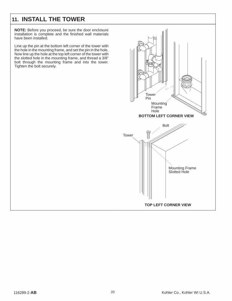
11. INSTALL THE TOWER
NOTE: Before you proceed, be sure the door enclosureinstallation is complete and the finished wall materialshave been installed.
Line up the pin at the bottom left corner of the tower withthe hole in the mounting frame, and set the pin in the hole.Now line up the hole at the top left corner of the tower withthe slotted hole in the mounting frame, and thread a 3/8”bolt through the mounting frame and into the tower.Tighten the bolt securely.
TowerPin
MountingFrameHole
BOTTOM LEFT CORNER VIEW
Mounting FrameSlotted Hole
Bolt
Tower
TOP LEFT CORNER VIEW

116289-2-AB21Kohler Co., Kohler WI U.S.A.
Route the tower cable into the large hole in the back of themounting frame. Snap the modular plug on the end of thetower cable into the left jack of the control box. Install thelarge strain relief bushing over the tower cable, and insertit into the large mounting frame hole.
NOTE: National Electrical Code requires that youpermanently separate the high- and low-voltage cables.
Tower Cable
Control Box
Mounting Frame
LargeStrainRelief
Route the waterfall light wires through the small hole in theback of the mounting frame. With the pump access panelremoved, connect the waterfall light wire connectors tothe transformer terminals – white to white; black to black.Install the small strain relief bushing over the waterfall lightwires, and insert it into the small mounting frame hole.
Mounting Frame
FromWaterfallLight
SmallHole
SmallStrainReliefBushing
To Control BoxSnap
Transformer

116289-2-AB 22 Kohler Co., Kohler WI U.S.A.
Securely handtighten the tower union nut to the mountingframe union. Be sure the union O-ring is in place.
TowerUnionNut
MountingFrameUnion
Carefully pivot the tower closed. Line up the holes at thetop and bottom right corners of the tower with the slottedholes in the mounting frame. Thread a 3/8” bolt throughthe mounting frame and into the tower at the top andbottom. Tighten the bolts securely, but do not overtighten.
Water testing and inspection is required later. You maywant to only install and handtighten one of the requiredbolts at this time. Both bolts will need to be securelytightened later.
Bolt
Bolt
12. COMPLETE INSTALLATION
A. INSTALL HANDLES AND SPOUT
CAUTION: Risk of property damage. The valve,spout, and other plumbing fittings must beadequately sealed to prevent water leakagebehind the finished wall.
Install the faucet handles and spout according to themanufacturer’s instructions. Seal around the plumbingfittings.

116289-2-AB23Kohler Co., Kohler WI U.S.A.
B. INSTALL KEYPAD
CAUTION: Risk of personal injury or productdamage. The metal plate must be installed flushwith the finished wall or slightly recessed (maximum1/4”).
Feed the control cable through the hole in the metal plate.Use two flathead screws to attach the metal plate to theoutlet box or finished wall material so the metal plate isflush with the finished wall or slightly recessed(maximum 1/4”).
Snap the keypad modular plug into the keypad cable jack.
Apply silicone sealant to each of the keypad screw holes,and secure the keypad to the metal plate with fourpanhead screws.
FinishedWall
FlatheadScrew
MetalPlate
Keypad
PanheadScrew
Snap Plugs
Apply SiliconeSealant
CAUTION: Risk of personal injury or productdamage. Prevent water damage to the keypad byapplying silicone sealant as instructed.
IMPORTANT: Apply a continuous bead of clear siliconesealant to the cover plate sealant grooves, as shown.
Slip the center pin at the top of the cover plate up throughthe hole in the keypad. Secure the cover plate to thekeypad with a panhead screw.
Select the bottom cap – it contains the word “KOHLER”,and has a small notched area along the contact surfaceedge.
IMPORTANT: Apply silicone sealant to the bottom capalong the back surface and also to the edge that contactsthe cover plate. Align the bottom cap holes with the coverplate pins, and push the cap into place. Repeat for the topcap.
Remove any excess sealant.
CenterPin
Cover Plate
Keypad
PanheadScrew
Apply SiliconeSealant toSealantGrooves
BottomCap
Apply SiliconeSealant
Apply SiliconeSealant
TopCap
116289-2-AB 24 Kohler Co., Kohler WI U.S.A.
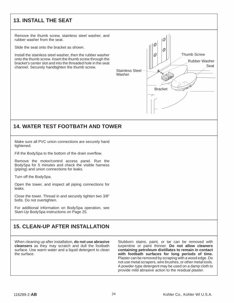
13. INSTALL THE SEAT
Remove the thumb screw, stainless steel washer, andrubber washer from the seat.
Slide the seat onto the bracket as shown.
Install the stainless steel washer, then the rubber washeronto the thumb screw. Insert the thumb screw through thebracket’s center slot and into the threaded hole in the seatchannel. Securely handtighten the thumb screw. Seat
Thumb Screw
Stainless SteelWasher
Rubber Washer
Bracket
14. WATER TEST FOOTBATH AND TOWER
Make sure all PVC union connections are securely handtightened.
Fill the BodySpa to the bottom of the drain overflow.
Remove the motor/control access panel. Run theBodySpa for 5 minutes and check the visible harness(piping) and union connections for leaks.
Turn off the BodySpa.
Open the tower, and inspect all piping connections forleaks.
Close the tower. Thread in and securely tighten two 3/8”bolts. Do not overtighten.
For additional information on BodySpa operation, seeStart-Up BodySpa instructions on Page 25.
15. CLEAN-UP AFTER INSTALLATION
When cleaning up after installation, do not use abrasivecleansers as they may scratch and dull the footbathsurface. Use warm water and a liquid detergent to cleanthe surface.
Stubborn stains, paint, or tar can be removed withturpentine or paint thinner. Do not allow cleanerscontaining petroleum distillates to remain in contactwith footbath surfaces for long periods of time.Plaster can be removed by scraping with a wood edge. Donot use metal scrapers, wire brushes, or other metal tools.A powder-type detergent may be used on a damp cloth toprovide mild abrasive action to the residual plaster.

116289-2-AB25Kohler Co., Kohler WI U.S.A.
16. CONFIRM PROPER OPERATION
A. START-UP BODYSPA
Please perform the following so the owner can safelyreceive the benefits of their BodySpa.
Water temperature in the footbath should not exceed104�F (40�C).
1. Fill the footbath to the bottom of the drain overflow.
NOTE: Refer to the chart at right for the proper operatingsequence.
2. Turn on the BodySpa by pressing the Power buttonon the keypad. Water will flow from the Waterfall atthe lowest flow setting, and the Waterfall light will turnon. The light will remain on throughout the operatingsequence.
3. Use the ↑ and ↓ arrows to vary the water force.
4. Press the Body Jet button. Water will flow from BodyJet arrays 2, 3, and 4 at low speed. Water will stopflowing from the Waterfall.
5. This BodySpa features five pairs of Body Jets. Pressany combination of buttons 1 through 5 to choose thedesired water distribution.
6. Use the ↑ and ↓ arrows to vary the water force.
7. A built-in timer automatically stops the motor after 20minutes of operation.
TO METHOD OBSERVE
Turn on theBodySpa.
Select desiredBodySpafeatures.
Increase waterforce, press the ↑button.
Decrease waterforce, press the ↓button.
Shut off theBodySpa.
RestartBodySpaafter the20 minutecycle iscomplete.

116289-2-AB 26 Kohler Co., Kohler WI U.S.A.
B. TROUBLESHOOTING
Here’s what you need to do if you require service: First review the installation instructions to ensure correct installation.If you are unable to correct the problem, call our Customer Service Department for direct help. Dial 1-800-4-KOHLER.
SYMPTOMS PROBABLE CAUSES CORRECTIVE ACTION
1. BodySpa doesnot start/stop.
A. No power to pump/control. A. Set/Reset GFCI breaker; check wiring topump/receptacle.
B. Harness is blocked. B. Remove blockage.
C. Keypad disconnected from pump/controlbox.
C. Reconnect keypad.
D. Faulty keypad. D. Replace keypad.
E. Faulty circuit board. E. Replace circuit board inside control box.
F. Faulty motor/pump assembly. F. Replace motor/pump assembly.
G. Not enough water in footbath. G. Fill footbath to drain overflow.
2. Water flowsurges
A. Not enough water in footbath. A. Fill footbath to drain overflow.surges.
B. Suction blocked. B. Remove obstruction.
C. Harness is blocked. C. Remove blockage.
3. Motor starts, allBody Jets are
A. Jet is blocked. A. Remove blockage.Body Jets arenot functioning. B. Faulty keypad. B. Replace keypad.not functioning.
C. Butterfly valve wiring loose or damaged,or butterfly valve is faulty.
C. Identify source of fault and correct, orreplace faulty butterfly valve.
4. Motor starts,waterfall does
A. Waterfall is blocked. A. Remove blockage.waterfall doesnot function. B. Faulty keypad. B. Replace keypad.not function.
C. Butterfly valve wiring loose/damaged –butterfly valve is faulty.
C. Identify source of fault and correct, orreplace faulty butterfly valve.
5. Water increaseswhen ↓ keypadbutton ispressed –decreases when↑ button ispressed.
A. Variable flow valve wiring error. A. Reverse variable flow valve wireconnections.
6. Waterfall lightdoes not work
A. Light bulb is burned out. A. Replace light bulb.does not work.
B. Loose or damaged wiring. B. Identify source of fault and correct.
7. BodySpa stopsautomatically
A. GFCI trips. A. Identify source of fault and correct.automaticallybefore 18minutes.
B. Motor overheated and protection deviceactivated.
B. Check for blockage at motor vents.Remove blockage and allow motor tocool.Check for suction/harness blockage.Remove blockage and allow motor tocool.
8. BodySpa doesnotautomatically
A. Faulty timer mechanism. A. Replace timer board inside pump/motor.
automaticallystop after 22minutes.
B. Wiring error. B. Refer to dealer.
9. Noisy operation. A. Pump strap has not been cut. A. Cut strap with tin snips.
B. Not enough water in footbath. B. Fill footbath to drain overflow.

116289-2-AB27Kohler Co., Kohler WI U.S.A.

�
116289-2-AB 28 Kohler Co., Kohler WI U.S.A.