BODY ELECTRICAL EQUIPMENT - Zuki Offroad · 21-2. HEAD LIGHT. WIRING CIRCUIT. Headlight Headlight I...
22
21-1. COMBINATION METER .................................. 21-2. HEAD LIGHT .......................................... 21-3. TURN SIGNAL LIGHT AND HAZARD WARNING LIGHT ....... 21-4. WINDSHIELD WIPER MOTOR ............................. 21-5. WATER TEMPERATURE METER AND GAUGE ............... 21-6. FUEL LEVEL METER AND GAUGE ........................ 21-7. BRAKE WARNING LAMP ............................... 21-8. OIL PRESSURE LAMP .................................. 4 WHEEL DRIVE LAMP ................................. 21-10. SEAT BELT WARNING LAMP/BUZZER ..................... ................... . ..~I-I ..... 21-14. ............................................. 21-15. WIRING HARNESS ROUTING ............................ 21-16. WIRING DIAGRAM .................................... SECTION 21 BODY ELECTRICAL EQUIPMENT CONTENTS 21-9. 21-11. MAIN SWITCH KEY WARNING BUZZER 21-12. ILUMINATION CONTROLLER.............................................. 21-13. REAR DEFOGGER ( hard-top ) ...................................... FUSE BOX 21-2 21-4 21-7 21-9 21-11 21-12 21-13 21-14 21-15 21-15 21-16 21-16 21-16 21-18 21-19 21-22 21-1
Transcript of BODY ELECTRICAL EQUIPMENT - Zuki Offroad · 21-2. HEAD LIGHT. WIRING CIRCUIT. Headlight Headlight I...

21-1. COMBINATION METER . . . . . . . . . . . . . . . . . . . . . . . . . . . . . . . . . .
21-2. HEAD LIGHT . . . . . . . . . . . . . . . . . . . . . . . . . . . . . . . . . . . . . . . . . .
21-3. TURN SIGNAL LIGHT AND HAZARD WARNING LIGHT. . . . . . .
21-4. WINDSHIELD WIPER MOTOR . . . . . . . . . . . . . . . . . . . . . . . . . . . . .
21-5. WATER TEMPERATURE METER AND GAUGE . . . . . . . . . . . . . . .
21-6. FUEL LEVEL METER AND GAUGE . . . . . . . . . . . . . . . . . . . . . . . .
21-7. BRAKE WARNING LAMP . . . . . . . . . . . . . . . . . . . . . . . . . . . . . . .
21-8. OIL PRESSURE LAMP . . . . . . . . . . . . . . . . . . . . . . . . . . . . . . . . . .
4 WHEEL DRIVE LAMP . . . . . . . . . . . . . . . . . . . . . . . . . . . . . . . . .
21-10. SEAT BELT WARNING LAMP/BUZZER . . . . . . . . . . . . . . . . . . . . .
. . . . . . . . . . . . . . . . . . .
. ..~I-I
. . . . .
21-14. . . . . . . . . . . . . . . . . . . . . . . . . . . . . . . . . . . . . . . . . . . . . .
21-15. WIRING HARNESS ROUTING . . . . . . . . . . . . . . . . . . . . . . . . . . . .
21-16. WIRING DIAGRAM . . . . . . . . . . . . . . . . . . . . . . . . . . . . . . . . . . . .
SECTION 21
BODY ELECTRICAL EQUIPMENT
CONTENTS
21-9.
21-11. MAIN SWITCH KEY WARNING BUZZER
21-12. ILUMINATION CONTROLLER..............................................
21-13. REAR DEFOGGER ( hard-top )......................................
FUSE BOX
21-2
21-4
21-7
21-9
21-11
21-12
21-13
21-14
21-15
21-15
21-16
21-16
21-16
21-18
21-19
21-22
21-1
James Oaks
Text Box
www.zukioffroad.com

21-2

Wire colorG/R . . . Green/Red Or . Orange0 . . . . . Black BI/B . B l u e / B l a c k0rlB . . . Brown/Black w . WhiteY/B . . . Yellow/Black Y / R . Y e l l o w / R e dB/W . . Black/White G/Y . . Green/YellowW/R . White/Red Y / W . . Y e l l o w / W h i t eRIB . Red/Black R / Y . R e d / Y e l l o wG . . . Green R/G . . . Red/Green
1.
2.3.4.5.
6.7.8.9.
10.
50,000 mile, 80,000 mile and 11. 4WD light100,000 mile sensor switch 12. Noise’suppressorTurn signal pilot light (Lb 13. Turn signal pilot light (RICancel switch 14. Beam pilot lightSeat belt warning light 15. Fuel level meterBrake oil level warning light 16. Temp. meterand parking brake light 17. Illumination lightCharge light” 18. TachometerEngine oil pressure light 19. Seat belt warning buzzer“CHECK ENGINE" light 20. Combination meterDiode 21. Check switchSeat belt relay
[Combination meter without tachometer] [Combination meter with tachometer]
4. TEMP. meter5. Meter print plate6. Bulb7. Socket
Combination meter
Fig. 21-18. Tachometer
REMOVAL AND INSTALLATION1. Disconnect battery negative cable.2. Remove instrument lower panel.3. Lower steering column.4. Remove combination meter cover.5. Disconnect speedometer cable and wire
harness coupler.
7. To install combination meter, reverse aboveremoval procedure.
6. Remove combination meter.
Fig. 21-2
2. Speedometer3. Fuel Meter
21-3
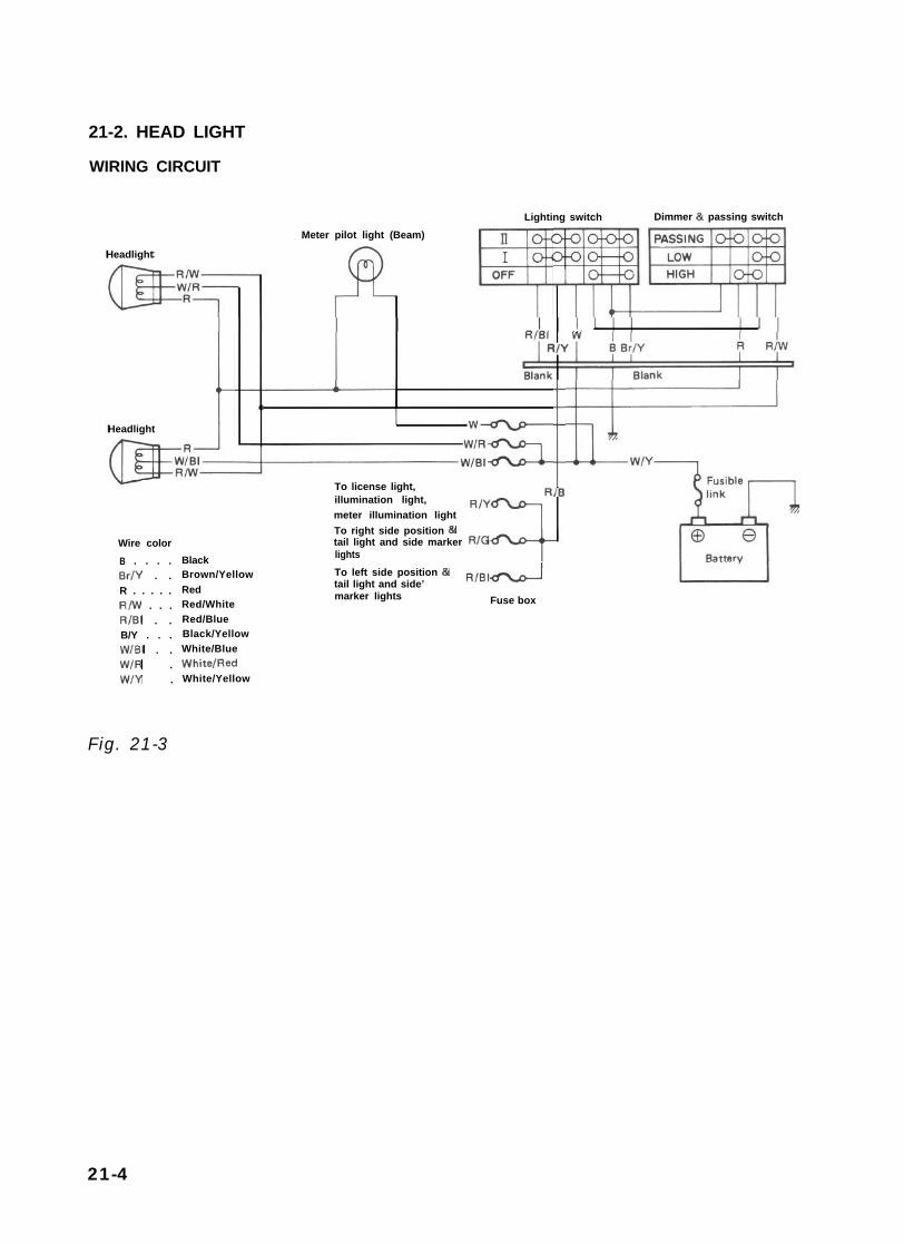
21-2. HEAD LIGHT
WIRING CIRCUIT
Headlight
Headlight I
Meter pilot light (Beam) III4
Lighting switch Dimmer & passing switch
To license light,illumination light,meter illumination light
Wire colorB . . . . BlackBr/Y . . Brown/YellowR . . . . . RedR/w . . . Red/WhiteRIBI . . Red/BlueB/Y . . . Black/YellowWIBI . . White/BlueW/R . WhitelRedW/Y . White/Yellow
To right side position &tail light and side marker RIGlights
iIB
To left side position 81tail light and side’ RIBIdmarker lights Fuse box
Fig. 21-3
21-4

HEADLIGHT INSPECTION1. Lighting (Low beam, High beam, Passing)2. Mounting3. Dirt and cracks on lenses4. Main beam axis direction and brightness
HEADLIGHT BEAM SETTING (STANDARD PROCEDURE)Before setting the headlight beams, adjust air pressures of four tires to a specified value respectively. Movethe vehicle up and down by hand to settle its attitude. Then move it over a flat surface. There are availablea variety of headlight beams setting methods (e.g., the screen method using a focusing tester, etc.). How-ever, the method described here does not use such tester.
Beam alignmentUnless otherwise obligated by the local regulations, align the headlight beams according to the followingprocedure. Place a blank wall 7.6 m (25 ft) ahead of the headlight. Check to see if the hot spot (highintensity zone) of each main (low) beam axis falls as illustrated below. The beam alignment should becarried out with one driver (68 kg, 150 lb) aboard.
7.6 m(25 ft). .
Fig. 21-4
LH. HE
X$ H
II
\D LIGHT RH. HEAD LIGHT
A B
X - X : Horizontal center line of headlights H : 25 mm (0.98 in.)A - A : Vertical center line of left headlightB - 6 : Vertical center line of right headllght
Fig. 21-521-5

MAINTENANCE(1) Headlight adjustment
There are two screws (1)and (2)which can beused for adjustment. Use these screws toadjust the headlight position for the verticaland horizontal alignment of each beam.
(2) Head light dimmer switchUsing circuit tester, check each circuit forcontinuity by putting tester probe pins tothe terminals shown in Fig. 21-7. With switchkept in LOW BEAM position, tester shouldindicate continuity between terminals 0 and@ . Similarly, there should be continuity
between terminals @ and @ when in HIGHBEAM position.
Fig. 21-6
Switch connector
1 ” m m m m - J1. Green/Red (Green/Black) 8. Red2. Green/Yellow 9. Blue/Green3. Green 10. Brown/Yellow4. Yellow 11. Red/Blue5. White/Blue 12. Red/Yellow6. Yellow/Blue 13. White7. Red/White
1 17 1 18 1 19 1
14. Yellow/White15. Blue16. Blue/Red
Fig. 21-7
17. Blue/Black18. Black19. Blue/White
Combination switch (Lighting switch circuit)
Fig. 27-8
I I I I I, Brown(Yellow
21-6

21-3. TURN SIGNAL LIGHT AND HAZARD WARNING LIGHT CIRCUIT DESCRIPTION
1 Right turn signal2.. Left turn signal3. Battery4. Main switch5. Fuse6. Turn signal and hazard warning switch7. Turn signal and hazard warning relay
Fig. 21-9
8. Green/Yellow9. White/Yellow
10. Yellow11. Yellow/Blue12. Green13. Black/Blue14. Green/Red
15. Meter pilot light (Right)16. Meter pilot light (Left)17. White/Green
When hazard warning switch is “OFF”, Yellow lead @ is connected to Yellow/Blue lead 0.When the hazard warning switch is “ON”, White/Green lead @I is connected to Yellow/Blue lead @I, andGreen lead (12)to both Green/Yellow lead @ and Green/Red lead @.When Turn-signal switch is “ON” for right turn, Green lead @ is connected to Green/Yellow lead @.When Turn-signal switch is “ON” for left turn, Green lead @ is connected to Green/Red lead @.
21-7

INSPECTION1) Trouble diagnosis
Symptom
1. Lights will not come on in either left orright group of light.
2. Hazard light comes on but turn signallights will not.
3. No light comes on; or lights light up butdo not flicker.
4. Turn signal lights are satisfactory, buthazard light will not come on.
5. Flickering freueqncy is erratic, or lightsremain lit.
6. Turning on hazard warning switch lights uponly one group of lights.
2) Turn signal switchUsing circuit tester, check for continuitybetween each pair of terminals by referring tothe chart given below and figure at the rightfor each position of turn signal switch lever.Discontinuity means that contact points areburnt or otherwise defective in the switch.For example, switch is in sound condition ifcontinuity is noted between terminals 2 and3, with lever in r ight-turn posit ion, andbetween terminals 1 and 3, with lever in left-turn position.
Possible cause
Fusible link is blown off.
Open circuit (due to poor point contact) in turnsignal dimmer switch.Defective relay unit.
Open circuit in hazard warning switch.
Light bulbs are defective or improperly grounded.
Defective contact in dimmer switch.
Switch connector
I ” ” ” yr m -
1. Green/Red (Green/Black) 8. Red2. Green/Yellow 9. Blue/Green3. Green 10. Brown/Yellow4. Yellow 11. Red/Blue5. White/Blue 12. Red/Yellow6. Yellow/Blue 13. White7. Red/White
Fig. 21-10
3) Hazard warning switchDisconnect, lead wire of the hazard warning switch at its coupler. Set switch to ON position and checkfor continuity with circuit tester between each of the following pairs of terminals; 2 and 3, 1 and 3, 5and 6 among those shown in Fig. 21-10. The switch is in sound condition if continuity is noted betweeneach pair.
Turn signal & hazard warning switch
1(Green/Red orGreen/Black)
(Grien) 2(Green/Yellow) (Yeiow)
5(YelloiIBlue) (White/Blue)
Hazard warning Left-N-Right 0 a- 0 0 0Left 0 0 l 0
Turn signal Neutral * 0Right l a * 0
21-8

21-4. WINDSHIELD WIPER MOTOR
CIRCUIT DESCRIPTIONThe circuit is designed so that, when the Wiper Switch is turned “OFF”, the blade will automatically returnto the horizontal position. In Fig. 21-11, when the Wiper Switch is turned “ON” while the Main Switch is“ON”, current is supplied to the Wiper Motor from the Battery, the motor rotates and the blade moves.The gear mechanism which converts rotational movement of the motor into swinging movement of theblade has a cam on the final gear shaft. The cam switches the contacts of P0 and P2 every revolution.(At the blade stop position, the contact is switched from P2 to P1.)
Repeated contact making and breaking is independent of the wiper motor rotation. When the Wiper Switchis turned “OFF” while the blade is in a position other than the rest position, motor current path is changed(i.e. BI/W + BI + MOTOR). Therefore, the motor keeps rotating even though the wiper switch is turned“OFF”, and the blade will return to the rest position.When the blade returns to the rest position, the cam contact is changed from P2 to P1 and motor currentis shunted. When supply to the motor is cut off, a counter electromotive force is generated in thearmature. As a result of this counter electromotive force, current flows through the motor and shuntcircuit and the motor stops and the wiper blade stays in the specified position.
[INTERVAL WIPER RELAY CIRCUIT (OPTIONAL)]When the wiper switch is set to the interval position with the ignition switch ON (the condenser is chargedat this time), current from the battery flows through the yellow/blue wire, generates magnetic force in thecoil in the relay and causes the switch in the relay to turn ON. Then current is transmitted in the sequenceof yellow/blue, relay, wiper switch and blue and causes the wiper motor to rotate (meanwhile, the conden-ser discharges). By the time the wiper motor makes one rotation and the cam in the motor comes to theautomatic stop position P1, the condenser in the relay has finished discharging (no magnetic force in thecoil in the relay). Then the switch in the relay turns OFF and the wiper stops. They remain that way untilthe condenser is fully charged. As soon as the condenser begins discharging after being fully charged,magnetic force generated in the coil in the relay causes the switch to turn ON. As described above, intervaloperation of the wiper motor is controlled by charging and discharging of the condenser.
2-speed type
OFF
1. Battery2. Main switch3. Fuse box4. Wiper motor5. Wiper switch6. Washer switch7. Washer motor
W/Y : White/YellowB/BI : Black/BlueY/El: Yellow/BlueBI/W: Blue/WhiteBI : Blue
LOW SPEEDBIIR : Blue/Red
HIGH SPEED
Fig. 21-11
6
21-9

3-speed type r __-- - ---- - ---- ~-*
Fig. 21-12
rI
-I
IIIMI > p1 p2
fil
II0PO I
- - m - - e - - - - J
OFF
IN1
LOW
MAINTENANCE1) Wiper trouble diagnosis
When wiper motor does not start even ifWiper Switch is turned “ON”, check leadconnections and coupler connections. Then,check the following.a) Fuse blown or mounted incorrectly.b) Wiper switch:
To check wiper switch: remove couplersand check continuity between followingterminals by using circuit tester.
Switch connector
14. Yellow/White15. Blue16. Blue/Red17. Blue/Black18. Black18. Blue/White
2-speed typeYellow/
white Blue Blue/red Blue/white
High speed 0 aLow speed 0 lOFF e l
Wiper switch 3-speed type
OFF
Interval
Yellowl Blue/white white Blue “lr”,“d/ rzay Black
1. Battery2. Main switch3. Fuse box4. Wiper motor5. Wiper & washer switch6. Washer motor
Wire colorB : BlackB/B1 : Black/BlueBI : BlueBIIR : Blue/RedBI/W: Blue/WhiteY/B1 : Yellow/Blue
2L+
A ‘U
c) Break in wiper motor armature or poorcommutator brush contact:To check these, check continuity betweenBlue lead and ground, and Blue/Red wireand ground respectively.
2) No-load run testAs shown in Fig. 21-13, using a 12V battery,connect positive battery terminal to Blueterminal and the negative terminal to motor.If motor rotates at 45 - 57 r/min, this isacceptable (for Lowspeed check). For High-speed check, connect the positive terminal toBlue/Red terminal and negative terminal tomotor. If motor rotates at 67 - 81 r/min,this is acceptable.
Fig. 21-13 Testing motor1. Positive terminal2. Negative terminal
Wiper switch21-10

3) Automatic stop action testConnect yellow terminal of motor to positive@ battery terminal, and put a jumper
between Blue/White (Blue/Black) and Blueterminals to see if motor output shaft comesto a halt at a certain, not just any, angularposition. That position corresponds to start-ing position of the blade. Using jumper,stop motor a number of times to make surethat motor stops at the same position eachtime.
Fig. 21-14 Testing motor1. Positive terminal
2. Negative terminal3. Put a jumper between
Blue/White (Blue/Black) and Blue
4) Internal wiper relay test1. Disconnect wiper & washer switch coupler.2. Turn wiper switch to “I NT” position.3. Connect positive battery terminal to
Yellow/White coupler terminal and nega-tive battery terminal to Black terminal.If an operating sound is heard, the relay isat work properly.
Switch connector
14. Yellow/White15. Blue16. Blue/Red17. Blue/Black18. Black19. Blue/White
21-5. WATER TEMPERATURE METERAND GAUGE
The water temperature meter is located in thecombination meter and its gauge unit on theinlet manifold.The gauge unit shows different resistance valuesdepending on the coolant temperature. Thiscauses a current f lowing through the temperaturemeter coil to change, controlling the meterpointer. That is, when the coolant temperatureis raised, the gauge unit resistance is decreasedwith more current flowing through the metercoil, raising the meter pointer upward from the“C” position.
INSPECTION[Water temperature meter]1.
2.
3.
Disconnect Y/W (Yellow/White) lead wiregoing to gauge unit installed to intake mani-fold.Use a bulb (12V 3.4W) in position to groundabove wires as illustrated.Turn main switch ON, Confirm that the bulbis lighted and meter pointer fluctuates severalseconds thereafter.If meter is faulty, replace it.
1. Battery2. Water temperature meter3. Test lamp (12V. 3.4W)YIW: Yellow/White
Fig. 21-16
Fig. 21-15 21-11

[Gauge unit] 21-6. FUEL LEVEL METER AND GAUGEWarm up gauge unit. Thus make sure its resis-tance is decreased with increase of temperature.Temperature and resistance relationship can beplotted in a graph as shown below.
The fuel level meter circuit consists of the fuellevel meter installed inside the combinationmeter and the fuel level gauge installed to thefuel tank.
Fig. 21-17
wTemp.
Fig. 21-18 Resistance- Temp. Relationship
Temperature50°C (122°F)80°C (176°F)100°C (212°F)
Resistance133.9 - 178.9 f-i47.5- 56.8 !a26.2 - 29.3 52
Current flowing through the meter coil ischanged to control the meter pointer. That is,when fuel is full, the fuel level gauge unitresistance is decreased with more current flowinginto the meter coil, causing the meter pointerto point at the “F” position.
INSPECTION[Fuel level meter]1. Disconnect Y/R (Yellow/Red) lead wire
going to gauge unit.2. Use a bulb (12V 3.4W) in position to ground
above lead wire as illustrated.3. Turn ignition switch ON.
Make sure the bulb is lighted and meterpointer fluctuates several seconds thereafter.If meter is faulty, replace it.
Fig. 21-19 1. Battery2. Fuel level meter3. Test lamp (12V. 3.4%‘)YR : Yellow/Red
NOTE:Wind sealing tape on screw threads of gaugebefore installing gauge to intake manifold.
21-12

[Gauge unit] 21-7. BRAKE WARNING LAMPUse ohmmeter to confirm that level gauge unitchanges in resistance with change of the floatposition. Float position-to-resistance relation-ship can be plotted in a graph as shown below.
The brake warning lamp system consists of thebrake fluid level switch installed to the mastercylinder reservoir and the lamp inside thecombination meter.This circuit includes a parking brake switchwhich gives a warning for unreleased parkingbrake.
F - E
Fig. 21-20 Resistance-Fuel Level Relationship
Fig. 21-21
F : FullE : Empty
OPERATIONBrake fluid level warning lamp circuit consists ofbrake fluid level switch installed in mastercylinder reservoir, brake fluid level warning lampin gage cluster and check relay.Also, this circuit is additionally provided withparking brake switch which warns that parkingbrake is applied. when engine is stopped,warning lamp comes on, if ignition switch isturned ON and parking brake is applied.For bulb check, warning lamp comes on brieflyduring engine starting regardless of brake fluidlevel position and parking brake operation.Because point of check relay is closed.After engine is started, release parking brake.If lamp gose off, brake fluid level is adequate.When warning lamp dose not operate, use circuitdiagram as reference to check bulb, wiring, etc.
r---i
check relay l-2-l
B/Y : Black/Yellow 1. Fluid level switchR/B : Red/Black 2. Warning lampB : Black 3. Parking brake switchB/W : Black/White 4. Main switchB/BI : Black/Blue 5. Battery
Fig. 27-22
21-13

INSPECTION 21-8. OIL PRESSURE LAMP[Brake fluid level switch]Use ohmmeter to check switch for resistanceand continuity.If found defective, replace switch.
The oil pressure lamp circuit consists of the oilpressure switch installed to the cylinder blockand the lamp (warning lamp) inside the combi-nation meter.The oil pressure switch so operates that it isswitched OFF when oil pressure is produced bythe started engine and then fed to switch.
Fig. 21-23 W/R : White/Red6 : BlackRI0 : RedlBlack
1. Battery2. Main switch 3. Fuse4. Oil pressure lamp6. Oil pressure switch
B/El : Black/BlueB/W : Black/WhiteY/0 : Yellow/BlackW/Y : White/Yellow
Fig. 21-24
INSPECTION[Oil pressure switch]Use a ohmmeter to check the switch continuity.
During engineRunning
No continuityobtained (- 52 1
I At Engine Stop Continuity obtained(052)
1. To wiring harness 2. Cylinder block
Fig. 21-2521-14

21-9. 4 WHEEL DRIVE LAMP 21-10. SEAT BELT WARNING LAMP/BUZZER
The 4 wheel drive lamp circuit consists of the 4wheel drive indicator lamp switch installed tothe transfer and the lamp inside the combinationmeter.The 4WD switch so operates that it is switchedON when transfer gear shift control lever isshifted to “4H” or “4L” position.
The seat belt warning lamp/buzzer circuit is asystem to light and sound the lamp and buzzerrespectively for several seconds, urging thedriver to wear his seat belt. After several secondspassed, the lamp goes OFF and the buzzer stopssounding whether the seat belt is worn or not.
1. Battery B/B1 : Black/Blue2. Main switch B/W : Black/White3. Fuse BI/B : Blue/Black4. 4WD lamp W/Y : White/Yellow5. 4WD switch
Fig. 21-26
INSPECTION [4WD switch]
Use a ohmmeter to check the switch continuity.
I “4H” or “4L” Continuity obtainedoosition (052) I
I #,2HM or ##N## position NO continuityobtained (- 52 1 I
CL-01
8
4\ I I
B/W
1. Battery2. Main switch3. Fuse4. Combination mater5. Warning lamp6. Warning buzzer7. Bi-metal8. Warning switch
W/Y : White/YellowBIBI : Black/BlueB/W : Black/WhiteOr : Orange
Fig. 21-28
INSPECTIONWhen the warning lamp/buzzer do not makelighting/sounding, use the above Circuit Diagramas reference to check the bulb, buzzer, wiring,etc.
1. 4WD switch2. Transfer
Fig. 21-2721-15

21-11. MAIN SWITCH KEY WARNING 21-13. REAR DEFOGGER (OPTIONALBUZZER FOR HARD TOP MODEL)
The main switch key warning buzzer circuit is asystem to sound the buzzer if the driver leavesthe car with the main switch key inserted inplace, urging him to take it out of place.
1. Battery 4. Main switch W/Y : White/Yellow2. Fuse 5. Door switch W : White3. Buzzer
Fig. 21-29
INSPECTIONIf the main switch key warning buzzer does notsound, use the above Wiring Diagram as referenceto check the buzzer.
21-12. ILLUMINATION CONTROLLER
INSPECTIONUse a test lamp to wire as illustrated below.
Make sure that the illumination controller knobis turned rightwise to brighten the test lamp,leftwise to darken it.
1. Battery
Fig. 21-30 2. Illumination controller3. Test lamp (12V, 3.4W)
The Defogger circuit for the rear window glassheating wires is as follows:
1.2.3.4.5.
6.
Defogger switch Y/G : Yellow/GreenMain switch B : BlackFusible link R : RedBattery R/Y : Red/YellowRear window glass with R/G : Red/Greenembeded heating wireTo illumination controller
Fig. 21-31
To check function of Defogger Switch, checkcontinuity between Yellow/Green wire and Redwire when Defogger Switch is “ON”
Defogger switch
YIG R B R/Y RIG
Fig. 21-32
Y/G : Yellow/GreenR : RedB : BlackR/Y : Red/YellowR/G : Red/Green
21-16

DEFOGGER WIRENOTE:
When cleaning the rear window glass, use adry cloth to wipe it along the wire direction.When cleaning the glass, do not use detergentor abrassive-containing glass cleaner.When measuring wire voltage, use a testerwith the negative probe wrapped with a tinfoil which should be held down on the wireby finger pressure.
1. Heat wire2. Tin foil3. Tester probe
Fig. 21-33 NOTE:
1) Checking wire damagea) Turn the main switch ON.b) Turn the defogger switch ON.c) Use a voltmeter to check the voltage at the
center of each heat wire, as illustrated.At center
Good
Broken wire
B.roken wire
1. Voltmeter
Fig. 21-34
If the obtained voltage is lOV, the wire must bedamaged between its center and positive end. Ifthe voltage is zero, the wire must be damagedbetween its center and earth.
2) Checking wire for damaged placea) Set the voltmeter positive (+) lead to the
heat wire positive terminal end.
b) Set the voltmeter negative (-) lead with afoil strip to the heat wire positive terminalend to then move it along the wire to thenegative terminal end.
c) The place which causes the voltmeter tofluctuate from zero to several volts is adamaged place.
Several volts -_( ( (
Fig. 21-35
If the heat wire is free from damage, the volt-meter should point 12V at the heat wire positiveterminal end with its indication graduallydecreased toward zero to thus equal 0V at theother terminal (earth) end.
REPAIR[Defogger circuit]1) Use white gasoline for cleaning.2) Apply a masking tape at both the upper and
lower sides of a heat wire to be. repaired.
1. Mas2. Wood spatula3. Broken wire4. Repair agent
Fig. 21-363) Apply commercially-available repair agent
with a fine-tip brush.4) Two to three minutes later, remove the
masking tapes previously applied.5) Leave the repaired heat wire as it is for at
least 24 hours before operating the defoggeragain.
21-17

21-14. FUSE BOX
The fuses in the fuse box is wired as follows.
Head light (R)
Fuse box
Head light (L)Battery 7
Horn, Interior light, Door warningbuzzer, ctock (optional)
Stop light
Hazard warning light - W / G I 10A W,YI
Cigarette lighter (optional),Radio (optional) -w’B++-B7Ignition coil, Fuel cut solenoid,TWSV, MCSV, vent solenoid, -B/W 15A
3
BIBI-
ECM
Heater blower motor -L9
Rear defogger (optional) - Y / G 15A
Wiper motor, washer motor -Y/El 15A : : BIBI-
Turn signal light, Back-up light -Y 10A
Illumination light, License light,Meter illumination light
-R’y++lFront position and tail light (RI,Side marker light (RI --RIG 5 A :: RIB
Lighting switch
Front position and tail light (L), --R,a,Side marker light (L)
-t-c Mainswitch
Tostarter
B/R--,
-
21-18

21-15. WIRING HARNESS ROUTING
When reinstalling wire harness, be careful for the following.l When doing wiring harness related work, make always sure to disconnect battery negative cable from
battery.l Clamp wire harness securely at prescribed positions.l Try to route wire harness so as to avoid contact with other parts as much as possible. Use special care
not to let it contact sharp edges of body or other parts.0 Connect connectors securely.
Engine Room Wiring
1. Wire harness No. 22. Battery3. To starter, alternator, head light, small light, horn and etc.4. To license light, stop/tail light, 4WD switch5. Earth6. To wiring harness No. 17. To head light, small light, etc.8. To distributor9. To ignition coil
10. To back up light switch11. To fifth switch
12. To TWSV13. Duty check coupler14. Thermal engine room switch15. HAC16. Ignition coil17. Brake fluid reservoir
Fig. 27-37
21-19

1. Battery2. Fusible link3. To starter4. To starter, alternator, etc5. Earth6. Earth (To starter mounting bolt)7. Wiring harness No. 2
64
1
I
1. From wire harness No. 22. TWSV (Three way solenoid valve)3. Water temperautre gauge4. Alternator5. Intake manifold6. Clamp7. ToVSV6. Thermal switch9. Mount this terminal horizontal-
ly as shown10. Thermostat cap
1. Wire harness No. 22. To distributor3. To fifth switch4. To back up light switch5. To ignition coil6. Condensor7. Noise suppressor filter
(Clamp it toward engineroom so as to prevent itfrom contacting dashpanel edge.)
6. Earth9. To license light, stop/tail
light, 4WD switch10. Ignition coil11. Distributor12. To wire harness No. 213. Ignition coil cap
Fig. 21-38
21-20

Fig. 21-39
Instrument Panel Wiring
1. Wire harness No. 22. Side marker light3. Head light4. Earth5. Washer motor6. To oil pressure gauge7. To combination light
16
1. Wire harness No. 12. To wire~harness No. 23. To wire harness No. 24. To fuse box5. Horn relay 6. To combination switch7. To clutch switch
8. To stop lamp switch 15. Door warning buzzer9. To heater blower motor 16. Check relay
10. To radio 17. To wiper motorIl. To heater fan switch 18. To illumination lamp12. To cigar light 19. To optional meter13. To radio 20. To clock14. To ECM 21. To meter
Fig. 21-40
21-21

1. Instrument panel2. Steering column3. Steering column holder4. Wiring harness No. 15. To combination switch6. To ignition switch7. To clutch switch
8. Defroster hose9. Brake pedal
10. Clutch pedal11. Clamp lead wires of ignition switch and combination switch,
using care not to allow lead wires to contact the edge of steer-ing column bracket.
Fig. 21-41
21-16. WIRING DIAGRAM
Wiring diagrams are attached at the end of this manual.
21-22