BODY ELECTRICAL SYSTEMv12.dyndns.org/Toyota/Hilux (1985-1994)/Chapter21... · be-1 body electrical...
70
BE-1 BODY ELECTRICAL SYSTEM Page PRECAUTIONS BE-2 LOCATION OF SWITCHES AND RELAYS BE-5 SWITCHES BE-9 LIGHTING BE-13 WIPERS AND WASHERS BE-17 INSTRUMENTS AND SENDER GAUGES BE-21 REAR WINDOW DEFOGGER BE-30 HEATER BE-32 I CRUISE CONTROL SYSTEM BE-36 POWER WINDOW BE-53 BACK DOOR POWER WiNDOW................................ BE-55 RADIO, STEREO TAPE PLAYER AND MOTOR ANTENNA BE-60 CLOCK BE-69
Transcript of BODY ELECTRICAL SYSTEMv12.dyndns.org/Toyota/Hilux (1985-1994)/Chapter21... · be-1 body electrical...

BE-1
BODY ELECTRICAL SYSTEMPage
PRECAUTIONS BE-2
LOCATION OF SWITCHES AND RELAYS BE-5
SWITCHES BE-9
LIGHTING BE-13
WIPERS AND WASHERS BE-17
INSTRUMENTS AND SENDER GAUGES BE-21
REAR WINDOW DEFOGGER BE-30
HEATER BE-32
I CRUISE CONTROL SYSTEM BE-36
POWER WINDOW BE-53
BACK DOOR POWER WiNDOW................................ BE-55
RADIO, STEREO TAPE PLAYER ANDMOTOR ANTENNA BE-60
CLOCK BE-69
BE-2 BODY ELECTRICAL SYSTEM - Precautions
PRECAUTIONSWIRING COLOR CODE
Wire colors are indicated by an alphabetical code.The 1st letter indicates the basic wire color and the 2ndindicates the stripe color.
B = Black BR = BrownG =Green GR =GreyL = Light Blue LG = Light Greeno = Orange P = PinkR = Red V = VioletW =White Y =Yellow
Example: R-G indicates a red wire with a green stripe.
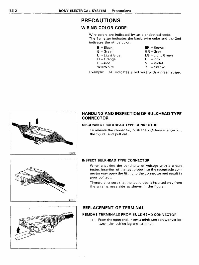
HANDLING AND INSPECTION OF BULKHEAD TYPECONNECTOR
DISCONNECT BULKHEAD TYPE CONNECTOR
To remove the connector, push the lock levers, shown ...the figure, and pull out.
M7615
INSPECT BULKHEAD TYPE CONNECTOR
When checking the continuity or voltage with a circuittester, insertion of the test probe into the receptacle connector may open the fitting to the connector and result inpoor contact.
Therefore, ensure that the test probe is inserted only fromthe wire harness side as shown in the figure.
BE0013
REPLACEMENT OF TERMINAL
REMOVE TERMINALS FROM BULKHEAD CONNECTOR
(a) From the open end, insert a miniature screwdriver between the locking lug and terminal.
BODY ELECTRICAL SYSTEM - Precautions BE-3
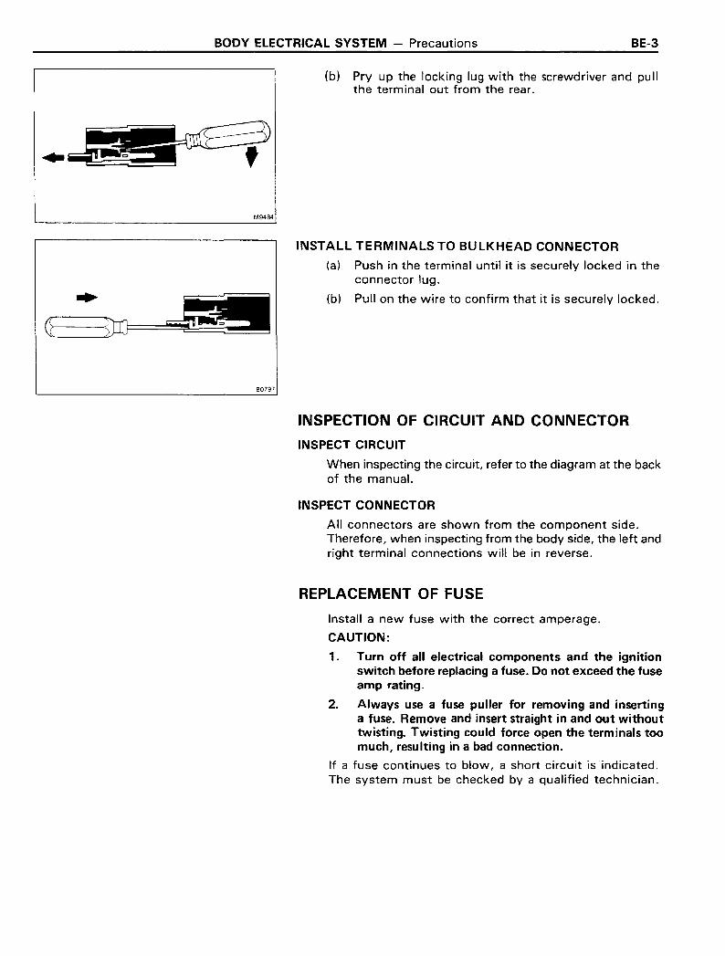
(b) Pry up the locking lug with the screwdriver and pullthe terminal out from the rear.
M9484
INSTALL TERMINALS TO BULKHEAD CONNECTOR
(a) Push in the terminal until it is securely locked in theconnector lug.
(b) Pull on the wire to confirm that it is securely locked.
80797
INSPECTION OF CIRCUIT AND CONNECTOR
INSPECT CIRCUIT
When inspecting the circuit, refer to the diagram at the backof the manual.
INSPECT CONNECTOR
All connectors are shown from the component side.Therefore, when inspecting from the body side, the left andright terminal connections will be in reverse.
REPLACEMENT OF FUSE
Install a new fuse with the correct amperage.
CAUTION:
1. Turn off all electrical components and the ignitionswitch before replacing a fuse. Do not exceed the fuseamp rating.
2. Always use a fuse puller for removing and insertinga fuse. Remove and insert straight in and out withouttwisting. Twisting could force open the terminals toomuch, resulting in a bad connection.
If a fuse continues to blow, a short circuit is indicated.The system must be checked by a qualified technician.

BE-4 BODY ELECTRICAL SYSTEM - Precautions
RESET OF CIRCUIT BREAKER
1. REMOVE CIRCUIT BREAKER
80798
2. RESET CIRCUIT BREAKER
(a) Insert the needle into the reset hole and push it in.
(b) Using an ohmmeter, check that there is continuity between both terminals of the circuit breaker.
If there is no continuity, replace the circuit breaker.
8E00158E0014
3. INSTALL CIRCUIT BREAKER
Install the circuit breaker.
NOTE: If the circuit breaker continues to cut out, a sh r -+
circuit is indicated. The system must be checked b ,qualified technician.
80798

BODY ELECTRICAL SYSTEM - Location of Switches and Relays BE-5
LOCATION OF SWITCHES ANDRELAYSENGINE COMPARTMENT SWITCHES ANDRELAYS
Oil Pressure Switch
4WD Indicator Switch
~~ Neutral Start Switch
~ Oil Pressure Sender Gauge
Water TemperatureSender Gauge
~
BE0510
BE-6 BODY ELECTRICAL SYSTEM - Location of Switches and Relays
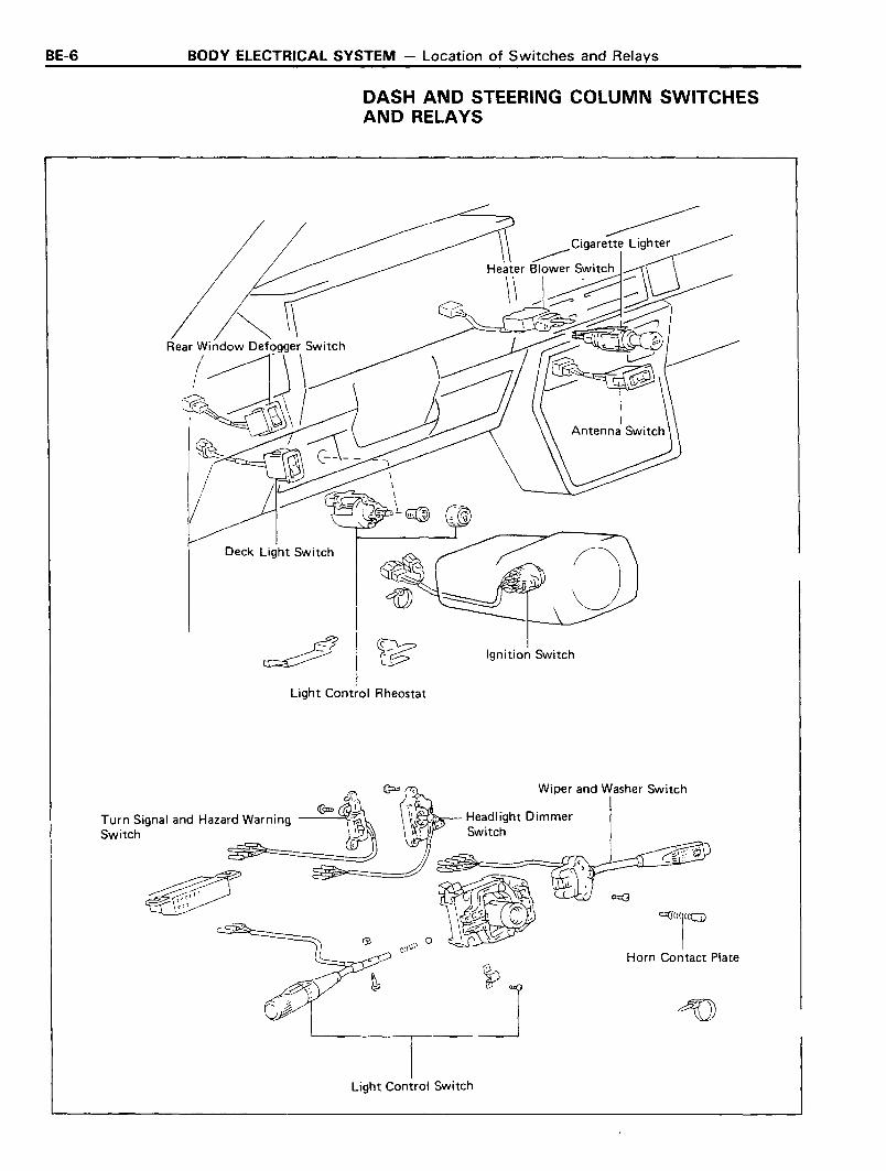
DASH AND STEERING COLUMN SWITCHESAND RELAYS
Deck Light Switch
Ignition Switch
Light Control Rheostat
<O(J("I"Gl
Horn Contact Plate
Wiper and Washer Switch
Turn Signal and Hazard Warning --~~Switch
Light Control Switch
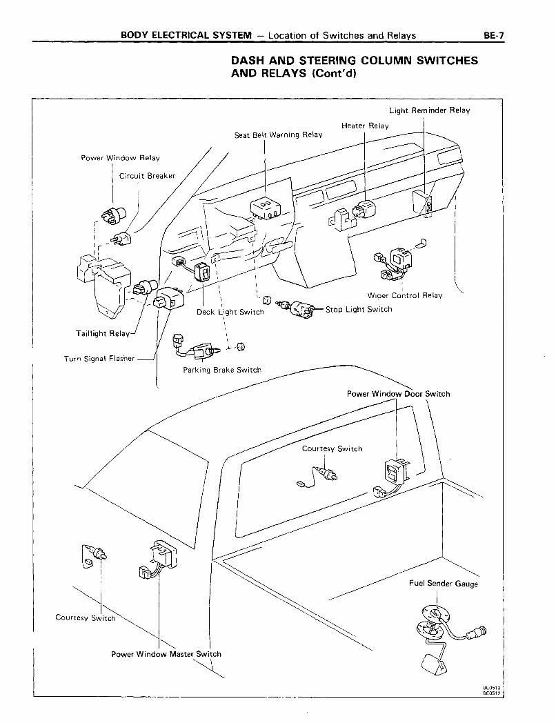
BODY ELECTRICAL SYSTEM - Location of Switches and Relays BE-7
DASH AND STEERING COLUMN SWITCHESAND RELAYS (Cont'd)
Light Rem inder Relay
Heater Relay
Fuel Sender Gauge
Power Window Door Switch
Circuit Breaker
Seat Belt Warning Relay
~Power Window Master Switch
~
Power Window Relay
Turn Signal Flasher
Courtesy Switch
BE0513BE0512

BE-8 BODY ELECTRICAL SYSTEM - Location of Switches and Relays
DASH AND STEERING COLUMN SWITCHESAND RELAYS (Cont'd)
Actuator
"'l~~)..J..,L-=~~;:-----=:::::::===='i~TCru ise ControlMain Switch
Cru ise ControlComputer
Clutch Switch
Back Door Power WindowRegulator Switch
Power WindowMaster Switch
Defogger Relay
Power Window Door Switch
Fuel Sender Gauge
Back Door Control Switch
Back Door Unlock Warning Switch
BE02S1

BODY ELECTRICAL SYSTEM - Switches BE-9
AMI ACC IG I STI
AM 2 IG 2 ST2
H·8-2H·2·2
SWITCHES
Ignition SwitchINSPECTION OF IGNITION SWITCH
INSPECT SWITCH CONTINUITY
Inspect the switch continuity between terminals.
~(Wire AM, ACC IGl ST, AM2 IG2 ST2 H I
SWi.t~h color)(B-R) (L-R) (S-Y) (S-W) (BR) (BR-W) (SR-R) (G-W) (G-W)posItIon
LOCK
ACC 0--{)
ON 0--0-~ 0-~
START {)-r-o 0--0--0C)
normalc·Eco push 0-~~
If continuity is not as specified, replace the switch.
Combination SwitchINSPECTION OF COMBINATION SWITCH
1. INSPECT LIGHT CONTROL SWITCH AND HEADLIGHTDIMMER SWITCH
Inspect the switch continuity between terminals.
light control switch
~10 or 11 10 or 11 4
(Wire EL T H~wi:~h olor) (W) (W) (R)posItIOn
OFFTAIL 0 -0HEAD 0 '" ()'-'
Headlight dimmer switch
~13 6 5 12
(Wire ED HL HU HFSWi~~h alar) (W-B) (R-G) (R-Y) (R-W)position
Flash 0 '" -0'-'
Low Beam 0 ()
High Beam 0 ()
If continuity is not as specified, replace the switch.
BE-10 BODY ELECTRICAL SYSTEM - Switches
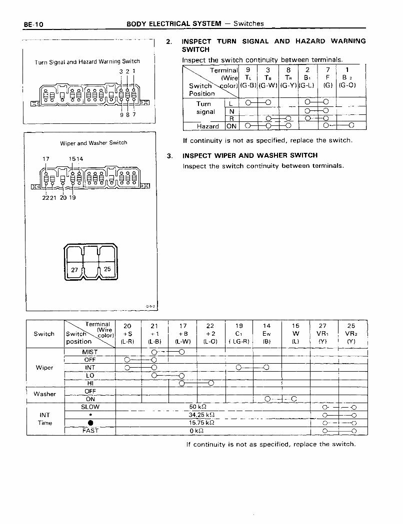
Turn Signal and Hazard Warning Switch
321
§It~~~14Jb
987
Wiper and Washer Switch
G-5-2
2.
3.
INSPECT TURN SIGNAL AND HAZARD WARNINGSWITCH
Inspect the switch continuity between terminals.
Terminal 9 3 8 2 7 1(Wire TL Ts TR B, F B 2
Switch alar) (G-B) (G-W) (G-Y) (G-L) (G) (G-O)
Position
Turn I--=-L-+-_--+__+-_-+-_--+_--I~--_l
signal ~N-+----+-=__+-_=_-+-~--+__=__~--__lR
Hazard ON
If continuity is not as specified, replace the switch.
INSPECT WIPER AND WASHER SWITCH
Inspect the switch continuity between terminals.
~20 21 17 22 19 14 15 27 25
. (WireSwitch SWI~C.ti color) +S +1 +8 +2 C, Ew W VR, VR2
position (L-R) (L-B) (L-W) (L-O) ( LG-R) (B) (L) (Y) (Y)
MIST 0 -0OFF C 0
Wiper INT 0 D 0 DLO 0: ()HI 0 D
Washer OFFON 0 0
SLOW 50 kn 0 DINT • 34.25 kn 0 D
Time • 15.75 kn 0 -0FAST OkQ 0 -0
If continuity is not as specified, replace the switch.
BODY ELECTRICAL SYSTEM - Switches
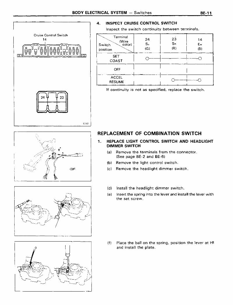
4. INSPECT CRUISE CONTROL SWITCH
Inspect the switch continuity between terminals.
BE-11
Cruise Control Switch14
~24 23
(Wire 14
SWi.t~h color) Ss SR Ew
position (G) (R) (8)
SETCOAST
OFF
ACCELRESUME
If continuity is not as specified, replace the switch.
G-5-2
REPLACEMENT OF COMBINATION SWITCH
1. REPLACE LIGHT CONTROL SWITCH AND HEADLIGHTDIMMER SWITCH
(a) Remove the terminals from the connector.(See page BE-2 and BE-6)
(b) Remove the light control switch.
(c) Remove the headlight dimmer switch.
(d) Install the headlight dimmer switch.
(e) Insert the spring into the lever and install the lever withthe set screw.
(f) Place the ball on the spring, position the lever at HIand install the plate.

BE-12 BODY ELECTRICAL SYSTEM - Switches
(g) Insure that the switch operates smoothly.
(h) Install the terminals to the connector.(See page BE-3)
2. REPLACE TURN SIGNAL AND HAZARDWARNING SWITCH
(a) Remove the terminals from the connector.(See page BE-2)
(b) Remove the turn signal and hazard warning switch.
(c) Install the turn signal and hazard warning switch.
(d) Install the terminals to the connector.(See page BE-3)
3. REPLACE WIPER AND WASHER SWITCH
(a) Remove the terminals from the connector.(See page BE-2)
(b) Remove the wiper control switch and washer switc
(c) Install the wiper control switch and washer switch.
(d) Install the terminals to the connector.(See page BE-3)

BODY ELECTRICAL SYSTEM - Lighting
LIGHTINGTroubleshooting
BE-13
Problem Possible cause Remedy Page
Only one light does Light bulb burned out Replace bulbnot light Socket, wire or ground faulty Repair as necessary
Headlights do not light Fusible link blown Replace fusible link
Headlight control relay faulty Check relay BE-14
Light control/dimmer switch faulty Check switch BE-9
Wiring or ground faulty Repair as necessary
High beam headlights Light control/dimmer switch faulty Check switch BE-9or headlight flashers do Wiring or ground faulty Repair as necessarynot operate
Tail, parking and TAIL fuse blown Replace fuse and check for short BE·3license light do not Fusible link blown Replace fusible linklight Tailight control relay faulty Check relay BE-14
Light control switch faulty Check switch BE-9
Wiring or ground faulty Repair as necessary
Stop lights do not STOP fuse blown Replace fuse and check for short BE-3light Stop light switch faulty Adjust or replace switch
Wiring or ground faulty Repair as necessary
Stop lights stay on Stop light switch faulty Adjust or replace switch
Instrument lights do Light control rheostat faulty Check rheostat BE-14not light (taillights Wiring or ground faulty Repair as necessarylight)
Turn signal does not Turn signal switch faulty Check switch BE-l0flash on one side Wiring or ground faulty Repair as necessary
Turn signals do not HAZ-HORN fuse blown Replace fuse and check for short BE-3operate Turn signal flasher faulty Check flasher BE-15
Turn signal/hazard switch faulty Check switch BE-l0
Wiring or ground faulty Repair as necessary
Hazard warning lights HAZ-HORN fuse blown Replace fuse and check for short BE-3do not operate Turn signal flasher faulty Check flasher BE-15
Turn signal/hazard switch faulty Check switch BE-l0
Wiring or ground faulty Repair as necessary

BE-14 BODY ELECTRICAL SYSTEM - Lighting
Headlight Control RelayINSPECTION OF HEADLIGHT CONTROL RELA'
1. INSPECT RELAY CONTINUITY
(a) Check that there is continuity between terminals 1 and3.
(b) Check that there is continuity between terminals 2 and4.
(c) Check that there is no continuity between terminals4 and 5.
If continuity is not as specified, replace the relay.
INSPECT RELAY OPERATION
(a) Apply battery voltage across terminals 1 and 3.
(b) Check that there is continuity between terminals 4 and5.
(c) Check that there is no continuity between terminals2 and 4.
If operation is not as specified, replace the relay.
2.
5 4
Continuity
DO
Continuity
Taillight Control RelayINSPECTION OF TAILLIGHT CONTROL RELAY
1. INSPECT RELAY CONTINUITY
(a) Check that there is continuity between terminals 1 and2.
(b) Check that there is no continuity between terminals2 and 3.
If continuity is not as specified, replace the relay.
2. INSPECT RELAY OPERATION
(a) Apply battery voltage across terminals 1 and 2.
(b) Check that there is continuity between terminals 2 and3.
If operation is not as specified, replace the relay.
Light Control RheostatINSPECTION OF LIGHT CONTROL RHEOSTAT
INSPECT RESISTANCE OF RHEOSTATPoint Resistance (0) I
Full counterclockwise 00
Midpoint Approx. 7 IFull clockwise 0 I
If resistance is not as specified, replace the rheostat.
BODY ELECTRICAL SYSTEM - Lighting BE-15
IA-32
Battery
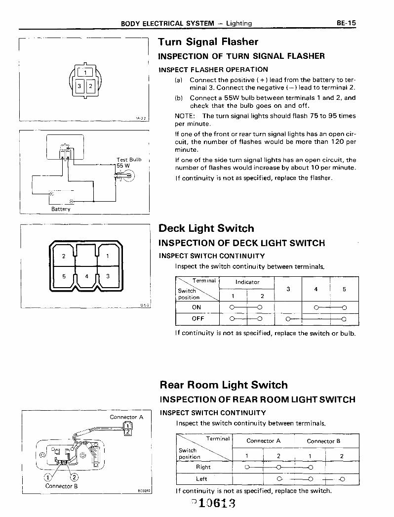
Turn Signal FlasherINSPECTION OF TURN SIGNAL FLASHER
INSPECT FLASHER OPERATION
(a) Connect the positive (+) lead from the battery to terminal 3. Connect the negative (-) lead to terminal 2.
(b) Connect a 55W bulb between terminals 1 and 2, andcheck that the bulb goes on and off.
NOTE: The turn signal lights should flash 75 to 95 timesper minute.
If one of the front or rear turn signal lights has an open circuit, the number of flashes would be more than 120 perminute.
If one of the side turn signal lights has an open circuit, thenumber of flashes would increase by about 10 per minute.
If continuity is not as specified, replace the flasher.
G-5-2
Deck Light SwitchINSPECTION OF DECK LIGHT SWITCHINSPECT SWITCH CONTINUITY
Inspect the switch continu ity between terminals.
~Indicator
Switch 3 4 5position 1 2
ON -0
OFF
If continuity is not as specified, replace the switch or bulb.
1
Connector B
Connector A
BE02B2
Rear Room Light SwitchINSPECTION OF REAR ROOM LIGHT SWITCH
INSPECT SWITCH CONTINUITY
Inspect the switch continu ity between term inals.
~Connector A Connector B
Switchposition 1 2 1 2
Right
Left D~
If continuity is not as specified, replace the switch.
Dl0613
BE-16 BODY ELECTRICAL SYSTEM - Lighting
BE0543
BE0544
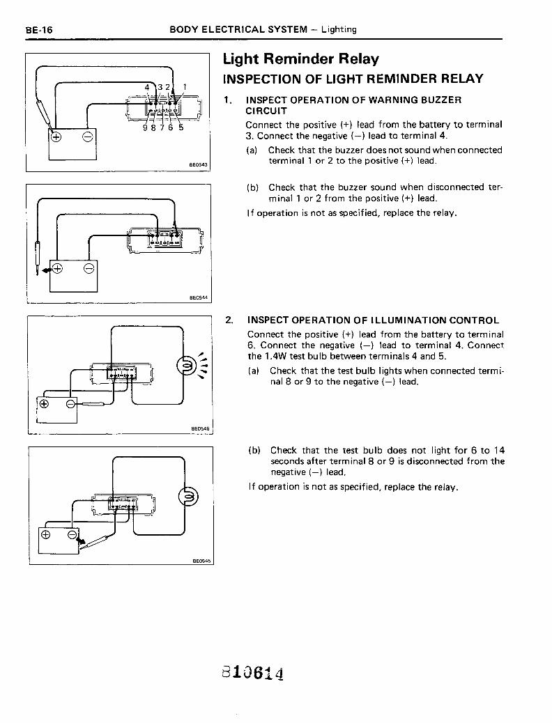
Light Reminder RelayINSPECTION OF LIGHT REMINDER RELAY
1. INSPECT OPERATION OF WARNING BUZZERCIRCUIT
Connect the positive (+) lead from the battery to terminal3. Connect the negative (-) lead to terminal 4.
(a) Check that the buzzer does not sound when connectedterminal 1 or 2 to the positive (+) lead.
(b) Check that the buzzer sound when disconnected terminal 1 or 2 from the positive (+) lead.
If operation is not as specified, replace the relay.
BE0546
BE0545
2. INSPECT OPERATION OF ILLUMINATION CONTROL
Connect the positive (+) lead from the battery to terminal6. Connect the negative (-) lead to terminal 4. Connectthe 1AW test bulb between terminals 4 and 5.
(a) Check that the test bulb lights when connected terminal 8 or 9 to the negative (-) lead.
(b) Check that the test bulb does not light for 6 to 14seconds after terminal 8 or 9 is disconnected from thenegative (-) lead.
If operation is not as specified, replace the relay.
810614

BODY ELECTRICAL SYSTEM - Wipers and Washers
WIPERS AND WASHERSTroubleshooting
BE-17
PageProblem Possible cause Remedy
Front Rear
Wipers do not operate Fuse blown Replace fuse and check for short BE-3 BE-3of return to off Wiper motor faulty Check motor BE-18 BE-20position Wiper switch faulty Check switch BE-l0 BE-19
Wiring or ground faulty Repair as necessary
Wipers do not operate Wiper control relay faulty Check relay BE-17in INT position Wiper switch faulty Check switch BE-l0 BE-19
Wi per motor fau Ity Check motor BE-18 BE-20
Wiring or ground faulty Repair as necessary
Washer does not Washer hose or nozzle clogged Repair as necessary
operate Washer motor fau Ity Replace motor
Washer switch faulty Check switch BE-l0 BE-19
Wiring faulty Repair as necessary
n.
o
Wiper Control RelayINSPECTION OF WIPER CONTROL RELAY(INT. Invariable Type)
INSPECT RELAY OPERATION
(a) Connect the positive (+ ) lead from the battery to terminal 3. Connect the negative (-) lead to terminal 2.
(b) Check that there is continuity between terminals 1 and4 once each 3 to 5 seconds.
If operation is not as specified, replace the relay.
rf?1ill]~
$-6-2-B H-4-2
INSPECTION OF WIPER CONTROL RELAY(INT. Variable Type)
1. INSPECT INTERMITTENT OPERATION OF RELAY
(a) Connect the positive (+) lead from the battery to terminal 3. Connect the negative (-) lead to terminal 5.
(b) With terminal 2 and 5 connected, check that continuity between 1 and 3 is as shown in the followingdiagram.
~oo IC'I+---..Jo
~Connect terminals
Time (sees.) 8 and 10
+0.3Duration of continuity 0.8
-0.4
Duration of non- 2.0±0.6continuity
If operation is not as specified, replace the relay.

BE-18 BODY ELECTRICAL SYSTEM - Wipers and Washers
3
2. INSPECT WASHER CIRCUIT OF RELAY
(a) Connect the positive ( + ) lead from the battery to te"minal 3. Connect the negative (-) lead to terminal L
(b) Inspect continuity between terminals 1 and 3 asfollows.
o
Ol~---o
BE0435
BE0436
BE0437
I Between terminals IBetween terminalsTime (seconds) 1 and 3 Time (seconds) 1 and 3
Connect terminals Disconnect terminals
5 and 7 I Continuity1 5 and 7 IContinuity IO.5±'O.2 + 2.2±'O.5 ~
INo Continuity I I No Continuity1If operation is not as specified, replace the relay.
Front Wiper MotorINSPECTION OF FRONT WIPER MOTOR1. INSPECT THAT MOTOR TURNS AT LOW SPEED
(a) Disconnect the connector from the upper motor.
(b) Connect the positive (+) lead from the battery to terminal 2. Connect the negative (-) lead to the motorbody.
(c) Check that the motor turns at low speed.
2. INSPECT THAT MOTOR TURNS AT HIGH SPEED
(a) Connect the positive (+) lead from the battery to terminal 1. Connect the negative (-) lead to the motorbody.
(b) Check that the motor turns at high speed.
3. INSPECT THAT MOTOR STOPS RUNNING AT STOPPOSITION
(a) Turn the motor at low speed.
(b) Stop motor operation at anywhere except the stopposition by disconnecting the battery terminals.
810595
BODY ELECTRICAL SYSTEM - Wipers and Washers BE-19
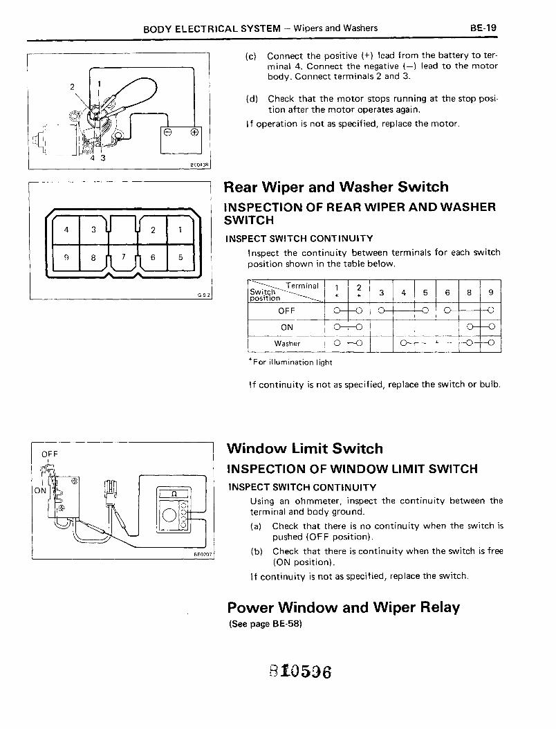
(c) Connect the positive (+) lead from the battery to terminal 4. Connect the negative (-) lead to the motorbody. Connect terminals 2 and 3.
(d) Check that the motor stops running at the stop position after the motor operates again.
I f operation is not as specified, replace the motor.
BE043B
4
9
3
8
2
6 5
G·9·2
Rear Wiper and Washer SwitchINSPECTION OF REAR WIPER AND WASHERSWITCH
INSPECT SWITCH CONTINUITY
I nspect the continuity between terminals for each switchposition shown in the table below.
~1 2Switch 3 4 5 6 8 9
position * *
OFF 0--0 0 D
ON 0--0 0--D
Washer 0---1kJ -o--l~
* For illumination light
If continuity is not as specified, replace the switch or bulb.
OFF
BE0207
Window Limit SwitchINSPECTION OF WINDOW LIMIT SWITCH
INSPECT SWITCH CONTINUITYUsing an ohmmeter, inspect the continuity between theterminal and body ground.
(a) Check that there is no continuity when the switch ispushed (OFF position).
(b) Check that there is continuity when the switch is free(ON position).
If continu ity is not as specified, replace the switch.
Power Window and Wiper Relay(See page BE-58)
810596

BE-20 BODY ELECTRICAL SYSTEM - Wipers and Washers
Rear Wiper MotorINSPECTION OF REAR WIPER MOTOR
1. INSPECT THAT MOTOR TURNS
(a) Disconnect the connector from the wiper motor.
(b) Connect the positive (+) lead from the battery toterminal 6. Connect the negative (-) lead to terminal5.
C7613 (c) Check that the motor turns.L.- ---J
1\ \
MI :
C7615
2. INSPECT THAT MOTOR TURNS RUNNING AT STOPPOSITION
(a) Turn the motor.
(b) Stop motor operation at anywhere except the stopposition by disconnecting the battery terminals.
(c) Connect the positive (+) lead from the battery to terminal 3. Connect the negative (-) lead to terminal 5.Connect the terminals 2 and 5.
(d) Check that the motor stops running at stop positiafter the motor operates again.
If operation is not as specified, replace the motor.
810597
BODY ELECTRICAL SYSTEM - Instruments and Sender Gauges BE-21
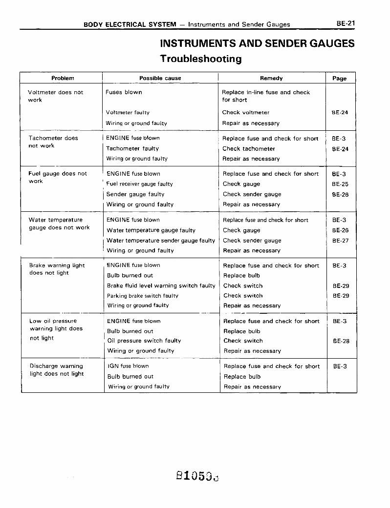
INSTRUMENTS AND SENDER GAUGES
Troubleshooting
Problem Possible cause Remedy Page
Voltmeter does not Fuses blown Replace in-line fuse and checkwork for short
Voltmeter faulty Check voltmeter BE-24
Wiring or ground faulty Repair as necessary
Tachometer does ENGINE fuse blown Replace fuse and check for short BE-3not work Tachometer faulty Check tachometer BE-24
Wiring or ground faulty Repair as necessary
Fuel gauge does not ENGINE fuse blown Replace fuse and check for short BE-3work Fuel receiver gauge faulty Check gauge BE-25
Sender gauge faulty Check sender gauge BE-26
Wiring or ground faulty Repair as necessary
Water temperature ENGINE fuse blown Replace fuse and check for short BE-3gauge does not work Water temperature gauge faulty Check gauge BE-26
Water temperature sender gauge faulty Check sender gauge BE-27
Wiring or ground faulty Repair as necessary
Brake warning light ENGINE fuse blown Replace fuse and check for short BE-3does not light Bulb burned out Replace bulb
Brake fluid level warning switch faulty Check switch BE-29
Parking brake switch faulty Check switch BE-29
Wiring or ground faulty Repair as necessary
Low oil pressure ENGINE fuse blown Replace fuse and check for short BE-3warning light does Bulb burned out Replace bulbnot light Oil pressure switch faulty Check switch BE-28
Wiring or ground faulty Repair as necessary
Discharge warning IGN fuse blown Replace fuse and check for short BE-3light does not light Bulb burned out Replace bulb
Wiring or ground faulty Repair as necessary
8105Du
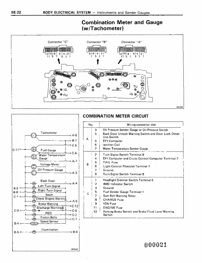
BE-22 BODY ELECTRICAL SYSTEM - Instruments and Sender Gauges
Combination Meter and Gauge(w/Tachometer)
Connector "c"
~11 9 7 5 3 1
\
Connector" 8"
87 5 3 1
t
Connector"A"
~12110/81 614121
11 9 7 5 3 1
BE0208
COMBINATION METER CIRCUIT
No. Wiring connector side I3 Oil Pressure Sender Gauge or Oil Pressure Switch4 Back Door Unlock Warning Switch and Door Lock Detec-
Ation Switch
5 EFI Computer6 Ignition Coil7 Water Temperature Sender Gauge
2 Turn Signal Switch Terminal 94 EFI Computer and Cruise Control Computer Terminal 7
B5 TAIL Fuse6 Light Control Rheostat Terminal 17 Ground8 Turn Signal Switch Terminal 8
1 Headlight Dimmer Switch Terminal 62 4WD Indicator Switch4 Ground
C5 Fuel Sender Gauge Terminal 17 Seat Belt Warning Relay8 CHARGE Fuse
I 9 IGN Fuse11 ENGINE Fuse12 Parking Brake Switch and Brake Fluid Level Warning
Switch
C-9
Back Door
Left Turn SignalB-2
Right Turn Signal8-8 0--""'1 '----¥()\.r----=----.......:::....---..
BeamC-l 0---"1 '---tJO'-t-- -------..Check Engine Warning
t-----1t"O'T--------'"I'"--o A-58rake Warning
.-----<fJo'+--D-js-c-h-a-rg-e-W-a-r-=n'-in-g"""'-;I '---<l C·12'"---f.I[N-~- -.-.-.rl'--o C-8
4WDt------1~-------....II'---OC-2
Fasten 8elts1......------f"lN--------...If'---o C-7
Speed Sensor8 -4 o-----+~--+~---------J
Illumination8-5 o~-----+'®+----------o8-6
800021BE0550

BODY ELECTRICAL SYSTEM - Instruments and Sender Gauges BE-23
Combination Meter and Gauge(w/o Tachometer)
Connector "C"
~321301281 261241 221
31 29 27 25 23 21
Connector liB"
~8\ 6 \ 4 I 2 \
7 5 3 1
t
Connector IIA"
--1211018\ 61412\11 9 7 5 3 1
BE0210
COMBINATION METER CIRCUIT
No. Wiring connector side
3 Oil Pressure Switch
4 Back Door Unlock Warning Switch and Door Lock Detec-A tion Switch
5 EFI Computer7 Water Temperature Sender Gauge
2 Turn Signal Switch Terminal 94 EF I Computer and Cruise Control Computer Terminal 7
B5 TAIL Fuse
6 Light Control Rheostat Terminal 1
7 Ground
8 Turn Signal Switch Terminal 8
1 Headlight Dimmer Switch Terminal 52 4WD Indicator Switch4 Ground
C5 Fuel Sender Gauge Terminal 1
7 Seat Belt Warning Relay8 CHARGE Fuse9 IGN Fuse
11 ENGINE Fuse
12 Parking Brake Switch and Brake Fluid Level WarningSwitch
C-4
C-llFuel Gauge
C-5Water TemperatureGauge
A-7
B-2Left turn Signal
B-7
B-8Right Turn Signal
C-l Beam
A-3Check Engine Warning
A-5Brake Warning
C-12Discharge WarningC-9 C-8
4WDC-2
Fasten BeltsC-7
Back DoorA-4
B-4Speed Sensor
® Illuminationo B-6B-5 0
800020
BE0549
BE-24 BODY ELECTRICAL SYSTEM - Instruments and Sender Gauges
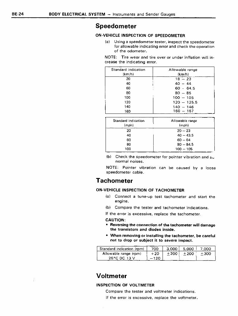
SpeedometerON-VEHICLE INSPECTION OF SPEEDOMETER
(a) Using a speedometer tester, inspect the speedometerfor allowable indicating error and check the operationof the odometer.
NOTE: Tire wear and tire over or under inflation will increase the indicating error.
Standard indication Allowable range(km/h) (km/h)
20 18 - 2340 40 - 4460 60 - 64.580 80 - 85
100 100 - 105120 120 - 125.5140 140 - 146160 160 - 167
Standard indication Allowable range(mph) (mph)
20 20 -2340 40 - 43.560 60 -6480 80 - 84.5
100 100 - 105
(b) Check the speedometer for pointer vibration and avnormal noises.
NOTE: Pointer vibration can be caused by a loosespeedometer cable.
TachometerON-VEHICLE INSPECTION OF TACHOMETER
(a) Connect a tune-up test tachometer and start theengine.
(b) Compare the tester and tachometer indications.
If the error is excessive, replace the tachometer.
CAUTION:• Reversing the connection of the tachometer will damage
the transistors and diodes inside.
• When removing or installing the tachometer, be carefulnot to drop or subject it to severe impact.
Standard indication (rpm) 700 3,000 5,000 7,000Allowable range (rpm) +20 ±200 ±200 ±300
25°C DC 13 V -120
VoltmeterINSPECTION OF VOLTMETER
Compare the tester and voltmeter indications.
If the error is excessive, replace the voltmeter.

BODY ELECTRICAL SYSTEM - Instruments and Sender Gauges
Fuel GaugeINSPECTION OF FUEL GAUGE
BE-25
Fuel Receiver
I.. Gauge Test Bulb 3.4 W
gnltlon "ISwitch ~ ~-
1.
2.
INSPECT RECEIVER GAUGE OPERATION(wi Tachometer)
(a) Disconnect the connector from the fuel sender gauge.Turn the ignition switch on. Check that the receivergauge needle moves to the empty position.
(b) Connect a 3.4 W bulb between terminal 1 and bodyground. Check that the bulb lights and that thereceiver gauge needIe operates.
NOTE: Because of the silicon oil in the gauge, it will takeabout 90 seconds for the needle to stabilize.
If indications are not correct, remove and test the receivergauge.
MEASURE RECEIVER GAUGE RESISTANCE BETWEENTERMINALS (wi Tachometer)
Between terminals Resistance (0)
IG - FU Aoorox. 83FU - E Approx.156IG - E Approx.239
If each resistance value is not as shown in the table above,replace the receiver gauge.
Fuel Receiver Gauge
: Battery
I
4.5V
0 V 8
3. INSPECT RECEIVER GAUGE OPERATION(w/o Tachometer)
(a) Disconnect the connector from the fuel sender gauge.Connect the positive (+) lead from the voltmeter toterminal 1 and connect the negative (-) lead from thevoltmeter to terminal 2.
(b) Turn the ignition switch on. Check that the meterneedle vibrates near the 4.5 V position.
If voltage is not correct, remove and test the receiver gauge.
4. MEASURE RECEIVER GAUGE RESISTANCE(w/o Tachometer)
Using an ohmmeter, measure the resistance between terminals 1 and 2.
Resistance: Approx. 55 0
If resistance value is not as specified, replace the receivergauge.
810628

BE-26
2WD Short
2WD Long4WD4 RUNNER
BODY ELECTRICAL SYSTEI\'1 - Instruments and Sender Gauges
5. MEASURE RESISTANCE OF SENDER GAUGE
(a) Check that resistance changes as the float is movenfrom the top to bottom position.
(b) Measure the resistance between terminals 1 and 2.
2WD
Float position mm (in.) Resistance (0,)Short Deck Lonq Deck
F 47(1.85) 94.3 (3.71) 3+ 2-3
1/2 150 (5.91) 174.7 (6.88) 32.5±4.8E 245.1 (9.65) 256.7 (10.11) 110±7.7
4WDFloat position mm (in.)
Resistance (0,)65 liters 73 liters
F 105.7 (4.16) 114.3 (4.50) 3+ 2-3
1/2 196.2 (7.72) 214.7 (8.45) 32.5±4.8E 288.2 (11.35) 317.1 (12.48) 110±7.7
4 RUNNER
Float position mm (in.)Resistance (0,)
56 liters 65 liters
F 91.9 ( 3.62) 105.7 ( 4.16) 3+ 2-3
1/2 182.5 ( 7.19) 196.2 ( 7.72) 32.5 ± 4.8
E 262.0 (10.31) 288.2 (11.35) 110±7.7
If each resistance value is not as shown in the table abo'replace the sender gauge.
Water Temperature GaugeINSPECTION OF WATER TEMPERATURE GAUGE
Water Temperature Test Bulb 3.4WReceiver Gauge
IgnitionSwitch .
~-~
1. INSPECT RECEIVER GAUGE OPERATION(wI Tachometer)
(a) Disconnect the connector from the sender gauge.Ground the terminal through a 3.4 W bulb as shown.
(b) Turn the ignition switch on. Check that the bulb lightsand that the receiver gauge need Ie operates.
If indications are not correct, remove and test the receivergauge.
2. MEASURE RESISTANCE OF RECEIVER GAUGE(wi Tachometer)
Using an ohmmeter, measure the resistance betweenterminals.
If each resistance value is not as shown in the table below,replace the receiver gauge.
Between terminals Resistance (0)
IG -TU Approx. 135TU - E Approx. 138IG - E Approx. 273
BODY ELECTRICAL SYSTEM - Instruments and Sender Gauges BE-27
Water TemperatureReceiver Gauge
Jnition S,,:,,,itch
: Battery
T1
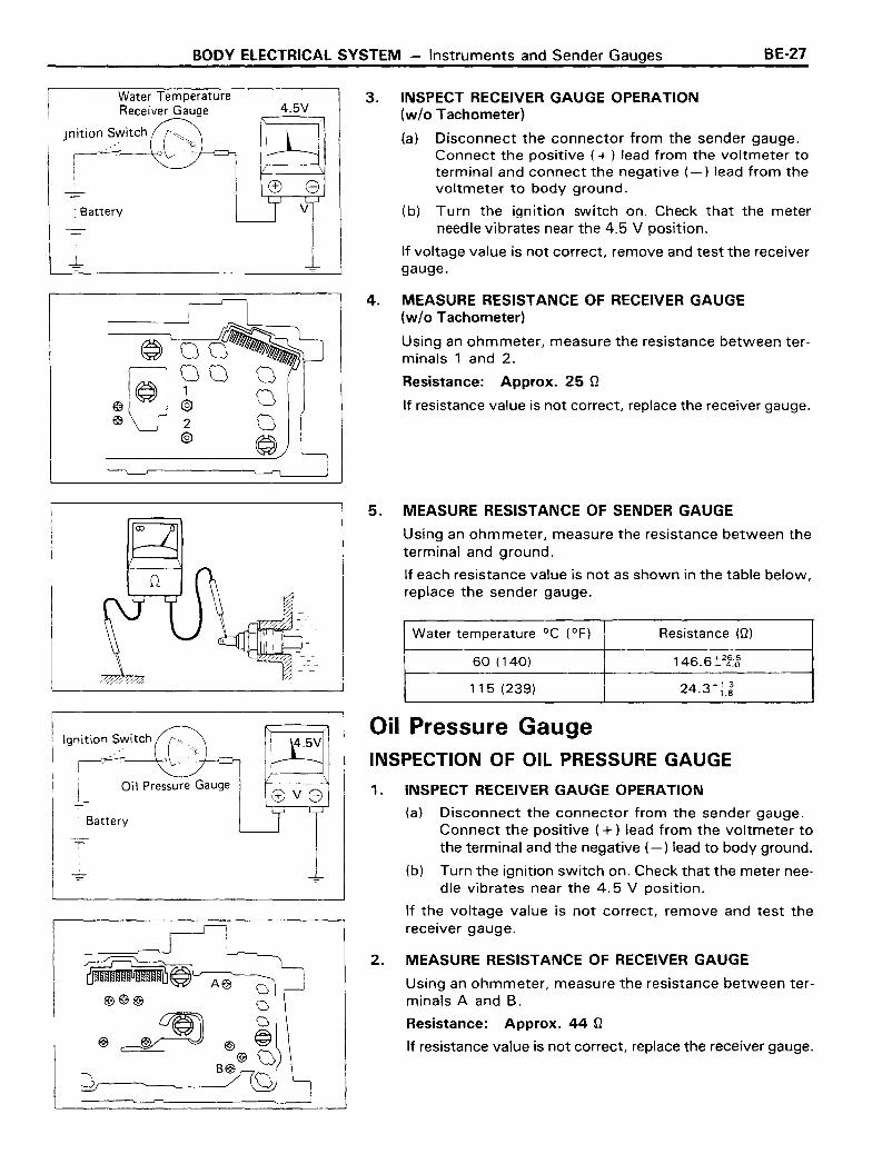
4.5V3. INSPECT RECEIVER GAUGE OPERATION
(w/o Tachometer)
(a) Disconnect the connector from the sender gauge.Connect the positive (+) lead from the voltmeter toterminal and connect the negative (-) lead from thevoltmeter to body ground.
(b) Turn the ignition switch on. Check that the meterneedle vibrates near the 4.5 V position.
If voltage value is not correct, remove and test the receivergauge.
4. MEASURE RESISTANCE OF RECEIVER GAUGE(w/o Tachometer)
Using an ohmmeter, measure the resistance between terminals 1 and 2.
Resistance: Approx. 25 nIf resistance value is not correct, replace the receiver gauge.
5. MEASURE RESISTANCE OF SENDER GAUGE
Using an ohmmeter, measure the resistance between theterminal and ground.
If each resistance value is not as shown in the table below,replace the sender gauge.
Water temperature °C (OF) Resistance (n)
60 (140) 146.6~2g:8
115 (239) 24.3~~:~
Ignition ~,:"itCh C~~
Gil pressu~eG:;'-';-au-1:"g=e
h
• Battery
I
Oil Pressure GaugeINSPECTION OF OIL PRESSURE GAUGE
1. INSPECT RECEIVER GAUGE OPERATION
(a) Disconnect the connector from the sender gauge.Connect the positive (+ ) lead from the voltmeter tothe terminal and the negative (-) lead to body ground.
(b) Turn the ignition switch on. Check that the meter needle vibrates near the 4.5 V position.
If the voltage value is not correct, remove and test thereceiver gauge.
2. MEASURE RESISTANCE OF RECEIVER GAUGE
Using an ohmmeter, measure the resistance between terminals A and B.
Resistance: Approx. 44 11
If resistance value is not correct, replace the receiver gauge.
BE-28 BODY ELECTRICAL SYSTEM - Instruments and Sender Gauges
Test Bulb (3.4 W)..... '\ I I
-
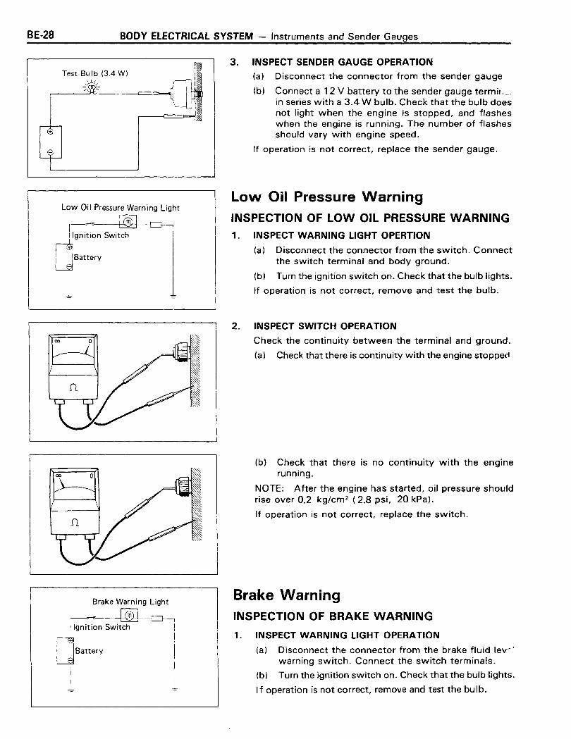
3. INSPECT SENDER GAUGE OPERATION
(a) Disconnect the connector from the sender gauge
(b) Connect a 12 V battery to the sender gauge termir ,__in series with a 3.4 W bulb. Check that the bulb doesnot light when the engine is stopped, and flasheswhen the engine is running. The number of flashesshould vary with engine speed.
If operation is not correct, replace the sender gauge.
Low Oil Pressure Warning Light
~gnition Switch
~Battery
I
!...J....
Brake Warning Light
~, I
Battery I
Low Oil Pressure WarningINSPECTION OF LOW OIL PRESSURE WARNING1. INSPECT WARNING LIGHT OPERTION
(a) Disconnect the connector from the switch. Connectthe switch terminal and body ground.
(b) Turn the ignition switch on. Check that the bulb lights.
If operation is not correct, remove and test the bulb.
2. INSPECT SWITCH OPERATION
Check the continuity between the terminal and ground.
(a) Check that there is continuity with the engine stopped
(b) Check that there is no continuity with the enginerunning.
NOTE: After the engine has started, oil pressure shouldrise over 0.2 kg/cm 2 (2.8 psi, 20 kPa).
If operation is not correct, replace the switch.
Brake WarningINSPECTION OF BRAKE WARNING
1. INSPECT WARNING LIGHT OPERATION
(a) Disconnect the connector from the brake fluid lev~'
warning switch. Connect the switch terminals.
(b) Turn the ignition switch on. Check that the bulb lights.
If operation is not correct, remove and test the bulb.

BODY ELECTRICAL SYSTEM - Instruments and Sender Gauges BE-29
2. INSPECT OPERATION OF BRAKE FLUID LEVELWARNING SWITCH
Inspect the switch operation when the switch is OFF (floatup) and when the switch is ON (float down).
If operation is not correct, replace the switch.
oo o
3. INSPECT OPERATION OF PARKING BRAKE SWITCH
Using an ohmmeter, inspect the continuity between theterminals.
(a) Check that there is continuity when the switch is free(parking brake lever pulled).
(b) Check that there is no continuity when the switch pinis pushed (parking brake lever returned).
If operation is not correct, replace the switch.
4WD Indicator
.'gnition Switch
qsatterv
I
-+
4WD IndicatorINSPECTION OF 4WD INDICATOR
1. INSPECT INDICATOR LIGHT OPERATION
(a) Disconnect the connector from the 4WD indicatorswitch. Connect the switch terminal and body ground.
(b) Turn the ignition switch on. Check that the bulb lights.
If operation is not correct, remove and test the bulb.
o o
o
2. INSPECT 4WD INDICATOR SWITCH OPERATION
Using an ohmmeter, inspect the continuity between theterminal and body.
(a) Check that there is continuity when the switch pinis pushed.
(b) Check that there is no continuity when the switch isfree.
If operation is not correct, replace the switch.
BE-30 BODY ELECTRICAL SYSTEM - Rear Window Dofogger
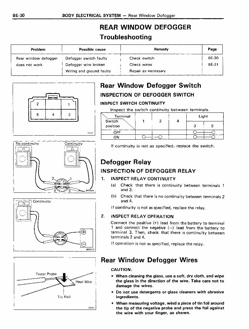
REAR WINDOW DEFOGGER
Troubleshooting
Problem Possible cause Remedy Page
Rear window defogger Defogger switch faulty Check switch BE-3D
does not work Defogger wire broken Check wires BE-31
Wiring and ground faulty Repair as necessary
2
Rear Window Defogger SwitchINSPECTION OF DEFOGGER SWITCH
INSPECT SWITCH CONTINUITY
Inspect the switch continuity between terminals.5
No continuity
C][]
4 3
Continuity
C][]
H62
~ Terminal Light
Switch ~ 1 2 4position 3 5
OFF 0 -0ON 0 -0 0 0
If continuity is not as specified, replace the switch.
Defogger RelayINSPECTION OF DEFOGGER RELAY
o
oContinuity
8BEOO10
1.
2.
INSPECT RELAY CONTINUITY
(a) Check that there is continuity between terminalsand 3.
(b) Check that there is no continuity between terminals 2and 4.
If continuity is not as specified, replace the relay.
INSPECT RELAY OPERATION
Connect the positive (+) lead from the battery to terminal1 and connect the negative (-) lead from the battery toterminal 3. Then, check that there is continuity betweenterminals 2 and 4.
If operation is not as specified, replace the relay.
Rear Window Defogger WiresCAUTION:
• When cleaning the glass, use a soft, dry cloth, and wipethe glass in the direction of the wire. Take care not todamage the wires.
• Do not use detergents or glass cleaners with abrasiveingredients.
• When measuring voltage, wind a piece of tin foil around'-- S_61---J61 the tip of the negative probe and press the foil against
the wire with your finger, as shown.
BODY ELECTRICAL SYSTEM - Rear Window Defogger BE-31
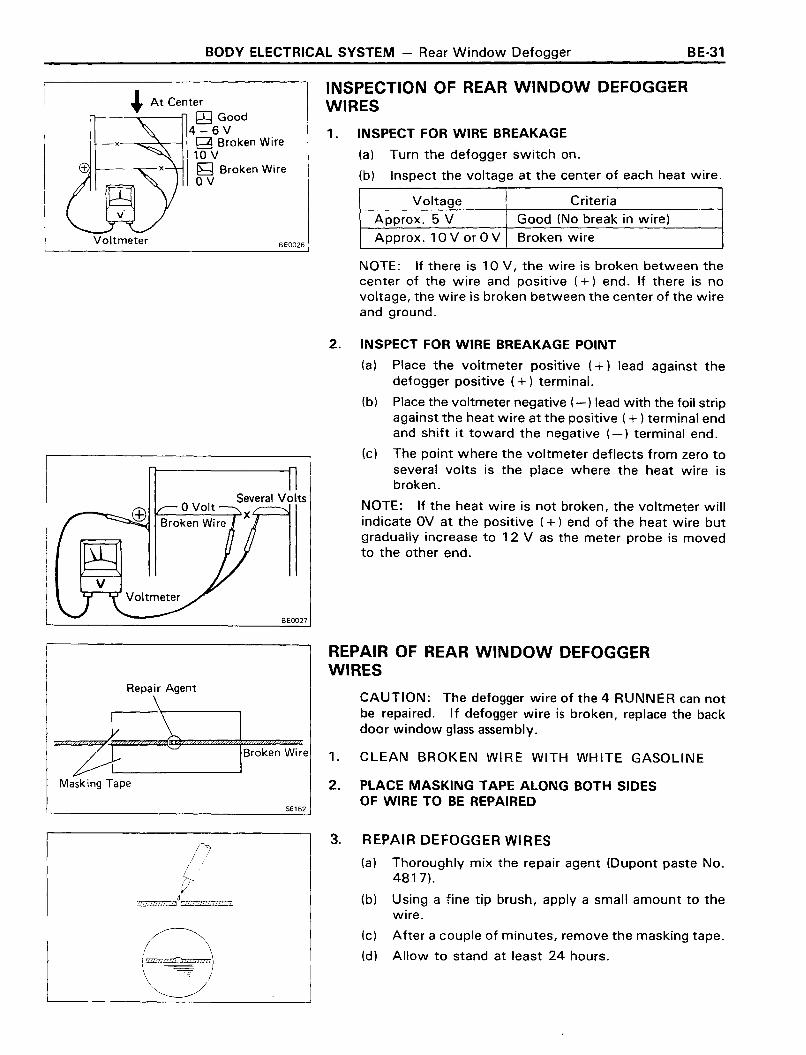
Voltage Criteria
Approx. 5 V Good (No break in wire)
Approx. 10 V or 0 V Broken wire
1. INSPECT FOR WIRE BREAKAGE
(a) Turn the defogger switch on.
(b) Inspect the voltage at the center of each heat wire.
INSPECTION OF REAR WINDOW DEFOGGERWIRES
BE0026
~ At Center~ Good
4-6V-x g Broken Wire
10 V~ Broken WireOV
Voltmeter
NOTE: If there is 10 V, the wire is broken between thecenter of the wire and positive (+) end. If there is novoltage, the wire is broken between the center of the wireand ground.
Several VoltsI'-----~x
BEoon
2. INSPECT FOR WIRE BREAKAGE POINT
(a) Place the voltmeter positive (+) lead against thedefogger positive (+) terminal.
(b) Place the voltmeter negative (-) lead with the foil stripagainst the heat wire at the positive ( + ) terminal endand shift it toward the negative (-) terminal end.
(c) The point where the voltmeter deflects from zero toseveral volts is the place where the heat wire isbroken.
NOTE: If the heat wire is not broken, the voltmeter willindicate OV at the positive (+) end of the heat wire butgradually increase to 12 V as the meter probe is movedto the other end.
REPAIR OF REAR WINDOW DEFOGGERWIRES
Masking Tape
56162
CAUTION: The defogger wire of the 4 RUNNER can notbe repaired. If defogger wire is broken, replace the backdoor window glass assembly.
1. CLEAN BROKEN WIRE WITH WHITE GASOLINE
2. PLACE MASKING TAPE ALONG BOTH SIDESOF WIRE TO BE REPAIRED
8
3. REPAIR DEFOGGER WIRES
(a) Thoroughly mix the repair agent (Dupont paste No.4817).
(b) Using a fine tip brush, apply a small amount to thewire.
(c) After a couple of minutes, remove the masking tape.
(d) Allow to stand at least 24 hours.

BE-32 BODY ELECTRICAL SYSTEM - Heater
HEATER
Troubleshooting
PageProblem Possible cause Remedy
Front Rear
Blower does not work H EATE R fuse blown Replace fuse and check for short BE-3 BE-3when fan switch is on Heater relay tau Ity Check relay BE-32 BE-34
Heater blower switch faulty Check switch BE-32 BE-34
Heater blower resistor faulty Check resistor BE-33 BE-35
Heater blower motor faulty Replace motor
Wiring or ground faulty Repair as necessary
Incorrect temperature Control cables broken or binding Check cables BE-33output Heater hoses leaking or clogged Replace hose
Water valve faulty Replace valve
Air dampers broken Repair dampers
Air ducts clogged Repair ducts
Heater radiator leaking or clogged Replace radiator
Heater control unit faulty Repair control unit
Continuity
CJLJ
G·5·2
Heater Blower SwitchINSPECTION OF HEATER BLOWER SWITCH
INSPECT SWITCH CONTINUITY
Inspect heater blower switch continuity.
~Switch 4 5 1 2position
OFF 0LO 0 0• 0 T\ 0'-"HI C T\ -0'-"
If continuity is not as specified, replace the switch.
Heater RelayINSPECTION OF HEATER RELAY
1 . INSPECT RELAY CONTINUITY
(a) Check that there is continuity between terminals 1 and3.
(b) Check that there is continuity between terminals 2 a.4.
(c) Check that there is no continuity between terminals4 and 5.
If continuity is not as specified, replace the relay.

BODY ELECTRICAL SYSTEM - Heater BE·33
2. INSPECT RELAY OPERATION
(a) Apply battery voltage across terminals 1 and 3.
(b) Check that there is continuity between terminals 4and 5.
(c) Check that there is no continuity between terminals2 and 4.
If operation is not as specified, replace the relay.
1
34
2
Heater Blower ResistorINSPECTION OF HEATER BLOWER RESISTOR
INSPECT RESISTOR CONTINUITY
(a) Check that there is continuity between terminals 1 and2.
(b) Check that there is continuity between terminals 1 and3.
H42 If continuity is not as specified, replace the resistor.'-- -----J
Heater ControlADJUSTMENT OF HEATER CONTROL
SET AIR INLET DAMPER
Set the air inlet damper and control lever to "Fresh Air".
SET MODE SELECTOR DAMPER
Set the mode selector damper and control lever to "Vent".
SET AIR MIX DAMPER
Set the air mix damper and control lever to "Cool".

BE-34 BODY ELECTRICAL SYSTEM - Heater
SET WATER VALVE
Set the water valve and control lever to "Cool".
TEST CONTROL CABLE OPERATION
Move the control levers left and right and check for stiffness and binding through full range of the levers.
EJr 1
""" """'I
1,. ~
IT]H-3-2
Rear Heater Blower SwitchINSPECTION OF REAR HEATER BLOWERSWITCHINSPECT SWITCH CONTINUITY
Inspect the switch continuity between terminals.
~ISwitch position
1 2 3
HI
OFF
LO
If continuity is not as specified, replace the switch.
Continuity
DO
BE0075
BE0076
Rear Heater RelayINSPECTION OF REAR HEATER RELAY1. INSPECT RELAY CONTINUITY
(a) Check that there is continuity between terminalsand 3.
(b) Check that there is continuity between terminals 2and 4.
(c) Check that there is no continuity between terminals 4and 5.
If continuity is not as specified, replace the relay.
2. INSPECT RELAY OPERATION
(a) Apply the battery voltage across terminals 1 and 3.
(b) Check that there is continuity between terminals 4and 5.
(c) Chekc that there is no continuity between terminals ,£.
and 4.
If operation is not as specified, replace the relay.

BODY ELECTRICAL SYSTEM - Rear Heater BE-35
Rear Heater Blower ResistorINSPECTION OF REAR HEATER BLOWERRESISTOR
INSPECT RESISTOR CONTINUITY
Check that there is continuity between terminals 1 and 2.
If continuity is not as specified, replace the resistor.
H-3-1
~mWCJ')
~
00-<mr-mn-f:IJ
~nn»
::;- ::JJr-(I)
3- c: -<(I)
CC - -fen m
em s:-- IQ) ncc
()
0.,
A1c
23 -I
::JJ0r-en-<en-ImS
Light Control Relay
Light Control Relay
Neutral Start SIW (A/T)
Parking Brake S/W• •
________________---.._ OD Relay)-
WIPER Fuse 15AENGINE Fuse 15ASTOP Fuse lOA
I
Ignition S/WST
T: Battery
---L-
I
CD....o0)CDc:Jl
CD
\3~l>
BODY ELECTRICAL SYSTEM - Cruise Control System BE-37
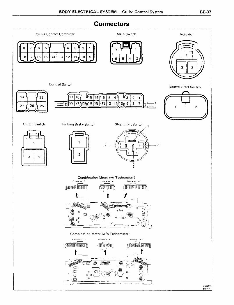
Connectors
Cruise Control Computer Main Switch Actuator
","'r- -"') r; -",,"'r:[ 1
8
8
7 6 5 3 2 1
~17 ~6 15 14 113 12 11 \,.10 910.- --J... ....J....
Control SwitchNeutral Start Switch
15 14 6 5 4 3 2 1......-+--+-----4-.+--I
19 18 13 12 11 10 9 8 7
CI utch Switch Parking Brake Switch Stop Light Switch 1
2
4 Il--...J....L-I-_ 2
3
Combination Meter (wi Tachometer)Connector "C" Connector "B" Connector"A"
Combination Meter (w/o Tachometer)
Connector "C" Connector "B" Connector "A"
BE0208
BE0210
BE-38 BODY ELECTRICAL SYSTEM - Cruise Control System
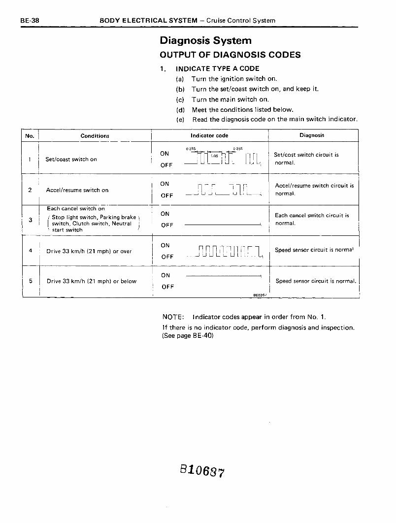
Diagnosis SystemOUTPUT OF DIAGNOSIS CODES
1. INDICATE TYPE A CODE
(a) Turn the ignition switch on.
(b) Turn the set/coast switch on, and keep it.
(c) Turn the main switch on.
(d) Meet the conditions listed below.
(e) Read the diagnosis code on the main switch indicator.
No. Conditions Indicator code Diagnosis
0.255 0255
I ON
~J1JLSet/cost switch circuit is
1 I Set/coast switch onI OFF )
normal.Ii
I ON
~'lJlJLJ1J1JLAccel/resume switch circuit is
2 Accellresume switch on!
IOFF normal.
IEach cancel switch on
( Stop Iight switch, Parking brake )ON Each cancel switch circuit is
3
I
switch, Clutch switch, Neutral OFF () normal.
start switch
I'! ON
_rlJU1JlJ1JlJ1IlJL4 Drive 33 km/h (21 mph) or over Speed sensor circuit is norma'OFF
ON I)
5 Drive 33 km/h (21 mph) or below Speed sensor circuit is normal.OFF
BE0267
NOTE: Indicator codes appear in order from NO.1.
If there is no indicator code, perform diagnosis and inspection.(See page BE -40)
810687
BODY ELECTRICAL SYSTEM - Cruise Control System BE-39
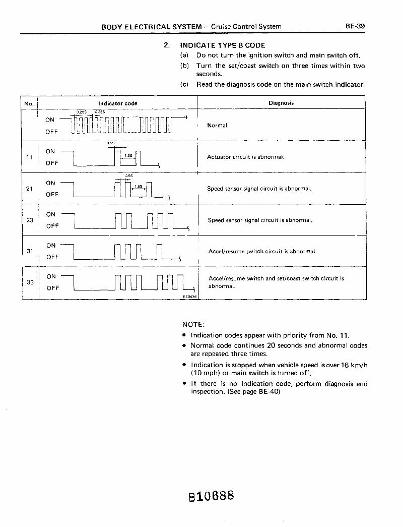
2. INDICATE TYPE B CODE
(a) Do not turn the ignition switch and main switch off.
(b) Turn the set/coast switch on three times within twoseconds.
(c) Read the diagnosis code on the main switch indicator.
No. Indicator code Diagnosis
Normal
05S
ON21
OFF
ON23
OFF
ON31
OFF
ON33
OFF
Actuator circuit is abnormal.
Accel/resume switch and set/coast switch circuit isabnormal.
Speed sensor signal circuit is abnormal.
Accel/resume switch circuit is abnormal.
Speed sensor signal circuit is abnormal.
ON
OFF11
BE0426
NOTE:
• Indication codes appear with priority from No. 11 .
• Normal code continues 20 seconds and abnormal codesare repeated three times.
• Indication is stopped when vehicle speed isover 16 km/h(10 mph) or main switch is turned off.
• If there is no ind ication code, perform diagnosis andinspection. (See page BE-40)
810688

BE-40 BODY ELECTRICAL SYSTEM - Cruise Control System
3. INSPECT DIAGNOSIS CIRCUIT
Turn ignition switch on. I
r---------.l.------., NoIs WIPER fuse normal? r
Yes
Replace fuse.Is operation normal?
~ Yes
Fuse faulty.
NoI--------J. Short circuit in wireness
between fuse and terminal2of main switch.
• Inspect main switch.
MAIN S/W
INSPECT POWER SOURCE
Is there battery voltage between 2 andbody ground?
Yes
INSPECT GROUND CONNECTION
Is there continuity between terminal 3and body ground?
Yes
INSPECT SWITCH OPERATION
Is there battery voltage between term inal6 and body ground with main switchturned on ?
Yes
INSPECT INDICATOR LIGHTOPERATION
Connect terminal 4 to body ground.Does indicator light light with mainswitch turned on ?
Yes
CONTROL S/W
INSPECT GROUND CONNECTION
Is there continu ity between term inal 14and body grou nd ?
Yes
INSPECT SET/COAST SWITCHOPERATION
Is there continuity between terminal 25and body ground with set/coast switchturned on ?
No
No
No
No
No
No
Open circuit in wire harness betweenWIPER fuse and terminal 2 of mainswitch.
• Open circuit in wire harness betweenterminal 3 of main switch and body ground.
• Body ground faulty.
• Short circuit in wire harness betweenterminal 6 of main switch and terminal10 of computer.
• Inspect main switch.
Inspect main switch.
• Open circuit in wire harness betweenterminal 14 and body ground.
• Body ground faulty.
Inspect control switch.
I
I
IYes
CONTINUED ON NEXT PAGE 810689
BODY ELECTRICAL SYSTEM - Cruise Control System BE-41
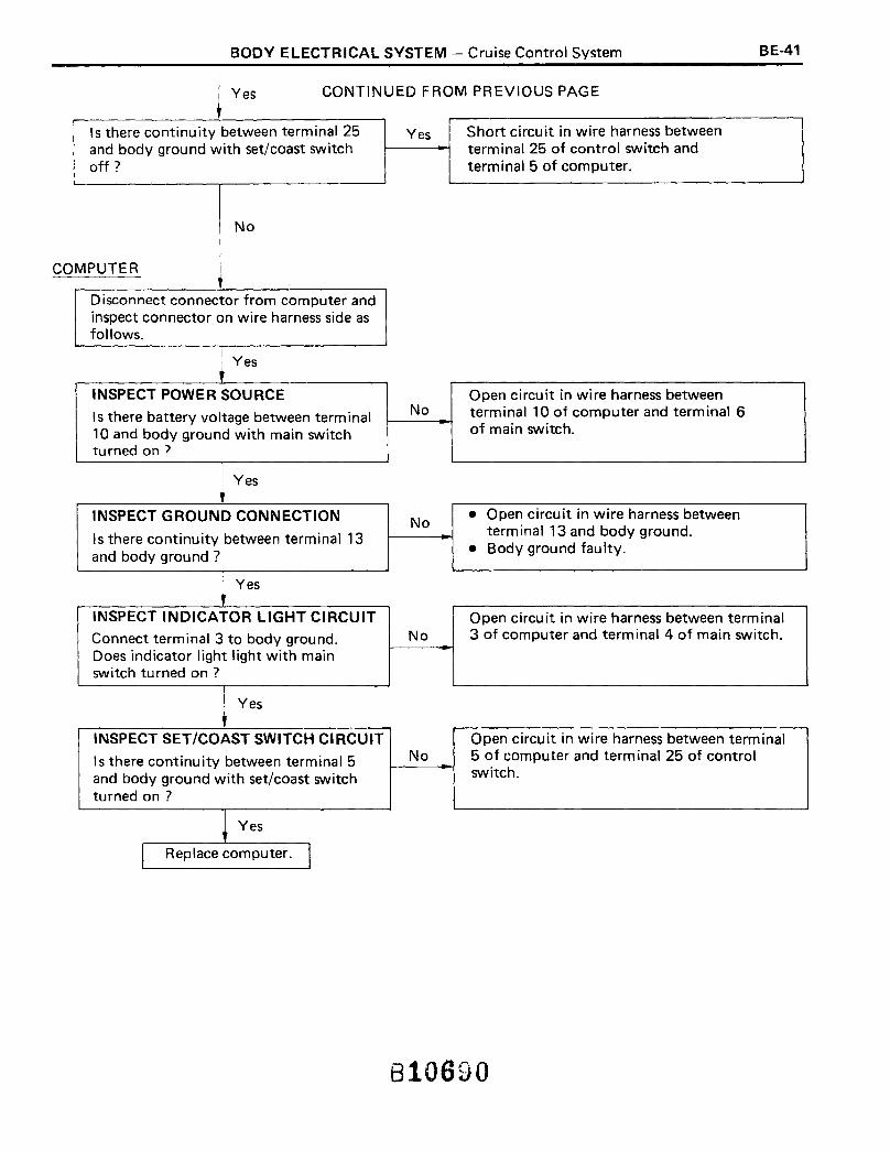
~ Yes CONTINUED FROM PREVIOUS PAGE
Is there continuity between terminal 25and body ground with set/coast switchoff?
No
COMPUTER
Disconnect connector from computer andinspect connector on wire harness side asfollows.
Yes
INSPECT POWER SOURCE
Is there battery voltage between terminal10 and body ground with main switchturned on ?
Yes
INSPECT GROUND CONNECTION
Is there continuity between terminal 13and body ground?
Yes
INSPECT INDICATOR LIGHT CIRCUIT
Connect terminal 3 to body ground.Does indicator light light with mainswitch turned on ?
Yes
INSPECT SET/COAST SWITCH CIRCUIT
Is there continuity between terminal 5and body ground with set/coast switchturned on ?
Yes
I Replace computer. I
Yes
No
No
No
No
Short circuit in wire harness betweenterminal 25 of control switch andterminal 5 of computer.
Open circuit in wire harness betweenterminal 10 of computer and terminal 6of main switch.
• Open circuit in wire harness betweenterminal 13 and body ground.
• Body ground faulty.
Open circuit in wire harness between terminal3 of computer and term inal 4 of main switch.
Open circuit in wire harness between terminal5 of computer and terminal 25 of controlswitch.
810690

BE-42 BODY ELECTRICAL SYSTEM - Cruise Control System
TROUBLESHOOTING
Symptom Inspection Area Section
Cruise control cannot be set. (a) Inspect type A code. No.1 NO A
No.2 NO B
No. 3 NO C
No.4 NO D
No.5 NO D
(b) Inspect type B code. 11 E
21 D
23 F
31 B
33 A and B
(c) All codes are normal.ReplaceComputer
Vehicle speed does not reduce when coast switch OK F
turned on.Inspect No. 1 of type A code.
NO A
Vehicle does not accelerate when accel switchInspect No.2 of type A code.
OK F
turned on. NO B
Vehicle speed does not return to memorized speedInspect No.2 of type A code.
OK F
when resume switch turned on. NO B
Set speed deviates on high side. OK F
Set speed deviates on low side.Inspect No. 1 of type A code.
NO A
Vehicle speed fluctuates when set switch turned Inspect No. 1 of type A code.OK F
on. NO A
Setting speed does not cancel when brake pedalInspect No.3 of type A code.
OK F
depressed. NO C
Setting speed does not cancel when parking brakeInspect No.3 of type A code.
OK Fpulled. NO C
Setting speed does not cancel when clutch pedalInspect No.3 of type A code.
OK Fdepressed (MIT only). NO C
Setting speed does not cancel when shifted toInspect No.3 of type A code.
OK F"N" range (A/T only). NO C
Speed can be set below 33 km/h (21 mph). Inspect No.4 of type A code.OK FNO D
Cruise control will not disengage even below OK F33 km/h (21 mph).
Inspect No.5 of type A code. NO D
810691

BODY ELECTRICAL SYSTEM - Cruise Control System BE-43
I~ INSPECTION OF SET/COAST SWITCH CIRCUIT
COMPUTER
INSPECT SET/COAST SWITCH CIRCUIT • Short circuit in wire harness between
Disconnect connector from computer. Yes terminal 5 of computer and terminal 25
Is there continuity between terminal 5 of control switch.
and body ground with set/coast switch • Inspect control switch.
turned off?
~ No
\ Replace computer.
[B] INSPECTION OF ACCEL/RESUME SWITCH CIRCUIT
CONTROL S/W
No
INSPECT ACCEL!RESUME SWITCH • Short circuit in wire harness betweenOPERATION Yes terminal 23 of control switch and terminal
Is there continu ity between term inal 23 17 of computer.
and body ground with accel/resume • Inspect control switch.
switch turned off ?I,
Is there continuity between terminal 23 No Inspect control switch.and body ground with accel/resumeswitch turned on ?
I
Yes
COMPUTER
INSPECT ACCEL/RESUME SWITCHCIRCUIT
Disconnect connector from computer.Is there continuity between terminal 17and body ground with accel/resume switchturned on ?
No
Open circuit in wire harness between terminal17 of computer and terminal 23 of controlswitch.
~ Yes
I Replace computer. I
810692
BE-44 BODY ELECTRICAL SYSTEM - Cruise Control System
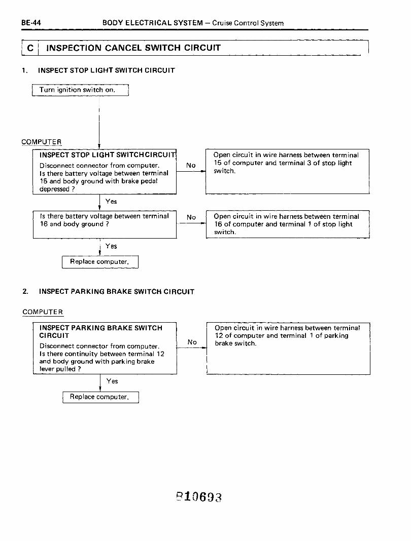
@J INSPECTION CANCEL SWITCH CIRCUIT
1. INSPECT STOP LIGHT SWITCH CIRCUIT
Turn ignition switch on.
COMPUTER
INSPECT STOP LIGHT SWITCH CIRCUIT
Disconnect connector from computer. NoIs there battery voltage between terminal15 and body ground with brake pedaldepressed?
Yes
Open circuit in wire harness between terminal15 of computer and term inal 3 of stop lightswitch.
Is there battery voltage between terminal16 and body ground?
Yes
I Replace computer. I
No Open circuit in wire harness between terminal16 of computer and terminal 1 of stop lightswitch.
2. INSPECT PARKING BRAKE SWITCH CIRCUIT
COMPUTER
INSPECT PARKING BRAKE SWITCHCIRCUIT
Disconnect connector from computer.Is there continuity between terminal 12and body ground with parking brakelever pu lied ?
~ Yes
I Replace computer. I
No
Open circuit in wire harness between terminal12 of computer and terminal 1 of parkingbrake switch.
810693
BODY ELECTRICAL SYSTEM - Cruise Control System
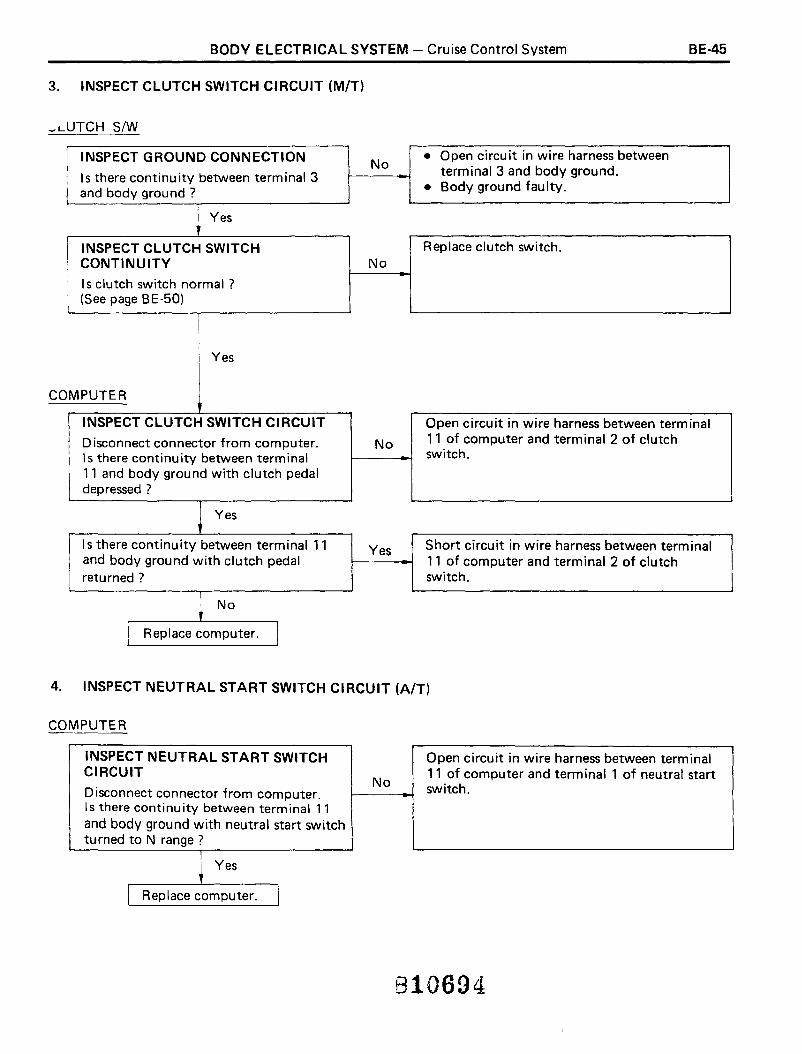
3. INSPECT CLUTCH SWITCH CIRCUIT (MIT)
.... L..UTCH S/W
BE-45
INSPECT GROUND CONNECTION No• Open circuit in wire harness between
Is there continuity between terminal 3 terminal 3 and body ground.
and body ground ? • Body ground faulty.
Yes
INSPECT CLUTCH SWITCH Replace clutch switch.CONTINUITY No
Is clutch switch normal?(See page BE-50)
Yes
COMPUTER
INSPECT CLUTCH SWITCH CIRCUIT
Disconnect connector from computer.Is there continuity between terminal11 and body ground with clutch pedaldepressed?
Yes
Is there continuity between terminal 11and body ground with clutch pedalreturned?
No
I Replace computer. I
No
Yes
Open circuit in wire harness between terminal11 of computer and terminal 2 of clutchswitch.
Short circuit in wire harness between terminal11 of computer and terminal 2 of clutchswitch.
4. INSPECT NEUTRAL START SWITCH CIRCUIT (A/T)
COMPUTER
INSPECT NEUTRAL START SWITCH Open circuit in wire harness between terminalCIRCUIT
No11 of computer and terminal 1 of neutral start
Disconnect connector from computer. switch.
Is there continuity between terminal 11and body ground with neutral start switchturned to N range?
~ Yes
r Replace computer. I
810694

BE-46 BODY ELECTRICAL SYSTEM - Cruise Control System
~I INSPECTION OF SPEED SENSOR CIRCUIT
SPEED SENSOR
INSPECT GROUND CONNECTION
Disconnect combination meter.Is there continuity between terminal B-7of wire harness side and body ground?
Yes
INSPECT SPEED SENSOR OPERATION
Is speed sensor normal?(See page BE-51)
Yes
COMPUTER
INSPECT SPEED SENSOR CIRCUIT
Disconnect connector from computerand combination meter.Is there continuity between terminal 7and body ground?
No
Is there continuity between terminal 7of computer and term inal B-4 ofcombination meter?
Yes
\ Replace computer. I
No
No
Yes
No
• Open circuit in wire harness betweenterminal B-7 of combination meter andbody ground.
• Body ground faulty.
Replace speed sensor.
Short circuit in wire harness between terminal7 of computer and terminal 8-4 of combinationmeter.
Open circuit in wire harness between terminal7 of computer and terminal B-4 of combinationmeter.
810695

BODY ELECTRICAL SYSTEM - Cruise Control System BE-47
[E] INSPECTION OF ACTUATOR OPERATION
ACTUATOR
INSPECT ACTUATOR OPERATION Replace actuator.
Remove actuator. No
Is actuator normal?(See page BE-51)
Yes
I Replace computer. I
o INSPECTION OF ACTUATOR CIRCUIT
ACTUATOR
INSPECT ACTUATOR OPERATION Replace actuator.
Remove actuator. No
Is actuator normal?(See page BE-51)
T
,INSPECT RELEASE VALVE CIRCUIT Short circuit in wire harness between terminal
Yes 2 of computer and terminal 3 of actuator.Disconnect actuator.Is there continuity between terminal 2and body grou nd ?
No
Yes
OP LIGHT S/W
INSPECT STOP LIGHT SWITCH Replace stop light switch.OPERATION No
Is stop light switch normal?(See page BE-50)
Yes
MPUTER
Disconnect connector from computer andinspect connector on wire harness asfollows.
\
ST
CO
, CONTINUED FROM PREVIOUS PAGE

BE-48 BODY ELECTRICAL SYSTEM - Cruise Control System
~ No CONTINUED FROM PREVIOUS PAGE
Is resistance value about 68 n betweenterminals 2 and 14 with brake pedalreturned?
~ Yes
INSPECT CONTROL VALVE CIRCUIT
Is resistance valve about 30 n betweenterminals 4 and 14 ?
~ Yes
r Replace computer. I
No
No-
• Open circuit in wire harness betweenterminal 2 of computer and terminal 3of actuator.
• Open circuit in wire harness betweenterm inal 14 of computer and term inal 1of actuator.
Open or short circuit in wire harness betweenterminal 4 of computer and terminal 2 ofactuator.
810697

BODY ELECTRICAL SYSTEM - Cruise Control System
Cruise Control Computer CircuitINSPECTION OF COMPUTER CIRCUIT
BE-49
Disconnect the computer and inspect the connector on thewire harness side as shown in the chart below.
TerminalConnection or
Check item Tester connection ConditionVoltage or
Measure item Resistance value---
2i Stop Light Switch
Resistance 2 - 14 Brake pedal returned About 6an.and Release Valve
I
Turn ignition switch andBattery voltage
main switch on3 Main Switch Voltage 3 - Body Ground
ITurn ignition switch and/or
No voltageI main switch off
4 I Control Valve Resistance i 4 - 14\
- About 30n.
1
15 - Body GroundTurn set/coast switch on Continuity
5] Control/Switch
Continuity(set/coast)
I Turn set/coast switch off No continuity
6 00 relay - I -i
- -i
i I 1 pulse each7 I Speed Sensor Continuity 7 - Body Ground Vehicle moving slowly
40 cm (15.75 in.):I
I Turn ignition switch andI
I main switch onBattery vo Itage
10 Main Switch I Voltage I 10 - Body GroundI
Turn ignition switch and/orNo voltage
I main switch off
Clutch pedal depressed orContinuity
Clutch Switch (M/T) shifted into liN" range
11 or Neutral Start Continuity 11 - Body Ground Clutch pedal returned orSwitch (A/T)
shifted into only range except No continuityI liN" rangeI
IParking Brake SwitchParking brake pulled No voltage
12 Voltage 12 - Body GroundParking brake returned Battery voltage
13 Body Ground Continuity 113 - Body Ground - Continuity
14 I Release Valve andIControl Valve - - - -
Brake pedal depressed Battery voltage15 Stop Light Switch Voltage 15 - Body Ground
Brake pedal returned No voltage
16 ' STOP Fuse Voltage 16 - Body Ground - Battery voltage
Control Switch Turn accel/resume switch on Continuity17
(accel/resume)Continuity 17 - Body Ground
Turn accel/resume switch off No continuity
81060:
BE-50 BODY ELECTRICAL SYSTEM - Cruise Control System
4
Continuity
BE0574
No Continuity
BE0574
BE0336
[5' 1,. ~
1
"" III
rnH-3-2
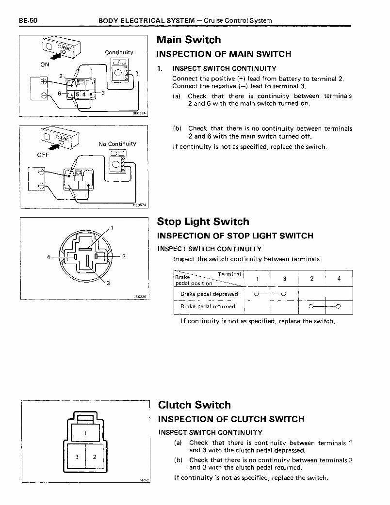
Main SwitchINSPECTION OF MAIN SWITCH
1. INSPECT SWITCH CONTINUITY
Connect the positive (+) lead from battery to terminal 2.Connect the negative (-) lead to terminal 3.
(a) Check that there is continuity between terminals2 and 6 with the main switch turned on.
(b) Check that there is no continuity between terminals2 and 6 with the main switch turned off.
If continu ity is not as specified, replace the switch.
Stop Light SwitchINSPECTION OF STOP LIGHT SWITCH
INSPECT SWITCH CONTINUITY
Inspect the switch continuity between terminals.
~ 1 3 2 4pedal position
Brake pedal depressed
Brake pedal returned
If continuity is not as specified, replace the switch.
Clutch SwitchINSPECTION OF CLUTCH SWITCH
INSPECT SWITCH CONTINUITY
(a) Check that there is continu ity between term inals "l
and 3 with the clutch pedal depressed.
(b) Check that there is no continuity between terminals 2and 3 with the clutch pedal returned.
I f continuity is not as specified, replace the switch.
BODY ELECTRICAL SYSTEM - Cruise Control System
Control Switch(See page BE-11)
Neutral Start Switch(See page AT-92)
Parking Brake Switch(See page BE-29)
BE-51
Speed Sensor(See page BE-37)
INSPECTION OF SPEED SENSORINSPECT SENSOR CONTINUITY
Check that there is continu ity between term inals 4 of connector liB" and terminal 7 of connector liB" four timesper each revolution of the shaft.
If continu ity is not as specified, replace the sensor.
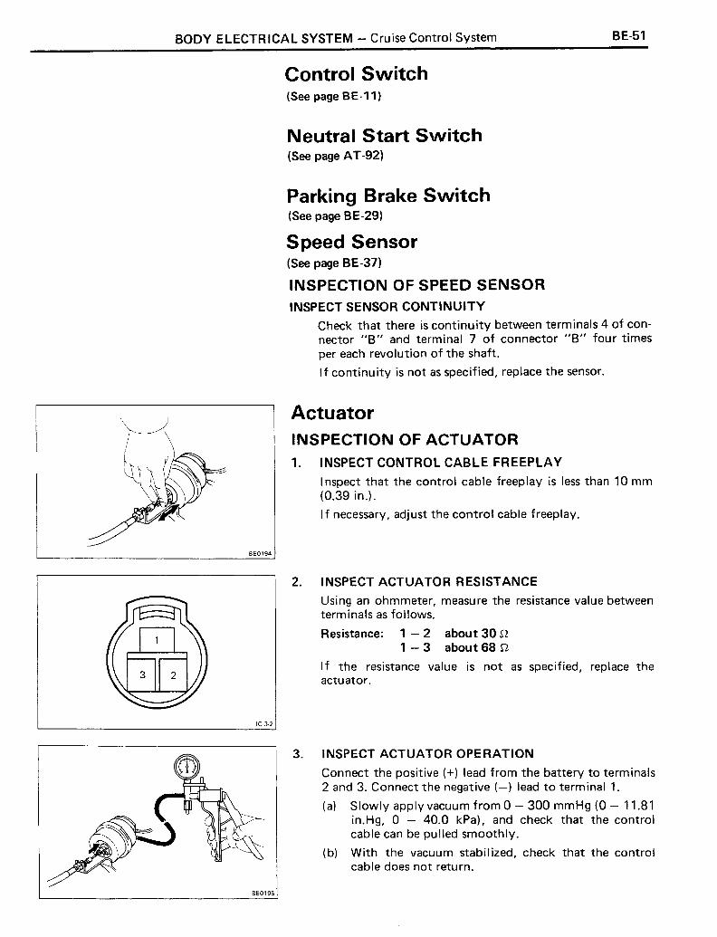
ActuatorINSPECTION OF ACTUATOR
1. INSPECT CONTROL CABLE FREEPLAY
Inspect that the control cable freeplay is less than 10 mm(0.39 in.).
If necessary, adjust the control cable freeplay.
BE0194
2. INSPECT ACTUATOR RESISTANCE
Using an ohmmeter, measure the resistance value betweenterm inals as follows.
Resistance: 1 - 2 about 30 n1 - 3 about 68 n
If the resistance value is not as specified, replace theactuator.
IC·3·2
3. INSPECT ACTUATOR OPERATION
Connect the positive (+) lead from the battery to terminals2 and 3. Connect the negative (-) lead to terminal 1.
(a) Slowly apply vacuum from 0 - 300 mmHg (0 - 11.81in.Hg, 0 - 40.0 kPa), and check that the controlcable can be pulled smoothly.
(b) With the vacuum stabilized, check that the controlcable does not return.
BE0195

BE-52 BODY ELECTRICAL SYSTEM - Cruise Control System
(c) Disconnect terminal 2 or 3 and check that the controlcable returns to its original position and the vacuumreturns to 0 mmHg (0 in.Hg, 0 kPa).
If operation is not as specified, replace the actuator.
810701

BODY ELECTRICAL SYSTEM - Power Window BE-53
POWER WINDOWPower Window Master SwitchINSPECTION OF MASTER SWITCH
INSPECT SWITCH CONTINUITY
Inspect the switch continuity between terminals.
Window Switch Front· Left Front· Right
G-7-2
If continuity is not as specified, replace the switch.
Power Window Door SwitchINSPECTION OF DOOR SWITCH
INSPECT SWITCH CONTINUITY
Inspect the switch continuity between terminals.
~Switc 1 2 3 4 5position
UP
OFF
D -0DOWN 0 -0G-5-2 If continuity is not as specified, replace the switch.
2. INSPECT RELAY OPERATION
(a) Apply battery voltage across terminals 1 and 3.
(b) Check that there is continuity between terminals 2 and4.
(c) Check that there is no continuity between terminals2 and 3.
If operation is not as specified, replace the relay.
1 . INSPECT RELAY CONTINUITY
(a) Check that there is continuity between terminals 1 and3.
(b) Check that there is no continuity between terminals1 and 4.
(c) Check that there is no continuity between terminals2 and 4.
If continuity is not as specified, replace the relay.
Power Main RelayINSPECTION OF MAIN RELAY
BE0010
Continuity
L:"KJo
No Continuity
~
Continuity
C1[J
BE-54 BODY ELECTRICAL SYSTEM - Power Window
ID-2-2
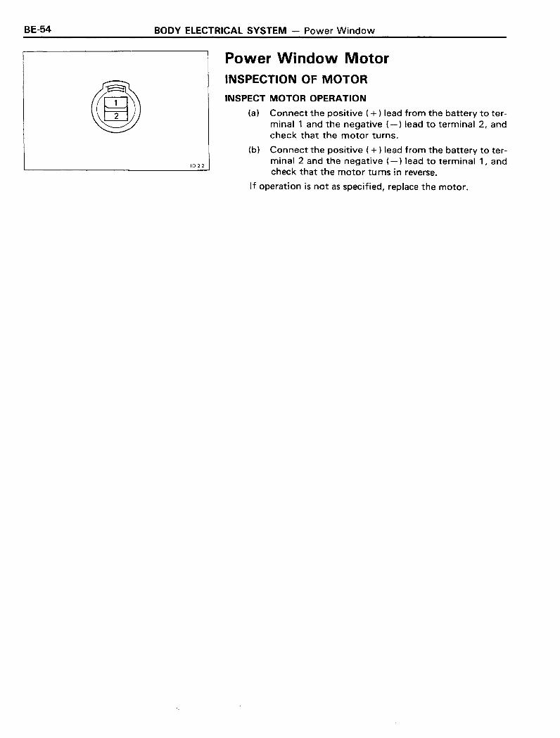
Power Window MotorINSPECTION OF MOTOR
INSPECT MOTOR OPERATION
(a) Connect the positive ( + ) lead from the battery to terminal 1 and the negative (-) lead to terminal 2, andcheck that the motor turns.
(b) Connect the positive ( + ) lead from the battery to terminal 2 and the negative (-) lead to terminal 1, andcheck that the motor turns in reverse.
If operation is not as specified, replace the motor.

BODY ELECTRICAL SYSTEM - Back Door Power Window BE-55
BACK DOOR POWER WINDOW
Wiring Diagram
Rear WiperRetractionDetectionSwitch(WiperretractedOFF)
OFF Rear Wiper andWindow t-=-0~N-+--+-~-+-+-~Washer SwitchLimit ....W_A_S_H~.-... ..............I...-~
Switch(Fully closed:
DoorLockDetectionSwitch
Circuit Breaker
BackDoorControlSwitch
U 0PowerWindowRegulatorSwitch
Power WindowMotor
Power Window and Wiper Relay
ENGINE Fuse
30AFusibleLink
BACKDOORWarningLight
Ignition Switch
TI Battery
-l.-
I
60A
.....---. ,....6 5 41, ~3 2 1
13 12 11J 10Jl9 8 7~
Power Window and Wiper Relay
Power Window Regulator Switch
~~~ m @~
Door Lock Detection Cover Top Switch Power Window MotorSwitch
rE5J rmBack Door Unlock Rear Wiper Retraction Back Door ControlWarning Switch Detection Switch Switch
BE0216
BE-56 BODY ELECTRICAL SYSTEM - Back Door Power Window
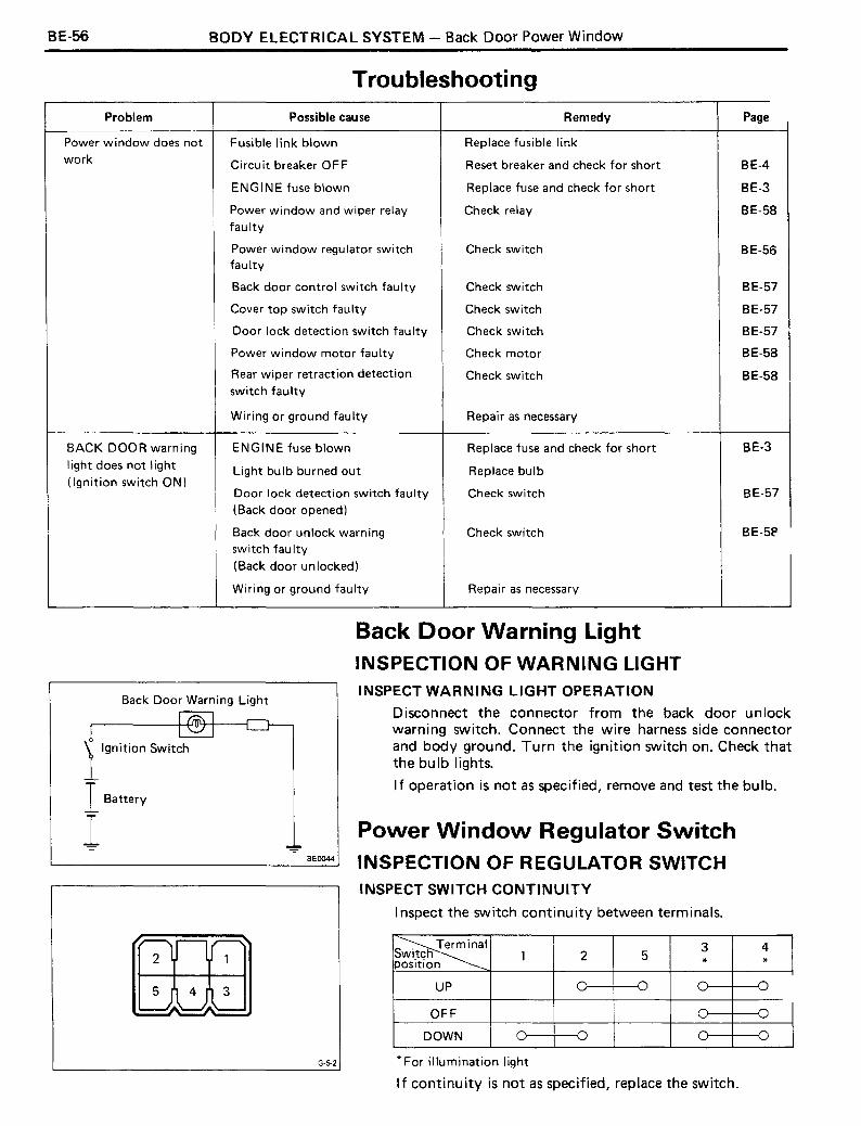
Troubleshooting
Problem Possible cause Remedy Page
Power window does not Fusible link blown Replace fusible linkwork Circuit breaker OFF Reset breaker and check for short BE-4
ENGINE fuse blown Replace fuse and check for short BE-3
Power window and wiper relay Check relay BE-58faulty
Power window regulator switch Check switch BE-56faulty
Back door control switch faulty Check switch BE-57
Cover top switch fau Ity Check switch BE-57
Door lock detection switch faulty Check switch BE-57
Power wi ndow motor fau Ity Check motor BE-58
Rear wiper retraction detection Check switch BE-58switch faulty
Wiring or ground faulty Repair as necessary
BACK DOOR warning ENGINE fuse blown Replace fuse and check for short BE-3
Iight does not light Light bulb burned out Replace bulb(Ignition switch ON)
Door lock detection switch faulty Check switch BE-57(Back door opened)
Back door unlock warning Check switch BE-5Pswitch faulty
(Back door unlocked)
Wiring or ground faulty Repair as necessary
Back Door Warning Light
l,gnition Switch
I Battery
1BE0044
Back Door Warning LightINSPECTION OF WARNING LIGHTINSPECT WARNING LIGHT OPERATION
Disconnect the connector from the back door unlockwarning switch. Connect the wire harness side connectorand body ground. Turn the ignition switch on. Check thatthe bulb lights.
If operation is not as specified, remove and test the bulb.
Power Window Regulator SwitchINSPECTION OF REGULATOR SWITCHINSPECT SWITCH CONTINUITY
Inspect the switch continu ity between terminals.
~~3 4wltcn 1 2 5
position * *
UP
OFF
DOWN
G·5-2 * For illumination light'---------------------'If continu ity is not as specified, replace the switch.

BODY ELECTRICAL SYSTEM - Back Door Power Window BE-57
IH-6-2
15-3-2
H-3-2
Back Door Control SwitchINSPECTION OF CONTROL SWITCH
INSPECT SWITCH CONTINUITY
Inspect the switch continuity between terminals.
~Switch 1 2 3position
UP (Left)
OFF
DOWN (Right) -0
If continu ity is not as specified, replace the switch.
Door Lock Detection SwitchINSPECTION OF LOCK DETECTION SWITCH
INSPECT SWITCH CONTINUITY
Inspect the switch continuity between terminals.
~~ 1 2 3position
Unlock(Back door opened)
Locked(Back door closed)
NOTE: When the locked position, lock the left side backdoor lock assembly by push into the screwdriver or such tothe lock assembly.
If continuity is not as specified, replace the switch.
Cover Top SwitchINSPECTION OF COVER TOP SWITCH
INSPECT SWITCH CONTINUITY
Inspect the switch continuity between terminals.
~~ 1 2 3position
Free
Pushed
If continu ity is not as specified, replace the switch.
BE-58 BODY ELECTRICAL SYSTEM - Back Door Power Window
IC-2-2
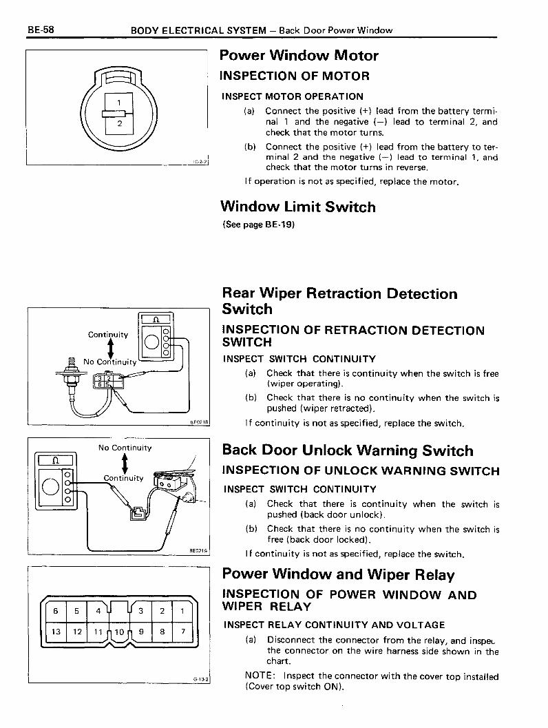
Power Window MotorINSPECTION OF MOTOR
INSPECT MOTOR OPERATION
(a) Connect the positive (+) lead from the battery terminal 1 and the negative (-) lead to terminal 2, andcheck that the motor tu rns.
(b) Connect the positive (+) lead from the battery to terminal 2 and the negative (-) lead to terminal 1, andcheck that the motor turns in reverse.
If operation is not as specified, replace the motor.
Window Limit Switch(See page BE-19)
Rear Wiper Retraction DetectionSwitchINSPECTION OF RETRACTION DETECTIONSWITCHINSPECT SWITCH CONTINUITY
(a) Check that there is continuity when the switch is free(wiper operating).
(b) Check that there is no continuity when the switch ispushed (wiper retracted).
'-- .......;B;;.::.EO:..;;..21....;.J8 If continuity is not as specified, replace the switch.
nNo Continuity
t(')+.I~_......Continuity
BE0219
Back Door Unlock Warning SwitchINSPECTION OF UNLOCK WARNING SWITCH
INSPECT SWITCH CONTINUITY
(a) Check that there is continuity when the switch ispushed (back door unlock).
(b) Check that there is no continuity when the switch isfree (back door locked).
If continuity is not as specified, replace the switch.
/ ~
~nr6 5 4 3 2 1
13 12 11..;~'l 9 8 7
G·13-2
Power Window and Wiper RelayINSPECTION OF POWER WINDOW ANDWIPER RELAY
INSPECT RELAY CONTINUITY AND VOLTAGE
(a) Disconnect the connector from the relay, and inspeLthe connector on the wire harness side shown in thechart.
NOTE: Inspect the connector with the cover top installed(Cover top switch ON).
eODY ELECTRICAL SYSTEM - Back Door Power Window BE-59
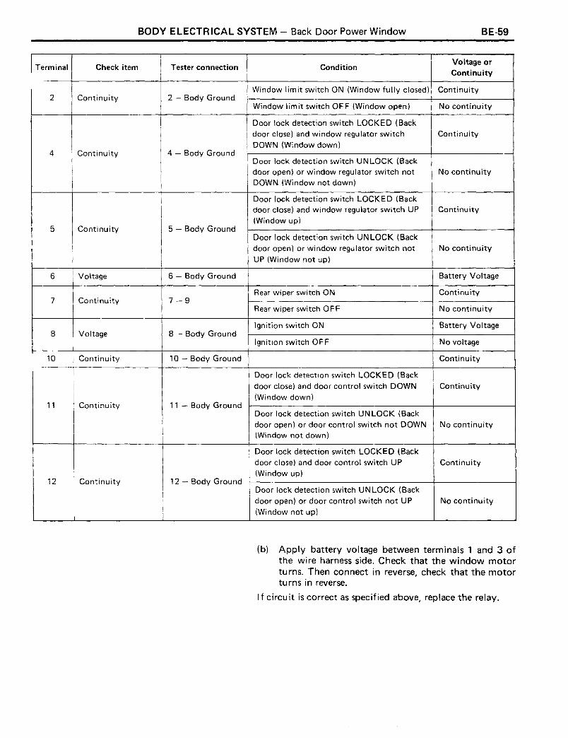
ITerminal Check item Tester connection ConditionVoltage orContinuity
Window limit switch ON (Window fully closed) Continuity2 Continuity 2 - Body Ground
Window limit switch OFF (Window open) No continuity
Door lock detection switch LOCKED (Backdoor close) and window regulator switch ContinuityDOWN (Window down)
4 Continuity 4 - Body GroundDoor lock detection switch UN LOCK (Backdoor open) or window regulator switch not No continuityDOWN (Window not down)
Door lock detection switch LOCKED (Backdoor close) and window regulator switch UP Continuity(Window up)
5 Continuity 5 - Body GroundDoor lock detection switch UN LOCK (Backdoor open) or window regulator switch not No continuity
UP (Window not up)
6 Voltage 6 - Body Ground Battery Voltage
Rear wiper switch ON Continuity7 Continuity 7-9
Rear wiper switch OFF No continuity
Ignition switch ON Battery Voltage8 Voltage 8 - Body Ground
Ignition switch OF F No voltage
10 Continuity 10 - Body Ground Continuity
Door lock detection switch LOCKED (Back
door close) and door control switch DOWN Continuity(Window down)
11 Continuity 11 - Body GroundDoor lock detection switch UNLOCK (Backdoor open) or door control switch not DOWN No continuity(Window not down)
Door lock detection switch LOCKED (Backdoor close) and door control switch UP Continuity(Window up)
12 Continuity 12 - Body GroundDoor lock detection switch UNLOCK (Backdoor open) or door control switch not UP No continuity(Window not up)
(b) Apply battery voltage between terminals 1 and 3 ofthe wire harness side. Check that the window motorturns. Then connect in reverse, check that the motorturns in reverse.
If circu it is correct as specified above, replace the relay.

BE-GO BODY ELECTRICAL SYSTEM - Radio, Stereo Tape Player and Motor Antenna
RADIO, STEREO TAPE PLAYERAND MOTOR ANTENNA
TroubleshootingDESCRIPTION OF SYMBOLS
Do
©
Inspection
Check or replace part
Test by operating radio
TEST 1
1. DEAD RADIO AND TAPE PLAYER
(a) No power to radio or tape player, or power but nosound.
Possible causes:
• Blown C IG fuse
• Short circuit or broken wire in power source wireharness
• Loose connectors behind radio and tape playe~
• Loose speaker connector
• Defective speaker
• Broken wire in speaker wire harness
• Improperly installed radio or tape player
• Defective radio or tape player
Blows again
Short
OK
Does not blow
No short Replace radio and tapeplayer.
Inspect and repair wire harnessfor radio and tape player.
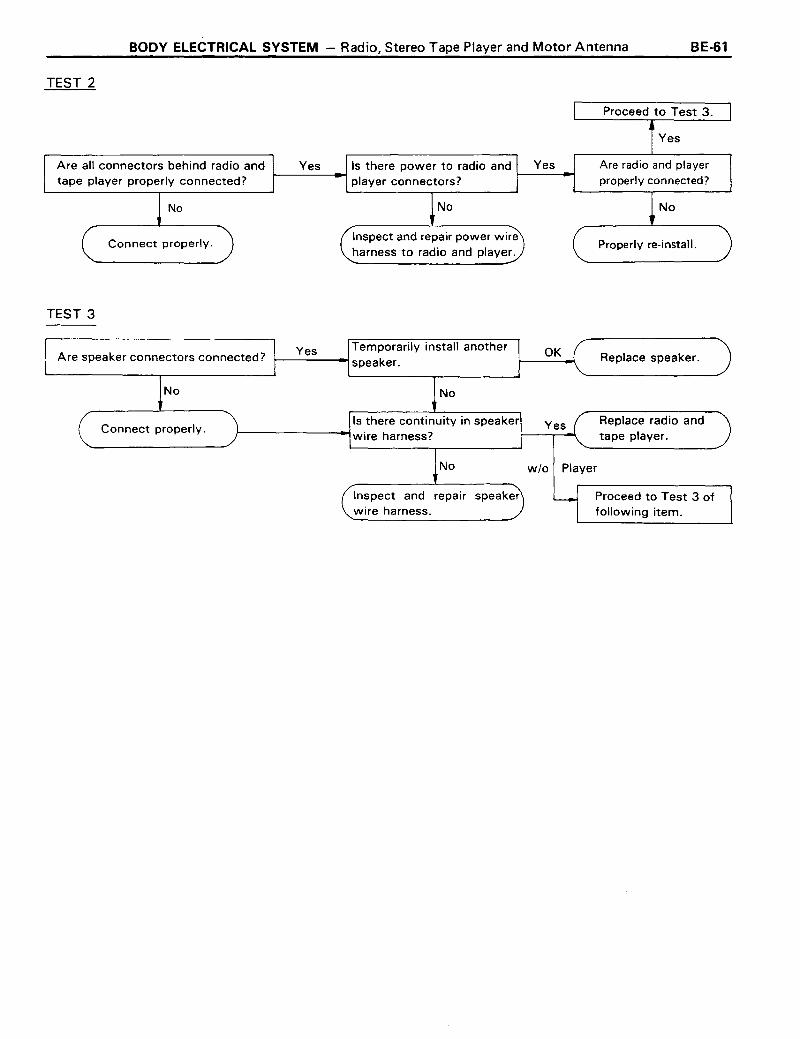
TEST 2
BODY ELECTRICAL SYSTEM - Radio, Stereo Tape Player and Motor Antenna BE-51
YesAre all connectors behind radio andtape player properly connected?
No
Connect properly.
TEST 3
Is there power to radio and1------..1 1----......
player connectors?
No
Inspect and repair power wireharness to radio and player.
Proceed to Test 3.
Yes
Are radio and playerproperly connected?
No
Properly re-install.
Are speaker connectors connected?
No
Connect properly.
Yes Temporarily install anotherspeaker.
No
Is there continuity in speakerwire harness?
No
OK
wlo Player
Replace speaker.
Replace radio andtape player.
Inspect and repair speakerwire harness.
Proceed to Test 3 offollowing item.

BE-62
TEST 1
BODY ELECTRICAL SYSTEM - Radio, Stereo Tape Player and Motor Antenna
(b) Tape player okay but no sound from AM and FM oreither one.
Possible causes:
• Antenna disconnected
• Antenna plug not properly connected
• Defective antenna
• Defective antenna cable
• Defective radio or tape player
• Blown HAZ-HORN fuse
• Short circuit or broken wire in wire harness for backup power source
Is radio electronic searchtype?
TEST 2
Yes Is either AM or FM okay?
No
~__O_K -I Proceed to Test 2.
OK Is there back-up power to connectorsCheck HAZ-HORN fuse. ~-----...I behind radio?
No
YesProceed to Test 3.
No
Blown Inspect and repair back-up powerwire harness.
Blows again
Short
Inspect and repair wire harnessfor back-up power source.
OK
OK Replace radio.
NOTE: Back-up power refers to the storage voltage Tl.ll
preset tuning. This is applied even when the ignition switchis OFF.
BODY ELECTRICAL SYSTEM - Radio, Stereo Tape Player and Motor Antenna BE-53
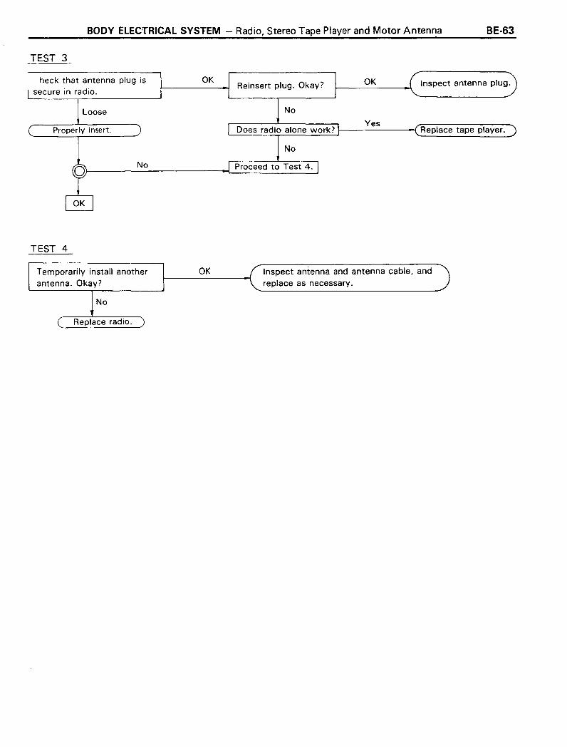
TEST 3
Inspect antenna plug.OK
Yes'-- --.- ----"I------------i Replace tape player.
OK
No
Loose
Properly insert.
heck that antenna plug issecure in radio.
TEST 4
Temporarily install anotherantenna. Okay?
OK Inspect antenna and antenna cable, andreplace as necessary.
~ No
( Replace radio.
BE-54
TEST 1
BODY ELECTRICAL SYSTEM - Radio, Stereo Tape Player and Motor Antenna
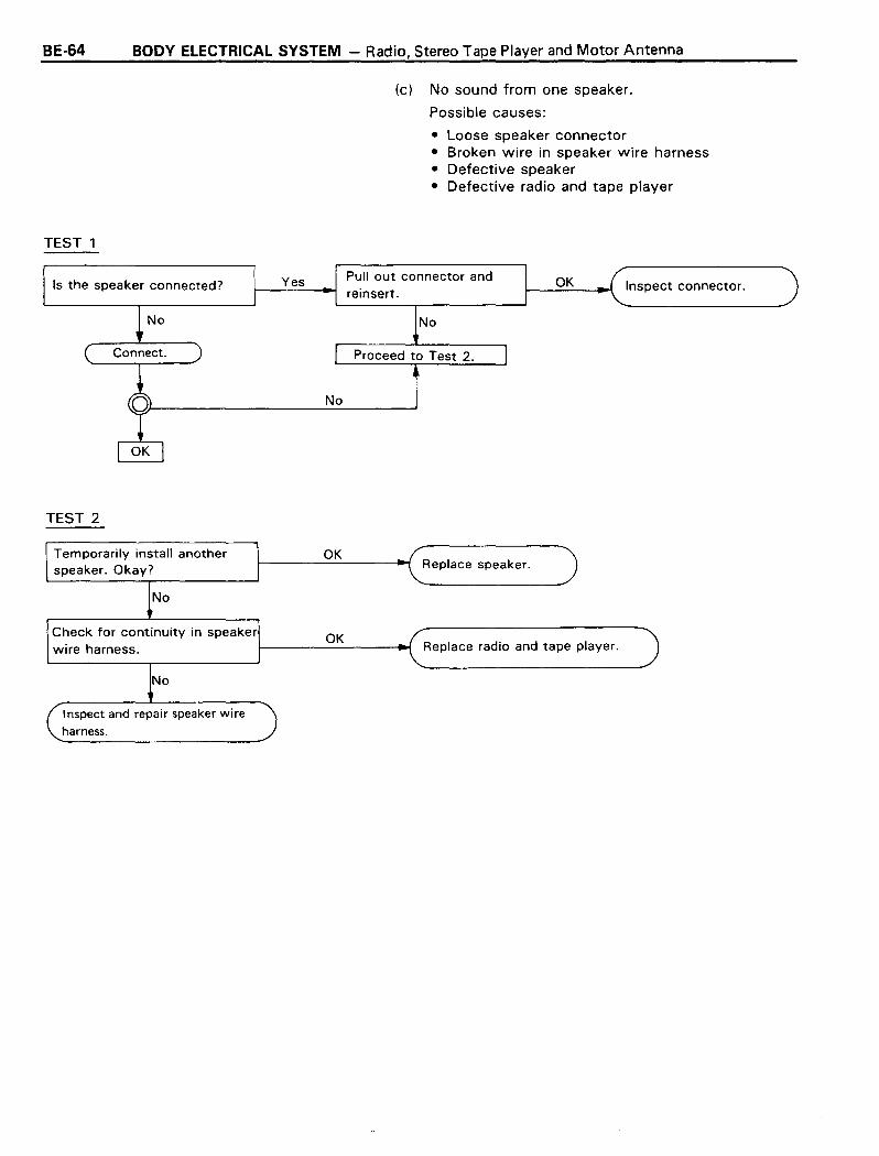
(c) No sound from one speaker.
Possible causes:
• Loose speaker connector• Broken wire in speaker wire harness• Defective speaker• Defective radio and tape player
Is the speaker connected?
TEST 2
Yes Pull out connector andreinsert.
No
Inspect connector.
Temporarily install anotherspeaker. Okay?
No
Check for continuity in speakerwire harness.
Inspect and repair speaker wireharness.
OK
OK
Replace speaker.
Replace radio and tape player.

TEST
BODY ELECTRICAL SYSTEM - Radio, Stereo Tape Player and Motor Antenna
2. FAINT RECEPTION
Possible causes:
• Maladjusted antenna trimmer• Defective antenna cable• Defective speaker• Defective radio
BE-55
Are both reception and static faintwith antenna fully lengthened?
No
Adjust AM antenna trimmer.(See illustration.)
Temporarily install anotherantenna. Okay?
No
Replace radio.
OK
emporarily install another speaker ~--=-_--I Replace speaker.Okay?
No
Replace radio.
OK
Inspect antenna and cable and repairas necessary.
NOTE: Adjustment of antenna trimmer.
(1) Fully lengthen the antenna.
(2) With the volume and tone at maximum, turn the dialto around 1,400 kHz where there is no reception.
(3) Adjust the trimmer to where static is loudest.
BE-66 BODY ELECTRICAL SYSTEM - Radio, Stereo Tape Player and Motor Antenna
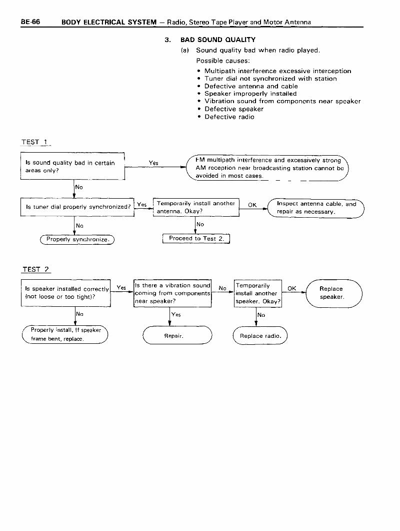
3. BAD SOUND QUALITY
(a) Sound quality bad when radio played.
Possible causes:
• Multipath interference excessive interception• Tuner dial not synchronized with station• Defective antenna and cable• Speaker improperly installed• Vibration sound from components near speaker• Defective speaker• Defective radio
TEST 1
Is sound quality bad in certainareas only?
Yes FM multipath interference and excessively strongAM reception near broadcasting station cannot beavoided in most cases.
Inspect antenna cable, andrepair as necessary.
No
Properly synchronize.
Temporarily install anotherIs tuner dial properly synchronized? I-----t..-l I-__--I~
antenna. Okay?
TEST 2
Yes OK Replacespeaker.
Yes No
Properly install. If speaker
frame bent, replace. Repair. Replace radio.
BODY ELECTRICAL SYSTEM - Radio, Stereo Tape Player and Motor Antenna
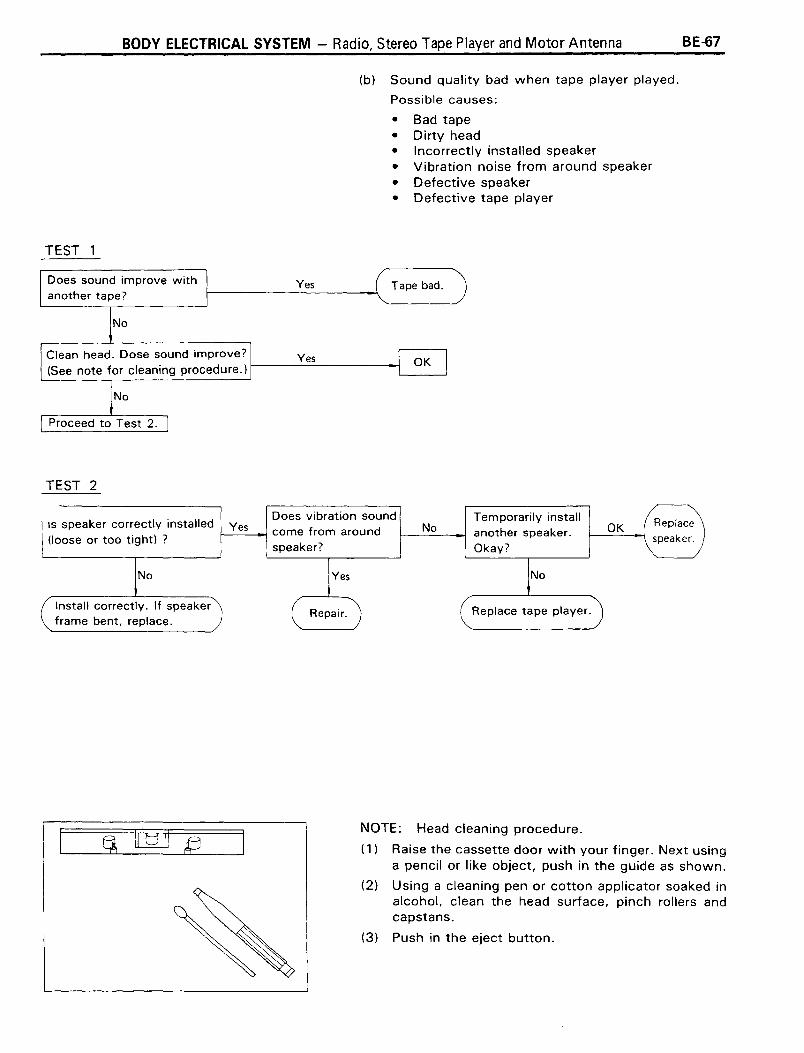
(b) Sound quality bad when tape player played.
Possible causes:
• Bad tape• Dirty head• Incorrectly installed speaker• Vibration noise from around speaker• Defective speaker• Defective tape player
TEST 1
BE-57
Does sound improve withanother tape?
TEST 2
Yes
Yes
Tape bad.
IS speaker correctly installed Yes(loose or too tight) ?
No
Install correctly. If speakerframe bent, replace.
Does vibration soundcome from aroundspeaker?
Yes
Repair.
NoTemporarily installanother speaker.Okay?
Replace tape player.
OK
NOTE: Head cleaning procedure.
(1) Raise the cassette door with your finger. Next usinga pencil or like object, push in the guide as shown.
(2) Using a cleaning pen or cotton applicator soaked inalcohol, clean the head surface, pinch rollers andcapstans.
(3) Push in the eject button.
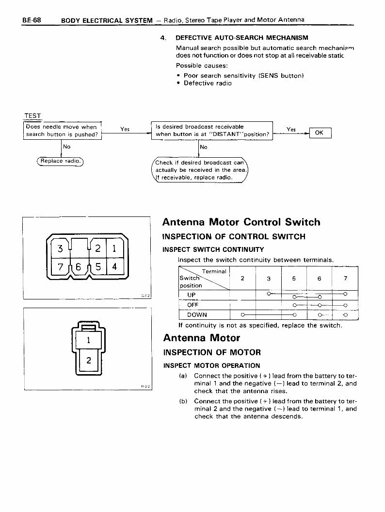
BE-68
TEST
BODY ELECTRICAL SYSTEM - Radio, Stereo Tape Player and Motor Antenna
4. DEFECTIVE AUTO-SEARCH MECHANISM
Manual search possible but automatic search mechani~"l
does not function or does not stop at all receivable static.
Possible causes:
• Poor search sensitivity (SENS button)• Defective radio
Yes
5 4
Does needle move whensearch button is pushed?
2
2
1
Yes
G-72
H-22
Is desired broadcast receivablewhen button is at "DISTANT"position? 1------4-1
'---_---J
No
Check if desired broadcast canactually be received in the area.If receivable, replace radio.
Antenna Motor Control SwitchINSPECTION OF CONTROL SWITCH
INSPECT SWITCH CONTINUITY
Inspect the switch continuity between terminals.
~Switch 2 3 5 6 7position
UP 0 ~
~ ~ '""~ ~
OFF ~
~ ~
DOWN 0
If continuity is not as specified, replace the switch.
Antenna MotorINSPECTION OF MOTOR
INSPECT MOTOR OPERATION
(a) Connect the positive (+ ) lead from the battery to terminal 1 and the negative (-) lead to terminal 2, andcheck that the antenna rises.
(b) Connect the positive (+) lead from the battery to terminal 2 and the negative (-) lead to terminal 1, andcheck that the antenna descends.
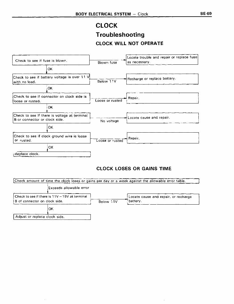
BODY ELECTRICAL SYSTEM - Clock
CLOCK
TroubleshootingCLOCK WILL NOT OPERATE
BE-59
Blown fuseCheck to see if fuse is blown.
OK
Locate trouble and repair or replace fusef------------'--t
as necessary.
Check to see if battery voltage is over 11 Vl-- ~ Recharge or replace battery.with no load. Below 11 V
OK
Check to see if connector on clock side isloose or rusted.
OK
Check to see if there is voltage at terminalB or connector or clock side.
OK
Check to see if clock ground wire is looseor rusted.
OK
Heplace clock.
I------------;~Repair.Loose or rusted
~-------~Locate cause and repair.No voltage
1------:--------:--1 Repa ir.Loose or rusted
CLOCK LOSES OR GAINS TIME
Check amount of time the clock loses or gains per day or a week against the allowable error table.
Exceeds allowable error
Check to see if there is 11 V -15V at terminal
B of connector on clock side.
OK
Adjust or replace clock side.
Locate cause and repair, or rechargeI---B-e-l-o-w-1-1-V--~battery.

BE-70 BODY ELECTRICAL SYSTEM - Clock
1. INSPECT ALLOWABLE ERROR OF CLOCK
Check the allowable error of the clock.
Allowable error (per day): ± 1.5 seconds
2. ADJUSTMENT OF CLOCK
Adjustment of the quartz clock requires a precise digitalcounter. Adjustment must be made in a shop specified bythe manufacturer.
3. SETTING OF CLOCK
(a) Connect the battery terminal.
(b) Check the clock to see that it is running, and then setit to the correct time.
NOTE: Whenever the battery terminal is disconnected,make sure to set the clock to the correct time after reconnecting the battery.