BOC Westbury LNG Facility Final V10...Prepared for BOC Limited, 1 April 2009 J:\JOBS\43283480\6...
83
J:\JOBS\43283480\6 Deliv\DPEMP\BOC Westbury LNG Facility (Final) V10.doc Liquid Natural Gas Facility Westbury, Tasmania DEVELOPMENT PROPOSAL AND ENVIRONMENTAL MANAGEMENT PLAN Liquid Natural Gas Facility Westbury, Tasmania Prepared for BOC Limited 10 Julius Avenue North Ryde NSW 2113 1 April 2009 43283480
Transcript of BOC Westbury LNG Facility Final V10...Prepared for BOC Limited, 1 April 2009 J:\JOBS\43283480\6...

J:\JOBS\43283480\6 Deliv\DPEMP\BOC Westbury LNG Facility (Final) V10.doc Liquid Natural Gas Facility Westbury, Tasmania
D E V E L O P M E N T P R O P O S A L A N D E N V I R O N M E N T A L M A N A G E M E N T P L A N
Liquid Natural Gas Facility Westbury, Tasmania
Prepared for
BOC Limited 10 Julius Avenue North Ryde NSW 2113
1 April 2009
43283480
erin_lovett
Cover Pics

L I Q U I D N A T U R A L G A S F A C I L I T Y W E S T B U R Y , T A S M A N I A
Prepared for BOC Limited, 1 April 2009 J:\JOBS\43283480\6 Deliv\DPEMP\BOC Westbury LNG Facility (Final) V10.doc
Project Manager:
…………………………… Natasha Reifschneider Associate Environmental Planner
Project Director:
…………………………… Jeff Smith Senior Principal Environmental Planner
URS Australia Pty Ltd
Level 6, 1 Southbank Boulevard Southbank VIC 3006 Australia Tel: 61 3 8699 7500 Fax: 61 3 8699 7550
Author:
…………………………… Joel Rodski Environmental Planner
Date: Reference: Status:
1 April 2009 43283480 Final

L I Q U I D N A T U R A L G A S F A C I L I T Y W E S T B U R Y , T A S M A N I A
Foreword
Prepared for BOC Limited, 1 April 2009 J:\JOBS\43283480\6 Deliv\DPEMP\BOC Westbury LNG Facility (Final) V10.doc
This Development Proposal and Environmental Management Plan (DPEMP) has been prepared to support the permit application by BOC Limited (BOC) to the Meander Valley Council for a Liquid Natural Gas (LNG) Facility at Westbury, Tasmania.
The Environment Management and Pollution Control Act 1994 (EMPC Act) provides for the management of the environment and control of pollution and requires certain projects to be subject to an environmental impact assessment process. Types of activities that require assessment, known as Level 2 activities, are determined prior to the lodgement of a permit application, or are ‘called in’ by the Director of the Environment Protection Authority (EPA), where a land use permit is not required.
A Notice of Intent (NOI) was submitted by BOC to the EPA to enable a determination to be made on whether or not the project would require assessment by the Board of the Environment Protection Authority (EPA Board) and the class of assessment that would be required. It was subsequently determined that the project would constitute a Class 2B assessment under the EMPC Act and therefore, a case for assessment in the form of a DPEMP would need to be prepared. The EPA Board issued the BOC Pty Ltd LNG Facility, Westbury, Tasmania – DPEMP Project Specific Guidelines, which along with the Preparation of a Development Proposal and Environmental Management Plan (DPEMP General Guidelines), provide the framework for this document.
This DPEMP will be submitted to Meander Valley Council with the accompanying permit application and subsequently referred to the EPA Board for assessment under the provisions of Section 25 of the EMPC Act.

L I Q U I D N A T U R A L G A S F A C I L I T Y W E S T B U R Y , T A S M A N I A
Table of Contents
Prepared for BOC Limited, 1 April 2009 J:\JOBS\43283480\6 Deliv\DPEMP\BOC Westbury LNG Facility (Final) V10.doc
i
Table of Contents
ES Executive Summary ................................................................................... ES-1
ES 1 Proposal Description................................................................................................ ES-1 ES 2 Existing Environment ............................................................................................... ES-1 ES 3 Potential Effects and Management ......................................................................... ES-1
ES 3.1 Emissions to Air .......................................................................................... ES-1 ES 3.2 Liquid Waste ............................................................................................... ES-2 ES 3.3 Noise........................................................................................................... ES-2 ES 3.4 Dangerous Goods....................................................................................... ES-2 ES 3.5 Biodiversity and Nature Conservation ........................................................ ES-2 ES 3.6 Greenhouse Gases and Ozone Depleting Substances.............................. ES-3 ES 3.7 Heritage ...................................................................................................... ES-3 ES 3.8 Visual Effects .............................................................................................. ES-3 ES 3.9 Socio-economic Issues............................................................................... ES-3 ES 3.10 Health and Safety Issues............................................................................ ES-3 ES 3.11 Hazard Analysis and Risk........................................................................... ES-3 ES 3.12 Infrastructure and Off-site Ancillary Facilities ............................................. ES-4
ES 4 Monitoring and Review............................................................................................. ES-4 ES 5 Decommissioning and Rehabilitation..................................................................... ES-4
1 Introduction ...................................................................................................... 1
1.1 Project Title...................................................................................................................... 1 1.2 Project Proponent ........................................................................................................... 1 1.3 Project Background........................................................................................................ 2
1.3.1 Project Rationale .............................................................................................. 2 1.3.2 Project Components ......................................................................................... 2 1.3.3 Project Location ................................................................................................ 2
1.4 Statutory Requirements ................................................................................................. 3 1.4.1 Commonwealth Legislation .............................................................................. 3 1.4.2 Tasmanian Legislation...................................................................................... 3 1.4.3 Environmental Standards and Guidelines ........................................................ 5 1.4.4 Policies, Strategies and Management Plans.................................................... 5
1.5 Consultation .................................................................................................................... 5

L I Q U I D N A T U R A L G A S F A C I L I T Y W E S T B U R Y , T A S M A N I A
Table of Contents
ii
Prepared for BOC Limited, 1 April 2009J:\JOBS\43283480\6 Deliv\DPEMP\BOC Westbury LNG Facility (Final) V10.doc
2 Proposal Description ....................................................................................... 7
2.1 Proposal Outline.............................................................................................................. 7 2.1.1 Structures.......................................................................................................... 7 2.1.2 Dimensions ....................................................................................................... 8 2.1.3 Car Parking and Access Roads........................................................................ 9 2.1.4 Setbacks ........................................................................................................... 9 2.1.5 Materials and Surfaces ................................................................................... 10
2.2 Process Description ..................................................................................................... 10 2.2.1 Major Equipment Items and Onsite Facilities ................................................. 10 2.2.2 Process Description........................................................................................ 12 2.2.3 Raw Materials ................................................................................................. 13 2.2.4 Waste.............................................................................................................. 14 2.2.5 Air Emissions .................................................................................................. 15 2.2.6 Noise............................................................................................................... 15 2.2.7 Operations ...................................................................................................... 15 2.2.8 Water Supply and Usage................................................................................ 15 2.2.9 Transport......................................................................................................... 15
2.3 Construction and Commissioning .............................................................................. 15 2.4 Site Plan ......................................................................................................................... 15 2.5 General Location Map................................................................................................... 16 2.6 Off-site Infrastructure ................................................................................................... 16 2.7 Technical and Management Alternatives ................................................................... 16
3 Existing Environment..................................................................................... 18
3.1 Planning Aspects .......................................................................................................... 18 3.1.1 Location .......................................................................................................... 18 3.1.2 Land Tenure.................................................................................................... 19 3.1.3 Site History...................................................................................................... 19 3.1.4 Surrounding Industrial Land Use .................................................................... 20 3.1.5 Surrounding Sensitive Land Use .................................................................... 21 3.1.6 Surrounding Recreational and Tourism Related Land Use............................ 21 3.1.7 Planning Scheme Considerations................................................................... 21
3.2 Environmental Aspects ................................................................................................ 22 3.2.1 Meteorology .................................................................................................... 22

L I Q U I D N A T U R A L G A S F A C I L I T Y W E S T B U R Y , T A S M A N I A
Table of Contents
Prepared for BOC Limited, 1 April 2009 J:\JOBS\43283480\6 Deliv\DPEMP\BOC Westbury LNG Facility (Final) V10.doc
iii
3.2.2 Topography..................................................................................................... 22 3.2.3 Geology Geomorphology and Soils................................................................ 23 3.2.4 Vegetation Flora and Fauna ........................................................................... 23
3.3 Socio-economic Aspects ............................................................................................. 23 3.3.1 Demography ................................................................................................... 23 3.3.2 Social .............................................................................................................. 24 3.3.3 Economy......................................................................................................... 24
3.4 Alternative Sites ............................................................................................................ 25
4 Potential Effects and their Management ...................................................... 26
4.1 Air Emissions ................................................................................................................ 26 4.1.1 Legislative and Policy Requirements.............................................................. 26 4.1.2 Performance Requirements............................................................................ 26 4.1.3 Existing Conditions ......................................................................................... 27 4.1.4 Potential Effects.............................................................................................. 28 4.1.5 Avoidance and Mitigation Measures............................................................... 29 4.1.6 Assessment of Effects .................................................................................... 29
4.2 Liquid Waste.................................................................................................................. 30 4.2.1 Legislative and Policy Requirements.............................................................. 30 4.2.2 Assessment of Effects .................................................................................... 30
4.3 Groundwater.................................................................................................................. 34 4.3.1 Legislative and Policy Requirements.............................................................. 34 4.3.2 Assessment of Effects .................................................................................... 34
4.4 Noise Emissions ........................................................................................................... 35 4.4.1 Legislative and Policy Requirements.............................................................. 35 4.4.2 Performance Requirements............................................................................ 35 4.4.3 Existing Conditions ......................................................................................... 36 4.4.4 Potential Effects.............................................................................................. 37 4.4.5 Avoidance and Mitigation Measures............................................................... 39
4.5 Waste Management....................................................................................................... 39 4.5.1 Legislative and Policy Requirements.............................................................. 39 4.5.2 Potential Effects.............................................................................................. 39
4.6 Dangerous Goods......................................................................................................... 39 4.6.1 Legislative and Policy Requirements.............................................................. 40
L I Q U I D N A T U R A L G A S F A C I L I T Y W E S T B U R Y , T A S M A N I A
Table of Contents
iv
Prepared for BOC Limited, 1 April 2009J:\JOBS\43283480\6 Deliv\DPEMP\BOC Westbury LNG Facility (Final) V10.doc
4.6.2 Potential Effects.............................................................................................. 40 4.6.3 Avoidance and Mitigation Measures............................................................... 41
4.7 Biodiversity and Nature Conservation........................................................................ 41 4.7.1 Legislative and Policy Requirements.............................................................. 41 4.7.2 Existing Conditions ......................................................................................... 42 4.7.3 Potential Effects.............................................................................................. 44 4.7.4 Avoidance and Mitigation Measures............................................................... 45 4.7.5 Assessment of Effects .................................................................................... 47
4.8 Marine and Coastal ....................................................................................................... 47 4.9 Greenhouse Gases and Ozone Depleting Substances ............................................. 47
4.9.1 Legislative and Policy Requirements.............................................................. 47 4.9.2 Estimate of Greenhouse Gas Emissions........................................................ 47 4.9.3 Implementing Greenhouse Best Practice ....................................................... 48 4.9.4 Ozone Depleting Substances ......................................................................... 48
4.10 Heritage .......................................................................................................................... 48 4.10.1 Legislative and Policy Requirements.............................................................. 49 4.10.2 Performance Requirements............................................................................ 49 4.10.3 Existing Conditions ......................................................................................... 49 4.10.4 Potential Effects.............................................................................................. 49 4.10.5 Avoidance and Mitigation Measures............................................................... 49 4.10.6 Assessment of Effects .................................................................................... 50
4.11 Land Use and Development ......................................................................................... 50 4.12 Visual Effects................................................................................................................. 50
4.12.1 Existing Visual Setting .................................................................................... 50 4.12.2 Potential Effects.............................................................................................. 50 4.12.3 Avoidance and Mitigation Measures............................................................... 50 4.12.4 Assessment of Effects .................................................................................... 50
4.13 Socio-Economic Issues................................................................................................ 52 4.14 Health and Safety Issues.............................................................................................. 53
4.14.1 Legislative and Policy Requirements.............................................................. 53 4.14.2 Performance Requirements............................................................................ 53 4.14.3 Potential Issues .............................................................................................. 53

L I Q U I D N A T U R A L G A S F A C I L I T Y W E S T B U R Y , T A S M A N I A
Table of Contents
Prepared for BOC Limited, 1 April 2009 J:\JOBS\43283480\6 Deliv\DPEMP\BOC Westbury LNG Facility (Final) V10.doc
v
4.15 Hazard Analysis and Risk Assessment...................................................................... 55 4.15.1 Legislative and Policy Requirements.............................................................. 56 4.15.2 Potential Effects.............................................................................................. 56 4.15.3 Avoidance and Mitigation Measures............................................................... 56 4.15.4 Assessment of Effects .................................................................................... 57
4.16 Fire Risk ......................................................................................................................... 57 4.16.1 Legislative and Policy Requirements.............................................................. 57 4.16.2 Potential Effects.............................................................................................. 58 4.16.3 Avoidance and Mitigation Measures............................................................... 58 4.16.4 Assessment of Effects .................................................................................... 59
4.17 Infrastructure and Off-site Ancillary Facilities........................................................... 59 4.17.1 Road and Traffic Impacts ............................................................................... 59 4.17.2 Electricity ........................................................................................................ 60 4.17.3 Water Supply .................................................................................................. 61 4.17.4 Sewerage........................................................................................................ 61
4.18 Environmental Management Systems ........................................................................ 61
5 Monitoring and Review .................................................................................. 62
6 Decommissioning and Rehabilitation .......................................................... 63
7 Commitments ................................................................................................. 64
8 Conclusion...................................................................................................... 66
9 References...................................................................................................... 67
9.1 Authorities Consulted................................................................................................... 67 9.2 Reference Documents .................................................................................................. 67
10 Limitations ...................................................................................................... 68

L I Q U I D N A T U R A L G A S F A C I L I T Y W E S T B U R Y , T A S M A N I A
Tables, Figures, Plates and Appendices
vi
Prepared for BOC Limited, 1 April 2009J:\JOBS\43283480\6 Deliv\DPEMP\BOC Westbury LNG Facility (Final) V10.doc
Tables, Figures, Plates and Appendices
Tables
Table 1-1 Stakeholder and Community Consultation....................................................................................... 6 Table 2-1 Building and Structure Dimensions.................................................................................................. 9 Table 2-2 Raw Material Requirements........................................................................................................... 14 Table 2-3 Waste Streams............................................................................................................................... 14 Table 3-1 Westbury Climate Statistics ........................................................................................................... 22 Table 3-2 Population of Westbury, Meander Valley, Northern Tasmania and Tasmania.............................. 23 Table 3-3 Building Approval Statistics............................................................................................................ 25 Table 4-1 Ambient Air Quality Criteria............................................................................................................ 26 Table 4-2 EPP (Air Quality 2004), Schedule 1 – In-stack Concentrations..................................................... 26 Table 4-3 70th Percentile Background Concentrations applied to Westbury................................................. 27 Table 4-4 Discrete Receptors......................................................................................................................... 28 Table 4-5 Predicted Maximum Concentrations in the Modelled Area and at the Sensitive Receptors for the
Normal Operation with Tanker Depressurisation Scenario............................................................ 30 Table 4-6 Operational Noise Criteria.............................................................................................................. 35 Table 4-7 Measured Noise Levels - All Locations.......................................................................................... 37 Table 4-8 Predicted Construction Noise Levels ............................................................................................. 38 Table 4-9 Predicted Operational Noise Levels............................................................................................... 38 Table 4-10 Onsite Chemical and Dangerous Goods ....................................................................................... 40 Table 4-11 EPBC Listed Threatened and Migratory Species .......................................................................... 42 Table 7-1 LNG Facility Commitments ............................................................................................................ 64
Figures
Figure 1-1 Westbury Industrial Precinct - Location Map ................................................................................... 2 Figure 2-1 Proposed LNG Facility Site Layout Plan.......................................................................................... 8 Figure 2-2 Process Schematic ........................................................................................................................ 11 Figure 2-3 Site Plan ......................................................................................................................................... 16 Figure 3-1 Westbury Industrial Precinct – Outline Development Plan ............................................................ 18 Figure 3-2 Windrose Charts............................................................................................................................. 22 Figure 3-3 Population Age Distribution............................................................................................................ 24 Figure 4-1 Sensitive Receptor Locations......................................................................................................... 36 Figure 4-2 Green and Gold Frog Habitat Assessment Area ........................................................................... 46

L I Q U I D N A T U R A L G A S F A C I L I T Y W E S T B U R Y , T A S M A N I A
Tables, Figures, Plates and Appendices
Prepared for BOC Limited, 1 April 2009 J:\JOBS\43283480\6 Deliv\DPEMP\BOC Westbury LNG Facility (Final) V10.doc
vii
Plates
Plate 4-1 Eastern View from Bass Highway (west of site) .............................................................................51 Plate 4-2 Southern View from Birralee Road (north of site) ...........................................................................51
Appendices
A General Project Guidelines B Project Specific Guidelines C Air Quality Impact Assessment D Noise Impact Assessment E Flora Values Report F Traffic Impact Assessment G Planning Scheme Considerations H Preliminary Hazard Analysis I Project Location Map J Safety, Health and Environment Plan and Conditions of Readiness K Certificate of Title

L I Q U I D N A T U R A L G A S F A C I L I T Y W E S T B U R Y , T A S M A N I A
List of Abbreviations
viii
Prepared for BOC Limited, 1 April 2009J:\JOBS\43283480\6 Deliv\DPEMP\BOC Westbury LNG Facility (Final) V10.doc
List of Abbreviations
AHD Australian Height Datum
aMDEA activated Methyldiethanolamine
AS Australian Standard
BOC BOC Limited
BOM Bureau of Meteorology
CO2 Carbon Dioxide
dB Decibel
DEWHA Department of Environment, Water, Heritage and the Arts
DPEMP Development Proposal and Environmental Management Plan
EMP Environment Management Plan
EMPC Act Environmental Management and Pollution Control Act 1994
EMPC Board Board of the Environment Management and Pollution Control
EPA Environment Protection Authority, Tasmania
EPBC Act Environment Protection and Biodiversity Conservation Act 1999
EPP Environment Protection Policy
H2S Hydrogen Sulphide
Hr Hour
Kt Kilo tonne
L Litre
LGA Local Government Area
LNG Liquid Natural Gas
LUPA Act Land Use Planning and Approvals Act 1993
MNES Matters of National Environmental Significance
NEPM National Environment Protection Policy
NOI Notice of Intent
NOX Oxides of Nitrogen
NRM Natural Resource Management
RO Reverse Osmosis
RPDC Resource Planning and Development Commission
TGP Tasmanian Gas Pipeline
URS URS Australia Pty Ltd

L I Q U I D N A T U R A L G A S F A C I L I T Y W E S T B U R Y , T A S M A N I A
Executive Summary
Prepared for BOC Limited, 1 April 2009 J:\JOBS\43283480\6 Deliv\DPEMP\BOC Westbury LNG Facility (Final) V10.doc
ES-1
ES Executive Summary
BOC Limited (BOC) is proposing to develop a Liquid Natural Gas (LNG) Facility at a new industrial estate at Westbury. The facility would source natural gas from the Tasmanian Gas Pipeline and convert it into Liquid Natural Gas for use as a heavy vehicle fuel. This Development Proposal and Environmental Management Plan (DPEMP) has been prepared by URS Australia Pty Ltd (URS) on behalf of BOC to support the permit application being made to Meander Valley Council for the proposed LNG Facility.
ES 1 Proposal Description The LNG Facility would source natural gas directly from the Tasmanian Gas Pipeline, which traverses the southern boundary of the site. The natural gas would be purified using an amine solution to absorb carbon dioxide and hydrogen sulphide, dried in an adsorption column and liquefied through a conventional refrigeration process. The LNG would be stored onsite in tanks and transferred to road tankers for distribution around Tasmania.
The proposed LNG Facility would be developed on a greenfield site within the Westbury ‘Trans Central’ Industrial Precinct, being developed to the north of the Tasmanian Alkaloids site in Westbury. The site is considered desirable for industrial development due to access to infrastructure, including road and gas, and adequate buffers from the area to the nearest residences. Prior to the rezoning the site was used for agricultural purposes.
ES 2 Existing Environment The site of the proposed LNG Facility is surrounded by several existing industrial uses, the most significant being the Tasmanian Alkaloids plant adjacent to the southern boundary of the site. The closest existing residences on Birralee are understood to no longer being used for residential purposes after April 2009, nevertheless they have existing use rights which may be maintained and accordingly have been considered as residences in the relevant sections of this DPEMP.
A planning scheme amendment has been approved that will apply site specific industrial zoning provisions to the site of the proposed LNG Facility. The proposed LNG Facility complies with the relevant provisions of the Meander Valley Planning Scheme.
The site of the proposed LNG Facility is flat and is crossed by a shallow man-made drainage line. The drainage line will be realigned and replaced by an underground culvert by the developers of the Westbury Industrial Precinct prior to the site being developed by BOC.
ES 3 Potential Effects and Management A range of potential effects of the proposed LNG Facility have been assessed, the most significant being emissions to air, noise emissions, flora and fauna and risks associated with the storage and processing of compressed and liquefied flammable gas.
ES 3.1 Emissions to Air Waste gases from the proposed LNG Facility will be thermally destroyed in the flare, with no direct venting of gas to atmosphere proposed. Operational emissions to air from the proposed LNG Facility were assessed by considering the three emission scenarios that have the potential to impact on local air quality: normal operation; normal operation and road tanker depressurisation; and plant cold start.
The normal operation in-stack concentration of NOX expressed as NO2 is expected to be more than 80 times under the Air EEP criterion for NO2. In stack concentrations of PM10 are expected to be negligible. Thus, the

L I Q U I D N A T U R A L G A S F A C I L I T Y W E S T B U R Y , T A S M A N I A
Executive Summary
ES-2
Prepared for BOC Limited, 1 April 2009J:\JOBS\43283480\6 Deliv\DPEMP\BOC Westbury LNG Facility (Final) V10.doc
requirements of EPP (Air) for in-stack concentrations are expected to be met and the local air quality is not expected to be adversely affected by the operation of the proposed LNG Facility.
During construction, potential dust emissions can be managed through the use of a Construction Environmental Management Plan.
ES 3.2 Liquid Waste Stormwater runoff from the site would be discharged into the municipal stormwater drain via a sediment interceptor pit. Domestic wastewater produced in the office/workshop area will be discharged to the municipal sewerage system.
Trade wastewater from the demineralised water plant and cooling tower blowdown stream will be discharged to the municipal sewerage system. The average daily volume of trade wastewater will be low and, although it will have elevated total dissolved solids concentrations (relative to town water), will be well under the relevant acceptance criteria.
ES 3.3 Noise Construction and operational noise from the proposed LNG Facility was modelled to determine the noise levels at the nearest residences.
Operational noise was modelled for mechanical equipment that would typically be operating on site. Some of the equipment will be installed with noise mitigation measures such as acoustic enclosure and acoustic cladding that will reduce noise emissions. With the incorporation of noise mitigation into the facility design, predicted noise levels comply with the relative noise criteria at all sensitive locations.
Predicted noise levels during construction are within adopted construction noise limits at all locations except one house on Birralee Road. This house is expected to be vacated from April 2009, and not occupied during construction. However, if the house continues to be occupied during construction and noise complaints are received, BOC would consult with the occupier and an appropriate response would be developed. Construction noise management strategies have been identified to reduce predicted construction noise levels to comply with the relevant criteria at all locations.
ES 3.4 Dangerous Goods Chemicals and dangerous goods proposed to be stored and handled on the site include natural gas, refrigerant gas, aMDEA, compressed nitrogen and hot oil. The main process area will be divided into two concrete bunded areas that have bulk storage capacity greater than the maximum inventories of chemical and dangerous goods stored onsite.
ES 3.5 Biodiversity and Nature Conservation The site of the proposed LNG Facility has been degraded by exotic pasture species to support previous agricultural land uses, and is crossed by a narrow man-made channel that contains several native sedge species. Commonwealth and Tasmanian government ecological databases were searched to determine the likely presence of listed species at the site of the proposed LNG Facility, and, only the Commonwealth listed Green and Gold Frog has been identified as potentially occurring. A Green and Gold frog habitat assessment was conducted for the Trans Central industrial precinct that found that the drainage line that crosses the site of the proposed LNG Facility contains no habitat for the species. The drainage line becomes deeper and better-defined to the west of Birralee Road and may provide some habitat for frogs in transit. A Flora Values Report

L I Q U I D N A T U R A L G A S F A C I L I T Y W E S T B U R Y , T A S M A N I A
Executive Summary
Prepared for BOC Limited, 1 April 2009 J:\JOBS\43283480\6 Deliv\DPEMP\BOC Westbury LNG Facility (Final) V10.doc
ES-3
that specifically assessed the site, found that no threatened flora or fauna species were recorded at the site and that the development would not have any direct impacts on significant natural values. A construction management plan will provide procedures to minimise the potential for introduction of the amphibian chytrid fungus to the area during construction. This will include a requirement to adopt the Tasmanian Washdown Guidelines for Weed and Disease Control: Machinery, Vehicles & Equipment (Edition 1).
ES 3.6 Greenhouse Gases and Ozone Depleting Substances Energy efficient design measures have been incorporated into the design of the proposed LNG Facility and fugitive loses of greenhouse gases have been minimised.
No ozone depleting substances are proposed to be used at the facility.
ES 3.7 Heritage Based on a review of archaeological and historical databases and advice from the Meander Valley Council, it is considered unlikely that Aboriginal or non-Aboriginal cultural heritage sites and areas are present. In the event of discovery of Aboriginal relics, the provisions of the Aboriginal Relics Act 1975 would be followed.
ES 3.8 Visual Effects The bulk of the proposed LNG Facility is low compared to the adjacent industrial development at the Tasmanian Alkaloids plant and would be either blocked by the existing plant, or integrated into the existing view from most vantage points. The industrial precinct will also include visual screening along Birralee Road and escarpment areas of the boundaries of the precinct.
ES 3.9 Socio-economic Issues The proposed LNG Facility would provide a positive contribution to the local and regional economy through the creation of new employment and training requirements. Construction and operation employment not sourced from Westbury would likely be sourced from Launceston.
ES 3.10 Health and Safety Issues The proposed LNG Facility will include a cooling tower, which may present a human health risk if the Legionella bacteria is present. The cooling tower will be designed and managed in accordance with the Australian Standard (AS/NZS 3666.3 Air Handling and Water Systems of Buildings – Microbial Control, Part 2 – Operation and Maintenance) to prevent the risk of Legionella.
Site health and safety during operations will primarily be managed through the development, and effective implementation of a comprehensive Site Safety, Health and Environment Plan (SHE Plan). A draft SHE Plan has already been prepared, which will undergo further and ongoing refinement until site activities commence (and after). A construction phase health and safety management plan will be prepared and implemented by the construction contractor (subject to BOC endorsement).
ES 3.11 Hazard Analysis and Risk A Preliminary Hazard Assessment (PHA) of the proposed facility was conducted to identify associated hazards and assess risks. Seventeen major accident events (MAEs) were identified and the consequences considered to determine the risks to people living and working around the proposed LNG Facility. The analysis found that the proposed LNG Facility complies with the most stringent risk criteria in Australia, mainly that the fatality risk at

L I Q U I D N A T U R A L G A S F A C I L I T Y W E S T B U R Y , T A S M A N I A
Executive Summary
ES-4
Prepared for BOC Limited, 1 April 2009J:\JOBS\43283480\6 Deliv\DPEMP\BOC Westbury LNG Facility (Final) V10.doc
the boundary of the site is predicted to be below the criteria for industrial sites and below the more stringent criteria for commercial sites at the adjacent Tasmanian Alkaloids plant.
ES 3.12 Infrastructure and Off-site Ancillary Facilities A traffic assessment was conducted that predicted traffic volumes that would be generated by the proposed facility, and assessed the capacity of the existing and proposed road network to handle the additional traffic. It was found that all intersections could adequately carry the forecast increased traffic flow.
Other infrastructure including electricity, water, gas and sewerage will be provided as a part of the industrial subdivision.
ES 4 Monitoring and Review Following the consideration of the various potential impacts of the proposed LNG Facility outlined above, it is proposed to conduct some confirmatory monitoring associated with noise and air emissions. The purpose of this monitoring will be to confirm the conclusions of the noise and air impact assessments detailed herein. No ongoing monitoring thereafter is proposed as operation will be constant and therefore associated noise and flare emissions will be consistent.
ES 5 Decommissioning and Rehabilitation The proposed LNG Facility would have an operating life of at least 30 years, however, at this stage no formal timing or process for decommissioning has been established.

L I Q U I D N A T U R A L G A S F A C I L I T Y W E S T B U R Y , T A S M A N I A
Introduction Section 1
Prepared for BOC Limited, 1 April 2009 J:\JOBS\43283480\6 Deliv\DPEMP\BOC Westbury LNG Facility (Final) V10.doc
1
1 Introduction
This Development Proposal and Environmental Management Plan (DPEMP) has been prepared by URS Australia Pty Ltd (URS) on behalf of the project proponent, BOC Limited (BOC), for the proposed construction and operation of a Liquid Natural Gas (LNG) Facility at Westbury, within the Meander Valley municipality, in north-central Tasmania. It has been prepared in accordance with the General Guidelines for the preparation of a Development Proposal and Environmental Management Plan for Level 2 Activities (general project guidelines – refer Appendix A) and the Development Proposal and Environmental Management Plan Project Specific Guidelines for BOC Pty Ltd LNG Facility Westbury, Tasmania (project specific guidelines – refer Appendix B). These guidelines are included in Appendices A and B respectively.
1.1 Project Title The project title is the BOC Westbury LNG Facility. Within this DPEMP document, the project will be referred to as the proposed LNG Facility.
1.2 Project Proponent The proponent of the proposed LNG Facility is BOC Limited (BOC).
BOC is member of The Linde Group, which serves customers in more than 50 countries, 365 days a year and is one of the largest and most global of the world’s leading industrial gases companies. It employs some 50,000 people worldwide.
In the South Pacific, BOC is one of the top 100 companies, with an annual turnover exceeding $A1 billion. The South Pacific, which includes Australia, New Zealand and the Pacific Islands, services over 400,000 customers through 40 production facilities in almost every capital city, 90 retail outlets and more than 1000 agents and equipment partners.
BOC supplies compressed and bulk gasses, chemicals and equipment, developing safe, sustainable and innovative solutions for customers in many speciality sectors, e.g. heavy industry and medical environments. For more than a century BOC’s gases and expertise have contributed to advances in industry and in everyday life, including steelmaking, refining, chemical processing, environmental protection, wastewater treatment, welding and cutting, food processing and distribution, glass production, electronics and health care.
BOC owns and operates one of three existing operating small scale liquefied natural gas plants and facilities in Australia. There are no current proceedings against the proponent within any jurisdiction of law relating to the protection of the environment or the conservation and sustainable use of resources. The following information on the proponent is provided in response to the proponent information requirements of the general and project specific guidelines.
Proponent Name: BOC Limited
Registered Office Address: 10 Julius Avenue, North Ryde, NSW, 2113
ACN: 000 029 729

L I Q U I D N A T U R A L G A S F A C I L I T Y W E S T B U R Y , T A S M A N I A
Section 1 Introduction
2
Prepared for BOC Limited, 1 April 2009J:\JOBS\43283480\6 Deliv\DPEMP\BOC Westbury LNG Facility (Final) V10.doc
1.3 Project Background The project is being developed by BOC to provide the necessary infrastructure to enable the conversion of natural gas to LNG for use as a heavy transport fuel.
1.3.1 Project Rationale The proposed LNG Facility will be capable of producing approximately 50 tonnes of Liquid Natural Gas per day for use as a heavy vehicle fuel. The Westbury facility will process and store natural gas from the Tasmanian Gas Pipeline, prior to it being distributed around Tasmania by road tanker.
The proposed LNG Facility is being developed in conjunction with the conversion of the truck fleets of several Tasmanian transport companies from diesel powered to LNG engines. The Westbury LNG Facility will allow for cheaper transport operation and less environmental emissions.
1.3.2 Project Components The plant and equipment necessary to convert and store the gas are entirely contained within the Westbury site. Section 2 of this DPEMP provides a detailed description of the plant and equipment.
1.3.3 Project Location The project is located on Lot 7 within the recently created industrial precinct, approximately two kilometres north of the Westbury town centre. The industrial precinct, known as the ‘Trans Central Industrial Precinct’ is being developed to facilitate industrial development at a site which has strategic advantages. The precinct includes the existing Tasmanian Alkaloids site and surrounding undeveloped land to the north and north-west as shown on Figure 1-1. A general location map is provided in Appendix I.
Figure 1-1 Westbury Industrial Precinct - Location Map

L I Q U I D N A T U R A L G A S F A C I L I T Y W E S T B U R Y , T A S M A N I A
Introduction Section 1
Prepared for BOC Limited, 1 April 2009 J:\JOBS\43283480\6 Deliv\DPEMP\BOC Westbury LNG Facility (Final) V10.doc
3
1.4 Statutory Requirements 1.4.1 Commonwealth Legislation
Environment Protection and Biodiversity Conservation Act 1999
The Commonwealth Environment Protection and Biodiversity Conservation Act 1999 (EPBC Act) requires that actions that have, will have, or are likely to have a significant impact on matters of national environmental significance, be referred to the Commonwealth Environment Minister for a determination on the level of assessment that would be required.
The ‘Trans Central’ Industrial Precinct was referred to the Commonwealth Department of Environment, Water, Heritage and the Arts (DEWHA) by the Meander Valley Council on 3 June 2008.
As outlined in Section 4 of this DPEMP, it is considered unlikely that the proposed development would have, or are likely to have a significant impact on any of the MNES, and accordingly a referral to DEWHA is not considered necessary.
Other Commonwealth Legislation
Other Commonwealth legislation that may be relevant to the project are as follows:
• Aboriginal and Torres Strait Islander Heritage Protection Act 1984.
• Native Title Act 1993.
1.4.2 Tasmanian Legislation The Tasmanian environmental and planning assessment and approval process is pursuant to the following key legislation:
• Land Use Planning and Approvals Act 1993 (LUPA Act) the subsidiary Meander Valley Planning Scheme; and
• Environmental Management and Pollution Control Act 1994 (EMPC Act).
Both of these Acts operate in conjunction such that the environmental impact assessment is conducted under the provisions of the EMPC Act and the land use planning assessment is conducted under the provisions of the LUPA Act and relevant Planning Scheme. The actual project approval document is the Planning Permit issued under the LUPA Act and relevant Planning Scheme.
Land Use Planning and Approvals Act 1993
The LUPA Act guides development approvals in Tasmania and provides for the preparation of planning schemes by planning authorities, typically local Councils, to regulate land use and development. A permit may be required from the relevant planning authority for land use and development under the provisions of the planning scheme.
The relevant planning authority for the proposed BOC LNG Facility is the Meander Valley Council and the relevant planning scheme is the Meander Valley Planning Scheme 1995.

L I Q U I D N A T U R A L G A S F A C I L I T Y W E S T B U R Y , T A S M A N I A
Section 1 Introduction
4
Prepared for BOC Limited, 1 April 2009J:\JOBS\43283480\6 Deliv\DPEMP\BOC Westbury LNG Facility (Final) V10.doc
Following the approval of draft amendment 1-2008 to the Meander Valley Planning Scheme, the proposed LNG Facility will be zoned Industry. The proposed works are defined as ‘Industry High Impact’ under the Meander Valley Planning Scheme 1995.
A planning permit application will be lodged with Meander Council, which will trigger the submission of this DPEMP to the Environmental Management and Pollution Control (EMPC) Board under the Environmental Management and Pollution Control Act 1994 (EMPC Act).
Environmental Management and Pollution Control Act 1994
The Environmental Management and Pollution Control Act 1994 (EMPC Act) is the main legislation providing for the management of the environment and the management of pollution in Tasmania. A Notice of Intent was submitted to the Board of Environmental Protection Authority (EPA Board) to determine the level of environmental assessment that would be required. It was determined that the proposed LNG Facility requires Level 2B environmental assessment As a planning permit is required under the LUPA Act the proposed development will be referred to for environmental assessment by the planning authority (Meander Valley Council).;.
Other Tasmanian Legislation
Other Tasmanian legislation that may be relevant to the proposal is as follows:
• Aboriginal Relics Act 1975.
• Crown Lands Act 1976.
• Dangerous Goods Act 1998.
• Fire Services Act 1979.
• Forest Practices Act 1985.
• Groundwater Act 1985.
• Historical Cultural Heritage Act 1995.
• Inland Fisheries Act 1995.
• Living Marine Resources Act 1995.
• Mineral Resources Development Act 1995.
• National Environment Protection Council (Tasmania) Act 1995.
• National Parks and Wildlife Act 1970.
• Public Health Act 1997.
• Resource Management and Planning Appeal Tribunal Act 1993.
• Threatened Species Protection Act 1995.
• Water Management Act 1999.
• Weed Management Act 1999.
• Workplace Health and Safety Act 1995.

L I Q U I D N A T U R A L G A S F A C I L I T Y W E S T B U R Y , T A S M A N I A
Introduction Section 1
Prepared for BOC Limited, 1 April 2009 J:\JOBS\43283480\6 Deliv\DPEMP\BOC Westbury LNG Facility (Final) V10.doc
5
1.4.3 Environmental Standards and Guidelines
Environmental Standards
• National Environment Protection (Ambient Air Quality) Measure 2003 (Air NEPM) - Commonwealth
• Environment Protection Policy (Air Quality) - Tasmania
• Environmental Management and Pollution Control (Miscellaneous Noise) Regulations 2004.
• Environmental Management and Pollution Control (Waste Management) Regulations 2000.
• National Greenhouse Strategy
• Workplace Health and Safety Regulations 1998.
• Australia/New Zealand Standard AS/NZS 4360:1995 Risk Management
Environmental Guidelines
• Environmental Guidelines for the Use of Recycled Water in Tasmania, December 2002, Environment Division, Department of Primary Industries, Water and Environment (DPIWE).
• Australian Code for the Transport of Dangerous Goods by Road and Rail
• Tasmanian Forest Practices Code 1995
• State Policy for the Protection of Agricultural Land 2000.
1.4.4 Policies, Strategies and Management Plans • National Strategy for Ecologically Sustainable Development - Commonwealth
• Tasmanian Resource Management and Planning System - Tasmania
• Environmental Management and Pollution Control System – Tasmania
• State Policy on Water Quality Management 1997
• Tasmanian State Coastal Policy 1996.
• National Strategy for the Conservation of Australia’s Biological Diversity
• Draft Tasmanian Nature Conservation Strategy.
• Threatened Species Strategy.
• Tasmanian Regional Forest Agreement (Tasmanian RFA).
• Tasmanian Fire Service Local Area Fire Management Plan.
• Forestry Tasmania Fire Management Plan
1.5 Consultation Stakeholder and community consultation conducted by BOC during the preparation of this DPEMP is outlined in Table 1-1.

L I Q U I D N A T U R A L G A S F A C I L I T Y W E S T B U R Y , T A S M A N I A
Section 1 Introduction
6
Prepared for BOC Limited, 1 April 2009J:\JOBS\43283480\6 Deliv\DPEMP\BOC Westbury LNG Facility (Final) V10.doc
Table 1-1 Stakeholder and Community Consultation
Stakeholders and Residents Consulted
Address Date Issues
Members & Representatives of:
• Westbury Working Together
• Westbury Business Group
• Westbury Hagley Development Association
• Great Western Tiers Tourism Association
• Meander Valley Enterprise Centre
• Deloraine on the Move
• Westbury Rotary
• Deloraine Rotary
• Westbury Apex
• Deloraine Apex
• Westbury Hagley Independent Service Club
10/12/08
Australian Therapeutic Proteins 135 Birralee Rd, Westbury 10/12/08
The leases on the two houses on ATP’s land end early to mid 2009. One may be converted to offices and the other may become a day time farm caretakers accommodation.
Tasmanian Alkaloids 160 Birralee Rd, Westbury 11/12/08 Are interested in the outcome of the
QRA
Mrs B Gibson 310 Birralee Rd, Westbury 11/12/08
Mr F Baker 321 Birralee Rd, Westbury 11/12/08 Only concern was the bright light
from Tasmanian Alkaloids
Mr D Cunningham 206 Birralee Rd, Westbury 11/12/08
Only concern was whether our development could have the potential to reduce the value of the land he was selling as part of the industrial subdivision.
Additional consultation will be occurring in mid-March 2009 through public forums at Westbury and Deloraine.

L I Q U I D N A T U R A L G A S F A C I L I T Y W E S T B U R Y , T A S M A N I A
Proposal Description Section 2
Prepared for BOC Limited, 1 April 2009 J:\JOBS\43283480\6 Deliv\DPEMP\BOC Westbury LNG Facility (Final) V10.doc
7
2 Proposal Description
This section of the DPEMP provides a description of the proposed LNG Facility, including the construction, commissioning, operational and decommissioning phases, as well as infrastructure and offsite ancillary facilities.
2.1 Proposal Outline The BOC Westbury LNG Facility will process natural gas from the Tasmanian Gas Pipeline to produce Liquid Natural Gas for use as a heavy vehicle fuel. The following section provides a general physical description development of the land and structures comprising the proposed LNG Facility. A detailed description of the processes is provided in Section 2.1.2.
2.1.1 Structures The proposed LNG Facility will consist of several buildings, machinery, vessels, equipment skids, storage tanks and stacks.. The ground surface will be concrete in the vicinity of structures and the remainder will be gravel.
Buildings
The proposed LNG Facility will consist of the following buildings:
• Administration Building containing workshop, store, office and bathroom at the rear of the site;
• A small building containing electrical equipment, adjacent to the main office building;
• A small building containing the control room of the proposed LNG Facility; and
• A small shelter adjacent to the truck filling area and a small building containing equipment analysers.
Machinery
The proposed LNG Facility will consist of various machinery required for the manufacture of LNG. A detailed description of the manufacturing process is contained within the following section (Section 2.1.2). The machinery is generally located between truck filling area at the front of the site and the main office building at the rear of the site and is typically contained within vessels or skids and surrounded by bunds. The main items of machinery are:
• Cooling Tower;
• Compressor Skid;
• A rooved Gas Cleaning Area consisting of various pipework and columns including an absorber, stripper and two dehydration vessels;
• Two Cold Boxes (refrigeration unit) (one operational and one spare);
• Tanker Filling pump;
• Gas valve; and
• Tanker Filling Skid (where LNG is loaded into tankers at the front of the site).
Tanks
The proposed LNG Facility contains the following tanks:

L I Q U I D N A T U R A L G A S F A C I L I T Y W E S T B U R Y , T A S M A N I A
Section 2 Proposal Description
8
Prepared for BOC Limited, 1 April 2009J:\JOBS\43283480\6 Deliv\DPEMP\BOC Westbury LNG Facility (Final) V10.doc
• Two LNG storage tanks near the truck filling area at the front of the site;
• Liquid Nitrogen storage tank contained within a storage vessel near the truck filling area at the front of the site; and
• A rainwater tank near the control room building near the rear of the site.
Stacks
The proposed LNG Facility contains one flare stack.
Fences
The site will be contained by an outer and inner security fence and a solid wall will be located at the front of the site.
Figure 2-1 Proposed LNG Facility Site Layout Plan
2.1.2 Dimensions The dimensions (including heights) of the major buildings and structures within the proposed LNG Facility are outlined in Table 2-1.

L I Q U I D N A T U R A L G A S F A C I L I T Y W E S T B U R Y , T A S M A N I A
Proposal Description Section 2
Prepared for BOC Limited, 1 April 2009 J:\JOBS\43283480\6 Deliv\DPEMP\BOC Westbury LNG Facility (Final) V10.doc
9
Table 2-1 Building and Structure Dimensions
Structure Height Dimensions
Administration Building 3.5m 20m by 5m (total area – 100m2)
Transformer Pen N/A 6m x 4m
Motor Control Centre 3.5m 17.5m by 3.5m (total area – 61.25m2)
Cooling Tower 10m Total area – 7m2
Compressor House 3m 18.5m by 4m (total 74m2)
Gas Cleaning Area 6 to 7.7m 31m by 10m (total area – 310m2)
Cold Boxes 8.5m 4.0m2
Absorber 20m 0.5m diameter
Stripper 15m 0.4m diameter
Dehydration Vessels 8m 0.8m diameter
LNG Storage Tanks 27m 4.6m diameter
Flare 10m 2.5m diameter
2.1.3 Car Parking and Access Roads
Car Parking
The proposed LNG Facility includes provision for six car parking spaces adjacent to the Administration Building.
Access Roads
A 26m long 2.5 m wide LNG access road will provide access for LNG Tankers to enter and exit the LNG loading area at the front of the site without having to reverse. The front access road has been designed to cater for B-Double vehicles. The entry and exit points will be controlled by security gates.
An additional access road extends along the eastern site boundary to the rear of the site where the car parking area is located adjacent to the. southern boundary of the property. The development would predominantly consist of industrial machinery required for the production of LNG, including stacks and covered areas
2.1.4 Setbacks
Front Setback
The one metre high brick wall between the truck filling area and the street is setback approximately seven metres from the front site boundary. The Liquid Nitrogen storage tank at the front of the site is setback approximately 17 metres from the site boundary. The inner fence surrounding the plant area is setback approximately 13 metres from the front site boundary.
Side Setbacks
The inner security fence is setback approximately 12 metres from the eastern side site boundary. The side access road and car parking area will be constructed to no less than 3 metres of the eastern side site boundary.
The plant area is located at least 50 metres from the western side site boundary.

L I Q U I D N A T U R A L G A S F A C I L I T Y W E S T B U R Y , T A S M A N I A
Section 2 Proposal Description
10
Prepared for BOC Limited, 1 April 2009J:\JOBS\43283480\6 Deliv\DPEMP\BOC Westbury LNG Facility (Final) V10.doc
Rear Setback
Development at the rear of the site is restricted by the presence of the Tasmanian Gas Pipeline easement. The closest development to the rear site boundary will be the gas off take valve skid which will be approximately 32 metres from the rear site boundary.
2.1.5 Materials and Surfaces The ground surface of the site will be concrete in the vicinity of structures and the remainder will be gravel. The ground surface of the site will be concrete in the vicinity of structures and the remainder will be gravel.
2.2 Process Description The proposed plant will use Natural Gas (NG) from the Tasmanian Gas Pipeline to produce up to approximately 50 tonnes per day of Liquid Natural Gas (LNG) for use as a heavy vehicle fuel.
The process initially involves purifying the pipeline natural gas using an amine solution (‘activated’ methyl diethanol amine or ‘aMDEA’ solution) to absorb residual carbon dioxide and any trace hydrogen sulphide from the NG feedstock. The purified gas is then ‘dried’ by passing it through an adsorption column, whereby any moisture in the NG is removed. Finally the NG is liquefied using a conventional refrigeration process to produce LNG. The LNG will be stored at a pressure of 2 bar in two vacuum insulated tanks with a capacity of 120 tonnes each. The LNG will be transferred to, and be distributed by, road tanker, in either semi-trailer or B-double format, to a series of truck refuelling stations. These truck movements will amount to an average of 2 to 3 per day.
Following absorption of the carbon dioxide and hydrogen sulphide from the feed NG into the amine solution, the amine solution is heated and the extracted gases are desorbed from the solution and sent to a flare. The amine solution is then recycled.
The moisture removed from the purified gas is adsorbed onto a molecular sieve material contained in the drier column. Periodically the column requires regeneration to remove the accumulated moisture. This is achieved by passing a hot gas stream through the molecular sieve bed, which also discharges to the plant flare. A simplified schematic of the process is shown as Figure 2-1.
2.2.1 Major Equipment Items and Onsite Facilities The proposed LNG Facility will consist of the following major equipment, plant and facilities:
• Gas metering and pressure let down station skid;
• CO2 Absorption Unit (to treat gas and remove CO2 and H2S) and Amine Regeneration Unit;
• Dehydration Plant (to remove water from saturated gas);
• Cold Box and Refrigeration Plant;
• LNG Storage Tanks (2 x 120 t);
• Flare System;
• Tanker LNG Loading Facility; and
• Utility systems.

L I Q U I D N A T U R A L G A S F A C I L I T Y W E S T B U R Y , T A S M A N I A
Proposal Description Section 2
Prepared for BOC Limited, 1 April 2009
J:\JOBS\43283480\6 Deliv\DPEMP\BOC Westbury LNG Facility (Final) V10.doc 11
Figure 2-2 Process Schematic

L I Q U I D N A T U R A L G A S F A C I L I T Y W E S T B U R Y , T A S M A N I A
Section 2 Proposal Description
12
Prepared for BOC Limited, 1 April 2009J:\JOBS\43283480\6 Deliv\DPEMP\BOC Westbury LNG Facility (Final) V10.doc
2.2.2 Process Description
Raw Gas Feed
The plant will be supplied with raw feed gas from the Tasmanian gas pipeline via the custody transfer metering skid. After passing through the metering skid the feed gas is mixed with recycled regeneration gas from the dehydration plant at the natural gas ejector point. During this stage the feed gas is metered, warmed and reduced in pressure to the required plant feed pressure of 2,340 kPaG.
This section also incorporates a gas shutdown system, which is part of the plant emergency shutdown system. In the event of an emergency, the feed natural gas is stopped by automatic activation of isolation valves, forming fail safe isolation. Pressure safety valves protect the down stream processing plant from high pressure surges in the event that the pressure control valve incorrectly operates. A regeneration gas ejector has been installed across the pressure let down valve to allow regeneration gas, rich in valuable hydrocarbons, from the dehydration unit to return to the plant feed.
CO2 Absorption Unit
The raw gas then enters the CO2 (carbon dioxide) Absorption Column (C-21) towards the base of the column. Activated methyldiethanolamine (aMDEA) solution is pumped into the column near the top and flows counter-currently to the gas. Carbon dioxide (CO2), hydrogen sulphide (H2S) and some methyl mercaptans are absorbed into the amine solution and consequently removed from the natural gas. The amine stream containing the absorbed gases or ‘rich’ amine solution leaves the bottom of the absorber and passes through filters keeping it free from solids. The ‘sweet’ (i.e. clean) natural gas leaves the top of the absorber column for the dehydration unit.
The rich amine solution is heated by a heat exchanger (against the ‘lean’ amine solution) before discharging into the Amine Regeneration Column (C-22). It is fed into this column near the top. The rich amine solution flows down the column, and is counter-currently contacted with steam rising up the column. This steam strips the absorbed CO2, H2S and other gases from the amine solution. The steam and desorbed gases pass through the top of the column, and are then cooled in the overhead condenser (HE-222) (a heat exchanger) by cooling water, which condenses the steam to water. The condensed water is collected in the Reflux Drum (SP-223), which is returned to C-22 near the top (to help maintain the temperature gradient down the column), as well as the water balance. The desorbed gases pass through the reflux drum and are discharged to flare, where H2S and methyl mercaptan and any other residual hydrocarbons are combusted.
The amine solution that has been stripped of the absorbed gases is referred to a ‘lean’ amine solution. It accumulates in the bottom of Amine Regeneration Column in the Amine Reboiler (RB-221). The stripping steam is generated in the reboiler, which is heated by hot oil (electrically heated in the hot oil heater (HE-29)). The lean amine solution is pumped from the reboiler back to the CO2 Absorption Column (C-21).
The aMDEA solution is comprised of aMDEA concentrate diluted with demineralise water. Water is lost from the system through the CO2 absorption column overhead stream (‘cleaned’ gas stream), which is ‘saturated’ with moisture (which is subsequently removed in the dehydration unit), and to a lesser extent from the C-22 overhead stream. A small amount of aMDEA is lost from the system as carry-over from the C-21 and C-22 overhead streams, as well as a small amount of degradation. aMDEA concentrate and demineralise water make-up streams are required to be added to the amine solution circuit to maintain the chemical and water balances. There is also a produced water stream recycled back from the Dehydration Unit.
The demineralised water is produced onsite from collected rain water and additional potable water as required by a small reverse osmosis demineralised water plant.

L I Q U I D N A T U R A L G A S F A C I L I T Y W E S T B U R Y , T A S M A N I A
Proposal Description Section 2
Prepared for BOC Limited, 1 April 2009 J:\JOBS\43283480\6 Deliv\DPEMP\BOC Westbury LNG Facility (Final) V10.doc
13
Dehydration Unit The ‘sweet’ gas stream from the CO2 Absorption Column is saturated with moisture and removal of water is required before the gas can be fed into the cold box. The sweet natural gas flows through one of two molecular sieve dryer beds (D-25A/B) and any moisture is adsorbed onto the molecular sieve material. The two beds operate alternatively. The online or duty bed is designed to operate for an 8 hour run time. The beds then cycle, with the offline bed coming online. The offline ‘loaded’ bed enters regeneration mode, whereby hot natural gas (electrically heated) is passed counter-currently back through the bed for a period of time to desorb the moisture. This gas stream is cooled by a heat exchanger (against cooling water) to condense water and the regeneration gas is recycled back to the plant NG feed stream (or discharged to flare if the plant is off line). The condensed water is collected in the Regeneration Gas Knock-out Pot (SP-255) and is recycled back into the amine solution. On leaving the dryers the dry gas passes through a dust filter to remove any fine particles and then flows to the cold box.
Cold Box and Refrigeration Plant The sweet dry natural gas then enters the cold box and refrigeration plant for liquefaction. The gas is cooled by the main exchanger (HE-40), referred to as the ‘Cold Box’, in two stages. In the first stage, the gas stream is cooled to about -45oC. The heavier hydrocarbon components of the gas stream mostly condense (almost all propane, butane, pentane and hexane, as well as the large portion of the ethane, and some methane). These condensed liquids are separated from the gas in the LPG Separator Drum (SP-46) and discharged to the flare dump pot (T-961) for vaporisation and flaring. The now predominately methane (with a little ethane) gas stream is then cooled further in the second stage to around -156oC, at which temperature the gas is liquefied. The LNG is then transferred to LNG storage.
The Cold Box is cooled by a hydrocarbon refrigerant. The refrigerant, referred to as MRG, is a blend of nitrogen, methane, ethane, butane and isopentane. The constituent gases are supplied to site as bottled gases for charge into the system. The refrigerant is compressed by a 6-stage Recycle Compressor (CP-30) then liquefied and cooled in three stages, firstly by a water cooled condenser, then in the main heat exchanger (HE-40) and finally expanded across a Joule-Thompson valve. The cold liquefied refrigerant is then heated in the main heat exchanger.
LNG Storage and Tanker Loading After refrigeration, the LNG is discharged to two 120 t capacity LNG storage vessels (T-85A/B) where it is stored prior to distribution. The storage tanks are vacuum insulated pressure vessels. Despite the insulation, a very small amount of gas is vaporised by ambient heating. Pressure in the storage vessels is maintained by a balance header with any excess gas discharged to the flare system primarily to maintain the flare pilot flames. There is also an emergency pressure relief system on the vessels, which also discharges to flare (via the dump pot) in the unlikely event that it was activated.
The LNG is distributed by road tankers, in either semi-trailer or B-double configuration, at the loading bay. It is pumped from storage by a centrifugal submersible cryogenic liquid transfer pump (P85) into road tankers. Typically, 2 to 4 trucks are expected to be filled per day. The tankers are initially top filled to control the pressure in the tanker with the bottom fill valve used to balance the pressure towards the end of the fill process. Infrequently but periodically, road tankers will be partly or wholly depressurised to flare. This is to allow necessary maintenance and inspections of the tankers.
2.2.3 Raw Materials The raw materials required for the proposed LNG Facility, including quantities, characteristics, and options, are listed in Table 2-2.

L I Q U I D N A T U R A L G A S F A C I L I T Y W E S T B U R Y , T A S M A N I A
Section 2 Proposal Description
14
Prepared for BOC Limited, 1 April 2009J:\JOBS\43283480\6 Deliv\DPEMP\BOC Westbury LNG Facility (Final) V10.doc
Table 2-2 Raw Material Requirements
Raw Material Quantity Natural Gas 19,270 t/year Electricity 13,000 MW/a Water 23.2 kL/day
2.2.4 Waste The expected operational waste streams, waste classification indicative quantities, and the proposed waste management measures are described in Table 2-3.
Table 2-3 Waste Streams
Waste Stream Description
Waste Classification
Indicative Quantity
Waste Management
Measures Waste Destinations
Spent Amine Solution (25% w/w ‘activated’ methyldiethanolamine [aMDEA] solution in demineralised water) This will be produced predominantly from the amine absorption column overhead coalescing filter
Controlled Waste Estimated to be approximately 200L per annum. Will be collected in a 200L drum.
The drum will be stored in an adequately bunded area.
This will be sent to Melbourne for disposal
Produced wastewater (demineralised water that may contain a very small amount of residual dissolved ‘light’ hydrocarbons such as butane and pentane)
Liquid Waste 25 L/hr for the first 2 – 4 weeks of operation, and then infrequently for short periods thereafter
This wastewater stream will normally be recycled back to the rich amine solution stream prior to the amine regeneration column, in place of RO make-up
When produced, this will be sent to Melbourne for disposal or Launceston if the hydrocarbon content is low
‘Wet’ (amine area) process bund wastewater – may contain residual lubricating oils.
Liquid Waste Not determined, small. Pumped into 200L drum.
The process bund is roofed to minimise rainwater interception.
This will be sent to Melbourne for disposal unless testing indicates local disposal to Launceston is possible
Filter cartridges (various – 5 filters containing 13 cartridges)
Solid Waste Estimated to be 22 per year.
This will be sent to a controlled land fill site.
Molecular sieve material (gas dryers)
Solid Waste Change-out of 5.6 cubic meters of bed material once every 7 years.
This will be sent to a controlled land fill site.
Waste oils Controlled Waste Small – 200L drums
Appropriate local disposal (or to Melbourne if no suitable local disposal route is identified)

L I Q U I D N A T U R A L G A S F A C I L I T Y W E S T B U R Y , T A S M A N I A
Proposal Description Section 2
Prepared for BOC Limited, 1 April 2009 J:\JOBS\43283480\6 Deliv\DPEMP\BOC Westbury LNG Facility (Final) V10.doc
15
2.2.5 Air Emissions Under normal operating conditions, atmospheric emissions from the proposed LNG Facility would occur from flaring. An assessment of the impacts on air quality of emissions to air is in Section 4.1 of this DPEMP. The air quality assessment of the proposed LNG Facility is included as Appendix C.
2.2.6 Noise The proposed LNG Facility will include various operational plant and equipment with the potential for noise emissions, including from the refrigeration compressor and the associated drive line, let down valve, ejector, cooling tower fan, cooling tower pump, flare and forklifts. Potential noise emissions are assessed in Section 4.4. The noise impact assessment for the proposed LNG Facility is included as Appendix D.
2.2.7 Operations The proposed LNG Facility would require 24 hours per day operation.
2.2.8 Water Supply and Usage The BOC Westbury LNG plant will be supplied with potable water from the municipal system.
Potable water will be used on site for a variety of uses as follows:
• Cooling water system make-up;
• Demineralised water plant supply (to produce a demineralised water product of up to 24 L/hr for discharge into the rich amine solution line prior to discharge into Amine Regeneration Column (C-22));
• Utility hose usage;
• Domestic water use;
• Hydrotesting during commissioning;
• Intermittent process cleaning; and
• Firewater.
2.2.9 Transport There are predicted to be a maximum of 3 LNG tankers, 1 delivery vehicle, and 3 cars each weekday generated by the proposed LNG Facility. Vehicle movements generated by the proposed LNG Facility are predicted to use Birralee Road between the subdivision access road and the Bass Highway interchange. It has been assumed that no vehicle movements would occur on Birralee Road north of the subdivision or south of the Bass Highway interchange.
2.3 Construction and Commissioning Subject to approval from the EPA Board and Meander Valley Council, construction on the site would commence in August 2009.
It is anticipated that the LNG Facility would be commissioned in March 2010.
2.4 Site Plan Figure 2-3 is a site plan showing the layout of the proposed LNG Facility.

L I Q U I D N A T U R A L G A S F A C I L I T Y W E S T B U R Y , T A S M A N I A
Section 2 Proposal Description
16
Prepared for BOC Limited, 1 April 2009J:\JOBS\43283480\6 Deliv\DPEMP\BOC Westbury LNG Facility (Final) V10.doc
Figure 2-3 Site Plan
2.5 General Location Map A general location map of the area surrounding the proposed LNG Facility is contained in Appendix I.
2.6 Off-site Infrastructure The proposed LNG Facility will be located on a lot within the Trans Central Westbury Industrial Precinct subdivision, and it is anticipated that all off-site infrastructure, including roads, electricity, water supply and other utilities will be developed by the Meander Valley Council. A gas off-take will be developed within the proposed LNG Facility to provide a supply of natural gas.
2.7 Technical and Management Alternatives The core of the plant is the refrigeration process. In addition to the chosen mixed refrigerant cycle, a nitrogen based cycle was reviewed and rejected on the basis of inferior process and energy efficiency.
The compressor selected for the refrigeration cycle was a turbo compressor although a positive displacement oil flooded screw compressor was reviewed and rejected on the basis of the maintenance required and higher energy usage.
Carbon dioxide in the natural gas feed stock needs to be removed before the liquefaction process. This removal can be achieved by either an amine solution based extraction process or molecular sieve. The level of carbon dioxide in the feed gas required the use of the amine solution based extraction process.

L I Q U I D N A T U R A L G A S F A C I L I T Y W E S T B U R Y , T A S M A N I A
Proposal Description Section 2
Prepared for BOC Limited, 1 April 2009 J:\JOBS\43283480\6 Deliv\DPEMP\BOC Westbury LNG Facility (Final) V10.doc
17
The sulphur removal process was designed to reject sulphur dioxide to atmosphere albeit in very low quantities. However alternatives were reviewed such as sulphur removal in a sacrificial catalyst bed, with the conclusion that little additional benefit could be achieved due to the very low quantities in the NG feed.
The plant was originally designed for air cooling to aid the modular design approach; however due to both losses in process efficiency and high capital costs the design reverted to a reticulated cooling water system.
Most process plant is installed without any cover being provided. On reviewing the amine solution extraction process and the bunding requirements it was prudent to roof the area to prevent rain water mixing with any amine solution collected in the bund system. Also the second advantage is that the roof enables the collection of storm water for re-use in the cooling water system.
Consideration was also given to using a gas engine to generate power rather than burning the gas via an enclosed flare. However the gas quantity was not sufficiently large enough to make an economic case for a gas engine.
For the storage tanks traditional bunding was rejected in favour of a remotely located containment pit which reduces the risk of fire around the base of the tanks.
The storage location was also carefully considered to minimise the impact to operation and the neighbours in the event of a leak or fire.
The initial storage design was for five 100,000 litre tanks. This was modified to two 300,000 litre tanks to minimise the amount of pipework connecting the tanks together and therefore minimising the potential for leaks.
A recycle compressor for the gas dehydration plant has been replaced by using an ejector and the available pressure in the natural gas supply.

L I Q U I D N A T U R A L G A S F A C I L I T Y W E S T B U R Y , T A S M A N I A
Section 3 Existing Environment
18
Prepared for BOC Limited, 1 April 2009J:\JOBS\43283480\6 Deliv\DPEMP\BOC Westbury LNG Facility (Final) V10.doc
3 Existing Environment
This section of the DPEMP describes the proposed site location and provides an overview of the surrounding existing environment.
3.1 Planning Aspects 3.1.1 Location
Site Location
As outlined in Section 1.3.3, the proposed LNG Facility is located within the Trans Central Industrial Precinct, approximately two kilometres north of the Westbury town centre.
Figure 3-1 Westbury Industrial Precinct – Outline Development Plan
Figure 3-1 is the outline development plan for the undeveloped section of the industrial precinct. The project is located on Lot 7, which is on the southern side of the southern access road to the east of Birralee Road. The southern section of the site is affected by the easement associated with the Tasmanian Gas Pipeline.
BOC has retained an option on two adjacent lots within the Trans Central Industrial Zone at Westbury to allow for the potential future expansion of operating capacity. Any future expansion would be subject to additional transport operators converting their fleet to LNG and sourcing fuel from the Westbury Facility. Although BOC has received enquiries from Tasmanian transport operators, there are no current plans for future expansion.
Location of Associated Infrastructure
The easement associated with the underground Tasmanian Gas Pipeline – Northern Pipeline Extension (Rosevale – Kimberley line) traverses the southern portion of the site. The high pressure underground gas pipeline provides natural gas from the Longford Compressor Station in Victoria to Tasmania, via Bell Bay and Rosevale.

L I Q U I D N A T U R A L G A S F A C I L I T Y W E S T B U R Y , T A S M A N I A
Existing Environment Section 3
Prepared for BOC Limited, 1 April 2009 J:\JOBS\43283480\6 Deliv\DPEMP\BOC Westbury LNG Facility (Final) V10.doc
19
Other reticulated services such as mains water, power supply and sewer are to be provided by the Meander Valley Council as a part of the Trans Central industrial subdivision, in which the proposed LNG Facility is located.
3.1.2 Land Tenure BOC will purchase Lot 7 of the Trans Central Industrial Precinct following the completion of the rezoning and subdivision process.
Property Dimensions
Lot 7 (the site of the proposed Westbury LNG Facility) has the following dimensions:
• Northern boundary: (90.0 metres and 30.1 metres) 120.1 metres
• Eastern boundary: 144.7 metres
• Southern boundary: 120.0 metres
• Western boundary: 140.4 metres.
Property Title
The current applicable title is CT144471/2, a copy of which is provided as Appendix K.
Right of Ways
There is no Right of Way (ROW) on the title for Lot 7 of the Trans Central Industrial Precinct.
Easements
A 20 metre wide easement associated with the underground Tasmanian Gas Pipeline crosses the property adjacent to the southern boundary of the lot.
Covenants
There are no covenants affecting the site.
3.1.3 Site History
Land Use History
The proposed LNG Facility is located within a new industrial subdivision immediately adjacent to the Tasmanian Alkaloid site. The site of the proposed LNG Facility was formerly a part of an agricultural property known as “Roxford”, which was primarily used for grazing. A gas off-take facility for the provision of gas to Tasmanian Alkaloids is located over the pipeline in the vicinity of the proposed LNG Facility site.
Planning History
The proposed LNG Facility site was formerly zoned Rural Zone under the former Meander Valley Planning Scheme 1995. This zoning supported the agricultural use of the land.
Amendment 1/2008 to the Meander Valley Planning Scheme 1995 provided for:
• Rezone 127 hectares of land at Birralee Road, Westbury from Rural Zone to Industrial Zone;

L I Q U I D N A T U R A L G A S F A C I L I T Y W E S T B U R Y , T A S M A N I A
Section 3 Existing Environment
20
Prepared for BOC Limited, 1 April 2009J:\JOBS\43283480\6 Deliv\DPEMP\BOC Westbury LNG Facility (Final) V10.doc
• Incorporate an ‘Outline Development Plan’ with development standards to guide future development on the rezoned area; and
• Delete the existing Special Use Zone Delineated Area (3) from Clause 3.13.4 of the ordinance and the Planning Scheme Plans.
Contamination
The report prepared by the Meander Valley Council to support the amendment to the Meander Valley Planning Scheme to facilitate the industrial rezoning and subdivision states:
“An analysis of historic and current land uses indicates that there is likely to be no contamination issues [and] as a future Industrial Zone, the site will not be subject to any sensitive uses.
There have been no land uses that will result in any long term residues that may be cause for concern, with agricultural chemicals such as pesticides, herbicides and fertilisers being the only applied substances. Due to the likely low levels, any residues from these substances are not regarded as a concern when considering future earth works.” (Meander Valley Council, 2007)
No site testing has been conducted, however based on a site inspection, we have identified no reason to contradict the conclusions of the Council report. There is no visible evidence of contamination from adjacent industrial facilities.
3.1.4 Surrounding Industrial Land Use The proposed LNG facility is located within a new industrial subdivision and will be the first development within the subdivision to occur. There are however, several existing industrial land uses within and adjacent to the industrial subdivision, as outlined in the following sub-sections.
D J Machinery
D J Machinery is a machinery fabrication, repairs and sales business located approximately 400 metres north-west of the proposed LNG Facility. D J Machinery has frontage onto Birralee Road, currently has access onto Birralee Road by an access road (shared with neighbouring Tasbuilt Homes) and will be located on the north-eastern corner of the intersection of Birralee Road and the northern access road.
Tasbuilt Homes
Tasbuilt Manufactured Homes and Cabins is a manufacturer of portable buildings located approximately 400 metres north-west of the proposed LNG Facility, to the east of D J Machinery. Access from Tasbuilt Homes onto Birralee Road is by a shared access road (with D J Machinery) that will become the northern access road into the subdivision.
Tasmanian Alkaloids
Immediately south of the proposed LNG Facility is the Tasmanian Alkaloids operations plant where poppies are processed into pharmaceutical products. The plant occupies a 23 hectare lot between the industrial subdivision and the Bass Highway and comprises storage and processing sheds, processing infrastructure, office facilities, car parking and plant, and wastewater dams. The facility is developed up to its northern boundary adjacent to the proposed LNG Facility.

L I Q U I D N A T U R A L G A S F A C I L I T Y W E S T B U R Y , T A S M A N I A
Existing Environment Section 3
Prepared for BOC Limited, 1 April 2009 J:\JOBS\43283480\6 Deliv\DPEMP\BOC Westbury LNG Facility (Final) V10.doc
21
Filling Station
An un-manned filling station is located on the western side of Birralee Road approximately 200 metres south-west of the proposed LNG Facility. The filling station is used by heavy vehicles.
Readymix Concrete Batching Plant
The Readymix Concrete Batching Plant is located on the western side of Birralee Road approximately 500 metres north-west of the proposed LNG Facility.
3.1.5 Surrounding Sensitive Land Use Sensitive land uses, including residences, schools, hospitals and caravan parks, located within one kilometre of the proposed LNG Facility are described in the following sub-sections.
Residences
There are three existing residences located within one kilometre of the proposed LNG Facility as follows:
• Birralee Road (west) House opposite Tasmanian Alkaloids (north);
• Birralee Road (west) House opposite Tasmanian Alkaloids (south); and
• Lyttleton Street (north) House “Danville”.
It should be noted that the closest residences on Birralee Road are owned by Australian Therapeutical Products, and currently leased until April 2009. After this, it is understood that the properties will no longer be occupied for residential purposes. Nevertheless they have existing use rights, which may be maintained and accordingly have been considered as residences in the relevant sections of this DPEMP.
Other Sensitive Uses
There are no other sensitive land uses such as schools, hospitals and caravan parks located within one kilometre of the proposed LNG Facility.
3.1.6 Surrounding Recreational and Tourism Related Land Use There are no recreational or tourism related land uses, such as camping areas, picnic areas, walking tracks or historic routes located within the vicinity of the proposed LNG Facility.
The “village” of Westbury contains over 20 places listed on the Register of the National Estate, and 28 places on the Tasmanian Heritage Register. The Great Western Tiers historic route follows the old Bass Highway through the centre of Westbury in an east-west direction.
3.1.7 Planning Scheme Considerations The Meander Valley Planning Scheme 1995 contains specific information requirements relating to the Industrial Precinct (RPDC approved Clause 3.5.4) and general information requirements (Clause 2.10) relating to the consideration of planning permits. A discussion of all of the relevant considerations of the Meander Valley Planning Scheme, including appropriate cross-referencing to the relevant section of this DPEMP, is contained in Appendix G.

L I Q U I D N A T U R A L G A S F A C I L I T Y W E S T B U R Y , T A S M A N I A
Section 3 Existing Environment
22
Prepared for BOC Limited, 1 April 2009J:\JOBS\43283480\6 Deliv\DPEMP\BOC Westbury LNG Facility (Final) V10.doc
3.2 Environmental Aspects 3.2.1 Meteorology Westbury has a temperate climate with warmest temperatures experienced in summer and coldest in winter. Reliable rainfall is experienced throughout the year with the maximum amount occurring in July. Bureau of Meteorology (BOM) climate statistics from the Westbury (Valley View) site are summarised in Table 3-1.
Table 3-1 Westbury Climate Statistics
JAN FEB MAR APR MAY JUN JUL AUG SEP OCT NOV DEC ANNUAL
Av Max (°C) 23.4 23.4 21.0 17.1 13.8 10.0 9.7 11.9 14.5 16.9 19.4 21.8 16.9
Av Min (°C) 8.2 8.5 7.2 4.7 2.4 1.0 0.6 1.7 3.0 4.4 5.8 7.5 4.6
Av Rainfall (mm)
45.5 46.9 46.1 64.6 77.3 85.8 102.6 94.4 81.4 74.6 56.8 55.8 832.2
Source: Bureau of Meteorology
The BOM Westbury climate data does not include statistics on winds. The nearest stations that have data on winds are Launceston and Sheffield, however, winds at these locations appear to be influenced by the local topography, in particular the Tamar Valley in Launceston and the Forth Valley in Sheffield, which provide protection from winds in certain directions and channel winds in others. Based on the topographical conditions surrounding Westbury, the predominant wind direction is predicted to be from the west and north-west as shown in Figure 3-2.
Figure 3-2 Windrose Charts
3.2.2 Topography The proposed LNG Facility site is relatively flat rising from approximately 182 metres (AHD) in the south-west of the site to approximately 185 metres (AHD) in the north-east of the site. A shallow man-made drainage line crosses the southern portion of the site from east to west.
Westbury Sheffield Launceston

L I Q U I D N A T U R A L G A S F A C I L I T Y W E S T B U R Y , T A S M A N I A
Existing Environment Section 3
Prepared for BOC Limited, 1 April 2009 J:\JOBS\43283480\6 Deliv\DPEMP\BOC Westbury LNG Facility (Final) V10.doc
23
3.2.3 Geology Geomorphology and Soils The proposed LNG Plant site appears to be located within Eastfield Association and in close proximity to a small area of Cressy Association close to Birralee Road. The main characteristics of these soils are as follows.
Cressy Association (Cs)
Cressy Association soils have a gradational profile, i.e. clay content increases with increasing depth. The soils have dark brown clay loam topsoils with strongly developed friable structure. They have heavy clay subsoils with variable amounts of ironstone gravels present and are moderately well drained (Grose and Moreton 1996).
Eastfield Association (Ea)
Eastfield Association soils [are] developed on dolerite bedrock and colluvium on rolling to steep land… rock outcrop and loose stone are limiting factors (Spanswick and Zund 1999).
Tm – Marine limestone
Ts – Dominantly non-marine sequences of gravel, sand, silt, clay and regolith
3.2.4 Vegetation Flora and Fauna The site of the proposed LNG Facility is dominated by exotic grasses as a result of previous agricultural land use. The shallow man-made drain that crosses the subject site contains scattered native sedge species. The remainder of the site contains no significant native vegetation.
3.3 Socio-economic Aspects 3.3.1 Demography Table 3-2 displays the population and rate of population growth of the Meander Valley LGA and Westbury urban centre at the 1996, 2001 and 2006 Census of Population and Housing and displays the equivalent statistics for the Northern Tasmania Statistical Division and the State of Tasmania by way of comparison.
Table 3-2 Population of Westbury, Meander Valley, Northern Tasmania and Tasmania
Area Population
(1996) Population
(2001) Population
(2006) % Change
(1996-2001) % Change
(2001-2006) % Change
(1996-2006)
Westbury 1,280 1,241 1,358 -3.05% 9.43% 6.09% Meander Valley 16,773 17,375 18,066 3.59% 3.98% 7.71% Northern Tasmania 129,764 128,649 132,662 -0.86% 3.12% 2.23% Tasmania 459,659 456,652 470,794 -0.65% 3.10% 2.42%
Table 3-2 shows that the population of the Meander Valley LGA has grown at a faster rate than the Statistical Division of Northern Tasmania and the State of Tasmania, while the urban centre of Westbury, despite losing a larger percentage of its population from the period of 1996 to 2001, gained population at a higher rate than the Meander Valley LGA between 2001 and 2006, and had a higher rate of growth for the 1996 to 2006 period than the Northern Tasmania Statistical Division and the State of Tasmania.
The Meander Valley LGA and Westbury Urban Centre/Locality have similar age structures to wider Northern Tasmania and Tasmania areas with slightly fewer persons aged between 20 and 35 and slightly more people aged over 55 as demonstrated in Figure 3-3.
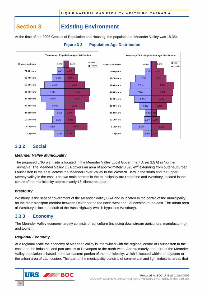
L I Q U I D N A T U R A L G A S F A C I L I T Y W E S T B U R Y , T A S M A N I A
Section 3 Existing Environment
24
Prepared for BOC Limited, 1 April 2009J:\JOBS\43283480\6 Deliv\DPEMP\BOC Westbury LNG Facility (Final) V10.doc
At the time of the 2006 Census of Population and Housing, the population of Meander Valley was 18,354.
Figure 3-3 Population Age Distribution
Tasmania - Population age distribution
2.9%
6.8%
3.4%
3.1%
6.0%
7.3%
7.5%
6.0%
3.9%
2.9%
0.6%
2.2%
3.6%
6.0%
7.2%
6.9%
5.6%
3.1%
3.6%
7.1%
3.1%
1.2%
0-4 years
5-14 years
15-19 years
20-24 years
25-34 years
35-44 years
45-54 years
55-64 years
65-74 years
75-84 years
85 years and overMale
Female
Westbury TAS - Population age distribution
2.2%
6.9%
2.9%
1.8%
5.2%
6.9%
7.4%
7.7%
5.0%
4.3%
2.9%
6.7%
2.6%
2.2%
4.3%
5.9%
7.8%
7.3%
5.5%
2.2%
0.6% 1.7%
0-4 years
5-14 years
15-19 years
20-24 years
25-34 years
35-44 years
45-54 years
55-64 years
65-74 years
75-84 years
85 years and overMale
Female
3.3.2 Social
Meander Valley Municipality
The proposed LNG plant site is located in the Meander Valley Local Government Area (LGA) in Northern Tasmania. The Meander Valley LGA covers an area of approximately 3,320km2 extending from outer-suburban Launceston in the east, across the Meander River Valley to the Western Tiers in the south and the upper Mersey valley in the east. The two main centres in the municipality are Deloraine and Westbury, located in the centre of the municipality approximately 15 kilometres apart.
Westbury
Westbury is the seat of government of the Meander Valley LGA and is located in the centre of the municipality on the main transport corridor between Devonport to the north-west and Launceston to the east. The urban area of Westbury is located south of the Bass Highway (which bypasses Westbury).
3.3.3 Economy The Meander Valley economy largely consists of agriculture (including downstream agricultural manufacturing) and tourism.
Regional Economy
At a regional scale the economy of Meander Valley is intertwined with the regional centre of Launceston to the east, and the industrial and port access at Devonport to the north-west. Approximately one-third of the Meander Valley population is based in the far eastern portion of the municipality, which is located within, or adjacent to the urban area of Launceston. This part of the municipality consists of commercial and light industrial areas that

L I Q U I D N A T U R A L G A S F A C I L I T Y W E S T B U R Y , T A S M A N I A
Existing Environment Section 3
Prepared for BOC Limited, 1 April 2009 J:\JOBS\43283480\6 Deliv\DPEMP\BOC Westbury LNG Facility (Final) V10.doc
25
are reliant on the economy of the Greater Launceston area. The economy of the remainder of the municipality mainly consists of small business spread throughout the rural areas, concentrated around the towns of Deloraine and Westbury.
The upgrade and realignment of the Bass Highway to bypass, while initially opposed due to loss of highway traffic business, has improved accessibility of the Meander Valley to the rest of Tasmania and seaports, and enabled the creation of the Great Western Tiers Tourist Route, a key driver of tourism related business.
Local Economy
Tasmanian Alkaloids, the largest single manufacturing business in Meander Valley employing over 200 people, is based in Westbury. The remainder of the Westbury economy mainly consists of small agricultural and tourism related businesses.
As at the 2006 census of population and housing, the unemployment rate in Westbury was 6.96%. 15% of employed persons in Westbury work in the manufacturing industry, which is relatively high compared to the Meander Valley municipality. Other significant employment industries are health care and social assistance (12%) and retail trade (11%).
Statistics relating to building approvals in Westbury, provided by the Meander Valley Council, are presented in Table 3-3 below.
Table 3-3 Building Approval Statistics
Year Number Value ($) 1999/2000 3 288,000 2000/2001 6 528,200 2001/2002 5 425,609 2002/2003 13 1,273,157
3.4 Alternative Sites The following Tasmanian locations were also considered by BOC prior to the selection of the Westbury site.
Bell Bay
The Bell Bay Industrial area was explored as a potential site for the LNG Facility. However, land is in short supply at Bell Bay and the only suitably sized plot that was available was 1.5km from the Tasmanian Gas Pipeline and seven kilometres from the nearest available take off point. On this basis, the Bell Bay site was rejected as the pipeline costs would be prohibitive.
Longford
The township of Longford was also explored as there is an existing gas off take nearby. However, the land adjacent to the gas off-take required rezoning from rural to industrial and a previous rezoning application had been refused.

L I Q U I D N A T U R A L G A S F A C I L I T Y W E S T B U R Y , T A S M A N I A
Section 4 Potential Effects and their Management
26
Prepared for BOC Limited, 1 April 2009J:\JOBS\43283480\6 Deliv\DPEMP\BOC Westbury LNG Facility (Final) V10.doc
4 Potential Effects and their Management
This section of the DPEMP identifies existing conditions, applicable legislation and regulations and performance requirements in relation to potential effects of the proposed LNG Facility, outlines avoidance and mitigations measures, and provides an overall assessment of the likely impacts.
4.1 Air Emissions This section of the DPEMP outlines potential effects of air emissions from the proposed Westbury LNG Facility and their management.
4.1.1 Legislative and Policy Requirements The legislative and policy requirements relating to air emissions, relevant to the proposed LNG Facility are:
• Environment Protection Policy (Air Quality) - (Air EPP).
• National Environment Protection (Ambient Air Quality) Measure 2003 (Air NEPM).
4.1.2 Performance Requirements These policy requirements have been used to derive facility performance requirements (Table 4-1 and Table 4-2). NEPM standards are intended to be applied at monitoring locations that represent air quality for a region or sub-region of more than 25,000 people, and are not used as recommendations for locations near industrial facilities. For this reason, the NEPM standards have been applied at the Westbury Township only.
Table 4-1 Ambient Air Quality Criteria
Pollutant Averaging
Time Air Quality Standard
Air Quality Standard (converted at 1 atm,
25 °C) Source
Carbon Monoxide (CO) 8-hour 9 ppm 10,300 μg/m3 NEPM & EPP
1-hour 0.12 ppm 230 μg/m3 NEPM
1-hour 0.16 ppm 300 μg/m3 EPP Nitrogen Dioxide (NO2)
1-year 0.03 ppm 56 μg/m3 NEPM
1-hour 0.20 ppm 520 μg/m3 NEPM & EPP
1-day 0.08 ppm 210 μg/m3 NEPM Sulphur Dioxide (SO2)
1-year 0.02 ppm 52 μg/m3 NEPM
Hydrogen Sulphide (H2S) 3-minute 0.0001 ppm 0.14 μg/m3 EPP
Methyl mercaptan 3-minute 0.00042 ppm 0.83 μg/m3 EPP
n-Pentane 3-minute 20 ppm 60,000 μg/m3 EPP
n-Hexane 3-minute 1.67 ppm 6,000 μg/m3 EPP
Table 4-2 EPP (Air Quality 2004), Schedule 1 – In-stack Concentrations
Pollutant Source In-stack Concentration
Oxides of Nitrogen (NOx) Any trade, industry or process other than for the manufacture of glass using sodium nitrate 2.0 g/m3 (as NO2)
Particulate Matter (PM10) Any trade, industry or process and any fuel burning equipment or industrial plant 100 mg/m3

L I Q U I D N A T U R A L G A S F A C I L I T Y W E S T B U R Y , T A S M A N I A
Potential Effects and their Management Section 4
Prepared for BOC Limited, 1 April 2009 J:\JOBS\43283480\6 Deliv\DPEMP\BOC Westbury LNG Facility (Final) V10.doc
27
4.1.3 Existing Conditions Ambient Monitoring Ambient monitoring of air quality is not currently undertaken in Westbury, however monitoring is undertaken in Launceston and George Town. For these two monitoring locations, it was determined that George Town’s air quality was the most analogous to Westbury because the size of the residential area of Westbury is closer to Georgetown’s residential area. As significant air quality impacts at Launceston are caused by residential sources, it was considered that Launceston air quality would be an overly conservative (i.e. poor) estimate in the cold months. Due to these reasons, George Town monitoring data was used for all substances except for CO, pentane, hexane, H2S and methyl mercaptan as they are not monitored at George Town.
As different meteorology is expected at Westbury, in comparison to George Town, daily concentration data was not used in the dispersion model. In accordance with Schedule C of Victoria’s State Environment Protection Policy (Air Quality Management) (SEPP (AQM)), the 70th percentile of monitored data was used as the background value and was consistently applied across the dispersion modelling domain. As CO was monitored at Launceston a 70th percentile value was derived from that monitoring data set. For all datasets used, the values were screened and missing or negative values removed before calculation of the 70th percentile.
The background data applied to Westbury is provided in Table 4-3.
Table 4-3 70th Percentile Background Concentrations applied to Westbury
Substance Concentration
(µg/m3) Monitoring Period Used
NOX 8.0 21/07/2007 - 30/09/2008
CO 0.62 17/05/2007 – 28/12/2007
(Not monitored at George Town, Launceston data used)
SO2 1.6 21/07/2007 - 30/09/2008
H2S - Not monitored
Methyl Mercaptan - Not monitored
Pentane - Not monitored
Hexane - Not monitored
Gas concentrations are expressed at 1 Atm and 25 °C.
Other Industry in the Area The site is understood to be a green field site with a factory that produces pharmaceutical products on the southern boundary of the proposed site. Emissions from this bordering facility are unknown other than that which was reported to the National Pollutant Inventory (NPI). The masses for these emissions are ranked as “Low” and in the bottom 1% of all facilities reported to the NPI for those substances. Based on this, and in the absence of more representative or site specific data, emissions from Tasmanian Alkaloids were not included in the impact assessment.
Non-industrial Sources Non-industrial sources such as roads and emissions from housing have been taken in to account in the modelling by using Ausroads to model the effect of traffic on local air quality and the background monitoring to take in to account the affect of emissions from housing.

L I Q U I D N A T U R A L G A S F A C I L I T Y W E S T B U R Y , T A S M A N I A
Section 4 Potential Effects and their Management
28
Prepared for BOC Limited, 1 April 2009J:\JOBS\43283480\6 Deliv\DPEMP\BOC Westbury LNG Facility (Final) V10.doc
Sensitive Receptors The closest residence to the proposed LNG Facility is approximately 500m to the south west. Eight other residences were identified as being near to the site and were included in the air quality assessment as discrete receptors. The locations are shown in Table 4-4.
Table 4-4 Discrete Receptors
Receptor ID Location
R1 Birralee Rd, 1.9km north of plant
R2 Birralee Rd, 0.6km north west of plant
R3 Birralee Rd, 0.3km south west of plant
R4 Lyttleton St, 0.9km south east of plant
R5 Lyttleton St, 1.2km south east of plant
R6 Lyttleton St, 1.6km south east of plant
R7 Waterloo St, 1.6km south-south east of plant
R8 Birralee Rd, 1.0km south-south east of plant
R9 Emu Plain Rd, 1.8km east of plant
4.1.4 Potential Effects
Construction Construction of the proposed LNG Facility will last for approximately 9 months. During this time, activities and events with the potential to cause dust emissions could include:
• Excavation of topsoil and landform activity;
• Soil handling;
• Vehicle movement on dirt surfaces; and
• Wind erosion of exposed areas.
Operation – Local Air Quality The air quality assessment considered three emission scenarios that are expected to occur under normal operation. The three scenarios were selected as they have the potential for greatest impact on local air quality through atmospheric emissions from the flare and conservatively used worst case gas composition. Intermittent sources to the flare that were included in the scenarios were modelled as being continuous so that all hours of the modelled year could be considered for impacts. The emission constituents of interest were flare gasses and products of combustion. The scenarios were:
1) Normal Operation;
2) Normal Operation and Road Tanker Depressurisation; and
3) Plant Cold Start.
Plant upset scenarios were assessed in the hazard analysis and risk assessment. As such, they were not considered in the air quality assessment.

L I Q U I D N A T U R A L G A S F A C I L I T Y W E S T B U R Y , T A S M A N I A
Potential Effects and their Management Section 4
Prepared for BOC Limited, 1 April 2009 J:\JOBS\43283480\6 Deliv\DPEMP\BOC Westbury LNG Facility (Final) V10.doc
29
4.1.5 Avoidance and Mitigation Measures Construction Control of potential dust emissions during construction will be managed through the use of a construction Environmental Management Plan (EMP). The construction EMP will include options for dust mitigation that will be implemented as required:
• Minimisation of drop heights;
• Undertaking of earthworks during periods of when soil moisture content is enough to suppress dust emissions from earthworks;
• Introduction of speed limits to minimise dust generation from unmade roads;
• Limitation of the use of non-essential vehicles on site;
• Covering of loads of excavated material;
• Minimisation of stockpile area to reduce wind erosion;
• Periodic watering of exposed land during extended dry periods;
• Watering of long term undisturbed stockpiles and stockpiles considered to be causing an offsite impact; and
• Use of vegetation on stockpiles with a static residence time of longer than 3 months.
Operation Waste gasses from the LNG production process will be thermally destroyed in the flare. The flare is designed to accommodate gas flows under normal and upset operation. Additionally gasses from LNG volatilisation and road tanker depressurisation will also be fed to the flare. No direct venting of gas to atmosphere is proposed.
Process pipework will be checked for fugitive leaks upon commissioning and after maintenance.
The initial LNG storage design was for five 100,000 litre tanks. This was modified to two 300,000 litre tanks to minimise the amount of pipework connecting the tanks together. This minimised the potential for pipework leaks.
4.1.6 Assessment of Effects In Stack Concentrations The normal operation in-stack concentration of NOX expressed as NO2 is expected to be more than 80 times under the Air EEP criterion for NO2. In stack concentrations of PM10 are expected to be negligible. Thus, the guidelines of EPP(Air) for in-stack concentrations are expected to be met.
Local Air Quality Modelled results of emission dispersion indicated that normal operation with tanker depressurisation results in the highest ground level concentrations of considered species. Table 4-5 shows the predicted maximum concentrations in the modelled area. It shows that the predicted concentrations for this maximum impact scenario are well below the assessment criteria indicating that local air quality will not be adversely affected by normal operation of the plant.
Concentrations at the discrete receptors (Table 4-4) were lower than the maximums reported in Table 4-5, and due to this, the facility is not expected to adversely impact air quality at these locations. It is proposed that one air quality monitoring event will occur on commissioning of the proposed LNG Facility to confirm the conclusions of the air quality impact assessment.

L I Q U I D N A T U R A L G A S F A C I L I T Y W E S T B U R Y , T A S M A N I A
Section 4 Potential Effects and their Management
30
Prepared for BOC Limited, 1 April 2009J:\JOBS\43283480\6 Deliv\DPEMP\BOC Westbury LNG Facility (Final) V10.doc
Table 4-5 Predicted Maximum Concentrations in the Modelled Area and at the Sensitive Receptors for the Normal Operation with Tanker Depressurisation Scenario
Pollutant Averaging
Time
Criteria (µg/m3 at 1 atm, 25 °C)
Maximum On the Model
Domain (µg/m3)
Carbon Monoxide (CO) 8-hour 10300 92
1-hour 230
1-hour 300 71
Nitrogen Dioxide (NO2)
1-year 56 12.4
1-hour 520 2.10
1-day 210 1.76 Sulphur Dioxide (SO2)
1-year 52 1.61
Hydrogen Sulphide (H2S) 3-minute 0.14 0.0012
Methyl Mercaptan 3-minute 0.83 0.0120
Pentane 3-minute 60,000 0.88
Hexane 3-minute 6,000 0.73
4.2 Liquid Waste This section of the DPEMP outlines the potential effects and management of liquid waste from the proposed LNG Facility.
4.2.1 Legislative and Policy Requirements The legislative and policy requirements relating to liquid waste, relevant to the proposed LNG Facility are:
• Inland Fisheries Act 1995.
• Living Marine Resources Management Act 1995.
• State Policy on Water Quality Management 1997 (Water Policy).
• Tasmanian State Coastal Policy 1996.
• Water Management Act 1999.
• Plumbing Regulations 2004.
4.2.2 Assessment of Effects Stormwater Stormwater runoff from the site will be discharged into the underground municipal stormwater drain pipeline that will run along the northern and western boundary of the site. The stormwater drainage system will operate on gravity only. The onsite stormwater collection system will be at surface only (spoon and channel drains and kerbing). The stormwater runoff will pass though a sediment interceptor pit prior to discharge offsite.
Site surfaces will include course gravel (‘blue metal’), bitumen roadways and hardstand areas (bitumen), and concrete process areas, including bunds. A relatively small bunded process area of the site will be covered by an awning to minimise rainwater ingress (as this water will be collected for offsite disposal). Runoff from the

L I Q U I D N A T U R A L G A S F A C I L I T Y W E S T B U R Y , T A S M A N I A
Potential Effects and their Management Section 4
Prepared for BOC Limited, 1 April 2009 J:\JOBS\43283480\6 Deliv\DPEMP\BOC Westbury LNG Facility (Final) V10.doc
31
awning will be collected in a rainwater tank, which will be used to supply the demineralised water plant (reverse osmosis treatment), with portable water make-up as backup. Provision will also be made to potentially supply the cooling water system from the rainwater tank. The rainwater tank overflow will discharge to grade. As the process area is separately bunded, the only potential contaminant in stormwater runoff from the site is sediment.
There is a containment pit located adjacent to the road tanker loading bay, which is an emergency structure for use in the event of a significant loss of containment of liquefied gas during tanker loading or from the process. This pit is open at the top and will accumulate some rainwater. A manually operated pump will be installed to pump accumulated stormwater from this pit to the site stormwater drainage system as required.
Sewerage
Domestic wastewater will be produced in the office/store/workshop/toilet building, from toilet flushing, urinals, hand basins and sinks. This wastewater will be discharged to the municipal sewerage system. During operation there will normally only be two operators present onsite, plus tanker drivers, so domestic wastewater production is expected to be relatively small (about 100 L/d or less on average).
During the construction phase, portable sanitation facilities will be installed at the site. Domestic wastewater will be contained in these facilities, and will be pumped out by a contractor for offsite disposal.
Trade Waste
It is proposed to discharge two trade wastewater streams to sewer from the facility, as follows:
• Demineralised water plant reverse osmosis unit reject stream; and
• Cooling tower blowdown stream.
The sources and characteristics of these streams are discussed in the respective subsections (following this subsection).
It is also proposed to connect the sump located in the ‘dry’ process bund (containing the dehydration plant, which is a ‘dry’ operation) to sewer (requiring manual drainage). The only liquid that would be expected to enter this bunded area would be wind blown rain (the bund will be covered). It is proposed to direct the bund to sewer rather than stormwater because it is a process area.
The average daily trade waste discharge volume will be very low, estimated at this stage to be about 0.1 kL/hr, resulting in an estimated daily average flow of about 2.5 kL/d. The blowdown rate will vary seasonally (due to higher evaporation rates in warmer weather) and may at times be twice as much as the current estimated average (on a daily basis). The discharge rate will be controlled such that it does not ever exceed a rate equivalent to 1 kL/hr. This will be achieved through the design of the cooling tower and RO plant discharge arrangements. There will be a physical restriction (not just manual valve throttling) and consideration will be given to account for the potential for the cooling tower and RO plant to be discharging at the same time.
The peak daily trade waste volume would be 24 kL/d, which could occur if the cooling tower is required to be drained for maintenance (would take about 1.5 days to drain at the 1 kL/d discharge rate restriction).
The only significant water quality feature of the two proposed trade waste streams is that they will have elevated total dissolved solids (TDS) concentrations relative to potable water. The TDS of the wastewater will be expected to be typically in the vicinity of 1,000 mg/L, and no more than 4,000 mg/L in any conceivable circumstances (which would only occur from the RO plant reject, if it is highly efficient, in a volume of less than

L I Q U I D N A T U R A L G A S F A C I L I T Y W E S T B U R Y , T A S M A N I A
Section 4 Potential Effects and their Management
32
Prepared for BOC Limited, 1 April 2009J:\JOBS\43283480\6 Deliv\DPEMP\BOC Westbury LNG Facility (Final) V10.doc
30 L/d in a day). This is well under the Standard for Acceptance for TDS of 10,000 mg/L nominated in Schedule 2 of the Tasmanian Plumbing Regulations 2004. The peak daily TDS load would occur from the cooling tower draining scenario, and would be less than 30 kg/d of TDS.
The Meander Valley Council has advised that the Westbury Wastewater Treatment Plant has a regulatory discharge limit of 600 kL/d and the average (dry weather) current plant inflow is 363 kL/d. The typical effluent TDS is 650 – 800 mg/L. In this context, the Meander Valley Council has indicated in writing that the proposed average discharge of 2.5 kL/d (less than 0.42% of the limit and 0.7% of the current inflow), peak discharge rate of no more than 1 kL/hr and average TDS of about 1000 mg/L (no more than 3,500 mg/L) will not adversely effect the current plant capacity, operation or effluent quality and will therefore be acceptable,
Cooling Water System
There will be recirculated cooling water system present at the site for process cooling. The cooling water temperature will be maintained by an induced draft atmospheric cooling tower. The cooling load is currently predicted to be up to 1800 kW. The cooling tower will be supplied by potable water (approximately 23 kL per day).
Make-up potable water will be supplied to the ‘cold well’ of the cooling tower under level control, to compensate for water losses from the cooling water system. The make-up volume is a function of the evaporative water losses, the blow-down volume and drift losses (and any cooling water system leaks).
Water losses from the system comprise evaporation, spray drift and blow-down. The cooling tower will be fitted with drift eliminators to minimise drift. Evaporation is a function of the cooling load and the atmospheric conditions. Due to evaporative water loss, and water treatment chemical additions, the concentration of dissolved solids in the cooling water increases. The dissolved solids enter the system as TDS in the potable water and/or rainwater, as well as chemicals added to the cooling water to control corrosion, scaling and biological growth. The dissolved solid concentration in the cooling water needs to be controlled to manage corrosion and scaling. This is achieved by bleeding off a proportion of the cooling water, referred to as blow-down. The blow-down rate is a function of the evaporation, and associated potable water make-up rate, other water losses such as drift, the potable water dissolved solids concentration, and the control dissolved solids concentration in the cooling water. The control TDS has not yet been established for the process but is typically no more than about 1000 mg/L (in which case the blowdown volume would be of the order of 10% of the potable water make-up volume or less if the make-up is rainwater). The blowdown will be discharged to the sewer as trade waste.
As previously discussed, the cooling water will be treated with some chemicals, including biocides to control biological growth within the cooling water system. The final cooling water treatment regime has not yet been finalised, but will incorporate two biocides (to prevent the development of microbial resistance to the main selected biocide). In sufficiently high concentrations, these biocides could affect the operation of an activated sludge wastewater treatment plant. The residual biocide in the cooling water blowdown to be discharged to sewer however will be typically be diluted at least 100 times within the sewerage system and would not therefore be expected to have any impact. Once the specific proposed cooling water treatment regime is finalised, details will be provided to Westbury City Council to confirm that there will be no impact on the treatment plant.
Demineralised Water
The demineralised water supply will be produced at the facility for injection into the process. Potable and/or rainwater water will be supplied to a reverse osmosis (RO) treatment unit, which removes the significant majority of the salinity (total dissolved solids or TDS) present in the water supplied to the RO unit. The RO

L I Q U I D N A T U R A L G A S F A C I L I T Y W E S T B U R Y , T A S M A N I A
Potential Effects and their Management Section 4
Prepared for BOC Limited, 1 April 2009 J:\JOBS\43283480\6 Deliv\DPEMP\BOC Westbury LNG Facility (Final) V10.doc
33
product water is the demineralised water supply. There is a reject stream from the RO unit that has elevated salinity relative to the feed water, but will still be only moderate. This is currently estimated to be of the order of 300 mg/L and is likely to be less than 1,500 mg/L. This ultimately depends upon the feed water quality (which may be rainwater, potable water or a shandy thereof), the RO plant recovery, and the RO membrane dissolved solids rejection rate, which are all yet to be confirmed. Water will normally be supplied to the demineralised water plant from a rainwater tank, which will collect runoff from an awning covering the main process bunded area. There will be automatic potable water make-up to this tank, controlled by tank level, to ensure demineralised water supply in the event that there is insufficient rainwater (although on an annualised basis there is predicted to be sufficient rainwater to supply the sites demineralised water requirements). Provision for tank bypass will also be made. The TDS of the water supply will vary somewhat depending on the supply mix, but will be relatively low (the local potable water supply TDS is expected to be of the order of 100 mg/L). The expected recovery of product water, relative to water supplied to the RO unit, is in excess of 75%, with the balance comprising the reject wastewater stream. The RO plant reject stream is proposed to be discharged to sewer as Trade Waste.
Process Water and Wastewater Demineralised water is required for injection into the rich amine solution prior to Amine Regeneration Column (C-22). This injection is required to maintain the water balance in the amine (aMDEA) system, as water is lost from this recirculated solution via the Absorption Column (C-21) overhead stream, (and a small amount via the C-22 overheads), which discharges to the gas drying (dehydration) unit. The produced water stream is recovered from the Dryer Regeneration system and recycled back to the Amine Regeneration Reboiler (RB-221). This stream is predominately demineralised water
During commissioning (and occasionally at other times), the produced water will not be recycled, but will be collected in a tank for offsite disposal.
During this period, the demineralised water plant will produce up to 24 L/hr or up to 1,000L/d for supply to the process. The reject wastewater, assuming a minimum 75% recovery, will be produced at a maximum rate of about 200 L/d. When produced water is being recycled however, the demineralised water system will only be required to supply an amount equivalent to the very small amount of water vapour that is lost via the amine regeneration column overhead gas stream and the regeneration gas stream when it is flared. This is predicted to be no more than about 1 L/hr or 24 L/d. The reject stream, under normal operating conditions would therefore be less than 10 L/d.
Small amounts of water which may collect in the process bunds may contain oily residues. It will be manually pumped into 200L drums for offsite disposal to an appropriate facility.
There will be utility hoses available at the facility for use if required, although this requirement is expected to be infrequent and low.
Some additional water may be utilised during commissioning e.g. pressure (hydro) testing, and maintenance shut-downs e.g. cleaning, but again the frequency and volume is expected to be low.
Wastewater would be collected in the process bund drainage system. Normally any potentially oily water collected in the process bund would be drummed but in the event that a larger quantity of water requires disposal, an eductor truck may be utilised.
Firewater System There will be a fire protection system installed at the site, which will be supplied by the potable water system. Fire water will be supplied to the inlet section of the plant (the ‘warm end’) only for safety reasons. There will be two fire monitors, one on the compressor side and one of the awning side.

L I Q U I D N A T U R A L G A S F A C I L I T Y W E S T B U R Y , T A S M A N I A
Section 4 Potential Effects and their Management
34
Prepared for BOC Limited, 1 April 2009J:\JOBS\43283480\6 Deliv\DPEMP\BOC Westbury LNG Facility (Final) V10.doc
4.3 Groundwater This section of the DPEMP outlines the potential effects and management of groundwater in relation to the proposed LNG Facility.
4.3.1 Legislative and Policy Requirements The legislative and policy requirements relating to groundwater, relevant to the proposed LNG Facility are:
• ANZECC and Agriculture and Resource Management Council of Australia and New Zealand (ARMCANZ), Australian and New Zealand Guidelines for Fresh and Marine Water Quality, Volume 1.
• ARMCANZ and ANZECC (September 1995), National Water Quality Management Strategy, Guidelines for Groundwater Protection in Australia.
• State Policy on Water Quality Management 1997.
• Water Management Act 1999.
4.3.2 Assessment of Effects The geology beneath the site comprises Tertiary aged dolerite, according to the Geology Map of Tasmania produced by the Department of Mines (1St Edition 1976, 1:500,000).
The dolerite typically has a relatively low permeability (<0.5 m/day) with little or no primary porosity. Any groundwater is likely to be in fractures and faults within the rock.
It is not known if dolerite is present at the surface, as no site investigation has been carried out. The site is located in a broad, relatively flat valley according to the Meander Tasmania Topographic Map (Edition 5, 1988, 1:100,000) and is surrounded by a number of water bodies (dams, drains and rivers). Quamby Brook is approximately 700m to the south east of the site and the Meander River is approximately 1.75km. The presence of the two large rivers suggests that the immediate subsurface at the site could also comprised alluvial deposits that include gravels, sands and clays.
During a preliminary site visit at least one drain was observed crossing the site. The presence of the drain and standing water at the surface indicates that there is either a clay layer at the surface or, alternatively the water table is close to the surface.
Regional groundwater flow in the dolerite is likely to be north towards the coast. Groundwater flow in the subsurface sediments is likely to be towards the south east and the Quamby Brook.
No groundwater quality data has been obtained for the area, therefore the beneficial uses have not been determined. In order to comply with the relevant legislation there must be no direct discharge to groundwater without consent. In addition there must be no derogation of groundwater quality due to activities on the site.
The potential of the proposed site activities to impact on local groundwater quality is considered to be very low. As discussed in Section 4.6, the only liquid chemicals that could impact on groundwater quality that will be present on the site in any significant quantity (and this is still a relatively small inventory) will be the aMDEA solution and hot oil inventories present in the process. The process units and all liquid oils and chemicals process and storage areas will be located in fully concrete lined and bunded areas. The site will be manned during the day and regularly inspected and any leak into a bunded area would be quickly detected and expediently cleaned up.

L I Q U I D N A T U R A L G A S F A C I L I T Y W E S T B U R Y , T A S M A N I A
Potential Effects and their Management Section 4
Prepared for BOC Limited, 1 April 2009 J:\JOBS\43283480\6 Deliv\DPEMP\BOC Westbury LNG Facility (Final) V10.doc
35
4.4 Noise Emissions This section of the DPEMP outlines the potential effects and management of noise emissions associated with the proposed LNG Facility.
4.4.1 Legislative and Policy Requirements The legislative and policy requirements relating to noise emissions are:
• Environmental Management and Pollution Control Act 1994 (EMPC Act);
• Draft Environment Protection Policy (Noise) and Impact Statement, December 2006;
• Noise Measurement Procedures Manual, July 2004;
• General Guidelines for the Preparation of a Development Proposal and Environmental Management Plan (DPEMP General Guidelines);
• Development Proposal and Environmental Management Plan (DPEMP) Project Specific Guidelines for BOC Pty Ltd LNG Facility, Westbury, Tasmania, September 2008; and
• World Health Organisation (WHO), Guidelines for Community Noise, 1999
4.4.2 Performance Requirements Appendix 2 of the DPEMP guidelines sets out the site-specific noise limits for the development as following:
“Unless there is good reason to the contrary, the EPA would normally impose day, evening and night time limits of 45, 40 and 35 dB(A) respectively or background plus 5 dB(A) (whichever is the higher), to new activities or to an activity undergoing substantial enhancement.”
By comparing the DPEMP default noise limits and the measured background noise level (Table 4-6) plus 5 dB, the following noise limits have been derived for each receptor location.
Table 4-6 Operational Noise Criteria
Noise Criterion, Leq,15min, dB(A) Receptor Location (Figure 4-1) Day Evening Night
A 45 40 35 B 45 40 35 C 46 44 40 D 46 44 40 E 45 40 35 F 46 44 40 G 45 40 35 H 45 40 35
• Time of Day: - Day: 7.00am – 6.00pm, Monday to Saturday; or 8.00am – 6.00pm on
Sundays and public holidays - Evening: 6.00pm – 10.00pm, all days - Night: 10.00pm – 7.00am, Monday to Saturday; or 10.00pm – 8.00am on
Sundays and public holidays

L I Q U I D N A T U R A L G A S F A C I L I T Y W E S T B U R Y , T A S M A N I A
Section 4 Potential Effects and their Management
36
Prepared for BOC Limited, 1 April 2009J:\JOBS\43283480\6 Deliv\DPEMP\BOC Westbury LNG Facility (Final) V10.doc
4.4.3 Existing Conditions Figure 4-1 shows the location of receptors surrounding the site of the proposed LNG Facility (Receptor’s A – H).
Figure 4-1 Sensitive Receptor Locations
The three receptors considered representative of the potentially worst affected noise sensitive receptor locations in proximity are (Receptors A, C, and H). The measured noise level at each of these locations is displayed in Table 4-7.
Proposed Site
N
Receptor G
Receptor H
Source: Aerial image from Google Earth (URS Copyright, Google Earth 2009)
Receptor A Receptor B
1km from Site
Receptor D Receptor C
Receptor E
Receptor F

L I Q U I D N A T U R A L G A S F A C I L I T Y W E S T B U R Y , T A S M A N I A
Potential Effects and their Management Section 4
Prepared for BOC Limited, 1 April 2009 J:\JOBS\43283480\6 Deliv\DPEMP\BOC Westbury LNG Facility (Final) V10.doc
37
Table 4-7 Measured Noise Levels - All Locations
Rating Background Level (RBL) LA90 dB(A) Location
Day Evening Night
A: 310 Birralee Road, Westbury 29 28 28
C: 46 Lyttleton Street, Westbury 41 39 35
H: 139 Birralee Road, Westbury 38 33 28
Notes: • Any 15min periods affected by extraneous noise or adverse weather conditions were excluded from calculations.
• Time of Day — Day: 7.00am – 6.00pm, Monday to Saturday; or 8.00am – 6.00pm on Sundays and public holidays — Evening: 6.00pm – 10.00pm, all days
— Night: 10.00pm – 7.00am, Monday to Saturday; or 10.00pm – 8.00am on Sundays and public holidays
The rating background noise levels (RBL), presented in Table 4-7, were used to derive day, evening and night-time noise limits for the identified noise sensitive receptor locations. Noise limits for each receptor location were established by:
• Adopting the RBL obtained at Location A to derive noise limits for Locations A, B and E;
• Adopting the RBL obtained at Location C to derive noise limits for Locations C, D and F; and
• Adopting the RBL obtained at Location H to derive noise limits for Locations G and H.
Considering the receptor locations where long-term noise monitoring has not been conducted, it is our opinion that the above approach provides conservative noise criteria for these locations.
4.4.4 Potential Effects
Construction Noise
Sound power levels of various construction equipment was derived from Australian Standard AS 2436-1981: “Guide to noise control on construction, maintenance and demolition sites” and predicted for each receptor location, as presented in Table 4-8.

L I Q U I D N A T U R A L G A S F A C I L I T Y W E S T B U R Y , T A S M A N I A
Section 4 Potential Effects and their Management
38
Prepared for BOC Limited, 1 April 2009J:\JOBS\43283480\6 Deliv\DPEMP\BOC Westbury LNG Facility (Final) V10.doc
Table 4-8 Predicted Construction Noise Levels
Location Predicted Noise Level
(Enhanced Met Conditions) Leq dB(A)
Noise Criterion Leq dB(A)
Exceedance
A 36 45 No B 30 45 No
C 36 46 No D 37 46 No E 35 45 No F 29 46 No G 44 45 No H 50 45 ~ 5 dB
Note: Properties at Locations G and H will not be used for residential purpose from April 2009.
The predicted noise levels under enhanced meteorological conditions are within the established construction noise limits at all receptor locations except for Location H. Physical construction noise mitigation measures are not considered necessary. However, recommended noise management strategies for best practice have been provided in the following section.
Operational Noise
Predictive modelling of sound power levels has been conducted using SoundPLAN Version 6.5. The main operational noise sources are mechanical equipment on site as outlined within the Noise Impact Assessment (refer Appendix D). Some of the equipment would be installed with implementation of acoustic enclosure or acoustic cladding. The predicted operational noise levels at each of the receptor locations are outlined in Table 4-9.
Table 4-9 Predicted Operational Noise Levels
Predicted Noise Level (Leq), dB(A)
Criterion (Leq) dB(A)
Day/Evening Night Location
Enhanced Enhanced Day Evening Night
Exceedance
A < 25 < 25 45 40 35 No B < 25 < 25 46 44 40 No C < 25 < 25 46 44 40 No D < 25 < 25 45 40 35 No E < 25 < 25 46 44 40 No F 28 28 45 40 35 No G 32 32 45 40 35 No H < 25 < 25 45 40 35 No
The predicted noise levels generated by the operation of the proposed LNG Facility would be within the established noise criteria at all locations. None of the noise sources would contain characteristic such as prominent tonal component, impulsiveness or dominant low frequency content.

L I Q U I D N A T U R A L G A S F A C I L I T Y W E S T B U R Y , T A S M A N I A
Potential Effects and their Management Section 4
Prepared for BOC Limited, 1 April 2009 J:\JOBS\43283480\6 Deliv\DPEMP\BOC Westbury LNG Facility (Final) V10.doc
39
4.4.5 Avoidance and Mitigation Measures
Construction
A range of noise management strategies are outlined within the Noise Impact Assessment (refer Appendix D) that could be applied to reduce predicted construction noise at all receptor locations to comply with relevant noise criteria. The noise management strategies include the scheduling of all construction activities, including the movement of heavy vehicles to standard daytime construction hours.
Operation
The following noise mitigation measures are proposed to be implemented and were taken into consideration in the noise modelling:
• Acoustic enclosure for Compressor; and
• Acoustic cladding for Letdown Valve and Ejector
No further noise mitigation is proposed for the operation of the proposed LNG Facility as predicted noise levels comply with the relevant noise criteria at all sensitive receptor locations.
4.5 Waste Management This section of the DPEMP outlines the potential effects and management of solid and controlled waste management associated with the proposed LNG Facility.
4.5.1 Legislative and Policy Requirements The legislative and policy requirements relating to solid and controlled waste management, relevant to the proposed LNG Facility are:
• Environmental Management and Pollution Control Act 1994; and
• Environmental Management and Pollution Control (Waste Management) Regulations 2000.
4.5.2 Potential Effects A range of solid and liquid controlled waste streams will be generated at the Westbury LNG facility. Wastes must be managed in accordance with the Environmental Management and Pollution Control (Waste Management) Regulations 2000. Waste streams are described in Table 2-3.
Some of the wastes produced at the facility will be transported to Melbourne for disposal, as there is currently no identified appropriate disposal facility in Tasmania. If appropriate facilities become available in Tasmania, then the option of local disposal may be pursued. This will be conducted in accordance with the National Environment Protection Measure [NEPM] (Movement of Controlled Waste between States and Territories).
Wastes will generally be stored in 200L drums within the process area bunds, which have more than adequate capacity for the relatively small quantities of waste that might be stored onsite.
4.6 Dangerous Goods This section of the DPEMP outlines the potential effects and management of the transport, storage and usage of dangerous goods associated with the proposed LNG Facility.

L I Q U I D N A T U R A L G A S F A C I L I T Y W E S T B U R Y , T A S M A N I A
Section 4 Potential Effects and their Management
40
Prepared for BOC Limited, 1 April 2009J:\JOBS\43283480\6 Deliv\DPEMP\BOC Westbury LNG Facility (Final) V10.doc
4.6.1 Legislative and Policy Requirements The legislative and policy requirements relating to dangerous goods, relevant to the proposed LNG Facility are:
• Australian Code for the Transport of Dangerous Goods by Road and Rail.
• Dangerous Goods Act 1998
• Dangerous Goods Regulations 1998
• Australian Standards AS 1940, AS 3780 and AS 3961.
4.6.2 Potential Effects There are a number of dangerous goods associated with the proposed BOC Westbury LNG facility, not least the LNG in both gaseous and liquid form. Dangerous Goods will generally be managed in accordance with the requirement of the Dangerous Goods (General) Regulations 1998, pursuant to the Dangerous Goods Act 1998. Dangerous goods transport requirements are identified in the Dangerous Goods (Road and Rail Transport) Regulations 1998. This regulatory regime is in the process of being superseded in Tasmania, with the introduction of the new Dangerous Substances (Safe Handling) Act 2005. The associated regulations are, however, still in the process of being formulated
The general hazard identification, risk assessment, and proposed control measures associated with the storage and handling of Dangerous Goods at the facility is addressed in Section 4.14 to 4.16 of this document, particularly associated with Natural Gas and LNG. The preliminary hazard and risk assessment has been included as Appendix H.
Dangerous Goods and other chemicals that will be present on the site are identified in the following table.
Table 4-10 Onsite Chemical and Dangerous Goods
Material Description
Classification Storage Process
Inventory Control
Measures Natural Gas (compressed and liquefied)
Class 2.1 Combustible Gas
2 x120 t insulated storage vessels. Approximately 25m high and 5 m diameter.
Refer to Table 10 Preliminary hazard analysis in Appendix H
Refer to sections 4.14 to 4.16
Refrigerant gas (blend of methane, ethane, butane and isopentane) [referred to as ‘MRG’]
Class 2.1 Combustible Gas
~150 kg total of component gases in gas bottles
Approximately 750 kg Refer to sections 4.14 to 4.16
Nitrogen gas, liquefied Class 2.2 Non-flammable, non-toxic gas
Bulk tank (for use in purging) – 7000 L capacity
Not in process Stored in accordance with AS4332: The Storage and Handling of Gases in Cylinders.
Activated methyldiethanolamine (aMDEA) solution
Hazardous substance, but not a dangerous good
Package storage only. Maximum 6 x 200L drums of concentrate
Approximately 1,250 L (diluted amine solution ~25%w/w)
Process area and package storage areas will both be adequately bunded.
Hot oil Combustible liquid (not a dangerous good in Tasmania)
Package storage only. Maximum 5 x 200L drums
Approximately 1,250 L
Process area will be adequately bunded.

L I Q U I D N A T U R A L G A S F A C I L I T Y W E S T B U R Y , T A S M A N I A
Potential Effects and their Management Section 4
Prepared for BOC Limited, 1 April 2009 J:\JOBS\43283480\6 Deliv\DPEMP\BOC Westbury LNG Facility (Final) V10.doc
41
Material Description
Classification Storage Process
Inventory Control
Measures Anti-foam Awaiting MSDS Package storage
only. Maximum 6 x 200L drums
20L drum of antifoam in use at any onetime.
Package storage area will be adequately bunded
Lubricating, hydraulic and transmission/ gearbox oils
Combustible liquids Small packages - 20L drums, possibly a few 200L drums.
Not determined Package storage area will be adequately bunded
Cooling water and RO treatment chemicals (biocides, corrosion inhibitors, anti-scalants, etc)
Mostly not dangerous goods but some small quantities of Class 8 packaged DGs may be utilised.
Small packages - 20L containers
Not determined Will be locally and adequately bunded
4.6.3 Avoidance and Mitigation Measures The main process area will be bunded in two main areas, one comprising the ‘warm gas’ inlet gas cleaning section of the plant and the cryogenic liquefied natural gas end of the plant. These areas are separately bunded for process reasons. The warm gas area will be further divided into two separate areas, designated ‘wet’ and ‘dry’, for the Amine Absorption/Desorption Unit and the Dehydration Unit respectively. In general, the bunding of package stores, bulk tanks and process areas conforms to the respective requirements of Australian Standards AS3961: The Storage and Handling of Liquefied Natural Gas, AS1940: The Storage and Handling of Flammable and Combustible Liquids, and related dangerous goods standards. All bunding will be concrete. The bund capacity of the process areas and bulk storage areas is at least 110% of the maximum inventories and separation distances between the edges of the container and the edges of the bund have been considered. The capacity of the package store bund is at least 25% of the maximum inventory.
4.7 Biodiversity and Nature Conservation This section of the DPEMP outlines the potential effects and management of potential effects of the proposed LNG Facility on biodiversity and nature conservation values.
4.7.1 Legislative and Policy Requirements The key legislative and policy requirements relating to biodiversity and nature conservation values, relevant to the proposed LNG Facility are:
• Environment Protection and Biodiversity Conservation Act 1999 (Commonwealth)
• Threatened Species Protection Act 1995
• Nature Conservation Act 2002
• Weed Management Act 1999
• Threatened Species Strategy for Tasmania
• National Strategy for the Conservation of Australia’s Biological Diversity
• Tasmania’s Nature Conservation Strategy
• Japan-Australia Migratory Bird Agreement

L I Q U I D N A T U R A L G A S F A C I L I T Y W E S T B U R Y , T A S M A N I A
Section 4 Potential Effects and their Management
42
Prepared for BOC Limited, 1 April 2009J:\JOBS\43283480\6 Deliv\DPEMP\BOC Westbury LNG Facility (Final) V10.doc
• China-Australia Migratory Bird Agreement
• A Directory of Important Wetlands in Australia (2nd edition)
• Tasmanian Regional Forest Agreement
• Tasmanian Forest Practices Code 1995
4.7.2 Existing Conditions The site of the proposed LNG Facility is flat and is crossed by a shallow drainage line from north-east to south-west. The site has previously been used for agricultural land uses and has generally been degraded by exotic pasture species. The biodiversity and nature conservation values of the broader Trans Central subdivision were assessed as a part of the approvals process of the rezoning and subdivision. The assessments, including the EPBC referral prepared by the Meander Valley Council, report on NRM values, and Green and Gold Frog Habitat assessment will be referenced in this section. Additionally, the proposed LNG Facility Project Specific Guidelines require the results of surveys for threatened flora and fauna, which subsequent correspondence with the EPA was confirmed to be an additional site-specific flora values assessment, to be conducted.
Matters of National Environmental Significance
The Commonwealth Environment Protection and Biodiversity Conservation Act 1999 (EPBC Act) provides protection to Matters of National Environmental Significance (MNES) by requiring an action that is likely to have a significant on a MNES to be approved by the Commonwealth Minister for the Environment, Heritage and the Arts. The MNES are world heritage properties, national heritage places, Ramsar wetlands of international significance, listed threatened species or communities, migratory species protected under international agreements, nuclear actions, and the Commonwealth marine environment.
A search of the MNES database (based on the coordinates -41.51, 146.83) was conducted to determine what values are potentially present at the subject site. The MNES that are relevant to biodiversity and nature conservation (threatened and migratory species) which may be present at the subject site are listed in Table 4-11.
Table 4-11 EPBC Listed Threatened and Migratory Species
Common Name Scientific Name Status Presence Likelihood Threatened Bird Species
Wedge-tailed Eagle Aqila audax fleayi Endangered Species or species habitat may occur within area No known nest in area
Swift Parrot Lathamus discolor Endangered Species or species habitat may occur within area No suitable habitat on site
Threatened Frog Species
Green and Gold Frog Litoria raniformis Vulnerable Species or species habitat may occur within area Resident in area.
Threatened Mammal Species Spot-tailed Quoll Spotted-tail Quoll Tiger Quoll (Tasmania)
Dasyrus maculates maculates (Tasmanian population)
Vulnerable Species or species habitat likely occur within area No suitable habitat on site
Eastern Barred Bandicoot (Tasmania) Perameles gunnii gunnii Vulnerable Species or species habitat likely
occur within area
No breeding or cover from predators/ no suitable habitat on site

L I Q U I D N A T U R A L G A S F A C I L I T Y W E S T B U R Y , T A S M A N I A
Potential Effects and their Management Section 4
Prepared for BOC Limited, 1 April 2009 J:\JOBS\43283480\6 Deliv\DPEMP\BOC Westbury LNG Facility (Final) V10.doc
43
Common Name Scientific Name Status Presence Likelihood
Tasmanian Devil Sarcophlus harrisii Vulnerable Species or species habitat likely occur within area No suitable habitat on site
Threatened Ray-finned Fish Species
Australian Grayling Prototroctes maraena Vulnerable Species or species habitat may occur within area No suitable habitat on site
Threatened Plant Species
Curtis Colobanth Colobanthus curtisiae Vulnerable Species or species habitat likely occur within area
Not identified at site survey/no suitable habitat on site
Purple Clover Clover Glycine
Glycine latrobeana Vulnerable Species or species habitat likely occur within area
Not identified at site survey/ unlikely to persist in modified environment
Migratory Terrestrial Species White-bellied Sea-eagle Haliaeetus leucogaster Migratory Species or species habitat likely
occur within area Not known in area/ lack of suitable habitat
White-throated Needletail Hirundapus caudacutus Migratory Species or species habitat may
occur within area Not known in area/ lack of suitable habitat
Satin Flycatcher Myiagra cyanoleuca Migratory Breeding likely to occur in area Not known in area/ lack of suitable habitat
Migratory Wetland Species Great Egret, White Egret Ardea alba Migratory Species or species habitat may
occur within area Not known in area/ lack of suitable habitat
Cattle Egret Ardea ibis Migratory Species or species habitat may occur within area
Not known in area/ lack of suitable habitat
Latham’s Snipe Japanese Snipe
Gallainago hardwickii Migratory Species or species habitat may occur within area
Not known in area/ lack of suitable habitat
Migratory Marine Birds Species
Fork-tailed Swift Apus pacificus Migratory Species or species habitat may occur within area
Not known in area/ lack of suitable habitat
Great Egret, White Egret Ardea alba Migratory Species or species habitat may
occur within area Not known in area/ lack of suitable habitat
Cattle Egret Ardea ibis Migratory Species or species habitat may occur within area
Not known in area/ lack of suitable habitat
Report of NRM Values
A Natural Resource Management (NRM) report was conducted for the overall Trans Central rezoning and subdivision, which includes the subject site. The report included a review of Commonwealth and Tasmanian Government databases relating to biodiversity. The review found that apart from the EPBC listed Green and Gold Frog, no NRM values are known to occur within the proposed Trans Central Industrial precinct. The database review was followed by a site inspection which confirmed that no values relating to threatened species or vegetation communities, with the exception of the Green and Gold Frog, are present.
Green and Gold Frog Habitat Assessment
A Green and Gold Frog Habitat Assessment was conducted for the rezoning associated with the Trans Central Industrial Precinct. The assessment focussed on determining the suitability of the various drainage lines within the development area as habitat (both residence and movement) for the Green and Gold Frog. The suitability of an area was “determined by the vegetation present, the presence/absence of water and the nature of any waterbody (i.e. permanent, seasonal, sporadic).” (Welling 2008b, p1). The assessment focussed on the one major drainage line, and three minor drainage lines within the development area and the waterbodies adjacent

L I Q U I D N A T U R A L G A S F A C I L I T Y W E S T B U R Y , T A S M A N I A
Section 4 Potential Effects and their Management
44
Prepared for BOC Limited, 1 April 2009J:\JOBS\43283480\6 Deliv\DPEMP\BOC Westbury LNG Facility (Final) V10.doc
to, but outside of the development area that are linked to the drainage lines. Figure 4-2 shows the Green and Gold Frog Habitat Assessment area with the drainage lines and waterbodies. It should be noted that Drainage Line C crosses the subject site.
The assessment found that the upper section of Drainage Line C to the east of Birralee Road (including the subject site) is a predominantly man-made, shallow drainage line containing isolated native rush and sedge species that provides no habitat for the green and gold frog.
The lower section of Drainage Line C to the west of Birralee Road is deeper and well formed (due the run-off from Birralee Road) and provides a broader sedgy area with weed species such as thistles and docks. This wetter area to the west of Birralee Road may provide some habitat for frogs in transit (refer Figure 4-2).
The Amphibian Chytrid Fungus
The Amphibian Chytrid Fungus has the potential to infect amphibians and cause the fatal disease Chytridiomycosis and was first discovered to exist in Tasmania in 2004. The Fungus may pose a risk to frog species including the Green and Gold Frog (Litoria raniformis). The Chytrid Fungus is spread via the movement of key agents including infected frogs, tadpoles and water. Once established, the Fungus is extremely difficult to eradicate from the natural environment.
Flora Values Report
In response to project specific guidelines for the proposed LNG Facility, a Flora Values Report was conducted at the subject site to investigate the flora values of the site.
The flora values assessment (conducted on November 26 2008) found that the subject site “is dominated by exotic grasses such as ryegrass, bent grass and barley grass, and a range of exotic herbs including Plantago sp, Anagallis arvensis, Leontoden taraxacoides and Erodium sp. There are scattered native sedge species on the site, in particular along the edge of the shallow drain that traverses the site.” (Welling, 2008a, p3).
A search of the Natural Values Database revealed that one threatened flora species, the Lesser Joyweed (Alternanthera denticulate) has been recorded within 500 metres of the subject site. Additionally, a further six species have been recorded within two kilometres of the subject site.
No threatened flora species listed under Schedule 3, 4 or 5 of the Threatened Species Protection Act 1995, or the EPBC Act were recorded during the survey.
Under the TASVEG vegetation classification system, the subject site contains ‘Agricultural Land’ vegetation community, which is described as being improved pastures and croplands containing exotic grasses and herbs, with native herbs and grasses occurring in some situations. ‘Agricultural Land’ has no formal conservation significance under the Threatened Species Protection Act 1995.
Two environmental weed species, declared under the Weed Management Act 1999, were identified at the site.
4.7.3 Potential Effects As there are no significant flora and fauna values present on the site, the impacts are likely to be negligible.
The drainage line that currently crosses the site (Drainage Line C) will be replaced by a culvert by the developers of the Westbury Industrial Precinct prior to the development of the site by BOC. The culvert will be located within the road reserve to the north of the site, and will pass along the western boundary of the subject site. A sediment trap will be located at the south-western corner of the site where stormwater from non-contaminated areas will enter the drainage line.

L I Q U I D N A T U R A L G A S F A C I L I T Y W E S T B U R Y , T A S M A N I A
Potential Effects and their Management Section 4
Prepared for BOC Limited, 1 April 2009 J:\JOBS\43283480\6 Deliv\DPEMP\BOC Westbury LNG Facility (Final) V10.doc
45
The drainage line flows into a separate waterway, which although it has limited potential habitat for the Green and Gold Frog, provides a migratory corridor for the listed species. . Non-contaminated stormwater collected onsite will flow into the drainage line.
4.7.4 Avoidance and Mitigation Measures As there are no significant flora and fauna values present on the site, no mitigation measures are proposed. Opportunities to incorporate native vegetation into any landscaping on site will be investigated.
The subject site contains a small infestation of the declared weed, slender thistle. Under the Weed Management Act 1999, landholders are required to take action to ensure that the declared weeds do not spread onto un-infested areas or neighbouring properties.
The risk of infection of the Amphibian Chytrid Fungus to the Green and Gold Frog L. raniformis would be managed by:
• Ensuring that all machinery and equipment used during construction of the proposed LNG Facility be managed to control the spread of the Amphibian Chytrid Fungus, by adhering to the Tasmanian Washdown Guidelines for Weed and Disease Control: Machinery, Vehicles and Equipment, Edition 1. These Guidelines include instructions on when to washdown, equipment for washdown and washdown procedures. Specifically, the following instructions should be adhered to:
1. All equipment, vehicles and footwear should be dry and clean before entering the site to prevent spread of the Fungus via contaminated soils.
2. The disposal of water and damp or muddy soils at the proposed development site should be minimised or undertaken as far away as possible from waterways, ponds and/or wetlands.

L I Q U I D N A T U R A L G A S F A C I L I T Y W E S T B U R Y , T A S M A N I A
Section 4 Potential Effects and their Management
46
Prepared for BOC Limited, 1 April 2009J:\JOBS\43283480\6 Deliv\DPEMP\BOC Westbury LNG Facility (Final) V10.doc
Figure 4-2 Green and Gold Frog Habitat Assessment Area

L I Q U I D N A T U R A L G A S F A C I L I T Y W E S T B U R Y , T A S M A N I A
Potential Effects and their Management Section 4
Prepared for BOC Limited, 1 April 2009 J:\JOBS\43283480\6 Deliv\DPEMP\BOC Westbury LNG Facility (Final) V10.doc
47
4.7.5 Assessment of Effects The site of the proposed LNG Facility has been degraded by exotic pasture species to support previous agricultural land uses, and is crossed by a narrow man-made channel that contains several native sedge species. Commonwealth and Tasmanian government ecological databases were searched to determine the likely presence of listed species at the site of the proposed LNG Facility, and, only the Commonwealth listed Green and Gold Frog has been identified as potentially occurring. A Green and Gold frog habitat assessment was conducted for the Trans Central industrial precinct that found that the drainage line that crosses the site of the proposed LNG Facility contains no habitat for the species. The drainage line becomes deeper and better-defined to the west of Birralee Road and may provide some habitat for frogs in transit. A Flora Values Report that specifically assessed the site, found that no threatened flora or fauna species were recorded at the site and that the development would not have any direct impacts on significant natural values.
4.8 Marine and Coastal This section of the DPEMP outlines the potential effects and management of effects on coastal and marine areas.
The proposed LNG facility is located approximately 50 kilometres south of the nearest coastal area. The subject site is located within the Meander catchment, a sub-catchment of the Tamar, which joins the South Esk River at Hadspen (south-east of Launceston). The South Esk and North Esk join at Launceston to form the River Tamar which flows into the Bass Strait at West Head. The likelihood of the proposed LNG Facility impacting on marine and coastal areas is considered to be negligible.
4.9 Greenhouse Gases and Ozone Depleting Substances This section of the DPEMP outlines the direct and indirect impacts of the proposed LNG Facility on greenhouse gas and ozone depleting substances production.
4.9.1 Legislative and Policy Requirements The key legislative and policy requirements relating to greenhouse gas and ozone depleting substances, relevant to the proposed LNG Facility are:
• National Greenhouse and Energy Reporting Act 2007.
• National Greenhouse and Energy Reporting Regulations 2008.
• Ozone Protection and Synthetic Greenhouse Gas Management Act 1989.
4.9.2 Estimate of Greenhouse Gas Emissions Greenhouse gas emissions from the proposed LNG Facility were estimated using the methodology described in the National Greenhouse and Energy Reporting Regulations 2008. The method employed the concept of emission scopes relating to direct and indirect greenhouse gas emissions. Scope 1 emissions are direct greenhouse gas emissions that occur from sources owned or controlled by the company. Scope 2 emissions are greenhouse gas emissions from the generation of purchased electricity consumed by the company.
Scope 1 Greenhouse Gas Emissions
Scope 1 emissions will occur from combustion of gas at the flare and fugitive methane emissions. The estimated Scope 1 annual emission is 10.03 kt CO2-e per year.

L I Q U I D N A T U R A L G A S F A C I L I T Y W E S T B U R Y , T A S M A N I A
Section 4 Potential Effects and their Management
48
Prepared for BOC Limited, 1 April 2009J:\JOBS\43283480\6 Deliv\DPEMP\BOC Westbury LNG Facility (Final) V10.doc
Scope 2 Greenhouse Gas Emissions
Scope 2 emissions are based on purchased electricity. The estimated total annual emission is 1.56 kt CO2-e per year.
4.9.3 Implementing Greenhouse Best Practice Measures to implement greenhouse best practice and minimise emissions are outlined below.
Energy Efficiency in Proposed LNG Facility Design
The following design options were selected on the basis on energy efficiency:
• The mixed refrigerant cycle was selected over nitrogen on the basis of superior process and energy efficiency;
• A turbo compressor was selected for the refrigeration cycle on the basis of maintenance requirements and energy efficiency; and
• A recycle compressor for the gas dehydration plant was replaced by using an ejector and the available pressure in the natural gas supply. This eliminated the need to run a recycle compressor for recycled natural gas.
Minimising Fugitive Losses of Greenhouse Gases
• The initial LNG storage design was modified to two 300,000 litre tanks to minimise the amount of pipework connecting the tanks together and minimised the potential for pipework leaks.
• Boil off gas from the LNG storage tanks will be captured in a balance header and be incinerated in the flare. While GHG emissions are not avoided in this situation, a reduction in global warming potential is achieved by oxidising the gas which is primarily methane into CO2. Gas released from pressure safety valves are also captured and flared.
Monitoring Greenhouse Gas Emissions at the Facility
• It is recommended that fugitive emissions from valves and flanges be monitored on a periodic basis consistent with the health and safety management at the site. Fugitive emissions are likely to contain methane and therefore are significant for greenhouse gas emissions. This will allow process and pipework leaks to be identified and repaired thereby minimising fugitive emissions of gas.
• During installation and construction, process pipework will be tested to eliminate leaks during this phase.
4.9.4 Ozone Depleting Substances National regulations which support the Australian Government's Ozone Protection and Synthetic Greenhouse Gas Management Act 1989 came into effect on 1 July 2005. Refrigeration is a significant stage in the LNG production process and the regulations concern the refrigeration and air conditioning industry. As there is potential to impact the ozone layer through the use of ozone depleting substances, no ozone depleting substances are proposed to be used at the facility.
4.10 Heritage This section of the DPEMP outlines the potential effects and management of potential effects of the proposed LNG Facility on Aboriginal and non-Aboriginal cultural heritage sites and areas.

L I Q U I D N A T U R A L G A S F A C I L I T Y W E S T B U R Y , T A S M A N I A
Potential Effects and their Management Section 4
Prepared for BOC Limited, 1 April 2009 J:\JOBS\43283480\6 Deliv\DPEMP\BOC Westbury LNG Facility (Final) V10.doc
49
4.10.1 Legislative and Policy Requirements The legislative and policy requirements relating to heritage, relevant to the proposed LNG Facility are:
• Aboriginal Relics Act 1975
• Environment Protection and Biodiversity Conservation Act 1999
• Historic Cultural Heritage Act 1995
4.10.2 Performance Requirements The performance requirements are to avoid impacting on items and places protected by the Historic Cultural Heritage Act 1995 and Aboriginal Relics Act 1975.
4.10.3 Existing Conditions
Aboriginal Heritage
During the approvals process of the amendment to the Meander Valley Planning Scheme for the industrial precinct, it was noted that because of “the long term and high degree of disturbance to the subject area due to historical land uses and the lack of anecdotal evidence regarding the potential for aboriginal relic occurrence, a detailed archaeological study was not considered necessary” (Meander Valley Council, 2008). This was based on previous studies for the Tasmanian Gas Pipeline and local roads, which indicated no likely occurrence on Aboriginal heritage in the vicinity of the site.
Historic Heritage
A desktop review conducted in December 2008 of various State and Commonwealth databases (including World Heritage properties, National Heritage Places, Register of the National Estate, Tasmanian Heritage Register, Tasmanian Historic Places Inventory and the Meander Valley Heritage Register) revealed that there are no historic heritage places present at the subject site.
4.10.4 Potential Effects
Aboriginal Heritage
The area of the subject site has a long history of significant disturbance due to agricultural activities and, based on other archaeological assessments completed near the subject site it is considered unlikely that the proposed LNG Facility would have a significant impact on Aboriginal heritage.
Non-Aboriginal Heritage
The proposed LNG Facility is unlikely to impact on any area, place or site of non-Aboriginal cultural heritage listed within the reviewed databases.
4.10.5 Avoidance and Mitigation Measures In the unlikely event of the discovery of Aboriginal artefacts during earthworks associated with the proposed LNG Facility, the provisions of the Aboriginal Relics Act 1975 would be followed.

L I Q U I D N A T U R A L G A S F A C I L I T Y W E S T B U R Y , T A S M A N I A
Section 4 Potential Effects and their Management
50
Prepared for BOC Limited, 1 April 2009J:\JOBS\43283480\6 Deliv\DPEMP\BOC Westbury LNG Facility (Final) V10.doc
4.10.6 Assessment of Effects It is considered unlikely that the proposed LNG Facility would impact on Aboriginal and non-Aboriginal cultural heritage sites and areas. In the event of discovery of Aboriginal relics, the provisions of the Aboriginal Relics Act 1975 would be followed.
4.11 Land Use and Development This section of the DPEMP outlines the potential impacts of the proposed LNG Facility, in terms of constraints or benefits, on future land use.
As outlined in Section 3, the proposed LNG Facility would be developed within an industrial subdivision on the northern outskirts of Westbury. The area was identified as being suitable for industrial development due to infrastructure access, topography and the absence of sensitive land use and the rezoning and subdivision of the site was facilitated by the Meander Valley Council.
4.12 Visual Effects This section of the DPEMP outlines the existing visual setting within which the proposed LNG Facility would be located and assesses the capacity of the landscape to absorb any visual changes.
4.12.1 Existing Visual Setting The location of the proposed LNG Facility is visible from two primary public viewing areas: from Birralee Road; and from the Bass Highway, although the undulating topography provides some screening, particularly where the Bass Highway is in cut. The existing visual setting is rural vistas with industrial development being evident from the adjacent Tasmanian Alkaloids plant. Plate 4-1, and Plate 4-2, (following page) show the existing visual setting with the bulk form of the proposed LNG Facility superimposed on to the photograph.
4.12.2 Potential Effects
Views from Vantage Points
The bulk of the proposed LNG Facility is low compared to the adjacent industrial plant at the Tasmanian Alkaloids site. The proposed LNG Facility would not be visible from the south, and would be integrated into existing industrial vista from other vantage points. It should also be noted that the approved development plan for the industrial precinct contains provisions for vegetation screening along Birralee Road and escarpment areas on the boundaries of the precinct.
4.12.3 Avoidance and Mitigation Measures Due to existing measures for screening provided for the entire industrial precinct and the relatively low bulk of the proposed LNG Facility, no avoidance or mitigation are proposed.
4.12.4 Assessment of Effects The Meander Valley Planning Scheme provides for a landscape zone along Birralee Road and on the western escarpments of the industrial precinct. These landscape zones will provide screening from vantage points to the entire industrial precinct, including the site of the proposed LNG Facility.

L I Q U I D N A T U R A L G A S F A C I L I T Y W E S T B U R Y , T A S M A N I A
Potential Effects and their Management Section 4
Prepared for BOC Limited, 1 April 2009 J:\JOBS\43283480\6 Deliv\DPEMP\BOC Westbury LNG Facility (Final) V10.doc
51
Plate 4-1 Eastern View from Bass Highway (west of site)
Plate 4-2 Southern View from Birralee Road (north of site)

L I Q U I D N A T U R A L G A S F A C I L I T Y W E S T B U R Y , T A S M A N I A
Section 4 Potential Effects and their Management
52
Prepared for BOC Limited, 1 April 2009J:\JOBS\43283480\6 Deliv\DPEMP\BOC Westbury LNG Facility (Final) V10.doc
4.13 Socio-Economic Issues This section of the DPEMP contains information on the socio-economic effects of the proposed LNG Facility during the construction, operation and decommissioning phases.
Total Capital Investment
BOC would be investing a significant amount of capital into the proposed LNG Facility.
Impact on Labour Markets
During the construction phase of the proposed LNG Facility, it is anticipated that the regional labour market would be utilised (i.e. Launceston), and that there would be a positive impact.
During the operational phase of the proposed LNG Facility, there would be a modest positive impact on the local labour market, with full time employment positions being created in addition to further employment opportunities for contractors.
The operation of the LNG Facility would require the training of personnel in areas such as LNG engine mechanics and tanker drivers. It is envisioned that this training would be provided through TAFE Tasmania.
The project would indirectly lead to a requirement for mechanics proficient in LNG vehicles to be trained.
Impact on Industries
The project would have a positive impact on the Tasmanian transport industry, particularly the transporting of timber, by reducing environmental and economic transport costs.
Raw Materials
The key raw material required for the proposed LNG Facility is natural gas, which will be sourced from Bass Strait via the Tasmanian Gas Pipeline. Where possible, raw materials during construction would be locally sourced.
Community Infrastructure
There is no community infrastructure, such as recreational, cultural, health or sporting facilities located near the subject site. Accordingly, any impact of the proposed LNG Facility on community infrastructure would be negligible.
Demographic Effects
The proposed LNG Facility in unlikely to have a significant impact on the demography of the community because, during the construction phase, it is anticipated that employment not sourced locally would be sourced from Launceston, and during the operation phase, two full-time positions would be created, with many functions being sourced by contractors on an as-needed basis.
Land Values
The proposed LNG Facility is unlikely to have a significant impact on land values or demand for land and housing, because it is anticipated that the existing local workforce, supplemented by the regional (Launceston) workforce during the construction phase of the project, would be sufficient.

L I Q U I D N A T U R A L G A S F A C I L I T Y W E S T B U R Y , T A S M A N I A
Potential Effects and their Management Section 4
Prepared for BOC Limited, 1 April 2009 J:\JOBS\43283480\6 Deliv\DPEMP\BOC Westbury LNG Facility (Final) V10.doc
53
Local, Regional, State and National Economies
The proposed LNG Facility will enable many heavy vehicles in the Tasmanian transport fleet to convert from diesel to more efficient LNG engines. This will result in reduced transport costs and a more efficient State economy.
4.14 Health and Safety Issues This section of the DPEMP outlines the potential effects and management of health and safety issues of the proposed LNG Facility relating to employees, site visitors and members of the public not addressed earlier or in Section 4.15 or 4.16.
4.14.1 Legislative and Policy Requirements The legislative and policy requirements relating to health and safety, relevant to the proposed LNG Facility are:
• Public Health Act 1997
• Workplace Health and Safety Act 1995
• Workplace Health and Safety Regulations 1998
4.14.2 Performance Requirements The performance requirements are to achieve compliance with the Workplace Health and Safety Act 1995 (the H&S Act) and the Workplace Health and Safety Regulations 1998 (the H&S Regulations). A key component of the regulations is the adherence to industry codes of practice. The Code of Practice for Working at Heights in Commercial Construction (2000) will be relevant to construction of the Facility.
In addition to meeting the legislative requirements, BOC must meet its own stringent corporate health and safety requirements. The broad requirements are set out in the Linde Group SHEQ management policy. Consistent with normal BOC practice, a comprehensive plan is in the process of being developed to address Health and Safety during the construction and operational phases of the proposed facility. An initial draft Site Safety, Health and Environment (SHE) Plan has been prepared by BOC. It should be noted that this is an initial draft plan and will undergo significant review, and as appropriate, revision, prior to final implementation. Additionally, a Conditions of Readiness Action List has been prepared to address safety issues of specific tasks such as shift changeover. These are attached in Appendix J.
4.14.3 Potential Issues Health and safety issues relating to employees, site visitors and members of the public include:
• Facility construction issues associated with potential hazards including working at heights, excavations and activities associated with mobile plant and lifting equipment;
• Process and operational safety issues associated with operational and maintenance activities around industrial plant with potential hazards including high pressure, flammable gases and liquids, cryogenic liquids and high temperature; and
• Site security and control issues associated with preventing unauthorised access to the site and managing the access of visitors and/or contractors.

L I Q U I D N A T U R A L G A S F A C I L I T Y W E S T B U R Y , T A S M A N I A
Section 4 Potential Effects and their Management
54
Prepared for BOC Limited, 1 April 2009J:\JOBS\43283480\6 Deliv\DPEMP\BOC Westbury LNG Facility (Final) V10.doc
The health and safety procedures of the draft Site Safety, Health and Environment Plan (hereafter the ‘draft SHE Plan’), (Appendix J) provides an example of the measures that will be put in place. The draft SHE Plan will apply to all work on the site controlled by BOC Ltd on the Westbury LNG plant site. Provided that the SHE Plan is adhered to, health and safety issues are expected be able to be managed to within an acceptable risk for BOC staff, contractors and visitors. The draft SHE Plan and Conditions of Readiness Action List will be finalised prior to commissioning of the facility.
Construction Phase Safety
The construction of the BOC Westbury LNG plant will be the responsibility of GLP Pty Ltd. During construction, GLP will also manage site security and will use an identification system to ensure unauthorised persons do not access the site. Generally speaking GLP proposes to adopt construction industry standard practices that meet and exceed the Tasmanian workplace safety legislative requirements for construction of the facility. It is familiar with managing the construction of similar facilities. When the plant is operational, GLP staff will adopt the SHE Plan.
Security
During operation of the plant, BOC aims to employ security arrangements that are best practice. The facility will be secured by fencing, gates and security personnel.
For operation of the facility a site photo identification card process will be established. It will only allow designated individuals on to the site who have been through the induction process. This will be implemented as follows:
• All staff will carry at all times the identification card which will be issued after completion of site induction and entry to site will only be permitted by means of that card.
All contractor personnel will comply with the directions of site security personnel and will not arrange for non-authorised personnel to enter the site.
Operational Safety Issues
During operation, employee and contractor safety will be managed by requiring that all site staff:
• Undergo a site Induction;
• Wear personal protective equipment;
• Hold a valid permit to work;
• Complete a job hazard analysis for specific tasks; and
• Manage potential safety risks during tasks that may include:
— Excavations, hot work, crane lifts and energising systems, and use of radiation sources.
The SHE Plan, provided in Appendix J also provides for management of potential risks to site staff and contractors from site traffic (a 10km/hr speed limit will apply).
Good housekeeping will be practised so that slip and trip hazards are, where possible, eliminated or managed to minimise the safety risk to employees and contractors.

L I Q U I D N A T U R A L G A S F A C I L I T Y W E S T B U R Y , T A S M A N I A
Potential Effects and their Management Section 4
Prepared for BOC Limited, 1 April 2009 J:\JOBS\43283480\6 Deliv\DPEMP\BOC Westbury LNG Facility (Final) V10.doc
55
All staff including contractors should be trained and competent to undertake the tasks required of them. Weekly short “tool box talks” by contractors, to all staff, will be encouraged and supported. These talks will reinforce good SHE practices, remind employees and contractors of SHE rules, and allow for review lessons from incidents and near misses. Accident/Incident reporting and investigation will occur as required. A system for reporting details of all incidents (lost time, medical treatment and first aid) will be developed.
The SHE Plan also covers first aid hazardous substances smoking, alcohol, drugs and weapons. In the case of an emergency, emergency response procedures (site evacuation etc.) will be defined by the BOC site Representative.
Facility visitors will be inducted to the site if they are to work unaccompanied. Visitors will be accompanied at all times by BOC staff if they are not inducted, to ensure they adhere to the health and safety requirements of the Facility.
Cooling Tower
In water cooling towers, under normal operating conditions, aerosol droplets are formed, which may be emitted into the environment through the cooling tower exhaust. If Legionella bacteria are present in the tower water it can pose a risk to human health. The cooling tower with the proposed LNG Facility would be operated and maintained in accordance with Australian Standard AS/NZS 3666.2 Air Handling and Water Systems of Buildings – Microbial Control, Part 2 Operation and Maintenance. Additionally, the Public Health Act 1997 requires the registration of cooling towers.
A Safety Health and Environment Management Plan will be developed for the proposed LNG Facility which will consider the potential risk to human health associated with the operation of the cooling tower.
BOC commits to the following actions regarding operations, maintenance and testing of the cooling tower at the proposed LNG Facility:
• The cooling tower will be registered with the Meander Valley Council as a regulated system under the Public Health Act 1997.
• Cooling tower to be cleaned and treated with biocides by a water treatment expert prior to start-up.
• Mandatory monthly inspections, at least six monthly cleaning and annual disinfection of the cooling tower.
• Representative sample of water to be taken and tested on a monthly basis for:
— Heterotrophic Colony Count (HCC);
— Legionella bacteria.
• If the testing of the representative water sample from the cooling tower reveals the presence legionella bacteria at a level greater than 10 colony forming units/mL; or a HCC greater than or equal to 100,000 colony forming units/mL, BOC will initiate a control strategy in accordance with the relevant Australian Standard (AS/NZ 3666.3 Air Handling and Water Systems of Buildings – Microbial Control, Part 3: Performance Based Maintenance of Cooling Towers.
4.15 Hazard Analysis and Risk Assessment A preliminary hazard and risk assessment (PHA) has been completed for the proposed LNG facility. It is provided in Appendix H. The risk and hazard aspects of the proposed facility are summarised herein, along with the findings of the analysis.

L I Q U I D N A T U R A L G A S F A C I L I T Y W E S T B U R Y , T A S M A N I A
Section 4 Potential Effects and their Management
56
Prepared for BOC Limited, 1 April 2009J:\JOBS\43283480\6 Deliv\DPEMP\BOC Westbury LNG Facility (Final) V10.doc
4.15.1 Legislative and Policy Requirements The PHA was undertaken in accordance with the guidance provided by the NSW Department of Planning (DOP) in Hazardous Industry Planning Advisory Paper (HIPAP) No. 6 - Guidelines for Hazard Analysis. Assessment of the risk was undertaken in accordance with the criteria published by the DOP in HIPAP No. 4 - Risk Criteria for Land Use Safety Planning.
As mentioned in the PHA, the NSW guidelines and risk criteria were adopted for the PHA as they are the most stringent of state guidelines and therefore consistent with BOC’s best practice approach to risk reduction across their facilities.
4.15.2 Potential Effects Using a documented methodology, including workshops, seventeen major accident events (MAEs) were identified and were carried forward to the consequence, likelihood and risk analysis steps of the PHA. They were identified to determine the risk to the safety of people living and working in the neighbourhood surrounding the LNG Facility
The effects of the MAEs were quantified in terms of either explosion overpressure (for explosions) or radiant heat (for fires) so that potential damage could be determined. Examples of the damage or injury measures are as follows:
• Explosions:
The probability of injury is 10%. No fatality.
A 50% chance of fatality for a person
A 100% chance of fatality for a person
• Fire:
Injury to person who cannot escape or seek shelter after 30s exposure. No fatality.
A 10% probability of fatality. The criterion does not specify exposure duration, but some duration is implied.
First degree burns in 10 seconds. A 50% probability of fatality. The criterion does not specify exposure duration, but some duration is implied.
The probability of fatality is 100% within 60 seconds of exposure.
• Within the flammable cloud for a vapour cloud fire (flash fire):
The extent depends on the flammable gas content of the cloud and duration of combustion. Probability of fatality is estimated using thermal radiation intensity and duration of exposure for a normally clothed person. At a particular level measured in kW/m2 a 100% probability of fatality is expected.
4.15.3 Avoidance and Mitigation Measures The PHA (Appendix H) included detailed information on the safeguards (prevention, detection and mitigation) that have been included in the facility design and will be implemented at the facility. Examples of safeguards adopted include:

L I Q U I D N A T U R A L G A S F A C I L I T Y W E S T B U R Y , T A S M A N I A
Potential Effects and their Management Section 4
Prepared for BOC Limited, 1 April 2009 J:\JOBS\43283480\6 Deliv\DPEMP\BOC Westbury LNG Facility (Final) V10.doc
57
• Use of gas detectors to detect flammable gas concentrations;
• Use of flame detectors to detect flames;
• A flare system to thermally destroy flammable gasses;
• Inspection and test plans to prevent leaks of flammable gas;
• Consideration of construction materials;
• Process alarms and trips; and
• Backup pilot gas for the flare.
Appendix A of the PHA includes a detailed list of safeguards.
4.15.4 Assessment of Effects The PHA found that the proposed LNG Facility would comply with all the risk criteria published by the NSW DOP. This means that:
• The fatality risk at the boundary of the site was predicted to be below the criteria for industrial sites; and
• The fatality risk at the nearest commercial development, Tasmanian Alkaloids, was predicted to be one fifth of the criteria for commercial developments.
At the facility boundaries:
• The risk of heat radiation or explosion overpressure with a chance to injure a person at the western site boundary was predicted to be 10 times less than the acceptable risk criterion for residential areas.
• The risk of heat radiation or explosion overpressure having a chance to injure a person at the Tasmanian Alkaloids site was predicted to be 100 times less than the acceptable risk criterion for residential areas.
• The risk of heat radiation where a fatality is expected within 60 seconds or where explosion overpressure
could cause a fatality at the western site boundary was predicted to be 50 times less than the acceptable risk criterion for neighbouring industrial facilities.
• The risk of heat radiation where a fatality is expected within 60 seconds or where explosion overpressure could cause a fatality at the Tasmanian Alkaloids site was predicted to be 10 times less than the acceptable risk criterion for neighbouring industrial facilities.
The proposed facility was therefore considered to pose an acceptable risk to the safety of people living and working in the neighbourhood surrounding the LNG Facility.
4.16 Fire Risk The preliminary hazard and risk assessment (PHA) included assessment of risks associated with fires.
4.16.1 Legislative and Policy Requirements The PHA was undertaken in accordance with the guidance provided by the NSW Department of Planning (DOP) in Hazardous Industry Planning Advisory Paper (HIPAP) No. 6 - Guidelines for Hazard Analysis. Assessment of the risk was undertaken in accordance with the criteria published by the DOP in HIPAP No. 4 - Risk Criteria for Land Use Safety Planning.

L I Q U I D N A T U R A L G A S F A C I L I T Y W E S T B U R Y , T A S M A N I A
Section 4 Potential Effects and their Management
58
Prepared for BOC Limited, 1 April 2009J:\JOBS\43283480\6 Deliv\DPEMP\BOC Westbury LNG Facility (Final) V10.doc
Legislative requirements relating to health and safety, relevant to the proposed LNG Facility are:
• Workplace Health and Safety Act 1995.
• Fire Services Act 1979.
As mentioned in the PHA, the NSW guidelines and risk criteria were adopted for the PHA as they are the most stringent of state guidelines and therefore consistent with BOC’s best practice approach to risk reduction across their facilities.
The fire protection requirements of AS3961: The Storage and Handling of Liquefied Natural Gas, were also considered in the assessment and design of the fire safety system
4.16.2 Potential Effects As discussed in Section 4.15.2, seventeen major accident events (MAEs) were identified and the majority of the associated consequences addressed in the PHA were associated with fire (including explosion) risk. In particular, the risks and effects of fires resulting from MAEs were quantified in terms of radiant heat. The damage caused by different magnitudes of radiation was categorised and included, for example:
• Injury to person who cannot escape or seek shelter after 30s exposure. No fatality.
• A 10% probability of fatality. The criterion does not specify exposure duration, but some duration is implied.
• First degree burns in 10 seconds. A 50% probability of fatality. The criterion does not specify exposure duration, but some duration is implied.
• The probability of fatality is 100% within 60 seconds of exposure.
• Within the flammable cloud for a vapour cloud fire (flash fire), the damage extent depends on the flammable gas content of the cloud and duration of combustion. The probability of fatality is estimated using thermal radiation intensity and duration of exposure for a normally clothed person. At a particular level measures in kW/m2 a 100% probability of fatality is expected.
4.16.3 Avoidance and Mitigation Measures The PHA (Appendix H) included detailed information on the safeguards (prevention, detection and mitigation) that have been included in the facility design and will be implemented at the facility. In particular, examples of safeguards to address fire risks included:
• Use of gas detectors to detect flammable gas concentrations;
• A flare system to thermally destroy flammable gasses;
• Use of flame detectors to detect flames;
• Inspection and test plans to prevent leaks of flammable gas;
• Consideration of construction materials;
• Process alarms and trips; and
• Backup pilot gas for the flare.
Appendix A of the PHA includes a detailed list of safeguards.

L I Q U I D N A T U R A L G A S F A C I L I T Y W E S T B U R Y , T A S M A N I A
Potential Effects and their Management Section 4
Prepared for BOC Limited, 1 April 2009 J:\JOBS\43283480\6 Deliv\DPEMP\BOC Westbury LNG Facility (Final) V10.doc
59
A fire safety system will be installed at the facility, which will be supplied by the potable water system. Fire water will be supplied to the inlet section of the plant (the ‘warm end’) only for safety reasons. There will be two fire monitors installed, one on the compressor side and one of the awning side
4.16.4 Assessment of Effects The PHA considered fires at the facility both on site and extending offsite. It found that the proposed LNG Facility would comply with all the risk criteria published by the NSW DOP. This meant that the proposed facility was considered to pose an acceptable risk, in terms of fires, to the safety of people living and working in the neighbourhood surrounding the LNG Facility.
The effect of a wild fire was not considered in the PHA, however it is expected that the chance of a wildfire fire reaching the site is unlikely. This is because the area surrounding the site (within a 1 km radius) is cleared farmland and should therefore provide a reasonable buffer for progression of wildfires to the site.
4.17 Infrastructure and Off-site Ancillary Facilities The section will examine potential impacts of the proposed LNG Facility on off-site and infrastructure facilities such as the local road network, water supply wastewater treatment, and electricity supply.
4.17.1 Road and Traffic Impacts A traffic assessment was conducted that examined the impacts of traffic generated during construction and operation of the proposed LNG Facility on the local road network and local community, determined on-site operational access requirements to the proposed LNG Facility. A copy of the assessment is contained in Appendix F.
Previous Traffic Assessments
A traffic assessment was conducted by Terry Eaton in March 2008 for the industrial subdivision. The assessment, which was based on one access road rather than the two (on the eastern side of Birralee Road) that has subsequently been approved, recommended that a central turning lane be provided on Birralee Road, and concluded that there would be satisfactory site access and there would be no significant traffic issues on Birralee Road.
Road Network
The subject site is located near the interchange of Birralee Road (State Route B72) and Bass Highway (National Highway 1). Birralee Road provides access to Westbury township to the south and the Lower Tamar valley to the north. Bass Highway is the primary arterial road in Tasmania providing access to Devonport and Burnie to the west and Launceston in the east and beyond to Hobart in the south.
Birralee Road is a two-lane single carriageway road adjacent to the subject site, which changes cross-section adjacent to Tasmanian Alkaloids to include a central turning lane for northbound traffic. Approximately 600 metres south of the industrial subdivision, there is a full grade separated interchange with Bass Highway, where Birralee Road passes over the highway and has priority over the give-way controlled ramps. Bass Highway is dual carriageway with two lanes in each direction, separated by a wide median.
The speed limit on Birralee Road ranges from 60 km/h south of the Tasmanian Alkaloids site, to 80 km/h adjacent to the subject site to 100 km/h north of where the roundabout with the access road would be located. The speed limit on Bass Highway is 110 km/h.

L I Q U I D N A T U R A L G A S F A C I L I T Y W E S T B U R Y , T A S M A N I A
Section 4 Potential Effects and their Management
60
Prepared for BOC Limited, 1 April 2009J:\JOBS\43283480\6 Deliv\DPEMP\BOC Westbury LNG Facility (Final) V10.doc
The subject site has direct access onto an internal subdivision road, which intersects with Birralee Road.
Between 1 January 2003 and 1 December 2008, there were a total of 14 recorded accidents along Birralee Road between Bass Highway and Meander River bridge, and 22 recorded accidents on Bass Highway in the vicinity of Westbury.
Predicted Traffic Volumes
The predicted traffic volumes are based on information provided by BOC that during the construction phase there would be one truck delivery and 20 vehicles per day, and during the operation phase there would be a maximum of 3 LNG tankers, 1 delivery vehicle, and 3 cars each weekday. For the purposes of modelling various scenarios, traffic generated by the fully-developed industrial subdivision was estimated using the NSW RTA Guide to Traffic Generating Developments.
Vehicle movements generated by the proposed LNG Facility have been predicted to use Birralee Road between the subdivision access road and the Bass Highway interchange. It has been assumed that no vehicle movements would occur on Birralee Road north of the subdivision or south of the Bass Highway interchange.
Turning movement volumes from the subdivision onto Birralee Road have been estimated based on the number and size of all of the lots within the subdivision. Turning movements at the Birralee Road/Bass Highway interchange have been calculated using a gravity model that assigns a proportion of vehicle movements to each surrounding urban area based on population and distance from the site.
Future Traffic Volumes
The following five scenarios were modelled to determine the likely impact on the proposed LNG Facility during construction and operation:
• Scenario 1: 2010 – Base Case.
• Scenario 2: 2010 – LNG Facility (construction phase).
• Scenario 3: 2010 – LNG Facility (operation phase).
• Scenario 4: 2028 – Industrial Precinct Developed (excluding LNG Facility).
• Scenario 5: 2028 – Industrial Precinct Developed (including LNG Facility).
For each of the five scenarios, SIDRA modelling was conducted to determine the future road network performance. The relevant outputs from the modelling are the degree of intersection saturation; and the maximum queue length. The results of the modelling found that all intersections would adequately carry the forecast increased traffic flow from the fully developed industrial subdivision, including the proposed LNG Facility.
Under no circumstances would BOC sell LNG to retail customers. The current configuration of the LNG Facility and load out area is not suitable for retail purposes.
4.17.2 Electricity The overhead powerline along Birralee Road will be converted to an underground cable as a part of the upgrade to Birralee Road adjacent to the industrial subdivision. A new underground cable will be installed to service all lots within the subdivision, including the subject site. Aurora Energy has short to medium term plans to enhance the electricity network.

L I Q U I D N A T U R A L G A S F A C I L I T Y W E S T B U R Y , T A S M A N I A
Potential Effects and their Management Section 4
Prepared for BOC Limited, 1 April 2009 J:\JOBS\43283480\6 Deliv\DPEMP\BOC Westbury LNG Facility (Final) V10.doc
61
The works associated with the proposed LNG Facility are not expected to disrupt local electricity supplies.
A separate 22kV electricity supply would be required for the proposed LNG Facility.
4.17.3 Water Supply Reticulated water supply is to be provided through one connection point as a part of the industrial subdivision. Reticulated water supply would be used for non-process areas within the proposed LNG Facility and the volume of water that would be used is expected to be low.
4.17.4 Sewerage The subject site will be connected to the Westbury sewer system, which has sufficient capacity to treat domestic wastewater from the proposed LNG Facility.
4.18 Environmental Management Systems BOC recognises that people are its most valuable asset and that the protection of the health and safety of those involved in or affected by its operations and the protection of the environment, are key business objectives. Safety and environmental objectives rank equally with business objectives. It is management’s responsibility at every successive level to carry out this policy and to be visibly committed to achieving high levels of performance in this area.
With respect to the proposed LNG Facility, BOC would:
• Organise and plan for health and safety effectively;
• Provide and maintain safe places and systems of work;
• Provide adequate training for staff to ensure that they are competent to perform their duties;
• Identify the health and safety and environmental hazards arising from its operations and assess and manage associated risks;
• Work towards continuous improvement in health, safety and environmental performance and require that contractors demonstrate at least the same level of commitment;
• Develop and maintain emergency contingency plans in conjunction with local authorities and emergency services;
• Comply as a minimum with the Tasmanian Government’s legislation and codes of practice; and
• Make available appropriate resources to fully implement the policy.
The construction and operation of the proposed LNG Facility will be conducted within the BOC Environmental Management System.

L I Q U I D N A T U R A L G A S F A C I L I T Y W E S T B U R Y , T A S M A N I A
Section 5 Monitoring and Review
62
Prepared for BOC Limited, 1 April 2009J:\JOBS\43283480\6 Deliv\DPEMP\BOC Westbury LNG Facility (Final) V10.doc
5 Monitoring and Review
Following the consideration of the various potential impacts of the proposed LNG Facility outlined above, it is proposed to conduct some confirmatory monitoring associated with noise and air emissions. The purpose of this monitoring will be to confirm the conclusions of the noise and air impact assessments detailed herein. No ongoing monitoring thereafter is proposed as operation will be constant and therefore associated noise and flare emissions will be consistent.

L I Q U I D N A T U R A L G A S F A C I L I T Y W E S T B U R Y , T A S M A N I A
Decommissioning and Rehabilitation Section 6
Prepared for BOC Limited, 1 April 2009 J:\JOBS\43283480\6 Deliv\DPEMP\BOC Westbury LNG Facility (Final) V10.doc
63
6 Decommissioning and Rehabilitation
The proposed LNG Facility is predicted to have a life of at least 30 years. At this stage, no formal timing or process for the decommissioning of the proposed LNG Facility has been established. Once the timing of decommissioning has been established, a rehabilitation management plan would be developed.

L I Q U I D N A T U R A L G A S F A C I L I T Y W E S T B U R Y , T A S M A N I A
Section 7 Commitments
64
Prepared for BOC Limited, 1 April 2009J:\JOBS\43283480\6 Deliv\DPEMP\BOC Westbury LNG Facility (Final) V10.doc
7 Commitments
The commitments outlined in Table 7-1 are being made by BOC in relation to the proposed LNG Facility.
Table 7-1 LNG Facility Commitments
Commitment
1 BOC will prepare a Construction Environmental Management Plan that provides for:
• Dust emission mitigation through:
— Minimisation of drop heights;
— Undertaking of earthworks soil moisture is enough to suppress dust emissions;
— Introduction of speed limits to minimise dust generation from unmade roads;
— Limitation of the use of non-essential vehicles on site;
— Covering of loads of excavated material;
— Minimisation of stockpile area to reduce wind erosion;
— Periodic watering of exposed land during extended dry periods;
— Watering of long term undisturbed stockpiles and stockpiles considered to be causing an offsite impact; and
— Use of vegetation on stockpiles with a static residence time of longer than 3 months.
• Carrying out all construction works during the standard daytime construction hours;
• Scheduling construction to minimise the multiple use of the most noisy equipment or plant items near noise sensitive receptors;
• Strategic positioning of plant items to reduce the noise emission to noise sensitive receptors, where possible;
• Ensuring engine covers, maintenance of silencers and mechanical condition. Regular maintenance and noise testing for major items of construction equipment that are significant contributors to construction noise levels;
• Awareness training of staff and contractors in environmental noise issues including;
— Minimising the use of horn signals and maintaining to a low volume. Alternative methods of communication should be considered;
— Avoiding any unnecessary noise when carrying out manual operations and when operating plant; and
— Switching off any equipment not in use for extended periods during construction work;
• Restricting heavy vehicles’ entry to site and departure from site to the nominated construction hours;
• Where noise level exceedances cannot be avoided, consideration should be given to applying time restrictions and/or providing quiet periods for nearby residents;
• Community consultation with local residents and building owners to assist in the alleviation of community concerns. Previous experience on similar projects has demonstrated that affected noise sensitive receptors may be willing to endure higher construction noise levels for a shorter duration if they have been provided with sufficient warning in the place of intermittent but extended periods of construction noise at lower levels;

L I Q U I D N A T U R A L G A S F A C I L I T Y W E S T B U R Y , T A S M A N I A
Commitments Section 7
Prepared for BOC Limited, 1 April 2009 J:\JOBS\43283480\6 Deliv\DPEMP\BOC Westbury LNG Facility (Final) V10.doc
65
Commitment
• Maintaining a suitable complaint register. Should noise complaints be received, undertake noise monitoring at the locations concerned. Reasonable and feasible measures would need to be implemented to reduce noise impacts.
2 • Ensuring that all machinery and equipment used during construction of the proposed LNG Facility be managed to control the spread of the Amphibian Chytrid Fungus, by adhering to the Tasmanian Washdown Guidelines for Weed and Disease Control: Machinery, Vehicles and Equipment, Edition 1. These Guidelines include instructions on when to Washdown, Equipment for Washdown and Washdown Procedures. Specifically, the following instructions should be adhered to:
1. All equipment, vehicles and footwear should be dry and clean before entering the site to prevent spread of the Fungus via contaminated soils.
2. The disposal of water and damp or muddy soils at the proposed development site should be minimised or undertaken as far away as possible from waterways, ponds and/or wetlands.
3 Under the Weed Management Act 1999, landholders are required to take action to ensure that the declared weeds do not spread onto un-infested areas or neighbouring properties.
4 Fugitive emissions from valves and flanges will be monitored on a periodic basis consistent with the health and safety management at the site
5 During installation and construction, process pipework will be tested to eliminate leaks during this phase.
6 In the unlikely event of the discovery of Aboriginal artefacts during earthworks associated with the proposed LNG Facility, the provisions of the Aboriginal Relics Act 1975 would be followed.
7 Install and operate the compressor with an acoustic enclosure over the compressor head, and install the letdown valve and ejector with acoustic cladding to reduce noise emissions from the Facility.
8 Operate the ground flare to thermally destroy waste gasses and excess hydrocarbons vented through pressure relief systems.
9 BOC commits to confirming the assumptions made in the Air Impact Assessment involving monitoring feed gas flare in conjunction with flare flame temperature (infrared).
10 On commissioning, air quality will be monitored to confirm the conclusions of the air quality impact assessment.
11 On commissioning, noise monitoring will be conducted to confirm the conclusions of the Noise assessment.

L I Q U I D N A T U R A L G A S F A C I L I T Y W E S T B U R Y , T A S M A N I A
Section 8 Conclusion
66
Prepared for BOC Limited, 1 April 2009J:\JOBS\43283480\6 Deliv\DPEMP\BOC Westbury LNG Facility (Final) V10.doc
8 Conclusion
This DPEMP has described the proposed development of a LNG Facility, and its proposed site at Westbury, Tasmania.
The DPEMP has outlined potential environmental impacts of the proposed LNG Facility, particularly in regards to air emissions, noise emissions and flora and fauna. Emissions to air from the proposed facility are predicted to be well below the EPP (Air) and not adversely affect local air quality. Both construction and operational noise emissions can be effectively mitigated to achieve the relevant noise criteria at all surrounding houses. With regards to flora and fauna, the site and surrounds will be extensively modified as a part of the of the subdivision process prior to the proposed LNG Facility being developed. Appropriate measures have been identified to maintain existing water quality downstream of the site.
In summary, the DPEMP has identified appropriate management measures for potential environmental impacts and would comply with all relevant Tasmanian and Commonwealth legislation.

L I Q U I D N A T U R A L G A S F A C I L I T Y W E S T B U R Y , T A S M A N I A
References Section 9
Prepared for BOC Limited, 1 April 2009 J:\JOBS\43283480\6 Deliv\DPEMP\BOC Westbury LNG Facility (Final) V10.doc
67
9 References
9.1 Authorities Consulted The following authorities have been consulted in regards to the proposed LNG Facility:
• Meander Valley Council.
• Tasmanian Environment Protection Authority.
9.2 Reference Documents Grose and Moreton 1996
Meander Valley Council, ‘Proposed Amendment to the Meander Valley Planning Scheme 1995 for the Trans Central Industrial Precinct at Westbury, 2007
Spanswick and Zund 1999

L I Q U I D N A T U R A L G A S F A C I L I T Y W E S T B U R Y , T A S M A N I A
Section 10 Limitations
68
Prepared for BOC Limited, 1 April 2009J:\JOBS\43283480\6 Deliv\DPEMP\BOC Westbury LNG Facility (Final) V10.doc
10 Limitations
URS Australia Pty Ltd (URS) has prepared this report in accordance with the usual care and thoroughness of the consulting profession for the use of BOC Limited and only those third parties who have been authorised in writing by URS to rely on the report. It is based on generally accepted practices and standards at the time it was prepared. No other warranty, expressed or implied, is made as to the professional advice included in this report. It is prepared in accordance with the scope of work and for the purpose outlined in the Proposal dated 30 April 2008.
The methodology adopted and sources of information used by URS are outlined in this report. URS has made no independent verification of this information beyond the agreed scope of works and URS assumes no responsibility for any inaccuracies or omissions. No indications were found during our investigations that information contained in this report as provided to URS was false.
This report was prepared between September 2008 and April 2009 and is based on the conditions encountered and information reviewed at the time of preparation. URS disclaims responsibility for any changes that may have occurred after this time.
This report should be read in full. No responsibility is accepted for use of any part of this report in any other context or for any other purpose or by third parties. This report does not purport to give legal advice. Legal advice can only be given by qualified legal practitioners.