Boat Engines from Volkswagen Marine · Installation Description EB02 Design and Operation SDI 40-4...
50
Installation Description EB02 Design and Operation SDI 40-4 SDI 50-4 SDI 60-4 Boat Engines from Volkswagen Marine
Transcript of Boat Engines from Volkswagen Marine · Installation Description EB02 Design and Operation SDI 40-4...
Installation Description EB02
Design and Operation
SDI 40-4SDI 50-4SDI 60-4
Boa
t Eng
ines
fro
mV
olks
wag
en M
arin
e
These installation instructions show the design
and operation of new developments!
The contents will not be updated.
For current test, adjustment and repair instructions,
please see the Service literature intended for this purpose.
AttentionNote
NEW
3
Superior Technology
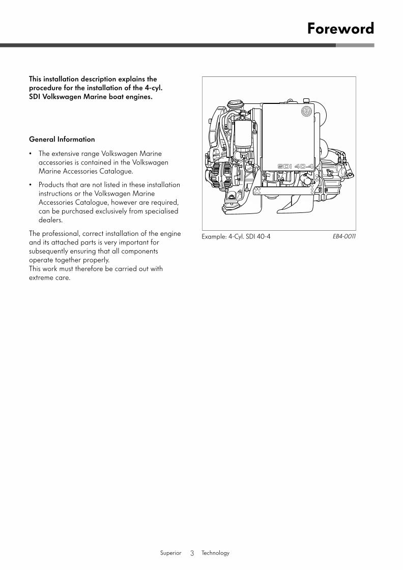
This installation description explains the procedure for the installation of the 4-cyl. SDI Volkswagen Marine boat engines.
General Information
• The extensive range Volkswagen Marine accessories is contained in the Volkswagen Marine Accessories Catalogue.
• Products that are not listed in these installation instructions or the Volkswagen Marine Accessories Catalogue, however are required, can be purchased exclusively from specialised dealers.
The professional, correct installation of the engine and its attached parts is very important for subsequently ensuring that all components operate together properly.This work must therefore be carried out with extreme care.
Foreword
EB4-0011
Example: 4-Cyl. SDI 40-4
4
Superior Technology
Foreword . . . . . . . . . . . . . . . . . . . . . . . . . . . . . . . . . . . . . 3
Installation Instructions. . . . . . . . . . . . . . . . . . . . . . . . . .6
Exhaust System . . . . . . . . . . . . . . . . . . . . . . . . . . . . . . . .8
Unit/Engine Mounting . . . . . . . . . . . . . . . . . . . . . . . . . 10
Electrical System . . . . . . . . . . . . . . . . . . . . . . . . . . . . . . 12
Connections on engine. . . . . . . . . . . . . . . . . . . . . . . . . . . . . . . . . . . . . 12
Instrumentation . . . . . . . . . . . . . . . . . . . . . . . . . . . . . . . . . . . . . . . . . . . 15
Installation overview of standard instrumentation . . . . . . . . . . . . . 16
Installation overview of instrumentation with dual engines . . . . . 20
Installation overview of instrument panels with second control stand . . . . . . . . . . . . . . . . . . . . . . . . . . . . . . . . . 22
Connecting first control stand (main instrumentation) . . . . . . . . . . . . . . . . . . . . . . . . . . . . . . . . . . . . 23
Connecting navigation instruments . . . . . . . . . . . . . . . . . . . . . . . . . 27
Connecting second control stand (flybridge instrumentation). . . . . . . . . . . . . . . . . . . . . . . . . . . . . . . . . 27
Engine Installation Dimensions . . . . . . . . . . . . . . . . . . 31
Installation dimensions for SDI Volkswagen Marine boat engine . . . . . . . . . . . . . . . . . . . . . . . . . . . . . . . . . . . . . . . . . . . . . . 31
Table of Contents
5
Superior Technology
Installation Dimensions for Engine with Reversing Gear . . . . . . . . . . . . . . . . . . . . . . . . . . .32
Cooling System . . . . . . . . . . . . . . . . . . . . . . . . . . . . . . .34
Cooling circuit . . . . . . . . . . . . . . . . . . . . . . . . . . . . . . . . . . . . . . . . . . . . 34
Seawater circuit . . . . . . . . . . . . . . . . . . . . . . . . . . . . . . . . . . . . . . . . . . 35
Fuel System . . . . . . . . . . . . . . . . . . . . . . . . . . . . . . . . . . 37
Operating description of fuel system . . . . . . . . . . . . . . . . . . . . . . . . 37
Engine Compartment Ventilation. . . . . . . . . . . . . . . . .39
Component Overview . . . . . . . . . . . . . . . . . . . . . . . . .40
Technical Data . . . . . . . . . . . . . . . . . . . . . . . . . . . . . . . .42
Installation Template for Flybridge Instrument Panel . . . . . . . . . . . . . . . . . . . . . . . . . . . . . .44
Installation Template for Main Instrument Panel . . . .45
6
Superior Technology
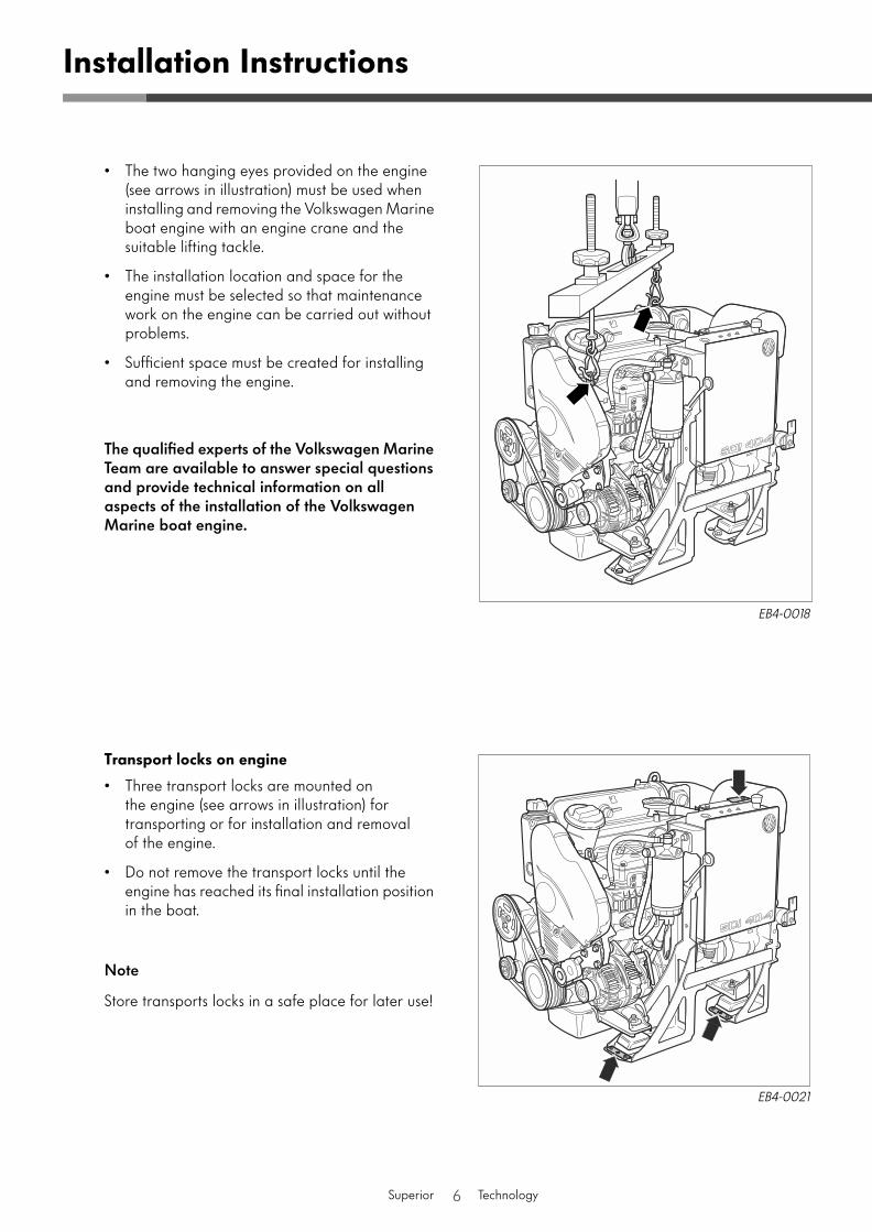
• The two hanging eyes provided on the engine (see arrows in illustration) must be used when installing and removing the Volkswagen Marine boat engine with an engine crane and the suitable lifting tackle.
• The installation location and space for the engine must be selected so that maintenance work on the engine can be carried out without problems.
• Sufficient space must be created for installing and removing the engine.
The qualified experts of the Volkswagen Marine Team are available to answer special questions and provide technical information on all aspects of the installation of the Volkswagen Marine boat engine.
Transport locks on engine
• Three transport locks are mounted on the engine (see arrows in illustration) for transporting or for installation and removal of the engine.
• Do not remove the transport locks until the engine has reached its final installation position in the boat.
Note
Store transports locks in a safe place for later use!
Installation Instructions
EB4-0018
EB4-0021
7
Superior Technology
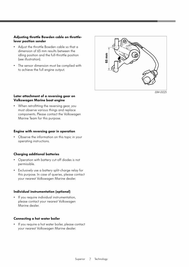
Adjusting throttle Bowden cable on throttle-lever position sender
• Adjust the throttle Bowden cable so that a dimension of 65 mm results between the idling position and the full-throttle position (see illustration).
• The sensor dimension must be complied with to achieve the full engine output.
Later attachment of a reversing gear on Volkswagen Marine boat engine
• When retrofitting the reversing gear, you must observe various things and replace components. Please contact the Volkswagen Marine Team for this purpose.
Engine with reversing gear in operation
• Observe the information on this topic in your operating instructions.
Charging additional batteries
• Operation with battery cut-off diodes is not permissible.
• Exclusively use a battery split-charge relay for this purpose. In case of queries, please contact your nearest Volkswagen Marine dealer.
Individual instrumentation (optional)
• If you require individual instrumentation, please contact your nearest Volkswagen Marine dealer.
Connecting a hot water boiler
• If you require a hot water boiler, please contact your nearest Volkswagen Marine dealer.
EB4-0025
8
Superior Technology
Exhaust System
EB4-0001
Introduction
Volkswagen Marine boat engines are operated with wet exhaust systems. The wet exhaust system has its name from the introduction of water.
After the exhaust plenum chamber or turbocharger the flow of exhaust gas is deflected through the exhaust-pipe connection piece. In these exhaust-pipe connection pieces the raw water/seawater is injected into the exhaust gas of the engine.
The raw water/seawater mixes with the exhaust gases and greatly cools them down so that rubber connection hoses and PVC parts can be used for the remainder of the exhaust system that must have a temperature stability of at least 200 °C.
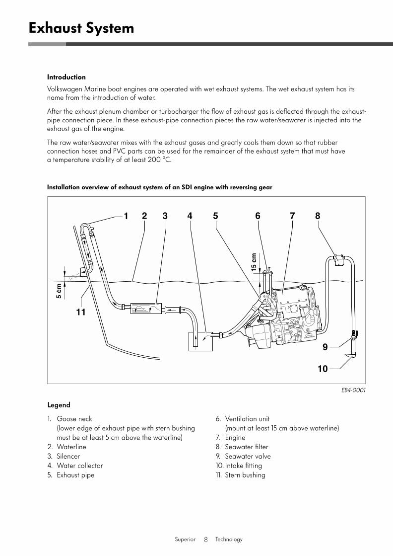
Installation overview of exhaust system of an SDI engine with reversing gear
Legend
1. Goose neck(lower edge of exhaust pipe with stern bushing must be at least 5 cm above the waterline)
2. Waterline3. Silencer4. Water collector5. Exhaust pipe
6. Ventilation unit (mount at least 15 cm above waterline)
7. Engine8. Seawater filter9. Seawater valve10. Intake fitting11. Stern bushing
9
Superior Technology
Legend
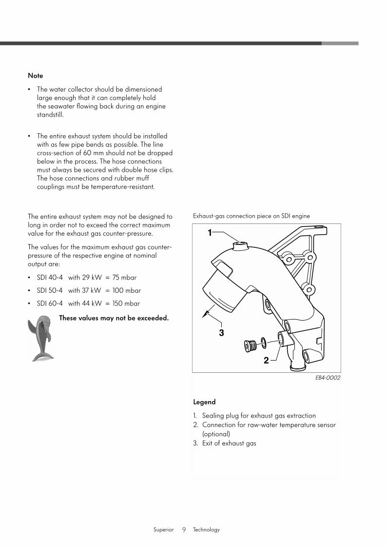
1. Sealing plug for exhaust gas extraction2. Connection for raw-water temperature sensor
(optional)3. Exit of exhaust gas
Note
• The water collector should be dimensioned large enough that it can completely hold the seawater flowing back during an engine standstill.
• The entire exhaust system should be installed with as few pipe bends as possible. The line cross-section of 60 mm should not be dropped below in the process. The hose connections must always be secured with double hose clips. The hose connections and rubber muff couplings must be temperature-resistant.
The entire exhaust system may not be designed to long in order not to exceed the correct maximum value for the exhaust gas counter-pressure.
The values for the maximum exhaust gas counter-pressure of the respective engine at nominal output are:
• SDI 40-4 with 29 kW = 75 mbar
• SDI 50-4 with 37 kW = 100 mbar
• SDI 60-4 with 44 kW = 150 mbar
These values may not be exceeded.
EB4-0002
Exhaust-gas connection piece on SDI engine
10
Superior Technology
Notes on installation of unit mountings
• The unit mountings may not be twisted during installation. Otherwise heavy vibrations and damage can occur.
• Make sure that there is no twisting on the output train and the unit mountings after installing and aligning the engine.
• Use only the original Volkswagen Marine unit mountings.
• The mounting bolts for the unit mountings on the boat hull must be provided with washers (see illustration on Page 11).
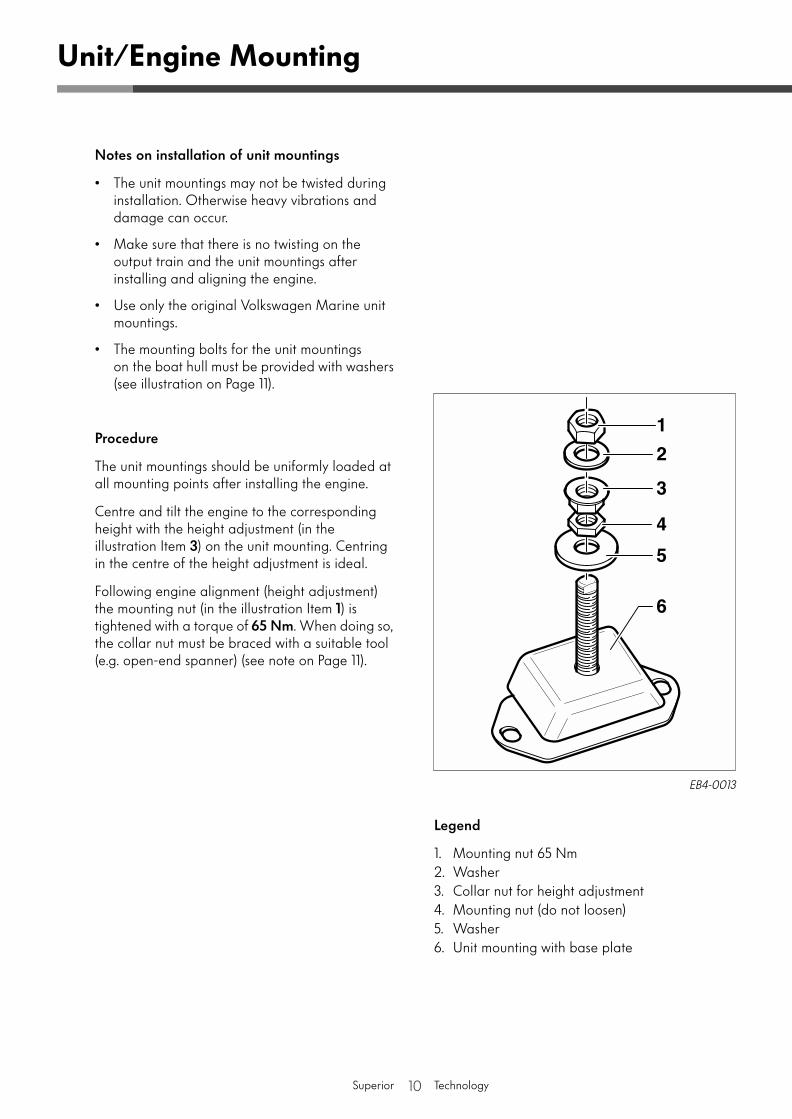
Procedure
The unit mountings should be uniformly loaded at all mounting points after installing the engine.
Centre and tilt the engine to the corresponding height with the height adjustment (in the illustration Item
3
) on the unit mounting. Centring in the centre of the height adjustment is ideal.
Following engine alignment (height adjustment) the mounting nut (in the illustration Item
1
) is tightened with a torque of
65 Nm
. When doing so, the collar nut must be braced with a suitable tool (e.g. open-end spanner) (see note on Page 11).
Legend
1. Mounting nut 65 Nm2. Washer3. Collar nut for height adjustment4. Mounting nut (do not loosen)5. Washer6. Unit mounting with base plate
Unit/Engine Mounting
EB4-0013
11
Superior Technology
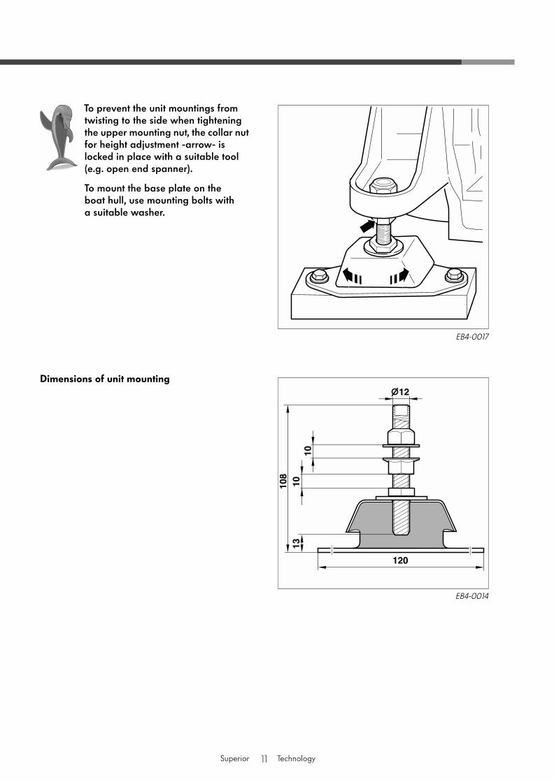
Dimensions of unit mounting
To prevent the unit mountings from twisting to the side when tightening the upper mounting nut, the collar nut for height adjustment -arrow- is locked in place with a suitable tool (e.g. open end spanner).
To mount the base plate on the boat hull, use mounting bolts with a suitable washer.
EB4-0017
EB4-0014
12
Superior Technology
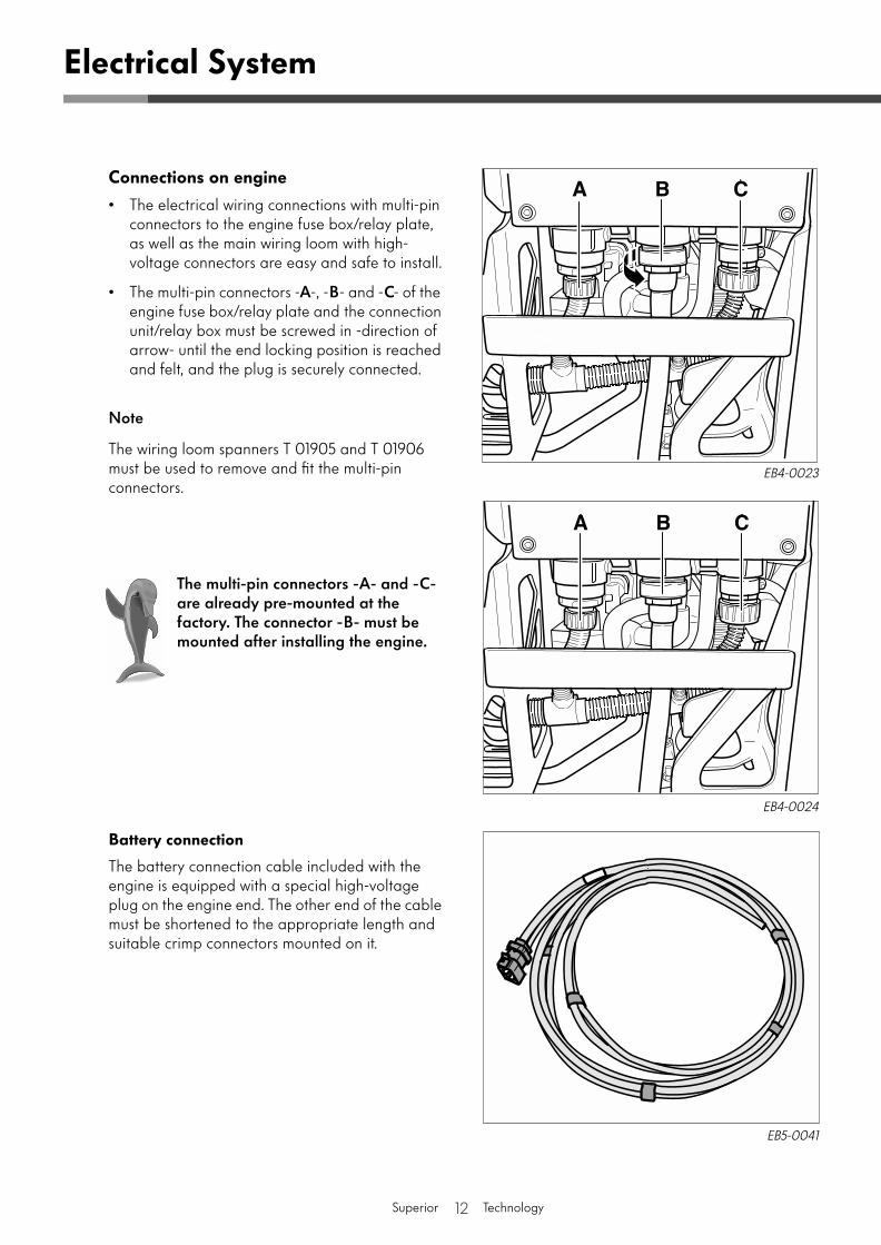
Connections on engine
• The electrical wiring connections with multi-pin connectors to the engine fuse box/relay plate, as well as the main wiring loom with high-voltage connectors are easy and safe to install.
• The multi-pin connectors -
A
-, -
B
- and -
C
- of the engine fuse box/relay plate and the connection unit/relay box must be screwed in -direction of arrow- until the end locking position is reached and felt, and the plug is securely connected.
Note
The wiring loom spanners T 01905 and T 01906 must be used to remove and fit the multi-pin connectors.
Battery connection
The battery connection cable included with the engine is equipped with a special high-voltage plug on the engine end. The other end of the cable must be shortened to the appropriate length and suitable crimp connectors mounted on it.
Electrical System
EB5-0041
EB4-0023
EB4-0024
The multi-pin connectors -A- and -C- are already pre-mounted at the factory. The connector -B- must be mounted after installing the engine.
13
Superior Technology
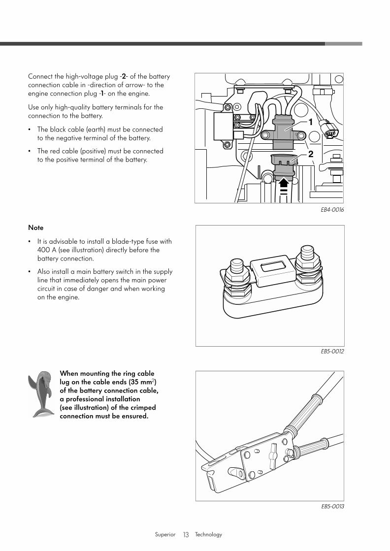
Connect the high-voltage plug -
2
- of the battery connection cable in -direction of arrow- to the engine connection plug -
1
- on the engine.
Use only high-quality battery terminals for the connection to the battery.
• The black cable (earth) must be connected to the negative terminal of the battery.
• The red cable (positive) must be connected to the positive terminal of the battery.
Note
• It is advisable to install a blade-type fuse with 400 A (see illustration) directly before the battery connection.
• Also install a main battery switch in the supply line that immediately opens the main power circuit in case of danger and when working on the engine.
When mounting the ring cable lug on the cable ends (35 mm
2
) of the battery connection cable, a professional installation (see illustration) of the crimped connection must be ensured.
EB4-0016
EB5-0012
EB5-0013
14
Superior Technology
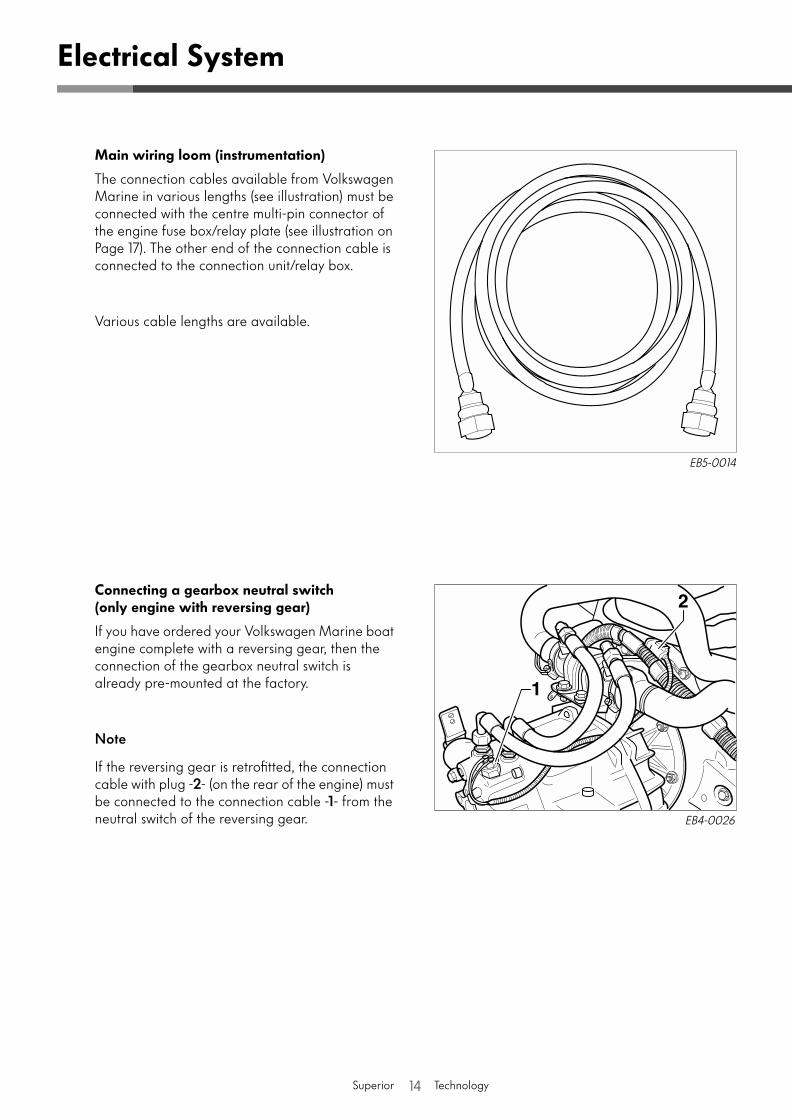
Main wiring loom (instrumentation)
The connection cables available from Volkswagen Marine in various lengths (see illustration) must be connected with the centre multi-pin connector of the engine fuse box/relay plate (see illustration on Page 17). The other end of the connection cable is connected to the connection unit/relay box.
Various cable lengths are available.
Connecting a gearbox neutral switch(only engine with reversing gear)
If you have ordered your Volkswagen Marine boat engine complete with a reversing gear, then the connection of the gearbox neutral switch is already pre-mounted at the factory.
Note
If the reversing gear is retrofitted, the connection cable with plug -
2
- (on the rear of the engine) must be connected to the connection cable -
1
- from the neutral switch of the reversing gear.
Electrical System
EB5-0014
EB4-0026
15
Superior Technology
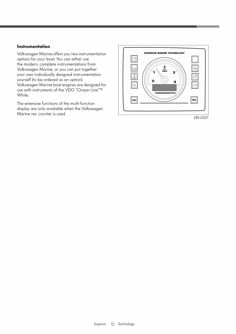
Instrumentation
Volkswagen Marine offers you two instrumentation options for your boat. You can either use the modern, complete instrumentations from Volkswagen Marine, or you can put together your own individually designed instrumentation yourself (to be ordered as an option).Volkswagen Marine boat engines are designed for use with instruments of the VDO "Ocean Line"™ White.
The extensive functions of the multi-function display are only available when the Volkswagen Marine rev. counter is used.
EB5-0037
16
Superior Technology
Electrical System
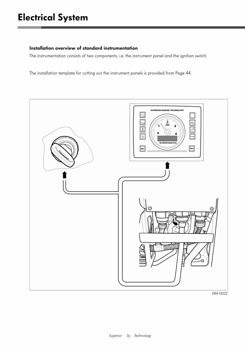
Installation overview of standard instrumentation
The instrumentation consists of two components, i.e. the instrument panel and the ignition switch.
The installation template for cutting out the instrument panels is provided from Page 44.
EB4-0022
17
Superior Technology
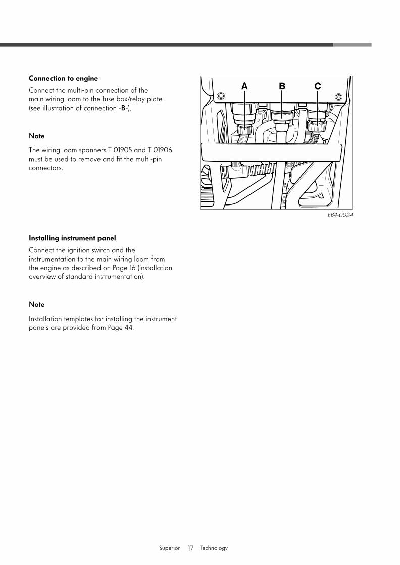
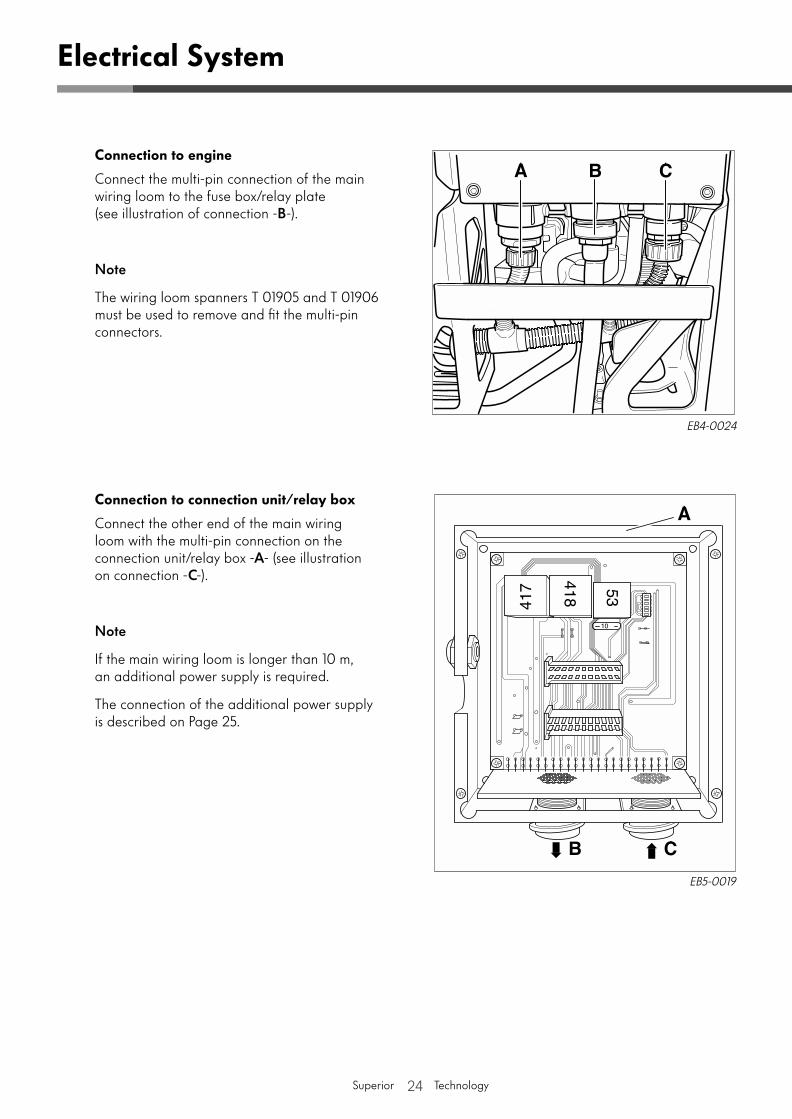
Connection to engine
Connect the multi-pin connection of the main wiring loom to the fuse box/relay plate (see illustration of connection -
B
-).
Note
The wiring loom spanners T 01905 and T 01906 must be used to remove and fit the multi-pin connectors.
Installing instrument panel
Connect the ignition switch and the instrumentation to the main wiring loom from the engine as described on Page 16 (installation overview of standard instrumentation).
Note
Installation templates for installing the instrument panels are provided from Page 44.
EB4-0024
18
Superior Technology
X3
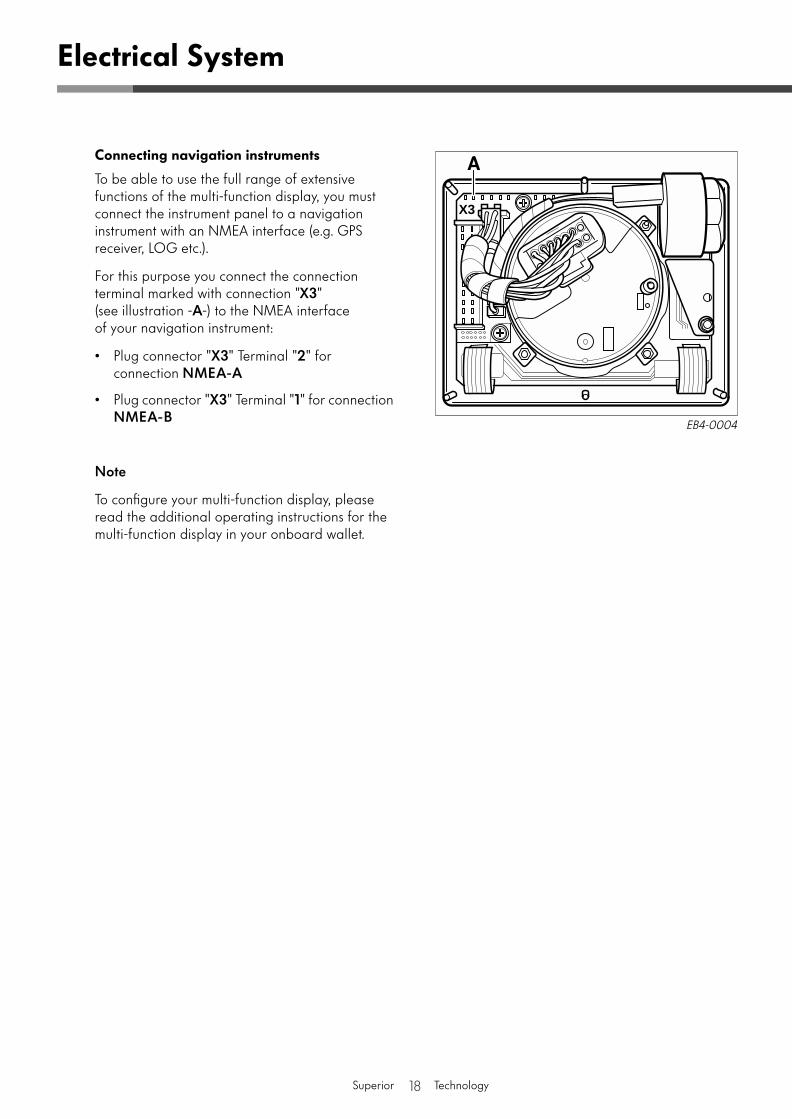
Connecting navigation instruments
To be able to use the full range of extensive functions of the multi-function display, you must connect the instrument panel to a navigation instrument with an NMEA interface (e.g. GPS receiver, LOG etc.).
For this purpose you connect the connection terminal marked with connection "
X3
" (see illustration -
A
-) to the NMEA interface of your navigation instrument:
• Plug connector "
X3
" Terminal "
2
" for connection
NMEA-A
• Plug connector "
X3
" Terminal "
1
" for connection
NMEA-B
Note
To configure your multi-function display, please read the additional operating instructions for the multi-function display in your onboard wallet.
Electrical System
EB4-0004

19
Superior Technology
20
Superior Technology
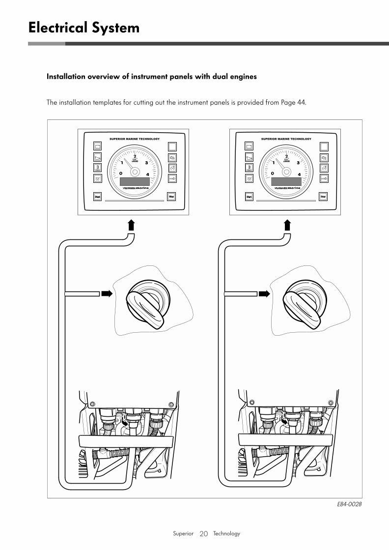
Installation overview of instrument panels with dual engines
The installation templates for cutting out the instrument panels is provided from Page 44.
EB4-0028
Electrical System
21
Superior Technology
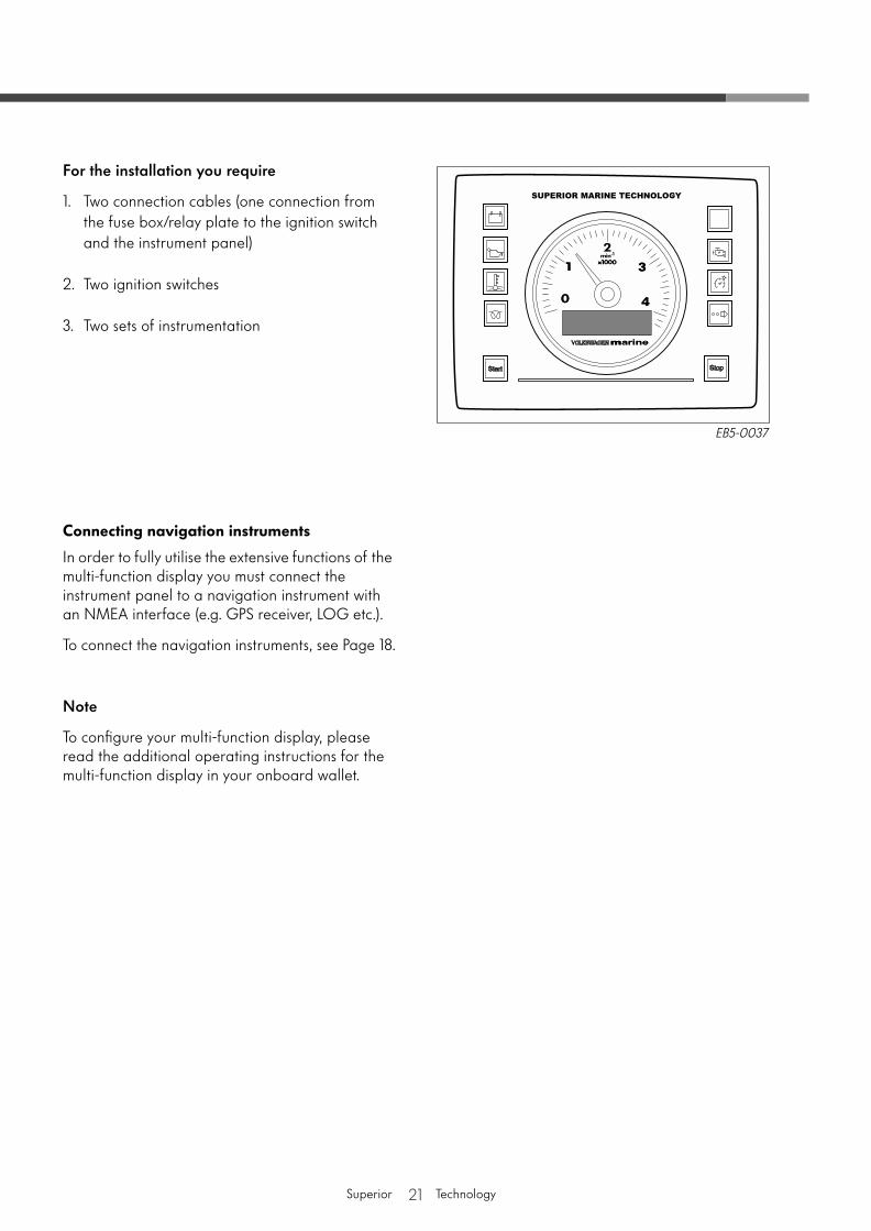
For the installation you require
1. Two connection cables (one connection from the fuse box/relay plate to the ignition switch and the instrument panel)
2. Two ignition switches
3. Two sets of instrumentation
Connecting navigation instruments
In order to fully utilise the extensive functions of the multi-function display you must connect the instrument panel to a navigation instrument with an NMEA interface (e.g. GPS receiver, LOG etc.).
To connect the navigation instruments, see Page 18.
Note
To configure your multi-function display, please read the additional operating instructions for the multi-function display in your onboard wallet.
EB5-0037
22
Superior Technology
Electrical System
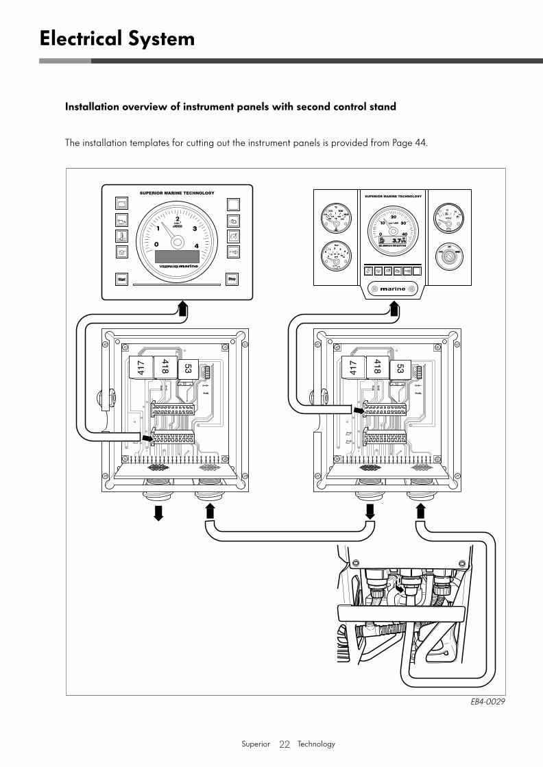
Installation overview of instrument panels with second control stand
The installation templates for cutting out the instrument panels is provided from Page 44.
EB4-0029
23
Superior Technology
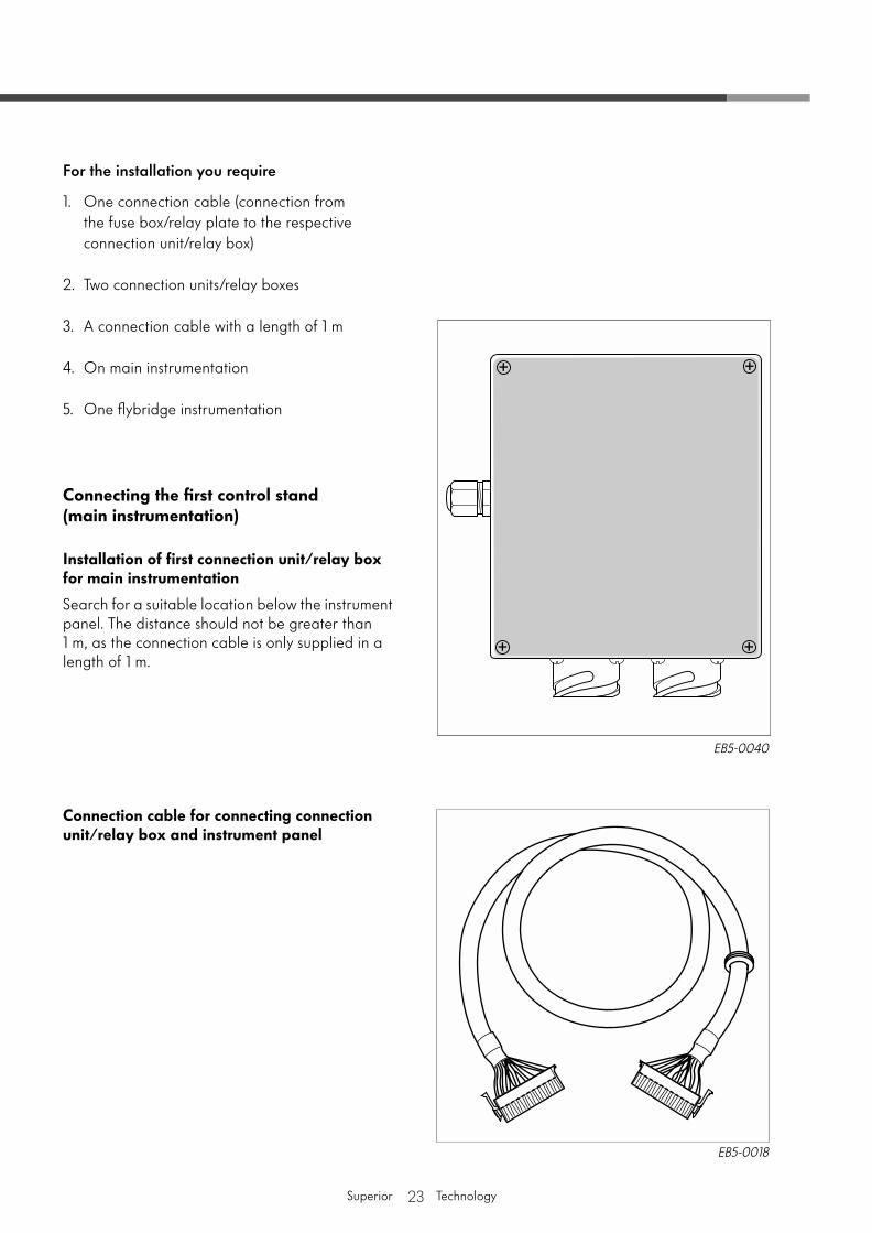
For the installation you require
1. One connection cable (connection from the fuse box/relay plate to the respective connection unit/relay box)
2. Two connection units/relay boxes
3. A connection cable with a length of 1 m
4. On main instrumentation
5. One flybridge instrumentation
Connecting the first control stand (main instrumentation)
Installation of first connection unit/relay box for main instrumentation
Search for a suitable location below the instrument panel. The distance should not be greater than 1 m, as the connection cable is only supplied in a length of 1 m.
Connection cable for connecting connection unit/relay box and instrument panel
EB5-0040
EB5-0018
24
Superior Technology
Connection to engine
Connect the multi-pin connection of the main wiring loom to the fuse box/relay plate (see illustration of connection -
B
-).
Note
The wiring loom spanners T 01905 and T 01906 must be used to remove and fit the multi-pin connectors.
Connection to connection unit/relay box
Connect the other end of the main wiring loom with the multi-pin connection on the connection unit/relay box -
A
- (see illustration on connection -
C
-).
Note
If the main wiring loom is longer than 10 m, an additional power supply is required.
The connection of the additional power supply is described on Page 25.
Electrical System
EB4-0024
EB5-0019
25
Superior Technology
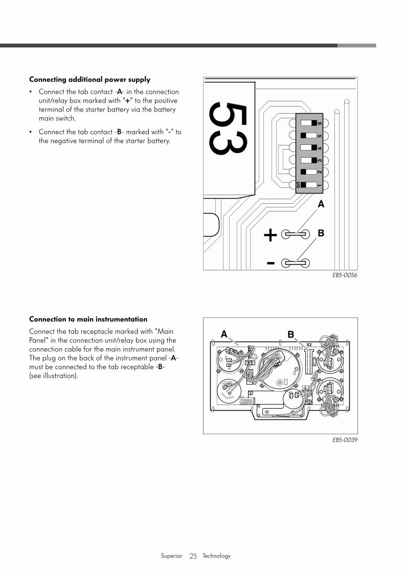
Connecting additional power supply
• Connect the tab contact -
A
- in the connection unit/relay box marked with "
+
" to the positive terminal of the starter battery via the battery main switch.
• Connect the tab contact -
B
- marked with "
-
" to the negative terminal of the starter battery.
Connection to main instrumentation
Connect the tab receptacle marked with "Main Panel" in the connection unit/relay box using the connection cable for the main instrument panel. The plug on the back of the instrument panel -
A
- must be connected to the tab receptable -
B
- (see illustration).
EB5-0056
EB5-0039
26
Superior Technology
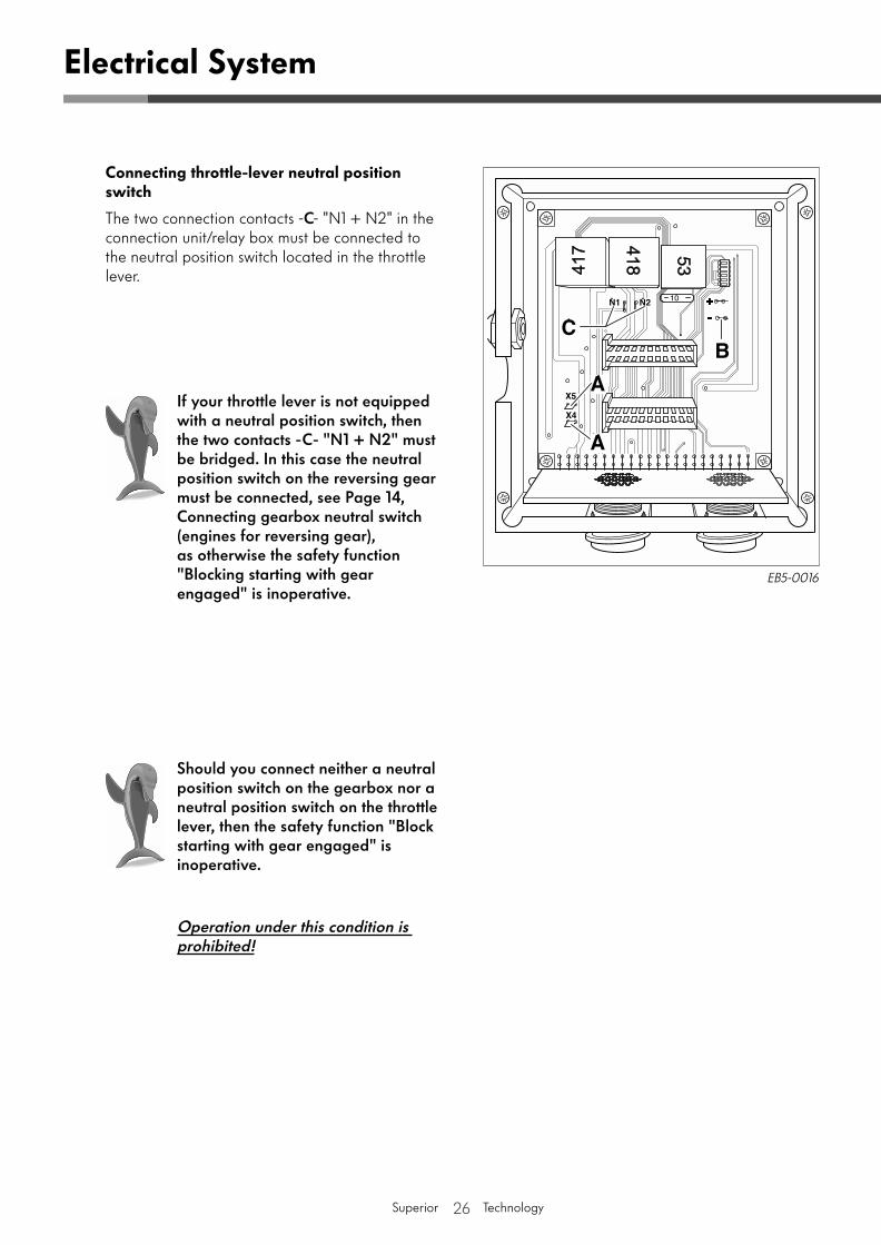
Connecting throttle-lever neutral position switch
The two connection contacts -
C
- "N1 + N2" in the connection unit/relay box must be connected to the neutral position switch located in the throttle lever.
Electrical System
EB5-0016
If your throttle lever is not equipped with a neutral position switch, then the two contacts -C- "N1 + N2" must be bridged. In this case the neutral position switch on the reversing gear must be connected, see Page 14, Connecting gearbox neutral switch (engines for reversing gear), as otherwise the safety function "Blocking starting with gear engaged" is inoperative.
Should you connect neither a neutral position switch on the gearbox nor a neutral position switch on the throttle lever, then the safety function "Block starting with gear engaged" is inoperative.
Operation under this condition is prohibited!
27
Superior Technology
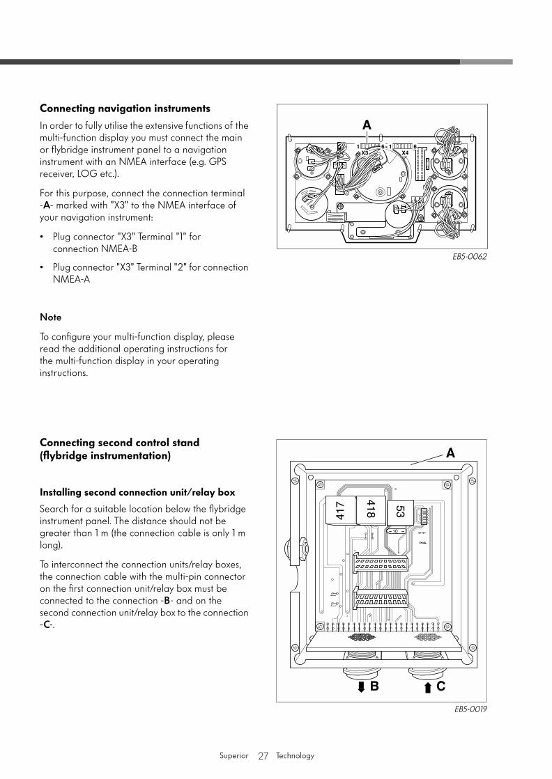
Connecting navigation instruments
In order to fully utilise the extensive functions of the multi-function display you must connect the main or flybridge instrument panel to a navigation instrument with an NMEA interface (e.g. GPS receiver, LOG etc.).
For this purpose, connect the connection terminal -
A
- marked with "X3" to the NMEA interface of your navigation instrument:
• Plug connector "X3" Terminal "1" for connection NMEA-B
• Plug connector "X3" Terminal "2" for connection NMEA-A
Note
To configure your multi-function display, please read the additional operating instructions for the multi-function display in your operating instructions.
Connecting second control stand (flybridge instrumentation)
Installing second connection unit/relay box
Search for a suitable location below the flybridge instrument panel. The distance should not be greater than 1 m (the connection cable is only 1 m long).
To interconnect the connection units/relay boxes, the connection cable with the multi-pin connector on the first connection unit/relay box must be connected to the connection -
B
- and on the second connection unit/relay box to the connection -
C
-.
EB5-0019
EB5-0062
28
Superior Technology
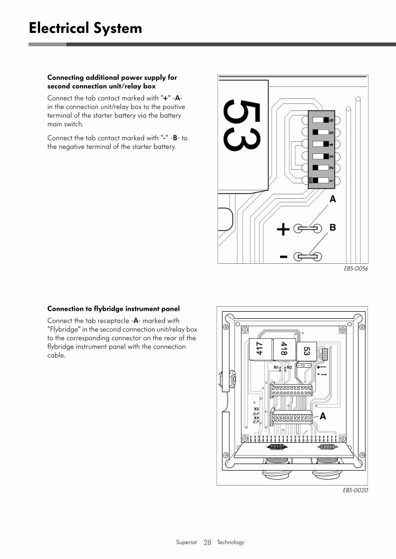
Connecting additional power supply for second connection unit/relay box
Connect the tab contact marked with "+" -A- in the connection unit/relay box to the positive terminal of the starter battery via the battery main switch.
Connect the tab contact marked with "-" -B- to the negative terminal of the starter battery.
Connection to flybridge instrument panel
Connect the tab receptacle -A- marked with "Flybridge" in the second connection unit/relay box to the corresponding connector on the rear of the flybridge instrument panel with the connection cable.
Electrical System
EB5-0056
EB5-0020
29Superior Technology
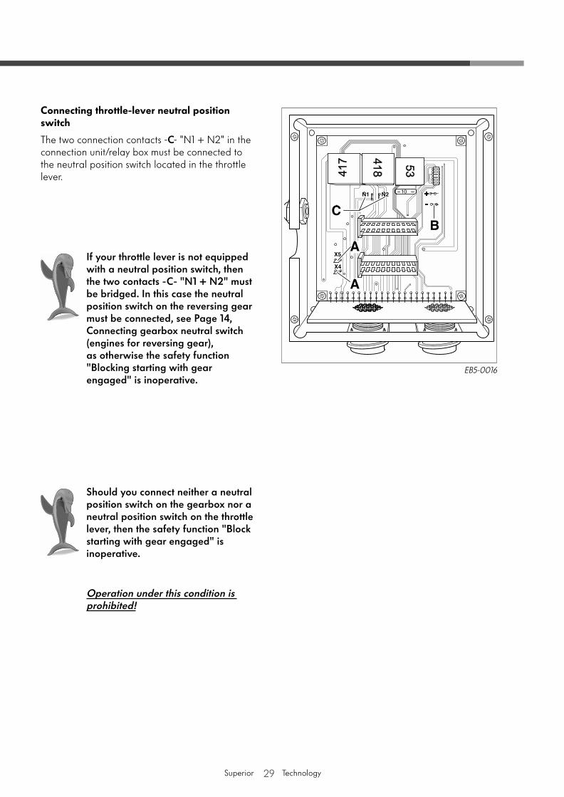
Connecting throttle-lever neutral position switch
The two connection contacts -C- "N1 + N2" in the connection unit/relay box must be connected to the neutral position switch located in the throttle lever.
EB5-0016
If your throttle lever is not equipped with a neutral position switch, then the two contacts -C- "N1 + N2" must be bridged. In this case the neutral position switch on the reversing gear must be connected, see Page 14, Connecting gearbox neutral switch (engines for reversing gear), as otherwise the safety function "Blocking starting with gear engaged" is inoperative.
Should you connect neither a neutral position switch on the gearbox nor a neutral position switch on the throttle lever, then the safety function "Block starting with gear engaged" is inoperative.
Operation under this condition is prohibited!
30Superior Technology
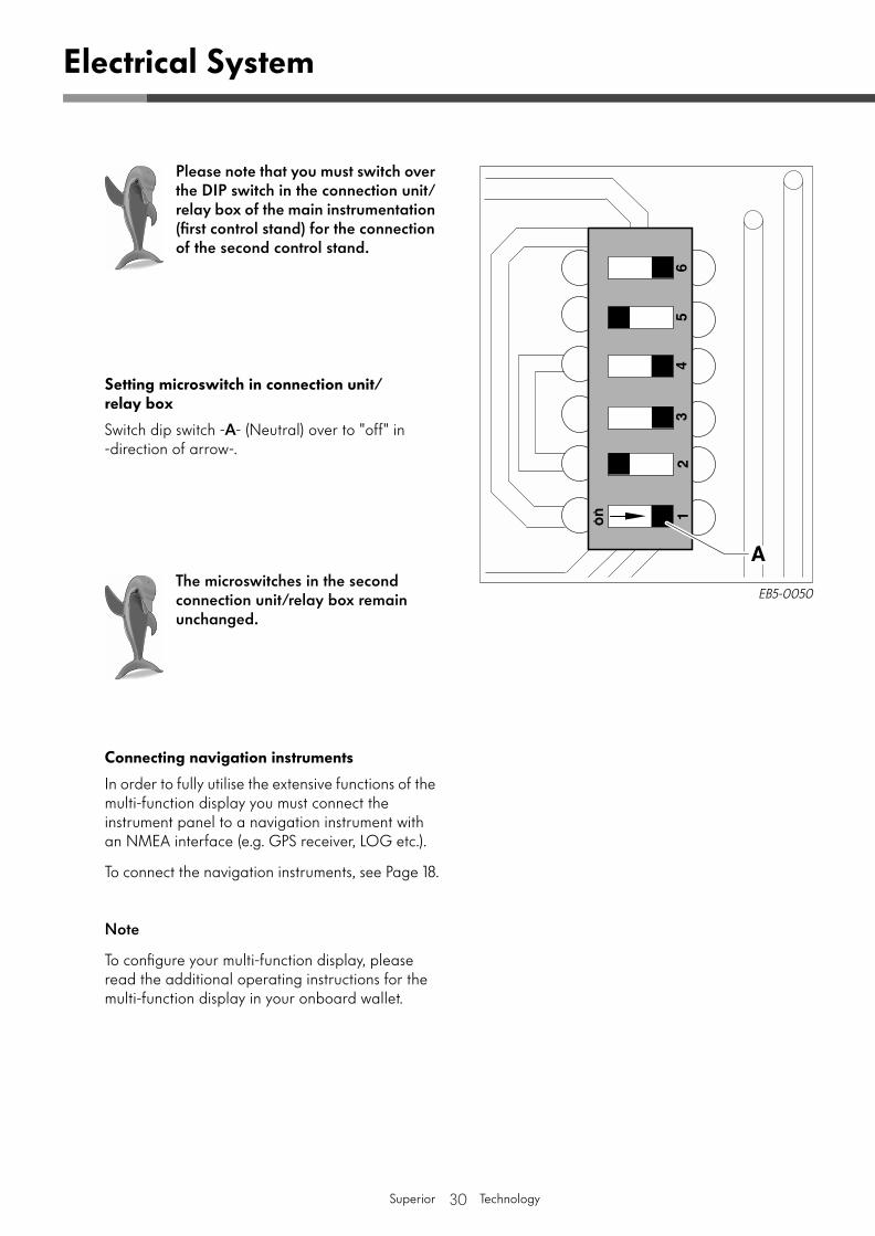
Setting microswitch in connection unit/relay box
Switch dip switch -A- (Neutral) over to "off" in -direction of arrow-.
Connecting navigation instruments
In order to fully utilise the extensive functions of the multi-function display you must connect the instrument panel to a navigation instrument with an NMEA interface (e.g. GPS receiver, LOG etc.).
To connect the navigation instruments, see Page 18.
Note
To configure your multi-function display, please read the additional operating instructions for the multi-function display in your onboard wallet.
Electrical System
EB5-0050
Please note that you must switch over the DIP switch in the connection unit/relay box of the main instrumentation (first control stand) for the connection of the second control stand.
The microswitches in the second connection unit/relay box remain unchanged.
31Superior Technology
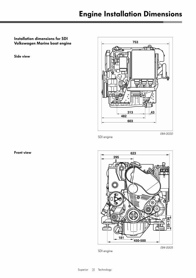
Installation dimensions for SDI Volkswagen Marine boat engine
Side view
Front view
Engine Installation Dimensions
EB4-0020SDI engine
EB4-0005SDI engine
32Superior Technology
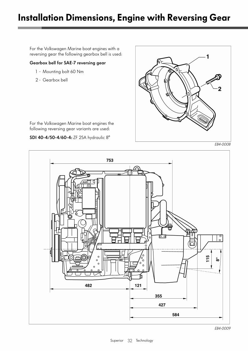
For the Volkswagen Marine boat engines with a reversing gear the following gearbox bell is used:
Gearbox bell for SAE-7 reversing gear
1 - Mounting bolt 60 Nm
2 - Gearbox bell
For the Volkswagen Marine boat engines the following reversing gear variants are used:
SDI 40-4/50-4/60-4: ZF 25A hydraulic 8°
Installation Dimensions, Engine with Reversing Gear
EB4-0009
EB4-0008
33Superior Technology
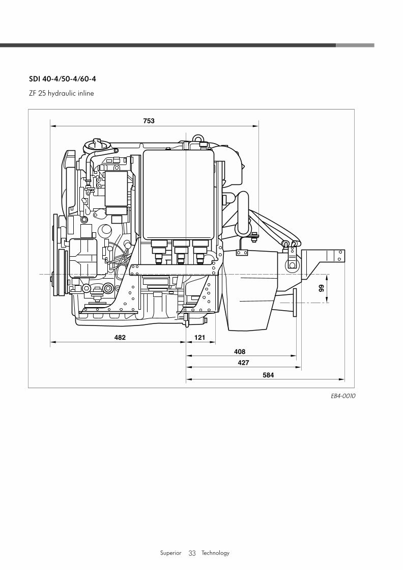
SDI 40-4/50-4/60-4
ZF 25 hydraulic inline
EB4-0010
34Superior Technology
Cooling System
Introduction
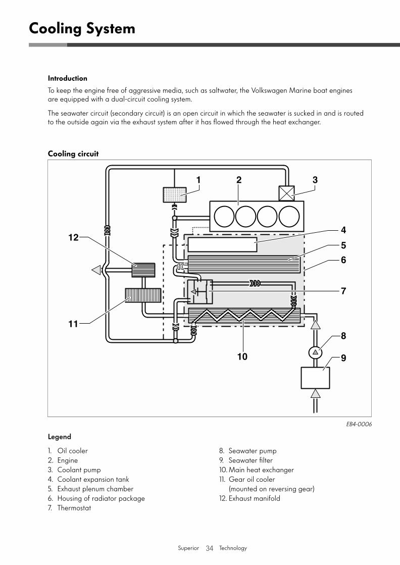
To keep the engine free of aggressive media, such as saltwater, the Volkswagen Marine boat engines are equipped with a dual-circuit cooling system.
The seawater circuit (secondary circuit) is an open circuit in which the seawater is sucked in and is routed to the outside again via the exhaust system after it has flowed through the heat exchanger.
Cooling circuit
EB4-0006
Legend
1. Oil cooler2. Engine3. Coolant pump4. Coolant expansion tank5. Exhaust plenum chamber6. Housing of radiator package7. Thermostat
8. Seawater pump9. Seawater filter10. Main heat exchanger11. Gear oil cooler
(mounted on reversing gear)12. Exhaust manifold
35Superior Technology
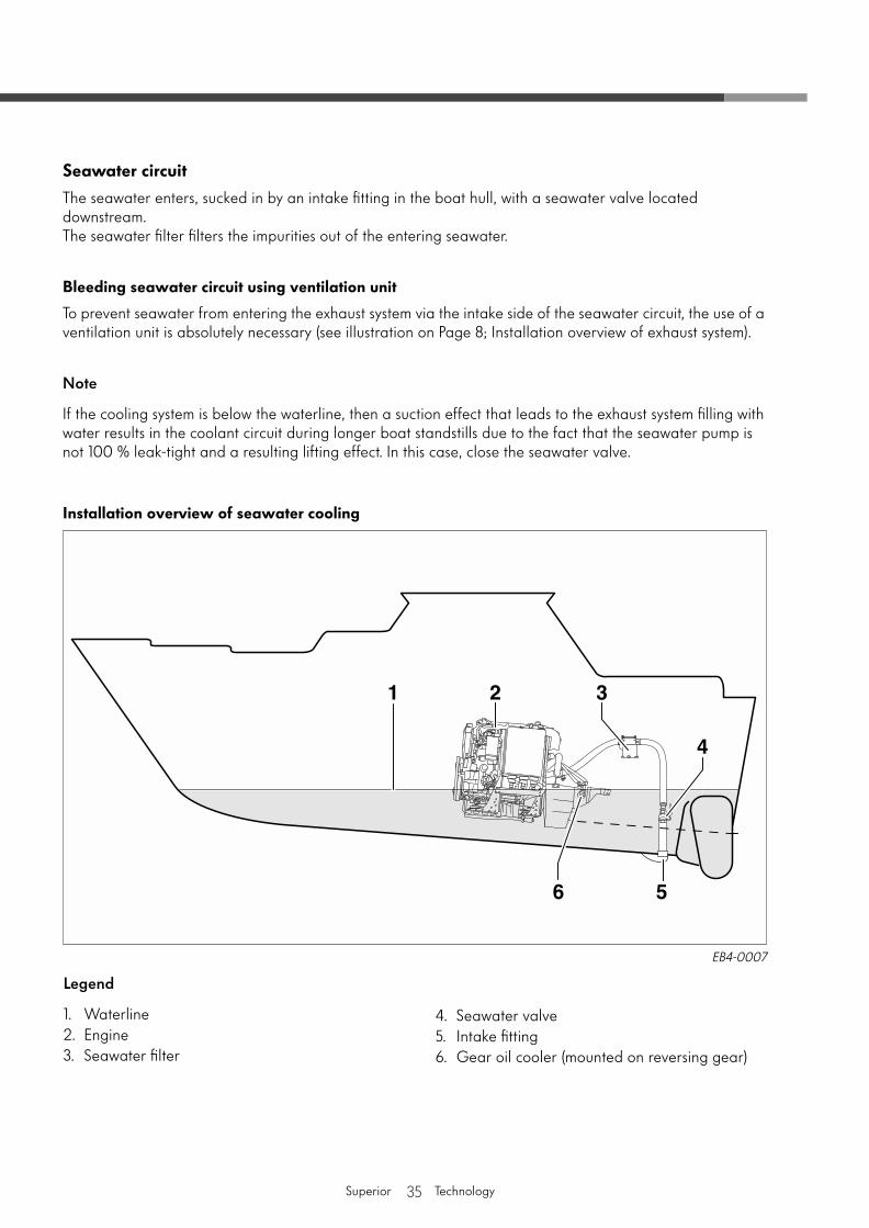
Seawater circuit
The seawater enters, sucked in by an intake fitting in the boat hull, with a seawater valve located downstream. The seawater filter filters the impurities out of the entering seawater.
Bleeding seawater circuit using ventilation unit
To prevent seawater from entering the exhaust system via the intake side of the seawater circuit, the use of a ventilation unit is absolutely necessary (see illustration on Page 8; Installation overview of exhaust system).
Note
If the cooling system is below the waterline, then a suction effect that leads to the exhaust system filling with water results in the coolant circuit during longer boat standstills due to the fact that the seawater pump is not 100 % leak-tight and a resulting lifting effect. In this case, close the seawater valve.
Installation overview of seawater cooling
EB4-0007
Legend
1. Waterline2. Engine3. Seawater filter
4. Seawater valve5. Intake fitting6. Gear oil cooler (mounted on reversing gear)
36Superior Technology
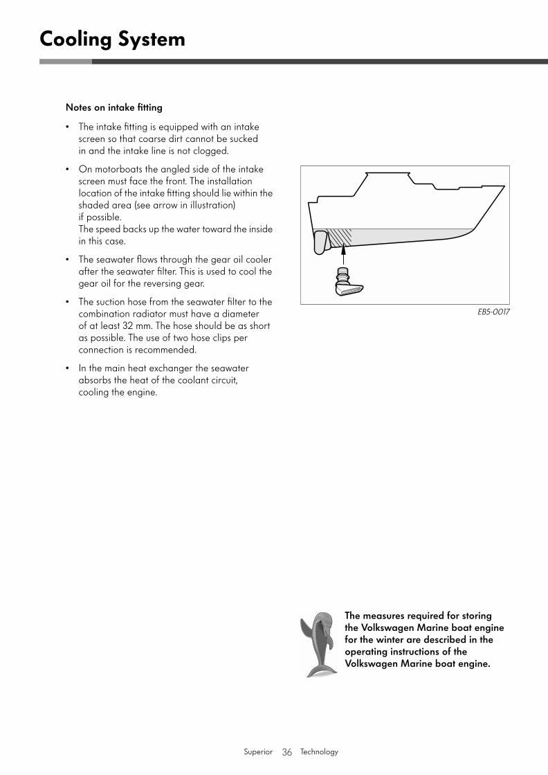
Notes on intake fitting
• The intake fitting is equipped with an intake screen so that coarse dirt cannot be sucked in and the intake line is not clogged.
• On motorboats the angled side of the intake screen must face the front. The installation location of the intake fitting should lie within the shaded area (see arrow in illustration) if possible. The speed backs up the water toward the inside in this case.
• The seawater flows through the gear oil cooler after the seawater filter. This is used to cool the gear oil for the reversing gear.
• The suction hose from the seawater filter to the combination radiator must have a diameter of at least 32 mm. The hose should be as short as possible. The use of two hose clips per connection is recommended.
• In the main heat exchanger the seawater absorbs the heat of the coolant circuit, cooling the engine.
Cooling System
The measures required for storing the Volkswagen Marine boat engine for the winter are described in the operating instructions of the Volkswagen Marine boat engine.
EB5-0017
37Superior Technology
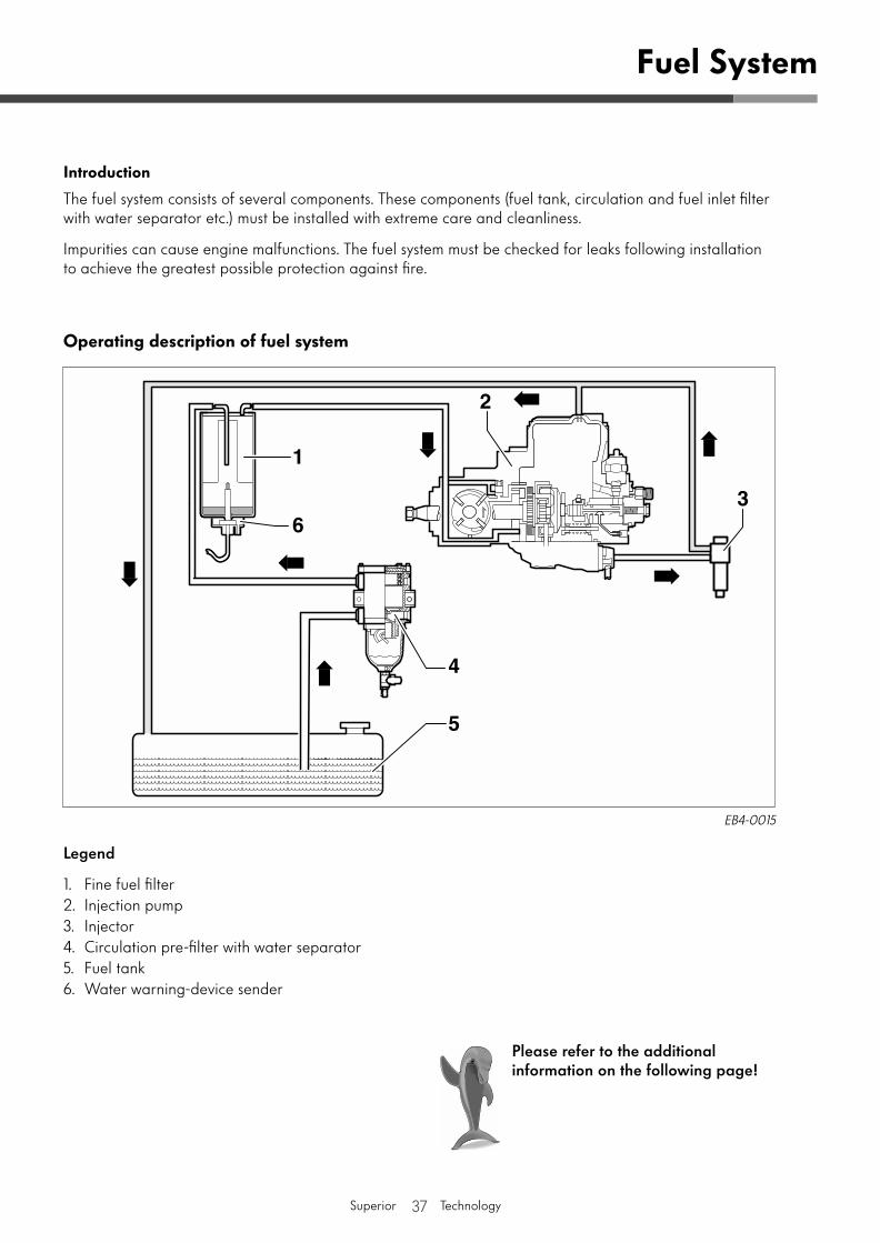
Legend
1. Fine fuel filter 2. Injection pump3. Injector4. Circulation pre-filter with water separator5. Fuel tank6. Water warning-device sender
Fuel System
EB4-0015
Please refer to the additional information on the following page!
Introduction
The fuel system consists of several components. These components (fuel tank, circulation and fuel inlet filter with water separator etc.) must be installed with extreme care and cleanliness.
Impurities can cause engine malfunctions. The fuel system must be checked for leaks following installation to achieve the greatest possible protection against fire.
Operating description of fuel system
38Superior Technology
Fuel System
• The space for the fuel system must be sufficiently ventilated. The fuel tanks and the filler necks must be provided with an earth connection to the battery (on steel boats to the boat hull).
• When arranging the components, ensure sufficient space for required maintenance work (and any necessary repair work).
• The fuel supply line must be routed from the fuel tank to the electrical fuel pump via the circulation pre-filter with a water separator via the fine fuel filter. The line cross-section must be at least 8 mm.
• A fuel return line must be routed from the combination radiator to the fuel tank. The line cross-section must be at least 8 mm.
• The return line from the injection pump to the gearbox radiator is already mounted at the factory.
• Fuel lines, seals and their connections must be suitable for RME fuel (rape-oil fatty acid methyl ester/bio diesel) (see Technical data on Page 40).
39Superior Technology
Engine Compartment Ventilation
• The engine must be supplied with air (oxygen) to ensure optimum fuel combustion.
• The engine compartment must be ventilated so that the engine compartment temperature can be maintained at the lowest possible optimum value (∆Tmax. to outside temperature: 10 °C to 5 °C).
• The air inlet must be mounted where the air sucked in is as pure as possible and the engines own exhaust gases cannot be sucked in to produce optimum engine compartment ventilation.
• Water may not flow into the air inlet and outlet.
• The hydraulic cross-section of the air inlet is to be 80 cm2.
• If other devices (e.g. an auxiliary heater) are located in the engine compartment which require oxygen for their operation, this must be taken into account during your planning of the air inlet.
Introduction
Diesel engines require a great deal of air. In the case of an insufficient air intake, increased black smoke can be recognised and the engine output decreases considerably.
40Superior Technology
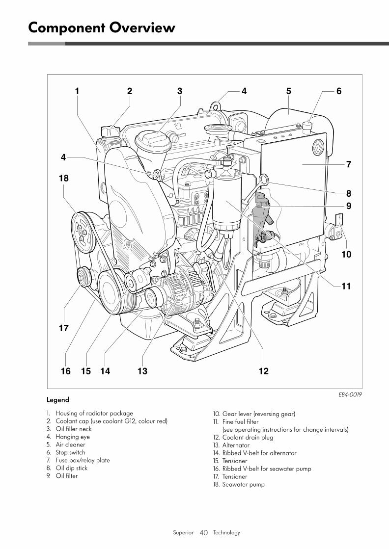
Component Overview
Legend
1. Housing of radiator package2. Coolant cap (use coolant G12, colour red)3. Oil filler neck 4. Hanging eye5. Air cleaner6. Stop switch7. Fuse box/relay plate8. Oil dip stick9. Oil filter
10. Gear lever (reversing gear)11. Fine fuel filter
(see operating instructions for change intervals)12. Coolant drain plug13. Alternator14. Ribbed V-belt for alternator15. Tensioner16. Ribbed V-belt for seawater pump17. Tensioner18. Seawater pump
EB4-0019
41Superior Technology
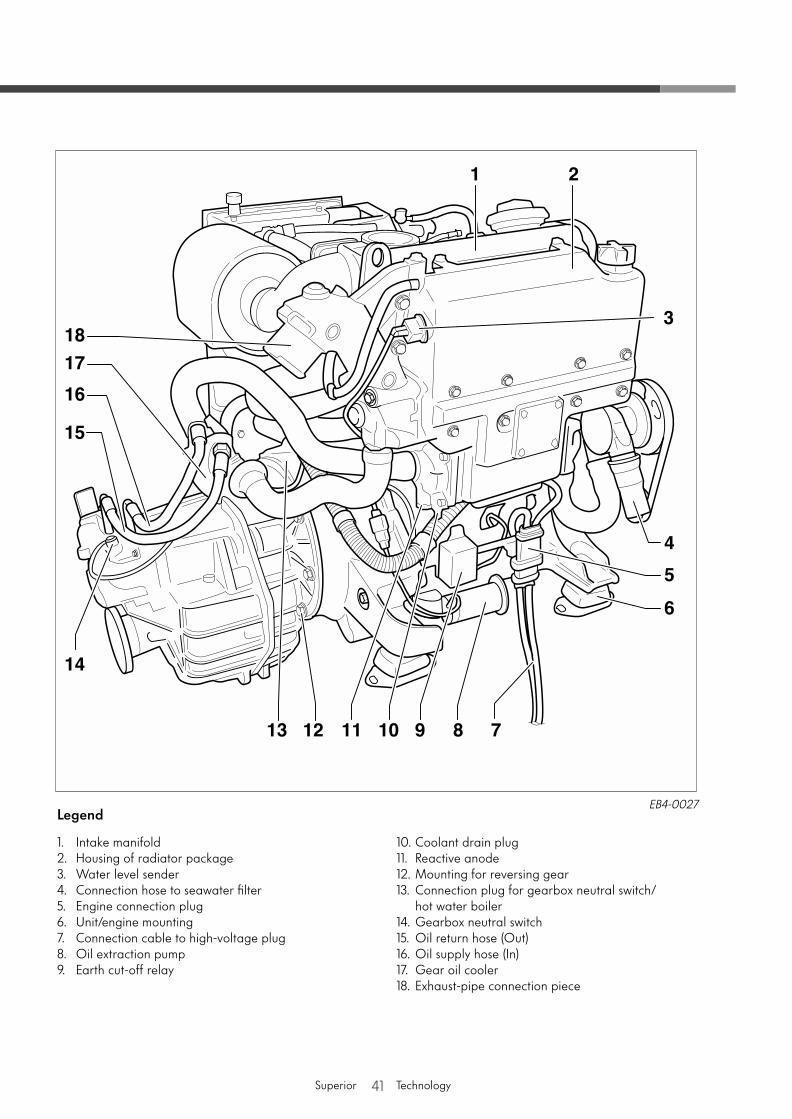
EB4-0027Legend
1. Intake manifold2. Housing of radiator package3. Water level sender4. Connection hose to seawater filter5. Engine connection plug6. Unit/engine mounting7. Connection cable to high-voltage plug8. Oil extraction pump9. Earth cut-off relay
10. Coolant drain plug11. Reactive anode12. Mounting for reversing gear13. Connection plug for gearbox neutral switch/
hot water boiler14. Gearbox neutral switch15. Oil return hose (Out)16. Oil supply hose (In)17. Gear oil cooler18. Exhaust-pipe connection piece

42Superior Technology
Engine description
Displacement cm3 1,896
Stroke/Bore mm 79.5/95.5
Compression ratio 19.5 : 1
Firing order 1-3-4-2
Output(as per ISO 3046 with marine control unit)
SDI 40-4 at 2600 rpm kW 29
SDI 50-4 at 3000 rpm kW 37
SDI 60-4 at 3600 rpm kW 44
Weight
SDI 40-4 kg approx. 198
SDI 50-4 kg approx. 198
SDI 60-4 kg approx. 198
Maximum operating inclination
15° in all directions
30° short-term
Permissible engine operating data
Permissible engine oil temperature
max. permissible temperature °C (°F) 130 (266)in oil sump
Permissible coolant temperature
max. permissible temperature °C (°F) 105 (221)on engine outlet during continuous operation
Electrical engine equipment
AC alternator, 12 V A 90
Starter 12 V kW 1.8
Battery 12 V A (Ah) 380 (63)Minimum capacity
Sheathed-element glow plugs V 12
Control unit
Manufacturer Bosch EDC 15 V +
Fault memory present:
Checking with fault reader V.A.G 1552/1551 or the vehicle diagnosis, measuring and information system VAS 5052/5051.
Technical Data
<)°
43Superior Technology
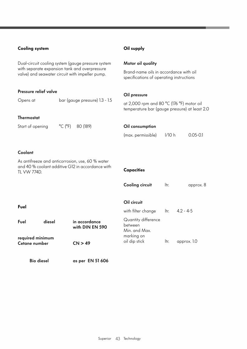
Cooling system
Dual-circuit cooling system (gauge pressure system with separate expansion tank and overpressure valve) and seawater circuit with impeller pump.
Pressure relief valve
Opens at bar (gauge pressure) 1.3 - 1.5
Thermostat
Start of opening °C (°F) 80 (189)
Coolant
As antifreeze and anticorrosion, use, 60 % water and 40 % coolant additive G12 in accordance with TL VW 774D.
Fuel
Fuel diesel in accordance with DIN EN 590
required minimum Cetane number CN > 49
Bio diesel as per EN 51 606
Oil supply
Motor oil quality
Brand-name oils in accordance with oil specifications of operating instructions
Oil pressure
at 2,000 rpm and 80 °C (176 °F) motor oil temperature bar (gauge pressure) at least 2.0
Oil consumption
(max. permissible) l/10 h 0.05-0.1
Capacities
Cooling circuit ltr. approx. 8
Oil circuit
with filter change ltr. 4.2 - 4-5
Quantity difference between Min. and Max. marking on oil dip stick ltr. approx. 1.0
44Superior Technology
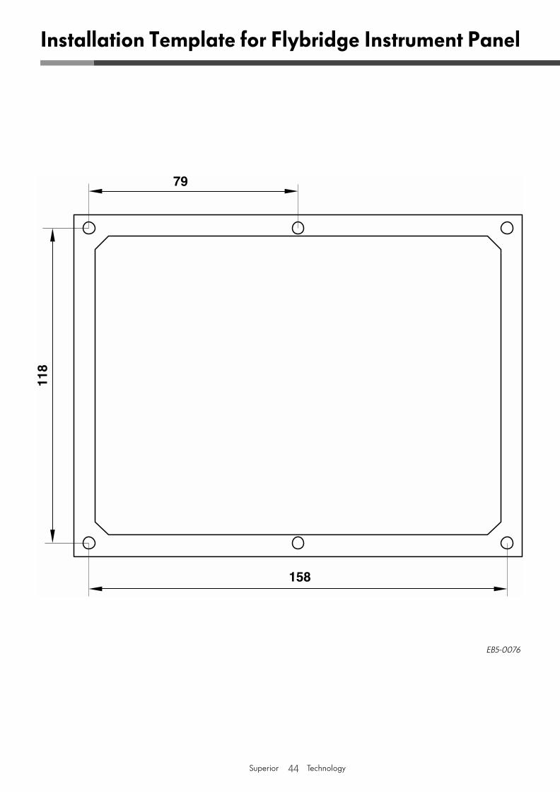
Installation Template for Flybridge Instrument Panel
EB5-0076
45Superior Technology
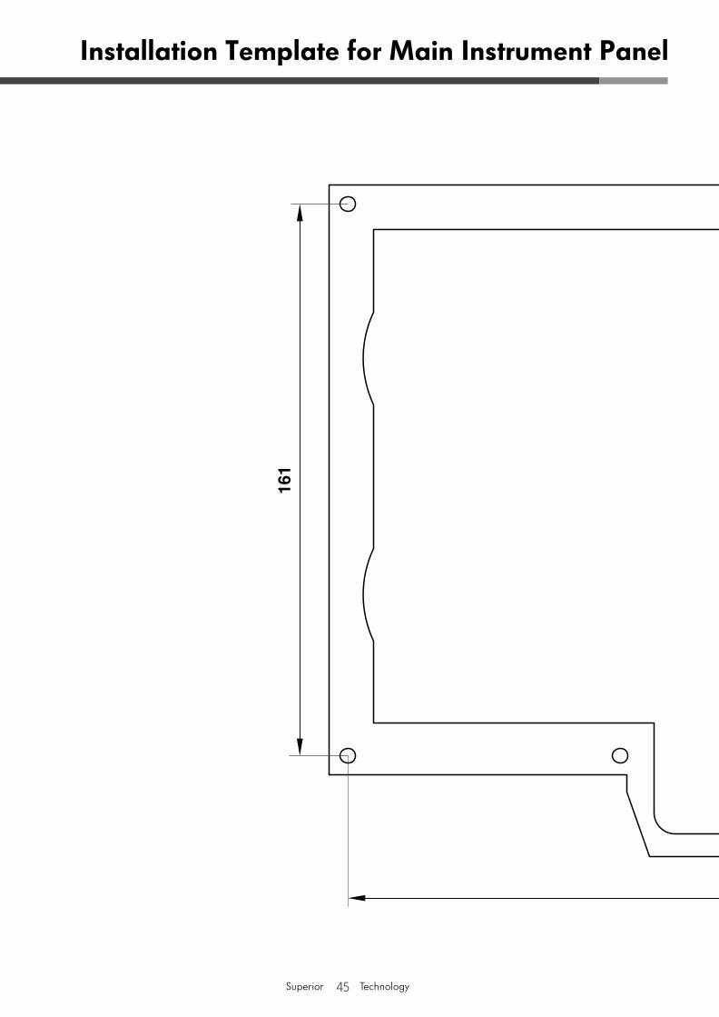
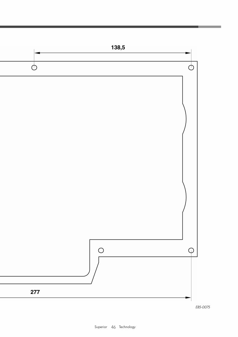
Installation Template for Main Instrument Panel
46Superior Technology
EB5-0075

47Superior Technology
Installation Template for Main Instrument Panel
- PLEASE FOLD OPEN HERE! -

48Superior Technology

49Superior Technology
Installation Description EB02
© 2003 Volkswagen Marine
The texts, illustrations and standards in this Owner's Manual are based on the information available at the time of going to print. Reproduction, duplication and translation, in whole or part, only with the express written permission of Volkswagen Marine. All copyrights and patent rights are expressly reserved by Volkswagen Marine. We reserve the right to introduce editorial revisions at any time.Editorial Deadline 04/03
Postfach 31 11 76, 38231 SalzgitterEdition 04/03 Publication Number 064.991.EB4.20
❀ This paper was manufactured from pulp bleached without using chlorine.


![[VOLKSWAGEN] Manual Despiece Volkswagen Gol Trend G5](https://static.fdocuments.us/doc/165x107/577c83781a28abe054b511d0/volkswagen-manual-despiece-volkswagen-gol-trend-g5.jpg)